US7590219B2 - Automatically determining a beam parameter for radiation treatment planning - Google Patents
Automatically determining a beam parameter for radiation treatment planningDownload PDFInfo
- Publication number
- US7590219B2 US7590219B2US11/731,115US73111507AUS7590219B2US 7590219 B2US7590219 B2US 7590219B2US 73111507 AUS73111507 AUS 73111507AUS 7590219 B2US7590219 B2US 7590219B2
- Authority
- US
- United States
- Prior art keywords
- treatment
- radiation
- target
- dose
- parameter
- Prior art date
- Legal status (The legal status is an assumption and is not a legal conclusion. Google has not performed a legal analysis and makes no representation as to the accuracy of the status listed.)
- Active, expires
Links
Images


Classifications
- A—HUMAN NECESSITIES
- A61—MEDICAL OR VETERINARY SCIENCE; HYGIENE
- A61N—ELECTROTHERAPY; MAGNETOTHERAPY; RADIATION THERAPY; ULTRASOUND THERAPY
- A61N5/00—Radiation therapy
- A61N5/10—X-ray therapy; Gamma-ray therapy; Particle-irradiation therapy
- A61N5/103—Treatment planning systems
- A—HUMAN NECESSITIES
- A61—MEDICAL OR VETERINARY SCIENCE; HYGIENE
- A61N—ELECTROTHERAPY; MAGNETOTHERAPY; RADIATION THERAPY; ULTRASOUND THERAPY
- A61N5/00—Radiation therapy
- A61N5/10—X-ray therapy; Gamma-ray therapy; Particle-irradiation therapy
- A61N5/1042—X-ray therapy; Gamma-ray therapy; Particle-irradiation therapy with spatial modulation of the radiation beam within the treatment head
- G—PHYSICS
- G21—NUCLEAR PHYSICS; NUCLEAR ENGINEERING
- G21K—TECHNIQUES FOR HANDLING PARTICLES OR IONISING RADIATION NOT OTHERWISE PROVIDED FOR; IRRADIATION DEVICES; GAMMA RAY OR X-RAY MICROSCOPES
- G21K1/00—Arrangements for handling particles or ionising radiation, e.g. focusing or moderating
- G21K1/02—Arrangements for handling particles or ionising radiation, e.g. focusing or moderating using diaphragms, collimators
- G21K1/04—Arrangements for handling particles or ionising radiation, e.g. focusing or moderating using diaphragms, collimators using variable diaphragms, shutters, choppers
- G21K1/046—Arrangements for handling particles or ionising radiation, e.g. focusing or moderating using diaphragms, collimators using variable diaphragms, shutters, choppers varying the contour of the field, e.g. multileaf collimators
- A—HUMAN NECESSITIES
- A61—MEDICAL OR VETERINARY SCIENCE; HYGIENE
- A61N—ELECTROTHERAPY; MAGNETOTHERAPY; RADIATION THERAPY; ULTRASOUND THERAPY
- A61N5/00—Radiation therapy
- A61N5/10—X-ray therapy; Gamma-ray therapy; Particle-irradiation therapy
- A61N5/103—Treatment planning systems
- A61N5/1036—Leaf sequencing algorithms
Definitions
- Embodiments of the present inventionrelate generally to radiation treatment and, more particularly, to treatment planning in radiation treatment.
- Tumors and lesionsare types of pathological anatomies characterized by abnormal growth of tissue resulting from the uncontrolled, progressive multiplication of cells, while serving no physiological function. Pathological anatomies can be treated with an invasive procedure, such as surgery, but this can be harmful and full of risks for the patient.
- a non-invasive method to treat a pathological anatomye.g., tumor, legion, vascular malformation, nerve disorder, etc.
- an external radiation sourceis used to direct a sequence of x-ray beams at a tumor site from multiple angles, with the patient positioned so the tumor lies in the path of the beam. As the angle of the radiation source changes, every beam passes through the tumor site, but passes through a different area of healthy tissue on its way to the tumor. As a result, the cumulative radiation dose at the tumor is high and the average radiation dose to healthy tissue is low.
- radiotherapyrefers to a radiation treatment procedure in which radiation is applied to a target region for therapeutic, rather than necrotic, purposes.
- the amount of radiation utilized in radiotherapy treatment sessionsis typically about an order of magnitude smaller, as compared to the amount used in a radiosurgery session.
- Radiotherapyis typically characterized by a low dose per treatment (e.g., 100-200 centigray (cGy)), short treatment times (e.g., 10 to 30 minutes per treatment) and conventional or hyperfractionation (e.g., 30 to 45 days of treatment).
- dose per treatmente.g., 100-200 centigray (cGy)
- short treatment timese.g., 10 to 30 minutes per treatment
- conventional or hyperfractionatione.g., 30 to 45 days of treatment.
- the term “radiation treatment”is used herein to mean radiosurgery and/or radiotherapy unless otherwise noted by the magnitude of the radiation.
- Treatment plansspecify quantities such as the directions and intensities of the applied radiation beams, and the durations of the beam exposure. It is desirable that treatment plans be designed in such a way that a specified dose (required for the clinical purpose at hand) be delivered to a tumor, while avoiding an excessive dose to the surrounding healthy tissue and, in particular, to any important nearby organs. Developing an appropriate treatment planning system is especially challenging for tumors that are larger, have irregular shapes, or are close to a sensitive or critical structure.
- a treatment planmay typically be generated from input parameters such as beam positions, beam orientations, beam shapes, beam intensities, and desired radiation dose constraints (that are deemed necessary by the radiologist in order to achieve a particular clinical goal).
- Sophisticated treatment plansmay be developed using advanced modeling techniques, and state-of-the-art optimization algorithms.
- forward planningTwo kinds of treatment planning procedures are known: forward planning and inverse planning.
- treatment planning systemstended to focus on forward planning techniques.
- forward treatment planninga medical physicist determines the radiation dose duration, or beam-on time, and trajectory of a chosen beam and then calculates how much radiation will be absorbed by the tumor, critical structures (i.e., vital organs) and other healthy tissue.
- critical structuresi.e., vital organs
- the medical physicistmay “guess” or assign, based on his experience, values to various treatment parameters such as beam positions and beam intensities.
- the treatment planning systemthen calculates the resulting dose distribution.
- the medical physicistmay adjust the values of the treatment parameters.
- the systemre-calculates a new resulting dose distribution. This process may be repeated, until the medical physicist is satisfied by the resulting dose distribution, as compared to his desired distribution.
- Forward planningtends to rely on the user's ability to iterate through various selections of beam directions and dose weights, and to properly evaluate the resulting dose distributions. The more experienced the user, the more likely that a satisfactory dose distribution will be produced.
- Forward planningoften utilizes an isocentric treatment process in which an external radiation source is used to direct a sequence of x-ray beams at a tumor target from multiple angles, with the patient being positioned so the tumor is at the center of rotation (isocenter) of the beams.
- each available beamis targeted at the same point to form the “isocenter,” which generally may be a roughly spherical isodose region as represented by a sphere.
- isocentric planningmay be often applied when treating a tumor that has a substantially regular (e.g., spherical) shape.
- the radiation beamsare shaped by a device called a collimator.
- the collimatorconsists of dense material that is opaque to radiation, with the exception that there is a hollow portion through which radiation may pass.
- the shape and size of the radiation beamis then determined by the shape and size of this hollow portion (aperture).
- collimator sizewe mean the size of radiation beam created by a given collimator configuration, as measured at a given distance from the radiation source.
- the size of the sphere of radiation dose in isocentric planningmay depend on the collimator size which may be, for example, about 30 millimeters as measured at about 800 millimeters from the radiation source. As the angle of the radiation source is changed, every beam passes through the tumor, but may pass through a different area of healthy tissue on its way to the tumor.
- multiple dose spheresare superimposed or “stacked” on each other in an attempt to obtain a contour that closely matches the silhouette of the pathological anatomy.
- a planmay be developed that ensures that nearly all the target receives a sufficient dose.
- the cumulative radiation dose at the tumormay be high and the average radiation dose to healthy tissue may be low.
- the radiation beammay be shaped by a multileaf collimator (MLC), to conform to the silhouette of the target as seen from the orientation of the radiation beam source.
- MLCmultileaf collimator
- the MLCis mounted on a gantry and coupled to a linear accelerator.
- the MLCincludes several adjustable leaves which are able to block and/or filter radiation to vary the beam intensity and control distribution of the radiation.
- the leavesare typically made of a dense material (e.g., tungsten) that is essentially opaque to radiation, and are mechanically driven, individually, in and out of the radiation field of the beam to create a radiation field shape.
- FIG. 1shows the leaves of an MLC adjusted to create a radiation field shape corresponding to a target silhouette.
- IMRTIntensity Modulated Radiation Therapy
- treatment planningis performed by, first, determining an optimal dose distribution at each node of the treatment system, i.e. each desired angle.
- field shapesare generated using a leaf sequencing algorithm, taking into account constraints of the MLC. That is, a set of instructions is generated to move the leaves in a given pattern, in order to achieve as closely as possible the optimum dose distribution.
- the radiation treatment of the target volume of interest (“VOI”)occurs.
- treatment planningis performed by first matching the leaves of the MLC to the target silhouette.
- the planning componentseeks only to match the shape of each beam to the silhouette of the target from that gantry angle.
- a predicted dose distributionmay be generated, and the radiation treatment of the target VOI occurs.
- Another mode of delivering radiation treatmentis that provided by the CyberKnife® system. Instead of moving the radiation delivery device in a circle around the patient, it is mounted on a multi-jointed robotic manipulator that has freedom to make both translational and rotational movement. Hence, radiation may be delivered from a wide range of positions and orientations relative to the patient, instead of being restricted to angles chosen within the circular arc on which the gantry-mounted linac can travel.
- FIG. 1is a plan view of a multileaf collimator adjusted to conform to a pathological anatomy
- FIG. 2is a schematic of a graphical output of a treatment planning software displaying a slice of a CT image
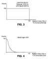
- FIG. 3is a graph showing an ideal DVH for a pathological anatomy
- FIG. 4is a graph showing a desirable DVH for a critical region
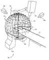
- FIG. 5is a perspective view of a radiation treatment system having spatial nodes in accordance with one embodiment of the invention.
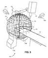
- FIG. 6is a perspective view of a collimator at different orientations in accordance with one embodiment of the invention.
- FIG. 7Ais a flow chart of one implementation of a treatment planning algorithm
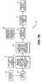
- FIG. 7Bis a flow chart of one implementation of a treatment planning algorithm in accordance with one embodiment of the invention.
- FIG. 7Cis a flow chart showing pre-optimization at spatial nodes in accordance with one embodiment of the invention.
- FIGS. 8A-8Kare schematic views illustrating pre-optimization algorithms in accordance with embodiments of the invention.
- FIGS. 9A-9Bare schematic views illustrating pre-optimization algorithms in accordance with embodiments of the invention.
- FIGS. 10A-10Bare schematic views illustrating pre-optimization algorithms in accordance with embodiments of the invention.
- FIGS. 11A-Eare screen shots of a user interface corresponding to a treatment planning algorithm in accordance with one embodiment of the invention.
- FIG. 12is a perspective view of a non-isocentric radiation beam delivery at a pathological anatomy in accordance with one embodiment of the invention.
- FIG. 13is a block diagram of a system for diagnostic imaging and/or treatment delivery in accordance with one embodiment of the invention.
- FIG. 14is a perspective view of a system for diagnostic imaging and/or treatment delivery in accordance with one embodiment of the invention.
- the apparatus and methodautomatically selects a beam size.
- the apparatus and methodautomatically determines the beam shape.
- the apparatus and methodautomatically determines the beam orientation. It will be appreciated that the apparatus and method may automatically determine combinations of the beam size, beam shape and beam orientation. Embodiments of the apparatus and method may also automatically select multiple collimators. Embodiments of the apparatus and method may also automatically select one or more collimators based on the automatically determined beam parameter(s).
- the medical physicistspecifies a desired dose distribution, for example, the minimum dose to the tumor and the maximum dose to other healthy tissues, independently, and the treatment planning module then selects the direction, distance, and total number and intensity of the beams in order to achieve the specified dose conditions.
- the inverse planning moduleselects and optimizes dose weights and/or beam directions, i.e. selects an optimum set of beams that results in such a distribution.
- volume of interestare used to represent user-defined structures to be targeted or avoided with respect to the administered radiation dose. That is, the radiation source is positioned in a sequence calculated to localize the radiation dose into a VOI that represents the tumor requiring treatment, while as much as possible avoiding radiation dose to VOIs representing critical structures.
- the targete.g., tumor
- the critical VOIs and soft tissueall tissue within the treatment region that is represented by neither a target nor critical VOI
- the softwarethen produces the inverse treatment plan, relying on the positional capabilities of the radiation treatment system, to meet the dose constraints of the treatment plan.
- FIG. 2is a conceptual illustration of a graphical output of a treatment planning system displaying a slice of a CT image.
- the illustration of the CT imageincludes a pathological anatomy that is targeted for treatment, as well as a critical region that is positioned near the pathological anatomy.
- the treatment planning softwareenables the generation of a critical region contour around the critical region and a target region contour around the pathological anatomy.
- a usermanually delineates points (e.g., some of the dots on the contour lines of FIG. 2 ) on the display that are used by the treatment planning software to generate the corresponding contours. While this may seem an easy task, such matching is difficult due to the three-dimensional nature and irregularities of pathological and normal anatomies.
- the treatment planning softwareBased on specified minimum dose to the target region and the maximum dose to the critical region, the treatment planning software generates the dose isocontour for the target region.
- the dose isocontouris a line of constant dose, and represents either a given dose percentage (e.g., 60%, 70%, 80%, etc.) of a specified prescription dose for the target region, or an absolute dose value (e.g. 2000 centiGray).
- the dose isocontourrepresenting the minimum amount of dose deemed to be clinically effective should perfectly match the contour of the target region.
- the dose isocontour generated by the treatment planning softwareis not optimal, and can include portions of the critical region, as illustrated in FIG. 2 .
- Homogeneityis the uniformity of the radiation dose over the volume of the target (e.g., pathological anatomy such as a tumor, lesion, vascular malformation, etc.) and can be characterized by a dose volume histogram (DVH).
- the DVHrepresents, on the y axis, a volume, either as an absolute measurement or a percentage of the VOI volume.
- dose valueseither as absolute dose or as percentage of a given dose (e.g. maximum dose or prescription dose).
- the DVH graphshows how much volume of the VOI is covered by a dose greater than or equal to the corresponding dose value on the x axis.
- An ideal DVH for the pathological anatomywould be a rectangular function as illustrated in FIG. 3 , where the dose is 100 percent of the prescribed dose over the volume of the pathological anatomy.
- a desirable DVH for a critical regionwould have the profile illustrated in FIG. 4 , where the volume of the critical anatomical structures receives as little of the prescribed dose as possible.
- a clinicianidentifies a dose isocontour for a corresponding VOI for application of a treatment dose (e.g., 3000 cGy).
- a goal of radiation treatment planningis to find a set of radiation beams including the position, shape, and “weight” (amount of radiation delivered by the beam) of each beam that produces a dose distribution that matches clinical objectives (such as minimum and maximum dose to target and critical structures, conformality, and homogeneity).
- the radiation beamcan be moved to a variety of positions and orientations relative to the patient.
- FIG. 5is a perspective view of a workspace of a radiation treatment delivery system 100 including a set of spatial nodes at which to position the radiation source, in accordance with an embodiment of the invention.
- the illustrated embodiment of radiation treatment delivery system 100includes a radiation source 105 , a treatment couch 110 , detectors 115 A and 115 B (collectively 115 , also referred to as imagers), imaging sources 120 A and 120 B (collectively 120 ), and a robotic arm 125 .
- Radiation treatment delivery system 100may be used to perform radiation treatment (e.g., radiosurgery and/or radiotherapy) to treat or destroy a lesion (e.g., tumor tissue) within a patient.
- a lesione.g., tumor tissue
- radiation treatment delivery system 100is an image guided radiation treatment delivery system.
- imaging sources 120 and detectors 115are an imaging guidance system that provides visual control over the position of treatment couch 110 and the patient thereon and the alignment of radiation source 105 with respect to the VOI within the patient.
- treatment couch 110may be coupled to a positioning system (not illustrated), such as a robotic arm, that receives feedback from the imaging guidance system to provide accurate control over both the displacement and orientation of the VOI within the patient relative to radiation source 105 .
- robotic arm 125has multiple (e.g., six) degrees of freedom capable of positioning radiation source 105 with almost an infinite number of possibilities within its operating envelope. Allowing this type of movement would result in several challenges. Firstly, a large number of positional possibilities creates a difficult problem to solve for a treatment planning system when determining beam positions and trajectories for treating a particular VOI. Secondly, allowing unconstrained movement within the operating envelope of robotic arm 125 may result in possible collisions between radiation source 105 and the patient or other stationary objects. These problems may be solved by limiting radiation source 105 to a finite number of spatial nodes from which radiation source 105 may emit a radiation beam and further creating specific paths (known safe paths) that robot arm 125 must follow between the spatial nodes.
- specific pathsknown safe paths
- FIG. 5illustrates a workspace 130 , including a number of spatial nodes 135 each represented by a “+” symbol (only a couple are labeled).
- Multiple different workspacesmay be created and defined for different patient work areas.
- workspace 130may be spherical (as illustrated) and defined for treating VOIs residing within the head of a patient.
- workspace 130may have other geometries (e.g., elliptical) and defined for treating VOIs residing within other areas of a patient.
- multiple workspaces 130may be defined for different portions of a patient, each having different radius or source to axis distances (“SAD”), such as 650 mm and 800 mm.
- SADis the distance between the electron target used for photon generation in radiation source 105 and the target described by the VOI.
- the SADdefines the surface area of the workspace. In one embodiment of an elliptical workspace, the SAD may range from 900 mm to 1000 mm. Other SADs may be used.
- Spatial nodes 135reside on the surface of workspace 130 . Spatial nodes 135 represent positions where radiation source 105 is allowed to stop and deliver a dose of radiation to the VOI within the patient.
- robotic arm 125moves radiation source 105 to each and every spatial node 135 following a predefined path. In one embodiment, even if a particular treatment plan does not call for delivery of a dose of radiation from a particular spatial node 135 , radiation source 105 will still visit that particular spatial node 135 , since it falls along a predetermined safe path. In other embodiments the robot may skip unused nodes using more detailed knowledge of allowable transitions between nodes.
- FIG. 5illustrates a complete node set including an exemplary number of spatial nodes 135 .
- the complete node setmay include spatial nodes 135 substantially uniformly distributed over the geometric surface of workspace 130 .
- the complete node setincludes all programmed spatial nodes 135 and provides a workable number of spatial nodes 135 for effectively computing treatment plan solutions for most ailments and associated VOIs.
- the complete node setprovides a reasonably large number of spatial nodes 135 such that homogeneity and conformality thresholds can be achieved for a large variety of different VOIs, while providing enough vantage points to avoid critical structures within patients. It will be appreciated that the complete node set may include more or less spatial nodes 135 than is illustrated or discussed.
- targetsmay have pre-defined spatial node sets based on their location. The sets are typically discovered through experience with similar targets in the same or similar locations.
- FIG. 6illustrates re-orientation of the radiation source 105 at a node.
- the radiation source 105can be positioned at any of the spatial nodes 135 .
- the radiation sourcecan be reoriented.
- the radiation source 105may be positioned at a first orientation (orientation 1 ) at an angle ⁇ 1 at the node 135 .
- the radiation source 105may also be reoriented to any number of orientations at angle ⁇ N at the same node 135 .
- the radiation source 105can be reoriented to twelve different orientations at each node 135 (at twelve different angles ⁇ 1 . . . ⁇ 12 ).
- the radiation source 105can be reoriented to fewer orientations or more orientations. As shown in FIG. 6 , one orientation (orientation 1 ) may deliver a radiation beam at an angle that passes through the center of the VOI. Other orientations may deliver radiation beams within the VOI, but not through the center of the VOI, and still other orientations may deliver radiation beams outside of the VOI. It will be appreciated that the treatment planning system may automatically eliminate the orientations that deliver radiation beams outside of the VOI.
- FIGS. 7A-7Cillustrate exemplary algorithms for generating a treatment plan for use in a treatment planning system.
- the algorithmis an iterative algorithm that optimizes deviations above the maximum dose constraint and below the minimum dose constraint.
- the iterative planning algorithmfirst generates a set of candidate beams and performs an initial dose distribution calculation, and subsequently attempts to improve the initial dose distribution calculation by altering the weight of one or more beams.
- the algorithmperforms convex optimization, such as, for example, the Simplex algorithm.
- convex optimizationsuch as, for example, the Simplex algorithm.
- a cost functionthat may be optimized by convex optimization is the number of monitor units (linearly related to the total amount of time for which the treatment beam enabled) subject to the minimum/maximum dose constraints.
- the Simplex algorithmis well-known in the art. Alternatively, other iterative and non-iterative optimization algorithms may be used. In one embodiment, a combination of both algorithms may be used.
- the target delineation by the useris converted into a VOI bit mask (i.e., an overlay on the 3D image volume used for delineation, such that each position with the 3D image has a bit representing each VOI, set to ‘1’ if the given VOI overlaps that image position, and ‘0’ if it does not) for use with the treatment planning algorithm.
- a VOI bit maski.e., an overlay on the 3D image volume used for delineation, such that each position with the 3D image has a bit representing each VOI, set to ‘1’ if the given VOI overlaps that image position, and ‘0’ if it does not
- the treatment planning algorithmsrequire target identification by the user.
- the treatment planning algorithmtypically presents the user with a stack of 2D images which combine to represent the patient's 3D treatment area, and requires the user to identify contours on the 2D images which are then combined to define the 3D target volume (target VOI).
- target identificationincludes a combination of edge detection and conversion of the edge to a series of points in image space. This series of points may then be combined to generate a 3D structure which is rendered on top of a 3D image.
- Edge detectionis described in further detail in Delp et al., “Edge Detection Using Contour Tracing,” Center for Robotics and Integrated Manufacturing, Robot System Division, College of Engineering, University of Michigan RSD-TR-12-83 (1983) 43. Contouring of points is described in further detail in Mat, Ruzinoor Che, “Evaluation of Silhouette Rendering Algorithms in Terrain Visualisation,” MSC Computer Graphics and Virtual Environment Dissertation, Computer Science Department, The University of Hull (http:staf.uum.edu.my/ruzinoor/dissertation.htm). Other well-known methods for target identification may be used in the treatment planning algorithms.
- FIG. 7Ashows a process 200 for generating a treatment plan.
- the process 200begins by delineating a target VOI (block 205 ).
- the useridentifies the target, and the system creates the target VOI (block 210 ).
- the user identifying the target VOIwe hereafter refer to this process as “the user identifying the target VOI”, and similarly for the user identifying the critical structure VOIs.
- the process 200continues at block 215 by identifying dose constraints.
- the dose constraintsinclude, for example but not limited to: minimum target VOI dose, maximum allowable dose to healthy tissue, degree of homogeneity, degree of conformality, total beam on time, a total number of monitor units and a number of beams.
- the useralso identifies the dose constraints (block 220 ). Alternatively, a user may first identify dose constraints and then identify the target VOI, or the user may identify some dose constraints, identify the target VOI, and then identify other dose constraints.
- the process 200continues at block 225 where the user manually selects the beam shape and beam size. It will be appreciated that by manually selecting the beam shape and beam size, the user is manually selecting the collimator(s) to be used in the treatment delivery.
- the beam orientationis randomly determined by the treatment planning algorithm.
- the treatment planning algorithmmay use a random number generator in combination with the VOI bit mask to identify orientations which result in a beam will intersect an internal or surface point in the VOI.
- a dose maskis a representation of the amount of radiation dose delivered by the beam to a set of locations in space, normalized to the duration of the beam.
- One example element in a dose maskwould be a voxel location, say (128, 203, 245) in a CT image of the patient, and a dose value of 1 cGy per second of beam on time.
- Any well-known process for generating a dose maskmay be used.
- the candidate beamsare randomly generated (block 235 ).
- the treatment planning algorithmmay use a random number generator in combination with the number of available beams, sizes, positions, orientations, or combinations thereof to generate the candidate beam set.
- beam weightsare optimized for candidate beams. Any well-known process for optimizing beam weights may be used. As discussed above, the dose calculation and/or beam optimization may be an iterative, convex or combination algorithm.
- the process 200ends at block 245 where the treatment plan is generated.
- the treatment planmay be subsequently delivered to the patient using a radiation treatment system.
- the radiation treatment systemis the radiation treatment system 100 described above with reference to FIG. 5 .
- FIG. 7Bshows another process 300 for generating a treatment plan in accordance with one embodiment of the invention.
- the processbegins by identifying a target VOI (block 305 ).
- the useridentifies the target VOI (block 310 ), as described above.
- the processcontinues at block 315 by identifying dose constraints.
- the dose constraintsinclude, for example but not limited to: minimum VOI dose, maximum allowable dose to healthy tissue, degree of homogeneity, degree of conformality, total beam on time, a total number of monitor units and a number of beams.
- the useralso identifies the dose constraints (block 320 ). Alternatively, a user may first identify dose constraints and then identify the target VOI, or the user may identify some dose constraints, identify the target VOL, and then identify other dose constraints.
- the processcontinues at block 325 where one or more beam parameters are automatically determined.
- the beam parameter(s)include, for example, one or more of the beam orientation, beam shape and beam size.
- Exemplary algorithms for automatically determining the one or more beam parametersare disclosed hereinafter. It will be appreciated that because the treatment planning algorithm automatically determines the beam parameter(s), the treatment planning algorithm can also automatically select one or more collimator sizes in order to best satisfy the dose constraints that have been applied.
- the collimator(s)are fixed aperture collimator(s). In another embodiment, the collimator(s) are iris collimator(s).
- the shape of the collimator apertureis fixed, but the size of the aperture may be varied during the treatment session, either continuously or in fixed increments of size.
- the IRIS collimatormay be an IRIS collimator being developed by Deutsches Krebs Anlagenstechnik (DKFZ, German Cancer Research Center in the Helmholtz Association) of Heidelberg, Germany.
- a dose maskis generated for candidate beams. Any well-known process for generating a dose mask may be used.
- the candidate beamsare determined using the beam parameter(s) determined at block 325 .
- the candidate beamsmay also be determined using the dose constraints and VOI bit mask.
- beam weightsare optimized for the candidate beams. Any well-known process for optimizing beam weights may be used. As described above, the dose calculation and/or beam optimization may be an iterative, convex or combination algorithm.
- the process 300ends at block 345 where the treatment plan is generated.
- the treatment planmay be subsequently delivered to the patient using a radiation treatment system.
- the radiation treatment systemis the radiation treatment system 100 described above with reference to FIG. 5 .
- FIG. 7Cshows an iterative process 400 for automatically determining one or more beam parameter(s) in accordance with one embodiment of the invention.
- the process 400determines at block 405 if a node needs to be analyzed.
- the nodes referred to in the process of FIG. 7Cmay be the spatial nodes 135 from FIG. 5 . If a node needs to be analyzed (block 405 ), the target silhouette is identified at block 410 , the dose constraints are determined at block 420 , the shape and/or size are automatically determined using the geometry of the target at block 430 , the orientation and/or size are automatically determined using a packing algorithm at block 440 .
- the processreturns to block 405 and repeats itself at each node until no nodes remain. When no nodes remain, the process continues to block 450 where the dose mask is generated.
- Exemplary processes for determining shape and/or size using the target geometry and exemplary processes for determining orientation and/or size using a packing algorithmare disclosed hereinafter. It will also be appreciated that the iterative process of FIG. 7C may include fewer steps or more steps. For example, the iterative process may only include automatically determining one or more of the beam orientation, shape and size at each node. It will also be appreciated that the order of steps in the iterative process may vary. For example, the orientation and/or size may be determined using the packing algorithm before the shape and/or size are determined using the target geometry.
- the treatment planning algorithmmay include a combination of user selection ( FIG. 7A ) and automatic determination ( FIGS. 7B and 7C ).
- the usermay manually select the beam size and beam shape, but the treatment planning algorithm automatically determines the beam orientation.
- the usermanually selects the beam shape, and the treatment planning algorithm automatically determines the beam size and beam orientation.
- the number of collimatorsmay be fixed.
- the collimator sizesmay be fixed (e.g., a single collimator size) or restricted to a discrete set of sizes. Configurations having continuously variable-sized beams may be rounded to a nearest allowed collimator size(s).
- the treatment planmay include automatically determining one or more beam parameters.
- FIGS. 8A-10Billustrate an aspect of the exemplary algorithms for automatically determining beam parameter(s).
- FIGS. 8A-8Killustrate an aspect of exemplary processes for automatically determining a beam parameter using a packing algorithm.
- the object used to pack the VOI in the packing algorithm of the radiation treatment planning systemcorresponds to a cross section of a radiation beam.
- the radiation beamcorresponds to the radiation profile produced by one or more collimator(s).
- the packing objectdefines one or more beam parameters.
- the beam parameter(s)can be used to automatically select one or more collimators.
- the size of the packing objectmay define the size of the collimator
- the shape of the packing objectmay define the shape of the collimator.
- the center of the packing shapemay define the orientation of the collimator, with the orientation being defined by taking the line from the node to the center of the packing shape.
- FIG. 8Ashows a target (VOI) 500 having multiple circles 505 arranged in the VOI 500 according to a penny packing algorithm with no overlap allowed.
- Alternative packing algorithmsfind a set of overlapping circles whose union in the object.
- FIG. 8Billustrates an overlapping penny packing algorithm.
- the circles 505are arranged in the target 500 such that at least a portion of each circles overlaps another circle. It will be appreciated that the degree of overlap may vary from that shown in FIG. 8B .
- Exemplary circle packing algorithmsare described at Collins et al., “A circle packing algorithm,” Computational Geometry 25 (2003) 233-356, and Chen et al., “Algorithms for Congruent Sphere Packing and Applications,” SCG '01 (2001) 212-221. Alternatively, other packing algorithms known in the art may be used.
- the circlesmay be a fixed size or multiple sizes.
- FIG. 8Cillustrates that packing objects of different sizes may be used by the packing algorithm.
- FIG. 8Cshows the VOI 500 having a circle 510 having a first size, circles 515 having a second size and circles 520 having a third size.
- circle 510is larger than circles 515 , which are larger than circles 520 . It will be appreciated that fewer than three or greater than three sizes may be used by the packing algorithm and that the size may vary from the sizes illustrated.
- the size of the objects used in the packing algorithmmay be determined by examining the cross section of the predicted dose distribution (e.g., as represented by a dose mask) for a given collimator size. For example, taking the cross section of the dose mask for a beam with 30 mm collimator diameter, and taking all elements in the cross section having a value of more than 1 cGy/second may give an approximation to a circle with radius 15 mm.
- the packing algorithmmay be an overlapping algorithm.
- Medial axis transformationis an exemplary overlapping packing algorithm.
- a medial axis transformationis a locus of centers of maximal inscribed disks.
- a maximal inscribed diskis a disk with a radius equal to the distance to the nearest boundary point that is not fully contained in any other inscribed disk centered at any other point in the object.
- the union of the set of all maximal inscribed disksis the object itself (i.e., the VOI).
- the skeleton plus the radii of the maximal disks at all skeleton pointsis a symmetric axis transform.
- FIGS. 8D and 8Eillustrate medial axis transformation with a VOI.
- FIG. 8Dshows a VOI 500 having an irregular geometry with a skeleton 525 therein formed using a medial axis transformation algorithm.
- FIG. 8Eillustrates the medial axis transformation algorithm with a simple target geometry. It will be appreciated that medial axis transformation algorithms may be used with more complex target geometry as well; a simple target geometry is merely used for ease of description.
- the VOI 500 aincludes a skeleton 525 a . Circles 505 a are arranged along the skeleton 525 a . The skeleton 525 a is used to determine the set of possible circles 505 a .
- the algorithmdecides which of those circles 505 a can be used to satisfy the dose constraints. For example, if the algorithm identifies 100 circles 505 a , the algorithm may only pick five of the circles 505 a , and hence corresponding collimator sizes and orientations, for treatment purposes. In addition, a maximum amount of overlap can be identified, and/or a maximum amount of uncovered area can be defined by the user or calculated based on the dose constraints, such as homogeneity, maximum dose amount and conformality, to eliminate some of the circles 505 a.
- FIG. 8Fshows a VOI 500 having a first outline of the target silhouette 530 and a second outline of the target silhouette 540 .
- the first outline of the target silhouette 530as opposed to the actual silhouette 500 , can be used by the packing algorithm if the user desires, for example, conformality.
- the second outline of the target silhouette 540as opposed to the actual silhouette 500 , can be used by the packing algorithm if the user desires, for example, dose homogeneity.
- FIG. 8Gillustrates the application of erosion and dilation of a beam to a packing algorithm.
- the VOI 500 bincludes circles 505 b , each circle having a first outline of the circle 530 b and a second outline of the circle 540 b .
- the first outline 530 bcorresponds to erosion and the second outline 540 b corresponds to dilation of the radiation beam.
- Erosion and dilationallow overlapping packing algorithms to become non-overlapping algorithms and non-overlapping algorithms to become overlapping algorithms, respectively.
- FIG. 8H-Killustrate packing algorithms with packing objects having different shapes and combinations of shapes.
- the shape of the packing objectis a geometric primitive (i.e., the shape of the collimator is a geometric primitive).
- Exemplary geometric primitivesinclude, for example, circles, ellipses, hexagons, regular polygons and irregular polygons (e.g., a trapezium).
- FIG. 8Hshows a VOI 500 packed with ellipses 500 , corresponding to an elliptically shaped radiation beam (i.e., elliptically shaped collimator).
- FIG. 8Ishows a VOI 500 packed with a circle 555 and ellipses 560 .
- FIG. 8Jshows the target 500 packed with hexagons 565 .
- FIG. 8Kshows the target 500 packed with a hexagon 570 , ellipses 575 and circles 580 . It will be appreciated that the types of shapes, combinations of shapes, etc., used in the treatment planning algorithm may vary from those illustrated in FIGS. 8H-8K .
- collimator(s) of different sizes and/or shapes and/or at different orientationscan be particularly advantageous with irregularly shaped targets.
- a large collimatorcan deliver dose rapidly to the central part of the target while smaller collimators can deliver dose to conform to the irregular shape of the periphery.
- the use of collimator(s) of different sizes and/or shapes and/or at different orientationscan result in more effective treatment planning.
- FIGS. 9A and 9Billustrate exemplary algorithms in which one or more beam parameters are automatically determined using the geometry of the target (VOI) 600 .
- An exemplary algorithmis disclosed in Alpert et al., “The Principal Axes Transformation—A Method for Image Registration.” J Nucl Med 1990; 31:1717-1722.
- the beam parameterslead to the selection of one or more collimators.
- the collimatormay be selected as a function of a characteristic geometric dimension and/or a characteristic measure of shape.
- Various measures of shapecan be used, including the ratio of minimum and maximum principal axis, various measures of eccentricity, and surface-to-volume ratio (with or without normalization to the surface-to-volume ratio of a sphere of identical volume).
- FIG. 9Ashows the VOI 600 having a center of mass 605 .
- a collimatoris shown in the center of the target 600 at the center of mass 605 .
- a coordinate system 615is shown, originating from the center of mass 605 .
- the collimatoris selected as a specific percentage of a characteristic geometric dimension.
- the primary axes (principal axes) of the user-delineated targetare determined, and the collimator is selected as a specific percentage of the smallest principal axis.
- the principal axesare represented by the coordinate system 615 and the smallest principal axis is represented by the axis 620 .
- the collimator sizemay be 100%-200% of the smallest principal axis. It will be appreciated that the collimator size may also be less than 100% of the smallest principal axis.
- FIG. 9Bshows an axis 625 through the center of the target 600 .
- a plurality of axes 630are shown perpendicular to the axis 625 .
- the axes 630are used in a root mean square analysis of the target 625 .
- the root mean square analysismay be useful in identifying a beam size.
- the treatment planning algorithmanalyzes the VOI from each node position to find the one or more collimator sizes such that geometric primitives (i.e., packing object shape) of one or more characteristic sizes (e.g., circles of one or more diameters), corresponding to the available collimators, optimally fill or pack the VOI subject to the dose constraints.
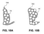
- FIGS. 10A and 10Bshow a target (VOI) from two different node positions.
- FIG. 10Ashows the VOI 700 a from a first position
- FIG. 10Bshows the VOI 700 b from a second position.
- the same VOIhas different shapes depending on the position.
- Both VOIs 700 a and 700 bare shown packed with circles 705 , but the VOI 700 b is more efficiently packed than the VOI 700 a .
- the shape of the packing object and its sizecorrespond to the collimator shape and size, and its position in the VOI corresponds to the beam orientation used to generate the candidate beams at each node position.
- FIGS. 11A-Eare exemplary screen shots of a user interface 800 for a treatment planning system. It will be appreciated that the user interface and screen shots may vary from those illustrated and described.
- images of the treatment regionare loaded into the treatment planning system.
- FIG. 11Bshows different 2D image slices containing cross sections of the target.
- the usermay enter various dose constraints, as described above, into the user interface 800 .
- FIG. 11Dshows a treatment plan for the target generated using an algorithm described herein.
- FIG. 11Eshows a treatment plan for the target, in which the collimator sizes are automatically selected. Alternatively, the user may be presented with suggested collimator size(s), and can accept and/or modify the suggested collimator size(s).
- FIG. 12illustrates a two-dimensional perspective of non-isocentric radiation beam delivery at a target region based on conformal planning. It should be noted that four beams, beam_ 1 901 , beam_ 2 902 , beam_ 3 903 , and beam_ 4 904 are illustrated in FIG. 12 only for ease of discussion and that an actual treatment plan may include more, or fewer, than four beams.
- the four beamsare representative of conformal planning, in which each beam passes through various points within target region 900 (e.g., the pathological anatomy).
- target region 900e.g., the pathological anatomy
- some beamsmay or may not intersect or converge at a common point, and although the four beams appear to intersect in the perspective of FIG. 12 , the beams may not intersect in their actual three-dimensional space.
- the radiation beamsneed only intersect with the target volume and do not necessarily converge on a single point, or isocenter, within the target 900 .
- conformal planningtakes advantage of an image-guided, robotic-based radiation treatment system (e.g., for performing radiosurgery) such as the CyberKnife® system, because the LINAC positioning mechanism (e.g., robotic arm 3012 of FIG. 14 ) can move around freely with multiple degrees of freedom, allowing the radiation beams of the LINAC to point anywhere in space.
- an image-guided, robotic-based radiation treatment systeme.g., for performing radiosurgery
- the LINAC positioning mechanisme.g., robotic arm 3012 of FIG. 14
- the LINAC positioning mechanisme.g., robotic arm 3012 of FIG. 14
- FIG. 13illustrates one embodiment of systems that may be used to perform radiation treatment in which features of the present invention may be implemented.
- system 4000may include a diagnostic imaging system 1000 , a treatment planning system 2000 , and a treatment delivery system 100 .
- Diagnostic imaging system 1000may be any system capable of producing medical diagnostic images of a treatment region in a patient that may be used for subsequent medical diagnosis, treatment planning and/or treatment delivery.
- diagnostic imaging system 1000may be a computed tomography (CT) system, a magnetic resonance imaging (MRI) system, a positron emission tomography (PET) system, an ultrasound system or the like.
- CTcomputed tomography
- MRImagnetic resonance imaging
- PETpositron emission tomography
- ultrasound systemor the like.
- diagnostic imaging system 1000may be discussed below at times in relation to a CT x-ray imaging modality. However, other imaging modalities such as those above may also be used.
- Diagnostic imaging system 1000includes an imaging source 1010 to generate an imaging beam (e.g., x-rays, ultrasonic waves, radio frequency waves, etc.) and an imaging detector 1020 to detect and receive the beam generated by imaging source 1010 , or a secondary beam or emission stimulated by the beam from the imaging source (e.g., in an MRI or PET scan).
- diagnostic imaging system 1000may include two or more diagnostic X-ray sources and two or more corresponding imaging detectors.
- two x-ray sourcesmay be disposed around a patient to be imaged, fixed at an angular separation from each other (e.g., 90 degrees, 45 degrees, etc.) and aimed through the patient toward (an) imaging detector(s) which may be diametrically opposed to the x-ray sources.
- an imaging detector(s)which may be diametrically opposed to the x-ray sources.
- a single large imaging detector, or multiple imaging detectors,may also be used that would be illuminated by each x-ray imaging source.
- other numbers and configurations of imaging sources and imaging detectorsmay be used.
- the imaging source 1010 and the imaging detector 1020are coupled to a digital processing system 1030 to control the imaging operation and process image data.
- Diagnostic imaging system 1000includes a bus or other means 1035 for transferring data and commands among digital processing system 1030 , imaging source 1010 and imaging detector 1020 .
- Digital processing system 1030may include one or more general-purpose processors (e.g., a microprocessor), special purpose processor such as a digital signal processor (DSP) or other type of device such as a controller or field programmable gate array (FPGA).
- DSPdigital signal processor
- FPGAfield programmable gate array
- Digital processing system 1030may also include other components (not shown) such as memory, storage devices, network adapters and the like.
- Digital processing system 1030may be configured to generate digital diagnostic images in a standard format, such as the DICOM (Digital Imaging and Communications in Medicine) format, for example. In other embodiments, digital processing system 1030 may generate other standard or non-standard digital image formats. Digital processing system 1030 may transmit diagnostic image files (e.g., the aforementioned DICOM formatted files) to treatment planning system 2000 over a data link 1500 , which may be, for example, a direct link, a local area network (LAN) link or a wide area network (WAN) link such as the Internet. In addition, the information transferred between systems may either be pulled or pushed across the communication medium connecting the systems, such as in a remote diagnosis or treatment planning configuration. In remote diagnosis or treatment planning, a user may utilize embodiments of the present invention to diagnose or treatment plan despite the existence of a physical separation between the system user and the patient.
- DICOMDigital Imaging and Communications in Medicine
- Treatment planning system 2000includes a processing device 2010 to receive and process image data.
- Processing device 2010may represent one or more general-purpose processors (e.g., a microprocessor), special purpose processor such as a digital signal processor (DSP) or other type of device such as a controller or field programmable gate array (FPGA).
- DSPdigital signal processor
- FPGAfield programmable gate array
- Processing device 2010may be configured to execute instructions for performing the operations of the treatment planning system 2000 discussed herein that, for example, may be loaded in processing device 2010 from storage 2030 and/or system memory 2020 .
- Treatment planning system 2000may also include system memory 2020 that may include a random access memory (RAM), or other dynamic storage devices, coupled to processing device 2010 by bus 2055 , for storing information and instructions to be executed by processing device 2010 .
- System memory 2020also may be used for storing temporary variables or other intermediate information during execution of instructions by processing device 2010 .
- System memory 2020may also include a read only memory (ROM) and/or other static storage device coupled to bus 2055 for storing static information and instructions for processing device 2010 .
- ROMread only memory
- Treatment planning system 2000may also include storage device 2030 , representing one or more storage devices (e.g., a magnetic disk drive or optical disk drive) coupled to bus 2055 for storing information and instructions.
- Storage device 2030may be used for storing instructions for performing the treatment planning methods discussed herein.
- Processing device 2010may also be coupled to a display device 2040 , such as a cathode ray tube (CRT) or liquid crystal display (LCD), for displaying information (e.g., a two-dimensional or three-dimensional representation of the VOI) to the user.
- a display device 2040such as a cathode ray tube (CRT) or liquid crystal display (LCD)
- An input device 2050such as a keyboard, may be coupled to processing device 2010 for communicating information and/or command selections to processing device 2010 .
- One or more other user input devicese.g., a mouse, a trackball or cursor direction keys
- treatment planning system 2000represents only one example of a treatment planning system, which may have many different configurations and architectures, which may include more components or fewer components than treatment planning system 2000 and which may be employed with the present invention. For example, some systems often have multiple buses, such as a peripheral bus, a dedicated cache bus, etc.
- the treatment planning system 2000may also include MIRIT (Medical Image Review and Import Tool) to support DICOM import (so images can be fused and targets delineated on different systems and then imported into the treatment planning system for planning and dose calculations), expanded image fusion capabilities that allow the user to treatment plan and view dose distributions on any one of various imaging modalities (e.g., MRI, CT, PET, etc.).
- MIRITMedical Image Review and Import Tool
- DICOM importso images can be fused and targets delineated on different systems and then imported into the treatment planning system for planning and dose calculations
- expanded image fusion capabilitiesthat allow the user to treatment plan and view dose distributions on any one of various imaging modalities (e.g., MRI,
- Treatment planning system 2000may share its database (e.g., data stored in storage device 2030 ) with a treatment delivery system, such as treatment delivery system 100 , so that it may not be necessary to export from the treatment planning system prior to treatment delivery.
- Treatment planning system 2000may be linked to treatment delivery system 100 via a data link 2500 , which may be a direct link, a LAN link or a WAN link as discussed above with respect to data link 1500 .
- data links 1500 and 2500are implemented as LAN or WAN connections, any of diagnostic imaging system 1000 , treatment planning system 2000 and/or treatment delivery system 100 may be in decentralized locations such that the systems may be physically remote from each other.
- any of diagnostic imaging system 2000 , treatment planning system 2000 and/or treatment delivery system 100may be integrated with each other in one or more systems.
- Treatment delivery system 100includes a therapeutic and/or surgical radiation source 105 to administer a prescribed radiation dose to a target volume in conformance with a treatment plan.
- Treatment delivery system 100may also include an imaging system 3020 to capture intra-treatment images of a patient volume (including the target volume) for registration or correlation with the diagnostic images described above in order to position the patient with respect to the radiation source.
- Treatment delivery system 100may also include a digital processing system 3030 to control radiation source 105 , imaging system 3020 , and a patient support device such as a treatment couch 110 .
- Digital processing system 3030may include one or more general-purpose processors (e.g., a microprocessor), special purpose processor such as a digital signal processor (DSP) or other type of device such as a controller or field programmable gate array (FPGA). Digital processing system 3030 may also include other components (not shown) such as memory, storage devices, network adapters and the like. Digital processing system 3030 may be coupled to radiation source 105 , imaging system 3020 and treatment couch 110 by a bus 3045 or other type of control and communication interface.
- general-purpose processorse.g., a microprocessor
- DSPdigital signal processor
- FPGAfield programmable gate array
- Digital processing system 3030may also include other components (not shown) such as memory, storage devices, network adapters and the like.
- Digital processing system 3030may be coupled to radiation source 105 , imaging system 3020 and treatment couch 110 by a bus 3045 or other type of control and communication interface.
- treatment delivery system 100may be an image-guided, robotic-based radiation treatment system (e.g., for performing radiosurgery) such as the CyberKnife® system developed by Accuray Incorporated of California.
- radiation source 105may be represented by a linear accelerator (LINAC) mounted on the end of a robotic arm 3012 having multiple (e.g., 5 or more) degrees of freedom in order to position the LINAC to irradiate a pathological anatomy (target region or volume) with beams delivered from many angles in an operating volume (e.g., a sphere) around the patient.
- LINAClinear accelerator
- Treatmentmay involve beam paths with a single isocenter (point of convergence), multiple isocenters, or with a non-isocentric approach (i.e., the beams need only intersect with the pathological target volume and do not necessarily converge on a single point, or isocenter, within the target as illustrated in FIG. 12 ).
- Treatmentcan be delivered in either a single session (mono-fraction) or in a small number of sessions as determined during treatment planning.
- radiation beamsmay be delivered according to the treatment plan without fixing the patient to a rigid, external frame to register the intra-operative position of the target volume with the position of the target volume during the pre-operative treatment planning phase.
- imaging system 3020may be represented by X-ray sources 120 A and 120 B and X-ray image detectors (imagers) 115 A and 115 B.
- two x-ray sources 120 A and 120 Bmay be nominally aligned to project imaging x-ray beams through a patient from two different angular positions (e.g., separated by 90 degrees, 45 degrees, etc.) and aimed through the patient on treatment couch 110 toward respective detectors 115 A and 115 B.
- a single large imagercan be used that would be illuminated by each x-ray imaging source.
- other numbers and configurations of imaging sources and imagersmay be used.
- Digital processing system 3030may implement algorithms to register (i.e., determine a common coordinate system for) images obtained from imaging system 3020 with pre-operative treatment planning images in order to align the patient on the treatment couch 110 within the treatment delivery system 100 , and to precisely position the radiation source with respect to the target volume.
- the treatment couch 110may be coupled to another robotic arm (not illustrated) having multiple (e.g., 5 or more) degrees of freedom.
- the couch armmay have five rotational degrees of freedom and one substantially vertical, linear degree of freedom.
- the couch armmay have six rotational degrees of freedom and one substantially vertical, linear degree of freedom or at least four rotational degrees of freedom.
- the couch armmay be vertically mounted to a column or wall, or horizontally mounted to pedestal, floor, or ceiling.
- the treatment couch 110may be a component of another mechanical mechanism, such as the Axum® treatment couch developed by Accuray Incorporated of California, or be another type of conventional treatment table known to those of ordinary skill in the art.
- treatmentmay refer generally to the effectuation of an operation controlled by the treatment planning system, such as the application of a beam (e.g., radiation, acoustic, etc.).
- a beame.g., radiation, acoustic, etc.
Landscapes
- Health & Medical Sciences (AREA)
- Engineering & Computer Science (AREA)
- Biomedical Technology (AREA)
- General Health & Medical Sciences (AREA)
- Pathology (AREA)
- Nuclear Medicine, Radiotherapy & Molecular Imaging (AREA)
- Radiology & Medical Imaging (AREA)
- Life Sciences & Earth Sciences (AREA)
- Animal Behavior & Ethology (AREA)
- Physics & Mathematics (AREA)
- Public Health (AREA)
- Veterinary Medicine (AREA)
- High Energy & Nuclear Physics (AREA)
- General Engineering & Computer Science (AREA)
- Spectroscopy & Molecular Physics (AREA)
- Radiation-Therapy Devices (AREA)
Abstract
Description
Claims (37)
Priority Applications (2)
| Application Number | Priority Date | Filing Date | Title |
|---|---|---|---|
| US11/731,115US7590219B2 (en) | 2006-04-07 | 2007-03-30 | Automatically determining a beam parameter for radiation treatment planning |
| PCT/US2007/008657WO2007117647A2 (en) | 2006-04-07 | 2007-04-06 | Automatically determining a beam parameter for radiation treatment planning |
Applications Claiming Priority (2)
| Application Number | Priority Date | Filing Date | Title |
|---|---|---|---|
| US79050306P | 2006-04-07 | 2006-04-07 | |
| US11/731,115US7590219B2 (en) | 2006-04-07 | 2007-03-30 | Automatically determining a beam parameter for radiation treatment planning |
Publications (2)
| Publication Number | Publication Date |
|---|---|
| US20080011945A1 US20080011945A1 (en) | 2008-01-17 |
| US7590219B2true US7590219B2 (en) | 2009-09-15 |
Family
ID=39149312
Family Applications (3)
| Application Number | Title | Priority Date | Filing Date |
|---|---|---|---|
| US11/731,146AbandonedUS20080123813A1 (en) | 2006-04-07 | 2007-03-30 | Automatic selection of multiple collimators |
| US11/731,115Active2027-10-25US7590219B2 (en) | 2006-04-07 | 2007-03-30 | Automatically determining a beam parameter for radiation treatment planning |
| US11/731,145AbandonedUS20080013687A1 (en) | 2006-04-07 | 2007-03-30 | Automatically determining size or shape of a radiation beam |
Family Applications Before (1)
| Application Number | Title | Priority Date | Filing Date |
|---|---|---|---|
| US11/731,146AbandonedUS20080123813A1 (en) | 2006-04-07 | 2007-03-30 | Automatic selection of multiple collimators |
Family Applications After (1)
| Application Number | Title | Priority Date | Filing Date |
|---|---|---|---|
| US11/731,145AbandonedUS20080013687A1 (en) | 2006-04-07 | 2007-03-30 | Automatically determining size or shape of a radiation beam |
Country Status (5)
| Country | Link |
|---|---|
| US (3) | US20080123813A1 (en) |
| EP (1) | EP2005443A2 (en) |
| JP (1) | JP2009533084A (en) |
| CN (1) | CN101410910A (en) |
| WO (3) | WO2007117647A2 (en) |
Cited By (48)
| Publication number | Priority date | Publication date | Assignee | Title |
|---|---|---|---|---|
| US7912178B2 (en) | 2006-10-16 | 2011-03-22 | Oraya Therapeutics, Inc. | Orthovoltage radiotherapy |
| US7912179B2 (en) | 2007-04-09 | 2011-03-22 | Oraya Therapeutics, Inc. | Orthovoltage radiosurgery |
| US20120014507A1 (en)* | 2010-07-16 | 2012-01-19 | Duke University | Automatic Generation of Patient-Specific Radiation Therapy Planning Parameters |
| US20120241635A1 (en)* | 2009-12-05 | 2012-09-27 | Gsi Helmholtzzentrum Für Schwerionenforschung Gmbh | Irradiation method and device for performing the method |
| US20120316423A1 (en)* | 2011-01-21 | 2012-12-13 | Headwater Partners Ii Llc | Imaging observation timing for assisting radiation treatment |
| US8363783B2 (en) | 2007-06-04 | 2013-01-29 | Oraya Therapeutics, Inc. | Method and device for ocular alignment and coupling of ocular structures |
| US8494116B2 (en) | 2007-12-23 | 2013-07-23 | Oraya Therapeutics, Inc. | Methods and devices for orthovoltage ocular radiotherapy and treatment planning |
| US8503609B2 (en) | 2007-12-23 | 2013-08-06 | Oraya Therapeutics, Inc. | Methods and devices for detecting, controlling, and predicting radiation delivery |
| US8506558B2 (en) | 2008-01-11 | 2013-08-13 | Oraya Therapeutics, Inc. | System and method for performing an ocular irradiation procedure |
| WO2013127005A1 (en)* | 2012-02-28 | 2013-09-06 | Dalhousie University | Reduced dose x-ray imaging |
| US8900113B2 (en) | 2011-01-21 | 2014-12-02 | Headwater Partners Ii Llc | Tracking of tumor location for targeted radiation treatment |
| US8948842B2 (en) | 2011-01-21 | 2015-02-03 | Headwater Partners Ii Llc | Radiation treatment with multiple imaging elements |
| US20150283697A1 (en)* | 2014-04-07 | 2015-10-08 | Daegu Gyeongbuk Institute Of Science And Technology | Robot |
| US9364687B2 (en) | 2011-01-21 | 2016-06-14 | Headwater Partners Ii Llc | Imaging observation timing based on radiation treatment system element delay |
| US20170036037A1 (en)* | 2014-04-30 | 2017-02-09 | Stc.Unm | Optimization methods for radiation therapy planning |
| US20170087382A1 (en)* | 2015-09-25 | 2017-03-30 | Varian Medical Systems International Ag | Apparatus and method using automatic generation of a base dose |
| US9895559B2 (en)* | 2014-04-07 | 2018-02-20 | Daegu Gyeongbuk Institute Of Science And Technology | Robot |
| US10071265B2 (en)* | 2014-04-07 | 2018-09-11 | Daegu Gyeongbuk Institute Of Science And Technology | Medical robot |
| US20190060674A1 (en)* | 2017-08-29 | 2019-02-28 | Sensus Healthcare, Inc. | Robotic iort x-ray radiation system with calibration well |
| US10398911B2 (en)* | 2015-09-25 | 2019-09-03 | Varian Medical Systems Internationl AG | Method and apparatus for using a multi-layer multi-leaf collimation system |
| US10449388B2 (en) | 2013-06-18 | 2019-10-22 | Duke University | Systems and methods for specifying treatment criteria and treatment parameters for patient specific radiation therapy planning |
| US10607802B2 (en) | 2017-03-31 | 2020-03-31 | Sensus Healthcare, Inc. | Three-dimensional beam forming X-ray source |
| US10646726B2 (en) | 2016-07-13 | 2020-05-12 | Sensus Healthcare, Inc. | Robotic intraoperative radiation therapy |
| US10918886B2 (en) | 2019-06-10 | 2021-02-16 | Varian Medical Systems, Inc. | Flash therapy treatment planning and oncology information system having dose rate prescription and dose rate mapping |
| US10940334B2 (en) | 2018-10-19 | 2021-03-09 | Sensus Healthcare, Inc. | Systems and methods for real time beam sculpting intra-operative-radiation-therapy treatment planning |
| US10960231B2 (en) | 2016-04-01 | 2021-03-30 | Varian Medical Systems, Inc. | Radiation therapy systems and methods |
| US11045667B2 (en) | 2017-07-18 | 2021-06-29 | Sensus Healthcare, Inc. | Real-time x-ray dosimetry in intraoperative radiation therapy |
| US11090508B2 (en) | 2019-03-08 | 2021-08-17 | Varian Medical Systems Particle Therapy Gmbh & Co. Kg | System and method for biological treatment planning and decision support |
| US11103727B2 (en) | 2019-03-08 | 2021-08-31 | Varian Medical Systems International Ag | Model based PBS optimization for flash therapy treatment planning and oncology information system |
| US11116995B2 (en) | 2019-03-06 | 2021-09-14 | Varian Medical Systems, Inc. | Radiation treatment planning based on dose rate |
| US11147985B2 (en)* | 2017-02-02 | 2021-10-19 | Koninklijke Philips N.V. | Warm start initialization for external beam radiotherapy plan optimization |
| US11291859B2 (en) | 2019-10-03 | 2022-04-05 | Varian Medical Systems, Inc. | Radiation treatment planning for delivering high dose rates to spots in a target |
| US11348755B2 (en) | 2018-07-25 | 2022-05-31 | Varian Medical Systems, Inc. | Radiation anode target systems and methods |
| US11478664B2 (en) | 2017-07-21 | 2022-10-25 | Varian Medical Systems, Inc. | Particle beam gun control systems and methods |
| US11534625B2 (en) | 2019-03-06 | 2022-12-27 | Varian Medical Systems, Inc. | Radiation treatment based on dose rate |
| US11541252B2 (en) | 2020-06-23 | 2023-01-03 | Varian Medical Systems, Inc. | Defining dose rate for pencil beam scanning |
| US20230057253A1 (en)* | 2020-09-29 | 2023-02-23 | Varian Medical Systems International Ag | Trajectory optimization using dose estimation and conflict detection |
| US11590364B2 (en) | 2017-07-21 | 2023-02-28 | Varian Medical Systems International Ag | Material inserts for radiation therapy |
| US11672491B2 (en) | 2018-03-30 | 2023-06-13 | Empyrean Medical Systems, Inc. | Validation of therapeutic radiation treatment |
| US11673003B2 (en) | 2017-07-21 | 2023-06-13 | Varian Medical Systems, Inc. | Dose aspects of radiation therapy planning and treatment |
| US11712579B2 (en) | 2017-07-21 | 2023-08-01 | Varian Medical Systems, Inc. | Range compensators for radiation therapy |
| US11766574B2 (en) | 2017-07-21 | 2023-09-26 | Varian Medical Systems, Inc. | Geometric aspects of radiation therapy planning and treatment |
| US11857805B2 (en) | 2017-11-16 | 2024-01-02 | Varian Medical Systems, Inc. | Increased beam output and dynamic field shaping for radiotherapy system |
| US11865361B2 (en) | 2020-04-03 | 2024-01-09 | Varian Medical Systems, Inc. | System and method for scanning pattern optimization for flash therapy treatment planning |
| US11957934B2 (en) | 2020-07-01 | 2024-04-16 | Siemens Healthineers International Ag | Methods and systems using modeling of crystalline materials for spot placement for radiation therapy |
| US11986677B2 (en) | 2017-07-21 | 2024-05-21 | Siemens Healthineers International Ag | Triggered treatment systems and methods |
| US12064645B2 (en) | 2020-07-02 | 2024-08-20 | Siemens Healthineers International Ag | Methods and systems used for planning radiation treatment |
| US12390662B2 (en) | 2020-04-02 | 2025-08-19 | Siemens Healthineers International Ag | System and method for proton therapy treatment planning with proton energy and spot optimization |
Families Citing this family (25)
| Publication number | Priority date | Publication date | Assignee | Title |
|---|---|---|---|---|
| EP1720173A1 (en)* | 2005-05-06 | 2006-11-08 | Deutsches Krebsforschungszentrum Stiftung des öffentlichen Rechts | Collimator for collimating a beam of high energy rays |
| US8920300B2 (en)* | 2007-09-19 | 2014-12-30 | Walter A. Roberts | Direct visualization robotic intra-operative radiation therapy device with radiation ablation capsule |
| JP2010029594A (en)* | 2008-07-31 | 2010-02-12 | Natl Inst Of Radiological Sciences | Corpuscular beam irradiating apparatus and treatment planning device |
| US8180020B2 (en) | 2008-10-23 | 2012-05-15 | Accuray Incorporated | Sequential optimizations for treatment planning |
| US10363437B2 (en)* | 2008-12-11 | 2019-07-30 | Varian Medical Systems International Ag | Real time treatment parameter algorithm for moving targets |
| US8982182B2 (en)* | 2010-03-01 | 2015-03-17 | Apple Inc. | Non-uniform spatial resource allocation for depth mapping |
| US9406411B2 (en) | 2011-02-08 | 2016-08-02 | Accuray Incorporated | Automatic calibration for device with controlled motion range |
| US9317969B2 (en)* | 2013-03-15 | 2016-04-19 | Varian Medical Systems, Inc. | Constructive anatomic geometry |
| KR101526115B1 (en)* | 2014-04-07 | 2015-06-04 | 재단법인대구경북과학기술원 | 3-dimensional emitting apparatus |
| CN107427689A (en)* | 2015-04-09 | 2017-12-01 | 三菱电机株式会社 | Therapy planning device and particle-beam therapeutic apparatus |
| US10729920B2 (en)* | 2015-10-02 | 2020-08-04 | Varian Medical Systems International Ag | Systems and methods for quantifying radiation beam conformity |
| US10881875B2 (en)* | 2016-03-09 | 2021-01-05 | Koninklijke Philips N.V. | Pre-optimization method for quick prediction of achievability of clinical goals in intensity modulated radiation therapy |
| US10456103B2 (en) | 2016-06-14 | 2019-10-29 | Shanghai United Imaging Healthcare Co., Ltd. | Unified trajectory generation process and system |
| US10744343B2 (en)* | 2017-04-28 | 2020-08-18 | Elekta Instrument Ab | Convex inverse planning method |
| US11458331B2 (en) | 2017-04-28 | 2022-10-04 | Elekta Instrument Ab | Convex inverse planning method |
| US11058895B2 (en)* | 2017-08-15 | 2021-07-13 | Daegu Gyeongbuk Institute Of Science And Technology | Collimator and medical robot including the same |
| WO2019081042A1 (en)* | 2017-10-27 | 2019-05-02 | Brainlab Ag | Planning method for multiple brain metastases based on iso-dose line prescriptions |
| WO2019127443A1 (en) | 2017-12-29 | 2019-07-04 | Shenzhen United Imaging Healthcare Co., Ltd. | System and method for synchronous motion optimization of device with moving components |
| EP3530319B1 (en)* | 2018-02-21 | 2025-01-22 | Elekta Instrument AB | Methods for inverse planning |
| KR102104961B1 (en)* | 2018-07-03 | 2020-04-27 | 고려대학교산학협력단 | Apparatus for alternating electric fields therapy using optimized algorithm |
| WO2021108684A1 (en)* | 2019-11-25 | 2021-06-03 | The Regents Of The University Of California | Systems and methods for dynamic control of radiation dose in radiation therapy |
| WO2022240894A1 (en)* | 2021-05-11 | 2022-11-17 | Celestial Oncology Inc. | Coupled robotic radiation therapy system |
| CN113491844B (en)* | 2021-07-30 | 2022-04-29 | 北京瑞尔世维医学研究有限公司 | A global surface radiation therapy system |
| US20240212822A1 (en)* | 2022-12-21 | 2024-06-27 | Siemens Healthineers International Ag | Systems and methods for optimizing radiotherapy planning using plan quality scores |
| CN116803449B (en) | 2023-06-20 | 2024-03-22 | 江苏瑞尔医疗科技有限公司 | A radiotherapy system based on multiple isocenters |
Citations (11)
| Publication number | Priority date | Publication date | Assignee | Title |
|---|---|---|---|---|
| US5278886A (en) | 1992-01-16 | 1994-01-11 | Hitachi Medical Corporation | Radiosurgery effecting position correction of collimator |
| JPH06233831A (en) | 1993-02-10 | 1994-08-23 | Hitachi Medical Corp | Stereotaxic radiotherapeutic device |
| US6044126A (en) | 1997-06-23 | 2000-03-28 | Ch&U De Lille | Process for automatically determining the configuration of a stereotactic radiosurgery helmet to which can be fitted a plurality of collimators focused on an irradiation isocenter |
| US6546073B1 (en) | 1999-11-05 | 2003-04-08 | Georgia Tech Research Corporation | Systems and methods for global optimization of treatment planning for external beam radiation therapy |
| WO2005058419A1 (en) | 2003-12-16 | 2005-06-30 | Elekta Ab (Publ) | Collimator system for a radiotherapy apparatus |
| US20060023842A1 (en) | 2004-07-28 | 2006-02-02 | General Electric Company | Single-leaf X-ray collimator |
| US20060067481A1 (en) | 2002-07-20 | 2006-03-30 | The University Of Surrey | Radiation collimation |
| US20060074292A1 (en) | 2004-09-30 | 2006-04-06 | Accuray, Inc. | Dynamic tracking of moving targets |
| US7096055B1 (en) | 1998-06-24 | 2006-08-22 | Achim Schweikard | Method to control delivery of radiation therapy |
| US20060203964A1 (en) | 2004-12-23 | 2006-09-14 | Nucletron B.V. | Method and device for calculating the radiation dose distribution for a radiation treatment system for the purpose of radiation therapy of an animal body |
| US20070297565A1 (en) | 2004-10-01 | 2007-12-27 | Wofford Mark G | System and method utilizing adaptive radiation therapy framework |
- 2007
- 2007-03-30USUS11/731,146patent/US20080123813A1/ennot_activeAbandoned
- 2007-03-30USUS11/731,115patent/US7590219B2/enactiveActive
- 2007-03-30USUS11/731,145patent/US20080013687A1/ennot_activeAbandoned
- 2007-04-06JPJP2009504332Apatent/JP2009533084A/enactivePending
- 2007-04-06CNCNA2007800115751Apatent/CN101410910A/enactivePending
- 2007-04-06WOPCT/US2007/008657patent/WO2007117647A2/enactiveApplication Filing
- 2007-04-06EPEP07774927Apatent/EP2005443A2/ennot_activeWithdrawn
- 2007-04-06WOPCT/US2007/008661patent/WO2007117650A2/enactiveApplication Filing
- 2007-04-06WOPCT/US2007/008656patent/WO2007117646A2/enactiveApplication Filing
Patent Citations (12)
| Publication number | Priority date | Publication date | Assignee | Title |
|---|---|---|---|---|
| US5278886A (en) | 1992-01-16 | 1994-01-11 | Hitachi Medical Corporation | Radiosurgery effecting position correction of collimator |
| JPH06233831A (en) | 1993-02-10 | 1994-08-23 | Hitachi Medical Corp | Stereotaxic radiotherapeutic device |
| US6044126A (en) | 1997-06-23 | 2000-03-28 | Ch&U De Lille | Process for automatically determining the configuration of a stereotactic radiosurgery helmet to which can be fitted a plurality of collimators focused on an irradiation isocenter |
| US7096055B1 (en) | 1998-06-24 | 2006-08-22 | Achim Schweikard | Method to control delivery of radiation therapy |
| US6546073B1 (en) | 1999-11-05 | 2003-04-08 | Georgia Tech Research Corporation | Systems and methods for global optimization of treatment planning for external beam radiation therapy |
| US6741674B2 (en) | 1999-11-05 | 2004-05-25 | Georgia Tech Research Corporation | Systems and methods for global optimization of treatment planning for external beam radiation therapy |
| US20060067481A1 (en) | 2002-07-20 | 2006-03-30 | The University Of Surrey | Radiation collimation |
| WO2005058419A1 (en) | 2003-12-16 | 2005-06-30 | Elekta Ab (Publ) | Collimator system for a radiotherapy apparatus |
| US20060023842A1 (en) | 2004-07-28 | 2006-02-02 | General Electric Company | Single-leaf X-ray collimator |
| US20060074292A1 (en) | 2004-09-30 | 2006-04-06 | Accuray, Inc. | Dynamic tracking of moving targets |
| US20070297565A1 (en) | 2004-10-01 | 2007-12-27 | Wofford Mark G | System and method utilizing adaptive radiation therapy framework |
| US20060203964A1 (en) | 2004-12-23 | 2006-09-14 | Nucletron B.V. | Method and device for calculating the radiation dose distribution for a radiation treatment system for the purpose of radiation therapy of an animal body |
Non-Patent Citations (5)
| Title |
|---|
| PCT International Preliminary Report on Patentability, PCT/US2007/008657 filed Apr. 6, 2007, mailed Oct. 16, 2008. |
| PCT International Search Report , International Application No. PCT/US 07/08656, Filed Apr. 6, 2007, Mailed Feb. 12, 2008, 4 Pages. |
| PCT International Search Report , International Application No. PCT/US 07/08657, Filed Apr. 6, 2007, Mailed Mar. 7, 2008, 5 Pages. |
| PCT Written Opinion of the International Searching Authority, International Application No. PCT/US 07/08656, Filed Apr. 6, 2007, Mailed Feb. 12, 2008, 6 Pages. |
| PCT Written Opinion of the International Searching Authority, International Application No. PCT/US 07/08657, Filed Apr. 6, 2007, Mailed Mar. 7, 2008, 4 Pages. |
Cited By (103)
| Publication number | Priority date | Publication date | Assignee | Title |
|---|---|---|---|---|
| US8320524B2 (en) | 2006-10-16 | 2012-11-27 | Oraya Therapeutics, Inc. | Orthovoltage radiotherapy |
| US8837675B2 (en) | 2006-10-16 | 2014-09-16 | Oraya Therapeutics, Inc. | Ocular radiosurgery |
| US8761336B2 (en) | 2006-10-16 | 2014-06-24 | Oraya Therapeutics, Inc. | Orthovoltage radiotherapy |
| US8611497B2 (en) | 2006-10-16 | 2013-12-17 | Oraya Therapeutics, Inc. | Portable orthovoltage radiotherapy |
| US8855267B2 (en) | 2006-10-16 | 2014-10-07 | Oraya Therapeutics, Inc. | Orthovoltage radiosurgery |
| US8995618B2 (en) | 2006-10-16 | 2015-03-31 | Oraya Therapeutics, Inc. | Portable orthovoltage radiotherapy |
| US8059784B2 (en) | 2006-10-16 | 2011-11-15 | Oraya Therapeutics, Inc. | Portable orthovoltage radiotherapy |
| US8073105B2 (en) | 2006-10-16 | 2011-12-06 | Oraya Therapeutics, Inc. | Ocular radiosurgery |
| US8094779B2 (en) | 2006-10-16 | 2012-01-10 | Oraya Therapeutics, Inc. | Orthovoltage radiotherapy |
| US7912178B2 (en) | 2006-10-16 | 2011-03-22 | Oraya Therapeutics, Inc. | Orthovoltage radiotherapy |
| US8180021B2 (en) | 2006-10-16 | 2012-05-15 | Oraya Therapeutics, Inc. | Orthovoltage radiotherapy |
| US8442185B2 (en) | 2006-10-16 | 2013-05-14 | Oraya Therapeutics, Inc. | Orthovoltage radiosurgery |
| US8189739B2 (en) | 2006-10-16 | 2012-05-29 | Oraya Therapeutics, Inc. | Orthovoltage radiotherapy |
| US9272161B2 (en) | 2006-12-13 | 2016-03-01 | Oraya Therapeutics, Inc. | Orthovoltage radiotherapy |
| US7961845B2 (en)* | 2006-12-13 | 2011-06-14 | Oraya Therapeutics, Inc. | Orthovoltage radiotherapy |
| US8238517B2 (en) | 2006-12-13 | 2012-08-07 | Oraya Therapeutics, Inc. | Orthovoltage radiotherapy |
| US8787524B2 (en) | 2006-12-13 | 2014-07-22 | Oraya Therapeutics, Inc. | Orthovoltage radiotherapy |
| US8295437B2 (en) | 2006-12-13 | 2012-10-23 | Oraya Therapeutics, Inc. | Orthovoltage radiotherapy |
| US8306186B2 (en) | 2006-12-13 | 2012-11-06 | Oraya Therapeutics, Inc. | Orthovoltage radiotherapy |
| US8229069B2 (en) | 2006-12-13 | 2012-07-24 | Oraya Therapeutics, Inc. | Orthovoltage radiotherapy |
| US8229073B2 (en) | 2006-12-13 | 2012-07-24 | Oraya Therapeutics, Inc. | Orthovoltage radiotherapy |
| US7978818B2 (en) | 2006-12-13 | 2011-07-12 | Oraya Therapeutics, Inc. | Orthovoltage radiotherapy |
| US7978819B2 (en) | 2006-12-13 | 2011-07-12 | Oraya Therapeutics, Inc. | Orthovoltage radiotherapy |
| US8457277B2 (en) | 2007-04-09 | 2013-06-04 | Oraya Therapeutics, Inc. | Orthovoltage radiosurgery |
| US8184772B2 (en) | 2007-04-09 | 2012-05-22 | Oraya Therapeutics, Inc. | Orthovoltage radiosurgery |
| US7953203B2 (en) | 2007-04-09 | 2011-05-31 | Oraya Therapeutics, Inc. | Orthovoltage radiosurgery |
| US7912179B2 (en) | 2007-04-09 | 2011-03-22 | Oraya Therapeutics, Inc. | Orthovoltage radiosurgery |
| US8923479B2 (en) | 2007-06-04 | 2014-12-30 | Oraya Therapeutics, Inc. | Method and device for ocular alignment and coupling of ocular structures |
| US8363783B2 (en) | 2007-06-04 | 2013-01-29 | Oraya Therapeutics, Inc. | Method and device for ocular alignment and coupling of ocular structures |
| US8630388B2 (en) | 2007-06-04 | 2014-01-14 | Oraya Therapeutics, Inc. | Method and device for ocular alignment and coupling of ocular structures |
| US8494116B2 (en) | 2007-12-23 | 2013-07-23 | Oraya Therapeutics, Inc. | Methods and devices for orthovoltage ocular radiotherapy and treatment planning |
| US8503609B2 (en) | 2007-12-23 | 2013-08-06 | Oraya Therapeutics, Inc. | Methods and devices for detecting, controlling, and predicting radiation delivery |
| US9025727B2 (en) | 2007-12-23 | 2015-05-05 | Oraya Therapeutics, Inc. | Methods and devices for orthovoltage ocular radiotherapy and treatment planning |
| US8848869B2 (en) | 2007-12-23 | 2014-09-30 | Oraya Therapeutics, Inc. | Methods and devices for detecting, controlling, and predicting radiation delivery |
| US8506558B2 (en) | 2008-01-11 | 2013-08-13 | Oraya Therapeutics, Inc. | System and method for performing an ocular irradiation procedure |
| US8920406B2 (en) | 2008-01-11 | 2014-12-30 | Oraya Therapeutics, Inc. | Device and assembly for positioning and stabilizing an eye |
| US8512236B2 (en) | 2008-01-11 | 2013-08-20 | Oraya Therapeutics, Inc. | System and method for positioning and stabilizing an eye |
| US9018593B2 (en)* | 2009-12-05 | 2015-04-28 | Gsi Helmholtzzentrum Fuer Schwerionenforschung Gmbh | Irradiation method and device for carrying out the method |
| US20120241635A1 (en)* | 2009-12-05 | 2012-09-27 | Gsi Helmholtzzentrum Für Schwerionenforschung Gmbh | Irradiation method and device for performing the method |
| US20120014507A1 (en)* | 2010-07-16 | 2012-01-19 | Duke University | Automatic Generation of Patient-Specific Radiation Therapy Planning Parameters |
| US8976929B2 (en)* | 2010-07-16 | 2015-03-10 | Duke University | Automatic generation of patient-specific radiation therapy planning parameters |
| US20120316423A1 (en)* | 2011-01-21 | 2012-12-13 | Headwater Partners Ii Llc | Imaging observation timing for assisting radiation treatment |
| US8948842B2 (en) | 2011-01-21 | 2015-02-03 | Headwater Partners Ii Llc | Radiation treatment with multiple imaging elements |
| US9283404B2 (en)* | 2011-01-21 | 2016-03-15 | Headwater Partners Ii Llc | Imaging observation timing for assisting radiation treatment |
| US9364687B2 (en) | 2011-01-21 | 2016-06-14 | Headwater Partners Ii Llc | Imaging observation timing based on radiation treatment system element delay |
| US9669236B2 (en) | 2011-01-21 | 2017-06-06 | Headwater Partners Ii Llc | Tracking of tumor location for targeted radiation treatment |
| US8900113B2 (en) | 2011-01-21 | 2014-12-02 | Headwater Partners Ii Llc | Tracking of tumor location for targeted radiation treatment |
| WO2013127005A1 (en)* | 2012-02-28 | 2013-09-06 | Dalhousie University | Reduced dose x-ray imaging |
| US11583698B2 (en) | 2013-06-18 | 2023-02-21 | Wake Forest University Health Sciences | Systems and methods for specifying treatment criteria and treatment parameters for patient specific radiation therapy planning |
| US10449388B2 (en) | 2013-06-18 | 2019-10-22 | Duke University | Systems and methods for specifying treatment criteria and treatment parameters for patient specific radiation therapy planning |
| US10071265B2 (en)* | 2014-04-07 | 2018-09-11 | Daegu Gyeongbuk Institute Of Science And Technology | Medical robot |
| US20150283697A1 (en)* | 2014-04-07 | 2015-10-08 | Daegu Gyeongbuk Institute Of Science And Technology | Robot |
| US9855446B2 (en)* | 2014-04-07 | 2018-01-02 | Daegu Gyeongbuk Institute Of Science And Technology | Robot |
| US9895559B2 (en)* | 2014-04-07 | 2018-02-20 | Daegu Gyeongbuk Institute Of Science And Technology | Robot |
| US9844684B2 (en)* | 2014-04-30 | 2017-12-19 | Stc.Unm | Optimization methods for radiation therapy planning |
| US20170036037A1 (en)* | 2014-04-30 | 2017-02-09 | Stc.Unm | Optimization methods for radiation therapy planning |
| US10252081B2 (en)* | 2015-09-25 | 2019-04-09 | Varian Medical Systems International Ag | Apparatus and method using automatic generation of a base dose |
| US11191978B2 (en) | 2015-09-25 | 2021-12-07 | Varian Medical Systems International Ag | Apparatus and method using automatic generation of a base dose |
| US10398911B2 (en)* | 2015-09-25 | 2019-09-03 | Varian Medical Systems Internationl AG | Method and apparatus for using a multi-layer multi-leaf collimation system |
| US20170087382A1 (en)* | 2015-09-25 | 2017-03-30 | Varian Medical Systems International Ag | Apparatus and method using automatic generation of a base dose |
| US10960231B2 (en) | 2016-04-01 | 2021-03-30 | Varian Medical Systems, Inc. | Radiation therapy systems and methods |
| US11529532B2 (en) | 2016-04-01 | 2022-12-20 | Varian Medical Systems, Inc. | Radiation therapy systems and methods |
| US10646726B2 (en) | 2016-07-13 | 2020-05-12 | Sensus Healthcare, Inc. | Robotic intraoperative radiation therapy |
| US11147985B2 (en)* | 2017-02-02 | 2021-10-19 | Koninklijke Philips N.V. | Warm start initialization for external beam radiotherapy plan optimization |
| US12027341B2 (en) | 2017-03-31 | 2024-07-02 | Empyrean Medical Systems, Inc. | Three-dimensional beam forming X-ray source |
| US10607802B2 (en) | 2017-03-31 | 2020-03-31 | Sensus Healthcare, Inc. | Three-dimensional beam forming X-ray source |
| US11521820B2 (en) | 2017-03-31 | 2022-12-06 | Empyrean Medical Systems, Inc. | Three-dimensional beam forming x-ray source |
| US12340968B2 (en) | 2017-03-31 | 2025-06-24 | Empyrean Medical Systems, Inc. | Three-dimensional beam forming X-ray source |
| US11045667B2 (en) | 2017-07-18 | 2021-06-29 | Sensus Healthcare, Inc. | Real-time x-ray dosimetry in intraoperative radiation therapy |
| US11986677B2 (en) | 2017-07-21 | 2024-05-21 | Siemens Healthineers International Ag | Triggered treatment systems and methods |
| US11590364B2 (en) | 2017-07-21 | 2023-02-28 | Varian Medical Systems International Ag | Material inserts for radiation therapy |
| US11673003B2 (en) | 2017-07-21 | 2023-06-13 | Varian Medical Systems, Inc. | Dose aspects of radiation therapy planning and treatment |
| US11478664B2 (en) | 2017-07-21 | 2022-10-25 | Varian Medical Systems, Inc. | Particle beam gun control systems and methods |
| US12145006B2 (en) | 2017-07-21 | 2024-11-19 | Varian Medical Systems, Inc. | Particle beam gun control systems and methods |
| US11712579B2 (en) | 2017-07-21 | 2023-08-01 | Varian Medical Systems, Inc. | Range compensators for radiation therapy |
| US12290704B2 (en) | 2017-07-21 | 2025-05-06 | Siemens Healthinees International Ag | Dose aspects of radiation therapy planning and treatment |
| US11766574B2 (en) | 2017-07-21 | 2023-09-26 | Varian Medical Systems, Inc. | Geometric aspects of radiation therapy planning and treatment |
| US10350437B2 (en)* | 2017-08-29 | 2019-07-16 | Sensus Healthcare, Inc. | Robotic IORT x-ray radiation system with calibration well |
| US20190060674A1 (en)* | 2017-08-29 | 2019-02-28 | Sensus Healthcare, Inc. | Robotic iort x-ray radiation system with calibration well |
| US11857805B2 (en) | 2017-11-16 | 2024-01-02 | Varian Medical Systems, Inc. | Increased beam output and dynamic field shaping for radiotherapy system |
| US11672491B2 (en) | 2018-03-30 | 2023-06-13 | Empyrean Medical Systems, Inc. | Validation of therapeutic radiation treatment |
| US11854761B2 (en) | 2018-07-25 | 2023-12-26 | Varian Medical Systems, Inc. | Radiation anode target systems and methods |
| US11348755B2 (en) | 2018-07-25 | 2022-05-31 | Varian Medical Systems, Inc. | Radiation anode target systems and methods |
| US10940334B2 (en) | 2018-10-19 | 2021-03-09 | Sensus Healthcare, Inc. | Systems and methods for real time beam sculpting intra-operative-radiation-therapy treatment planning |
| US11116995B2 (en) | 2019-03-06 | 2021-09-14 | Varian Medical Systems, Inc. | Radiation treatment planning based on dose rate |
| US12161881B2 (en) | 2019-03-06 | 2024-12-10 | Siemens Healthineers International Ag | Radiation treatment based on dose rate |
| US11534625B2 (en) | 2019-03-06 | 2022-12-27 | Varian Medical Systems, Inc. | Radiation treatment based on dose rate |
| US11090508B2 (en) | 2019-03-08 | 2021-08-17 | Varian Medical Systems Particle Therapy Gmbh & Co. Kg | System and method for biological treatment planning and decision support |
| US11103727B2 (en) | 2019-03-08 | 2021-08-31 | Varian Medical Systems International Ag | Model based PBS optimization for flash therapy treatment planning and oncology information system |
| US11554271B2 (en) | 2019-06-10 | 2023-01-17 | Varian Medical Systems, Inc | Flash therapy treatment planning and oncology information system having dose rate prescription and dose rate mapping |
| US11865364B2 (en) | 2019-06-10 | 2024-01-09 | Varian Medical Systems, Inc. | Flash therapy treatment planning and oncology information system having dose rate prescription and dose rate mapping |
| US12311198B2 (en) | 2019-06-10 | 2025-05-27 | Siemens Healthineers International Ag | Flash therapy treatment planning and oncology information system having dose rate prescription and dose rate mapping |
| US10918886B2 (en) | 2019-06-10 | 2021-02-16 | Varian Medical Systems, Inc. | Flash therapy treatment planning and oncology information system having dose rate prescription and dose rate mapping |
| US11986672B2 (en) | 2019-10-03 | 2024-05-21 | Siemens Healthineers International Ag | Radiation treatment planning for delivering high dose rates to spots in a target |
| US12023519B2 (en) | 2019-10-03 | 2024-07-02 | Siemens Healthineers International Ag | Radiation treatment planning for delivering high dose rates to spots in a target |
| US11291859B2 (en) | 2019-10-03 | 2022-04-05 | Varian Medical Systems, Inc. | Radiation treatment planning for delivering high dose rates to spots in a target |
| US12390662B2 (en) | 2020-04-02 | 2025-08-19 | Siemens Healthineers International Ag | System and method for proton therapy treatment planning with proton energy and spot optimization |
| US11865361B2 (en) | 2020-04-03 | 2024-01-09 | Varian Medical Systems, Inc. | System and method for scanning pattern optimization for flash therapy treatment planning |
| US11541252B2 (en) | 2020-06-23 | 2023-01-03 | Varian Medical Systems, Inc. | Defining dose rate for pencil beam scanning |
| US11957934B2 (en) | 2020-07-01 | 2024-04-16 | Siemens Healthineers International Ag | Methods and systems using modeling of crystalline materials for spot placement for radiation therapy |
| US12064645B2 (en) | 2020-07-02 | 2024-08-20 | Siemens Healthineers International Ag | Methods and systems used for planning radiation treatment |
| US20230057253A1 (en)* | 2020-09-29 | 2023-02-23 | Varian Medical Systems International Ag | Trajectory optimization using dose estimation and conflict detection |
| US12324929B2 (en)* | 2020-09-29 | 2025-06-10 | Siemens Healthineers International Ag | Trajectory optimization using dose estimation and conflict detection |
Also Published As
| Publication number | Publication date |
|---|---|
| WO2007117650A2 (en) | 2007-10-18 |
| WO2007117650A3 (en) | 2008-05-08 |
| WO2007117647A2 (en) | 2007-10-18 |
| WO2007117646A3 (en) | 2008-04-10 |
| WO2007117647A3 (en) | 2008-05-15 |
| US20080013687A1 (en) | 2008-01-17 |
| US20080011945A1 (en) | 2008-01-17 |
| CN101410910A (en) | 2009-04-15 |
| EP2005443A2 (en) | 2008-12-24 |
| WO2007117646A2 (en) | 2007-10-18 |
| JP2009533084A (en) | 2009-09-17 |
| US20080123813A1 (en) | 2008-05-29 |
Similar Documents
| Publication | Publication Date | Title |
|---|---|---|
| US7590219B2 (en) | Automatically determining a beam parameter for radiation treatment planning | |
| US11511132B2 (en) | Tumor tracking during radiation treatment using ultrasound imaging | |
| US7266176B2 (en) | Workspace optimization for radiation treatment delivery system | |
| US7593505B2 (en) | Method for automatic anatomy-specific treatment planning protocols based on historical integration of previously accepted plans | |
| US7801349B2 (en) | Automatic generation of an envelope of constraint points for inverse planning | |
| US7693257B2 (en) | Treatment delivery optimization | |
| US7477722B2 (en) | Imaging geometry for image-guided radiosurgery | |
| US7298819B2 (en) | Flexible treatment planning | |
| US8077936B2 (en) | Treatment planning software and corresponding user interface | |
| Kilby et al. | A technical overview of the CyberKnife system | |
| EP1905482A1 (en) | Radiation treatment planning using four-dimensional imaging data | |
| WO2006130862A2 (en) | Generating a volume of interest using a dose isocontour | |
| EP3875147B1 (en) | Treatment planning |
Legal Events
| Date | Code | Title | Description |
|---|---|---|---|
| AS | Assignment | Owner name:ACCURAY INCORPORATED, CALIFORNIA Free format text:ASSIGNMENT OF ASSIGNORS INTEREST;ASSIGNORS:MAURER, JR., CALVIN R.;WEST, JAY B.;ALLISON, JOHN W.;REEL/FRAME:019553/0073 Effective date:20070705 | |
| STCF | Information on status: patent grant | Free format text:PATENTED CASE | |
| FPAY | Fee payment | Year of fee payment:4 | |
| AS | Assignment | Owner name:CERBERUS BUSINESS FINANCE, LLC, AS COLLATERAL AGENT, NEW YORK Free format text:ASSIGNMENT FOR SECURITY - PATENTS;ASSIGNORS:ACCURAY INCORPORATED;TOMOTHERAPY INCORPORATED;REEL/FRAME:037513/0170 Effective date:20160111 Owner name:CERBERUS BUSINESS FINANCE, LLC, AS COLLATERAL AGEN Free format text:ASSIGNMENT FOR SECURITY - PATENTS;ASSIGNORS:ACCURAY INCORPORATED;TOMOTHERAPY INCORPORATED;REEL/FRAME:037513/0170 Effective date:20160111 | |
| FPAY | Fee payment | Year of fee payment:8 | |
| AS | Assignment | Owner name:MIDCAP FUNDING IV TRUST (AS SUCCESSOR BY ASSIGNMENT FROM MIDCAP FINANCIAL TRUST), MARYLAND Free format text:SECURITY INTEREST;ASSIGNORS:ACCURAY INCORPORATED;TOMOTHERAPY INCORPORATED;REEL/FRAME:042826/0358 Effective date:20170614 Owner name:ACCURAY INCORPORATED, CALIFORNIA Free format text:RELEASE BY SECURED PARTY;ASSIGNOR:CERBERUS BUSINESS FINANCE, LLC. AS COLLATERAL AGENT;REEL/FRAME:042821/0580 Effective date:20170614 Owner name:TOMOTHERAPY INCORPORATED, CALIFORNIA Free format text:RELEASE BY SECURED PARTY;ASSIGNOR:CERBERUS BUSINESS FINANCE, LLC. AS COLLATERAL AGENT;REEL/FRAME:042821/0580 Effective date:20170614 Owner name:MIDCAP FUNDING IV TRUST (AS SUCCESSOR BY ASSIGNMEN Free format text:SECURITY INTEREST;ASSIGNORS:ACCURAY INCORPORATED;TOMOTHERAPY INCORPORATED;REEL/FRAME:042826/0358 Effective date:20170614 | |
| AS | Assignment | Owner name:MIDCAP FINANCIAL TRUST, MARYLAND Free format text:SECURITY INTEREST;ASSIGNORS:ACCURAY INCORPORATED;TOMOTHERAPY INCORPORATED;REEL/FRAME:044910/0685 Effective date:20171215 | |
| AS | Assignment | Owner name:MIDCAP FUNDING IV TRUST, AS SUCCESSOR TO EXISTING Free format text:ASSIGNMENT OF SECURITY AGREEMENTS;ASSIGNOR:MIDCAP FUNDING X TRUST (AS SUCCESSOR BY ASSIGNMENT FROM MIDCAP FUNDING IV TRUST, AS SUCCESSOR BY ASSIGNMENT FROM MIDCAP FINANCIAL TRUST), AS EXISTING ADMINISTRATIVE AGENT;REEL/FRAME:048481/0804 Effective date:20190221 Owner name:MIDCAP FUNDING IV TRUST, AS SUCCESSOR TO EXISTING ADMINISTRATIVE AGENT, MARYLAND Free format text:ASSIGNMENT OF SECURITY AGREEMENTS;ASSIGNOR:MIDCAP FUNDING X TRUST (AS SUCCESSOR BY ASSIGNMENT FROM MIDCAP FUNDING IV TRUST, AS SUCCESSOR BY ASSIGNMENT FROM MIDCAP FINANCIAL TRUST), AS EXISTING ADMINISTRATIVE AGENT;REEL/FRAME:048481/0804 Effective date:20190221 | |
| MAFP | Maintenance fee payment | Free format text:PAYMENT OF MAINTENANCE FEE, 12TH YEAR, LARGE ENTITY (ORIGINAL EVENT CODE: M1553); ENTITY STATUS OF PATENT OWNER: LARGE ENTITY Year of fee payment:12 | |
| AS | Assignment | Owner name:SILICON VALLEY BANK, AS ADMINISTRATIVE AND COLLATERAL AGENT, CALIFORNIA Free format text:SECURITY INTEREST;ASSIGNORS:ACCURAY INCORPORATED;TOMOTHERAPY INCORPORATED;REEL/FRAME:056247/0001 Effective date:20210514 | |
| AS | Assignment | Owner name:ACCURAY INCORPORATED, CALIFORNIA Free format text:RELEASE BY SECURED PARTY;ASSIGNOR:MIDCAP FUNDING IV TRUST (AS SUCCESSOR BY ASSIGNMENT FROM MIDCAP FUNDING X TRUST, AS SUCCESSOR BY ASSIGNMENT FROM MIDCAP FUNDING IV TRUST, AS SUCCESSOR BY ASSIGNMENT FROM MIDCAP FINANCIAL TRUST);REEL/FRAME:056318/0559 Effective date:20210514 Owner name:TOMOTHERAPY INCORPORATED, CALIFORNIA Free format text:RELEASE BY SECURED PARTY;ASSIGNOR:MIDCAP FUNDING IV TRUST (AS SUCCESSOR BY ASSIGNMENT FROM MIDCAP FUNDING X TRUST, AS SUCCESSOR BY ASSIGNMENT FROM MIDCAP FUNDING IV TRUST, AS SUCCESSOR BY ASSIGNMENT FROM MIDCAP FINANCIAL TRUST);REEL/FRAME:056318/0559 Effective date:20210514 Owner name:ACCURAY INCORPORATED, CALIFORNIA Free format text:RELEASE BY SECURED PARTY;ASSIGNOR:MIDCAP FINANCIAL TRUST;REEL/FRAME:056318/0751 Effective date:20210514 Owner name:TOMOTHERAPY INCORPORATED, CALIFORNIA Free format text:RELEASE BY SECURED PARTY;ASSIGNOR:MIDCAP FINANCIAL TRUST;REEL/FRAME:056318/0751 Effective date:20210514 | |
| AS | Assignment | Owner name:ACCURAY INCORPORATED, WISCONSIN Free format text:RELEASE BY SECURED PARTY;ASSIGNOR:FIRST-CITIZENS BANK & TRUST COMPANY;REEL/FRAME:071638/0034 Effective date:20250606 | |
| AS | Assignment | Owner name:ACCURAY LLC, WISCONSIN Free format text:ASSIGNMENT OF ASSIGNORS INTEREST;ASSIGNOR:ACCURAY INCORPORATED;REEL/FRAME:072421/0584 Effective date:20250805 |