US7590052B2 - System and method for providing telecommunications service using a wireless link - Google Patents
System and method for providing telecommunications service using a wireless linkDownload PDFInfo
- Publication number
- US7590052B2 US7590052B2US10/822,439US82243904AUS7590052B2US 7590052 B2US7590052 B2US 7590052B2US 82243904 AUS82243904 AUS 82243904AUS 7590052 B2US7590052 B2US 7590052B2
- Authority
- US
- United States
- Prior art keywords
- radio
- interface unit
- connect
- cross
- digital
- Prior art date
- Legal status (The legal status is an assumption and is not a legal conclusion. Google has not performed a legal analysis and makes no representation as to the accuracy of the status listed.)
- Expired - Fee Related, expires
Links
- 238000000034methodMethods0.000titleabstractdescription10
- 238000009826distributionMethods0.000claimsabstractdescription84
- 230000003287optical effectEffects0.000claimsabstractdescription34
- RYGMFSIKBFXOCR-UHFFFAOYSA-NCopperChemical compound[Cu]RYGMFSIKBFXOCR-UHFFFAOYSA-N0.000claimsabstractdescription16
- 239000010949copperSubstances0.000claimsabstractdescription15
- 229910052802copperInorganic materials0.000claimsabstractdescription15
- 239000000835fiberSubstances0.000claimsdescription16
- 238000004891communicationMethods0.000claimsdescription15
- 238000012360testing methodMethods0.000description27
- 238000010586diagramMethods0.000description10
- 230000005540biological transmissionEffects0.000description9
- 230000006870functionEffects0.000description9
- 230000007613environmental effectEffects0.000description7
- 238000006243chemical reactionMethods0.000description5
- OKTJSMMVPCPJKN-UHFFFAOYSA-NCarbonChemical compound[C]OKTJSMMVPCPJKN-UHFFFAOYSA-N0.000description3
- 229910052799carbonInorganic materials0.000description3
- 230000001066destructive effectEffects0.000description3
- 238000005516engineering processMethods0.000description3
- 230000001939inductive effectEffects0.000description3
- 238000009434installationMethods0.000description3
- 238000012545processingMethods0.000description3
- 239000007787solidSubstances0.000description3
- 238000004378air conditioningMethods0.000description2
- 230000015556catabolic processEffects0.000description2
- 230000003750conditioning effectEffects0.000description2
- 238000006731degradation reactionMethods0.000description2
- 238000010438heat treatmentMethods0.000description2
- 239000013307optical fiberSubstances0.000description2
- 230000003190augmentative effectEffects0.000description1
- 101150080418ddp-1 geneProteins0.000description1
- 230000001934delayEffects0.000description1
- 238000013461designMethods0.000description1
- 238000005315distribution functionMethods0.000description1
- 239000000284extractSubstances0.000description1
- 239000000203mixtureSubstances0.000description1
- 230000009131signaling functionEffects0.000description1
- 238000001228spectrumMethods0.000description1
- 230000001360synchronised effectEffects0.000description1
- 238000010998test methodMethods0.000description1
Images


Classifications
- H—ELECTRICITY
- H04—ELECTRIC COMMUNICATION TECHNIQUE
- H04W—WIRELESS COMMUNICATION NETWORKS
- H04W84/00—Network topologies
- H04W84/02—Hierarchically pre-organised networks, e.g. paging networks, cellular networks, WLAN [Wireless Local Area Network] or WLL [Wireless Local Loop]
- H04W84/10—Small scale networks; Flat hierarchical networks
- H04W84/14—WLL [Wireless Local Loop]; RLL [Radio Local Loop]
Definitions
- This inventionrelates to telecommunications systems and more particularly to systems for connecting users in a service area to telecommunications service.
- COcentral office
- Telephone service providerstypically deploy the cable by connecting cables having successively lower capacities between the CO and the customer location.
- Cables with a first capacitysuch as for example, DS3 cable
- a DS3 cablecan carry a DS3 signal, which is a digital telephone signal that transmits at 44.736 Mbs.
- a DS3 cableis capable of carrying 672 pulse code modulation (PCM) voice channels.
- PCMpulse code modulation
- the DS3 cablemay be divided into several cables, which can carry 96 voice channels, or DS1 cables, which can carry 24 voice channels.
- the lower capacity cablesbranch out from the service area interface to different areas such that each DS1 cable serves a group of customers.
- DS1 cablesextend to a terminal from which drops are made to a network interface at a customer's location.
- the DS1 signalscan be carried on either optical or copper cables.
- DS3 signalsare carried by optical cables. Signals having higher capacities may be carried by optical, coaxial or by radio or wave-guides.
- the cablesare typically buried, or carried in underground conduits, although copper cables may be supported on telephone poles.
- the cablesterminate at the service area interfaces or at the terminals in structures that are built by the service providers.
- the structuresmay be huts, which have facilities for environmental conditioning such as power, fans, heating and air conditioning.
- the service providersmay also build cabinets, which are lower cost structures that are typically used for cross-connections and electronic equipment.
- FIG. 1is a block diagram of a telecommunications network illustrating the distribution of telecommunications service from the central office to local subscribers using wireless links;
- FIG. 2is a block diagram of a local distribution system according to a preferred embodiment
- FIG. 3is a block diagram of a first example of a local distribution system in the telecommunications network in FIG. 1 ;
- FIG. 4is a block diagram of a second example of a local distribution system in the telecommunications network in FIG. 1 ;
- FIG. 5is a block diagram of a third example of a local distribution system in the telecommunications network in FIG. 1 ;
- FIG. 6is a block diagram of a fourth example of a local distribution system in the telecommunications network in FIG. 1 ;
- FIG. 7is a block diagram of an alternative embodiment of the telecommunications network system FIG. 1 .
- FIG. 1is a block diagram of a telecommunications network 5 of the type in which the present invention finds advantageous use.
- the network 5 in FIG. 1includes a public switched telephone network (PSTN) 24 connected to a central office 26 by an interoffice telephone trunk 25 .
- PSTNpublic switched telephone network
- the central office 26includes central office switches for routing telephone connections to and from telephone service subscribers in a central office service area 10 .
- the central office 26is connected to a first local distribution system 6 , a local second distribution system 7 , and a local third distribution system 8 .
- the first local distribution system 6provides telephone service to users in a first service area 12 .
- the second local distribution system 7provides telephone service to users in a second service area 20 and a third service area 22 .
- the second local distribution system 7also connects the central office 26 to the third local distribution system 8 .
- the third local distribution system 8provides telephone connections to users in a fourth service area 14 , a fifth service area 16 and a sixth service area 18 .
- the central office switches in the central office 26typically includes information regarding telephone users that are connected in a major service area.
- the switchesuse the information to route calls between users in the PSTN 24 and users in the major service area 10 .
- the switchesmay also monitor the usage of telephone services by the users and perform or facilitate auxiliary telecommunications services to which the user may subscribe (e.g. call waiting, voice mail, call forwarding, etc.).
- the local distribution systems 6 , 7 , 8include connecting equipment that provides connections from the subscribers in the service areas to the central office 26 .
- the connecting equipmentwhich is described further below with reference to FIGS. 2-4 , includes telephone line distribution equipment such as multiplexing equipment and cross-connect panels, and telephone lines or cables, that provides connections between the users and the central office 26 .
- the telephone lines, or cablesmay include copper wire or optical links. In a preferred embodiment, the telephone lines also include radio links.
- the telephone line distribution equipmentmay be enclosed in huts or cabinets.
- the telecommunications devices used by the usersmay be connected directly to the connecting equipment in the huts or cabinets. Huts and cabinets may also be connected to each other to provide a fan out of service capacity that extends the central office service area 10 .
- Huts and cabinetsare structures that are built to house telecommunications equipment. Huts are typically larger than cabinets, being large enough to include one or more shelves of equipment. Huts may include environmental conditioning equipment such as, fans, air conditioning, heating and a power connection. Cabinets may only be large enough to provide an enclosure for the equipment that is not sensitive to environment conditions, but could also house fans. Huts and cabinets are well known in the art and require no further description.
- the first local distribution system 6includes a cabinet 28 connected to the central office 26 via an optical fiber 30 .
- the cabinet 28is connected to a second cabinet 32 via a radio link 50 .
- the radio link 50is implemented using a first temporary radio tower 50 a and a second temporary radio tower 50 b .
- the radiosmay be placed in cabinets, on pallets, skids or wheeled carts, and may be re-used once a permanent link has been installed.
- the usersaccess the telephone systems from customer premises equipment (CPE) on their premises.
- the CPE of the users in the service area 12are connected to the cabinet 32 by user connections 12 a .
- the user connections 12 atypically include twisted pair wires although other types of connections maybe used such as coaxial cable, fiber-optic cable, etc.
- the connections from the user CPE the central office 26form a digital loop carrier.
- the first local distribution system 6employs the temporary radio link 50 between the first temporary radio tower 50 a and the second temporary radio tower 50 b .
- the temporary radio link 50may be employed when the users in the service area 12 require telecommunications service before a cable can be buried between the first cabinet 28 and the second cabinet 32 .
- Another advantageis that the radio equipment is reusable. Once a permanent cable is deployed, the temporary radio link 50 may be removed and implemented elsewhere.
- the second local distribution system 7includes a first hut 36 that is connected to a second hut 38 via a DS1 line 54 .
- the first hut 36communicates with the central office 26 over the third radio link 52 .
- the first hut 36includes connections to users in the third service area 22 and a connection by an optical cable 70 to a third hut 40 in the third local distribution system 8 .
- the third hut 40is connected to a fourth hut 42 via a radio link 56 .
- the fourth hut 42is connected to a third cabinet 48 for connecting to the users in the fourth service area 14 .
- the third hut 40is also connected to a fifth hut 44 via a radio link 58 and to a fourth cabinet 46 via a radio link 60 .
- the radio links 56 , 58 , 60 from the hut 40are made using respective antennas on the radio tower 62 .
- the capacity or, maximum number of users connected in the local distribution systems local distribution systems 6 , 7 , 8may be determined by the capacity of the connecting medium (e.g. DS1, DS3, etc.), the capacity of the equipment used in the huts or the cabinets and by desired performance characteristics.
- the connecting mediume.g. DS1, DS3, etc.
- the capacity of the connecting mediamay be maximized by the use of optical fiber.
- the optical links 30 , 70 used in a telecommunications network 5may include a Synchronous Optical Network (SONET) fiber-optic cable at OC-1, OC-3 or OC-9 levels having line rates of 52 Mb/s, 155 Mb/s, and 466 Mb/s, respectively.
- SONETSynchronous Optical Network
- the connecting equipment in the huts and cabinetsmay be configured to divide links into lower capacity links.
- the optical link 70 connecting the first hut 36 with the third hut 40may be a n-OC-3 links, where n is determined according to the required capacity.
- the first hut 36may provide other lower capacity links in addition to, for example, a DS1 link 54 .
- the radio links 50 , 52 , 56 , 58 , 60are preferably microwave radio links, although any suitable wireless connection may be used.
- the microwave radio signalis preferably a radio signal that is licensed by the Federal Communications Commission (FCC). An unlicensed signal may also be used, if speed of deployment is important in a particular installation, preferably with a spread spectrum modulation technique
- the service areas 12 , 14 , 16 , 18 , 20 and 22comprise the central office service area 10 .
- the service areasmay be areas that are still growing. Each time a new user is added, it must be connected to the central office 26 via its local distribution system. As users are added to a service area, the capacity of the local distribution system may be reached such that new users may no longer be added.
- Telecommunications service providersmay either increase the capacity of the local distribution system, or build a new local distribution system.
- New local distribution systemsare typically built in the major service areas 10 expands to include a new service area.
- One advantage of the present inventionis that new local distributions systems may be deployed in a relatively short amount of time.
- the telecommunications service providercan build a new local distribution system by building huts or cabinets and by erecting radio towers, and then connecting the users to the huts or cabinets. It would not be necessary to bury cable other than the cables connected the users in the service area.
- FIG. 2is a block diagram for a telecommunications distribution enclosure 100 of the type that may be used in the telecommunications network 5 in FIG. 1 .
- Any suitable structure containing connecting equipmentmay be used as the enclosure 100 .
- Suitable structuresmay include huts and cabinets.
- the enclosure 100 in FIG. 2shows the functions and types of equipment that may be used in the local distribution systems in FIG. 1 .
- the connecting equipmentimplements digital loop carrier connections in segments between the central office 26 and the telecommunications devices, or CPE's on the customer premises.
- wireless digital loop carriercan interface with other types of transmission systems such as high bit-rate digital subscriber lines (HDSL), T-carrier or fiber-optic systems.
- Local distribution systemsmay also mix the types of connections in one enclosure.
- the enclosure 100includes connecting equipment for communicating by radio at a radio link 103 at the radio tower 102 , by fiber-optic cable at a fiber-optic outside plant 122 and by electrical signals at a copper cable outside plant 124 .
- the connecting equipment in enclosure 100is connected to the central office (i.e., office-side connection) and one or more connections to either other enclosures or subscribers (i.e., subscribers-side connection).
- the office-side connection and the subscriber-side connectionsmay be of any type, however, a higher capacity medium such as fiber-optic cable or radio is preferable.
- a primary function of the connecting equipmentis to distribute higher capacity office-side connections to lower, or the same, capacity subscriber-side connections.
- the radio link 103is the office-side connection; and the fiber outside plant 122 and copper outside plant 124 are subscriber-side connections.
- the radio tower 102may be connected on the subscriber-side and one of the other outside plants 122 , 124 may be connected to the office-side of the enclosure 100 .
- the connecting equipment in enclosure 100may be configured in a variety of different ways according to the type of equipment connected to it, as well as plans for increasing capacity on the subscribers side.
- the cross-connect panelsmay branch out on the subscribers side and connect to other cross-connection systems that connect on a subscribers side to other distribution systems or directly to subscribers.
- the radio side cross-connect 112may connect only to the electrical side cross-connect panel 116 for connecting DS0 lines directly to the subscribers at the outside plant 124 .
- a radio tower 102may be connected to one of several types of radios via a radio link 103 which may be a wave guide or a cable.
- An optical radio 104 amay be used to connect to an optical/electrical converter 117 which connects to a fiber-optic cross-connect 118 by a fiber-optic cable 105 .
- the optical radio 104may communicate at SONET OC-1, OC-3, OC-9, or OC-12 levels.
- the signalsare converted from electrical signals to optical signals at the optical/electrical converter 117 to provide the proper optical connections at the fiber-optic cross-connect 118 .
- the signalsmay be communicated to the fiber-optic cross-connect panel 118 for distribution over the fiber-optic cable outside plant 122 .
- the fiber-optic cross-connect panel 118in a preferred embodiment is an LGX distribution frame from Lucent Technologies.
- a digital signal radio 104 bmay also be used to communicate DS3 or DS1 signal levels to a digital (DS) signal line 106 .
- the digital signal line 106may be connected to a multiplexer 108 for distribution to a multiplexed line 110 .
- the multiplexer 108receives digital signals from the DS radio 104 b .
- the digital signalsare preferably organized as channels of digital communication.
- the channelsmay be defined according to a domain that uses a characteristic of the signal for channel allocation. For example, channels may be defined in a time domain such that a fixed number of time slots in a signal may comprise a channel block. Each time slot may be allocated as a separate channel to enable the DS signal to carry independent telephone connections as data that are transported in time slots of channel blocks. One of the time slots may be designated as a control channel to control channel allocation and signaling functions. In another example, frequency slots are allocated as channels.
- the multiplexer 108directs each channel to multiplexed line 110 that corresponds to a user or a group of users that is a party to the telephone connection.
- the multiplexed line 110may include a cable or bus comprising multiple signal lines connected to a cross-connect system 111 .
- the cross-connect system 111directs signals between the multiplexed line 110 on the office-side and selected subscribers connected to the subscriber-side outside plants at 122 and 124 .
- the multiplexer 108connects a DSm signal to a lower level set of DSn signals.
- the preferred multiplexer 108may be designated as a m/n multiplexer. For example, a 3/1 multiplexer connects a DS3 signal to a DS1 signal.
- the cross-connect system 111 in the enclosure 100includes a radio side cross-connect panel 112 , an optical side cross-connect panel 114 , and an electrical side cross-connect panel 116 .
- the radio side cross-connect panel 112provides termination for the digital signal multiplexed line 110 from the radio on the office-side of the enclosure 100 .
- the optical side cross-connect panel 114provides a termination for connections that will be made on the subscribers-side of the enclosure 100 .
- the optical cross-connect panel 114is connected to the optical/electrical converter 117 which is then connected to the fiber-optic cross-connect panel 118 to provide optical to electrical signal conversion and multiplexing or signal distribution functions that may be appropriate for the connection to the fiber-optic outside plant 122 .
- the cross-connect system 111may use punch down blocks with wires connecting the radio-side multiplexed lines to the opposite panels 114 , 116 .
- the cross-connect system 111may also be computer-based and provide for connection to an I/O terminal for configuration using a computer-based system. Examples of cross-connect systems that may be used in a preferred embodiment include DSX-1, DSX-3, FLM (Fiber Loop Mux), Lightspan, Sonoplex, QCP, DDP, etc.
- the electrical cross-connect panel 116provides termination points for connections to copper cable lines on the subscribers-side of the enclosure 100 .
- the lines connected to the electrical cross-connect panel 116may be lines that are to be connected to other distribution systems, lines that are to be connected directly to subscribers, or both.
- the linesare typically protected by an electrical cable protection device 120 to protect the connecting equipment in enclosure 100 from potentially destructive inductive spikes or lightening. Suitable protection devices may include gas beam protection devices, carbon block devices, and solid state devices.
- FIG. 2may include more equipment and devices in accordance with specific design criteria and varying capacity requirements.
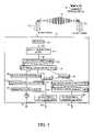
- FIG. 3shows an example of a configuration of the connecting equipment of the enclosure 36 in FIG. 1 in which the office-side connection includes the office side radio tower 52 a connected to the central office 26 for transmitting either a DS1 or a DS3 signal over the radio link 52 .
- the enclosure 36may also include connecting equipment for only a DS3 connection or for only a DS1 connection.
- the enclosure 36includes a DS1 radio 134 , which receives DS1 level signals from the radio tower 52 b .
- the DS1 radio 134is connected to a digital distribution point 138 via a DS1 line 52 b .
- the digital distribution point 138is a terminal location used to electrically connect or multiplex digital signal facilities.
- the digital distribution point 138may include cable terminations to establish electrical connections between any two terminated DS1 network elements.
- the digital distribution point 138provides electrical connections between the DS1 radio 134 and a radio side cross-connect 142 .
- the digital distribution point panel 138includes the DDP-1 84-circuit panel from the ADC Corporation.
- the digital distribution point panel 138is connected to a radio/electrical cross-connect panel 143 via DS1 lines 140 .
- the radio/electrical cross-connect panel 143includes a radio side cross connect panel 142 and an electrical cross connect panel 144 .
- the radio side cross-connect 142is cross-connected to the electrical-side cross-connect 144 using well-known cross-connect systems such as a DSX cross-connect panel, a quick-connect punch-down (QCP) panel or a Litespan.TM. system from DSC.
- the electrical-side cross-connect panel 144may be connected to various types of equipment.
- a second digital distribution point 146may connect the DS1 level lines to an optical/electrical converter 148 .
- the optical/electrical converter 148converts the DS1 signals to a signal in SONET format for transmission on a fiber-optic cable.
- the fiber-optic cablemay be connected to a fiber-optic cross-connect panel 150 for distribution to other distribution systems connected via the fiber-optic outside plan 70 .
- the electrical side cross-connect panel 144may also be connected to the multiplexer 1 / 0 152 for multiplexing a DS1 level line to several DS0 level lines.
- the DS0 level linesare connected to a DS0 electrical cable protection 153 , which is connected to the DS0 lines on the copper cable outside plant 124 .
- the multiplexer 1 / 0 152 in a preferred embodimentis the Litespan.TM. 2000 system from DSC.
- the Litespan.TM. 2000 systemis preferred because it can hand off DS1 lines and DS0 lines and provide multiplexing cross-connect functions and signal conversion for fiber-optic cable.
- the electrical cross-connect panel 144may also be connected to a repeater 154 .
- the repeater 154includes signal amplifiers for boosting a signal that may be part of a connection traversing a long distance.
- the repeater 154may be connected to a second cross-connect system 156 that includes a first cross-connect panel 157 and a second cross-connect panel 158 .
- the second cross-connect panel 158is connected to DS1 lines that comprise the copper outside plant 54 from the subscribers side of the enclosure 100 which is protected by a DS1 electrical cable protection 160 .
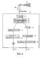
- FIG. 4shows enclosure 36 having an office-side connection to a DS3 radio link 52 .
- the connecting equipment for distributing signals received at a DS3 level in enclosure 36includes a DS3 radio 164 which receives DS3 level signals from the radio tower 52 b .
- the DS3 radio 164is connected to a DSX-3 cross-connect system 168 via DS3 lines 166 .
- the DSX-3 cross-connect systemincludes a first DSX-3 panel 169 and a second DSX-3 cross-connect panel 170 .
- the DSX-3 cross-connect system 168may be implemented in a preferred embodiment using a DSX cross-connect system from the ADC Corporation.
- the DSX cross-connect system 168may be connected to a fiber multiplexer 172 .
- the fiber multiplexer 172provides signal conversion and multiplexing functions for connecting an electrical DS3 line to a fiber-optic line.
- the fiber multiplexer 172may then be connected to a fiber-optic cross-connect panel 174 for distributing fiber-optic signals over the fiber-optic plant 70 .
- the fiber multiplexer 172 and the fiber-optic cross-connect panel 174may be implemented using an FLM 150 from Fujitsu and an LGX distribution frame from Lucent Technologies.
- the DSX cross-connect panel 168may also be connected to a multiplexer 3 / 1 176 .
- the multiplexer 3 / 1 176distributes the DS3 level signals as DS1 level signals.
- the DS1 signalsmay then be processed at a DS1 processing connecting equipment, which may include any of the DS 1 processing equipment in FIG. 3 starting from the digital distribution point 138 as discussed above.
- the multiplexer 3 / 1 176 and any other element that performs multiplexing functions described hereinalso performs de-multiplexing functions for signals that travel from the office-side to the subscriber-side and multiplexing functions for signals that travel from the subscriber-side to the office-side.
- FIG. 5shows a block diagram of the third hut 40 in FIG. 1 , which is connected on the office-side to the first hut 36 via the optical link 70 .
- the third hut 40includes distribution equipment for distributing telecommunications service over radio links 56 , 58 , 60 .
- the third hut 40includes a fiber optic cross-connect panel 182 , an optical/electrical converter 184 , a m/n multiplexer 186 , a DSX cross-connect 188 and DSn radios 192 , 194 , 196 .
- the optical link 70 that connects the third hut 40 in FIG. 4 to the central officeis an OC-1 optical link.
- the connecting equipment in the hut 40multiplexes the DS3 to DS1 links carried by the DS1 radios 192 , 194 , 196 .
- One of ordinary skill in the artwill understand that other signal levels may be processed by the connecting equipment in the hut 40 .
- the fiber optic cross connect panel 182is connected to the office side optical link 70 and provides a cross-connect function for the fiber optic link 70 .
- the fiber optic cross connect panel 182includes the LGX distribution system from Lucent Technologies.
- the fiber optic cross connect panel 182connects to the optical/electrical converter 184 which converts the optical OC-1 signal to an electrical signal.
- the DS3 signalis multiplexed to DS1 signals by the 3/1 multiplexer 186 .
- the DS1 linesare connected to the DSX cross connect panel 188 for distribution to the DS1 radios 192 , 194 , 196 that connect to the subscribers.
- FIG. 6shows the cabinet 46 in the local distribution system 8 .
- the cabinet 46includes a digital interface unit 206 connected to a radio interface unit 200 .
- the radio interface unit 200communicates DS1 level signals over the radio antenna 62 .
- the digital interface unit 206connects DS1 lines to a digital signal cross connect 208 .
- the digital signal cross connect 208connects to a wide band protection unit 210 , which provides electrical protection for the higher frequency DS1 lines.
- the wide band protection unit 210connects the DS1 lines to a digital loop carrier 212 .
- the wide band protection unit 210may include gas beam protection devices, carbon block devices, and solid state devices.
- the digital loop carrier 212is known in the art and, in a preferred embodiment, may be implemented using a Litespan system from the DSC Corporation.
- the digital loop carrier unit 212is connected by plain old telephone system (POTS) lines, or DS0 lines to a narrow band protection unit 214 which provides electrical protection to the lower frequency DS0 lines.
- POTSplain old telephone system
- the narrow band protection unit 214may include gas beam protection devices, carbon block devices, and solid state devices.
- the DS0 linesare connected to the subscriber area interface 218 via a splice cabinet 216 .
- the cabinet 46includes an AC power input 220 connected to an AC line 222 .
- the AC power input 220is connected to a rectifier 224 which converts the AC to DC power used by the electronic equipment in the cabinet 46 .
- the rectifier 224includes a 48 VDC output to a fuse alarm power unit 226 on the digital loop carrier unit 212 .
- the fuse alarm power unit 226is connected to a fan/thermostat 228 used for maintaining the temperature in the cabinet 46 sufficiently cool to permit the electronic equipment to run.
- the cabinet 46may include a battery backup 250 to maintain service when the power fails.
- the cabinet 46 in FIG. 6may be advantageously used to set up a temporary telecommunications link such as the temporary radio link 50 a in FIG. 1 while permanent optical or copper plants are being deployed.
- the cabinet 46may be used for a temporary radio link by using a removable radio frequency unit 200 .
- the radio frequency unit 200may be provided on a pallet, skid or pole with the antenna 60 a while the radio link is operational.
- the digital interface unit 206 , the radio frequency unit 200 and antenna 60 amay then be removed and replaced with a fiber optic cross connect or a digital distribution point when a fiber optic or copper plant is available.
- the radio frequency unit 200 and the digital interface unit 206may be provided as one component on a shelf in the cabinet 46 . The radio may then be removed from the shelf when the fiber or copper plants are available and replaced with the appropriate components.
- a method for installing telecommunications servicemay be implemented for either temporary use of the radio while copper or fiber plants are being deployed.
- the temporary radio link 50permits the telephone service provider to respond quickly to requests for service.
- a user in the service area 12may be the first user in the new service area 12 to require service.
- the service providermay perform a temporary installation such as the one shown in Table 1.
- a next generation digital loop carrier systemhaving: A first digital signal cross-connect (DSX) panel A second DSX panel A protection device Connect a cable between the user location in the service area and the second DSX panel Connect a first temporary radio to the second hut Connect a second temporary radio having a third DSX panel and a protection device to the cabinet with cable Configure the first DSX panel, the second DSX panel, the third DSX panel and the radio link to provide a connection between the user location and the central office.
- DSXdigital signal cross-connect
- a protection deviceConnect a cable between the user location in the service area and the second DSX panel Connect a first temporary radio to the second hut Connect a second temporary radio having a third DSX panel and a protection device to the cabinet with cable Configure the first DSX panel, the second DSX panel, the third DSX panel and the radio link to provide a connection between the user location and the central office.
- the method of Table 1may be augmented during the expansion of the number of users in the new service area by configuring new users at the DSX panels and at the radio link.
- a hard link 195shown in FIG. 1 connecting the cabinet 28 to the cabinet 32 , which may be an optical connection, may be installed to replace the radio link.
- the first and second temporary radiosmay be removed and re-used for another temporary link.
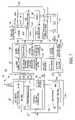
- FIG. 7shows an alternative embodiment for a telecommunications network 300 wherein a central office 302 and a network operations center 304 are communicatively connected to a radio cabinet 306 with a cable distribution cabinet 308 .
- the radio cabinet 306is used to house radio equipment for a radio link 301 with the central office 302 and the cable distribution cabinet 308 is used to house cable distribution equipment for connecting to a plurality of subscribers 370 .
- the telecommunications network 300 in FIG. 7includes a diagnostic system (described below) for communicating alarms to the network operations center 304 in an efficient manner and for providing system testing and alarm diagnostics.
- the radio cabinet 306 and the cable distribution cabinet 308may be co-located, or they may be sufficiently remote from each other to require repeaters.
- the central office 302includes a radio 310 , which is connected to switching equipment (not shown) for communicating with the PSTN (see FIG. 1 ).
- the radio 310uses the radio link 301 to communicate with the radio cabinet 306 which includes signal distribution equipment such as a subscriber side radio 346 , a digital distribution point 344 , a radio quick cross-connect panel 342 and a DS1 protection device 340 .
- the digital distribution point 344 , the radio quick cross-connect panel 342 and the DS1 protection device 340operate similar to corresponding components described above.
- the radio quick cross-connect panel 342 and the digital distribution point 344are optional and are provided for the flexibility of extending to other cable distribution cabinets.
- the radio cabinet 306includes an AC/DC conversion and load distribution panel 330 , a radio heater 338 , a battery set 332 , a waveguide dehydrator 336 and a battery heater 334 as environmental resources for the radio equipment in the radio cabinet 306 .
- the AC/DC conversion and load distribution panel 330converts the AC power to the cabinet into a DC voltage source, provides battery charging functions and load distribution within the radio cabinet 306 .
- the batteries 332are used for a DC power backup.
- the battery heater 334 , radio heater 338 and the waveguide dehydrator 336provide environmental control for the designated elements and equipment as is known to one of ordinary skill in the art.
- the cable distribution cabinet 308includes a DS1 protection device 356 , a DSX-1 cross-connect panel 354 , a transmission remote terminal 352 , a DS0 protection device 360 and a splice cabinet 362 .
- the DS1 protection device 356protects the cable distribution equipment in the cabinet 308 from inductive spikes and other destructive noise that may be generated on a DS1 cable 341 between the radio cabinet 306 and the cable distribution cabinet 308 .
- the DSX-1 cross-connect panel 354 and the transmission remote terminal 352distribute the DS1 signal to the DS0 lines to the subscribers as described above with reference to FIG. 3 .
- the DS0 protection device 360protects the distribution equipment from inductive spikes and other destructive noise coming from the DS0 lines 371 that extend to the subscribers 370 .
- the transmission remote terminal 352includes a DSC Corporation Litespan system that distributes DS1 signals to DS0 lines.
- the diagnostic system in the telecommunications network 300 in FIG. 7includes equipment in a central control location for receiving the status of alarms that have been sensed and transmitted from remote locations.
- the central control location in the network 300 in FIG. 7includes the network operations center 304 , which sends diagnostic instructions and receives responses via the central office diagnostic equipment.
- the central office diagnostic equipment(described further below) communicates with diagnostic equipment in the radio cabinet 306 and in the cable distribution cabinet 308 , and any other similarly equipped huts or cabinets in the serving area of the central office.
- the diagnostic equipment in the radio cabinet 306 and in the cable distribution cabinet 308includes alarm sensors and communications modules.
- the alarm sensorssense alarm conditions and communicate the conditions to the communications modules.
- the communications modulesprocess the alarm conditions and report the conditions by communicating the conditions to the central office diagnostic equipment.
- the central office diagnostic equipmentthen communicates alarm and status conditions for the equipment in the service area of the central office to the network operations center 304 .
- the network operations center 304includes a metallic loop test controller 322 , a radio test controller 324 , and a network monitor and analyzer 326 .
- the metallic loop test controller 322initiates and monitors metallic loop testing of the connections to the subscribers 370 connected to the central office 302 .
- the metallic loop testing processis well known to those of ordinary skill in the art and requires no further description.
- the radio testing controller 324controls the communication of the diagnostic commands to the central office 302 and the status information from the cabinet 306 .
- the central office 302 diagnostic equipmentincludes an extended link monitor (ELM) 312 , a modem 314 , a transmission central office terminal 316 , a central testing controller 318 , and alarm sensors 320 .
- the modem 314is connected to the radio testing controller 324 in the network operations controller 304 by a communications line 315 .
- the radio testing controller 324sends diagnostic commands and receives diagnostic information to and from the modem 314 via the communications line 315 .
- the modemsends the diagnostic commands to the extended link monitor 312 for processing and any commands that should be sent to the radio cabinet 306 are communicated over the radio link 301 .
- the central testing controller 318is connected to the metallic loop testing controller 322 in the network operations center 304 .
- the central testing controller 318controls metallic loop testing operations with the subscriber lines in the service area of the central office 302 by interrogating metallic loop test unit 358 b (described below).
- the central testing controller 318may initiate metallic loop testing by sending commands through the transmission central office terminal 316 .
- the transmission central office terminal 316also extracts alarm information from the communications lines in the central office 302 .
- the alarm sensors 320include sensors to communicate network problems such as equipment failures and environmental alarms.
- the alarm sensor 320includes a radio input 311 a , a radio cabinet input 311 b , and a cable cabinet input 311 c .
- the radio input 311 acommunicates alarm information that is generated upon an alarm condition sensed in the radio 310 .
- the radio cabinet input 311 bcommunicates alarm information received from the alarm sensing equipment in the radio cabinet 306 (described further below).
- the cable cabinet input 311 ccommunicates alarm information received from alarm sensing equipment in the cable distribution cabinet 308 (described below).
- the alarm sensors 320are connected to the network monitor and analyzer 326 in the network operations center 304 .
- An operator at the network monitor and analyzer 326may initiate requests for alarm information and receive reports or logs on display screens or printouts. The operator may also initiate metallic loop testing at the network monitor and analyzer 326 and receive reports.
- the radio cabinet 306includes a radio with ELM 346 , which is connected to alarm connections 328 for communicating alarm conditions sensed in the area of the radio cabinet.
- ELM 346receives diagnostic commands from the central office extended link monitor 312 .
- the alarm connections 328are alarm sensing equipment in the radio cabinet 306 which may include sensors that detect open or short conditions, environmental conditions, equipment failures, signal degradation, etc.
- the radio with ELM 346connects to the signal distribution equipment as discussed above.
- the signal distribution equipmentis used to communicate diagnostic information with the cable distribution cabinet 308 .
- the cable distribution cabinet 308includes an alarm sensor 358 a and a metallic loop testing unit 358 b .
- the alarm sensor 358 asenses alarm condition such as open or short conditions, environmental conditions, equipment failures, signal degradation, etc.
- the metallic loop testing unit 358 bmanages the metallic loop testing process at the subscriber side.
- the alarm sensor 358 a and the metallic loop-testing unit 358 bcommunicate diagnostic information via the transmission remote
- the alarm sensors 358 a and the metallic loop testing unit 358 bcommunicate with the radio with ELM 346 in the radio cabinet 306 by carrying the diagnostic information on a channel on the DS1 signal.
- the channelmay be a data (e.g. RS232 channel), a voice channel (e.g. DS0 channel), or it may be a control channel.
- the channelcommunicates the information over the radio link 301 with the central office 302 .
- the advantage of using the diagnostic equipment in the network 300 in FIG. 7is that alarms may be sensed remotely in the service area served by the central office 302 and communicated to the central office 302 which ultimately communicates the diagnostic information to the network operations center 304 .
- the alarm sensor 358 a , the metallic loop testing unit 358 b , and the alarm connections 328 in the radio cabinet 306may each communicate as a subscriber on a channel of the DS1 signal.
- the channelmay be known to the extended link monitor 312 and to the central testing controller 318 to provide the diagnostic information to the network operations center 304 from the extended link monitor system and from the metallic loop testing system.
- the extended link monitor equipmentwhich includes the extended link monitor 312 and the radio with ELM 346 may include the Alcatel MDR 6000 Series radio.
- the metallic loop testing equipmentmay include the Wiltron Loopmate or CO Tollgrade.
- One advantage of the diagnostic system shown in FIG. 7is that problems with the telecommunications system are monitored on an ongoing basis with little user intervention. Reporting and test procedures may be set up to occur automatically or at scheduled times.
Landscapes
- Engineering & Computer Science (AREA)
- Computer Networks & Wireless Communication (AREA)
- Signal Processing (AREA)
- Telephonic Communication Services (AREA)
- Mobile Radio Communication Systems (AREA)
Abstract
Description
| TABLE 1 | |||
| Install the cabinet | A next generation digital loop carrier system | ||
| having: | A first digital signal cross-connect (DSX) panel | ||
| A second DSX panel | |||
| A protection device | |||
| Connect a cable between the user location in the service area | ||
| and the second DSX panel | ||
| Connect a first temporary radio to the second hut | ||
| Connect a second temporary radio having a third DSX panel and a | ||
| protection device to the cabinet with cable | ||
| Configure the first DSX panel, the second DSX panel, the | ||
| third DSX panel and the radio link to provide a connection between | ||
| the user location and the central office. | ||
Claims (6)
Priority Applications (1)
| Application Number | Priority Date | Filing Date | Title |
|---|---|---|---|
| US10/822,439US7590052B2 (en) | 1998-09-11 | 2004-04-12 | System and method for providing telecommunications service using a wireless link |
Applications Claiming Priority (3)
| Application Number | Priority Date | Filing Date | Title |
|---|---|---|---|
| US09/151,882US6415150B1 (en) | 1998-09-11 | 1998-09-11 | System and method for providing telecommunications service using a wireless link |
| US10/036,971US6788942B2 (en) | 1998-09-11 | 2001-12-20 | System and method for providing telecommunications service using a wireless link |
| US10/822,439US7590052B2 (en) | 1998-09-11 | 2004-04-12 | System and method for providing telecommunications service using a wireless link |
Related Parent Applications (1)
| Application Number | Title | Priority Date | Filing Date |
|---|---|---|---|
| US10/036,971ContinuationUS6788942B2 (en) | 1998-09-11 | 2001-12-20 | System and method for providing telecommunications service using a wireless link |
Publications (2)
| Publication Number | Publication Date |
|---|---|
| US20040264446A1 US20040264446A1 (en) | 2004-12-30 |
| US7590052B2true US7590052B2 (en) | 2009-09-15 |
Family
ID=22540642
Family Applications (3)
| Application Number | Title | Priority Date | Filing Date |
|---|---|---|---|
| US09/151,882Expired - Fee RelatedUS6415150B1 (en) | 1998-09-11 | 1998-09-11 | System and method for providing telecommunications service using a wireless link |
| US10/036,971Expired - Fee RelatedUS6788942B2 (en) | 1998-09-11 | 2001-12-20 | System and method for providing telecommunications service using a wireless link |
| US10/822,439Expired - Fee RelatedUS7590052B2 (en) | 1998-09-11 | 2004-04-12 | System and method for providing telecommunications service using a wireless link |
Family Applications Before (2)
| Application Number | Title | Priority Date | Filing Date |
|---|---|---|---|
| US09/151,882Expired - Fee RelatedUS6415150B1 (en) | 1998-09-11 | 1998-09-11 | System and method for providing telecommunications service using a wireless link |
| US10/036,971Expired - Fee RelatedUS6788942B2 (en) | 1998-09-11 | 2001-12-20 | System and method for providing telecommunications service using a wireless link |
Country Status (1)
| Country | Link |
|---|---|
| US (3) | US6415150B1 (en) |
Families Citing this family (24)
| Publication number | Priority date | Publication date | Assignee | Title |
|---|---|---|---|---|
| US6415150B1 (en)* | 1998-09-11 | 2002-07-02 | Ameritech Corporation | System and method for providing telecommunications service using a wireless link |
| US7155217B1 (en)* | 2000-07-26 | 2006-12-26 | Lucent Technologies Inc. | Method and apparatus for managing adjunct access and leased facilities |
| US7546122B1 (en)* | 2001-05-03 | 2009-06-09 | Dark Air, Inc. | Method and apparatus for providing a wireless interoffice facility |
| US6879679B1 (en) | 2001-05-22 | 2005-04-12 | Cisco Technology, Inc. | Analysis method for provisioning subscribers in a next generation telecommunications network |
| US7352853B1 (en)* | 2001-05-22 | 2008-04-01 | Cisco Technology, Inc. | Automation of customer premises equipment provisioning in a telecommunications network |
| US7127175B2 (en)* | 2001-06-08 | 2006-10-24 | Nextg Networks | Method and apparatus for multiplexing in a wireless communication infrastructure |
| US6826163B2 (en)* | 2001-06-08 | 2004-11-30 | Nextg Networks | Method and apparatus for multiplexing in a wireless communication infrastructure |
| US20020191565A1 (en)* | 2001-06-08 | 2002-12-19 | Sanjay Mani | Methods and systems employing receive diversity in distributed cellular antenna applications |
| US6826164B2 (en)* | 2001-06-08 | 2004-11-30 | Nextg Networks | Method and apparatus for multiplexing in a wireless communication infrastructure |
| US7162156B2 (en)* | 2001-08-13 | 2007-01-09 | L-3 Communication Corporation | Bi-directional single fiber optic link for data and radio frequency transmissions |
| US6907246B2 (en)* | 2001-11-20 | 2005-06-14 | Navini Networks, Inc. | Method and system for reducing wireless multi-cell interferences through segregated channel assignments and segregated antenna beams |
| US20040198453A1 (en)* | 2002-09-20 | 2004-10-07 | David Cutrer | Distributed wireless network employing utility poles and optical signal distribution |
| US7053501B1 (en)* | 2002-11-04 | 2006-05-30 | Cisco Technology, Inc. | Multi-pair aggregate power distribution |
| US7127220B2 (en)* | 2002-12-23 | 2006-10-24 | Spectrasite Communications Inc | Apparatus and method to monitor and control power |
| KR20040064853A (en)* | 2003-01-10 | 2004-07-21 | 유티스타콤코리아 유한회사 | Distributed multi-drop base station and repeating unit using extension analog optical transmission in mobile communication system |
| US7840989B2 (en)* | 2003-06-16 | 2010-11-23 | Bertonis James G | Apparatus and method for extending a cable modem data service over wireless links |
| FR2875083B1 (en)* | 2004-09-03 | 2006-12-15 | Cit Alcatel | MODULAR DIAGNOSTIC DEVICE BASED ON EVOLUTIVE KNOWLEDGE FOR A COMMUNICATIONS NETWORK |
| JP2007174003A (en)* | 2005-12-20 | 2007-07-05 | Hitachi Ltd | Proxy response terminal and system |
| US7949344B1 (en) | 2006-02-13 | 2011-05-24 | Wireless Strategies, Inc. | Uncoordinated microwave paths in coordinated frequency bands |
| US20070288612A1 (en)* | 2006-06-12 | 2007-12-13 | Electronic Data Systems Corporation | Assembly, and associated method, for provisioning computer device with computer data |
| US7839816B2 (en) | 2006-06-12 | 2010-11-23 | Hewlett-Packard Development Company, L.P. | Assembly, and associated methodology, for provisioning computer device with operating software |
| US8965150B2 (en) | 2008-05-29 | 2015-02-24 | Commscope, Inc. Of North Carolina | Optical switch assembly for detecting movement |
| US8368534B2 (en)* | 2008-05-29 | 2013-02-05 | Commscope Inc. Of North Carolina | Optical fiber systems and methods for monitoring remote door access |
| US8086280B2 (en)* | 2008-06-16 | 2011-12-27 | Rivada Networks Llc | Explosion proof communications relay and communications system |
Citations (51)
| Publication number | Priority date | Publication date | Assignee | Title |
|---|---|---|---|---|
| US3778555A (en) | 1971-07-19 | 1973-12-11 | Digital Telephone Systems Inc | Telephone subscriber line system intra call apparatus and method |
| US3823401A (en) | 1972-10-04 | 1974-07-09 | Data Transmission Co | Synchronous data transmission network |
| US3824597A (en) | 1970-11-09 | 1974-07-16 | Data Transmission Co | Data transmission network |
| US4393491A (en) | 1980-11-05 | 1983-07-12 | Anaconda-Ericsson | Automatic self-test system for a digital multiplexed telecommunication system |
| US4528656A (en) | 1982-07-02 | 1985-07-09 | Harris Corporation | Radio communication system using frequency division multiplexing for transmission between a master station and a plurality of remote stations |
| US4625308A (en) | 1982-11-30 | 1986-11-25 | American Satellite Company | All digital IDMA dynamic channel allocated satellite communications system and method |
| US4777633A (en)* | 1987-08-14 | 1988-10-11 | International Mobile Machines Corp. | Base station for wireless digital telephone system |
| US4922517A (en) | 1987-04-08 | 1990-05-01 | Metrofone, Inc. | System for interfacing a standard telephone set with a radio transceiver |
| US4924496A (en) | 1988-05-12 | 1990-05-08 | Romek Figa D/B/A Abraham & Sons | Automatic incoming telephone call originating number and party display system |
| US4948960A (en)* | 1988-09-20 | 1990-08-14 | The University Of Delaware | Dual mode light emitting diode/detector diode for optical fiber transmission lines |
| US5173896A (en)* | 1990-11-30 | 1992-12-22 | Bell Atlantic Network Services, Inc. | T-carrier network simulator |
| US5274694A (en)* | 1989-12-22 | 1993-12-28 | Siemens Aktiengesellschaft | Radio communication network based on digital local exchanges |
| US5463671A (en) | 1992-11-16 | 1995-10-31 | Csir | Telecommunications network having a distributed network of decentralized local stations |
| US5467385A (en) | 1994-01-27 | 1995-11-14 | Reuben; Douglas S. | Calling number display and recording system |
| US5544227A (en) | 1993-08-31 | 1996-08-06 | Bellsouth Corporation | Radiotelephone communications system with direct access to interoffice telephone trunk circuits and interface therefor |
| US5546447A (en) | 1994-06-29 | 1996-08-13 | Intel Corporation | Displaying caller identification information in a computer system |
| US5566235A (en) | 1995-10-05 | 1996-10-15 | Bell Atlantic Network Services, Inc. | Customer controlled service mediation management |
| US5572576A (en) | 1992-03-31 | 1996-11-05 | Klausner Patent Technologies | Telephone answering device linking displayed data with recorded audio message |
| US5594784A (en) | 1993-04-27 | 1997-01-14 | Southwestern Bell Technology Resources, Inc. | Apparatus and method for transparent telephony utilizing speech-based signaling for initiating and handling calls |
| US5623537A (en) | 1994-12-29 | 1997-04-22 | Lucent Technologies Inc. | Telephone message center |
| US5651054A (en) | 1995-04-13 | 1997-07-22 | Active Voice Corporation | Method and apparatus for monitoring a message in a voice mail system |
| US5664009A (en) | 1992-03-13 | 1997-09-02 | Allnet Communication Services, Inc. | Voice mail notification system |
| US5692038A (en) | 1992-08-26 | 1997-11-25 | Bellsouth Corporation | Method for identifying the source of a telephonic communication |
| US5706334A (en) | 1994-08-18 | 1998-01-06 | Lucent Technologies Inc. | Apparatus for providing a graphical control interface |
| US5751789A (en) | 1995-11-13 | 1998-05-12 | Bell Atlantic Network Services, Inc. | SNID with wireless backup |
| US5884148A (en) | 1996-07-08 | 1999-03-16 | Omnipoint Corporation | Wireless local loop system and method |
| US5963864A (en) | 1996-05-31 | 1999-10-05 | Bellsouth Intellectual Property Management Corporation | Method and system for automatically connecting telephone calls to multiple devices having different directory numbers |
| US6006069A (en)* | 1994-11-28 | 1999-12-21 | Bosch Telecom Gmbh | Point-to-multipoint communications system |
| US6014546A (en) | 1996-04-19 | 2000-01-11 | Lgc Wireless, Inc. | Method and system providing RF distribution for fixed wireless local loop service |
| US6047160A (en)* | 1996-08-29 | 2000-04-04 | Ericsson Inc. | Transportable base station for a trunked radio communication system |
| US6112056A (en)* | 1995-06-07 | 2000-08-29 | Cisco Systems, Inc. | Low power, short range point-to-multipoint communications system |
| US6115603A (en) | 1997-07-18 | 2000-09-05 | Nortel Networks Corporation | Class in-band service delivery over fixed wireless access communication systems |
| US6141356A (en)* | 1997-11-10 | 2000-10-31 | Ameritech Corporation | System and method for distributing voice and data information over wireless and wireline networks |
| US6181710B1 (en)* | 1997-06-11 | 2001-01-30 | Alcatel Usa Sourcing, L.P. | Handling of telecommunications signals passed between elements of a telecommunications network |
| US6212397B1 (en)* | 1996-12-23 | 2001-04-03 | Texas Instruments Incorporated | Method and system for controlling remote multipoint stations |
| US6215867B1 (en)* | 1997-06-20 | 2001-04-10 | At&T Corp. | Telecommunications network architecture with rapid restoration |
| US6223054B1 (en)* | 1997-02-26 | 2001-04-24 | Lightsource Telecom, Llc | Wireless local loop system utilizing independent central offices located in new residential and commercial developments |
| US20010006517A1 (en)* | 1997-10-31 | 2001-07-05 | Jie Lin | Asymmetric data access scheme |
| US6278700B1 (en) | 1995-10-31 | 2001-08-21 | Telefonaktiebolaget Lm Ericsson (Publ) | Arrangement and method relating to telecommunications networks |
| US6304762B1 (en)* | 1996-12-23 | 2001-10-16 | Texas Instruments Incorporated | Point to multipoint communication system with subsectored upstream antennas |
| US20010055286A1 (en)* | 1998-03-31 | 2001-12-27 | Jie Lin | Asymmetric internet access over fixed wireless access |
| US6377800B1 (en)* | 1998-09-08 | 2002-04-23 | Samsung Electronics Co., Ltd. | Resource assignment method according to the data transmission types in wireless local loop system |
| US6415150B1 (en)* | 1998-09-11 | 2002-07-02 | Ameritech Corporation | System and method for providing telecommunications service using a wireless link |
| US20020181503A1 (en)* | 2001-04-06 | 2002-12-05 | Montgomery Charles D. | Dynamic communication channel allocation method and system |
| US20020196759A1 (en)* | 1997-12-10 | 2002-12-26 | Yuhan Albert H. | Monitoring in communication system with wireless trunk |
| US20030172145A1 (en)* | 2002-03-11 | 2003-09-11 | Nguyen John V. | System and method for designing, developing and implementing internet service provider architectures |
| US6665546B2 (en)* | 2001-05-02 | 2003-12-16 | Trex Enterprises Corporation | High speed, point-to-point, millimeter wave dated communication system |
| US6775562B1 (en)* | 2000-04-17 | 2004-08-10 | Sbc Properties, Lp | Remote battery replacement notification system and method |
| US6977916B1 (en)* | 1998-04-29 | 2005-12-20 | Nokia Corporation | Method of connecting network elements to a radio system, and radio system |
| US20060025158A1 (en)* | 1996-09-09 | 2006-02-02 | Leblanc Frederick W | Locating a mobile station and applications therefor |
| US20060179460A1 (en)* | 2000-07-19 | 2006-08-10 | Verizon Corporate Services Group Inc. | System and method for providing a graphical representation of a frame inside a central office of a telecommunications system |
Family Cites Families (3)
| Publication number | Priority date | Publication date | Assignee | Title |
|---|---|---|---|---|
| US5040170A (en)* | 1988-12-09 | 1991-08-13 | Transwitch Corporation | System for cross-connecting high speed digital signals |
| US6198720B1 (en)* | 1996-12-26 | 2001-03-06 | Alcatel Usa Sourcing, L.P. | Distributed digital cross-connect system and method |
| US5991312A (en)* | 1997-11-03 | 1999-11-23 | Carrier Access Corporation | Telecommunications multiplexer |
- 1998
- 1998-09-11USUS09/151,882patent/US6415150B1/ennot_activeExpired - Fee Related
- 2001
- 2001-12-20USUS10/036,971patent/US6788942B2/ennot_activeExpired - Fee Related
- 2004
- 2004-04-12USUS10/822,439patent/US7590052B2/ennot_activeExpired - Fee Related
Patent Citations (57)
| Publication number | Priority date | Publication date | Assignee | Title |
|---|---|---|---|---|
| US3824597A (en) | 1970-11-09 | 1974-07-16 | Data Transmission Co | Data transmission network |
| US3778555A (en) | 1971-07-19 | 1973-12-11 | Digital Telephone Systems Inc | Telephone subscriber line system intra call apparatus and method |
| US3823401A (en) | 1972-10-04 | 1974-07-09 | Data Transmission Co | Synchronous data transmission network |
| US4393491A (en) | 1980-11-05 | 1983-07-12 | Anaconda-Ericsson | Automatic self-test system for a digital multiplexed telecommunication system |
| US4528656A (en) | 1982-07-02 | 1985-07-09 | Harris Corporation | Radio communication system using frequency division multiplexing for transmission between a master station and a plurality of remote stations |
| US4625308A (en) | 1982-11-30 | 1986-11-25 | American Satellite Company | All digital IDMA dynamic channel allocated satellite communications system and method |
| US4922517A (en) | 1987-04-08 | 1990-05-01 | Metrofone, Inc. | System for interfacing a standard telephone set with a radio transceiver |
| US4777633A (en)* | 1987-08-14 | 1988-10-11 | International Mobile Machines Corp. | Base station for wireless digital telephone system |
| US4924496A (en) | 1988-05-12 | 1990-05-08 | Romek Figa D/B/A Abraham & Sons | Automatic incoming telephone call originating number and party display system |
| US4948960A (en)* | 1988-09-20 | 1990-08-14 | The University Of Delaware | Dual mode light emitting diode/detector diode for optical fiber transmission lines |
| US5274694A (en)* | 1989-12-22 | 1993-12-28 | Siemens Aktiengesellschaft | Radio communication network based on digital local exchanges |
| US5173896A (en)* | 1990-11-30 | 1992-12-22 | Bell Atlantic Network Services, Inc. | T-carrier network simulator |
| US5664009A (en) | 1992-03-13 | 1997-09-02 | Allnet Communication Services, Inc. | Voice mail notification system |
| US5572576A (en) | 1992-03-31 | 1996-11-05 | Klausner Patent Technologies | Telephone answering device linking displayed data with recorded audio message |
| US5692038A (en) | 1992-08-26 | 1997-11-25 | Bellsouth Corporation | Method for identifying the source of a telephonic communication |
| US5463671A (en) | 1992-11-16 | 1995-10-31 | Csir | Telecommunications network having a distributed network of decentralized local stations |
| US5594784A (en) | 1993-04-27 | 1997-01-14 | Southwestern Bell Technology Resources, Inc. | Apparatus and method for transparent telephony utilizing speech-based signaling for initiating and handling calls |
| US5544227A (en) | 1993-08-31 | 1996-08-06 | Bellsouth Corporation | Radiotelephone communications system with direct access to interoffice telephone trunk circuits and interface therefor |
| US5467385A (en) | 1994-01-27 | 1995-11-14 | Reuben; Douglas S. | Calling number display and recording system |
| US5546447A (en) | 1994-06-29 | 1996-08-13 | Intel Corporation | Displaying caller identification information in a computer system |
| US5706334A (en) | 1994-08-18 | 1998-01-06 | Lucent Technologies Inc. | Apparatus for providing a graphical control interface |
| US6101174A (en)* | 1994-11-28 | 2000-08-08 | Texas Instruments Incorporated | Low power, short range point-to-multipoint communications systems |
| US6006069A (en)* | 1994-11-28 | 1999-12-21 | Bosch Telecom Gmbh | Point-to-multipoint communications system |
| US5623537A (en) | 1994-12-29 | 1997-04-22 | Lucent Technologies Inc. | Telephone message center |
| US5651054A (en) | 1995-04-13 | 1997-07-22 | Active Voice Corporation | Method and apparatus for monitoring a message in a voice mail system |
| US6553239B1 (en)* | 1995-06-07 | 2003-04-22 | Cisco Technology, Inc. | Low power, short range point-to-multipoint communications system |
| US6112056A (en)* | 1995-06-07 | 2000-08-29 | Cisco Systems, Inc. | Low power, short range point-to-multipoint communications system |
| US5566235A (en) | 1995-10-05 | 1996-10-15 | Bell Atlantic Network Services, Inc. | Customer controlled service mediation management |
| US6278700B1 (en) | 1995-10-31 | 2001-08-21 | Telefonaktiebolaget Lm Ericsson (Publ) | Arrangement and method relating to telecommunications networks |
| US5751789A (en) | 1995-11-13 | 1998-05-12 | Bell Atlantic Network Services, Inc. | SNID with wireless backup |
| US6014546A (en) | 1996-04-19 | 2000-01-11 | Lgc Wireless, Inc. | Method and system providing RF distribution for fixed wireless local loop service |
| US5963864A (en) | 1996-05-31 | 1999-10-05 | Bellsouth Intellectual Property Management Corporation | Method and system for automatically connecting telephone calls to multiple devices having different directory numbers |
| US5884148A (en) | 1996-07-08 | 1999-03-16 | Omnipoint Corporation | Wireless local loop system and method |
| US6047160A (en)* | 1996-08-29 | 2000-04-04 | Ericsson Inc. | Transportable base station for a trunked radio communication system |
| US20060025158A1 (en)* | 1996-09-09 | 2006-02-02 | Leblanc Frederick W | Locating a mobile station and applications therefor |
| US6212397B1 (en)* | 1996-12-23 | 2001-04-03 | Texas Instruments Incorporated | Method and system for controlling remote multipoint stations |
| US6304762B1 (en)* | 1996-12-23 | 2001-10-16 | Texas Instruments Incorporated | Point to multipoint communication system with subsectored upstream antennas |
| US6223054B1 (en)* | 1997-02-26 | 2001-04-24 | Lightsource Telecom, Llc | Wireless local loop system utilizing independent central offices located in new residential and commercial developments |
| US6181710B1 (en)* | 1997-06-11 | 2001-01-30 | Alcatel Usa Sourcing, L.P. | Handling of telecommunications signals passed between elements of a telecommunications network |
| US6215867B1 (en)* | 1997-06-20 | 2001-04-10 | At&T Corp. | Telecommunications network architecture with rapid restoration |
| US6115603A (en) | 1997-07-18 | 2000-09-05 | Nortel Networks Corporation | Class in-band service delivery over fixed wireless access communication systems |
| US20010006517A1 (en)* | 1997-10-31 | 2001-07-05 | Jie Lin | Asymmetric data access scheme |
| US20050271080A1 (en)* | 1997-11-10 | 2005-12-08 | Sbc Properties, L.P. | System and method for distributing voice and data information over wireless and wireline networks |
| US6141356A (en)* | 1997-11-10 | 2000-10-31 | Ameritech Corporation | System and method for distributing voice and data information over wireless and wireline networks |
| US20020196759A1 (en)* | 1997-12-10 | 2002-12-26 | Yuhan Albert H. | Monitoring in communication system with wireless trunk |
| US6400701B2 (en)* | 1998-03-31 | 2002-06-04 | Nortel Networks Limited | Asymmetric internet access over fixed wireless access |
| US20010055286A1 (en)* | 1998-03-31 | 2001-12-27 | Jie Lin | Asymmetric internet access over fixed wireless access |
| US6977916B1 (en)* | 1998-04-29 | 2005-12-20 | Nokia Corporation | Method of connecting network elements to a radio system, and radio system |
| US6377800B1 (en)* | 1998-09-08 | 2002-04-23 | Samsung Electronics Co., Ltd. | Resource assignment method according to the data transmission types in wireless local loop system |
| US6415150B1 (en)* | 1998-09-11 | 2002-07-02 | Ameritech Corporation | System and method for providing telecommunications service using a wireless link |
| US6788942B2 (en)* | 1998-09-11 | 2004-09-07 | Sbc Properties, L.P. | System and method for providing telecommunications service using a wireless link |
| US20040264446A1 (en)* | 1998-09-11 | 2004-12-30 | Sbc Properties, L.P. | System and method for providing telecommunications service using a wireless link |
| US6775562B1 (en)* | 2000-04-17 | 2004-08-10 | Sbc Properties, Lp | Remote battery replacement notification system and method |
| US20060179460A1 (en)* | 2000-07-19 | 2006-08-10 | Verizon Corporate Services Group Inc. | System and method for providing a graphical representation of a frame inside a central office of a telecommunications system |
| US20020181503A1 (en)* | 2001-04-06 | 2002-12-05 | Montgomery Charles D. | Dynamic communication channel allocation method and system |
| US6665546B2 (en)* | 2001-05-02 | 2003-12-16 | Trex Enterprises Corporation | High speed, point-to-point, millimeter wave dated communication system |
| US20030172145A1 (en)* | 2002-03-11 | 2003-09-11 | Nguyen John V. | System and method for designing, developing and implementing internet service provider architectures |
Also Published As
| Publication number | Publication date |
|---|---|
| US20040264446A1 (en) | 2004-12-30 |
| US20020155836A1 (en) | 2002-10-24 |
| US6415150B1 (en) | 2002-07-02 |
| US6788942B2 (en) | 2004-09-07 |
Similar Documents
| Publication | Publication Date | Title |
|---|---|---|
| US7590052B2 (en) | System and method for providing telecommunications service using a wireless link | |
| US5854824A (en) | Connectivity scanner | |
| AU652270B2 (en) | Optical serial bus interface | |
| US5777769A (en) | Device and method for providing high speed data transfer through a drop line of a power line carrier communication system | |
| US5729370A (en) | Method for upgrading a communications network | |
| GB2331666A (en) | Subscriber Terminal for a Wireless Telecommunications System | |
| US5592475A (en) | Distributed digital loop system with trunk unit interface | |
| US6181710B1 (en) | Handling of telecommunications signals passed between elements of a telecommunications network | |
| EP1753217A2 (en) | RF Extender co-located with a remote DSL system | |
| US6396611B1 (en) | Modular optical network units and mounting arrangement | |
| Toms | An integrated network using fiber optics (INFO) for the distribution of video, data and telephony in rural areas | |
| US20160353183A1 (en) | Communications interface | |
| Worley | The Datran System | |
| Rowbotham et al. | Plans for the Bishops Stortford (UK) fibre to the home trials | |
| EP0333340A1 (en) | Multiplexer | |
| KR100938956B1 (en) | Method for connecting a plurality of computer terminals to a broadband cable | |
| JP3377921B2 (en) | Optical coaxial hybrid CATV system | |
| Dalarsson | A recommendation for centralized powering of local network elements | |
| WO1998037711A2 (en) | A receiver unit for a central terminal of a wireless telecommunications system | |
| Berlin et al. | Development of the urban and rural transmission networks in Russia | |
| Romans et al. | A fiber‐optic system for deployment of pots and CATV services in the FRG | |
| Grabenhorst et al. | A FITL system for deployment of optical fibers in germany (OPAL 93)-a basis for evolution of access networks | |
| Reed | Economic comparisons of alternative fiber‐based local access architectures using ATM components | |
| Jankovic et al. | Access network target architecture | |
| GB2331667A (en) | Compensation for signal loss between antenna processing unit and modem unit of a subscriber terminal |
Legal Events
| Date | Code | Title | Description |
|---|---|---|---|
| FEPP | Fee payment procedure | Free format text:PAYOR NUMBER ASSIGNED (ORIGINAL EVENT CODE: ASPN); ENTITY STATUS OF PATENT OWNER: LARGE ENTITY | |
| AS | Assignment | Owner name:AT&T INTELLECTUAL PROPERTY 1, L.P., NEVADA Free format text:CHANGE OF NAME;ASSIGNOR:SBC PROPERTIES, L.P.;REEL/FRAME:022457/0815 Effective date:20030610 Owner name:AT&T INTELLECTUAL PROPERTY 1, L.P.,NEVADA Free format text:CHANGE OF NAME;ASSIGNOR:SBC PROPERTIES, L.P.;REEL/FRAME:022457/0815 Effective date:20030610 | |
| STCF | Information on status: patent grant | Free format text:PATENTED CASE | |
| FPAY | Fee payment | Year of fee payment:4 | |
| FPAY | Fee payment | Year of fee payment:8 | |
| AS | Assignment | Owner name:AMERITECH CORPORATION, ILLINOIS Free format text:ASSIGNMENT OF ASSIGNORS INTEREST;ASSIGNORS:OWENS, MICHAEL KEVIN;CARPENTER, DENNIS ALDON;SIGNING DATES FROM 19981103 TO 19981110;REEL/FRAME:046217/0305 | |
| AS | Assignment | Owner name:PROSPER TECHNOLOGY, LLC, DELAWARE Free format text:ASSIGNMENT OF ASSIGNORS INTEREST;ASSIGNOR:AT&T INTELLECTUAL PROPERTY I, L.P.;REEL/FRAME:046556/0096 Effective date:20180628 | |
| AS | Assignment | Owner name:AMERITECH PROPERTIES, INC., NEVADA Free format text:ASSIGNMENT OF ASSIGNORS INTEREST;ASSIGNOR:AMERITECH CORPORATION;REEL/FRAME:046403/0952 Effective date:20020626 Owner name:SBC HOLDINGS PROPERTIES, L.P., NEVADA Free format text:ASSIGNMENT OF ASSIGNORS INTEREST;ASSIGNOR:AMERITECH PROPERTIES, INC.;REEL/FRAME:046404/0195 Effective date:20020626 Owner name:SBC PROPERTIES, L.P., NEVADA Free format text:ASSIGNMENT OF ASSIGNORS INTEREST;ASSIGNOR:SBC HOLDINGS PROPERTIES, L.P.;REEL/FRAME:046404/0495 Effective date:20020626 Owner name:AT&T KNOWLEDGE VENTURES, L.P., NEVADA Free format text:CHANGE OF NAME;ASSIGNOR:SBC KNOWLEDGE VENTURES, L.P.;REEL/FRAME:046595/0394 Effective date:20060224 Owner name:AT&T INTELLECTUAL PROPERTY I, L.P., GEORGIA Free format text:CHANGE OF NAME;ASSIGNOR:AT&T KNOWLEDGE VENTURES, L.P.;REEL/FRAME:046595/0617 Effective date:20071001 | |
| AS | Assignment | Owner name:LYFT, INC., CALIFORNIA Free format text:ASSIGNMENT OF ASSIGNORS INTEREST;ASSIGNOR:PROSPER TECHNOLOGY, LLC;REEL/FRAME:048097/0353 Effective date:20190118 | |
| AS | Assignment | Owner name:SBC KNOWLEDGE VENTURES, L.P., NEVADA Free format text:CORRECTIVE ASSIGNMENT TO CORRECT THE NAME OF ASSIGNEE PREVIOUSLY RECORDED ON REEL 022457 FRAME 0815. ASSIGNOR(S) HEREBY CONFIRMS THE NAME OF ASSIGNEE IS SBC KNOWLEDGE VENTURES, L.P.;ASSIGNOR:SBC PROPERTIES, L.P.;REEL/FRAME:048419/0507 Effective date:20030610 | |
| FEPP | Fee payment procedure | Free format text:MAINTENANCE FEE REMINDER MAILED (ORIGINAL EVENT CODE: REM.); ENTITY STATUS OF PATENT OWNER: LARGE ENTITY | |
| LAPS | Lapse for failure to pay maintenance fees | Free format text:PATENT EXPIRED FOR FAILURE TO PAY MAINTENANCE FEES (ORIGINAL EVENT CODE: EXP.); ENTITY STATUS OF PATENT OWNER: LARGE ENTITY | |
| STCH | Information on status: patent discontinuation | Free format text:PATENT EXPIRED DUE TO NONPAYMENT OF MAINTENANCE FEES UNDER 37 CFR 1.362 | |
| FP | Lapsed due to failure to pay maintenance fee | Effective date:20210915 |