US7588555B2 - Bi-directional catheter assembly and method therefor - Google Patents
Bi-directional catheter assembly and method thereforDownload PDFInfo
- Publication number
- US7588555B2 US7588555B2US10/670,150US67015003AUS7588555B2US 7588555 B2US7588555 B2US 7588555B2US 67015003 AUS67015003 AUS 67015003AUS 7588555 B2US7588555 B2US 7588555B2
- Authority
- US
- United States
- Prior art keywords
- tubular support
- flexible element
- deflectable
- actuator
- lumen
- Prior art date
- Legal status (The legal status is an assumption and is not a legal conclusion. Google has not performed a legal analysis and makes no representation as to the accuracy of the status listed.)
- Expired - Lifetime, expires
Links
- 238000000034methodMethods0.000titleclaimsdescription28
- 230000007246mechanismEffects0.000claimsdescription20
- 230000000295complement effectEffects0.000claimsdescription9
- 230000006835compressionEffects0.000description7
- 238000007906compressionMethods0.000description7
- 229910001220stainless steelInorganic materials0.000description3
- 239000010935stainless steelSubstances0.000description3
- 210000004204blood vesselAnatomy0.000description2
- 230000008878couplingEffects0.000description2
- 238000010168coupling processMethods0.000description2
- 238000005859coupling reactionMethods0.000description2
- 239000004033plasticSubstances0.000description2
- 229920003023plasticPolymers0.000description2
- 210000005166vasculatureAnatomy0.000description2
- 241000282346Meles melesSpecies0.000description1
- 238000002679ablationMethods0.000description1
- 238000010276constructionMethods0.000description1
- 238000012864cross contaminationMethods0.000description1
- 230000007547defectEffects0.000description1
- 239000012530fluidSubstances0.000description1
- 239000000463materialSubstances0.000description1
- 239000002184metalSubstances0.000description1
- 229910052751metalInorganic materials0.000description1
- 150000002739metalsChemical class0.000description1
- 239000004810polytetrafluoroethyleneSubstances0.000description1
- 229920001343polytetrafluoroethylenePolymers0.000description1
- 230000000472traumatic effectEffects0.000description1
Images


Classifications
- A—HUMAN NECESSITIES
- A61—MEDICAL OR VETERINARY SCIENCE; HYGIENE
- A61M—DEVICES FOR INTRODUCING MEDIA INTO, OR ONTO, THE BODY; DEVICES FOR TRANSDUCING BODY MEDIA OR FOR TAKING MEDIA FROM THE BODY; DEVICES FOR PRODUCING OR ENDING SLEEP OR STUPOR
- A61M25/00—Catheters; Hollow probes
- A61M25/01—Introducing, guiding, advancing, emplacing or holding catheters
- A61M25/0105—Steering means as part of the catheter or advancing means; Markers for positioning
- A61M25/0133—Tip steering devices
- A61M25/0147—Tip steering devices with movable mechanical means, e.g. pull wires
Definitions
- the present inventionrelates generally to a deflectable catheter assembly. More particularly, it pertains to a bi-directional catheter assembly for a deflectable catheter assembly.
- a guidewireinto a desired part of the lumen of a desired vessel or duct, such as a blood vessel.
- a catheter or other tubular devicemay be positioned over the guidewire and used to convey other medical instruments into the desired blood vessel or duct.
- a guiding catheteris used to negotiate the vasculature of a patient.
- a guiding catheteris described in U.S. Pat. No. 4,898,577 to Badger et al.
- the Badger guiding catheterincludes a single elongate shaft that has a deflectable distal portion controllable by a pull wire.
- multiple pull wiresare used to pull on the distal end and cause it to defect in more than one direction.
- U.S. Pat. No. 6,171,277One example of such a catheter is shown in U.S. Pat. No. 6,171,277. While bi-directional catheters are helpful, for example, in traversing a complex vasculature, conventional catheters are bulky and have a relatively large outer diameter given the use of multiple pull wires, or the size of the pull wires.
- a deflectable catheterthat overcomes the shortcomings of previous bi-directional catheters. What is further needed is a catheter that allows for more accurate positioning of the distal end of the deflectable catheter, in a less traumatic way.
- a deflectable catheter assemblyincludes a catheter body and a housing coupled to a proximal end of the catheter body.
- a flexible elementextends through the housing and an actuator lumen within the catheter body to a deflectable distal end. The deflectable distal end is controllable by the flexible element.
- a support assembly including a first tubular supportis coupled to the flexible element and coupled to an actuator mechanism disposed within the housing.
- a second tubular supportis telescopically coupled with the first tubular support and coupled to a surface defining the actuator lumen.
- an inner surface of the second tubular supportis dimensioned and configured to snugly envelop and slidably couple with the flexible element.
- the outer surface of the first tubular supporthas a complementary perimeter dimensioned and configured to slidably couple with the surface defining the actuator lumen.
- the surface defining the actuator lumenhas a circular geometry, in one option.
- a first tubular support intermediate surface and second tubular support intermediate surfaceslidably couple the first tubular support with the second tubular support.
- a methodcomprises manipulating a deflectable catheter assembly into a first orientation, the catheter assembly includes a catheter body and a housing coupled to a proximal end of the catheter body.
- An actuator lumenextends through the catheter body, and a flexible element extends from an actuator member coupled with the housing to a deflectable distal end.
- a first tubular supportis coupled to the flexible element and coupled to the actuator member.
- a second tubular memberis coupled to a surface defining the actuator lumen and coupled to the flexible element.
- the methodfurther includes constraining lateral movement of the flexible element, including bracing the flexible element with the first tubular support and second tubular support. Additionally, the method includes further manipulating the actuator member to actuate the flexible element and thereby deflect the deflectable distal end into a disparate orientation.
- first tubular support and actuator memberare telescopically advanced with respect to the second tubular support.
- further manipulating the actuator member to deflect the deflectable distal end into a disparate orientationincludes constraining lateral movement of the flexible element within the actuator lumen with the first tubular support and second tubular support.
- a methodcomprises manipulating a deflectable catheter assembly into a first orientation, the catheter assembly includes a catheter body and housing coupled to the proximal end of the catheter body.
- An actuator lumenextends through the catheter body, and a flexible element extends within the actuator lumen.
- the flexible elementextends from an actuator member coupled with the housing to a deflectable distal end.
- a first tubular supportis coupled to the flexible element and coupled to the actuator member.
- a second tubular supportis coupled to a surface defining the actuator lumen and slidably coupled to the flexible element.
- the methodfurther includes, longitudinally advancing the flexible element and first tubular support along the longitudinal axis of the actuator lumen.
- the second tubular supportis stationary with respect to the housing.
- the first tubular support and second tubular supportremain aligned with the actuator lumen longitudinal axis.
- the methodincludes further manipulating the actuator member to advance the flexible element and deflect the deflectable distal end into a disparate orientation.
- the first tubular support and actuator memberare telescopically advanced with respect to the second tubular support.
- the methodfurther includes constraining lateral movement of the flexible element including bracing the flexible element with the first tubular support and second tubular support.
- further manipulating the actuator member to deflect the deflectable distal end into a disparate orientationincludes constraining lateral movement of the flexible element within the actuator lumen with the first tubular support and second tubular support.
- another option for further manipulating the actuator memberincludes longitudinally advancing the flexible element and first tubular support along the longitudinal axis of the actuator lumen, while the second tubular support is stationary with respect to the housing, and the first tubular support and second tubular support remain aligned with the actuator lumen longitudinal axis.
- the deflectable catheterallows for bi-directional deflection of the catheter body using a single pull wire having a smaller diameter than what is otherwise required.
- the tubular supportsbrace the narrow pull wire when compressed to prevent buckling due to articulation of the catheter into a disparate orientation from that caused by tensioning. Consequently, the pull wire and support assembly require significantly less volume within the catheter and leave additional space for the delivery lumen while allowing bi-directional deflection of the catheter.
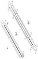
- FIG. 1Ais a perspective view illustrating a deflectable catheter assembly constructed in accordance with one embodiment.
- FIG. 1Bis a perspective view illustrating a deflectable catheter assembly constructed in accordance with one embodiment.
- FIG. 1Cis a perspective view illustrating a deflectable catheter assembly constructed in accordance with one embodiment.
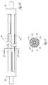
- FIG. 2is a cross-sectional view illustrating a portion of the deflectable catheter assembly constructed in accordance with one embodiment.
- FIG. 3is a cross-sectional view illustrating a portion of the deflectable catheter assembly constructed in accordance with one embodiment.
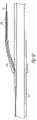
- FIG. 4is a perspective view illustrating a deflectable catheter body constructed in accordance with one embodiment.
- FIG. 5is a perspective view illustrating a distal portion of the deflectable catheter body constructed in accordance with one embodiment.
- FIG. 6is an end view of the distal end of the deflectable catheter assembly constructed in accordance with one embodiment.
- FIG. 7is a front view of the proximal end of the deflectable catheter assembly constructed in accordance with one embodiment.
- FIG. 8is a perspective view illustrating a tubular support member constructed in accordance with one embodiment.
- FIG. 9is a perspective view illustrating tubular support members telescopically engaged in accordance with one embodiment.
- FIG. 10is a side view illustrating tubular support members shown in FIG. 9 .
- FIG. 11is a cross-sectional view illustrating the tubular support members shown along line 11 - 11 in FIG. 10 .
- FIG. 12is a front view illustrating a tubular support member telescopically engaged in accordance with one embodiment.
- FIG. 13is a front view illustrating a tubular support member telescopically engaged in accordance with one embodiment.
- FIG. 14is a front view illustrating a tubular support member telescopically engaged in accordance with one embodiment.
- FIG. 15is a perspective view illustrating tubular support members telescopically engaged in accordance with one embodiment.
- FIG. 16is a perspective view illustrating a tubular support member engaged in accordance with one embodiment.
- FIG. 17is a perspective view illustrating tubular support members telescopically engaged in accordance with one embodiment.
- FIG. 18is a cross-sectional view illustrating tubular support members telescopically engaged in accordance with one embodiment.
- FIGS. 1A , 1 B and 1 Cillustrate a deflectable catheter assembly 100 , where FIG. 1A illustrates the deflectable catheter assembly 100 in one articulated position, and FIG. 1C illustrates the catheter assembly 100 in another articulated orientation.
- FIG. 1Billustrates the deflectable catheter assembly 100 in an unarticulated position.
- the deflectable catheter assembly 100includes a catheter body 110 and a handle assembly 150 that houses steering mechanisms for deflection of the catheter body 110 .
- the handle assembly 150allows for the selectable deflection of a distal end of the catheter body 110 into any number of disparate orientations.
- One example of the handle assembly 150is described in co-pending application Ser. No.
- FIGS. 2 and 3illustrate one option where a flexible element, such as a pull wire 120 , is connected to an actuator mechanism 130 that is slid or rotated to apply tension or compression to the pull wire 120 .
- a pull wire anchor(described below) at the distal end of the catheter body 110 is pulled or pushed causing the distal portion of the catheter body 110 to curve in predetermined directions.
- the catheter body 110comprises an elongate tubular construction that is flexible yet substantially non-compressible along its length.
- the deflectable catheter body 110extends from a proximal end 102 to a deflectable distal end 104 , where the deflectable distal end 104 is adapted to be disposed within a patient.
- a proximal tip 103At the proximal end 102 is a proximal tip 103 , and at the distal end 104 is a distal tip 105 .
- the physiciancontrols the deflection of the deflectable catheter body 110 with the handle assembly 150 ( FIGS. 1A , 1 B, 1 C, 2 and 3 ) containing the actuator mechanism 130 ( FIGS. 2 and 3 ) and a pull wire 120 ( FIGS. 2 and 3 ), as further described below.
- the distal end 104is deflected to traverse various branch vessels with the catheter assembly 100 ( FIGS. 1A and 1C ).
- FIG. 5illustrates a partial cut-away view of FIG. 4 , including the distal end 104 of the catheter body 110 .
- the catheter body 110includes a pull wire anchor 121 that is secured to the catheter body 110 .
- the pull wire 120is secured to the pull wire anchor 121 .
- the pull wire 120can be secured to the distal end 104 of the catheter body 110 by other means.
- the catheter body 110includes a stiffening member embedded therein, such as a braided stainless steel member 111 . The stiffening member facilitates rotation of the distal end 104 from the proximal end 102 , and also assists in preventing the catheter body 110 from collapsing.
- the pull wire 120is received within an actuator lumen 122 .
- the actuator lumen 122is disposed within the catheter body 110 and handle assembly 150 (see FIGS. 2 and 3 ).
- the pull wire 120is movably disposed within the actuator lumen 122 .
- the actuator lumen 122extends from a location near or at the distal end 104 (see FIG. 5 ) to an intermediate location that does not extend through the proximal end 102 (see FIG. 4 ). For example, as shown in FIG. 4 , when the pull wire 120 exits the catheter body 110 near the proximal end 102 the actuator lumen 122 consequently exits at a location in a side wall 124 of the catheter body 110 .
- FIG. 4when the pull wire 120 exits the catheter body 110 near the proximal end 102 the actuator lumen 122 consequently exits at a location in a side wall 124 of the catheter body 110 .
- FIG. 7illustrates an end view of the catheter body 110 at the proximal end 102 .
- the lumen 122does not extend to the proximal end 102 nor to the proximal tip 103 of the catheter body 110 . Therefore, there is no cross-contamination of fluids or gasses from a delivery lumen to the actuator lumen 122 , or vice versa.
- the actuator lumen 122extends through the proximal end 102 (see FIG. 4 ) and into the handle assembly 150 (see FIGS. 2 and 3 ).
- a first tubular support member 200is shown that is aligned along the longitudinal axis of the actuator lumen 122 .
- the first tubular support member 200presents one or more fingers 202 that extend from a base 204 parallel to a longitudinal axis of the member 200 .
- the first tubular support member 200is coupled with the pull wire 120 and fixedly coupled with the actuator mechanism 130 .
- the first tubular support member 200is fixedly coupled to the pull wire 120 .
- the first tubular support member 200is fixedly coupled to both the pull wire 120 and actuator mechanism 130 .
- the first tubular support member 200extends from a proximal end adjacent the actuator mechanism 130 to a distal end within actuator lumen 122 .
- the distal end of the first tubular support member 200is selectively positioned (described below) between the actuator mechanism 130 and the exit point (described above) of the pull wire 120 from catheter body 110 .
- the outer surfaces of the fingers 202 and base 204define a perimeter dimensioned and configured to enable the first tubular support member 200 to be housed within the actuator lumen 122 .
- the outer surfaces of the fingers 202 and base 204are dimensioned and configured to be coupled within an actuator lumen 122 having a circular cross-section.
- the fingers 202 and base 204have a substantially circular outer geometry so as to complement the circular actuator lumen 122 .
- the actuator lumen 122has a triangular cross-section geometry.
- the outer surfaces of the fingers 202 and base 204have a complementary triangular geometry so as to be snugly coupled within the triangular actuator lumen 122 .
- the actuator lumen 122has a cross-section geometry resembling an inverted ‘Y’ or three pointed star. Each ‘point’ of the actuator lumen 122 has a square furrow.
- the outer surfaces of the fingers 202 and base 204have a complementary square geometry so as to be snugly coupled within the actuator lumen 122 .
- the first tubular support member 200is a cylindrical member without fingers.
- a pull wire lumen 206is provided about the longitudinal axis of the first tubular support member 200 and extends through the base 204 .
- the inner surfaces of the fingers 202further define the pull wire lumen 206 .
- the pull wire 120is coupled to the inner surfaces of the fingers 202 and the base 204 within the pull wire lumen 206 .
- the first tubular support member 200is dimensioned and configured to restrain the pull wire 120 from moving laterally with respect to the longitudinal axis of the first tubular support member 200 .
- the diameter of the pull wire 120is only substantially similar or slightly smaller than the diameter of the pull wire lumen 206 , and thus the first tubular support member 200 prevents lateral movement of the pull wire 120 .
- the first tubular support member 200is telescopically coupled with a second tubular support member 208 .
- the second tubular support member 208has a complementary geometry to that of the first tubular support member 200 .
- the second tubular support member 208presents fingers 210 that extend from a base 212 parallel to a longitudinal axis of the member 208 .
- FIG. 11shows fingers 202 , 210 dimensioned and configured to slidably couple with each other and thereby allow telescoping movement between the first tubular support member 200 and the second tubular support member 208 .
- the fingers 210 and base 212 of the second tubular support member 208are dimensioned and configured to fit within the perimeter defined by the outer surfaces of the fingers 202 and base 204 of the first tubular support member 200 (described above).
- the second tubular support member 208is coupled to the housing 150 , disposed within the actuator lumen 122 , and aligned along the longitudinal axis of the actuator lumen 122 . As shown in FIG. 2 , the proximal end of the second tubular support member 208 is disposed within actuator lumen 122 adjacent to the location actuator mechanism 130 assumes when pull wire 120 is fully compressed.
- the second tubular support member 208extends from the proximal end to a distal end disposed where the actuator lumen 122 exits the catheter body 110 (described above).
- the first tubular support member 200 and second tubular support member 208have a substantially similar outer perimeter.
- the first tubular support member 200 and second tubular support member 208are dimensioned and configured to snugly couple with the surface defining the actuator lumen 122 .
- the first tubular support member 200 and second tubular support member 208are constructed from stainless steel, but may also be fabricated from other durable metals or plastics, including flexible materials.
- a pull wire lumen 214is provided in the second tubular support member 208 .
- the pull wire lumen 214is provided about the longitudinal axis of the second tubular support member 208 , extends through the base 212 and is further defined by the inner surfaces of the fingers 210 .
- the pull wire 120is received within the pull wire lumen 214 and is slidably coupled to the second tubular support member 208 therein.
- the pull wire 120is slidably coupled to the inner surfaces of the fingers 210 and the base 212 .
- the second tubular support member 208in one option, is dimensioned and configured to restrain the pull wire 120 from moving laterally with respect to the longitudinal axis of the second tubular support member 208 .
- the second tubular support member 208is a cylindrical member without fingers which has a complementary inner surface geometry to the outer surface of the first tubular support member 200 , and is therefore slidably coupled with the first tubular support member 200 to allow slidable movement therebetween.
- the second tubular support 208is formed on the catheter body 110 .
- the second tubular support member 208is coupled to the catheter body 110 and extends from a distal end where pull wire 120 exits the catheter body to a proximal end.
- the second tubular support member 208comprises at least a portion of the surface defining the actuator lumen 122 .
- the outer surface of the second tubular support member 208is coupled to the surface defining the actuator lumen 122 .
- the second tubular support member 208is plastic and overmolded onto the catheter body 110 .
- the second tubular support member 208has a complementary inner surface geometry to the outer surface of the first tubular support member 200 .
- the first tubular 200is therefore slidably coupled with the second tubular support member 208 to allow slidable movement therebetween.
- the pull wire 120is encapsulated with a sleeve including braided stainless steel impregnated with PTFE.
- the sleevesurrounds the first tubular member 200 , but is not bonded to the first tubular support member or the pull wire 120 .
- the second tubular support member 208bonds with the sleeve when overmolded onto the catheter body 110 . The sleeve prevents bonding of the second tubular support member 208 to the pull wire 120 and allows slidable movement between the first tubular support member 200 and second tubular support member.
- the first tubular support member 200 and second tubular support member 208proximately abut the pull wire 120 , but do not otherwise interfere with longitudinal movement of the pull wire 120 .
- the first tubular support member 200advances telescopically with respect to the second tubular support member 208 and actuator lumen 122 as it is fixedly coupled to the actuator mechanism 130 .
- the pull wire 120is specifically compressed, which occurs when it is desired that the catheter body 110 be oriented oppositely from an orientation caused with tension, this abutment by the tubular support members 200 , 208 braces the pull wire 120 and prevents it from buckling.
- the telescoping movement of the first tubular support member 200 with respect to the second tubular support member 208ensures that the compressed pull wire 120 is braced against buckling while the catheter body 110 is deflected to any degree.
- the cylindrical second tubular support member 208slidably couples with, but does not interfere with the movement of the cylindrical first tubular support member 200 (as described above).
- the first tubular support member 200is coupled to the pull wire 120 and fixedly coupled to the actuator mechanism 130 , but does not interfere with longitudinal movement of the pull wire 120 .
- the actuator 130applies tension or compression to the pull wire 120 so as to deflect the catheter body 110
- the first tubular support member 200moves telescopically with respect to the second tubular support member 208 as it is fixedly coupled to the actuator mechanism 130 .
- the pull wire 120When the pull wire 120 is specifically compressed, which occurs when it is desired that the catheter body 110 be oriented oppositely from an orientation caused with tension, the abutment by the first tubular support member 200 and the slidable coupling between the first tubular support member 200 and second tubular support member 208 braces the pull wire 120 and prevents it from buckling.
- a first tubular support member 200 having a triangular or inverted ‘Y’ geometry within a complementary actuator lumen 122is coupled to the pull wire 120 and is fixedly coupled to the actuator mechanism 130 , but does not interfere with longitudinal movement of the pull wire 120 .
- the actuator 130applies tension or compression to the pull wire 120 so as to deflect the catheter body 110
- the first tubular support member 200slidably moves within the actuator lumen 122 as it is fixedly coupled to the actuator mechanism 130 .
- the pull wire 120is specifically compressed, which occurs when it is desired that the catheter body 110 be oriented oppositely from an orientation caused with tension, the first tubular support member 200 braces the pull wire 120 and prevents it from buckling.
- a methodcomprises manipulating a deflectable catheter assembly into a first orientation, the deflectable catheter assembly including a catheter body and housing attached to the catheter body, an actuator lumen extends therein.
- the housingis attached to the catheter body proximal end, and a flexible element extends from an actuator member within the housing through the actuator lumen to a deflectable distal end.
- a first tubular support memberis coupled to the flexible element and fixedly coupled to the actuator member, and a second tubular support member is slidably coupled with the first tubular support member and slidably coupled to the flexible element. The first tubular support member and second tubular support member constrain lateral movement of the flexible element within the actuator lumen.
- the methodincludes longitudinally or telescopically advancing the flexible element and first tubular support member along the actuator lumen longitudinal axis.
- the second tubular support memberis stationary with respect to the housing and the first tubular support member and second tubular support member remain aligned with the actuator lumen longitudinal axis.
- the methodincludes further manipulating the actuator member to thereby actuate the flexible element and deflect the deflectable distal end into a disparate orientation.
- the methodincludes steering the deflectable catheter assembly which includes further manipulating the actuator member to deflect the deflectable distal end.
- manipulating the actuator member to deflect the deflectable distal end into a disparate orientationincludes constraining lateral movement of the flexible element within the actuator lumen with the first tubular support member and second tubular support member.
- further manipulating the actuator member to deflect the deflectable distal end into a disparate orientationincludes longitudinally advancing the flexible element and first tubular support member along the actuator lumen longitudinal axis, while the second tubular support member is stationary with respect to the housing, and the first tubular support member and second tubular support member remain aligned with the actuator lumen longitudinal axis.
- the above described deflectable catheterallows for bi-directional deflection of the catheter body using a single pull wire having a smaller diameter than what is otherwise required.
- the pull wire support assemblyprovides bracing for the narrow pull wire, when compressed, that prevents buckling due to articulation of the catheter into a disparate orientation from that caused by tensioning. Consequently, the pull wire and support assembly require significantly less volume within the catheter and leave additional space for the delivery lumen while allowing bi-directional deflection of the catheter.
Landscapes
- Health & Medical Sciences (AREA)
- Life Sciences & Earth Sciences (AREA)
- Engineering & Computer Science (AREA)
- Anesthesiology (AREA)
- Biophysics (AREA)
- Pulmonology (AREA)
- Mechanical Engineering (AREA)
- Biomedical Technology (AREA)
- Heart & Thoracic Surgery (AREA)
- Hematology (AREA)
- Animal Behavior & Ethology (AREA)
- General Health & Medical Sciences (AREA)
- Public Health (AREA)
- Veterinary Medicine (AREA)
- Media Introduction/Drainage Providing Device (AREA)
Abstract
Description
Claims (35)
Priority Applications (5)
| Application Number | Priority Date | Filing Date | Title |
|---|---|---|---|
| US10/670,150US7588555B2 (en) | 2003-09-24 | 2003-09-24 | Bi-directional catheter assembly and method therefor |
| PCT/US2004/031431WO2005030312A1 (en) | 2003-09-24 | 2004-09-24 | Bi-directional catheter assembly and method therefor |
| EP04789029.8AEP1663372B1 (en) | 2003-09-24 | 2004-09-24 | Bi-directional catheter assembly |
| CA2554549ACA2554549C (en) | 2003-09-24 | 2004-09-24 | Bi-directional catheter assembly and method therefor |
| US12/546,206US8007463B2 (en) | 2003-09-24 | 2009-08-24 | Bi-directional catheter assembly and method therefor |
Applications Claiming Priority (1)
| Application Number | Priority Date | Filing Date | Title |
|---|---|---|---|
| US10/670,150US7588555B2 (en) | 2003-09-24 | 2003-09-24 | Bi-directional catheter assembly and method therefor |
Related Child Applications (1)
| Application Number | Title | Priority Date | Filing Date |
|---|---|---|---|
| US12/546,206ContinuationUS8007463B2 (en) | 2003-09-24 | 2009-08-24 | Bi-directional catheter assembly and method therefor |
Publications (2)
| Publication Number | Publication Date |
|---|---|
| US20050065467A1 US20050065467A1 (en) | 2005-03-24 |
| US7588555B2true US7588555B2 (en) | 2009-09-15 |
Family
ID=34313839
Family Applications (2)
| Application Number | Title | Priority Date | Filing Date |
|---|---|---|---|
| US10/670,150Expired - LifetimeUS7588555B2 (en) | 2003-09-24 | 2003-09-24 | Bi-directional catheter assembly and method therefor |
| US12/546,206Expired - Fee RelatedUS8007463B2 (en) | 2003-09-24 | 2009-08-24 | Bi-directional catheter assembly and method therefor |
Family Applications After (1)
| Application Number | Title | Priority Date | Filing Date |
|---|---|---|---|
| US12/546,206Expired - Fee RelatedUS8007463B2 (en) | 2003-09-24 | 2009-08-24 | Bi-directional catheter assembly and method therefor |
Country Status (4)
| Country | Link |
|---|---|
| US (2) | US7588555B2 (en) |
| EP (1) | EP1663372B1 (en) |
| CA (1) | CA2554549C (en) |
| WO (1) | WO2005030312A1 (en) |
Cited By (9)
| Publication number | Priority date | Publication date | Assignee | Title |
|---|---|---|---|---|
| US20090312699A1 (en)* | 2003-09-24 | 2009-12-17 | Greatbach Ltd. | Bi-directional catheter assembly and method therefor |
| US20100228152A1 (en)* | 2006-08-18 | 2010-09-09 | Fisher William T | Catheter for conducting a procedure within a lumen, duct or organ of a living being |
| US8808345B2 (en) | 2008-12-31 | 2014-08-19 | Medtronic Ardian Luxembourg S.A.R.L. | Handle assemblies for intravascular treatment devices and associated systems and methods |
| US9050010B2 (en) | 2012-12-31 | 2015-06-09 | Biosense Webster (Israel) Ltd. | Double loop lasso with single puller wire for bi-directional actuation |
| US9433752B2 (en) | 2012-11-14 | 2016-09-06 | Biosense Webster (Israel) Ltd. | Catheter with flat beam deflection in tip |
| EP3725252A1 (en) | 2019-04-19 | 2020-10-21 | Lake Region Manufacturing, Inc. | Ablation catheter with fiber bragg grating strain sensors |
| EP3747354A1 (en) | 2019-06-07 | 2020-12-09 | Lake Region Manufacturing, Inc. | Basket-type ep catheter with electrode polling for sequential electrode sampling |
| US11471650B2 (en) | 2019-09-20 | 2022-10-18 | Biosense Webster (Israel) Ltd. | Mechanism for manipulating a puller wire |
| US11585706B2 (en) | 2020-10-14 | 2023-02-21 | Lake Region Manufacturing, Inc. | Guidewire with fiber Bragg grating strain sensors |
Families Citing this family (43)
| Publication number | Priority date | Publication date | Assignee | Title |
|---|---|---|---|---|
| US11083841B2 (en) | 2002-08-09 | 2021-08-10 | Fenwal, Inc. | Needle protector, needle assembly and fluid processing set including the same |
| US7497853B2 (en)* | 2005-05-05 | 2009-03-03 | Enpath Medical Inc. | Deflectable catheter steering and locking system |
| US20060270976A1 (en)* | 2005-05-31 | 2006-11-30 | Prorhythm, Inc. | Steerable catheter |
| US20060270975A1 (en)* | 2005-05-31 | 2006-11-30 | Prorhythm, Inc. | Steerable catheter |
| EP2491870A1 (en) | 2006-01-09 | 2012-08-29 | Cook Medical Technologies LLC | Deflectable tip access sheath |
| US7615044B2 (en)* | 2006-05-03 | 2009-11-10 | Greatbatch Ltd. | Deflectable sheath handle assembly and method therefor |
| US20090105815A1 (en)* | 2007-10-19 | 2009-04-23 | Matthew Krever | Push-in retainer system for use in the direct plication annuloplasty treatment of mitral valve regurgitation |
| US8197464B2 (en)* | 2007-10-19 | 2012-06-12 | Cordis Corporation | Deflecting guide catheter for use in a minimally invasive medical procedure for the treatment of mitral valve regurgitation |
| US9675369B2 (en)* | 2007-12-18 | 2017-06-13 | Boston Scientific Scimed, Inc. | Multi-functional medical device |
| WO2010075445A1 (en) | 2008-12-23 | 2010-07-01 | Silk Road Medical, Inc. | Methods and systems for treatment of acute ischemic stroke |
| EP2429427B1 (en) | 2009-05-14 | 2017-10-11 | Cook Medical Technologies LLC | Access sheath with active deflection |
| US8376991B2 (en)* | 2009-11-09 | 2013-02-19 | St. Jude Medical, Atrial Fibrillation Division, Inc. | Device for reducing axial shortening of catheter or sheath due to repeated deflection |
| USD650476S1 (en)* | 2011-05-25 | 2011-12-13 | Truphatek International Ltd. | Hand operated articulated intubation stylet |
| EP4101399B1 (en) | 2011-08-05 | 2025-04-09 | Route 92 Medical, Inc. | System for treatment of acute ischemic stroke |
| US10779855B2 (en) | 2011-08-05 | 2020-09-22 | Route 92 Medical, Inc. | Methods and systems for treatment of acute ischemic stroke |
| CN103071230B (en)* | 2013-01-28 | 2014-12-03 | 湖南埃普特医疗器械有限公司 | Controllable bent guiding catheter and manufacture method thereof |
| US9265512B2 (en) | 2013-12-23 | 2016-02-23 | Silk Road Medical, Inc. | Transcarotid neurovascular catheter |
| US9241699B1 (en) | 2014-09-04 | 2016-01-26 | Silk Road Medical, Inc. | Methods and devices for transcarotid access |
| US11027104B2 (en) | 2014-09-04 | 2021-06-08 | Silk Road Medical, Inc. | Methods and devices for transcarotid access |
| CN119949953A (en) | 2015-02-04 | 2025-05-09 | 92号医疗公司 | Intravascular access system, dilator and system including dilator |
| US10426497B2 (en)* | 2015-07-24 | 2019-10-01 | Route 92 Medical, Inc. | Anchoring delivery system and methods |
| US11065019B1 (en) | 2015-02-04 | 2021-07-20 | Route 92 Medical, Inc. | Aspiration catheter systems and methods of use |
| WO2017147493A1 (en) | 2016-02-24 | 2017-08-31 | Incept, Llc | Enhanced flexibility neurovascular catheter |
| JP7264581B2 (en) | 2017-01-06 | 2023-04-25 | インセプト、リミテッド、ライアビリティ、カンパニー | Antithrombotic coating for aneurysm treatment devices |
| CN110392591B (en) | 2017-01-10 | 2022-06-03 | 92号医疗公司 | Aspiration catheter system and method of use |
| US10864350B2 (en) | 2017-01-20 | 2020-12-15 | Route 92 Medical, Inc. | Single operator intracranial medical device delivery systems and methods of use |
| US11395665B2 (en) | 2018-05-01 | 2022-07-26 | Incept, Llc | Devices and methods for removing obstructive material, from an intravascular site |
| AU2019262972B2 (en) | 2018-05-01 | 2025-02-27 | Incept, Llc | Devices and methods for removing obstructive material from an intravascular site |
| JP7616642B2 (en) | 2018-05-17 | 2025-01-17 | ルート92メディカル・インコーポレイテッド | Suction catheter system and method of use |
| US11471582B2 (en) | 2018-07-06 | 2022-10-18 | Incept, Llc | Vacuum transfer tool for extendable catheter |
| US11517335B2 (en) | 2018-07-06 | 2022-12-06 | Incept, Llc | Sealed neurovascular extendable catheter |
| EP3903872B1 (en)* | 2018-12-29 | 2024-06-05 | Hangzhou Endonom Medtech Co., Ltd | Bendable catheter |
| US11766539B2 (en) | 2019-03-29 | 2023-09-26 | Incept, Llc | Enhanced flexibility neurovascular catheter |
| US11134859B2 (en) | 2019-10-15 | 2021-10-05 | Imperative Care, Inc. | Systems and methods for multivariate stroke detection |
| EP4076611A4 (en) | 2019-12-18 | 2023-11-15 | Imperative Care, Inc. | Methods and systems for treating venous thromboembolic disease |
| US20210316127A1 (en) | 2019-12-18 | 2021-10-14 | Imperative Care, Inc. | Hemostasis valve |
| US11638637B2 (en) | 2019-12-18 | 2023-05-02 | Imperative Care, Inc. | Method of removing embolic material with thrombus engagement tool |
| CN113747934B (en) | 2020-03-10 | 2024-07-09 | 因普瑞缇夫护理公司 | Enhanced flexibility neurovascular catheter |
| US11207497B1 (en) | 2020-08-11 | 2021-12-28 | Imperative Care, Inc. | Catheter with enhanced tensile strength |
| WO2022076893A1 (en) | 2020-10-09 | 2022-04-14 | Route 92 Medical, Inc. | Aspiration catheter systems and methods of use |
| US20220183664A1 (en) | 2020-12-10 | 2022-06-16 | Olympus Medical Systems Corporation | Real-time sampling system |
| US20230052862A1 (en) | 2021-08-12 | 2023-02-16 | Imperative Care, Inc. | Sterile packaging assembly for robotic interventional device |
| USD1077996S1 (en) | 2021-10-18 | 2025-06-03 | Imperative Care, Inc. | Inline fluid filter |
Citations (17)
| Publication number | Priority date | Publication date | Assignee | Title |
|---|---|---|---|---|
| US4898577A (en) | 1988-09-28 | 1990-02-06 | Advanced Cardiovascular Systems, Inc. | Guiding cathether with controllable distal tip |
| US5195968A (en)* | 1990-02-02 | 1993-03-23 | Ingemar Lundquist | Catheter steering mechanism |
| US5358478A (en) | 1990-02-02 | 1994-10-25 | Ep Technologies, Inc. | Catheter steering assembly providing asymmetric left and right curve configurations |
| US5545200A (en) | 1993-07-20 | 1996-08-13 | Medtronic Cardiorhythm | Steerable electrophysiology catheter |
| US5588964A (en)* | 1992-12-01 | 1996-12-31 | Cardiac Pathways Corporation | Steerable catheter with adjustable bend location and/or radius and method |
| US5642736A (en) | 1992-02-14 | 1997-07-01 | Avitall; Boaz | Biplanar deflectable catheter for arrhythmogenic tissue ablation |
| US5656030A (en)* | 1995-05-22 | 1997-08-12 | Boston Scientific Corporation | Bidirectional steerable catheter with deflectable distal tip |
| US5807249A (en)* | 1996-02-16 | 1998-09-15 | Medtronic, Inc. | Reduced stiffness, bidirectionally deflecting catheter assembly |
| US5826576A (en) | 1996-08-08 | 1998-10-27 | Medtronic, Inc. | Electrophysiology catheter with multifunction wire and method for making |
| US5897554A (en) | 1997-03-01 | 1999-04-27 | Irvine Biomedical, Inc. | Steerable catheter having a loop electrode |
| US5944690A (en) | 1997-03-17 | 1999-08-31 | C.R. Bard, Inc. | Slidable control mechanism for steerable catheter |
| EP1038545A2 (en) | 1999-03-22 | 2000-09-27 | Cordis Webster, Inc. | Multi-directional steerable catheters and control handles |
| US6171277B1 (en) | 1997-12-01 | 2001-01-09 | Cordis Webster, Inc. | Bi-directional control handle for steerable catheter |
| US6183463B1 (en) | 1997-12-01 | 2001-02-06 | Cordis Webster, Inc. | Bidirectional steerable cathether with bidirectional control handle |
| EP1205208A1 (en) | 2000-11-10 | 2002-05-15 | Biosense Webster, Inc. | Deflectable catheter with modifiable handle |
| US20030050598A1 (en)* | 2001-09-13 | 2003-03-13 | Hayzelden Robert C. | Adjustable profile steerable catheter |
| WO2005030312A1 (en) | 2003-09-24 | 2005-04-07 | Enpath Medical, Inc. | Bi-directional catheter assembly and method therefor |
Family Cites Families (3)
| Publication number | Priority date | Publication date | Assignee | Title |
|---|---|---|---|---|
| DE3738106C2 (en)* | 1987-11-10 | 1995-06-22 | Helmut Fischer Gmbh & Co | Device for a hardness measuring device |
| US5030204A (en)* | 1988-09-28 | 1991-07-09 | Advanced Cardiovascular Systems, Inc. | Guiding catheter with controllable distal tip |
| US5168864A (en)* | 1991-09-26 | 1992-12-08 | Clarus Medical Systems, Inc. | Deflectable endoscope |
- 2003
- 2003-09-24USUS10/670,150patent/US7588555B2/ennot_activeExpired - Lifetime
- 2004
- 2004-09-24EPEP04789029.8Apatent/EP1663372B1/ennot_activeExpired - Lifetime
- 2004-09-24CACA2554549Apatent/CA2554549C/ennot_activeExpired - Lifetime
- 2004-09-24WOPCT/US2004/031431patent/WO2005030312A1/enactiveApplication Filing
- 2009
- 2009-08-24USUS12/546,206patent/US8007463B2/ennot_activeExpired - Fee Related
Patent Citations (17)
| Publication number | Priority date | Publication date | Assignee | Title |
|---|---|---|---|---|
| US4898577A (en) | 1988-09-28 | 1990-02-06 | Advanced Cardiovascular Systems, Inc. | Guiding cathether with controllable distal tip |
| US5195968A (en)* | 1990-02-02 | 1993-03-23 | Ingemar Lundquist | Catheter steering mechanism |
| US5358478A (en) | 1990-02-02 | 1994-10-25 | Ep Technologies, Inc. | Catheter steering assembly providing asymmetric left and right curve configurations |
| US5642736A (en) | 1992-02-14 | 1997-07-01 | Avitall; Boaz | Biplanar deflectable catheter for arrhythmogenic tissue ablation |
| US5588964A (en)* | 1992-12-01 | 1996-12-31 | Cardiac Pathways Corporation | Steerable catheter with adjustable bend location and/or radius and method |
| US5545200A (en) | 1993-07-20 | 1996-08-13 | Medtronic Cardiorhythm | Steerable electrophysiology catheter |
| US5656030A (en)* | 1995-05-22 | 1997-08-12 | Boston Scientific Corporation | Bidirectional steerable catheter with deflectable distal tip |
| US5807249A (en)* | 1996-02-16 | 1998-09-15 | Medtronic, Inc. | Reduced stiffness, bidirectionally deflecting catheter assembly |
| US5826576A (en) | 1996-08-08 | 1998-10-27 | Medtronic, Inc. | Electrophysiology catheter with multifunction wire and method for making |
| US5897554A (en) | 1997-03-01 | 1999-04-27 | Irvine Biomedical, Inc. | Steerable catheter having a loop electrode |
| US5944690A (en) | 1997-03-17 | 1999-08-31 | C.R. Bard, Inc. | Slidable control mechanism for steerable catheter |
| US6171277B1 (en) | 1997-12-01 | 2001-01-09 | Cordis Webster, Inc. | Bi-directional control handle for steerable catheter |
| US6183463B1 (en) | 1997-12-01 | 2001-02-06 | Cordis Webster, Inc. | Bidirectional steerable cathether with bidirectional control handle |
| EP1038545A2 (en) | 1999-03-22 | 2000-09-27 | Cordis Webster, Inc. | Multi-directional steerable catheters and control handles |
| EP1205208A1 (en) | 2000-11-10 | 2002-05-15 | Biosense Webster, Inc. | Deflectable catheter with modifiable handle |
| US20030050598A1 (en)* | 2001-09-13 | 2003-03-13 | Hayzelden Robert C. | Adjustable profile steerable catheter |
| WO2005030312A1 (en) | 2003-09-24 | 2005-04-07 | Enpath Medical, Inc. | Bi-directional catheter assembly and method therefor |
Non-Patent Citations (5)
Cited By (19)
| Publication number | Priority date | Publication date | Assignee | Title |
|---|---|---|---|---|
| US8007463B2 (en) | 2003-09-24 | 2011-08-30 | Greatbatch Ltd. | Bi-directional catheter assembly and method therefor |
| US20090312699A1 (en)* | 2003-09-24 | 2009-12-17 | Greatbach Ltd. | Bi-directional catheter assembly and method therefor |
| US20100228152A1 (en)* | 2006-08-18 | 2010-09-09 | Fisher William T | Catheter for conducting a procedure within a lumen, duct or organ of a living being |
| US8721626B2 (en)* | 2006-08-18 | 2014-05-13 | Kensey Nash Corporation | Catheter for conducting a procedure within a lumen, duct or organ of a living being |
| US8808345B2 (en) | 2008-12-31 | 2014-08-19 | Medtronic Ardian Luxembourg S.A.R.L. | Handle assemblies for intravascular treatment devices and associated systems and methods |
| US9433752B2 (en) | 2012-11-14 | 2016-09-06 | Biosense Webster (Israel) Ltd. | Catheter with flat beam deflection in tip |
| US9974927B2 (en) | 2012-11-14 | 2018-05-22 | Biosense Webster (Israel) Ltd. | Catheter with flat beam deflection in tip |
| US9918791B2 (en) | 2012-12-31 | 2018-03-20 | Biosense Webster (Israel) Ltd. | Double loop lasso with single puller wire for bi-directional actuation |
| US9326818B2 (en) | 2012-12-31 | 2016-05-03 | Biosense Webster (Israel) Ltd. | Double loop lasso with single puller wire for bi-directional actuation |
| US9050010B2 (en) | 2012-12-31 | 2015-06-09 | Biosense Webster (Israel) Ltd. | Double loop lasso with single puller wire for bi-directional actuation |
| US10485610B2 (en) | 2012-12-31 | 2019-11-26 | Biosense Webster (Israel) Ltd. | Double loop lasso with single puller wire for bi-directional actuation |
| US10898264B2 (en) | 2012-12-31 | 2021-01-26 | Biosense Webster (Israel) Ltd. | Double loop lasso with single puller wire for bi-directional actuation |
| US12133677B2 (en) | 2012-12-31 | 2024-11-05 | Biosense Webster (Israel) Ltd. | Double loop lasso with single puller wire for bi-directional actuation |
| EP3725252A1 (en) | 2019-04-19 | 2020-10-21 | Lake Region Manufacturing, Inc. | Ablation catheter with fiber bragg grating strain sensors |
| US11357570B2 (en) | 2019-04-19 | 2022-06-14 | Lake Region Manufacturing, Inc. | Ablation catheter with fiber Bragg grating strain sensors |
| EP3747354A1 (en) | 2019-06-07 | 2020-12-09 | Lake Region Manufacturing, Inc. | Basket-type ep catheter with electrode polling for sequential electrode sampling |
| US11471650B2 (en) | 2019-09-20 | 2022-10-18 | Biosense Webster (Israel) Ltd. | Mechanism for manipulating a puller wire |
| US11964115B2 (en) | 2019-09-20 | 2024-04-23 | Biosense Webster (Israel) Ltd. | Mechanism for manipulating a puller wire |
| US11585706B2 (en) | 2020-10-14 | 2023-02-21 | Lake Region Manufacturing, Inc. | Guidewire with fiber Bragg grating strain sensors |
Also Published As
| Publication number | Publication date |
|---|---|
| US8007463B2 (en) | 2011-08-30 |
| US20050065467A1 (en) | 2005-03-24 |
| CA2554549A1 (en) | 2005-04-07 |
| CA2554549C (en) | 2010-06-29 |
| US20090312699A1 (en) | 2009-12-17 |
| WO2005030312A1 (en) | 2005-04-07 |
| EP1663372B1 (en) | 2016-06-01 |
| EP1663372A1 (en) | 2006-06-07 |
Similar Documents
| Publication | Publication Date | Title |
|---|---|---|
| US7588555B2 (en) | Bi-directional catheter assembly and method therefor | |
| US4723936A (en) | Steerable catheter | |
| US5908395A (en) | Vibrating guidewire | |
| US5125895A (en) | Steerable catheter | |
| EP1942975B1 (en) | Steerable catheter devices and methods of articulating catheter devices | |
| US4586923A (en) | Curving tip catheter | |
| US6264630B1 (en) | Balloon catheter having an oscillating tip configuration | |
| US6447501B1 (en) | Enhanced stent delivery system | |
| US5399164A (en) | Catheter having a multiple durometer | |
| US5306245A (en) | Articulating device | |
| EP1515771B1 (en) | Catheter assembly with side wall exit and method of manufacture | |
| US6394995B1 (en) | Enhanced balloon dilatation system | |
| US5344397A (en) | Cholangiogram catheter | |
| US6740104B1 (en) | Enhanced catheter with alignment means | |
| US5376083A (en) | Steerable infusion guide wire | |
| US5059176A (en) | Vascular system steerable guidewire with inflatable balloon | |
| EP0398956A1 (en) | Steerable guidewire for vascular system | |
| US20070260225A1 (en) | Steerable sheath actuator | |
| US20050107737A1 (en) | Bidirectional steerable catheter with slidable mated puller wires | |
| EP1885427B1 (en) | Articulating handle for a deflectable catheter and method therefor | |
| JP2014520598A (en) | Steerable delivery catheter | |
| EP0125293A4 (en) | Double lumen dilatation catheter. | |
| US5409455A (en) | Vascular navigation and visualization assist device | |
| US20090209941A1 (en) | Implant deployment catheter | |
| JP2006110061A (en) | Catheter |
Legal Events
| Date | Code | Title | Description |
|---|---|---|---|
| AS | Assignment | Owner name:ENPATH MEDICAL INCORPORATED, MINNESOTA Free format text:ASSIGNMENT OF ASSIGNORS INTEREST;ASSIGNORS:PUDELKO, GREG;FISCHER, BRIAN;HONEBRINK, BRIAN;REEL/FRAME:014993/0104;SIGNING DATES FROM 20040211 TO 20040212 | |
| AS | Assignment | Owner name:ENPATH MEDICAL, INC., MINNESOTA Free format text:CHANGE OF NAME;ASSIGNOR:MEDAMICUS, INC.;REEL/FRAME:015328/0301 Effective date:20040124 | |
| AS | Assignment | Owner name:QUAN EMERTEQ CORP., MINNESOTA Free format text:ASSIGNMENT OF ASSIGNORS INTEREST;ASSIGNOR:ENPATH MEDICAL, INC.;REEL/FRAME:020617/0788 Effective date:20080310 | |
| FEPP | Fee payment procedure | Free format text:PAYOR NUMBER ASSIGNED (ORIGINAL EVENT CODE: ASPN); ENTITY STATUS OF PATENT OWNER: LARGE ENTITY | |
| AS | Assignment | Owner name:GREATBATCH LTD.,NEW YORK Free format text:ASSIGNMENT OF ASSIGNORS INTEREST;ASSIGNOR:QUAN EMERTEQ CORP.;REEL/FRAME:022063/0692 Effective date:20081230 Owner name:GREATBATCH LTD., NEW YORK Free format text:ASSIGNMENT OF ASSIGNORS INTEREST;ASSIGNOR:QUAN EMERTEQ CORP.;REEL/FRAME:022063/0692 Effective date:20081230 | |
| STCF | Information on status: patent grant | Free format text:PATENTED CASE | |
| FEPP | Fee payment procedure | Free format text:PAT HOLDER NO LONGER CLAIMS SMALL ENTITY STATUS, ENTITY STATUS SET TO UNDISCOUNTED (ORIGINAL EVENT CODE: STOL); ENTITY STATUS OF PATENT OWNER: LARGE ENTITY | |
| FPAY | Fee payment | Year of fee payment:4 | |
| AS | Assignment | Owner name:MANUFACTURERS AND TRADERS TRUST COMPANY, NEW YORK Free format text:SECURITY INTEREST;ASSIGNORS:GREATBATCH, INC.;GREATBATCH LTD.;ELECTROCHEM SOLUTIONS, INC.;AND OTHERS;REEL/FRAME:036980/0482 Effective date:20151027 | |
| FPAY | Fee payment | Year of fee payment:8 | |
| MAFP | Maintenance fee payment | Free format text:PAYMENT OF MAINTENANCE FEE, 12TH YEAR, LARGE ENTITY (ORIGINAL EVENT CODE: M1553); ENTITY STATUS OF PATENT OWNER: LARGE ENTITY Year of fee payment:12 | |
| AS | Assignment | Owner name:WELLS FARGO BANK, NATIONAL ASSOCIATION, AS ADMINISTRATIVE AGENT, VIRGINIA Free format text:SECURITY INTEREST;ASSIGNORS:GREATBATCH LTD.;ELECTROCHEM SOLUTIONS, INC.;LAKE REGION MEDICAL, INC.;AND OTHERS;REEL/FRAME:057468/0056 Effective date:20210902 | |
| AS | Assignment | Owner name:MICRO POWER ELECTRONICS, INC., NEW YORK Free format text:RELEASE BY SECURED PARTY;ASSIGNOR:MANUFACTURERS AND TRADERS TRUST COMPANY (AS ADMINISTRATIVE AGENT);REEL/FRAME:060938/0069 Effective date:20210903 Owner name:PRECIMED INC., NEW YORK Free format text:RELEASE BY SECURED PARTY;ASSIGNOR:MANUFACTURERS AND TRADERS TRUST COMPANY (AS ADMINISTRATIVE AGENT);REEL/FRAME:060938/0069 Effective date:20210903 Owner name:GREATBATCH-GLOBE TOOL, INC., NEW YORK Free format text:RELEASE BY SECURED PARTY;ASSIGNOR:MANUFACTURERS AND TRADERS TRUST COMPANY (AS ADMINISTRATIVE AGENT);REEL/FRAME:060938/0069 Effective date:20210903 Owner name:NEURONEXUS TECHNOLOGIES, INC., NEW YORK Free format text:RELEASE BY SECURED PARTY;ASSIGNOR:MANUFACTURERS AND TRADERS TRUST COMPANY (AS ADMINISTRATIVE AGENT);REEL/FRAME:060938/0069 Effective date:20210903 Owner name:ELECTROCHEM SOLUTIONS, INC., NEW YORK Free format text:RELEASE BY SECURED PARTY;ASSIGNOR:MANUFACTURERS AND TRADERS TRUST COMPANY (AS ADMINISTRATIVE AGENT);REEL/FRAME:060938/0069 Effective date:20210903 Owner name:GREATBATCH LTD., NEW YORK Free format text:RELEASE BY SECURED PARTY;ASSIGNOR:MANUFACTURERS AND TRADERS TRUST COMPANY (AS ADMINISTRATIVE AGENT);REEL/FRAME:060938/0069 Effective date:20210903 Owner name:GREATBATCH, INC., NEW YORK Free format text:RELEASE BY SECURED PARTY;ASSIGNOR:MANUFACTURERS AND TRADERS TRUST COMPANY (AS ADMINISTRATIVE AGENT);REEL/FRAME:060938/0069 Effective date:20210903 | |
| AS | Assignment | Owner name:MICRO POWER ELECTRONICS, INC., NEW YORK Free format text:RELEASE BY SECURED PARTY;ASSIGNOR:MANUFACTURERS AND TRADERS TRUST COMPANY (AS ADMINISTRATIVE AGENT);REEL/FRAME:061659/0858 Effective date:20210903 Owner name:PRECIMED INC., NEW YORK Free format text:RELEASE BY SECURED PARTY;ASSIGNOR:MANUFACTURERS AND TRADERS TRUST COMPANY (AS ADMINISTRATIVE AGENT);REEL/FRAME:061659/0858 Effective date:20210903 Owner name:GREATBATCH-GLOBE TOOL, INC., NEW YORK Free format text:RELEASE BY SECURED PARTY;ASSIGNOR:MANUFACTURERS AND TRADERS TRUST COMPANY (AS ADMINISTRATIVE AGENT);REEL/FRAME:061659/0858 Effective date:20210903 Owner name:NEURONEXUS TECHNOLOGIES, INC., NEW YORK Free format text:RELEASE BY SECURED PARTY;ASSIGNOR:MANUFACTURERS AND TRADERS TRUST COMPANY (AS ADMINISTRATIVE AGENT);REEL/FRAME:061659/0858 Effective date:20210903 Owner name:ELECTROCHEM SOLUTIONS, INC., NEW YORK Free format text:RELEASE BY SECURED PARTY;ASSIGNOR:MANUFACTURERS AND TRADERS TRUST COMPANY (AS ADMINISTRATIVE AGENT);REEL/FRAME:061659/0858 Effective date:20210903 Owner name:GREATBATCH LTD., NEW YORK Free format text:RELEASE BY SECURED PARTY;ASSIGNOR:MANUFACTURERS AND TRADERS TRUST COMPANY (AS ADMINISTRATIVE AGENT);REEL/FRAME:061659/0858 Effective date:20210903 Owner name:GREATBATCH, INC., NEW YORK Free format text:RELEASE BY SECURED PARTY;ASSIGNOR:MANUFACTURERS AND TRADERS TRUST COMPANY (AS ADMINISTRATIVE AGENT);REEL/FRAME:061659/0858 Effective date:20210903 |