US7587072B2 - System for and method of generating rotational inputs - Google Patents
System for and method of generating rotational inputsDownload PDFInfo
- Publication number
- US7587072B2 US7587072B2US10/912,655US91265504AUS7587072B2US 7587072 B2US7587072 B2US 7587072B2US 91265504 AUS91265504 AUS 91265504AUS 7587072 B2US7587072 B2US 7587072B2
- Authority
- US
- United States
- Prior art keywords
- image
- sensor
- patterned
- correlating
- linear
- Prior art date
- Legal status (The legal status is an assumption and is not a legal conclusion. Google has not performed a legal analysis and makes no representation as to the accuracy of the status listed.)
- Expired - Lifetime, expires
Links
Images


Classifications
- G—PHYSICS
- G06—COMPUTING OR CALCULATING; COUNTING
- G06F—ELECTRIC DIGITAL DATA PROCESSING
- G06F3/00—Input arrangements for transferring data to be processed into a form capable of being handled by the computer; Output arrangements for transferring data from processing unit to output unit, e.g. interface arrangements
- G06F3/01—Input arrangements or combined input and output arrangements for interaction between user and computer
- G06F3/03—Arrangements for converting the position or the displacement of a member into a coded form
- G06F3/033—Pointing devices displaced or positioned by the user, e.g. mice, trackballs, pens or joysticks; Accessories therefor
- G06F3/0354—Pointing devices displaced or positioned by the user, e.g. mice, trackballs, pens or joysticks; Accessories therefor with detection of 2D relative movements between the device, or an operating part thereof, and a plane or surface, e.g. 2D mice, trackballs, pens or pucks
- G06F3/03547—Touch pads, in which fingers can move on a surface
- G—PHYSICS
- G06—COMPUTING OR CALCULATING; COUNTING
- G06V—IMAGE OR VIDEO RECOGNITION OR UNDERSTANDING
- G06V40/00—Recognition of biometric, human-related or animal-related patterns in image or video data
- G06V40/10—Human or animal bodies, e.g. vehicle occupants or pedestrians; Body parts, e.g. hands
- G06V40/12—Fingerprints or palmprints
- G06V40/1335—Combining adjacent partial images (e.g. slices) to create a composite input or reference pattern; Tracking a sweeping finger movement
- G—PHYSICS
- G06—COMPUTING OR CALCULATING; COUNTING
- G06F—ELECTRIC DIGITAL DATA PROCESSING
- G06F2203/00—Indexing scheme relating to G06F3/00 - G06F3/048
- G06F2203/033—Indexing scheme relating to G06F3/033
- G06F2203/0338—Fingerprint track pad, i.e. fingerprint sensor used as pointing device tracking the fingertip image
Definitions
- This inventionrelates to the field of biometric sensors.
- this inventionrelates to systems and methods that use fingerprint images to emulate electronic positioning devices.
- Portable electronic computing platformsneed these user inputs for multiple purposes, including (a) navigating a cursor or a pointer to a certain location on a display, (b) selecting (e.g., choosing or not choosing) an item or an action, and (c) orientating (e.g., changing direction with or without visual feedback) an input device.
- Prior art methodscalculate rotation by rotating one frame with respect to another and then applying standard correlation methods. These methods require the selection of a pivot point (e.g., the origin), followed by additional computations. These computations are not helpful for determining linear motion (e.g., non-rotational movement in the x- and y-directions). Such a shortcoming makes prior art systems even more inefficient when used in portable devices, in which both rotational and linear movement are required, such as when emulating, respectively, a steering wheel and a pointing device.
- the present inventiondiscloses a system for and method of obtaining rotation information from a patterned image, such as a fingerprint image.
- Embodiments of the present inventionthus require smaller footprints than those that use joy sticks, steering wheels, and other, larger devices that require additional power.
- Embodiments of the present inventionuse linear correlation methods that are easier to use than rotational and other methods such as those using trigonometric functions.
- Embodiments of the present inventionthus use simpler algorithms that can be performed faster and more reliably.
- a method of obtaining rotation informationcomprises capturing a plurality of patterned images from a plurality of locations, correlating the plurality of patterned images to generate sets of linear differences, and using the sets of linear differences to generate the rotation information.
- the plurality of locationscomprise a first part of a sensor and a second part of the sensor. A first of the plurality of patterned images is captured in the first part of the sensor and a second of the plurality of patterned images is captured in the second part of the sensor.
- the senoris a biometric image sensor, such as a finger image sensor.
- the first of the plurality of patterned images and the second of the plurality of patterned images togethercorrespond to a fingerprint image in a first position on the sensor.
- a third of the plurality of patterned imagesis captured in the first part of the sensor and a fourth of the plurality of patterned images is captured in the second part of the sensor.
- the third of the plurality of patterned images and the fourth of the plurality of patterned images togethercorrespond to the fingerprint image in a second position on the sensor.
- the rotation informationcorresponds to an angular difference between the first position and the second position.
- correlating the plurality of patterned imagescomprises correlating the first patterned image with the third patterned image to generate a first set of linear differences from the sets of linear differences, correlating the second patterned image with the fourth patterned image to generate a second set of linear differences from the sets of linear differences, and correlating a first combination of the first patterned image and the second patterned image with a second combination of the third patterned image and the fourth patterned image to generate a third set of linear differences from the sets of linear differences.
- Correlating the first patterned image with the third patterned image, correlating the second patterned image with the fourth patterned image, and correlating the first combination with the second combinationall comprise performing a cross correlation.
- the cross correlationis either a normalized cross correlation or a standardized cross correlation.
- first part of the sensor and the second part of the sensorare contiguous.
- first part of the sensor and the second part of the sensorare not contiguous.
- the first part of the sensorcomprises a first sub-frame of pixels and the second part of the sensor comprises a second sub-frame of pixels.
- capturing the first patterned imagecomprises storing in the first sub-frame first data corresponding to the first patterned image
- capturing the second patterned imagecomprises storing in the second sub-frame second data corresponding to the second patterned image
- capturing the third patterned imagecomprises storing in the first sub-frame third data corresponding to the third patterned image
- capturing the fourth patterned imagecomprises storing in the second sub-frame fourth data corresponding to the fourth patterned image.
- Correlating the first patterned image with the third patterned imagecomprises correlating the first data with the third data to generate first and second linear differences from the first set of linear differences.
- Correlating the second patterned image with the fourth patterned imagecomprises correlating the second data with the fourth data to generate first and second linear differences from the second set of linear differences.
- correlating the first combination with the second combinationcomprises correlating a combination of the first data and the second data with a combination of the third data and the fourth data to generate first and second linear differences from the third set of linear differences.
- correlatingcomprises determining a lag to correlate elements of one of the first and second sub-frames, the lag and a difference between the elements corresponding to first and second linear differences from one of the sets of linear differences.
- Each elementcorresponds to a row of one of the first and second sub-frames.
- each elementcorresponds to a column of one of the first and second sub-frames.
- the methodfurther comprises filtering the first set of linear differences, the second set of linear differences, the third set of linear differences, and the rotation information. Filtering comprises multiplying by a scaling factor, performing a smoothing function, and performing a clipping function.
- the finger image sensoris a finger swipe sensor.
- the finger image sensoris a finger placement sensor.
- the methodfurther comprises using the rotation information on a host platform having a display screen, the rotation information used to rotate an object on the display screen, thereby emulating a computer input device.
- the computer input deviceis selected from the group consisting of a steering wheel, a joystick, and a navigation bar.
- Emulating a computer input devicecomprises moving the object on the display screen at a rate related to the angular difference or the angular position.
- a system for obtaining rotation informationcomprises means for capturing a plurality of patterned images from a plurality of locations and means for correlating the plurality of patterned images to generate sets of linear differences and for using the sets of linear differences to generate the rotation information.
- a method of emulating a rotational device using a patterncomprises capturing a first image of the pattern at a first orientation, capturing a second image of the pattern at a second orientation, correlating the first image with the second image to calculate linear differences between the first orientation and the second orientation, translating the linear difference into rotational data, and using the rotational data to emulate the movement of a rotational device.
- a system for emulating a positional devicecomprises a sensor for capturing an image of a pattern and a processor coupled to the sensor.
- the processoris configured to calculate linear differences between a first position of the image of the pattern and a second position of the image of the pattern and to translate the linear differences into rotational data corresponding to a rotation of the image of the pattern.
- a method of sensing rotation of an object on an image sensorcomprises sensing a first image of the object, sensing a second image of the object, and comparing the first image with the second image to determine whether there is linear motion in each of at least two portions of an area containing the first image and the second image to determine whether the object remained stationary, moved in a linear manner, or rotated.
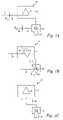
- FIGS. 1A and 1Bshow how an electronic image is rotated by rotating a finger on a finger image sensor, in accordance with the present invention.
- FIGS. 1Cshows a finger image sensor, processor, and display device in accordance with one embodiment of the present invention.
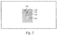
- FIG. 2shows a fingerprint image where ridges are shown in black and valleys are shown in white and indicating areas of bifurcation and ridge endings.
- FIGS. 3A-Dshows left- and right-hand sections of a fingerprint sensor with a portion of a fingerprint image placed upon it as the fingerprint image is linearly moved and rotated in accordance with the present invention.
- FIG. 4is a flowchart of a frame acquisition and image correlation procedure in accordance with the present invention.
- FIG. 5Ashows a finger image sensor in a horizontal orientation.
- FIG. 5Bshows a finger image sensor in a vertical orientation.
- FIG. 6shows pixel data from a frame (slice) from a fingerprint sensor.
- FIG. 7shows pixel data from a fingerprint sensor during different iterations of reconstruction in accordance with the present invention.
- FIGS. 8-12show different partition configurations of a frame in accordance with the present invention.
- the present inventionis directed to systems for and methods of determining the rotational position and movement of an arbitrary patterned material imaged by an imaging sensor.
- the arbitrary patterned materialis a finger and the rotational position and movement of the image of the finger are determined.
- Embodiments of the present inventionadvantageously determine and collect finger rotational information for use in a digital device and most preferably in personal computing devices. Unlike prior art rotational position correlators, which are non-linear, requiring trigonometric functions like sine, cosine, and tangent calculations, embodiments of the present invention use a linear correlation method that is easier to implement and more computationally efficient. Embodiments of the present invention allow for extremely efficient calculation of linear motion from the components used to determine the rotational motion, thereby reducing the complexity of systems that require one sensor to be used to gather both linear and rotational movement inputs.
- a system in accordance with embodiments of the present inventionreconstructs fingerprint images from swipe sensors, thereby efficiently providing rotational motion data along with data necessary to reconstruct the image.
- the systemis particularly well suited for applications that do not require high precision rotational information.
- Methods of and systems for fingerprint sensingare described in detail in the U.S. patent application Ser. No. 10/194,994, filed Jul. 12, 2002, and titled “Method and System for Biometric Image Assembly from Multiple Partial Biometric Frame Scans,” and in the U.S. patent application Ser. No. 10/099,558, filed Mar. 13, 2002, and titled “Fingerprint Biometric Capture Device and Method with Integrated On-Chip Data Buffering,” both of which are hereby incorporated by reference in their entireties.
- the fingerprint sensoris an Atrua Wings ATW 100 capacitive swipe sensor by Atrua Technologies, Inc., at 1696 Dell Avenue, Campbell, California 95008.
- a key aspect of the present inventionis determining rotation from linear correlation rather than prior art methods that determine rotation by rotating one frame with respect to another, and then applying standard correlation methods.
- the prior art methodsrequire choosing a pivot point (center of origin) and then performing additional computation.
- Such computationis not helpful for determining linear motion (non-rotational movement in the x- and y-directions). These computations are even more inefficient in portable electronic devices where it may be important to calculate both kinds of movement, for instance, when emulating a pointing device and a steering wheel on one component.
- Embodiments of the present inventionmake use of the fact that, as a finger rotates clockwise, the left side of the image of the finger will appear to be moving upward, while the right half of the image will appear to be moving downward. This is sometimes referred to as shear. The opposite is true of counterclockwise motion. Furthermore, in both cases, the left side will appear to be moving toward the right, and the right side will appear to be moving toward the left, as shown in FIGS. 3B and 3C .
- embodiments of the present inventionuse the simpler linear correlation methods to determine rotational movement, which will occur when motion of the left side of a finger image is in an opposite direction to that of the right side For instance, if the left half is moving upward and the right half downward, there is clockwise rotational movement as shown in FIG. 3D , discussed below. If the linear movement detected at the left edge and right edge of the sensor are substantially equal but opposite, the center of rotation is at or near the center of the sensor. If the linear movement is not equal but opposite, the center of rotation can be calculated and will be closer to the end of the sensor with the smaller amount of linear movement. If the linear movement is not equal but opposite, the center of rotation can be calculated.
- the present inventionoffers a reliable and computationally-efficient solution to obtain high-resolution rotational information about a user's finger as it contacts a finger imaging sensor, so that such a sensor can, for example, emulate a steering wheel for use in gaming, or rotate the image of a map for easier viewing on a display.
- FIG. 1Ashows a system 10 used to illustrate one embodiment of the present invention.
- the system 10comprises a finger image sensor 25 coupled to a display device 11 , displaying a triangular electronic image 15 .
- the display device 11can be a monitor used with a personal computer, a screen on a personal digital assistant (PDA) or game device, or any other kind of display device.
- FIG. 1Aalso shows a finger 30 placed on the finger image sensor 25 . It will be appreciated that the finger 30 has patterns on a surface contacting the finger image sensor 25 and that the finger image sensor 25 captures images of those patterns.
- a coordinate axis 20makes angle ⁇ 0 with and edge 21 of the triangular image 15 .
- a coordinate axis 35makes an angle ⁇ 0 with a line segment 36 associated with the finger 30 .
- FIG. 1Bshows the system 10 after the finger 30 has been rotated so that the coordinate axis 35 makes an angle ⁇ 1 with the line segment 36 .
- the triangular image 15is rotated so that the coordinate axis 20 makes an angle ⁇ 1 with the edge 21 .
- rotating the finger 30 through an angle ⁇ 1 - ⁇ 0 ( ⁇ )results in rotating the triangular electronic image through an angle ⁇ 1 - ⁇ 0 ( ⁇ ).
- ⁇can correspond to ⁇ in any number of ways.
- ⁇can equal ⁇
- ⁇can be a multiple of ⁇
- ⁇can be a fraction of ⁇
- ⁇can be a multiple of ⁇ plus some offset, etc.
- the finger 30does not have to maintain a pivot point on the finger image sensor 25 .
- the finger 30can be moved horizontally or vertically on the finger image sensor 25 before, while, or after it is rotated so that the line segment 36 is displaced horizontally, or vertically, or both, and the angle ⁇ still determined.
- vertical and horizontal movements of the finger 30can also captured to vertically and horizontally displace the triangular image 15 on the display device 11 .
- the triangular image 15can be moved at a rate related to ⁇ (called the rate mode) or at a rate related to ⁇ 1 .
- the finger image sensor 25is depicted as a placement sensor, it will be appreciated that other types of sensors can be used in accordance with the present invention.
- the finger image sensor 25is a swipe sensor, described in more detail below.
- FIG. 1Cshows one embodiment of the present invention that includes a processor 50 coupling the finger image sensor 25 to the display device 11 .
- the processor 50is configured to correlate multiple patterns of an image of the finger 30 captured on the finger image sensor 25 , to thereby determine linear differences between the multiple patterns. As described in more detail below, the linear differences are used to determine, among other things, a rotation of the finger on the finger image sensor 25 , to thereby control objects displayed on the display device 11 , such as described above.
- FIG. 2shows a typical fingerprint image, including physical ridges and valleys on the surface of the finger.
- the pattern of ridges and valleyshas proven to be unique among very large populations of human beings, especially the ridge endings and bifurcations called “minutiae.” Fingers also often have other measurable surface features such as pores, scars, and wrinkles. It is the overall pattern of features—not the unique individual features—that are tracked to measure the distance, rotation, direction, or speed that a fingerprint has moved on the finger image sensor.
- the most promising of the miniaturized sensorsis one that is fully sized in one direction (typically in width) but abbreviated in the other (typically height). This results in a sensor that only is capable of sensing a small rectangular portion of the fingerprint at any one time.
- Such smaller sensorsare better suited for use with the present invention, not only because they are more apropos for portable devices, but also because they produce smaller images.
- the smaller imageshave less data in them, making the computations less intense. While it is possible to ignore or mask off data from a larger sensor to make it resemble a smaller one, such an approach is not ideal, because it does not guarantee that the finger of the user is even touching the area of interest. With a swipe sensor, this is not an issue.
- Embodiments of the present inventioncan acquire rotational position data from any device capable of imaging the surface of a human finger or other patterned material and is therefore not limited to use with placement or swipe finger image sensors, which typically provide at least 250 dots per inch resolution.
- the present inventionwill also work with lower or higher resolution devices that may become available in the future.
- FIG. 3Ashows the left half 205 A and the right half 205 B of a finger image sensor 205 .
- the finger image sensor 205has placed upon it a finger identified by the fingerprint image 203 having identifiable ridge portions 201 and 202 .
- FIG. 3Aalso shows an x-coordinate axis and a y-coordinate axis, with the arrow of each axis pointing in a direction of increasing values for the respective axis.
- FIG. 3Ashows the fingerprint image 203 in a first orientation on the finger image sensor 205 and thus in a first orientation with respect to the x-coordinate axis and the y-coordinate axis.
- FIG. 3Bshows the fingerprint image after it has been moved linearly in a vertical position, in a direction of decreasing values for the y-coordinate.
- FIG. 3Cshows the fingerprint image 203 after it has been rotated counter-clockwise on the finger image sensor 205 . It is seen by comparing the orientations of the fingerprint image 203 from FIG. 3B to FIG. 3C that the y-coordinates of the identifiable portions 201 and 202 in the left half 205 A have both decreased and that the y-coordinates in the right half 205 B have both increased.
- FIG. 3Dshows the fingerprint image 203 after it has been rotated clockwise on the finger image sensor 205 . It is seen by comparing the orientations of the fingerprint image 203 from FIG. 3C to FIG. 3D that the y-coordinates of the identifiable portions 201 and 202 in the left half 205 A have both increased and that the y-coordinates in the right half 205 B have both decreased.
- FIG. 4is a flowchart for an algorithm 210 for determining rotational movement or placement in accordance with a preferred embodiment of the present invention.
- a useris prompted by an operating system or application executing on a host (not shown).
- a finger image sensor(not shown) in accordance with the present invention is initialized, readied for reading data.
- This step 212comprises powering on the sensor and making sure it is ready to capture a fingerprint image.
- Step 212can also include setting contrast and brightness levels, setting the sensor to a desired data acquisition mode, calibrating the sensor, or otherwise initializing the sensor. It will be appreciated that step 212 is not required if the sensor has already been initialized.
- a frameis read by the sensor at a rate supported by it or by the hardware platform's computing power and bandwidth.
- the properties of the frameare estimated to determine whether it is useful.
- the metrics of the frameare analyzed in the step 220 , to determine whether the frame is useful. If the frame is useful, it is kept and processing continues in the step 225 ; otherwise, the frame is disregarded, and processing continues in the step 255 .
- the usefulness of a frameis determined by measuring image statistics such as the average value and the variance of pixel data in the frame. The usefulness of a frame is directly related to whether or not a finger is present on the sensor. It will be appreciated that the step 215 can be eliminated if a less efficient implementation is acceptable, or when the sensor only generates frames when a finger is present on it.
- the current frame(e.g., the frame most recently read and currently being processed) is correlated with the last stored useful frame. On the very first iteration, since there is no “last useful frame,” the current frame is copied to the last useful frame. In a preferred embodiment, the frame is divided into a left half and a right half. It will be appreciated, however, that a frame can be divided into any number of parts.
- the linear movement of the left half of the frame and the linear movement of the right half of the frameare both calculated.
- the step 235using the linear movement of the left half of the frame and the linear movement of the right half of the frame, the overall linear movement of the frame is calculated. This calculation is described in more detail below.
- the calculations made in the step 235are used to calculate the rotational movement of the fingerprint image.
- the processchecks whether there was any movement, linear or rotational, of the fingerprint image. If there was movement, the process continues in the step 250 , otherwise it continues in the step 255 . In the step 250 , the last frame useful frame is updated, and in the step 251 , the last useful frame is stored. Processing then continues in the step 225 .
- the processchecks whether more frames are to be acquired. If more frames are to be acquired, the process continues to the step 260 , where a counter is incremented, and then continues on to the step 213 . If no more frames are to be acquired, the process continues to the step 265 , where it stops.
- the pixels for the current frameare correlated to the pixels of the last useful frame to determine the amount of rotational or linear motion. If overall linear movement has been calculated in the step 235 , data corresponding to the movement are sent to whatever downstream process needs it.
- a programe.g., an application program, a device driver, or an operating system
- data corresponding to the movementare sent to whatever downstream process needs it.
- a programcan use the corresponding data to rotate an image on the display screen.
- the systemiterates in real time.
- the systemstores all the frames in a memory buffer and calculates movement after multiple frames are acquired from the sensor.
- the iterationhalts when either the application or operating system tells it to stop.
- the processcan continue indefinitely.
- the algorithmstarts whenever there is a need for rotational feedback, such as power up of a device or start of a game.
- the algorithmterminates when rotational information is no longer needed.
- the systemexecutes on a computing device that is connected to a swipe fingerprint sensor 310 shown in FIG. 5A .
- the swipe sensor 310is mounted horizontally with respect to the x and y directions so that image frames as shown in FIG. 6 are captured.
- the x directionis along the longest side of the sensor 310 while the y direction is perpendicular to the x direction.
- the sensor 310can be mounted in any orientation.
- the length of the sensor along the x-axiswill always denote the length of the sensor.
- FIG. 5Bshows a sensor 315 having a second orientation used in accordance with the present invention.
- the sensor 315is mounted vertically with respect to the x and y directions.
- the fingerprint sensor(e.g., 310 or 315 ) provides a single frame of data to a program upon request.
- a single framecan be logically divided into any number of smaller sub-frames.
- Sensors that can provide more than one frame per requestcan also be used in accordance with the present invention. It will also be appreciated that fingerprint sensors in accordance with the present invention can be mounted at orientations other than those shown in FIGS. 5A and 5B .
- swipe sensorsare capable of delivering anywhere from 250 to 3000 frames per second (the “frame rate”), depending on the sensor's capabilities, the interface used and the speed of the host personal computer.
- FIG. 6shows image data 400 captured by a finger image sensor in accordance with the present invention.
- the image data 400comprises N rows by M columns of picture elements, or pixels, with each pixel typically represented by a single byte (8 bits) of data.
- Mcan be any positive value (100-300 is typical, depending on resolution) and N must be at least 2 (the typical number of rows in a frame is 8-32).
- a value of a pixelis a gray level, such that the image frame resembles a finger image when displayed on a computer monitor. Typically, this value ranges from 0 to 255, with 0 representing black and indicating the presence of a fingerprint ridge, and 255 representing white and indicating the presence of a valley. Other ranges of data and other representations of such data are possible without affecting the nature of the invention.
- system of the present inventionexecutes in specialized hardware or firmware instead of in software.
- algorithmexecutes on a general-purpose CPU and other portions execute solely in hardware.
- FIG. 7shows a current frame and the last useful frame for several iterations of the algorithm 210 in FIG. 3 .
- Iteration 1shown in column 401 , shows a last useful frame 405 and a current frame 410 . No rows of the frame 405 correspond to the frame 410 , so no recognizable movement can be identified.
- Iteration 2shown in column 402 , shows a last useful frame 410 and a current frame 415 . It will be appreciated that the last useful frame 410 corresponds to the current frame from the previous iteration, iteration 1 .
- Row 0 of frame 410corresponds to row 1 of frame 415 (also indicated by an arrow). Linear movement in a y direction is thus detected.
- Iteration 3shows a last useful frame 415 and a current frame 420 .
- Frame 415is identical to the frame 420 , so zero motion is recognized. (E.g., the finger has not been moved on the finger image sensor.)
- the last useful framedoes not have to be updated.
- Iteration 4shown in column 404 , shows a last useful frame 420 and a current frame 425 . It will be appreciated that the last useful frame 420 corresponds to the current frame from iteration 3 .
- Row 1 of frame 420(indicated by a straight arrow) corresponds to row 2 of frame 425 (also indicated by a straight arrow).
- This vertical shift in rowsindicates a downward movement of a finger on a finger image sensor, referred to as movement in a positive y direction.
- column 2 of frame 420(indicated by a squiggly arrow) corresponds to column 1 of frame 425 (also indicated by a squiggly arrow).
- This horizontal shift in columns(i.e., tracking images of fingerprint patterns as they and hence a finger moves from column 2 to column 1) indicates a left movement of a finger on a finger image sensor, here labeled movement in a negative x-direction.
- a positive y-movement and a negative x-movementhas been detected, a clockwise rotation of the fingerprint image is recognized.
- the algorithm 210iterates, requesting new frames of data (step 213 ) and correlating them to a previous image frame (step 225 ) stored in a buffer for just this purpose.
- the sensing devicee.g., a finger image sensor.
- the frameis collected, it is analyzed to determine its usefulness. If the frame is deemed useful, it is saved in local memory for later use; if it is deemed useless, it is simply disregarded.
- the usefulness of a frameis determined by ensuring the frame contains at least some finger image information. For instance, if a frame is collected when no finger is on the device, that frame likely will contain only noise or a blank image. This is done using rules based on measuring image statistics of the frame, namely the average value and the variance. Some sensors provide information on finger presence, and that can be used in systems where it is available, either by itself or in conjunction with the above statistics.
- the Metrics(calculated in the step 215 ) can also be calculated just using portions of the frame (rather than the entire frame), where the portions are arbitrary sub-images or are obtained by skipping every p th pixel in the calculation.
- the frameis considered noise, and thereby disregarded, if:
- the current frameis next correlated to the last useful frame (stored in the step 251 ) to determine the finger movement, if any, that occurred. Once it is determined that finger movement has occurred, the last useful frame (step 251 ) is replaced by the current frame and the algorithm continues by acquiring a new frame from the sensor.
- a new frame(“cF”) is correlated with an older one stored in memory (“oF”). Correlation is well known by any person skilled in the art, but it is described in more detail here to better explain the present invention.
- Standard cross-correlation SCC of row R of the last useful frame with row S of the current frameis mathematically expressed as:
- NCCNormalized Cross Correlation
- Lcan be a function of the d peakwhole from the previous iteration i ⁇ 1.
- L (at iteration i )d peakwhole (at iteration i ⁇ 1)+ e ,where e is typically equal to 1or 2.
- Lcan be a function of the row number in the frame (i.e. R and/or S). Also note that it is possible to use scaled versions of the NCC equations so that floating-point operations can be avoided, and that for computing purposes it is also possible to use NCC-squared to avoid an expensive square-root operation.
- PeakNCC wholecorresponds to the correlation coefficient of the best fit, while d peakwhole corresponds to the amount of movement in the x direction.
- a method to obtain the amount of motion in the y directionis described below.
- Equation 2The NCC calculation in Equation 2 below can be restated, for last frame oF and current frame cF,
- NCC _whole( R,S,d )( A ⁇ B )/( C 1/2 ⁇ D )
- B⁇ oFsum left ⁇ [ R , d ] + oFsum right ⁇ [ R , d ] ⁇ ⁇ ⁇ cFsum left ⁇ [ S , d ] + cFsum right ⁇ [ S , d ] ⁇
- NCC for the left and right halves of each rowcan be determined using:
- PeakNCC and d peakare calculated as in Equations 3, 6a and 6b with respect to rows 1 through N of the current frame, and take the d peak that corresponds to the maximum PeakNCC.
- Table 1shows the pseudo-code for performing a single frame iteration for a given value of R. Although the calculations are carried out separately for the left side, right side, and whole row, only the generic case is described by the pseudo-code in Table 1.
- MaxPeakNCCwill be close to 1.0 (the closer to 1.0, the stronger the correlation), but if the finger being analyzed is moved too quickly, it is possible that the current frame does not have any rows in common with the last frame (i.e. a non-overlapping case). Therefore, MaxPeakNCC must be checked to ensure that it is large enough.
- the rotational movement ⁇ theta(i)can now be determined.
- the ⁇ x whole (i) and ⁇ y whole (i)are made available to the host requiring the rotational information, and represent the overall linear x- and y-motion.
- Table 2shows the pseudo code for determining rotational movement. The pseudo code continues iterating until told to stop by the application program or operating system using the rotational data.
- Step 3.2: Set cumulativeDelY left (i)cumlativeDelY left (i ⁇ 1)+ ⁇ y left (i)
- Step 3.3: Set cumulativeDelY right (i)cumlativeDelY right (i ⁇ 1)+ ⁇ y right (i)
- Step 3.6: Set cumulativeDelY left (i)0
- Step 3.7: Set cumulativeDelY right (i)
- ⁇ x left (i) and ⁇ x right (i)are used in the pseudo code in Table 2.
- ⁇ x left (i) and ⁇ x right (i)are used in the pseudo code in Table 2.
- more accuracycan be achieved using both ⁇ x left (i), ⁇ x right (i) and ⁇ y left (i), ⁇ y right (i).
- Thisis achieved in one embodiment by calculating a ⁇ theta(i) using the pseudo code in Table 2 using ⁇ x values and again using ⁇ y values.
- the resulting two estimated valuescan be averaged together or otherwise combined to form the final ⁇ theta(i).
- the ⁇ theta(i)are made available to the host application and/or operating system.
- Equation 1a standard correlation is used instead of normalized cross correlation.
- Standard cross correlation given in Equation 1could be used instead of Normalized Cross Correlation. It is straightforward to split Equation 1 into terms from the left and right sides of each row.
- the SCC value for the entire rowis simply the sum of the correlation values of each half.
- Weighted_MAXis a function that assigns a plurality of predetermined weights to its elements before generating a value
- d peakwhole (R,S,L)is the value of d at which Equation 8 is satisfied
- Lis approximately equal to the maximum horizontal speed from the last useful frame to the current frame.
- FIGS. 8-12show some of the possibilities, each with advantages over the other.
- FIG. 8shows a fingerprint sensor having a left half (sub-frame) 605 contiguous with a right half 610 .
- FIG. 9shows a fingerprint sensor having a first section (sub-frame) 615 , a second section 620 , a third section 625 , and a fourth section 630 .
- Section 615is contiguous with section 620
- section 620is contiguous with 625
- section 625is contiguous with section 630 .
- FIG. 10shows a finger image sensor having two sections 631 and 632 that are not contiguous.
- FIG. 11shows a finger image sensor having four sections 635 , 640 , 645 , and 650 , none of which are contiguous.
- FIG. 12shows a finger image sensor having a section 655 contiguous with a section 660 , and a section 665 contiguous with a section 670 . It will be appreciated that other configurations are also possible, each preferably having more than one single division and using linear correlation to determine rotational movement.
- the number and configurations of the sectionscan be chosen based on production cost, surface area of the finger image sensor, computational algorithms, processor configuration, speed required, and other criteria.
- the calculation of ⁇ theta(i) and/or the ⁇ x(i), ⁇ y(i) for the left, right, and whole arrayare performed on a separate processor or dedicated hardware.
- the hardwarecan be integrated into the silicon fingerprint sensor itself.
- the hardware performing the correlationmust have access to the current frame and the last useful frame, both of which can be stored in memory on the device. If, for example, this is integrated into the finger image sensor, such a device would obviously have access to the current frame (since the device itself created it), and it could save the last useful frame in volatile memory registers.
- the devicewould also need to determine whether a frame is useful or not, using the method described here in the preferred embodiment. In such an embodiment the host computing device is not necessary. Obviously, such a hardware implementation could also be used to reconstruct fingerprint images since doing so only requires the ⁇ x(i) and ⁇ y(i) for the whole array.
Landscapes
- Engineering & Computer Science (AREA)
- Theoretical Computer Science (AREA)
- Human Computer Interaction (AREA)
- Physics & Mathematics (AREA)
- General Physics & Mathematics (AREA)
- General Engineering & Computer Science (AREA)
- Multimedia (AREA)
- Image Input (AREA)
- Position Input By Displaying (AREA)
- Image Analysis (AREA)
- Measurement Of The Respiration, Hearing Ability, Form, And Blood Characteristics Of Living Organisms (AREA)
- Steering Controls (AREA)
Abstract
Description
For the purposes of efficiency, the Metrics (calculated in the step215) can also be calculated just using portions of the frame (rather than the entire frame), where the portions are arbitrary sub-images or are obtained by skipping every pthpixel in the calculation.
- Φ≧Noise_average_threshold_high or if
- Φ≦Noise_average_threshold_low or if
- Ψ≦Variance_average_threshold
In other words, if the average is above or below a certain level (e.g., a threshold), or if the variance is less than expected for a normal finger, it may indicate—depending on the sensor used—that no finger exists on the device at that moment. In the preferred embodiment, typical values of these thresholds are: - Noise_average_threshold_high=240
- Noise_average_threshold_low=30
- Variance_average_threshold=10
Note that other values can be used to tune the algorithm to the desired performance, and other more complicated combinations of the above statistics can also be used to determine the usefulness of a frame. Of course, other metrics, alone or in combination with the above, can also be used.
where d is referred to as the “lag” or “offset.” The lag is related to the horizontal movement of the data in one frame with respect to the data in another, and can also be thought of as a velocity. Typically, the lag is −L<=d<=+L, where L is much less than M. All of the equations in this description are written assuming d>=0 to keep the equations clear. It will be appreciated, however, that negative lag values can be processed by interchanging the column indices on oF and cF as shown below:
where |d| is the absolute value of d.
This interchange method is valid for all correlation equations in this document, not just SCC but also normalized cross-correlation NCC, discussed below.
is the sum along the row R from column d+1 through column M−d, and
is the sum along row S from
PeakNCCwhole(R,S,L)=MAX{NCC_whole(R,S,d)}ford=−Ltod=L. [Equation 3]
dpeakwhole(R,S,L)=the value of d at which the above equation is satisfied.
In the preferred embodiment, L=8, but L should be chosen so that it is as large as the maximum x-velocity that can occur from frame to frame. A smaller L is more computationally efficient, but will produce inaccurate results if the finger shifts more than ±L from one frame to the next. In an alternative embodiment, L can be a function of the dpeakwholefrom the previous iteration i−1. For example,
L(at iterationi)=dpeakwhole(at iterationi−1)+e,whereeis typically equal to
In yet another embodiment, L can be a function of the row number in the frame (i.e. R and/or S). Also note that it is possible to use scaled versions of the NCC equations so that floating-point operations can be avoided, and that for computing purposes it is also possible to use NCC-squared to avoid an expensive square-root operation.
where the numerator and denominator have both been multiplied by (M−2d)2to make it simpler to compute and understand.
NCC_whole(R,S,d)=(A−B)/(C1/2×D)
is the sum along row R from column M/2+1 through column M−d,
is the sum along row R from column d+1 through column M/2,
is the sum along row S from column M/2−
is the sum along row S from
In addition, the PeakNCC for the left and right sides is given by:
PeakNCCleft(R,S,L)=MAX{NCC_left(R,S,d)}ford=−Ltod=L. [Equation 6a]
dpeakleft(R,S,L)=the value ofdat which the above equation is satisfied.
PeakNCCright(R,S,L)=MAX{NCC_right(R,S,d)}ford=−Ltod=L. [Equation 6b]
dpeakright(R,S,L)=the value ofdat which the above equation is satisfied.
These equations allow the left and right sides of the sensor array to be treated separately, and efficiently determine the rotational movement as described below.
| TABLE 1 |
| Step 0: START |
| Step 1: Set R=1 ///// start with R=1 and then do R=N |
| Step 2: Set L=8 ///// lag value fixed at 8 columns |
| Step 3: Set bestS = 0 ///// initialize |
| Step 4: set MaxPeakNCC = 0 ///// initialize |
| Step 5: set dpeakMax = 0 /////initialize |
| Step 6: Loop from currentRow = 1 through N //loop over N rows |
| of current frame |
| { |
| Step 6.1: set tmp = PeakNCC(R,currentRow,L) | |
| Step 6.2: if tmp greater than MaxPeakNCC then |
| { | |
| Step 6.3: set MaxPeakNCC = tmp //keep largest | |
| Step 6.4: set dpeakMax = dpeak(R,currentRow,L) | |
| Step 6.5: set bestS = currentRow | |
| Step 6.6: set bestR = R | |
| } |
| } |
| Step 7: if R equals 1 then |
| { |
| Step 7.1: set R = N | |
| Step 7.2: Go to Step 2 |
| } |
| Step 8: STOP |
MaxPeakNCC=NCC_whole(bestR,bestS,dpeak(bestR,bestS,L)) [Equation 6c]
dpeakMax=dpeak(bestR,bests,L) [Equation 6d]
Thus, after the above calculations, the following information is obtained:
- 1. MaxPeakNCC, the value of the correlation of the best pair of matching rows in the current frame and the last frame
- 2. bestR, the row of the last frame that results in MaxPeakNCC
- 3. bestS, the row of the current frame that results in MaxPeakNCC
- 4. dpeakMax, the correlation lag where MaxPeakNCC is reached
bestR and bestS are the pair of rows that yield the highest correlation value (MaxPeakNCC).
- if MaxPeakNCC>corr_threshold:
- 1. Δx(i)=dpeakMax, which is the x-velocity at iteration i
- 2. Δy(i)=bestS−bestR, which is the y-velocity at iteration i
- otherwise
- 3. Δx(i)=0
- 4. Δy(i)=0
where corr_threshold is used to make sure the correlation is high enough to indicate an overlap at all. Preferably, corr_threshold=0.75, but other values can be used to tune the performance of the algorithm. If the correlation is below a threshold, it is impossible to determine actual values for the x- and y-velocities, so the algorithm simply outputs no motion vector. However, in accordance with alternative embodiments other values can be output as the default, such as maximum movements of N rows and M columns, or combinations thereof.
- if MaxPeakNCC>corr_threshold:
| TABLE 2 |
| Step 0: START |
| Step 1: set cumulativeDelYleft(0) = 0 |
| Step 2: set cumulativeDelYright(0) = 0 |
| Step 3: Loop from iteration i = 1 through infinity |
| { | |
| Step 3.1: Acquire a frame and calculate Δyleft(i) and Δyright(i) | |
| Step 3.2: Set cumulativeDelYleft(i)=cumlativeDelYleft(i−1)+Δyleft(i) | |
| Step 3.3: Set cumulativeDelYright(i)=cumlativeDelYright | |
| (i−1)+Δyright(i) | |
| Step 3.4: If absolute value (cumulativeDelYleft(i) − |
| cumulativeDelYright(i)) >= THRESH, | |
| then | |
| { |
| Step 3.5: Set Δtheta (i) = [cumulativeDelYleft(i) − | |
| cumulativeDelYright(i)] | |
| Step 3.6: Set cumulativeDelYleft(i) = 0 | |
| Step 3.7: Set cumulativeDelYright(i) = 0 |
| } | |
| Else: |
| Step 3.8: Set Δtheta (i) = 0 |
| } |
| where THRESH can be any value >= 1. Preferably, THRESH=1. |
In this case, which is much simpler than the NCC case in the preferred embodiment, the SCC value for the entire row is simply the sum of the correlation values of each half.
PeakSCCwhole(R,S,L)=Weighted—MAX{SCC_Whole(R,S,d)} ford=−Lto d=L [Equation 8]
where Weighted_MAX is a function that assigns a plurality of predetermined weights to its elements before generating a value, dpeakwhole(R,S,L) is the value of d at which Equation 8 is satisfied, and L is approximately equal to the maximum horizontal speed from the last useful frame to the current frame.
- 1. Scaling; applying a linear or non-linear scaling factor to multiply the original movement valuea to obtain scaled versions more appropriate to the displayed coordinate system of the host. An example is to multiply all values by a factor of 2. Another example is to multiply x movement by a factor of 2 and y movement by a factor of 0.5.
- 2. Smoothing: applying a smoothing (low-pass) filter to successive movement values in order to make the values less jagged over time. Examples are:
Linear Average=Δx′whole(i)=[Δxwhole(i)+Δ×whole(i−1)+Δxwhole(i−2)]/3
Exponential average=Δtheta′(i)=[Δtheta′(i−1)+Δtheta(i)]/2 - 3 Clipping: limiting values of the movement to arbitrary values. An example is:
IfΔy(i)>T,then Δy′(i)=T.OtherwiseΔy′(i)=Δy(i).
These operations can be combined in many ways in accordance with the present invention. Here, “filtering” is used to describe the function of processing an input in a well-defined way to produce an output.
Claims (74)
Priority Applications (4)
| Application Number | Priority Date | Filing Date | Title |
|---|---|---|---|
| US10/912,655US7587072B2 (en) | 2003-08-22 | 2004-08-04 | System for and method of generating rotational inputs |
| JP2006524682AJP2007519064A (en) | 2003-08-22 | 2004-08-05 | System and method for generating rotational input information |
| PCT/US2004/025528WO2005022458A2 (en) | 2003-08-22 | 2004-08-05 | System for and method of generating rotational inputs |
| EP04780370AEP1661085A2 (en) | 2003-08-22 | 2004-08-05 | System for and method of generating rotational inputs |
Applications Claiming Priority (2)
| Application Number | Priority Date | Filing Date | Title |
|---|---|---|---|
| US49704503P | 2003-08-22 | 2003-08-22 | |
| US10/912,655US7587072B2 (en) | 2003-08-22 | 2004-08-04 | System for and method of generating rotational inputs |
Publications (2)
| Publication Number | Publication Date |
|---|---|
| US20050041885A1 US20050041885A1 (en) | 2005-02-24 |
| US7587072B2true US7587072B2 (en) | 2009-09-08 |
Family
ID=34198224
Family Applications (1)
| Application Number | Title | Priority Date | Filing Date |
|---|---|---|---|
| US10/912,655Expired - LifetimeUS7587072B2 (en) | 2003-08-22 | 2004-08-04 | System for and method of generating rotational inputs |
Country Status (4)
| Country | Link |
|---|---|
| US (1) | US7587072B2 (en) |
| EP (1) | EP1661085A2 (en) |
| JP (1) | JP2007519064A (en) |
| WO (1) | WO2005022458A2 (en) |
Cited By (19)
| Publication number | Priority date | Publication date | Assignee | Title |
|---|---|---|---|---|
| US20060078176A1 (en)* | 2004-10-08 | 2006-04-13 | Fujitsu Limited | Biometric information input device, biometric authentication device, biometric information processing method, and computer-readable recording medium recording biometric information processing program |
| US20070154072A1 (en)* | 2005-11-17 | 2007-07-05 | Peter Taraba | Image Normalization For Computed Image Construction |
| US20090027351A1 (en)* | 2004-04-29 | 2009-01-29 | Microsoft Corporation | Finger id based actions in interactive user interface |
| US20090274338A1 (en)* | 2008-05-05 | 2009-11-05 | Sonavation, Inc. | Method and System for Enhanced Image Alignment |
| US8217830B2 (en) | 2007-01-25 | 2012-07-10 | Magna Electronics Inc. | Forward facing sensing system for a vehicle |
| US20140119620A1 (en)* | 2012-10-29 | 2014-05-01 | Crucialsoft Company | Method, apparatus, and computer-readable recording medium for recognizing fingerprint |
| US8724038B2 (en) | 2010-10-18 | 2014-05-13 | Qualcomm Mems Technologies, Inc. | Wraparound assembly for combination touch, handwriting and fingerprint sensor |
| US8773390B1 (en)* | 2009-04-24 | 2014-07-08 | Cypress Semiconductor Corporation | Biometric identification devices, methods and systems having touch surfaces |
| US20150071487A1 (en)* | 2013-09-11 | 2015-03-12 | Qualcomm Incorporated | Dynamic learning for object tracking |
| US9024910B2 (en) | 2012-04-23 | 2015-05-05 | Qualcomm Mems Technologies, Inc. | Touchscreen with bridged force-sensitive resistors |
| US9230152B2 (en)* | 2014-06-03 | 2016-01-05 | Apple Inc. | Electronic device for processing composite finger matching biometric data and related methods |
| US9389710B2 (en) | 2009-02-15 | 2016-07-12 | Neonode Inc. | Light-based controls on a toroidal steering wheel |
| US9710144B2 (en) | 2012-11-27 | 2017-07-18 | Neonode Inc. | User interface for curved input device |
| US20170235994A1 (en)* | 2016-02-17 | 2017-08-17 | Beijing Xiaomi Mobile Software Co., Ltd. | Method and apparatus for detecting pressure |
| US10489920B2 (en) | 2017-01-11 | 2019-11-26 | Egis Technology Inc. | Method and electronic device for determining moving direction of a finger |
| US10510097B2 (en) | 2011-10-19 | 2019-12-17 | Firstface Co., Ltd. | Activating display and performing additional function in mobile terminal with one-time user input |
| US11429230B2 (en) | 2018-11-28 | 2022-08-30 | Neonode Inc | Motorist user interface sensor |
| US12032817B2 (en) | 2012-11-27 | 2024-07-09 | Neonode Inc. | Vehicle user interface |
| US20240428370A1 (en)* | 2023-06-20 | 2024-12-26 | Identy Inc. | Computer-implemented method for obtaining a combined image |
Families Citing this family (39)
| Publication number | Priority date | Publication date | Assignee | Title |
|---|---|---|---|---|
| US7190251B2 (en)* | 1999-05-25 | 2007-03-13 | Varatouch Technology Incorporated | Variable resistance devices and methods |
| US7474772B2 (en)* | 2003-06-25 | 2009-01-06 | Atrua Technologies, Inc. | System and method for a miniature user input device |
| US7161585B2 (en)* | 2003-07-01 | 2007-01-09 | Em Microelectronic-Marin Sa | Displacement data post-processing and reporting in an optical pointing device |
| US7587072B2 (en) | 2003-08-22 | 2009-09-08 | Authentec, Inc. | System for and method of generating rotational inputs |
| US7697729B2 (en)* | 2004-01-29 | 2010-04-13 | Authentec, Inc. | System for and method of finger initiated actions |
| WO2005079413A2 (en)* | 2004-02-12 | 2005-09-01 | Atrua Technologies, Inc. | System and method of emulating mouse operations using finger image sensors |
| JP3734819B1 (en)* | 2004-07-26 | 2006-01-11 | 任天堂株式会社 | GAME PROGRAM, GAME DEVICE, AND INPUT DEVICE |
| JP4471761B2 (en)* | 2004-07-26 | 2010-06-02 | 任天堂株式会社 | GAME PROGRAM, GAME DEVICE, AND INPUT DEVICE |
| US7831070B1 (en) | 2005-02-18 | 2010-11-09 | Authentec, Inc. | Dynamic finger detection mechanism for a fingerprint sensor |
| US8231056B2 (en)* | 2005-04-08 | 2012-07-31 | Authentec, Inc. | System for and method of protecting an integrated circuit from over currents |
| JP2007000648A (en)* | 2005-04-22 | 2007-01-11 | Hitachi Omron Terminal Solutions Corp | Biometric authentication device, terminal device, automatic transaction device |
| EP1892611A4 (en)* | 2005-05-27 | 2013-03-06 | Sharp Kk | Display device |
| DE602005024057D1 (en)* | 2005-06-23 | 2010-11-18 | Nokia Corp | METHOD AND PROGRAM FOR CONTROLLING AN ELECTRONIC EQUIPMENT, ELECTRONIC DEVICE AND SUBSCRIBER APPARATUS |
| US7505613B2 (en)* | 2005-07-12 | 2009-03-17 | Atrua Technologies, Inc. | System for and method of securing fingerprint biometric systems against fake-finger spoofing |
| US20070061126A1 (en)* | 2005-09-01 | 2007-03-15 | Anthony Russo | System for and method of emulating electronic input devices |
| US7940249B2 (en)* | 2005-11-01 | 2011-05-10 | Authentec, Inc. | Devices using a metal layer with an array of vias to reduce degradation |
| TWI305109B (en)* | 2005-12-30 | 2009-01-01 | Altek Corp | Method for processing motion image |
| US7684953B2 (en)* | 2006-02-10 | 2010-03-23 | Authentec, Inc. | Systems using variable resistance zones and stops for generating inputs to an electronic device |
| US7885436B2 (en)* | 2006-07-13 | 2011-02-08 | Authentec, Inc. | System for and method of assigning confidence values to fingerprint minutiae points |
| US20080013805A1 (en)* | 2006-07-17 | 2008-01-17 | Authentec, Inc. | Finger sensing device using indexing and associated methods |
| US9235274B1 (en) | 2006-07-25 | 2016-01-12 | Apple Inc. | Low-profile or ultra-thin navigation pointing or haptic feedback device |
| US8494234B1 (en)* | 2007-03-07 | 2013-07-23 | MotionDSP, Inc. | Video hashing system and method |
| GB0711834D0 (en)* | 2007-06-19 | 2007-07-25 | Innometriks Ltd | Methods of and apparatus for forming a blometric image |
| US20080317306A1 (en)* | 2007-06-19 | 2008-12-25 | Robin Hamilton | Methods of and apparatus for forming a biometric image |
| US9785330B1 (en) | 2008-02-13 | 2017-10-10 | Apple Inc. | Systems for and methods of providing inertial scrolling and navigation using a fingerprint sensor calculating swiping speed and length |
| JP5053177B2 (en)* | 2008-05-23 | 2012-10-17 | ラピスセミコンダクタ株式会社 | Image processing device |
| US8421890B2 (en)* | 2010-01-15 | 2013-04-16 | Picofield Technologies, Inc. | Electronic imager using an impedance sensor grid array and method of making |
| US8791792B2 (en) | 2010-01-15 | 2014-07-29 | Idex Asa | Electronic imager using an impedance sensor grid array mounted on or about a switch and method of making |
| US8866347B2 (en) | 2010-01-15 | 2014-10-21 | Idex Asa | Biometric image sensing |
| US9092125B2 (en)* | 2010-04-08 | 2015-07-28 | Avaya Inc. | Multi-mode touchscreen user interface for a multi-state touchscreen device |
| JP5815932B2 (en)* | 2010-10-27 | 2015-11-17 | 京セラ株式会社 | Electronics |
| US20130279769A1 (en) | 2012-04-10 | 2013-10-24 | Picofield Technologies Inc. | Biometric Sensing |
| US9754149B2 (en)* | 2013-04-01 | 2017-09-05 | AMI Research & Development, LLC | Fingerprint based smart phone user verification |
| US10121049B2 (en) | 2013-04-01 | 2018-11-06 | AMI Research & Development, LLC | Fingerprint based smart phone user verification |
| TWI557649B (en)* | 2014-08-01 | 2016-11-11 | 神盾股份有限公司 | Electronic device and control method for fingerprint recognition apparatus |
| US9521314B2 (en)* | 2015-02-06 | 2016-12-13 | Fingerprint Cards Ab | Fingerprint enrollment using elongated fingerprint sensor |
| SE1550281A1 (en) | 2015-03-06 | 2016-09-07 | Fingerprint Cards Ab | Method and system for estimating finger movement |
| CN105159571A (en)* | 2015-07-07 | 2015-12-16 | 努比亚技术有限公司 | Page slide control method and mobile terminal |
| WO2021161375A1 (en)* | 2020-02-10 | 2021-08-19 | 日本電気株式会社 | Image processing device, image processing method, and recording medium |
Citations (231)
| Publication number | Priority date | Publication date | Assignee | Title |
|---|---|---|---|---|
| US1660161A (en) | 1923-11-02 | 1928-02-21 | Edmund H Hansen | Light-dimmer rheostat |
| US1683059A (en) | 1922-12-01 | 1928-09-04 | Dubilier Condenser Corp | Resistor |
| US3393390A (en) | 1966-09-15 | 1968-07-16 | Markite Corp | Potentiometer resistance device employing conductive plastic and a parallel resistance |
| US3610887A (en) | 1970-01-21 | 1971-10-05 | Roper Corp | Control arrangement for heating unit in an electric range or the like |
| US3621439A (en) | 1970-06-08 | 1971-11-16 | Gen Instrument Corp | Variable resistor |
| US3624584A (en) | 1969-02-20 | 1971-11-30 | Nippon Musical Instruments Mfg | Variable resistance device for an electronic musical instrument |
| US3863195A (en) | 1972-09-15 | 1975-01-28 | Johnson Co E F | Sliding variable resistor |
| US3960044A (en) | 1973-10-18 | 1976-06-01 | Nippon Gakki Seizo Kabushiki Kaisha | Keyboard arrangement having after-control signal detecting sensor in electronic musical instrument |
| US3997863A (en) | 1975-04-03 | 1976-12-14 | Norlin Music, Inc. | Helically wound pitch-determining element for electronic musical instrument |
| US4152304A (en) | 1975-02-06 | 1979-05-01 | Universal Oil Products Company | Pressure-sensitive flexible resistors |
| US4257305A (en) | 1977-12-23 | 1981-03-24 | Arp Instruments, Inc. | Pressure sensitive controller for electronic musical instruments |
| US4273682A (en) | 1976-12-24 | 1981-06-16 | The Yokohama Rubber Co., Ltd. | Pressure-sensitive electrically conductive elastomeric composition |
| US4333068A (en) | 1980-07-28 | 1982-06-01 | Sangamo Weston, Inc. | Position transducer |
| US4419653A (en) | 1980-10-17 | 1983-12-06 | Bosch-Siemens Hausgerate Gmbh | Variable resistance switch |
| US4438158A (en) | 1980-12-29 | 1984-03-20 | General Electric Company | Method for fabrication of electrical resistor |
| US4479392A (en) | 1983-01-03 | 1984-10-30 | Illinois Tool Works Inc. | Force transducer |
| US4604509A (en) | 1985-02-01 | 1986-08-05 | Honeywell Inc. | Elastomeric push button return element for providing enhanced tactile feedback |
| US4745301A (en) | 1985-12-13 | 1988-05-17 | Advanced Micro-Matrix, Inc. | Pressure sensitive electro-conductive materials |
| US4746894A (en) | 1986-01-21 | 1988-05-24 | Maurice Zeldman | Method and apparatus for sensing position of contact along an elongated member |
| US4765930A (en) | 1985-07-03 | 1988-08-23 | Mitsuboshi Belting Ltd. | Pressure-responsive variable electrical resistive rubber material |
| US4775765A (en) | 1985-11-28 | 1988-10-04 | Hitachi, Ltd. | Coordinate input apparatus |
| US4827527A (en) | 1984-08-30 | 1989-05-02 | Nec Corporation | Pre-processing system for pre-processing an image signal succession prior to identification |
| US4833440A (en) | 1987-01-16 | 1989-05-23 | Eaton Corporation | Conductive elastomers in potentiometers & rheostats |
| US4878040A (en) | 1987-02-25 | 1989-10-31 | Fostex Corporation Of Japan | Variable resistor |
| US4933660A (en) | 1989-10-27 | 1990-06-12 | Elographics, Inc. | Touch sensor with touch pressure capability |
| US4952761A (en) | 1988-03-23 | 1990-08-28 | Preh-Werke Gmbh & Co. Kg | Touch contact switch |
| US5060527A (en) | 1990-02-14 | 1991-10-29 | Burgess Lester E | Tactile sensing transducer |
| US5068638A (en) | 1988-09-14 | 1991-11-26 | The Gates Rubber Company | Electrical sensing element |
| US5162775A (en) | 1988-08-23 | 1992-11-10 | Hiroshi Kuramochi | Variable resistor utilizing extension type conductive rubber |
| US5164697A (en) | 1990-04-11 | 1992-11-17 | Nokia Unterhaltangselektronik Gmbh | Input keyboard for an electronic appliance in entertainment electronics |
| US5283735A (en) | 1990-12-06 | 1994-02-01 | Biomechanics Corporation Of America | Feedback system for load bearing surface |
| US5296835A (en) | 1992-07-01 | 1994-03-22 | Rohm Co., Ltd. | Variable resistor and neuro device using the variable resistor for weighting |
| US5327161A (en) | 1989-08-09 | 1994-07-05 | Microtouch Systems, Inc. | System and method for emulating a mouse input device with a touchpad input device |
| US5376913A (en) | 1993-07-12 | 1994-12-27 | Motorola, Inc. | Variable resistor utilizing an elastomeric actuator |
| US5429006A (en) | 1992-04-16 | 1995-07-04 | Enix Corporation | Semiconductor matrix type sensor for very small surface pressure distribution |
| US5499041A (en) | 1990-07-24 | 1996-03-12 | Incontrol Solutions, Inc. | Keyboard integrated pointing device |
| US5610993A (en) | 1990-07-12 | 1997-03-11 | Yozan Inc. | Method of co-centering two images using histograms of density change |
| JPH0971135A (en) | 1995-06-29 | 1997-03-18 | Oi Seisakusho Co Ltd | Sun shade device for sun roof |
| US5612719A (en) | 1992-12-03 | 1997-03-18 | Apple Computer, Inc. | Gesture sensitive buttons for graphical user interfaces |
| US5614881A (en) | 1995-08-11 | 1997-03-25 | General Electric Company | Current limiting device |
| US5621318A (en) | 1989-10-04 | 1997-04-15 | University Of Utah Research Foundation | Mechanical/electrical displacement transducer |
| US5644283A (en) | 1992-08-26 | 1997-07-01 | Siemens Aktiengesellschaft | Variable high-current resistor, especially for use as protective element in power switching applications & circuit making use of high-current resistor |
| US5657012A (en) | 1989-06-21 | 1997-08-12 | Tait; David Adams Gilmour | Finger operable control device |
| DE19606408A1 (en) | 1996-02-21 | 1997-08-28 | Contelec Ag | Variable resistive element with polymer-film force-sensing resistor |
| US5666113A (en) | 1991-07-31 | 1997-09-09 | Microtouch Systems, Inc. | System for using a touchpad input device for cursor control and keyboard emulation |
| US5675309A (en) | 1995-06-29 | 1997-10-07 | Devolpi Dean | Curved disc joystick pointing device |
| US5689285A (en) | 1993-09-13 | 1997-11-18 | Asher; David J. | Joystick with membrane sensor |
| US5740276A (en) | 1995-07-27 | 1998-04-14 | Mytec Technologies Inc. | Holographic method for encrypting and decrypting information using a fingerprint |
| WO1998015225A1 (en) | 1996-10-04 | 1998-04-16 | Thomson-Csf | Method for acquiring fingerprints and implementing device |
| US5821930A (en) | 1992-08-23 | 1998-10-13 | U S West, Inc. | Method and system for generating a working window in a computer system |
| US5825907A (en) | 1994-12-28 | 1998-10-20 | Lucent Technologies Inc. | Neural network system for classifying fingerprints |
| US5825352A (en) | 1996-01-04 | 1998-10-20 | Logitech, Inc. | Multiple fingers contact sensing method for emulating mouse buttons and mouse operations on a touch sensor pad |
| US5828773A (en) | 1996-01-26 | 1998-10-27 | Harris Corporation | Fingerprint sensing method with finger position indication |
| WO1998052145A1 (en) | 1997-05-16 | 1998-11-19 | Authentec, Inc. | Fingerprint sensor including an anisotropic dielectric coating and associated methods |
| WO1998052146A1 (en) | 1997-05-16 | 1998-11-19 | Authentec Inc. | Fingerprint sensor having filtering and power conserving features and related methods |
| WO1998052157A1 (en) | 1997-05-16 | 1998-11-19 | Authentec, Inc. | Fingerprint sensor with gain control features and associated methods |
| WO1998052147A1 (en) | 1997-05-16 | 1998-11-19 | Authentec, Inc. | Electric field fingerprint sensor having enhanced features and related methods |
| US5841888A (en) | 1996-01-23 | 1998-11-24 | Harris Corporation | Method for fingerprint indexing and searching |
| US5862248A (en) | 1996-01-26 | 1999-01-19 | Harris Corporation | Integrated circuit device having an opening exposing the integrated circuit die and related methods |
| US5876106A (en) | 1997-09-04 | 1999-03-02 | Cts Corporation | Illuminated controller |
| US5880411A (en) | 1992-06-08 | 1999-03-09 | Synaptics, Incorporated | Object position detector with edge motion feature and gesture recognition |
| US5889507A (en) | 1990-07-24 | 1999-03-30 | Incontrol Solutions, Inc. | Miniature isometric joystick |
| US5903225A (en) | 1997-05-16 | 1999-05-11 | Harris Corporation | Access control system including fingerprint sensor enrollment and associated methods |
| US5907327A (en) | 1996-08-28 | 1999-05-25 | Alps Electric Co., Ltd. | Apparatus and method regarding drag locking with notification |
| US5909211A (en) | 1997-03-25 | 1999-06-01 | International Business Machines Corporation | Touch pad overlay driven computer system |
| US5910286A (en) | 1995-02-21 | 1999-06-08 | Thomson-Csf | Highly selective chemical sensor |
| US5912612A (en) | 1997-10-14 | 1999-06-15 | Devolpi; Dean R. | Multi-speed multi-direction analog pointing device |
| US5920640A (en) | 1997-05-16 | 1999-07-06 | Harris Corporation | Fingerprint sensor and token reader and associated methods |
| US5943052A (en) | 1997-08-12 | 1999-08-24 | Synaptics, Incorporated | Method and apparatus for scroll bar control |
| US5945929A (en) | 1996-09-27 | 1999-08-31 | The Challenge Machinery Company | Touch control potentiometer |
| WO1999043258A1 (en) | 1998-02-26 | 1999-09-02 | Idex As | Fingerprint sensor |
| US5953441A (en) | 1997-05-16 | 1999-09-14 | Harris Corporation | Fingerprint sensor having spoof reduction features and related methods |
| US5963679A (en) | 1996-01-26 | 1999-10-05 | Harris Corporation | Electric field fingerprint sensor apparatus and related methods |
| US5982894A (en) | 1997-02-06 | 1999-11-09 | Authentec, Inc. | System including separable protected components and associated methods |
| US5995630A (en) | 1996-03-07 | 1999-11-30 | Dew Engineering And Development Limited | Biometric input with encryption |
| US5995084A (en) | 1997-01-17 | 1999-11-30 | Tritech Microelectronics, Ltd. | Touchpad pen-input and mouse controller |
| US5995623A (en) | 1996-01-30 | 1999-11-30 | Fuji Xerox Co., Ltd. | Information processing apparatus with a software protecting function |
| US5999084A (en) | 1998-06-29 | 1999-12-07 | Armstrong; Brad A. | Variable-conductance sensor |
| US6011849A (en) | 1997-08-28 | 2000-01-04 | Syndata Technologies, Inc. | Encryption-based selection system for steganography |
| US6011589A (en) | 1996-09-03 | 2000-01-04 | Mitsubishi Denki Kabushiki Kaisha | Picture coding device where the quantization step is adjusted in response to a motion vector |
| JP2000048208A (en) | 1998-07-17 | 2000-02-18 | Lucent Technol Inc | Detection of fingerprints and finger movement |
| US6028773A (en) | 1997-11-14 | 2000-02-22 | Stmicroelectronics, Inc. | Packaging for silicon sensors |
| JP2000056877A (en) | 1998-08-07 | 2000-02-25 | Nec Corp | Touch panel type layout free keyboard |
| US6035398A (en) | 1997-11-14 | 2000-03-07 | Digitalpersona, Inc. | Cryptographic key generation using biometric data |
| US6047282A (en) | 1997-12-05 | 2000-04-04 | Authentec, Inc. | Apparatus and method for expandable biometric searching |
| US6047281A (en) | 1997-12-05 | 2000-04-04 | Authentec, Inc. | Method and apparatus for expandable biometric searching |
| US6057540A (en) | 1998-04-30 | 2000-05-02 | Hewlett-Packard Co | Mouseless optical and position translation type screen pointer control for a computer system |
| US6057830A (en) | 1997-01-17 | 2000-05-02 | Tritech Microelectronics International Ltd. | Touchpad mouse controller |
| US6061464A (en) | 1996-11-05 | 2000-05-09 | Thomson-Csf | Fingerprint-reading system with integrated heating resistors |
| US6061051A (en) | 1997-01-17 | 2000-05-09 | Tritech Microelectronics | Command set for touchpad pen-input mouse |
| US6070159A (en) | 1997-12-05 | 2000-05-30 | Authentec, Inc. | Method and apparatus for expandable biometric searching |
| US6088585A (en) | 1997-05-16 | 2000-07-11 | Authentec, Inc. | Portable telecommunication device including a fingerprint sensor and related methods |
| US6098330A (en) | 1997-05-16 | 2000-08-08 | Authentec, Inc. | Machine including vibration and shock resistant fingerprint sensor and related methods |
| US6135958A (en) | 1998-08-06 | 2000-10-24 | Acuson Corporation | Ultrasound imaging system with touch-pad pointing device |
| US6141753A (en) | 1998-02-10 | 2000-10-31 | Fraunhofer Gesellschaft | Secure distribution of digital representations |
| WO2000068873A1 (en) | 1999-05-11 | 2000-11-16 | Authentec, Inc. | Method and apparatus for creating a composite fingerprint image |
| WO2000072507A1 (en) | 1999-05-20 | 2000-11-30 | Idex A.S | Method and system for verifying a sensor identity |
| WO2001009819A1 (en) | 1999-08-02 | 2001-02-08 | Infineon Technologies Ag | Scratchproof coating for semiconductor components |
| WO2001009936A1 (en) | 1999-07-30 | 2001-02-08 | Infineon Technologies Ag | Passivation layer structure |
| WO2000068874A8 (en) | 1999-05-11 | 2001-03-15 | Authentec Inc | Fingerprint sensor package having enhanced electrostatic discharge protection and associated methods |
| US6208329B1 (en) | 1996-08-13 | 2001-03-27 | Lsi Logic Corporation | Supplemental mouse button emulation system, method and apparatus for a coordinate based data input device |
| US6219794B1 (en) | 1997-04-21 | 2001-04-17 | Mytec Technologies, Inc. | Method for secure key management using a biometric |
| US6219793B1 (en) | 1996-09-11 | 2001-04-17 | Hush, Inc. | Method of using fingerprints to authenticate wireless communications |
| WO2001029731A1 (en) | 1999-10-21 | 2001-04-26 | 3Com Corporation | Access control using a personal digital assistant-type |
| US6239790B1 (en) | 1996-08-05 | 2001-05-29 | Interlink Electronics | Force sensing semiconductive touchpad |
| US6248655B1 (en) | 1998-03-05 | 2001-06-19 | Nippon Telegraph And Telephone Corporation | Method of fabricating a surface shape recognition sensor |
| US6256012B1 (en) | 1998-08-25 | 2001-07-03 | Varatouch Technology Incorporated | Uninterrupted curved disc pointing device |
| US6256022B1 (en) | 1998-11-06 | 2001-07-03 | Stmicroelectronics S.R.L. | Low-cost semiconductor user input device |
| EP1113383A2 (en) | 1999-12-30 | 2001-07-04 | STMicroelectronics, Inc. | Enhanced fingerprint detection |
| EP1113405A2 (en) | 1999-12-30 | 2001-07-04 | STMicroelectronics, Inc. | Command interface using fingerprint sensor input system |
| US20010012036A1 (en) | 1999-08-30 | 2001-08-09 | Matthew Giere | Segmented resistor inkjet drop generator with current crowding reduction |
| US6278443B1 (en) | 1998-04-30 | 2001-08-21 | International Business Machines Corporation | Touch screen with random finger placement and rolling on screen to control the movement of information on-screen |
| US20010017934A1 (en) | 1999-12-17 | 2001-08-30 | Nokia Mobile Phones Lt'd. | Sensing data input |
| WO2001065470A1 (en) | 2000-02-29 | 2001-09-07 | Infineon Technologies Ag | Method for analysing fingerprint images |
| US6289114B1 (en) | 1996-06-14 | 2001-09-11 | Thomson-Csf | Fingerprint-reading system |
| WO2001073678A1 (en) | 2000-03-24 | 2001-10-04 | Infineon Technologies Ag | Housing for biometric sensor chips |
| WO2001077994A1 (en) | 2000-04-05 | 2001-10-18 | Infineon Technologies Ag | Method for detecting an image without an interference portion, using an electronic sensor |
| US20010032319A1 (en) | 2000-01-10 | 2001-10-18 | Authentec, Inc. | Biometric security system for computers and related method |
| US6317508B1 (en) | 1998-01-13 | 2001-11-13 | Stmicroelectronics, Inc. | Scanning capacitive semiconductor fingerprint detector |
| US6323846B1 (en)* | 1998-01-26 | 2001-11-27 | University Of Delaware | Method and apparatus for integrating manual input |
| WO2001039134A3 (en) | 1999-11-25 | 2001-12-06 | Infineon Technologies Ag | Security system comprising a biometric sensor |
| US6330345B1 (en) | 1997-11-17 | 2001-12-11 | Veridicom, Inc. | Automatic adjustment processing for sensor devices |
| WO2001094966A2 (en) | 2000-06-09 | 2001-12-13 | Idex As | Velocity measurement for a moving finger, when detecting fingerprints. velocity is determined by analysing flank shifts. |
| WO2001095305A1 (en) | 2000-06-09 | 2001-12-13 | Idex As | Pointer tool |
| WO2001094902A2 (en) | 2000-06-09 | 2001-12-13 | Idex As | System for fingerprint and impedance measurement on a moving finger. the fingertip is moved over a sensor array and a stimulation electrode is positioned separately |
| WO2001099035A2 (en) | 2000-06-09 | 2001-12-27 | Idex As | Sensor unit, especially for fingerprint sensors |
| WO2001099036A2 (en) | 2000-06-09 | 2001-12-27 | Idex As | Miniature sensor chip, especially for fingerprint sensors |
| US6337918B1 (en) | 1996-11-04 | 2002-01-08 | Compaq Computer Corporation | Computer system with integratable touchpad/security subsystem |
| US6344791B1 (en) | 1998-07-24 | 2002-02-05 | Brad A. Armstrong | Variable sensor with tactile feedback |
| WO2002015267A2 (en) | 2000-08-17 | 2002-02-21 | Authentec Inc. | Integrated circuit package including opening exposing portion of an ic |
| WO2001080166A3 (en) | 2000-04-14 | 2002-04-11 | Infineon Technologies Ag | Capacitive biometric sensor |
| WO2001094892A3 (en) | 2000-06-09 | 2002-05-02 | Idex As | Velocity measurement - center of gravity |
| US20020054695A1 (en) | 1998-09-16 | 2002-05-09 | Vance C. Bjorn | Configurable multi-function touchpad device |
| US6400836B2 (en) | 1998-05-15 | 2002-06-04 | International Business Machines Corporation | Combined fingerprint acquisition and control device |
| WO2002044998A1 (en) | 2000-11-28 | 2002-06-06 | Infineon Technologies Ag | Component with esd protection |
| US6404900B1 (en) | 1998-06-22 | 2002-06-11 | Sharp Laboratories Of America, Inc. | Method for robust human face tracking in presence of multiple persons |
| US6404323B1 (en) | 1999-05-25 | 2002-06-11 | Varatouch Technology Incorporated | Variable resistance devices and methods |
| US6408087B1 (en) | 1998-01-13 | 2002-06-18 | Stmicroelectronics, Inc. | Capacitive semiconductor user input device |
| US20020109671A1 (en) | 2001-02-15 | 2002-08-15 | Toshiki Kawasome | Input system, program, and recording medium |
| US6437682B1 (en) | 2000-04-20 | 2002-08-20 | Ericsson Inc. | Pressure sensitive direction switches |
| US6442286B1 (en) | 1998-12-22 | 2002-08-27 | Stmicroelectronics, Inc. | High security flash memory and method |
| WO2002069386A1 (en) | 2001-02-27 | 2002-09-06 | Infineon Technologies Ag | Semiconductor chip and production method for a housing |
| WO2002071313A1 (en) | 2001-03-06 | 2002-09-12 | Infineon Technologies Ag | Fingerprint sensor with potential modulation of the esd protective screen |
| US20020130673A1 (en) | 2000-04-05 | 2002-09-19 | Sri International | Electroactive polymer sensors |
| WO2002073375A2 (en) | 2001-03-12 | 2002-09-19 | Infineon Technologies Ag | Authentication medium |
| WO2002086800A1 (en) | 2001-04-24 | 2002-10-31 | Siemens Aktiengesellschaft | Mobile communication terminal |
| US6483931B2 (en) | 1997-09-11 | 2002-11-19 | Stmicroelectronics, Inc. | Electrostatic discharge protection of a capacitve type fingerprint sensing array |
| WO2002093462A1 (en) | 2001-05-14 | 2002-11-21 | Infineon Technologies Ag | Method for detecting falsity in fingerprint recognition by classifying the texture of grey-tone differential values |
| WO2002095349A1 (en) | 2001-05-18 | 2002-11-28 | University Of Surrey | Optical fibre backscatter polarimetry |
| US20020186203A1 (en) | 2001-06-06 | 2002-12-12 | Yu-Fu Huang | Wireless remote control device for notebook computers |
| US20020188854A1 (en) | 2001-06-08 | 2002-12-12 | John Heaven | Biometric rights management system |
| US6501284B1 (en) | 2000-08-28 | 2002-12-31 | Stmicroelectronics, Inc. | Capacitive finger detection for fingerprint sensor |
| US20030002718A1 (en)* | 2001-06-27 | 2003-01-02 | Laurence Hamid | Method and system for extracting an area of interest from within a swipe image of a biological surface |
| US20030016849A1 (en) | 2001-04-27 | 2003-01-23 | Andrade Thomas L. | Capacitive sensor system with improved capacitance measuring sensitivity |
| WO2003007127A2 (en) | 2001-07-12 | 2003-01-23 | Atrua Technologies, Inc. | Method and system for biometric image assembly from multiple partial biometric frame scans |
| US6512381B2 (en) | 1999-12-30 | 2003-01-28 | Stmicroelectronics, Inc. | Enhanced fingerprint detection |
| US20030021495A1 (en) | 2001-07-12 | 2003-01-30 | Ericson Cheng | Fingerprint biometric capture device and method with integrated on-chip data buffering |
| US20030021451A1 (en)* | 2001-05-25 | 2003-01-30 | Cecrop Co., Ltd. | Method for acquiring fingerprints by linear fingerprint detecting sensor |
| US6515488B1 (en) | 2001-05-07 | 2003-02-04 | Stmicroelectronics, Inc. | Fingerprint detector with scratch resistant surface and embedded ESD protection grid |
| US20030028811A1 (en) | 2000-07-12 | 2003-02-06 | Walker John David | Method, apparatus and system for authenticating fingerprints, and communicating and processing commands and information based on the fingerprint authentication |
| US20030025606A1 (en) | 2001-07-31 | 2003-02-06 | Marco Sabatini | Fingerprint sensor power management detection of overcurrent |
| US6518560B1 (en) | 2000-04-27 | 2003-02-11 | Veridicom, Inc. | Automatic gain amplifier for biometric sensor device |
| US20030035568A1 (en) | 2001-08-20 | 2003-02-20 | Mitev Mitko G. | User interface including multifunction fingerprint roller and computer including the same |
| WO2003017211A2 (en) | 2001-08-10 | 2003-02-27 | Infineon Technologies Ag | Chip card comprising an integrated fingerprint sensor |
| US20030044051A1 (en) | 2001-08-31 | 2003-03-06 | Nec Corporation | Fingerprint image input device and living body identification method using fingerprint image |
| US6535622B1 (en) | 1999-04-26 | 2003-03-18 | Veridicom, Inc. | Method for imaging fingerprints and concealing latent fingerprints |
| US6546122B1 (en) | 1999-07-29 | 2003-04-08 | Veridicom, Inc. | Method for combining fingerprint templates representing various sensed areas of a fingerprint to derive one fingerprint template representing the fingerprint |
| US6563101B1 (en) | 2000-01-19 | 2003-05-13 | Barclay J. Tullis | Non-rectilinear sensor arrays for tracking an image |
| US20030095691A1 (en) | 2001-11-22 | 2003-05-22 | Keiji Nobuhara | Electronic device |
| WO2003049016A2 (en) | 2001-12-07 | 2003-06-12 | Idex Asa | Method, and use of a finger scanner, for providing input to an electronic unit and such a unit comprising a finger scanner |
| WO2003049012A2 (en) | 2001-12-07 | 2003-06-12 | Idex Asa | Packaging solution, particularly for fingerprint sensor |
| WO2003049011A1 (en) | 2001-12-07 | 2003-06-12 | Idex Asa | Sensor for measurement on wet and dry fingers |
| US20030108227A1 (en) | 2001-12-11 | 2003-06-12 | Koninklijke Philips Electronics N.V. | Remote control with the fingerprint recognition capability |
| WO2003049104A1 (en) | 2001-12-07 | 2003-06-12 | Idex Asa | Method and aparatus for generating sound effects |
| US20030123714A1 (en) | 2001-11-06 | 2003-07-03 | O'gorman Lawrence | Method and system for capturing fingerprints from multiple swipe images |
| US20030135764A1 (en) | 2002-01-14 | 2003-07-17 | Kun-Shan Lu | Authentication system and apparatus having fingerprint verification capabilities thereof |
| WO2002015209A3 (en) | 2000-08-17 | 2003-07-24 | Authentec Inc | Methods and apparatus for making integrated circuit package including opening exposing portion of the ic |
| US6601169B2 (en) | 1999-12-30 | 2003-07-29 | Clyde Riley Wallace, Jr. | Key-based secure network user states |
| US6603462B2 (en) | 2001-03-21 | 2003-08-05 | Multidigit, Inc. | System and method for selecting functions based on a finger feature such as a fingerprint |
| WO2003075210A2 (en) | 2002-03-01 | 2003-09-12 | Idex Asa | Sensor module for measuring surfaces |
| US20030215116A1 (en) | 2002-05-17 | 2003-11-20 | Authentec Inc. | Fingerprint sensor having enhanced ESD protection and associated methods |
| US20030214481A1 (en) | 2002-05-14 | 2003-11-20 | Yongming Xiong | Finger worn and operated input device and method of use |
| US6654484B2 (en) | 1999-10-28 | 2003-11-25 | Catherine Topping | Secure control data entry system |
| US6661631B1 (en) | 2000-09-09 | 2003-12-09 | Stmicroelectronics, Inc. | Automatic latchup recovery circuit for fingerprint sensor |
| US6664951B1 (en) | 1999-07-07 | 2003-12-16 | Matsushita Electric Industrial Co., Ltd. | Mobile communication terminal equipment and touch panel switch used therein |
| US6668072B1 (en) | 1998-05-08 | 2003-12-23 | Siemens Aktiengesellschaft | Method for producing a reference image for pattern recognition tasks |
| US6681034B1 (en) | 1999-07-15 | 2004-01-20 | Precise Biometrics | Method and system for fingerprint template matching |
| US20040014457A1 (en) | 2001-12-20 | 2004-01-22 | Stevens Lawrence A. | Systems and methods for storage of user information and for verifying user identity |
| US6683971B1 (en) | 1999-05-11 | 2004-01-27 | Authentec, Inc. | Fingerprint sensor with leadframe bent pin conductive path and associated methods |
| US20040042642A1 (en)* | 1999-12-02 | 2004-03-04 | International Business Machines, Corporation | System and method for distortion characterization in fingerprint and palm-print image sequences and using this distortion as a behavioral biometrics |
| US6744910B1 (en) | 1999-06-25 | 2004-06-01 | Cross Match Technologies, Inc. | Hand-held fingerprint scanner with on-board image normalization data storage |
| US6754365B1 (en)* | 2000-02-16 | 2004-06-22 | Eastman Kodak Company | Detecting embedded information in images |
| US20040148526A1 (en) | 2003-01-24 | 2004-07-29 | Sands Justin M | Method and apparatus for biometric authentication |
| US20040186882A1 (en) | 2003-03-21 | 2004-09-23 | Ting David M.T. | System and method for audit tracking |
| US6804378B2 (en) | 1993-11-18 | 2004-10-12 | Digimarc Corporation | Methods and products employing biometrics and steganography |
| US20040208348A1 (en) | 2003-04-18 | 2004-10-21 | Izhak Baharav | Imaging system and apparatus for combining finger recognition and finger navigation |
| US20040252867A1 (en) | 2000-01-05 | 2004-12-16 | Je-Hsiung Lan | Biometric sensor |
| US20040258282A1 (en) | 1997-04-21 | 2004-12-23 | Bjorn Vance C. | Fingerprint recognition system |
| US20040263479A1 (en) | 2001-12-27 | 2004-12-30 | Mark Shkolnikov | Active keyboard system for handheld electronic devices |
| US20050012714A1 (en) | 2003-06-25 | 2005-01-20 | Russo Anthony P. | System and method for a miniature user input device |
| EP1143374B1 (en) | 2000-04-04 | 2005-02-02 | STMicroelectronics, Inc. | Method of and system for compensating for injection gradient in a capactive sensing circuit array |
| US20050041885A1 (en) | 2003-08-22 | 2005-02-24 | Russo Anthony P. | System for and method of generating rotational inputs |
| US6876756B1 (en) | 1999-04-22 | 2005-04-05 | Thomas Vieweg | Container security system |
| US20050105782A1 (en)* | 2003-11-17 | 2005-05-19 | Fujitsu Limited | Biometric information obtaining apparatus |
| US20050144329A1 (en) | 2003-12-30 | 2005-06-30 | Chih-Ming Tsai | Switch control system and method for a plurality of input devices |
| US20050169503A1 (en) | 2004-01-29 | 2005-08-04 | Howell Mark J. | System for and method of finger initiated actions |
| US20050179657A1 (en)* | 2004-02-12 | 2005-08-18 | Atrua Technologies, Inc. | System and method of emulating mouse operations using finger image sensors |
| US6961452B2 (en) | 2000-03-31 | 2005-11-01 | Fujitsu Limited | Fingerprint data synthesis method, fingerprint data synthesis apparatus and computer-readable recording medium on which fingerprint data synthesis program is recorded as well as biometric information synthesis method |
| US20050259851A1 (en) | 2003-05-21 | 2005-11-24 | Fyke Steven H | Apparatus and method of input and finger print recognition on a handheld electronic device |
| US20050259852A1 (en) | 2004-05-20 | 2005-11-24 | Anthony Russo | Secure system and method of creating and processing partial finger images |
| US20060002597A1 (en) | 2003-04-04 | 2006-01-05 | Lumidigm, Inc. | Liveness sensor |
| US20060034043A1 (en) | 2004-08-10 | 2006-02-16 | Katsumi Hisano | Electronic device, control method, and control program |
| US7020270B1 (en) | 1999-10-27 | 2006-03-28 | Firooz Ghassabian | Integrated keypad system |
| US20060078174A1 (en) | 2004-10-08 | 2006-04-13 | Atrua Technologies, Inc. | System for and method of determining pressure on a finger sensor |
| US20060103633A1 (en) | 2004-11-17 | 2006-05-18 | Atrua Technologies, Inc. | Customizable touch input module for an electronic device |
| US7113179B2 (en) | 2004-06-23 | 2006-09-26 | Interlink Electronics, Inc. | Force sensing resistor with calibration element and method of manufacturing same |
| US20060242268A1 (en) | 2005-04-25 | 2006-10-26 | General Electric Company | Mobile radiology system with automated DICOM image transfer and PPS queue management |
| US7136514B1 (en) | 2002-02-14 | 2006-11-14 | Wong Jacob Y | Method for authenticating an individual by use of fingerprint data |
| US20060280346A1 (en) | 2003-01-07 | 2006-12-14 | Akihiro Machida | Fingerprint verification device |
| US20070016779A1 (en) | 2001-08-31 | 2007-01-18 | Lyle James D | Method and apparatus for encrypting data transmitted over a serial link |
| US20070014443A1 (en) | 2005-07-12 | 2007-01-18 | Anthony Russo | System for and method of securing fingerprint biometric systems against fake-finger spoofing |
| US20070034783A1 (en) | 2003-03-12 | 2007-02-15 | Eliasson Jonas O P | Multitasking radiation sensor |
| US20070038867A1 (en) | 2003-06-02 | 2007-02-15 | Verbauwhede Ingrid M | System for biometric signal processing with hardware and software acceleration |
| US20070061126A1 (en) | 2005-09-01 | 2007-03-15 | Anthony Russo | System for and method of emulating electronic input devices |
| US20070067642A1 (en) | 2005-09-16 | 2007-03-22 | Singhal Tara C | Systems and methods for multi-factor remote user authentication |
| US20070125937A1 (en) | 2003-09-12 | 2007-06-07 | Eliasson Jonas O P | System and method of determining a position of a radiation scattering/reflecting element |
| US20070146349A1 (en) | 2005-12-27 | 2007-06-28 | Interlink Electronics, Inc. | Touch input device having interleaved scroll sensors |
| US7263212B2 (en) | 2002-09-18 | 2007-08-28 | Nec Corporation | Generation of reconstructed image data based on moved distance and tilt of slice data |
| US20080013808A1 (en) | 2006-07-13 | 2008-01-17 | Russo Anthony P | System for and method of assigning confidence values to fingerprint minutiae points |
| US7339572B2 (en) | 2000-05-24 | 2008-03-04 | Immersion Corporation | Haptic devices using electroactive polymers |
| US7369688B2 (en) | 2001-05-09 | 2008-05-06 | Nanyang Technological Univeristy | Method and device for computer-based processing a template minutia set of a fingerprint and a computer readable storage medium |
Family Cites Families (8)
| Publication number | Priority date | Publication date | Assignee | Title |
|---|---|---|---|---|
| JP2002062983A (en)* | 2000-08-21 | 2002-02-28 | Hitachi Ltd | pointing device |
| JP2002132444A (en)* | 2000-10-27 | 2002-05-10 | Fuji Xerox Co Ltd | Mouse |
| JP2002196882A (en)* | 2000-12-27 | 2002-07-12 | Hitachi Ltd | Optical remote control |
| US6621483B2 (en)* | 2001-03-16 | 2003-09-16 | Agilent Technologies, Inc. | Optical screen pointing device with inertial properties |
| US6977645B2 (en)* | 2001-03-16 | 2005-12-20 | Agilent Technologies, Inc. | Portable electronic device with mouse-like capabilities |
| US6677929B2 (en)* | 2001-03-21 | 2004-01-13 | Agilent Technologies, Inc. | Optical pseudo trackball controls the operation of an appliance or machine |
| KR100434491B1 (en)* | 2001-08-17 | 2004-06-05 | 삼성전자주식회사 | Resist or etching by-products removing composition and resist removing method using the same |
| JP4022090B2 (en)* | 2002-03-27 | 2007-12-12 | 富士通株式会社 | Finger movement detection method and detection apparatus |
- 2004
- 2004-08-04USUS10/912,655patent/US7587072B2/ennot_activeExpired - Lifetime
- 2004-08-05EPEP04780370Apatent/EP1661085A2/ennot_activeWithdrawn
- 2004-08-05WOPCT/US2004/025528patent/WO2005022458A2/enactiveApplication Filing
- 2004-08-05JPJP2006524682Apatent/JP2007519064A/ennot_activeCeased
Patent Citations (262)
| Publication number | Priority date | Publication date | Assignee | Title |
|---|---|---|---|---|
| US1683059A (en) | 1922-12-01 | 1928-09-04 | Dubilier Condenser Corp | Resistor |
| US1660161A (en) | 1923-11-02 | 1928-02-21 | Edmund H Hansen | Light-dimmer rheostat |
| US3393390A (en) | 1966-09-15 | 1968-07-16 | Markite Corp | Potentiometer resistance device employing conductive plastic and a parallel resistance |
| US3624584A (en) | 1969-02-20 | 1971-11-30 | Nippon Musical Instruments Mfg | Variable resistance device for an electronic musical instrument |
| US3610887A (en) | 1970-01-21 | 1971-10-05 | Roper Corp | Control arrangement for heating unit in an electric range or the like |
| US3621439A (en) | 1970-06-08 | 1971-11-16 | Gen Instrument Corp | Variable resistor |
| US3863195A (en) | 1972-09-15 | 1975-01-28 | Johnson Co E F | Sliding variable resistor |
| US3960044A (en) | 1973-10-18 | 1976-06-01 | Nippon Gakki Seizo Kabushiki Kaisha | Keyboard arrangement having after-control signal detecting sensor in electronic musical instrument |
| US4152304A (en) | 1975-02-06 | 1979-05-01 | Universal Oil Products Company | Pressure-sensitive flexible resistors |
| US3997863A (en) | 1975-04-03 | 1976-12-14 | Norlin Music, Inc. | Helically wound pitch-determining element for electronic musical instrument |
| US4273682A (en) | 1976-12-24 | 1981-06-16 | The Yokohama Rubber Co., Ltd. | Pressure-sensitive electrically conductive elastomeric composition |
| US4257305A (en) | 1977-12-23 | 1981-03-24 | Arp Instruments, Inc. | Pressure sensitive controller for electronic musical instruments |
| US4333068A (en) | 1980-07-28 | 1982-06-01 | Sangamo Weston, Inc. | Position transducer |
| US4419653A (en) | 1980-10-17 | 1983-12-06 | Bosch-Siemens Hausgerate Gmbh | Variable resistance switch |
| US4438158A (en) | 1980-12-29 | 1984-03-20 | General Electric Company | Method for fabrication of electrical resistor |
| US4479392A (en) | 1983-01-03 | 1984-10-30 | Illinois Tool Works Inc. | Force transducer |
| US4827527A (en) | 1984-08-30 | 1989-05-02 | Nec Corporation | Pre-processing system for pre-processing an image signal succession prior to identification |
| US4604509A (en) | 1985-02-01 | 1986-08-05 | Honeywell Inc. | Elastomeric push button return element for providing enhanced tactile feedback |
| US4765930A (en) | 1985-07-03 | 1988-08-23 | Mitsuboshi Belting Ltd. | Pressure-responsive variable electrical resistive rubber material |
| US4775765A (en) | 1985-11-28 | 1988-10-04 | Hitachi, Ltd. | Coordinate input apparatus |
| US4745301A (en) | 1985-12-13 | 1988-05-17 | Advanced Micro-Matrix, Inc. | Pressure sensitive electro-conductive materials |
| US4746894A (en) | 1986-01-21 | 1988-05-24 | Maurice Zeldman | Method and apparatus for sensing position of contact along an elongated member |
| US4833440A (en) | 1987-01-16 | 1989-05-23 | Eaton Corporation | Conductive elastomers in potentiometers & rheostats |
| US4878040A (en) | 1987-02-25 | 1989-10-31 | Fostex Corporation Of Japan | Variable resistor |
| US4952761A (en) | 1988-03-23 | 1990-08-28 | Preh-Werke Gmbh & Co. Kg | Touch contact switch |
| US5162775A (en) | 1988-08-23 | 1992-11-10 | Hiroshi Kuramochi | Variable resistor utilizing extension type conductive rubber |
| US5068638A (en) | 1988-09-14 | 1991-11-26 | The Gates Rubber Company | Electrical sensing element |
| US5657012A (en) | 1989-06-21 | 1997-08-12 | Tait; David Adams Gilmour | Finger operable control device |
| US5327161A (en) | 1989-08-09 | 1994-07-05 | Microtouch Systems, Inc. | System and method for emulating a mouse input device with a touchpad input device |
| US5621318A (en) | 1989-10-04 | 1997-04-15 | University Of Utah Research Foundation | Mechanical/electrical displacement transducer |
| US4933660A (en) | 1989-10-27 | 1990-06-12 | Elographics, Inc. | Touch sensor with touch pressure capability |
| US5060527A (en) | 1990-02-14 | 1991-10-29 | Burgess Lester E | Tactile sensing transducer |
| US5164697A (en) | 1990-04-11 | 1992-11-17 | Nokia Unterhaltangselektronik Gmbh | Input keyboard for an electronic appliance in entertainment electronics |
| US5610993A (en) | 1990-07-12 | 1997-03-11 | Yozan Inc. | Method of co-centering two images using histograms of density change |
| US5499041A (en) | 1990-07-24 | 1996-03-12 | Incontrol Solutions, Inc. | Keyboard integrated pointing device |
| US5889507A (en) | 1990-07-24 | 1999-03-30 | Incontrol Solutions, Inc. | Miniature isometric joystick |
| US5283735A (en) | 1990-12-06 | 1994-02-01 | Biomechanics Corporation Of America | Feedback system for load bearing surface |
| US5666113A (en) | 1991-07-31 | 1997-09-09 | Microtouch Systems, Inc. | System for using a touchpad input device for cursor control and keyboard emulation |
| US5429006A (en) | 1992-04-16 | 1995-07-04 | Enix Corporation | Semiconductor matrix type sensor for very small surface pressure distribution |
| US5880411A (en) | 1992-06-08 | 1999-03-09 | Synaptics, Incorporated | Object position detector with edge motion feature and gesture recognition |
| US5296835A (en) | 1992-07-01 | 1994-03-22 | Rohm Co., Ltd. | Variable resistor and neuro device using the variable resistor for weighting |
| US5821930A (en) | 1992-08-23 | 1998-10-13 | U S West, Inc. | Method and system for generating a working window in a computer system |
| US5644283A (en) | 1992-08-26 | 1997-07-01 | Siemens Aktiengesellschaft | Variable high-current resistor, especially for use as protective element in power switching applications & circuit making use of high-current resistor |
| US5612719A (en) | 1992-12-03 | 1997-03-18 | Apple Computer, Inc. | Gesture sensitive buttons for graphical user interfaces |
| US5376913A (en) | 1993-07-12 | 1994-12-27 | Motorola, Inc. | Variable resistor utilizing an elastomeric actuator |
| US5689285A (en) | 1993-09-13 | 1997-11-18 | Asher; David J. | Joystick with membrane sensor |
| US6804378B2 (en) | 1993-11-18 | 2004-10-12 | Digimarc Corporation | Methods and products employing biometrics and steganography |
| US5825907A (en) | 1994-12-28 | 1998-10-20 | Lucent Technologies Inc. | Neural network system for classifying fingerprints |
| US5910286A (en) | 1995-02-21 | 1999-06-08 | Thomson-Csf | Highly selective chemical sensor |
| JPH0971135A (en) | 1995-06-29 | 1997-03-18 | Oi Seisakusho Co Ltd | Sun shade device for sun roof |
| US5675309A (en) | 1995-06-29 | 1997-10-07 | Devolpi Dean | Curved disc joystick pointing device |
| US5949325A (en) | 1995-06-29 | 1999-09-07 | Varatouch Technology Inc. | Joystick pointing device |
| US5740276A (en) | 1995-07-27 | 1998-04-14 | Mytec Technologies Inc. | Holographic method for encrypting and decrypting information using a fingerprint |
| US5614881A (en) | 1995-08-11 | 1997-03-25 | General Electric Company | Current limiting device |
| US5825352A (en) | 1996-01-04 | 1998-10-20 | Logitech, Inc. | Multiple fingers contact sensing method for emulating mouse buttons and mouse operations on a touch sensor pad |
| US6181807B1 (en) | 1996-01-23 | 2001-01-30 | Authentec, Inc. | Methods and related apparatus for fingerprint indexing and searching |
| US6021211A (en) | 1996-01-23 | 2000-02-01 | Authentec, Inc. | Method and related apparatus for fingerprint indexing and searching |
| US5841888A (en) | 1996-01-23 | 1998-11-24 | Harris Corporation | Method for fingerprint indexing and searching |
| US5845005A (en) | 1996-01-23 | 1998-12-01 | Harris Corporation | Apparatus for fingerprint indexing and searching |
| US6067368A (en) | 1996-01-26 | 2000-05-23 | Authentec, Inc. | Fingerprint sensor having filtering and power conserving features and related methods |
| US5862248A (en) | 1996-01-26 | 1999-01-19 | Harris Corporation | Integrated circuit device having an opening exposing the integrated circuit die and related methods |
| US5852670A (en) | 1996-01-26 | 1998-12-22 | Harris Corporation | Fingerprint sensing apparatus with finger position indication |
| US5963679A (en) | 1996-01-26 | 1999-10-05 | Harris Corporation | Electric field fingerprint sensor apparatus and related methods |
| US5828773A (en) | 1996-01-26 | 1998-10-27 | Harris Corporation | Fingerprint sensing method with finger position indication |
| US5956415A (en) | 1996-01-26 | 1999-09-21 | Harris Corporation | Enhanced security fingerprint sensor package and related methods |
| US5995623A (en) | 1996-01-30 | 1999-11-30 | Fuji Xerox Co., Ltd. | Information processing apparatus with a software protecting function |
| DE19606408A1 (en) | 1996-02-21 | 1997-08-28 | Contelec Ag | Variable resistive element with polymer-film force-sensing resistor |
| US5995630A (en) | 1996-03-07 | 1999-11-30 | Dew Engineering And Development Limited | Biometric input with encryption |
| US6459804B2 (en) | 1996-06-14 | 2002-10-01 | Thomson-Csf | Fingerprint-reading system |
| US20010026636A1 (en) | 1996-06-14 | 2001-10-04 | Thomson-Csf | Fingerprint-reading system |
| US6289114B1 (en) | 1996-06-14 | 2001-09-11 | Thomson-Csf | Fingerprint-reading system |
| US6239790B1 (en) | 1996-08-05 | 2001-05-29 | Interlink Electronics | Force sensing semiconductive touchpad |
| US6208329B1 (en) | 1996-08-13 | 2001-03-27 | Lsi Logic Corporation | Supplemental mouse button emulation system, method and apparatus for a coordinate based data input device |
| US5907327A (en) | 1996-08-28 | 1999-05-25 | Alps Electric Co., Ltd. | Apparatus and method regarding drag locking with notification |
| US6011589A (en) | 1996-09-03 | 2000-01-04 | Mitsubishi Denki Kabushiki Kaisha | Picture coding device where the quantization step is adjusted in response to a motion vector |
| US6219793B1 (en) | 1996-09-11 | 2001-04-17 | Hush, Inc. | Method of using fingerprints to authenticate wireless communications |
| US5945929A (en) | 1996-09-27 | 1999-08-31 | The Challenge Machinery Company | Touch control potentiometer |
| WO1998015225A1 (en) | 1996-10-04 | 1998-04-16 | Thomson-Csf | Method for acquiring fingerprints and implementing device |
| US6337918B1 (en) | 1996-11-04 | 2002-01-08 | Compaq Computer Corporation | Computer system with integratable touchpad/security subsystem |
| US6061464A (en) | 1996-11-05 | 2000-05-09 | Thomson-Csf | Fingerprint-reading system with integrated heating resistors |
| US6057830A (en) | 1997-01-17 | 2000-05-02 | Tritech Microelectronics International Ltd. | Touchpad mouse controller |
| US5995084A (en) | 1997-01-17 | 1999-11-30 | Tritech Microelectronics, Ltd. | Touchpad pen-input and mouse controller |
| US6061051A (en) | 1997-01-17 | 2000-05-09 | Tritech Microelectronics | Command set for touchpad pen-input mouse |
| US5982894A (en) | 1997-02-06 | 1999-11-09 | Authentec, Inc. | System including separable protected components and associated methods |
| US5909211A (en) | 1997-03-25 | 1999-06-01 | International Business Machines Corporation | Touch pad overlay driven computer system |
| US20040258282A1 (en) | 1997-04-21 | 2004-12-23 | Bjorn Vance C. | Fingerprint recognition system |
| US6219794B1 (en) | 1997-04-21 | 2001-04-17 | Mytec Technologies, Inc. | Method for secure key management using a biometric |
| US6376393B1 (en) | 1997-05-16 | 2002-04-23 | Harris Corporation | Method for producing anisotropic dielectric layer and devices including same |
| WO1998052157A1 (en) | 1997-05-16 | 1998-11-19 | Authentec, Inc. | Fingerprint sensor with gain control features and associated methods |
| US5940526A (en) | 1997-05-16 | 1999-08-17 | Harris Corporation | Electric field fingerprint sensor having enhanced features and related methods |
| US5920640A (en) | 1997-05-16 | 1999-07-06 | Harris Corporation | Fingerprint sensor and token reader and associated methods |
| US6259804B1 (en) | 1997-05-16 | 2001-07-10 | Authentic, Inc. | Fingerprint sensor with gain control features and associated methods |
| US5903225A (en) | 1997-05-16 | 1999-05-11 | Harris Corporation | Access control system including fingerprint sensor enrollment and associated methods |
| WO1998052145A1 (en) | 1997-05-16 | 1998-11-19 | Authentec, Inc. | Fingerprint sensor including an anisotropic dielectric coating and associated methods |
| WO1998052146A1 (en) | 1997-05-16 | 1998-11-19 | Authentec Inc. | Fingerprint sensor having filtering and power conserving features and related methods |
| WO1998052147A1 (en) | 1997-05-16 | 1998-11-19 | Authentec, Inc. | Electric field fingerprint sensor having enhanced features and related methods |
| US5953441A (en) | 1997-05-16 | 1999-09-14 | Harris Corporation | Fingerprint sensor having spoof reduction features and related methods |
| US6069970A (en) | 1997-05-16 | 2000-05-30 | Authentec, Inc. | Fingerprint sensor and token reader and associated methods |
| US6098330A (en) | 1997-05-16 | 2000-08-08 | Authentec, Inc. | Machine including vibration and shock resistant fingerprint sensor and related methods |
| US6088471A (en) | 1997-05-16 | 2000-07-11 | Authentec, Inc. | Fingerprint sensor including an anisotropic dielectric coating and associated methods |
| US6088585A (en) | 1997-05-16 | 2000-07-11 | Authentec, Inc. | Portable telecommunication device including a fingerprint sensor and related methods |
| US5943052A (en) | 1997-08-12 | 1999-08-24 | Synaptics, Incorporated | Method and apparatus for scroll bar control |
| US6011849A (en) | 1997-08-28 | 2000-01-04 | Syndata Technologies, Inc. | Encryption-based selection system for steganography |
| US5876106A (en) | 1997-09-04 | 1999-03-02 | Cts Corporation | Illuminated controller |
| US6483931B2 (en) | 1997-09-11 | 2002-11-19 | Stmicroelectronics, Inc. | Electrostatic discharge protection of a capacitve type fingerprint sensing array |
| US20030035572A1 (en) | 1997-09-11 | 2003-02-20 | Stmicroelectronics Inc. | Electrostatic discharge protection of a capacitive type fingerprint sensing array |
| US5912612A (en) | 1997-10-14 | 1999-06-15 | Devolpi; Dean R. | Multi-speed multi-direction analog pointing device |
| US6028773A (en) | 1997-11-14 | 2000-02-22 | Stmicroelectronics, Inc. | Packaging for silicon sensors |
| US6035398A (en) | 1997-11-14 | 2000-03-07 | Digitalpersona, Inc. | Cryptographic key generation using biometric data |
| US6330345B1 (en) | 1997-11-17 | 2001-12-11 | Veridicom, Inc. | Automatic adjustment processing for sensor devices |
| US6070159A (en) | 1997-12-05 | 2000-05-30 | Authentec, Inc. | Method and apparatus for expandable biometric searching |
| US6047281A (en) | 1997-12-05 | 2000-04-04 | Authentec, Inc. | Method and apparatus for expandable biometric searching |
| US6047282A (en) | 1997-12-05 | 2000-04-04 | Authentec, Inc. | Apparatus and method for expandable biometric searching |
| US20010043728A1 (en) | 1998-01-13 | 2001-11-22 | Stmicroelectronics, Inc. | Scanning capacitive semiconductor fingerprint detector |
| US6580816B2 (en) | 1998-01-13 | 2003-06-17 | Stmicroelectronics, Inc. | Scanning capacitive semiconductor fingerprint detector |
| US6408087B1 (en) | 1998-01-13 | 2002-06-18 | Stmicroelectronics, Inc. | Capacitive semiconductor user input device |
| US6317508B1 (en) | 1998-01-13 | 2001-11-13 | Stmicroelectronics, Inc. | Scanning capacitive semiconductor fingerprint detector |
| US6323846B1 (en)* | 1998-01-26 | 2001-11-27 | University Of Delaware | Method and apparatus for integrating manual input |
| US6141753A (en) | 1998-02-10 | 2000-10-31 | Fraunhofer Gesellschaft | Secure distribution of digital representations |
| WO1999043258A1 (en) | 1998-02-26 | 1999-09-02 | Idex As | Fingerprint sensor |
| US6248655B1 (en) | 1998-03-05 | 2001-06-19 | Nippon Telegraph And Telephone Corporation | Method of fabricating a surface shape recognition sensor |
| US6278443B1 (en) | 1998-04-30 | 2001-08-21 | International Business Machines Corporation | Touch screen with random finger placement and rolling on screen to control the movement of information on-screen |
| US6057540A (en) | 1998-04-30 | 2000-05-02 | Hewlett-Packard Co | Mouseless optical and position translation type screen pointer control for a computer system |
| US6668072B1 (en) | 1998-05-08 | 2003-12-23 | Siemens Aktiengesellschaft | Method for producing a reference image for pattern recognition tasks |
| US6400836B2 (en) | 1998-05-15 | 2002-06-04 | International Business Machines Corporation | Combined fingerprint acquisition and control device |
| US6404900B1 (en) | 1998-06-22 | 2002-06-11 | Sharp Laboratories Of America, Inc. | Method for robust human face tracking in presence of multiple persons |
| US5999084A (en) | 1998-06-29 | 1999-12-07 | Armstrong; Brad A. | Variable-conductance sensor |
| JP2000048208A (en) | 1998-07-17 | 2000-02-18 | Lucent Technol Inc | Detection of fingerprints and finger movement |
| US6344791B1 (en) | 1998-07-24 | 2002-02-05 | Brad A. Armstrong | Variable sensor with tactile feedback |
| US6135958A (en) | 1998-08-06 | 2000-10-24 | Acuson Corporation | Ultrasound imaging system with touch-pad pointing device |
| JP2000056877A (en) | 1998-08-07 | 2000-02-25 | Nec Corp | Touch panel type layout free keyboard |
| US6256012B1 (en) | 1998-08-25 | 2001-07-03 | Varatouch Technology Incorporated | Uninterrupted curved disc pointing device |
| US20020054695A1 (en) | 1998-09-16 | 2002-05-09 | Vance C. Bjorn | Configurable multi-function touchpad device |
| US6256022B1 (en) | 1998-11-06 | 2001-07-03 | Stmicroelectronics S.R.L. | Low-cost semiconductor user input device |
| US6442286B1 (en) | 1998-12-22 | 2002-08-27 | Stmicroelectronics, Inc. | High security flash memory and method |
| US20020164057A1 (en) | 1998-12-22 | 2002-11-07 | Stmicroelectronics Inc. | High security flash memory and method |
| US6876756B1 (en) | 1999-04-22 | 2005-04-05 | Thomas Vieweg | Container security system |
| US6535622B1 (en) | 1999-04-26 | 2003-03-18 | Veridicom, Inc. | Method for imaging fingerprints and concealing latent fingerprints |
| WO2000068873A1 (en) | 1999-05-11 | 2000-11-16 | Authentec, Inc. | Method and apparatus for creating a composite fingerprint image |
| WO2000068874A8 (en) | 1999-05-11 | 2001-03-15 | Authentec Inc | Fingerprint sensor package having enhanced electrostatic discharge protection and associated methods |
| US6683971B1 (en) | 1999-05-11 | 2004-01-27 | Authentec, Inc. | Fingerprint sensor with leadframe bent pin conductive path and associated methods |
| US6628812B1 (en) | 1999-05-11 | 2003-09-30 | Authentec, Inc. | Fingerprint sensor package having enhanced electrostatic discharge protection and associated methods |
| WO2000072507A1 (en) | 1999-05-20 | 2000-11-30 | Idex A.S | Method and system for verifying a sensor identity |
| US6404323B1 (en) | 1999-05-25 | 2002-06-11 | Varatouch Technology Incorporated | Variable resistance devices and methods |
| US6744910B1 (en) | 1999-06-25 | 2004-06-01 | Cross Match Technologies, Inc. | Hand-held fingerprint scanner with on-board image normalization data storage |
| US6664951B1 (en) | 1999-07-07 | 2003-12-16 | Matsushita Electric Industrial Co., Ltd. | Mobile communication terminal equipment and touch panel switch used therein |
| US6681034B1 (en) | 1999-07-15 | 2004-01-20 | Precise Biometrics | Method and system for fingerprint template matching |
| US7299360B2 (en) | 1999-07-15 | 2007-11-20 | Precise Biometrics | Method and system for fingerprint template matching |
| US20040128521A1 (en) | 1999-07-15 | 2004-07-01 | Precise Biometrics | Method and system for fingerprint template matching |
| US6546122B1 (en) | 1999-07-29 | 2003-04-08 | Veridicom, Inc. | Method for combining fingerprint templates representing various sensed areas of a fingerprint to derive one fingerprint template representing the fingerprint |
| WO2001009936A1 (en) | 1999-07-30 | 2001-02-08 | Infineon Technologies Ag | Passivation layer structure |
| WO2001009819A1 (en) | 1999-08-02 | 2001-02-08 | Infineon Technologies Ag | Scratchproof coating for semiconductor components |
| US20010012036A1 (en) | 1999-08-30 | 2001-08-09 | Matthew Giere | Segmented resistor inkjet drop generator with current crowding reduction |
| WO2001029731A1 (en) | 1999-10-21 | 2001-04-26 | 3Com Corporation | Access control using a personal digital assistant-type |
| US7020270B1 (en) | 1999-10-27 | 2006-03-28 | Firooz Ghassabian | Integrated keypad system |
| US6654484B2 (en) | 1999-10-28 | 2003-11-25 | Catherine Topping | Secure control data entry system |
| WO2001039134A3 (en) | 1999-11-25 | 2001-12-06 | Infineon Technologies Ag | Security system comprising a biometric sensor |
| US7054470B2 (en) | 1999-12-02 | 2006-05-30 | International Business Machines Corporation | System and method for distortion characterization in fingerprint and palm-print image sequences and using this distortion as a behavioral biometrics |
| US20040042642A1 (en)* | 1999-12-02 | 2004-03-04 | International Business Machines, Corporation | System and method for distortion characterization in fingerprint and palm-print image sequences and using this distortion as a behavioral biometrics |
| US20010017934A1 (en) | 1999-12-17 | 2001-08-30 | Nokia Mobile Phones Lt'd. | Sensing data input |
| US6512381B2 (en) | 1999-12-30 | 2003-01-28 | Stmicroelectronics, Inc. | Enhanced fingerprint detection |
| US6601169B2 (en) | 1999-12-30 | 2003-07-29 | Clyde Riley Wallace, Jr. | Key-based secure network user states |
| EP1113405A2 (en) | 1999-12-30 | 2001-07-04 | STMicroelectronics, Inc. | Command interface using fingerprint sensor input system |
| EP1113383A2 (en) | 1999-12-30 | 2001-07-04 | STMicroelectronics, Inc. | Enhanced fingerprint detection |
| US20040252867A1 (en) | 2000-01-05 | 2004-12-16 | Je-Hsiung Lan | Biometric sensor |
| US20010032319A1 (en) | 2000-01-10 | 2001-10-18 | Authentec, Inc. | Biometric security system for computers and related method |
| US6563101B1 (en) | 2000-01-19 | 2003-05-13 | Barclay J. Tullis | Non-rectilinear sensor arrays for tracking an image |
| US6754365B1 (en)* | 2000-02-16 | 2004-06-22 | Eastman Kodak Company | Detecting embedded information in images |
| WO2001065470A1 (en) | 2000-02-29 | 2001-09-07 | Infineon Technologies Ag | Method for analysing fingerprint images |
| WO2001073678A1 (en) | 2000-03-24 | 2001-10-04 | Infineon Technologies Ag | Housing for biometric sensor chips |
| US6961452B2 (en) | 2000-03-31 | 2005-11-01 | Fujitsu Limited | Fingerprint data synthesis method, fingerprint data synthesis apparatus and computer-readable recording medium on which fingerprint data synthesis program is recorded as well as biometric information synthesis method |
| EP1143374B1 (en) | 2000-04-04 | 2005-02-02 | STMicroelectronics, Inc. | Method of and system for compensating for injection gradient in a capactive sensing circuit array |
| US20020130673A1 (en) | 2000-04-05 | 2002-09-19 | Sri International | Electroactive polymer sensors |
| WO2001077994A1 (en) | 2000-04-05 | 2001-10-18 | Infineon Technologies Ag | Method for detecting an image without an interference portion, using an electronic sensor |
| WO2001080166A3 (en) | 2000-04-14 | 2002-04-11 | Infineon Technologies Ag | Capacitive biometric sensor |
| US6437682B1 (en) | 2000-04-20 | 2002-08-20 | Ericsson Inc. | Pressure sensitive direction switches |
| US6518560B1 (en) | 2000-04-27 | 2003-02-11 | Veridicom, Inc. | Automatic gain amplifier for biometric sensor device |
| US7339572B2 (en) | 2000-05-24 | 2008-03-04 | Immersion Corporation | Haptic devices using electroactive polymers |
| WO2001099036A2 (en) | 2000-06-09 | 2001-12-27 | Idex As | Miniature sensor chip, especially for fingerprint sensors |
| WO2001099035A2 (en) | 2000-06-09 | 2001-12-27 | Idex As | Sensor unit, especially for fingerprint sensors |
| WO2001094902A2 (en) | 2000-06-09 | 2001-12-13 | Idex As | System for fingerprint and impedance measurement on a moving finger. the fingertip is moved over a sensor array and a stimulation electrode is positioned separately |
| WO2001095305A1 (en) | 2000-06-09 | 2001-12-13 | Idex As | Pointer tool |
| WO2001094966A2 (en) | 2000-06-09 | 2001-12-13 | Idex As | Velocity measurement for a moving finger, when detecting fingerprints. velocity is determined by analysing flank shifts. |
| WO2001094892A3 (en) | 2000-06-09 | 2002-05-02 | Idex As | Velocity measurement - center of gravity |
| US20030028811A1 (en) | 2000-07-12 | 2003-02-06 | Walker John David | Method, apparatus and system for authenticating fingerprints, and communicating and processing commands and information based on the fingerprint authentication |
| US6667439B2 (en) | 2000-08-17 | 2003-12-23 | Authentec, Inc. | Integrated circuit package including opening exposing portion of an IC |
| WO2002015267A2 (en) | 2000-08-17 | 2002-02-21 | Authentec Inc. | Integrated circuit package including opening exposing portion of an ic |
| WO2002015209A3 (en) | 2000-08-17 | 2003-07-24 | Authentec Inc | Methods and apparatus for making integrated circuit package including opening exposing portion of the ic |
| US6501284B1 (en) | 2000-08-28 | 2002-12-31 | Stmicroelectronics, Inc. | Capacitive finger detection for fingerprint sensor |
| US6661631B1 (en) | 2000-09-09 | 2003-12-09 | Stmicroelectronics, Inc. | Automatic latchup recovery circuit for fingerprint sensor |
| WO2002044998A1 (en) | 2000-11-28 | 2002-06-06 | Infineon Technologies Ag | Component with esd protection |
| US20020109671A1 (en) | 2001-02-15 | 2002-08-15 | Toshiki Kawasome | Input system, program, and recording medium |
| WO2002069386A1 (en) | 2001-02-27 | 2002-09-06 | Infineon Technologies Ag | Semiconductor chip and production method for a housing |
| US20040156538A1 (en) | 2001-03-06 | 2004-08-12 | Manfred Greschitz | Fingerprint sensor with potential modulation of the ESD protective grating |
| WO2002071313A1 (en) | 2001-03-06 | 2002-09-12 | Infineon Technologies Ag | Fingerprint sensor with potential modulation of the esd protective screen |
| WO2002073375A2 (en) | 2001-03-12 | 2002-09-19 | Infineon Technologies Ag | Authentication medium |
| US6603462B2 (en) | 2001-03-21 | 2003-08-05 | Multidigit, Inc. | System and method for selecting functions based on a finger feature such as a fingerprint |
| WO2002086800A1 (en) | 2001-04-24 | 2002-10-31 | Siemens Aktiengesellschaft | Mobile communication terminal |
| US20030016849A1 (en) | 2001-04-27 | 2003-01-23 | Andrade Thomas L. | Capacitive sensor system with improved capacitance measuring sensitivity |
| US6515488B1 (en) | 2001-05-07 | 2003-02-04 | Stmicroelectronics, Inc. | Fingerprint detector with scratch resistant surface and embedded ESD protection grid |
| US7369688B2 (en) | 2001-05-09 | 2008-05-06 | Nanyang Technological Univeristy | Method and device for computer-based processing a template minutia set of a fingerprint and a computer readable storage medium |
| WO2002093462A1 (en) | 2001-05-14 | 2002-11-21 | Infineon Technologies Ag | Method for detecting falsity in fingerprint recognition by classifying the texture of grey-tone differential values |
| WO2002095349A1 (en) | 2001-05-18 | 2002-11-28 | University Of Surrey | Optical fibre backscatter polarimetry |
| US20030021451A1 (en)* | 2001-05-25 | 2003-01-30 | Cecrop Co., Ltd. | Method for acquiring fingerprints by linear fingerprint detecting sensor |
| US20020186203A1 (en) | 2001-06-06 | 2002-12-12 | Yu-Fu Huang | Wireless remote control device for notebook computers |
| US7003670B2 (en) | 2001-06-08 | 2006-02-21 | Musicrypt, Inc. | Biometric rights management system |
| US20020188854A1 (en) | 2001-06-08 | 2002-12-12 | John Heaven | Biometric rights management system |
| US20030002718A1 (en)* | 2001-06-27 | 2003-01-02 | Laurence Hamid | Method and system for extracting an area of interest from within a swipe image of a biological surface |
| US20030021495A1 (en) | 2001-07-12 | 2003-01-30 | Ericson Cheng | Fingerprint biometric capture device and method with integrated on-chip data buffering |
| US20030126448A1 (en) | 2001-07-12 | 2003-07-03 | Russo Anthony P. | Method and system for biometric image assembly from multiple partial biometric frame scans |
| US20030115490A1 (en) | 2001-07-12 | 2003-06-19 | Russo Anthony P. | Secure network and networked devices using biometrics |
| US7197168B2 (en) | 2001-07-12 | 2007-03-27 | Atrua Technologies, Inc. | Method and system for biometric image assembly from multiple partial biometric frame scans |
| US20070274575A1 (en) | 2001-07-12 | 2007-11-29 | Russo Anthony P | Method and system for biometric image assembly from multiple partial biometric frame scans |
| WO2003007127A2 (en) | 2001-07-12 | 2003-01-23 | Atrua Technologies, Inc. | Method and system for biometric image assembly from multiple partial biometric frame scans |
| US20030025606A1 (en) | 2001-07-31 | 2003-02-06 | Marco Sabatini | Fingerprint sensor power management detection of overcurrent |
| WO2003017211A2 (en) | 2001-08-10 | 2003-02-27 | Infineon Technologies Ag | Chip card comprising an integrated fingerprint sensor |
| US20030035568A1 (en) | 2001-08-20 | 2003-02-20 | Mitev Mitko G. | User interface including multifunction fingerprint roller and computer including the same |
| US20070016779A1 (en) | 2001-08-31 | 2007-01-18 | Lyle James D | Method and apparatus for encrypting data transmitted over a serial link |
| US20030044051A1 (en) | 2001-08-31 | 2003-03-06 | Nec Corporation | Fingerprint image input device and living body identification method using fingerprint image |
| US20030123714A1 (en) | 2001-11-06 | 2003-07-03 | O'gorman Lawrence | Method and system for capturing fingerprints from multiple swipe images |
| US20030095691A1 (en) | 2001-11-22 | 2003-05-22 | Keiji Nobuhara | Electronic device |
| WO2003049011A1 (en) | 2001-12-07 | 2003-06-12 | Idex Asa | Sensor for measurement on wet and dry fingers |
| WO2003049012A2 (en) | 2001-12-07 | 2003-06-12 | Idex Asa | Packaging solution, particularly for fingerprint sensor |
| WO2003049016A2 (en) | 2001-12-07 | 2003-06-12 | Idex Asa | Method, and use of a finger scanner, for providing input to an electronic unit and such a unit comprising a finger scanner |
| WO2003049104A1 (en) | 2001-12-07 | 2003-06-12 | Idex Asa | Method and aparatus for generating sound effects |
| US20030108227A1 (en) | 2001-12-11 | 2003-06-12 | Koninklijke Philips Electronics N.V. | Remote control with the fingerprint recognition capability |
| US20040014457A1 (en) | 2001-12-20 | 2004-01-22 | Stevens Lawrence A. | Systems and methods for storage of user information and for verifying user identity |
| US7002553B2 (en) | 2001-12-27 | 2006-02-21 | Mark Shkolnikov | Active keyboard system for handheld electronic devices |
| US20040263479A1 (en) | 2001-12-27 | 2004-12-30 | Mark Shkolnikov | Active keyboard system for handheld electronic devices |
| US20030135764A1 (en) | 2002-01-14 | 2003-07-17 | Kun-Shan Lu | Authentication system and apparatus having fingerprint verification capabilities thereof |
| US7136514B1 (en) | 2002-02-14 | 2006-11-14 | Wong Jacob Y | Method for authenticating an individual by use of fingerprint data |
| WO2003075210A2 (en) | 2002-03-01 | 2003-09-12 | Idex Asa | Sensor module for measuring surfaces |
| US20030214481A1 (en) | 2002-05-14 | 2003-11-20 | Yongming Xiong | Finger worn and operated input device and method of use |
| US20030215116A1 (en) | 2002-05-17 | 2003-11-20 | Authentec Inc. | Fingerprint sensor having enhanced ESD protection and associated methods |
| US7263212B2 (en) | 2002-09-18 | 2007-08-28 | Nec Corporation | Generation of reconstructed image data based on moved distance and tilt of slice data |
| US20060280346A1 (en) | 2003-01-07 | 2006-12-14 | Akihiro Machida | Fingerprint verification device |
| US20040148526A1 (en) | 2003-01-24 | 2004-07-29 | Sands Justin M | Method and apparatus for biometric authentication |
| US20070034783A1 (en) | 2003-03-12 | 2007-02-15 | Eliasson Jonas O P | Multitasking radiation sensor |
| US20040186882A1 (en) | 2003-03-21 | 2004-09-23 | Ting David M.T. | System and method for audit tracking |
| US20060002597A1 (en) | 2003-04-04 | 2006-01-05 | Lumidigm, Inc. | Liveness sensor |
| US20040208348A1 (en) | 2003-04-18 | 2004-10-21 | Izhak Baharav | Imaging system and apparatus for combining finger recognition and finger navigation |
| US20050259851A1 (en) | 2003-05-21 | 2005-11-24 | Fyke Steven H | Apparatus and method of input and finger print recognition on a handheld electronic device |
| US20070038867A1 (en) | 2003-06-02 | 2007-02-15 | Verbauwhede Ingrid M | System for biometric signal processing with hardware and software acceleration |
| US20050012714A1 (en) | 2003-06-25 | 2005-01-20 | Russo Anthony P. | System and method for a miniature user input device |
| US20050041885A1 (en) | 2003-08-22 | 2005-02-24 | Russo Anthony P. | System for and method of generating rotational inputs |
| US20070125937A1 (en) | 2003-09-12 | 2007-06-07 | Eliasson Jonas O P | System and method of determining a position of a radiation scattering/reflecting element |
| US20050105782A1 (en)* | 2003-11-17 | 2005-05-19 | Fujitsu Limited | Biometric information obtaining apparatus |
| US20050144329A1 (en) | 2003-12-30 | 2005-06-30 | Chih-Ming Tsai | Switch control system and method for a plurality of input devices |
| US20050169503A1 (en) | 2004-01-29 | 2005-08-04 | Howell Mark J. | System for and method of finger initiated actions |
| US20050179657A1 (en)* | 2004-02-12 | 2005-08-18 | Atrua Technologies, Inc. | System and method of emulating mouse operations using finger image sensors |
| US20050259852A1 (en) | 2004-05-20 | 2005-11-24 | Anthony Russo | Secure system and method of creating and processing partial finger images |
| US7113179B2 (en) | 2004-06-23 | 2006-09-26 | Interlink Electronics, Inc. | Force sensing resistor with calibration element and method of manufacturing same |
| US20060034043A1 (en) | 2004-08-10 | 2006-02-16 | Katsumi Hisano | Electronic device, control method, and control program |
| US20060078174A1 (en) | 2004-10-08 | 2006-04-13 | Atrua Technologies, Inc. | System for and method of determining pressure on a finger sensor |
| US7280679B2 (en) | 2004-10-08 | 2007-10-09 | Atrua Technologies, Inc. | System for and method of determining pressure on a finger sensor |
| US20060103633A1 (en) | 2004-11-17 | 2006-05-18 | Atrua Technologies, Inc. | Customizable touch input module for an electronic device |
| US20060242268A1 (en) | 2005-04-25 | 2006-10-26 | General Electric Company | Mobile radiology system with automated DICOM image transfer and PPS queue management |
| US20070014443A1 (en) | 2005-07-12 | 2007-01-18 | Anthony Russo | System for and method of securing fingerprint biometric systems against fake-finger spoofing |
| US20070061126A1 (en) | 2005-09-01 | 2007-03-15 | Anthony Russo | System for and method of emulating electronic input devices |
| US20070067642A1 (en) | 2005-09-16 | 2007-03-22 | Singhal Tara C | Systems and methods for multi-factor remote user authentication |
| US20070146349A1 (en) | 2005-12-27 | 2007-06-28 | Interlink Electronics, Inc. | Touch input device having interleaved scroll sensors |
| US20080013808A1 (en) | 2006-07-13 | 2008-01-17 | Russo Anthony P | System for and method of assigning confidence values to fingerprint minutiae points |
Non-Patent Citations (17)
| Title |
|---|
| "EBN Biometrics", By Andrew Conry-Murray, 5 pages, posted Jul. 7, 2002, as printed Aug. 23, 2004, at http:// www.networkmagazine.com/shared/printablearticle.jhtml?articleID-17601104. |
| "Fingernail Touch Sensors: Spatially Distributed Measurement and Hemodynamic Modeling", Stephen Mascaro and H. Harry Asada, 2000 IEEE, pp. 3422-3427. |
| Ballard and Brown, "Computer Vision", Prentice Hall, 1982, pp. 66-69. |
| Bartholomew J. Kane "A High Resolution Traction Stress Sensor Array For Use In Robotic Tactile Determination", A Dissertation Submitted to the Department of Mechanical Engineering and the Committee on Graduate Studies of Stanford University in Partial Fulfillment of the Requirements for the Degree of Doctor of Philosophy, Sep. 1999. |
| Choonwoo Ryu et al. "Super-template Generation Using Successive Bayesian Estimation for Fingerprint Enrollment", 2005 Springer-Verlag Berlin Heidelberg, pp. 710-719. |
| Dongjae Lee et al. "Fingerprint Fusion Based on Minutiae and Ridge for Enrollment", 2003 Springer-Verlag Berlin Heidelberg, pp. 478-485. |
| I-Control, PDS 3000 TM Product Brief "Mobile Finger -Based Control Sensor", 2 pages, Jul. 2003. |
| Jacob O. Wobbrock, Brad A. Myers, Htet Htet Aung, and Edmond F. LoPresti, Text Entry from Power Wheelchairs: EdgeWrite for Joysticks and Touchpads, pp. 110-117, Human-Computer Interaction Institute School of Computer Science Carnegie Mellon University, Pittsburg, PA 15213 USA. |
| Koichi Sasakawa et al. "Personal Verification System with High Tolerance of Poor Quality Fingerprints", 1990 Machine Vision Systems Integration in Industry, pp. 265272. |
| Kyung Deok Yu et al., "A Fingerprint Matching Algorithm based on Radial Structure and a Structure-Rewarding Scoring Strategy," Jun. 2005, pp. 656-664, AVBPA, LNCS, Audio- and Video-Based Biometric Person Authentication, Springer-Verlag Berlin Heidelberg. |
| Michal Irani et al. "Improving Resolution by Image Registration", 1991 by Academic Press, Inc., pp. 231-239. |
| Qinfen Zheng et al. "A Computational Vision Approach to Image Registration", 1992 IEEE, pp. 193-197. |
| S. Shigematsu et al., "A Single-Chip Fingerprint Sensor and Identifier", IEEE Journal of Solid-State Circuits, vol. 34, No. 12, Dec. 1999, pp. 1852-1859. |
| Wei-Yun Yau et al. "Fingerprint Templates Combination", 2004 Springer-Verlag Berlin Heidelberg, pp. 449-460. |
| Xudong Jiand et al. "Detecting the Fingerprint Minutiae by Adaptive Tracing the Gray-Level Ridge", 2001, pp. 999-1013, Published by Elsevier Science Ltd. |
| Xudong Jiang et al. "Fingerprint Minutiae Matching Based on the Local and Global Structures", 2000 Ieee, pp. 1038-1041. |
| Xudong Jiang et al., "Fingerprint Minutiae Matching Based on the Local and Global Structures," Sep. 2000, pp. 1038-1041, IEEE. |
Cited By (44)
| Publication number | Priority date | Publication date | Assignee | Title |
|---|---|---|---|---|
| US20090027351A1 (en)* | 2004-04-29 | 2009-01-29 | Microsoft Corporation | Finger id based actions in interactive user interface |
| US7809168B2 (en)* | 2004-10-08 | 2010-10-05 | Fujitsu Limited | Biometric information input device, biometric authentication device, biometric information processing method, and computer-readable recording medium recording biometric information processing program |
| US20060078176A1 (en)* | 2004-10-08 | 2006-04-13 | Fujitsu Limited | Biometric information input device, biometric authentication device, biometric information processing method, and computer-readable recording medium recording biometric information processing program |
| US20070154072A1 (en)* | 2005-11-17 | 2007-07-05 | Peter Taraba | Image Normalization For Computed Image Construction |
| US11506782B2 (en) | 2007-01-25 | 2022-11-22 | Magna Electronics Inc. | Vehicular forward-sensing system |
| US10877147B2 (en) | 2007-01-25 | 2020-12-29 | Magna Electronics Inc. | Forward sensing system for vehicle |
| US8294608B1 (en) | 2007-01-25 | 2012-10-23 | Magna Electronics, Inc. | Forward facing sensing system for vehicle |
| US8614640B2 (en) | 2007-01-25 | 2013-12-24 | Magna Electronics Inc. | Forward facing sensing system for vehicle |
| US9335411B1 (en) | 2007-01-25 | 2016-05-10 | Magna Electronics Inc. | Forward facing sensing system for vehicle |
| US11815594B2 (en) | 2007-01-25 | 2023-11-14 | Magna Electronics Inc. | Vehicular forward-sensing system |
| US9244165B1 (en) | 2007-01-25 | 2016-01-26 | Magna Electronics Inc. | Forward facing sensing system for vehicle |
| US9507021B2 (en) | 2007-01-25 | 2016-11-29 | Magna Electronics Inc. | Forward facing sensing system for vehicle |
| US9140789B2 (en) | 2007-01-25 | 2015-09-22 | Magna Electronics Inc. | Forward facing sensing system for vehicle |
| US8217830B2 (en) | 2007-01-25 | 2012-07-10 | Magna Electronics Inc. | Forward facing sensing system for a vehicle |
| US10670713B2 (en) | 2007-01-25 | 2020-06-02 | Magna Electronics Inc. | Forward sensing system for vehicle |
| US10107905B2 (en) | 2007-01-25 | 2018-10-23 | Magna Electronics Inc. | Forward facing sensing system for vehicle |
| US20090274338A1 (en)* | 2008-05-05 | 2009-11-05 | Sonavation, Inc. | Method and System for Enhanced Image Alignment |
| US8634604B2 (en)* | 2008-05-05 | 2014-01-21 | Sonavation, Inc. | Method and system for enhanced image alignment |
| US10007422B2 (en) | 2009-02-15 | 2018-06-26 | Neonode Inc. | Light-based controls in a toroidal steering wheel |
| US9389710B2 (en) | 2009-02-15 | 2016-07-12 | Neonode Inc. | Light-based controls on a toroidal steering wheel |
| US8773390B1 (en)* | 2009-04-24 | 2014-07-08 | Cypress Semiconductor Corporation | Biometric identification devices, methods and systems having touch surfaces |
| US8743082B2 (en) | 2010-10-18 | 2014-06-03 | Qualcomm Mems Technologies, Inc. | Controller architecture for combination touch, handwriting and fingerprint sensor |
| US8724038B2 (en) | 2010-10-18 | 2014-05-13 | Qualcomm Mems Technologies, Inc. | Wraparound assembly for combination touch, handwriting and fingerprint sensor |
| US10510097B2 (en) | 2011-10-19 | 2019-12-17 | Firstface Co., Ltd. | Activating display and performing additional function in mobile terminal with one-time user input |
| US12159299B2 (en) | 2011-10-19 | 2024-12-03 | Firstface Co., Ltd. | Activating display and performing additional function in mobile terminal with one-time user input |
| US11551263B2 (en) | 2011-10-19 | 2023-01-10 | Firstface Co., Ltd. | Activating display and performing additional function in mobile terminal with one-time user input |
| US10896442B2 (en) | 2011-10-19 | 2021-01-19 | Firstface Co., Ltd. | Activating display and performing additional function in mobile terminal with one-time user input |
| US9024910B2 (en) | 2012-04-23 | 2015-05-05 | Qualcomm Mems Technologies, Inc. | Touchscreen with bridged force-sensitive resistors |
| US9165176B2 (en)* | 2012-10-29 | 2015-10-20 | Crucialtec Co., Ltd. | Method, apparatus, and computer-readable recording medium for recognizing fingerprint |
| US20140119620A1 (en)* | 2012-10-29 | 2014-05-01 | Crucialsoft Company | Method, apparatus, and computer-readable recording medium for recognizing fingerprint |
| US11650727B2 (en) | 2012-11-27 | 2023-05-16 | Neonode Inc. | Vehicle user interface |
| US9710144B2 (en) | 2012-11-27 | 2017-07-18 | Neonode Inc. | User interface for curved input device |
| US12032817B2 (en) | 2012-11-27 | 2024-07-09 | Neonode Inc. | Vehicle user interface |
| US10254943B2 (en) | 2012-11-27 | 2019-04-09 | Neonode Inc. | Autonomous drive user interface |
| US10719218B2 (en) | 2012-11-27 | 2020-07-21 | Neonode Inc. | Vehicle user interface |
| US9117100B2 (en)* | 2013-09-11 | 2015-08-25 | Qualcomm Incorporated | Dynamic learning for object tracking |
| US20150071487A1 (en)* | 2013-09-11 | 2015-03-12 | Qualcomm Incorporated | Dynamic learning for object tracking |
| US9230152B2 (en)* | 2014-06-03 | 2016-01-05 | Apple Inc. | Electronic device for processing composite finger matching biometric data and related methods |
| US9858491B2 (en) | 2014-06-03 | 2018-01-02 | Apple Inc. | Electronic device for processing composite finger matching biometric data and related methods |
| US20170235994A1 (en)* | 2016-02-17 | 2017-08-17 | Beijing Xiaomi Mobile Software Co., Ltd. | Method and apparatus for detecting pressure |
| US10402619B2 (en)* | 2016-02-17 | 2019-09-03 | Beijing Xiaomi Mobile Software Co., Ltd. | Method and apparatus for detecting pressure |
| US10489920B2 (en) | 2017-01-11 | 2019-11-26 | Egis Technology Inc. | Method and electronic device for determining moving direction of a finger |
| US11429230B2 (en) | 2018-11-28 | 2022-08-30 | Neonode Inc | Motorist user interface sensor |
| US20240428370A1 (en)* | 2023-06-20 | 2024-12-26 | Identy Inc. | Computer-implemented method for obtaining a combined image |
Also Published As
| Publication number | Publication date |
|---|---|
| EP1661085A2 (en) | 2006-05-31 |
| JP2007519064A (en) | 2007-07-12 |
| WO2005022458A3 (en) | 2007-01-25 |
| WO2005022458A2 (en) | 2005-03-10 |
| US20050041885A1 (en) | 2005-02-24 |
Similar Documents
| Publication | Publication Date | Title |
|---|---|---|
| US7587072B2 (en) | System for and method of generating rotational inputs | |
| US7474772B2 (en) | System and method for a miniature user input device | |
| US8639037B2 (en) | High-performance closed-form single-scan calculation of oblong-shape rotation angles from image data of arbitrary size and location using running sums | |
| CN101727239B (en) | For method and apparatus and the display device of detected touch point | |
| US7263212B2 (en) | Generation of reconstructed image data based on moved distance and tilt of slice data | |
| US7409107B2 (en) | Input device, information device, and control information generation method | |
| US7403658B2 (en) | Direct homography computation by local linearization | |
| US7450736B2 (en) | Monocular tracking of 3D human motion with a coordinated mixture of factor analyzers | |
| EP1645989B1 (en) | Collecting biometric information | |
| US20110285648A1 (en) | Use of fingerprint scanning sensor data to detect finger roll and pitch angles | |
| US20050249386A1 (en) | Pointing device having fingerprint image recognition function, fingerprint image recognition and pointing method, and method for providing portable terminal service using thereof | |
| KR101749378B1 (en) | System and method for determining object information using an estimated rigid motion response | |
| US7257240B2 (en) | Input device, information device, and control information generation method | |
| US20100086220A1 (en) | Image registration using rotation tolerant correlation method | |
| US7477784B2 (en) | Spatial transforms from displayed codes | |
| KR20050049338A (en) | A video based handwriting recognition system and method | |
| JP4229201B2 (en) | Input device, information device, and control information generation method | |
| JP4605280B2 (en) | Input device, information device, and control information generation method | |
| Gupta et al. | A Defocus Based Novel Keyboard Design | |
| US12360636B1 (en) | Methods for estimating touch location on a capacitive interface | |
| Kisačanin et al. | Algorithmic and software techniques for embedded vision on programmable processors | |
| Evreinova et al. | Video as input: spiral search with the sparse angular sampling | |
| La | Model-based 3D hand pose estimation from monocular video |
Legal Events
| Date | Code | Title | Description |
|---|---|---|---|
| AS | Assignment | Owner name:ATRUA TECHNOLOGIES, INC., CALIFORNIA Free format text:ASSIGNMENT OF ASSIGNORS INTEREST;ASSIGNOR:RUSSO, ANTHONY P.;REEL/FRAME:015889/0745 Effective date:20040811 | |
| AS | Assignment | Owner name:SILICON VALLEY BANK, CALIFORNIA Free format text:SECURITY AGREEMENT;ASSIGNOR:ATRUA TECHNOLOGIES, INC.;REEL/FRAME:019679/0673 Effective date:20070803 Owner name:SILICON VALLEY BANK,CALIFORNIA Free format text:SECURITY AGREEMENT;ASSIGNOR:ATRUA TECHNOLOGIES, INC.;REEL/FRAME:019679/0673 Effective date:20070803 | |
| AS | Assignment | Owner name:AUTHENTEC, INC., FLORIDA Free format text:ASSIGNMENT OF ASSIGNORS INTEREST;ASSIGNOR:ATRUA, LLC;REEL/FRAME:022980/0901 Effective date:20090708 Owner name:AUTHENTEC, INC.,FLORIDA Free format text:ASSIGNMENT OF ASSIGNORS INTEREST;ASSIGNOR:ATRUA, LLC;REEL/FRAME:022980/0901 Effective date:20090708 | |
| AS | Assignment | Owner name:ATRUA TECHNOLOGIES INC, CALIFORNIA Free format text:RELEASE;ASSIGNOR:SILICON VALLEY BANK;REEL/FRAME:023065/0176 Effective date:20090721 Owner name:ATRUA TECHNOLOGIES INC,CALIFORNIA Free format text:RELEASE;ASSIGNOR:SILICON VALLEY BANK;REEL/FRAME:023065/0176 Effective date:20090721 | |
| AS | Assignment | Owner name:ATRUA TECHNOLOGIES, INC., CALIFORNIA Free format text:ASSIGNMENT OF ASSIGNORS INTEREST;ASSIGNOR:WEIGAND, DAVID L.;REEL/FRAME:023020/0978 Effective date:20081112 | |
| STCF | Information on status: patent grant | Free format text:PATENTED CASE | |
| AS | Assignment | Owner name:WILMINGTON TRUST (LONDON) LIMITED,UNITED KINGDOM Free format text:ASSIGNMENT OF SECURITY INTEREST;ASSIGNOR:JP MORGAN CHASE BANK, N.A.;REEL/FRAME:024055/0633 Effective date:20100208 Owner name:WILMINGTON TRUST (LONDON) LIMITED, UNITED KINGDOM Free format text:ASSIGNMENT OF SECURITY INTEREST;ASSIGNOR:JP MORGAN CHASE BANK, N.A.;REEL/FRAME:024055/0633 Effective date:20100208 | |
| CC | Certificate of correction | ||
| AS | Assignment | Owner name:ATRUA, LLC, CALIFORNIA Free format text:ASSIGNMENT OF ASSIGNORS INTEREST;ASSIGNOR:ATRUA TECHNOLOGIES, INC.;REEL/FRAME:028591/0058 Effective date:20090531 | |
| AS | Assignment | Owner name:AUTHENTEC, INC., FLORIDA Free format text:TO CORRECT AN ERROR MADE IN A PREVIOUSLY RECORDED DOCUMENT THAT ERRONEOUSLY AFFECTS THE IDENTIFIED PATENT AND TO REMOVE PATENTS NO. 7587072 FROM REEL 024055 FRAME 0633;ASSIGNOR:AUTHENTEC, INC.;REEL/FRAME:029095/0289 Effective date:20120927 | |
| FPAY | Fee payment | Year of fee payment:4 | |
| FEPP | Fee payment procedure | Free format text:PAT HOLDER NO LONGER CLAIMS SMALL ENTITY STATUS, ENTITY STATUS SET TO UNDISCOUNTED (ORIGINAL EVENT CODE: STOL); ENTITY STATUS OF PATENT OWNER: LARGE ENTITY | |
| AS | Assignment | Owner name:APPLE INC., CALIFORNIA Free format text:ASSIGNMENT OF ASSIGNORS INTEREST;ASSIGNOR:AUTHENTEC, INC.;REEL/FRAME:035552/0286 Effective date:20130210 | |
| FPAY | Fee payment | Year of fee payment:8 | |
| MAFP | Maintenance fee payment | Free format text:PAYMENT OF MAINTENANCE FEE, 12TH YEAR, LARGE ENTITY (ORIGINAL EVENT CODE: M1553); ENTITY STATUS OF PATENT OWNER: LARGE ENTITY Year of fee payment:12 |