US7586958B2 - Electro-opto switching of unpolarized lasers - Google Patents
Electro-opto switching of unpolarized lasersDownload PDFInfo
- Publication number
- US7586958B2 US7586958B2US11/540,461US54046106AUS7586958B2US 7586958 B2US7586958 B2US 7586958B2US 54046106 AUS54046106 AUS 54046106AUS 7586958 B2US7586958 B2US 7586958B2
- Authority
- US
- United States
- Prior art keywords
- laser
- pockels cell
- displacer
- polarized wave
- circulating beam
- Prior art date
- Legal status (The legal status is an assumption and is not a legal conclusion. Google has not performed a legal analysis and makes no representation as to the accuracy of the status listed.)
- Active
Links
Images

Classifications
- H—ELECTRICITY
- H01—ELECTRIC ELEMENTS
- H01S—DEVICES USING THE PROCESS OF LIGHT AMPLIFICATION BY STIMULATED EMISSION OF RADIATION [LASER] TO AMPLIFY OR GENERATE LIGHT; DEVICES USING STIMULATED EMISSION OF ELECTROMAGNETIC RADIATION IN WAVE RANGES OTHER THAN OPTICAL
- H01S3/00—Lasers, i.e. devices using stimulated emission of electromagnetic radiation in the infrared, visible or ultraviolet wave range
- H01S3/10—Controlling the intensity, frequency, phase, polarisation or direction of the emitted radiation, e.g. switching, gating, modulating or demodulating
- H01S3/11—Mode locking; Q-switching; Other giant-pulse techniques, e.g. cavity dumping
- H01S3/1123—Q-switching
- H01S3/115—Q-switching using intracavity electro-optic devices
- H—ELECTRICITY
- H01—ELECTRIC ELEMENTS
- H01S—DEVICES USING THE PROCESS OF LIGHT AMPLIFICATION BY STIMULATED EMISSION OF RADIATION [LASER] TO AMPLIFY OR GENERATE LIGHT; DEVICES USING STIMULATED EMISSION OF ELECTROMAGNETIC RADIATION IN WAVE RANGES OTHER THAN OPTICAL
- H01S3/00—Lasers, i.e. devices using stimulated emission of electromagnetic radiation in the infrared, visible or ultraviolet wave range
- H01S3/05—Construction or shape of optical resonators; Accommodation of active medium therein; Shape of active medium
- H01S3/08—Construction or shape of optical resonators or components thereof
- H01S3/08018—Mode suppression
- H01S3/0804—Transverse or lateral modes
- H01S3/0805—Transverse or lateral modes by apertures, e.g. pin-holes or knife-edges
- H—ELECTRICITY
- H01—ELECTRIC ELEMENTS
- H01S—DEVICES USING THE PROCESS OF LIGHT AMPLIFICATION BY STIMULATED EMISSION OF RADIATION [LASER] TO AMPLIFY OR GENERATE LIGHT; DEVICES USING STIMULATED EMISSION OF ELECTROMAGNETIC RADIATION IN WAVE RANGES OTHER THAN OPTICAL
- H01S3/00—Lasers, i.e. devices using stimulated emission of electromagnetic radiation in the infrared, visible or ultraviolet wave range
- H01S3/05—Construction or shape of optical resonators; Accommodation of active medium therein; Shape of active medium
- H01S3/08—Construction or shape of optical resonators or components thereof
- H01S3/08054—Passive cavity elements acting on the polarization, e.g. a polarizer for branching or walk-off compensation
- H—ELECTRICITY
- H01—ELECTRIC ELEMENTS
- H01S—DEVICES USING THE PROCESS OF LIGHT AMPLIFICATION BY STIMULATED EMISSION OF RADIATION [LASER] TO AMPLIFY OR GENERATE LIGHT; DEVICES USING STIMULATED EMISSION OF ELECTROMAGNETIC RADIATION IN WAVE RANGES OTHER THAN OPTICAL
- H01S3/00—Lasers, i.e. devices using stimulated emission of electromagnetic radiation in the infrared, visible or ultraviolet wave range
- H01S3/09—Processes or apparatus for excitation, e.g. pumping
- H01S3/091—Processes or apparatus for excitation, e.g. pumping using optical pumping
- H01S3/094—Processes or apparatus for excitation, e.g. pumping using optical pumping by coherent light
- H01S3/0941—Processes or apparatus for excitation, e.g. pumping using optical pumping by coherent light of a laser diode
- H—ELECTRICITY
- H01—ELECTRIC ELEMENTS
- H01S—DEVICES USING THE PROCESS OF LIGHT AMPLIFICATION BY STIMULATED EMISSION OF RADIATION [LASER] TO AMPLIFY OR GENERATE LIGHT; DEVICES USING STIMULATED EMISSION OF ELECTROMAGNETIC RADIATION IN WAVE RANGES OTHER THAN OPTICAL
- H01S3/00—Lasers, i.e. devices using stimulated emission of electromagnetic radiation in the infrared, visible or ultraviolet wave range
- H01S3/10—Controlling the intensity, frequency, phase, polarisation or direction of the emitted radiation, e.g. switching, gating, modulating or demodulating
- H01S3/106—Controlling the intensity, frequency, phase, polarisation or direction of the emitted radiation, e.g. switching, gating, modulating or demodulating by controlling devices placed within the cavity
- H01S3/107—Controlling the intensity, frequency, phase, polarisation or direction of the emitted radiation, e.g. switching, gating, modulating or demodulating by controlling devices placed within the cavity using electro-optic devices, e.g. exhibiting Pockels or Kerr effect
- H—ELECTRICITY
- H01—ELECTRIC ELEMENTS
- H01S—DEVICES USING THE PROCESS OF LIGHT AMPLIFICATION BY STIMULATED EMISSION OF RADIATION [LASER] TO AMPLIFY OR GENERATE LIGHT; DEVICES USING STIMULATED EMISSION OF ELECTROMAGNETIC RADIATION IN WAVE RANGES OTHER THAN OPTICAL
- H01S3/00—Lasers, i.e. devices using stimulated emission of electromagnetic radiation in the infrared, visible or ultraviolet wave range
- H01S3/14—Lasers, i.e. devices using stimulated emission of electromagnetic radiation in the infrared, visible or ultraviolet wave range characterised by the material used as the active medium
- H01S3/16—Solid materials
- H01S3/1601—Solid materials characterised by an active (lasing) ion
- H01S3/1603—Solid materials characterised by an active (lasing) ion rare earth
- H01S3/1611—Solid materials characterised by an active (lasing) ion rare earth neodymium
- H—ELECTRICITY
- H01—ELECTRIC ELEMENTS
- H01S—DEVICES USING THE PROCESS OF LIGHT AMPLIFICATION BY STIMULATED EMISSION OF RADIATION [LASER] TO AMPLIFY OR GENERATE LIGHT; DEVICES USING STIMULATED EMISSION OF ELECTROMAGNETIC RADIATION IN WAVE RANGES OTHER THAN OPTICAL
- H01S3/00—Lasers, i.e. devices using stimulated emission of electromagnetic radiation in the infrared, visible or ultraviolet wave range
- H01S3/14—Lasers, i.e. devices using stimulated emission of electromagnetic radiation in the infrared, visible or ultraviolet wave range characterised by the material used as the active medium
- H01S3/16—Solid materials
- H01S3/163—Solid materials characterised by a crystal matrix
- H01S3/164—Solid materials characterised by a crystal matrix garnet
- H01S3/1643—YAG
Definitions
- the present inventionrelates generally to laser diodes and, in particular, to a method and apparatus for a laser oscillator allowing high frequency switching of an unpolarized laser beam output.
- Solid-state laser systemshave a solid-state laser gain medium that converts energy from an optical pump source into a coherent beam.
- the pump sourcecan be one of many available energy-producing systems such as flash lamps or semiconductor laser diodes.
- the energy produced by the pump sourceis incident upon the laser medium and absorbed by the laser medium.
- the absorbed energy in the laser mediumcauses certain atoms in the laser medium to be excited into a higher energy state. Once at this higher state, these atoms release optical energy by amplifying light which is passed through it.
- the optical amplifiercan be placed into an oscillating state by the use of optical feedback.
- the laser oscillatorincludes at least two reflective surfaces located on either side of the laser medium in order to provide this feedback.
- the laser oscillatormay be designed to continuously release a laser beam from the system. Alternatively, the oscillator can be designed such that when the energy stored in the laser medium reaches a predetermined level, it is released from the system as a high-power, short-duration pulsed laser beam.
- the laser mediumis Neodymium-doped, Yttrium-Aluminum Garnet (Nd:YAG).
- Nd:YAGNeodymium-doped, Yttrium-Aluminum Garnet
- a laser medium made from Nd:YAGabsorbs optical energy most readily when the energy is at a wavelength of approximately 808 nm.
- the source to pump the Nd:YAG laser mediumshould be emitting light energy at approximately 808 nm.
- Gallium arsenide semiconductor laser diodesmay be manufactured with dopants (e.g., aluminum) that will cause the emitted light to be in a variety of wavelengths, including 808 nm.
- the semiconductor laser diodeswhich are lasers by themselves, act as the pump source for the laser medium.
- a laser systemmay include a Q-switch that is made of a material having rapidly alterable optical properties that result in changing the overall loss of the oscillator in which it is placed.
- AOAcousto-Optic
- This Q-switchis activated between an “opened” state and a “closed” state by a radio frequency (RF) signal, which typically operates in the range of 27 MHz to 80 MHz.
- RFradio frequency
- the beampasses through the laser medium and the gain in the system overcomes the residual loss of the laser oscillator, resulting in a pulse of energy being emitted from the laser system. Furthermore, the amount of loss induced in the laser oscillator by an AO Q-switch is largely independent of polarization state, making this device one of the few Q-switches that are effective in an unpolarized laser typical of Nd:YAG systems.
- the Q-switchcan cause the laser system to produce consistent pulses of energy at a range of repetition frequencies from 1 Hz to 50 kHz. This is accomplished by quickly switching between the “opened” state and the “closed” state at this frequency.
- the emitted energy produced from a solid-state laser systemis generally coherent and exits the system in a predefined area.
- the optical power producedcan be readily focused by the use of other optical components such as lenses.
- the resultant emitted energycan be used for a variety of industrial, medical, and scientific purposes such as cutting material, melting materials, ablating materials or vaporizing materials.
- the opening of the acousto-optic Q-switchis relatively slow (on the order of 200 ns per mm of beam width) as the ultrasonic wave must propagate from one edge of the laser beam to the other and thus the efficient pulsing of the beam is limited to relatively low gain oscillators that require more than this time for the pulse to build to full intensity.
- High gain oscillators that have shorter build-up timescan only be Q-switched by Electro-Optic (EO) devices which open in only about 20 ns.
- the EO deviceis only effective in polarized lasers. While Nd:YAG can be polarized by inserting an appropriate optical device, this often results in unacceptably high losses and poor efficiency.
- One example disclosedis a laser system having a source for producing input energy in response to an input drive signal.
- a laser mediumreceives the input energy and converts the input energy to a circulating beam.
- First and second mirrorsare disposed on opposing sides of the laser medium. The circulating beam is reflected between the first and second mirrors. The first mirror is an output mirror for releasing a pulsed laser beam.
- a displaceris disposed between the first and second mirrors and in a path of the circulating beam. The displacer splits the output beam into an e-polarized wave and an o-polarized wave.
- a Pockels cellis disposed between the displacer and the second mirror.
- the Pockels cellis energized to change the polarization state of the polarized waves and deenergized to allow transmission of the waves without changing the polarization state.
- a control systemis coupled to the Pockels cell to switch between a first state allowing the release of the pulsed laser beam and a second state dispersing the circulating beam via the displacer preventing the release of the pulsed laser beam.
- the laser systemincludes a source that produces input energy and a laser medium that receives the input energy.
- the laser mediumconverts the input energy to n circulating beam that reflects between first and second reflective surfaces.
- the circulating beamis displaced into an e-polarized wave and an o-polarized wave.
- the e-polarized wave and o-polarized waveare reflected on the second reflective surface toward the first reflective surface.
- Switchingis performed between (i) an “off” condition to disperse the reflected e-wave and o-wave; and (ii) an “on” condition to combine reflected e-wave and o-wave into the circulating beam that passes through the laser medium and creates the pulsed laser beam.
- a laser systemincluding a source for producing input energy and a laser medium for receiving the input energy and converting the input energy to a circulating beam.
- First and second reflective surfacesreflect the circulating beam therebetween and at least one of the reflective surfaces release a pulsed laser beam having an energy level.
- a displaceris disposed between the first and second reflective surface to split the circulating beam into an e-polarized wave and an o-polarized wave reflected by the second reflective surface.
- a Pockels cellis disposed between the displacer and second reflective surface. The Pockels cell is made of material having an optical property alterable in response to a voltage input.
- a control systemis coupled to the Pockels cell to control the frequency of an “on” condition where the reflected e-polarized wave and the o-polarized wave are combined into the circulating beam and an “off” condition wherein the e-polarized wave and o-polarized beam are dispersed
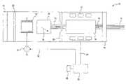
- FIG. 1is a side view of an example laser oscillator system that allows high frequency switching of an unpolarized beam
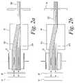
- FIG. 2Ais a side view of part of the laser oscillator system of FIG. 1 showing the beam paths proceeding from the amplifying medium to the second mirror in both on and off states;
- FIG. 2Bis a side view of part of the laser oscillator system of FIG. 1 showing the beam paths returning from the second mirror in the on state;
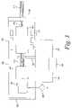
- FIG. 2Cis a side view of part of the laser oscillator system of FIG. 1 showing the beam paths returning from the second mirror in an off state;
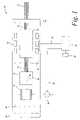
- FIG. 3is a side view of another example laser oscillator system that allows high frequency switching of an unpolarized beam.
- One example disclosedis a laser system having a source for producing input energy in response to an input drive signal.
- a laser gain mediumamplifies the beam energy.
- First and second mirrorsare disposed on opposing sides of the laser gain medium. The beam is reflected between the first and second mirrors. The first mirror is an output mirror for releasing a portion of the power circulating between the two mirrors.
- a birefringent beam displaceris disposed between the second mirror and the gain medium in the path of the circulating power. The displacer splits the incident unpolarized beam from the gain medium into two linearly polarized beams which are displaced laterally, but propagate in parallel. These two states of polarization are known as “e” and “o”. The e-polarized beam is displaced laterally and the o-polarized beam is unchanged.
- a Pockels cellis disposed between the displacer and the second mirror, intercepting both polarized beams.
- the Pockels cellis energized with a high voltage signal to alter the state of the polarized waves and deenergized to allow transmission of the waves without alteration.
- the second mirror of the systemis used to return the separated polarized beams along a path directly opposed to the input direction to the mirror. The beams then make a second, return, pass through the Pockels cell after which the state of polarization of the separated beams is either changed or unchanged, depending on the action of the Pockels cell.
- a control systemis coupled to the Pockels cell to switch between a first state allowing the release of the pulsed laser beam and a second state dispersing the output beam via the displacer preventing the release of the pulsed laser beam.
- FIG. 1illustrates a solid-state laser system 10 for producing a high-power pulsed output laser beam 11 .
- the laser system 10includes a pump source 12 that pumps a solid state laser medium 14 , which in the illustrated embodiment is in the form of a rod or a slab.
- the pump source 12is preferably one or more laser diode arrays although other sources, such as a flash lamp, may be used.
- Each laser diode arraytypically has several semiconductor laser diodes that convert electrical energy into optical energy that is absorbed in the laser medium 14 .
- the laser system 10includes two reflective surfaces such as a high reflective mirror 16 and an output coupling (OC) mirror 18 .
- a quarter wave plate 20 , a Pockels cell 22 and a beam displacer 24are disposed between the high reflective mirror 16 and the laser medium 14 .
- An aperture 26is disposed between the beam displacer 24 and the laser medium 14 .
- a high voltage source 28drives the Pockels cell 22 .
- the amount of absorption of energy by the laser medium 14 at a given wavelengthdepends on various factors such as the type of dopants provided in the laser medium 14 , the concentration of dopants, and the temperature at which the laser medium 14 is operated.
- the laser medium 14is made from Neodymium ( 3 +) doped, Yttrium-Aluminum Garnet (Nd:YAG)
- the peak absorptionoccurs at about 808 nm.
- the laser diodes at the pump source 12are made of gallium arsenide with aluminum doping (AlGaAs), they emit radiation at approximately 804 nm to 808 nm, which matches the maximum absorption spectrum for the Nd:YAG material of the laser medium 14 .
- an Nd:YAG laser mediumabsorbs energy at 808 nm, it then can release energy at a variety of wavelengths, the strongest of which is 1064 nm.
- These materials for the pump source 12 and the laser medium 14are used in one example of the solid state laser system 10 .
- the high-reflective (HR) mirror 16is typically mounted on a common mounting structure (e.g., optics bench assembly) with the laser medium 14 .
- the surface of the HR mirror 16typically has a reflectivity value of at least about 99% at the wavelength of the circulating beam 15 .
- the output coupling (OC) mirror 18is located on the opposite side of the laser medium 14 such that the circulating beam 15 resonates between the HR mirror 16 and the OC mirror 18 .
- the OC mirror 18has a partially reflective coating on its surface such that a predetermined amount of the circulating beam 15 is transmitted therethrough and released as the output laser beam 11 . The remaining energy is reflected back toward the laser medium 14 .
- the reflectivity of the OC mirror 18determines the overall output in the laser beam 11 . Also, the reflectivity must be enough to produce resonation through the laser medium 14 .
- the OC mirror 18can have a reflectivity that ranges from about 10% (high-gain system) to about 95% (low-gain system) with the optimum value being dependent on the amount of gain and loss in the circulating beam path. In one preferred embodiment, for the laser system 10 operating in a pulsed mode, the reflectivity of the OC mirror 18 is approximately 80%. Also, one of the mirrors 16 or 18 can be a coating placed on the end surface of the laser medium 14 .
- the quarter waveplate 20may be formed of crystal quartz or other birefringent material and serves to transform linearly polarized light into circularly polarized light. Upon retuning from mirror 16 the polarization state of the light is further changed from circular to linear with the plane of polarization 90 degrees from the plane of polarization of the input beam. In other embodiments, devices or objects other than the quarter waveplate 20 may be utilized to shift the polarization of the return beam, or waveplate 20 may be absent.
- the Pockels cell 22is disposed in the path of the circulating beam 15 from the laser medium 14 to the HR mirror 16 .
- the Pockels cell 22is an electro-optic crystal which when energized by a high voltage source 28 alters the polarization phase of the circulating beam 15 by a quarter wave (90 degrees) in the same way as the waveplate 20 .
- a quarter wave90 degrees
- other phase displacementsmay be made by the Pockels cell 22 .
- the beam displacer 24is a birefringent beam displacer which has sufficient dimensions to accommodate the circulating beam 15 .
- the beam displacer 24may be a beam displacer manufactured by, e.g., Conex, headquartered in Pleasanton, Calif., or Karl Lambrecht, headquartered in Chicago, I1.
- the birefringent beam displacer 24is formed of a birefringent material such as, e.g., yttrium vanadate, calcite, or rutile, each of which are synthetically developed optical materials with very high birefringence.
- the birefringent beam displacer 24may be coated with anti-reflection coating to minimize the amount of energy lost by the light beam while inside the birefringent beam displacer 24 .
- Birefringent materialshave optical properties such that the speed of light passing through them is dependent upon the direction of polarization. That is, the refractive index of birefringent materials is dependent upon the direction of the light beam's polarization.
- the beam displacer 24has an optic axis 30 which represents a certain direction or directions with respect to the crystal structure of the birefringent material.
- a light beam that has an electric field polarized completely perpendicular to the optic axis 30is called an ordinary wave, or o-wave.
- a light beam having an electric field that is in the plane of the optic axis and not perpendicular to it 30is called an extraordinary wave, or e-wave.
- An o-wave of a laser beampasses straight through the bifrefringent beam displacer 24 on a path parallel with the x-axis in FIG. 1 .
- the e-wave of the beamdoes not pass straight through the beam displacer 24 .
- the e-waveexperiences a walkoff such that when the e-wave exits the birefringent beam displacer 24 , it is no longer overlapping the o-wave.
- the length of the birefringent beam displacer 24is designed so that there is ideally no overlap between the o-wave and the e-wave, although in practical operation, small overlaps may be acceptable.
- the laser system 10also includes a Pockels cell power input 32 for supplying an input signal to the Pockels cell 22 and a pump-source power input 34 for supplying input power to the pump source 12 .
- the Pockels cell power input 32 and the pump-source power input 34include the drive electronics for operating the Pockels cell 22 and pump source 12 , respectively.
- the laser system 10includes a laser control system 36 that controls both the Pockels cell power input 32 and the pump-source power input 34 .
- the control system 36sends a drive input signal to the pump source 12 via the pump-source power input 34 .
- An input device 38allows the operator of the laser system 10 to enter information for determining the characteristics (e.g., power level, pulse width, frequency, etc.) of the laser beam 11 that exits the system 10 .
- the input device 38can be directly coupled to the laser control system 36 .
- the input device 38can communicate with the laser control system 36 from a remote location.
- FIGS. 2A-2Cshows the operation of the laser system 10 .
- the laser system 10is in either the “on” or “off” condition.
- the laser medium 14produces the circulating beam 15 that is reflected from the OC mirror 18 to form an intracavity beam 200 propagating toward the HR mirror 16 .
- the intracavity beam 200is split into an e-polarized wave 202 and an o-polarized wave 204 by the beam displacer 24 .
- the e-polarized wave 202is displaced by the walkoff angle of the displacer 24 while the o-polarized wave 204 passes directly through the displacer 24 .
- the e-polarized wave 202 and the o-polarized wave 204travel to the Pockels cell 22 .
- the waves 202 and 204then proceed to travel through the quarter waveplate 20 .
- the quarter waveplate 20changes the phase of the shifted waves 202 and 204 by 90 degrees.
- the phase shifted waves 202 and 204then are reflected off of the high reflective mirror 16 .
- the polarization state of the e- and o-wavesare phase shifted by the Pockels cell so that the beams are circularly polarized, but in opposite senses, the polarization of the beams 202 and 204 are then shifted by the quarter waveplate 20 so that they are returned to their original polarization state.
- the processis repeated after reflection from the HR mirror 16 so that when the beams are then shifted a final time by the Pockels cell 22 , they are transformed into linear polarization states which are the same as the input.
- the combination of the waveplate 20 and the energized Pockels cell 22results in a returned e-polarized wave 212 and a returned o-polarized wave 214 which are in the same polarization states as the original waves 202 and 204 .
- the e-polarized return wave 212is displaced at the walk off angle while the o-polarized wave 214 travels parallel to the x-axis of the beam displacer 24 .
- the e-polarized return wave 212 exits the wave displacer 24it overlaps the o-polarized return wave 214 to form a single unpolarized return beam 220 .
- the returned waves 212 and 214are thus combined by the beam displacer 24 and returned through the laser medium 14 ( FIG.
- the “on” conditionresults in a period of energy buildup from the excitation of the unpolarized beam 220 causing a pulsed output beam to be emitted from the OC mirror 16 when a threshold output energy is reached.
- FIG. 2Cshows the result of the original polarized waves 202 and 204 from FIG. 2A when the system 10 is in the “off” condition.
- high voltage input 28has been removed from the Pockels cell 22 via the Pockels cell control input 32 in FIG. 1 .
- the incoming polarized waves 202 and 204 in FIG. 2Ahave traveled through the Pockels cell 22 with no polarization change.
- the original polarized waves 202 and 204have been circularly polarized while passing through the quarter waveplate 20 .
- the waves 202 and 204are reflected back via the HR mirror 16 and pass through the quarter waveplate 20 again and are brought back to linear polarization, but in opposite states. This results in the original o-polarized wave 204 becoming a returned e-polarization wave 234 and the original e-polarized wave 202 becoming a returned o-polarized wave 232 .
- the returned o-polarized wave 232travels on a path through the Pockels cell 22 and through the displacer 24 parallel to the x-axis to impinge away from the aperture 26 .
- the returned e-polarized wave 202travels through the Pockels cell 22 and is displaced at the walkoff angle in the beam displacer 24 to impinge away from the aperture 26 .
- the circulating beam 15 from the laser medium 14 in FIG. 1does not fully transmit through the aperture 26 , but instead, a portion of the circulating beam 15 is diverted off axis to create a loss that is larger than the gain produced by the laser medium 14 . Thus, no laser beam 11 may exit from the laser system 10 .
- the laser system 10when the Pockels cell 22 is de-energized as shown in FIG. 2C , the laser system 10 is in the “off” condition and the lasing action produced by the laser medium 14 is suppressed.
- the Pockels cell 22is energized and the laser system 10 is in the “on” condition to allow for optical transmission as shown in FIGS. 2A-2B , the circulating beam 15 fully resonates between the two mirrors 16 and 18 such that a high-energy, short-duration pulse exits from the laser system 10 as the laser beam 11 .
- FIG. 3illustrates another laser oscillator system 300 which produces a pulsed output unpolarized beam 311 via a pump source 312 that pumps a solid state laser medium 314 .
- the laser oscillator system 300differs from the laser oscillator system 10 in FIG. 1 in the elimination of the quarter waveplate 20 .
- the laser system 300includes two reflective surfaces such as a high reflective mirror 316 and an output coupling (OC) mirror 318 .
- a Pockels cell 322 and a beam displacer 324are interposed between the high reflective mirror 316 and the laser medium 314 .
- An aperture 326is interposed between the beam displacer 324 and the laser medium 314 .
- a high voltage source 328drives the Pockels cell 322 .
- the Pockels cellis controlled via a control input 330 and the pump source 312 is controlled via an input 332 .
- the control inputs 320 and 332 and the pump input 312are coupled to a controller 334 .
- the components of the system 300 in FIG. 3operate identically to their counterparts in FIG. 1 .
- the system 300has an “on” condition where the high voltage source 328 is decoupled from the Pockels cell 322 .
- a circulating beam 315 from the laser medium 314is split into an o-polarized wave and an e-polarized wave by the beam displacer 324 . Since the Pockels cell 322 is de-energized, the polarized waves pass through the Pockels cell 322 and are reflected by the high reflective mirror 316 . The reflected waves do not shift in polarization and thus are recombined to the circulating beam 315 which travels through the aperture 326 to excite the laser medium 314 and increase the gain of the laser system 300 to produce an unpolarized laser pulse from the OC mirror 318 .
- the system 300is switched to an “off” state by energizing the Pockels cell 322 via the high voltage source 328 .
- the circulating beam 315is split into an o-polarized wave and an e-polarized wave by the beam displacer 324 as in the “on” condition.
- the Pockels cell 322is energized and transforms the polarization of the waves to circular polarization.
- the transformed wavesare reflected by the high reflective mirror 316 and pass through the Pockels cell 322 again.
- the Pockels cell 322further transforms the polarization of the waves from circular back to linear, but opposite in orientation from the input state.
- the controller 334adjusts the frequency of the laser pulse cycle via the control input 330 and the characteristics of the beam via the input 332 .
- the examples explained aboveprovide relatively faster switching from “off” to “on” states in comparison to a piezo-acoustic Q-switch for non-polarized lasers.
- the switching speeds for the above examplesare in the 20 ns range. This is a significant increase over the switching speed of 1000 ns for a piezo-acoustic Q-switch in a 5 mm diameter beam.
- Such examplesmay be employed in applications such as laser marking, or materials processing, cutting or welding.
Landscapes
- Physics & Mathematics (AREA)
- Electromagnetism (AREA)
- Engineering & Computer Science (AREA)
- Plasma & Fusion (AREA)
- Optics & Photonics (AREA)
- Lasers (AREA)
Abstract
Description
Claims (17)
Priority Applications (1)
| Application Number | Priority Date | Filing Date | Title |
|---|---|---|---|
| US11/540,461US7586958B2 (en) | 2006-09-29 | 2006-09-29 | Electro-opto switching of unpolarized lasers |
Applications Claiming Priority (1)
| Application Number | Priority Date | Filing Date | Title |
|---|---|---|---|
| US11/540,461US7586958B2 (en) | 2006-09-29 | 2006-09-29 | Electro-opto switching of unpolarized lasers |
Publications (2)
| Publication Number | Publication Date |
|---|---|
| US20080080569A1 US20080080569A1 (en) | 2008-04-03 |
| US7586958B2true US7586958B2 (en) | 2009-09-08 |
Family
ID=39261159
Family Applications (1)
| Application Number | Title | Priority Date | Filing Date |
|---|---|---|---|
| US11/540,461ActiveUS7586958B2 (en) | 2006-09-29 | 2006-09-29 | Electro-opto switching of unpolarized lasers |
Country Status (1)
| Country | Link |
|---|---|
| US (1) | US7586958B2 (en) |
Citations (64)
| Publication number | Priority date | Publication date | Assignee | Title |
|---|---|---|---|---|
| US3631361A (en) | 1968-07-22 | 1971-12-28 | Singer Co | Room temperature liquid laser |
| US3633126A (en) | 1969-04-17 | 1972-01-04 | Gen Electric | Multiple internal reflection face-pumped laser |
| US3740663A (en)* | 1970-12-21 | 1973-06-19 | Raytheon Co | Q-switched laser system |
| US3771031A (en) | 1973-03-05 | 1973-11-06 | Texas Instruments Inc | Header assembly for lasers |
| US3810041A (en) | 1971-06-14 | 1974-05-07 | Gen Electric | Face-pumped liquid laser device |
| US3820038A (en) | 1973-02-09 | 1974-06-25 | Atomic Energy Commission | Method and apparatus for producing isolated laser pulses having a fast rise time |
| US3986130A (en) | 1974-10-09 | 1976-10-12 | University Of Rochester | Laser apparatus |
| US4068190A (en)* | 1976-02-09 | 1978-01-10 | The United States Of America As Represented By The Secretary Of The Navy | Laser system having frequency doubling |
| US4084883A (en) | 1977-02-28 | 1978-04-18 | The University Of Rochester | Reflective polarization retarder and laser apparatus utilizing same |
| US4091274A (en) | 1976-12-22 | 1978-05-23 | United Technologies Corporation | Active laser mirror system |
| US4156209A (en) | 1977-05-16 | 1979-05-22 | Quanta-Ray, Inc. | Lens free of back focal points for use with high power light beams |
| US4225826A (en) | 1978-02-03 | 1980-09-30 | The University Of Rochester | Laser apparatus |
| US4228406A (en) | 1978-05-10 | 1980-10-14 | The University Of Rochester | Laser apparatus |
| US4233567A (en) | 1978-12-13 | 1980-11-11 | General Electric Company | Face-cooled laser device having increased energy storage and output |
| US4249141A (en) | 1978-06-08 | 1981-02-03 | University Of Rochester | Laser systems using pentaphosphate active mediums |
| US4468774A (en) | 1981-12-10 | 1984-08-28 | General Electric Company | Face pumped laser host mounting |
| US4507785A (en)* | 1981-04-08 | 1985-03-26 | The Commonwealth Of Australia | Unpolarized electro-optically Q-switched laser |
| US4575854A (en) | 1983-10-14 | 1986-03-11 | Mcdonnell Douglas Corporation | Uncooled YAG laser |
| US4710940A (en) | 1985-10-01 | 1987-12-01 | California Institute Of Technology | Method and apparatus for efficient operation of optically pumped laser |
| US4730324A (en) | 1986-10-02 | 1988-03-08 | General Electric Company | Method and apparatus for compensating for wave front distortion in a slab laser |
| US4731795A (en) | 1986-06-26 | 1988-03-15 | Amoco Corporation | Solid state laser |
| US4741354A (en) | 1987-04-06 | 1988-05-03 | Spire Corporation | Radial gas manifold |
| US4876694A (en) | 1986-07-07 | 1989-10-24 | Advanced Lasers Limited | External cavity slab lasers |
| US4896119A (en)* | 1984-06-07 | 1990-01-23 | The University Of Rochester | CW pumper CW pumped variable repetition rate regenerative laser amplifier system |
| US4949346A (en) | 1989-08-14 | 1990-08-14 | Allied-Signal Inc. | Conductively cooled, diode-pumped solid-state slab laser |
| US4972426A (en) | 1988-12-05 | 1990-11-20 | Asulab S.A. | Laser provided with an improved securing arrangement for its active medium |
| US5084888A (en) | 1989-12-29 | 1992-01-28 | Hoya Corporation | Laser medium for use in a composite slab type laser |
| US5084889A (en) | 1989-12-20 | 1992-01-28 | Hoya Corporation | Laser medium for use in a slab laser |
| US5138628A (en) | 1990-05-02 | 1992-08-11 | Thomson-Csf | Power laser with active mirror |
| US5148445A (en) | 1989-04-24 | 1992-09-15 | Quantronix Corp. | High power Nd:YLF solid state lasers |
| US5150371A (en) | 1991-06-05 | 1992-09-22 | Xerox Corporation | Laser diode carrier with a semiconductor cooler |
| US5156999A (en) | 1990-06-08 | 1992-10-20 | Wai-Hon Lee | Packaging method for semiconductor laser/detector devices |
| US5239549A (en) | 1990-09-27 | 1993-08-24 | Hoya Corporation | Composite slab laser medium and a laser employing the composite slab laser medium |
| US5253260A (en) | 1991-12-20 | 1993-10-12 | Hughes Aircraft Company | Apparatus and method for passive heat pipe cooling of solid state laser heads |
| US5287368A (en)* | 1992-04-21 | 1994-02-15 | Hughes Aircraft Company | High resolution spectral line selector |
| US5291504A (en) | 1992-02-18 | 1994-03-01 | Fibertek, Inc. | Laser pump module |
| US5394426A (en)* | 1992-11-13 | 1995-02-28 | Hughes Aircraft Company | Diode laser bar assembly |
| US5394427A (en) | 1994-04-29 | 1995-02-28 | Cutting Edge Optronics, Inc. | Housing for a slab laser pumped by a close-coupled light source |
| US5434875A (en) | 1994-08-24 | 1995-07-18 | Tamar Technology Co. | Low cost, high average power, high brightness solid state laser |
| US5521936A (en) | 1995-02-01 | 1996-05-28 | Paradigm Lasers, Inc. | Radial laser diode array |
| US5550853A (en) | 1994-12-21 | 1996-08-27 | Laser Physics, Inc. | Integral laser head and power supply |
| US5561684A (en) | 1994-12-29 | 1996-10-01 | Santa Fe Laser Co., Inc. | Laser diode pumped solid state laser construction |
| US5563899A (en) | 1988-08-30 | 1996-10-08 | Meissner; Helmuth E. | Composite solid state lasers of improved efficiency and beam quality |
| US5663980A (en) | 1995-05-22 | 1997-09-02 | Adachi; Yoshi | Semiconductor laser device having changeable wavelength, polarization mode, and beam shape image |
| US5663979A (en) | 1995-11-22 | 1997-09-02 | Light Solutions Corporation | Fiber stub end-pumped laser |
| US5734672A (en) | 1996-08-06 | 1998-03-31 | Cutting Edge Optronics, Inc. | Smart laser diode array assembly and operating method using same |
| US5740288A (en) | 1995-02-22 | 1998-04-14 | E-Tek Dynamics, Inc. | Variable polarization beam splitter, combiner and mixer |
| US5852622A (en) | 1988-08-30 | 1998-12-22 | Onyx Optics, Inc. | Solid state lasers with composite crystal or glass components |
| US5898211A (en) | 1996-04-30 | 1999-04-27 | Cutting Edge Optronics, Inc. | Laser diode package with heat sink |
| US5913108A (en) | 1998-04-30 | 1999-06-15 | Cutting Edge Optronics, Inc. | Laser diode packaging |
| US5936984A (en) | 1997-05-21 | 1999-08-10 | Onxy Optics, Inc. | Laser rods with undoped, flanged end-caps for end-pumped laser applications |
| US6014393A (en) | 1996-06-28 | 2000-01-11 | Commissariat A L'energie Atomique | Laser materials and microlasers having high active ion concentrations, and production processes |
| US6026109A (en) | 1998-01-22 | 2000-02-15 | Cutting Edge Optronics, Inc. | High-power, solid-state laser in a cylindrical package |
| US6061378A (en)* | 1997-05-13 | 2000-05-09 | Cutting Edge Optronics, Inc. | Multiple resonant cavity solid-state laser |
| US6094297A (en) | 1998-07-07 | 2000-07-25 | Trw Inc. | End pumped zig-zag slab laser gain medium |
| US6178040B1 (en) | 1998-06-25 | 2001-01-23 | Trw Inc. | Laser with two orthogonal zig-zag slab gain media for optical phase distortion compensation |
| US20020110164A1 (en) | 2001-02-13 | 2002-08-15 | Jan Vetrovec | High-average power active mirror solid-state laser with multiple subapertures |
| US20020118718A1 (en) | 2000-12-29 | 2002-08-29 | The Regents Of The University Of California | Parasitic oscillation suppression in solid state lasers using optical coatings |
| US6490299B1 (en) | 2000-07-20 | 2002-12-03 | Troitski | Method and laser system for generating laser radiation of specific temporal shape for production of high quality laser-induced damage images |
| US6711311B2 (en) | 2000-04-20 | 2004-03-23 | Jds Uniphase Inc. | Polarization beam splitter or combiner |
| US6744803B2 (en) | 2002-01-17 | 2004-06-01 | Northrop Grumman Corporation | High brightness laser oscillator with spherical aberration |
| US6765722B2 (en) | 2000-12-15 | 2004-07-20 | Dicon Fiberoptics, Inc. | Polarization beam combiner for fiber optic applications |
| US6822994B2 (en) | 2001-06-07 | 2004-11-23 | Northrop Grumman Corporation | Solid-state laser using ytterbium-YAG composite medium |
| US20050267345A1 (en)* | 2001-07-02 | 2005-12-01 | The University Of Texas System, Board Of Regents | Applications of light-emitting nanoparticles |
- 2006
- 2006-09-29USUS11/540,461patent/US7586958B2/enactiveActive
Patent Citations (65)
| Publication number | Priority date | Publication date | Assignee | Title |
|---|---|---|---|---|
| US3631361A (en) | 1968-07-22 | 1971-12-28 | Singer Co | Room temperature liquid laser |
| US3633126A (en) | 1969-04-17 | 1972-01-04 | Gen Electric | Multiple internal reflection face-pumped laser |
| US3740663A (en)* | 1970-12-21 | 1973-06-19 | Raytheon Co | Q-switched laser system |
| US3810041A (en) | 1971-06-14 | 1974-05-07 | Gen Electric | Face-pumped liquid laser device |
| US3820038A (en) | 1973-02-09 | 1974-06-25 | Atomic Energy Commission | Method and apparatus for producing isolated laser pulses having a fast rise time |
| US3771031A (en) | 1973-03-05 | 1973-11-06 | Texas Instruments Inc | Header assembly for lasers |
| US3986130A (en) | 1974-10-09 | 1976-10-12 | University Of Rochester | Laser apparatus |
| US4068190A (en)* | 1976-02-09 | 1978-01-10 | The United States Of America As Represented By The Secretary Of The Navy | Laser system having frequency doubling |
| US4091274A (en) | 1976-12-22 | 1978-05-23 | United Technologies Corporation | Active laser mirror system |
| US4084883A (en) | 1977-02-28 | 1978-04-18 | The University Of Rochester | Reflective polarization retarder and laser apparatus utilizing same |
| US4156209A (en) | 1977-05-16 | 1979-05-22 | Quanta-Ray, Inc. | Lens free of back focal points for use with high power light beams |
| US4225826A (en) | 1978-02-03 | 1980-09-30 | The University Of Rochester | Laser apparatus |
| US4228406A (en) | 1978-05-10 | 1980-10-14 | The University Of Rochester | Laser apparatus |
| US4249141A (en) | 1978-06-08 | 1981-02-03 | University Of Rochester | Laser systems using pentaphosphate active mediums |
| US4233567A (en) | 1978-12-13 | 1980-11-11 | General Electric Company | Face-cooled laser device having increased energy storage and output |
| US4507785A (en)* | 1981-04-08 | 1985-03-26 | The Commonwealth Of Australia | Unpolarized electro-optically Q-switched laser |
| US4468774A (en) | 1981-12-10 | 1984-08-28 | General Electric Company | Face pumped laser host mounting |
| US4575854A (en) | 1983-10-14 | 1986-03-11 | Mcdonnell Douglas Corporation | Uncooled YAG laser |
| US4896119A (en)* | 1984-06-07 | 1990-01-23 | The University Of Rochester | CW pumper CW pumped variable repetition rate regenerative laser amplifier system |
| US4710940A (en) | 1985-10-01 | 1987-12-01 | California Institute Of Technology | Method and apparatus for efficient operation of optically pumped laser |
| US4731795A (en) | 1986-06-26 | 1988-03-15 | Amoco Corporation | Solid state laser |
| US4876694A (en) | 1986-07-07 | 1989-10-24 | Advanced Lasers Limited | External cavity slab lasers |
| US4730324A (en) | 1986-10-02 | 1988-03-08 | General Electric Company | Method and apparatus for compensating for wave front distortion in a slab laser |
| US4741354A (en) | 1987-04-06 | 1988-05-03 | Spire Corporation | Radial gas manifold |
| US5563899A (en) | 1988-08-30 | 1996-10-08 | Meissner; Helmuth E. | Composite solid state lasers of improved efficiency and beam quality |
| US5852622A (en) | 1988-08-30 | 1998-12-22 | Onyx Optics, Inc. | Solid state lasers with composite crystal or glass components |
| US4972426A (en) | 1988-12-05 | 1990-11-20 | Asulab S.A. | Laser provided with an improved securing arrangement for its active medium |
| US5148445A (en) | 1989-04-24 | 1992-09-15 | Quantronix Corp. | High power Nd:YLF solid state lasers |
| US4949346A (en) | 1989-08-14 | 1990-08-14 | Allied-Signal Inc. | Conductively cooled, diode-pumped solid-state slab laser |
| US5084889A (en) | 1989-12-20 | 1992-01-28 | Hoya Corporation | Laser medium for use in a slab laser |
| US5084888A (en) | 1989-12-29 | 1992-01-28 | Hoya Corporation | Laser medium for use in a composite slab type laser |
| US5138628A (en) | 1990-05-02 | 1992-08-11 | Thomson-Csf | Power laser with active mirror |
| US5156999A (en) | 1990-06-08 | 1992-10-20 | Wai-Hon Lee | Packaging method for semiconductor laser/detector devices |
| US5239549A (en) | 1990-09-27 | 1993-08-24 | Hoya Corporation | Composite slab laser medium and a laser employing the composite slab laser medium |
| US5150371A (en) | 1991-06-05 | 1992-09-22 | Xerox Corporation | Laser diode carrier with a semiconductor cooler |
| US5253260A (en) | 1991-12-20 | 1993-10-12 | Hughes Aircraft Company | Apparatus and method for passive heat pipe cooling of solid state laser heads |
| US5291504A (en) | 1992-02-18 | 1994-03-01 | Fibertek, Inc. | Laser pump module |
| US5287368A (en)* | 1992-04-21 | 1994-02-15 | Hughes Aircraft Company | High resolution spectral line selector |
| US5394426A (en)* | 1992-11-13 | 1995-02-28 | Hughes Aircraft Company | Diode laser bar assembly |
| US5394427A (en) | 1994-04-29 | 1995-02-28 | Cutting Edge Optronics, Inc. | Housing for a slab laser pumped by a close-coupled light source |
| US5434875A (en) | 1994-08-24 | 1995-07-18 | Tamar Technology Co. | Low cost, high average power, high brightness solid state laser |
| US5550853A (en) | 1994-12-21 | 1996-08-27 | Laser Physics, Inc. | Integral laser head and power supply |
| US5561684A (en) | 1994-12-29 | 1996-10-01 | Santa Fe Laser Co., Inc. | Laser diode pumped solid state laser construction |
| US5521936A (en) | 1995-02-01 | 1996-05-28 | Paradigm Lasers, Inc. | Radial laser diode array |
| US5740288A (en) | 1995-02-22 | 1998-04-14 | E-Tek Dynamics, Inc. | Variable polarization beam splitter, combiner and mixer |
| US5663980A (en) | 1995-05-22 | 1997-09-02 | Adachi; Yoshi | Semiconductor laser device having changeable wavelength, polarization mode, and beam shape image |
| US5663979A (en) | 1995-11-22 | 1997-09-02 | Light Solutions Corporation | Fiber stub end-pumped laser |
| US5898211A (en) | 1996-04-30 | 1999-04-27 | Cutting Edge Optronics, Inc. | Laser diode package with heat sink |
| US5985684A (en) | 1996-04-30 | 1999-11-16 | Cutting Edge Optronics, Inc. | Process for manufacturing a laser diode having a heat sink |
| US6014393A (en) | 1996-06-28 | 2000-01-11 | Commissariat A L'energie Atomique | Laser materials and microlasers having high active ion concentrations, and production processes |
| US5734672A (en) | 1996-08-06 | 1998-03-31 | Cutting Edge Optronics, Inc. | Smart laser diode array assembly and operating method using same |
| US6061378A (en)* | 1997-05-13 | 2000-05-09 | Cutting Edge Optronics, Inc. | Multiple resonant cavity solid-state laser |
| US5936984A (en) | 1997-05-21 | 1999-08-10 | Onxy Optics, Inc. | Laser rods with undoped, flanged end-caps for end-pumped laser applications |
| US6026109A (en) | 1998-01-22 | 2000-02-15 | Cutting Edge Optronics, Inc. | High-power, solid-state laser in a cylindrical package |
| US5913108A (en) | 1998-04-30 | 1999-06-15 | Cutting Edge Optronics, Inc. | Laser diode packaging |
| US6178040B1 (en) | 1998-06-25 | 2001-01-23 | Trw Inc. | Laser with two orthogonal zig-zag slab gain media for optical phase distortion compensation |
| US6094297A (en) | 1998-07-07 | 2000-07-25 | Trw Inc. | End pumped zig-zag slab laser gain medium |
| US6711311B2 (en) | 2000-04-20 | 2004-03-23 | Jds Uniphase Inc. | Polarization beam splitter or combiner |
| US6490299B1 (en) | 2000-07-20 | 2002-12-03 | Troitski | Method and laser system for generating laser radiation of specific temporal shape for production of high quality laser-induced damage images |
| US6765722B2 (en) | 2000-12-15 | 2004-07-20 | Dicon Fiberoptics, Inc. | Polarization beam combiner for fiber optic applications |
| US20020118718A1 (en) | 2000-12-29 | 2002-08-29 | The Regents Of The University Of California | Parasitic oscillation suppression in solid state lasers using optical coatings |
| US20020110164A1 (en) | 2001-02-13 | 2002-08-15 | Jan Vetrovec | High-average power active mirror solid-state laser with multiple subapertures |
| US6822994B2 (en) | 2001-06-07 | 2004-11-23 | Northrop Grumman Corporation | Solid-state laser using ytterbium-YAG composite medium |
| US20050267345A1 (en)* | 2001-07-02 | 2005-12-01 | The University Of Texas System, Board Of Regents | Applications of light-emitting nanoparticles |
| US6744803B2 (en) | 2002-01-17 | 2004-06-01 | Northrop Grumman Corporation | High brightness laser oscillator with spherical aberration |
Also Published As
| Publication number | Publication date |
|---|---|
| US20080080569A1 (en) | 2008-04-03 |
Similar Documents
| Publication | Publication Date | Title |
|---|---|---|
| EP0783783B1 (en) | Passively stabilized intracavity doubling laser | |
| US4872177A (en) | Laser diode pumped solid state laser | |
| US4701929A (en) | Laser diode pumped solid state laser | |
| US4756003A (en) | Laser diode pumped solid state laser | |
| US9160136B1 (en) | External diffusion amplifier | |
| US5359622A (en) | Radial polarization laser resonator | |
| US20110150013A1 (en) | Resonant pumping of thin-disk laser with an optically pumped external-cavity surface-emitting semiconductor laser | |
| WO2003073564A2 (en) | Laser cavity pumping method and laser system thereof | |
| KR102235631B1 (en) | Laser Equipment for Outputting Multi-Pulse Width | |
| JP3939928B2 (en) | Wavelength converter | |
| IL172951A (en) | Slab laser and method with improved and directionally homogenized beam quality | |
| JP5467629B2 (en) | Photonic fiber trigger laser equipment | |
| US5856996A (en) | Compact efficient solid state laser | |
| JP4231829B2 (en) | Internal cavity sum frequency mixing laser | |
| US10868402B2 (en) | Passively Q-switched solid-state laser with compressed pulse duration | |
| Agnesi et al. | High-peak-power diode-pumped passively Q-switched Nd: YVO4 laser | |
| JP4407039B2 (en) | Solid-state laser device and solid-state laser device system | |
| US7460566B2 (en) | Laser power reduction without mode change | |
| US20050276300A1 (en) | Laser device using two laser media | |
| JP3539030B2 (en) | Laser light generator | |
| US6553052B1 (en) | Solid-state laser | |
| US20050036531A1 (en) | Laser device | |
| US7586958B2 (en) | Electro-opto switching of unpolarized lasers | |
| JPH0786668A (en) | Semiconductor laser pumped solid state laser device | |
| KR101596478B1 (en) | Multi-pulse width as the laser output of laser equipment |
Legal Events
| Date | Code | Title | Description |
|---|---|---|---|
| AS | Assignment | Owner name:NORTHROP GRUMMAN CORPORATION, CALIFORNIA Free format text:ASSIGNMENT OF ASSIGNORS INTEREST;ASSIGNOR:KENNEDY, CHANDLER JAMES;REEL/FRAME:018372/0477 Effective date:20060928 | |
| FEPP | Fee payment procedure | Free format text:PAYOR NUMBER ASSIGNED (ORIGINAL EVENT CODE: ASPN); ENTITY STATUS OF PATENT OWNER: LARGE ENTITY | |
| STCF | Information on status: patent grant | Free format text:PATENTED CASE | |
| AS | Assignment | Owner name:NORTHROP GRUMMAN SPACE & MISSION SYSTEMS CORP.,CAL Free format text:ASSIGNMENT OF ASSIGNORS INTEREST;ASSIGNOR:NORTHROP GRUMMAN CORPORTION;REEL/FRAME:023699/0551 Effective date:20091125 Owner name:NORTHROP GRUMMAN SPACE & MISSION SYSTEMS CORP., CA Free format text:ASSIGNMENT OF ASSIGNORS INTEREST;ASSIGNOR:NORTHROP GRUMMAN CORPORTION;REEL/FRAME:023699/0551 Effective date:20091125 | |
| AS | Assignment | Owner name:NORTHROP GRUMMAN SYSTEMS CORPORATION,CALIFORNIA Free format text:ASSIGNMENT OF ASSIGNORS INTEREST;ASSIGNOR:NORTHROP GRUMMAN SPACE & MISSION SYSTEMS CORP.;REEL/FRAME:023915/0446 Effective date:20091210 Owner name:NORTHROP GRUMMAN SYSTEMS CORPORATION, CALIFORNIA Free format text:ASSIGNMENT OF ASSIGNORS INTEREST;ASSIGNOR:NORTHROP GRUMMAN SPACE & MISSION SYSTEMS CORP.;REEL/FRAME:023915/0446 Effective date:20091210 | |
| FPAY | Fee payment | Year of fee payment:4 | |
| FPAY | Fee payment | Year of fee payment:8 | |
| MAFP | Maintenance fee payment | Free format text:PAYMENT OF MAINTENANCE FEE, 12TH YEAR, LARGE ENTITY (ORIGINAL EVENT CODE: M1553); ENTITY STATUS OF PATENT OWNER: LARGE ENTITY Year of fee payment:12 |