US7586884B2 - Joint packet detection in wireless communication system with one or more receiver - Google Patents
Joint packet detection in wireless communication system with one or more receiverDownload PDFInfo
- Publication number
- US7586884B2 US7586884B2US10/642,070US64207003AUS7586884B2US 7586884 B2US7586884 B2US 7586884B2US 64207003 AUS64207003 AUS 64207003AUS 7586884 B2US7586884 B2US 7586884B2
- Authority
- US
- United States
- Prior art keywords
- packet
- detector
- format
- detection
- antennas
- Prior art date
- Legal status (The legal status is an assumption and is not a legal conclusion. Google has not performed a legal analysis and makes no representation as to the accuracy of the status listed.)
- Active, expires
Links
- 238000001514detection methodMethods0.000titleclaimsabstractdescription83
- 238000004891communicationMethods0.000titledescription9
- 238000005070samplingMethods0.000claimsdescription13
- 230000002452interceptive effectEffects0.000claimsdescription3
- 238000000034methodMethods0.000abstractdescription16
- 230000008569processEffects0.000abstractdescription13
- 239000000523sampleSubstances0.000description27
- 238000012545processingMethods0.000description20
- 238000010586diagramMethods0.000description11
- 239000012723sample bufferSubstances0.000description6
- 230000000875corresponding effectEffects0.000description5
- 230000000694effectsEffects0.000description5
- 238000009825accumulationMethods0.000description3
- 230000005540biological transmissionEffects0.000description3
- 230000002596correlated effectEffects0.000description3
- 230000003111delayed effectEffects0.000description3
- 238000001914filtrationMethods0.000description3
- 238000012549trainingMethods0.000description3
- 238000007792additionMethods0.000description2
- 239000000654additiveSubstances0.000description2
- 230000000996additive effectEffects0.000description2
- 238000013459approachMethods0.000description2
- 230000008901benefitEffects0.000description2
- 230000008878couplingEffects0.000description2
- 238000010168coupling processMethods0.000description2
- 238000005859coupling reactionMethods0.000description2
- 125000004122cyclic groupChemical group0.000description2
- 230000010363phase shiftEffects0.000description2
- 206010011878DeafnessDiseases0.000description1
- 238000012952ResamplingMethods0.000description1
- 230000015556catabolic processEffects0.000description1
- 230000008859changeEffects0.000description1
- 230000003247decreasing effectEffects0.000description1
- 238000006731degradation reactionMethods0.000description1
- 238000013461designMethods0.000description1
- 238000011161developmentMethods0.000description1
- 230000018109developmental processEffects0.000description1
- 238000005562fadingMethods0.000description1
- 238000010606normalizationMethods0.000description1
- 238000012552reviewMethods0.000description1
- 230000035945sensitivityEffects0.000description1
- 230000011664signalingEffects0.000description1
- 239000007787solidSubstances0.000description1
- 238000001228spectrumMethods0.000description1
- 230000007704transitionEffects0.000description1
Images


Classifications
- H—ELECTRICITY
- H04—ELECTRIC COMMUNICATION TECHNIQUE
- H04B—TRANSMISSION
- H04B17/00—Monitoring; Testing
- H04B17/30—Monitoring; Testing of propagation channels
- H04B17/309—Measuring or estimating channel quality parameters
- H04B17/318—Received signal strength
Definitions
- Wireless networkshave become increasingly popular, as computers and other devices can be coupled for data communications without requiring wired connections between the network nodes.
- One set of standards for wireless networksis the IEEE 802.11 standards, but other wireless standards or protocols might be used instead.
- IEEE 802.11 standardsthere are at least two widely-used standards, 802.11a and 802.11b, and communication systems and devices might be required to support both standards and/or be required to operate in areas where both are being used.
- a receiverPrior to decoding bits having information content provided by a transmitter, a receiver typically senses a packet being transmitted and then performs steps to characterize the channel, synchronize with the transmitted packet, and the like. Packet detection is a process of determining that a packet is present on the channel (i.e., it is being, or has been, transmitted by a transmitter), determining the type of packet it is (at least to the extent needed to perform further processing on the packet or its contents) and to activate receiver components as needed to handle further processing.
- the receive logicis implemented in digital signal processing (DSP) commands provided to a DSP processor.
- DSPdigital signal processing
- the receivercan be configured to remove or lower the power to such hardwired circuitry until a packet detector indicates that the received signal contains a packet to be further processed. In either case, processing power and/or computing effort is preserved when no packets are detected. This saves power and/or processing requirements, which are often constrained in wireless receivers, but requires packet detection. So that portions of the packet are not lost, the receiver should detect and existence of a packet and take any actions needed to start packet processing before essential elements of the packet are missed. Therefore, packet detection should be efficient and quick.
- an 802.11 receiverIn addition to the problem of possibly overlapping 802.11 signals, an 802.11 receiver must also deal with narrowband non-802.11 signals, such as Bluetooth, scientific equipment, medical equipment or microwave ovens, and the receiver's packet detector should preferably not cause false triggers on such interference. Aside from the interference issues and packet detection issues, a receiver that must receive and process both 802.11a and 802.11b signals cannot use a simple common sampling scheme, as conventional 802.11a receivers operate at a 20 MHz sampling rate, while conventional 802.11b receivers operate at a sampling rate of 22 MHz.
- a typical node in a wireless networkincludes a receive chain and a transmit chain and each chain uses only one antenna at a time.
- MIMOmultiple input, multiple output
- MIMO communication systemsare known in the art. Such systems generally include a transmitter having a number (M t ) of transmit antennas communicating with a receiver having a number (M r ) of receive antennas, where M r and M t may or may not be equal.
- M ta number of transmit antennas
- M ra number of receive antennas
- M r and M tmay or may not be equal.
- bits of data to be transmittedare grouped and each group of bits is mapped to a symbol (a particular combination of phase and amplitude) in a signaling constellation.
- a number of constellationsare known in the art, including binary phase-shift keying (BPSK), quadrature phase-shift keying (QPSK), and quadrature amplitude modulation (QAM) constellations.
- BPSKbinary phase-shift keying
- QPSKquadrature phase-shift keying
- QAMquadrature amplitude modulation
- each of the M t transmit antennatransmits, at substantially the same time, a symbol representing a different group of bits.
- each symbolrepresents B bits
- the number of bits transmitted per channel “period”is B*M t .
- Each receive antennareceives a signal that is a combination of signals from the transmit antennas, modified by channel properties (e.g., fading and delay) and noise.
- the receiverdecodes (i.e., reconstructs) the M t transmitted signals from the M r received signals using its knowledge of the possible transmitted symbols and the properties of the communication channel. Because of the improved reception abilities of multiple antenna systems, they are often expected to receive signals with lower signal-to-noise ratios (SNR) than other systems. With a wider expected operating range in terms of SNR, correct packet detection is expected at lower SNRs, making many conventional packet detection schemes unsuitable.
- SNRsignal-to-noise ratios
- a packet detectorjointly detects 802.11a packets, 802.11b packets and interference that is within a monitored frequency range but is not formatted as 802.11a packets or 802.11b packets.
- the packet detectorcan use signals from one or more antennas. Detection of signals is done using differentially detected correlations. In addition to packet detection, the packet detector can identify signal levels, noise levels and locations of narrowband interference. The process of packet detection and identifying other indicators can be done simultaneously and as the signal is being received.
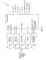
- FIG. 1is a block diagram of a simple wireless network that might use the present invention.
- FIG. 2is a block diagram illustrating the coupling between one device and one network connection of the wireless network shown in FIG. 1 .
- FIG. 3is a block diagram of a receive section of node hardware as might be used in hardware illustrated in FIG. 2 .
- FIG. 4is a block diagram of portions of a receiver including packet detection elements as might be used in the receive section of FIG. 3 .
- FIG. 5is a block diagram of an 802.11b packet detector as might be used in the receiver of FIG. 4 .
- FIG. 6graphically illustrates correlation sampling.
- FIG. 7is a block diagram of an 802.11a packet detector as might be used in the receiver of FIG. 4 .
- FIG. 8is a block diagram of a continuous wave (CW) detector as might be used in the receiver of FIG. 4 .
- CWcontinuous wave
- FIG. 9is a block diagram (comprising 9 A, 9 B, 9 C) of an interference detector as might be used in the receiver of FIG. 4 .
- FIG. 10is a set of plots showing performance of one embodiment of a packet detector described above;
- FIG. 10Ashows 802.11a detection curves,
- FIG. 10Bshows 802.11b detection curves and
- FIG. 10Cshows CW interference detection curves.
- FIG. 1illustrates a simple wireless network that might use the present invention.
- a wireless network 10comprises a plurality of nodes 12 wherein each node 12 is capable of communicating with at least one other node 12 of wireless network 10 .
- wireless network 10is a local area wireless network, as might be used within a building, campus, vehicle or similar environments.
- wireless network 10is designed to be compliant with one or more of the IEEE 802.11 standards.
- IEEE 802.11g standardcontemplates different signals than the 802.11a or 802.11b standards and the 802.11 set of standards might be further modified for later developments.
- the teachings of this disclosurecan be used for a system where two other protocol standards are used, with or without the unwanted interference.
- at least one of the protocolsis an extended 802.11a protocol usable between devices that support the protocol.
- FIG. 1is intended to be a simplified and generalized diagram of a wireless network. Interfering signal generators are not shown, but are assumed to be present.
- node devices 14include laptops, personal digital assistants (PDAs), or any other portable or semi-portable electronic device needing to communicate with other devices, or a stationary electronic device needing to communicate with other devices where a wire connection to a network or the other devices is not available or easily provided.
- Wired network interfaces 16couple their respective nodes to a network. Examples of such networks include the Internet, a local area network (LAN) or a public or private connection to a TCP/IP packet network or other packet network or networks.
- a plurality of node devicesare outfitted with circuitry and/or software that implements a node 12 functionality and one or more network access points are provided in wireless network 10 to provide access between such a node device and the network to which a wired network interface is coupled.
- a node coupled to a node deviceis referred to as a “station” and a node coupled to a wired network interface is referred to as an “access point”.
- an access pointJust one example of the uses of such a system is to connect computers within a building to a network without requiring network wires to be run to each computer.
- the buildingwould be outfitted with stationary access points coupled to the network which are within wireless communication range of wireless network cards in each of the stations coupled to the network.
- FIG. 2shows in more detail the coupling between one device and one network connection.
- node device 14is coupled to a device I/O section of node hardware 20 .
- Node hardware 20includes a transmit section and a receive section, each coupled to the device I/O section.
- the transmit sectiontransmits a signal through a wireless channel 21 to a receive section of access point hardware 22 .
- That receive sectionis coupled to a network I/O section, thus providing a data communication path from device 14 to a network 28 .
- a path from network 28 to device 14is also provided via the network I/O section of access point hardware 22 , a transmit section of access point hardware 22 , a receive section of node hardware 20 and the device I/O section of node 20 .
- the characteristics of wireless channel 21depend on many factors, such as the location of node hardware 20 and access point hardware 22 as well as intervening objects, such as walls, buildings and natural obstructions, as well as influences by other devices and transmitters and receivers and signal-reflecting surfaces.
- node hardware 20can be integrated in with device 14 .
- node hardware 20might be an add-on PCMCIA card that is inserted into the laptop's PCMCIA slot.
- access point hardware 22is implemented as part of a wired network interface device that is just used to couple a wired network to a wireless network. Notwithstanding the typical implementation, it should be understood that nothing here prevents the diagram of FIG. 2 from being entirely symmetrical, i.e., wherein node hardware 20 and access point hardware 22 are nearly identical instances of hardware devices.
- FIG. 3illustrates components of a receive section 30 .
- Receive section 30receives one or more signals over the wireless channel via antennas 32 , which are initially processed by RF section 34 .
- RF section 34might, for example, process the signals to form baseband signals to form digital signal streams.
- receive section 30also might include FIR(s) 35 and various subsections 40 , 42 , 44 for processing 802.11a, 802.11b and 802.11 extended signals, respectively.
- Receive section 30also includes a joint packet detector 37 described in more detail below. Further details of elements of receive section 30 not more fully described herein are shown in U.S. patent application Ser. No. 10/068,360, filed on Feb. 5, 2002 and entitled “Multi-Antenna Wireless Receiver Chain With Vector Decoding”, which is incorporated by reference herein for all purposes. It should be understood that the present invention is not limited to the particular receiver implementations shown here or there.
- Joint packet detector 37processes input signals to determine the beginning of a packet and may provide a packet detector signal to other elements, such as subsections 40 , 42 , 44 , to indicate whether any further processing is needed at all. Where receive section 30 is implemented as instructions for a digital signal processor, joint packet detector 37 might be code that determines whether or not a packet is detected and then sets a flag that the processor uses to determine whether to execute code for the other blocks shown. FIG. 3 shows multiple detect signals being provided, possibly along with other signals (“ancillary signals” used by other elements as well as joint packet detector 37 and “pass-through signals” generated but not used directly by joint packet detector 37 ) derived from some of the same processing.
- ancillary signalsused by other elements as well as joint packet detector 37 and “pass-through signals” generated but not used directly by joint packet detector 37
- joint packet detector 37can operate at a common sampling rate, such as 20 MHz, even when that sample rate is not the “native” sample rate for the protocol in which packets are being detected. This allows for a more efficient joint packet detector.
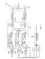
- FIG. 4illustrates joint packet detector 37 in greater detail.
- I and Q inputs from one or more receive antennasare inputs to several detection blocks comprising 802.11b detector 102 , 802.11a detector 104 , CW detector 106 , power level detector 108 and interference locator 110 , each of which are described below in greater detail.
- the outputs of the detection blocksare provided to a controller 120 that provides outputs for use by the receiver.
- controller 120provides outputs for use by the receiver.
- some of the functions described here as being done by controller 120might instead be performed by the individual blocks.
- additional detectorsare provided for other subsections, such as an 802.11 extended subsection.
- the outputs of the blocks that are inputs to controller 120are as shown in Table 1.
- the outputs of controller 120are as shown in Table 2.
- the coarse estimate for transmitter/receiver frequency offsetcould be calculated elsewhere, but when calculated in interference locator 110 , any narrowband interference can be easily removed from the signal prior to determination of a frequency offset with much less sensitivity to narrowband interference.
- the narrowband interferenceis “removed” by filtering out the subcarriers surrounding detected narrowband interference.
- the cw_present and pwr signalsmight be used by controller 120 as an indication of the presence of a strong narrowband interferer, in which case any 802.11a or 802.11b packet detection determinations are ignored as most likely being false alarms.
- controller 120appears dedicated to the detection blocks in FIG. 4 , controller 120 might be so dedicated or it might handle other functionality that controls other, unshown, functions or processes. Some functions of controller 120 are described below with reference to the blocks that generate inputs to controller 120 . For example, the “detect_ 11 a ” signal is described below in the description of how the 802.11a metrics are generated. The passthrough signals are used by other blocks, such as 802.11a or 802.11b subsections and need not be used by controller 120 itself.
- signals that are indicatorsmight be binary signals, but in other implementations, the signals can be multilevel, indicating a probability, confidence or certainty value (e.g. degree of certainty) associated about what has been indicated. For example detect_ 11 a might have a signal value that indicates a 70% probability that an 802.11a packet is being received. In the end, however, a binary decision needs to be made as to whether or not to start the 802.11a/b subsections, so the indicators would be expected to ultimately reduce to binary signals.
- the preamble of an 802.11b packetcomprises sync bits that do not contain data.
- the preamble portion of the signalis used to detect the presence of the packet and then to estimate signal and channel parameters.
- FIG. 5illustrates one implementation of 802.11b packet detector 102 .
- packet detectionis done by correlating inputs and checking the resulting correlation.
- Detector 102can provide a pair of metrics, c 11 b (correlation metric for 802.11b) and p 11 b (power metric for 802.11b), for use by controller 120 in formulating detect_ 11 b or detector 102 might provide a single metric that is a function of c 11 b and p 11 b , such as p 11 b /c 11 b or other variations.
- a packetmight be deemed detected when Equation 1 is true for some threshold, T_ 11 b .
- Equation 2If the number of symbols over which c 11 b is generated is different than the number of symbols over which p 11 b is generated, those values might be taken into account, as illustrated by Equation 2.
- Equation 2normalizes c 11 b by NSYM ⁇ 1, wherein NSYM is a fixed constant indicating a maximum number of symbols (a symbol being 20 samples, which is one Barker code) used for calculations, and normalizes p 11 b by nsym, where nsym is equal to the lesser of NSYM and the number of symbols that have been received since the last reset of the detector.
- the number of addends used for calculating p 11 bis the same as the number of symbols, instead of being one less than the number of symbols, so p 11 b is normalized using nsym to get the average power per symbol.
- the input signals from N receive antennasare used.
- signalscan be complex signals and operations such as addition and multiplication can be complex operations.
- the input signalsrun through Barker correlators 302 , one per antenna.
- One advantage of the approach described hereis that where an incoming signal is processed to detect packets, much of the processing can be duplicated since the signal is sampled at a common sampling rate. We have determined that sufficient accuracy can be had detecting 802.11b packets even with a sampling rate of 20 MHz. Of course, once a packet is detected and it is found to be an 802.11b packet, the sampling rate might be changed to 22 MHz to operate at the natural 802.11b sampling rate.
- sampling processesmight work in other situations, such as sampling at 22 MHz for both detections, sampling at a multiple of, or an even fraction of, 20 MHz or 22 MHz, or even at a rate that is not a multiple or even fraction of 20 MHz or 22 MHz.
- Barker correlators 302operate at a sample rate of 20 MHz, even though 802.11b signals are generated at 22 MHz.
- the 20-tap Barker codeis a resampling of the 11-tap Barker code.
- a 20-tap resampled and quantized sequencemight be
- the whole packet detectorcan operate at a 20 MHz sample rate and some of the processing done on the inputs for 802.11a detection can be used as well for 802.11b detection and for generating ancillary and/or passthrough signals.
- the outputs of the Barker correlatorsare represented by R bi (k). Note that other modified Barker sequences might be used instead of the one described above.
- each Barker correlator 302is processed to determine two differential correlations, DC b1 (n) and DC b2 (n). As shown in Equations 3-4, the outputs of Barker correlators 302 are differentially correlated, in that the correlation output is multiplied by a delayed and conjugated correlation output. The differential correlation is done by correlation block 304 .
- correlation block 304comprises delay lines 306 , conjugators 308 and multipliers 309 (one per antenna) as well as an adder 310 and two accumulators 312 (one per differential correlation.
- the inputs to adder 310are the Barker correlator outputs from each of the antennas, each multiplied by a version of itself, delayed and conjugated.
- the output of adder 310labelled “C(k)” in FIG. 5 , is provided to accumulators 312 which, in this example, accumulate twelve values for C(k).
- the number of values accumulatedmight be larger than twelve, but at the cost of a decreased SNR performance. Smaller numbers of values will give significant SNR degradation.
- FIG. 6showing a real portion of an example of the correlation output.
- the signalwould likely be a complex signal with an arbitrary unknown phase offset and frequency drift, but to keep the example simple, only the real portion is shown.
- the differential correlationprovides two outputs, one comprising the correlation of the interval A, and one comprising the correlation of the interval B.
- the differential correlationeliminates any phase offset and converts a frequency offset into a fixed phase offset in the differential output, which then can be summed over multiple symbols to enhance the SNR. In the example, it can be seen that most of the signal power is concentrated in the A interval.
- the overlap between the A and B intervalsreduces the SNR loss that happens when the pulses occur exactly at the boundary of the A and B intervals. Without an overlap, the SNR loss would be 3 dB, and intervals of twelve samples provide a suitable overlap. For larger numbers, the overlap is larger and that causes an SNR penalty because noise-only samples in between the signal pulses are included in the correlation.
- the choice of an interval that is slightly larger than half the symbol durationgives close to 3 dB gain over using a full symbol interval.
- accumulator 312 ( 1 )is enabled by the start 1 _en signal and accumulator 312 ( 1 ) is enabled by the start 2 _en signal.
- start 1 _enenables accumulator 312 ( 1 ) for samples 1 through 12
- start 2 _enenables accumulator 312 ( 2 ) for samples 11 through 22 (samples 21 - 22 are just samples 1 - 2 of the next symbol).
- correlation block 304The processing of correlation block 304 is shown in Equations 3 and 4 below, where the superscripted “*” refers to a conjugate, the multiplication is complex multiplication and n refers to the symbol number (an integer).
- N3 in the example shown in FIG. 5 , but N could be one, two or more than three.
- the differential detection(multiplication of each sample by a conjugated sample in a corresponding position in a previous symbol) that is present in Equations 3 and 4 tends to eliminate the effect of any frequency offset.
- the differential correlations DC b1 (n) and DC b2 (n)are taken over overlapping parts of a symbol (e.g., the 11-th and 12-th sample appear in both sums). This ensures that there is always one differential correlation with maximum signal power and minimal ISI regardless of data transitions in 802.11b signals.
- the accumulationis a moving sum, wherein the moving sum, S 1 , for DC b1 (n) is the sum of the most recent NSYM ⁇ 1 symbol values for some integer NSYM.
- S 1for DC b1 (n) is the sum of the most recent NSYM ⁇ 1 symbol values for some integer NSYM.
- a preferred value for NSYM10 and less than NSYM ⁇ 1 values might be used if fewer than NSYM ⁇ 1 symbols are available since the last reset of the detector. The same is done for the moving sum S 2 corresponding to DC b2 (n).
- a comparator block 320determines which moving sum has the higher absolute value and outputs that moving sum's absolute value and an index indicating whether the first or second moving sum was selected.
- the selected output sumis the metric c 11 b described above. As described above, that metric is used along with the power metric to determine whether an 802.11b packet is detected.
- the power metric p 11 bis calculated by summing over all N antennas (or all the active antennas) the squares of the absolute values of each Barker correlator 302 output and gathering a moving sum over NSYM symbols.
- the phase of the selected (maximum) moving sum valueis used as an estimate, df_ 11 b , for the frequency offset. If an 802.11b packet is detected, another value, peak_ 11 b , is also calculated, indicating which sample number is the signal's peak.
- peak block 340operates on the index indicating the selection of one of the two moving sums and on the output of the summation of differential detection.
- Peak block 340sums the samples for NSYM ⁇ 1 symbols from adder 310 in a moving sum.
- the moving sum from comparator block 320is then added (or subtracted if the selected moving sum was inverted in processing block 314 to account for sign inversions) and then accumulated over 20 samples. From that, an 8-sample cyclic moving average of the most recent NSYM ⁇ 1 differentially detected correlator outputs is taken. For example, suppose the correlator outputs for each of 20 samples are stored in the sample buffer and for each symbol the outputs are accumulated so that each of the values in the sample buffer is an accumulation for a different one of the sample positions.
- the first value in the sample bufferis an accumulation of up to NSYM ⁇ 1 correlations for the first sample of a symbol (or the sample assigned to be the “first” sample).
- the contents of the sample bufferare, for example, ⁇ 8, 4, 1, 1, 2, 0, 0, 0, 0, 0, 0, 0, 0, 0, 6, 2, 2 ⁇
- the cyclic moving average for a sample kis the average of the samples starting at the k-th entry.
- k-18yields the highest value, since the average of the eight values starting at sample 18 is larger than any other consecutive eight values (the eight values starting at sample 18 are samples 18 - 20 and samples 1 - 5 ).
- the maximum value of the samplesis used as the peak and peak block 340 outputs the index for that value (e.g., the value “18” for the above example), to be used as an 802.11b symbol timing reference, or for other purposes.
- FIG. 7is a block diagram of 802.11a detector 104 .
- the basis of the packet detectionis a correlator that correlates the input signals with a 16-sample 802.11a short training symbol.
- a differential detectionis performed to eliminate the effect of a frequency offset between the transmitter clock and receiver clock.
- the differentially detected correlation outputsare accumulated over several symbols.
- a correlationmight be done using a fixed pattern correlated against the signal received rather than differentially correlated with the signal, with one or more receive antennas, but for low SNR signals, differential correlation often provides better results.
- the input signals from N receive antennasare run through OFDM correlators 402 .
- an input signalis represented as r i (k) and the output of a corresponding OFDM correlator 402 is represented as R ai (k), for the k-th sample from the i-th antenna.
- the absolute values of the squares of the R ai (k)are summed by an adder 404 and then summed over the most recent NSYM samples to arrive at a power level metric p 11 a.
- each OFDM correlator 402is then processed to determine two differential correlations by multiplying each OFDM correlator output with a delayed version of itself to form differential detections that are then summed over all OFDM correlators (i.e., over all antennas), by another adder 410 .
- the differential correlationsare taken over overlapping parts of a symbol. This ensures that there is always one differential correlation with maximum signal power.
- DC a1 (n) and DC a2 (n)are computed, moving sums of these values are obtained over NSYM ⁇ 1 symbols (or fewer if the detector is recently reset), using accumulators 414 .
- the moving sumsare then compared to determine which one has the maximum absolute value (in comparison block 416 ) and the larger absolute value is output as the c 11 a metric signal. Where less than NSYM ⁇ 1 symbols are available since the last reset of detector 104 , the moving sum is over the samples (of symbols) received.
- controller 120indicates, via signal detect_ 11 a , whether an 802.11a packet is received.
- One binary indicatoris whether or not Equation 7 is satisfied for some threshold T_ 11 a and some threshold T_ 11 ab .
- detect_ 11 ais a multilevel signal
- detect_ 11 amight be a measure proportional to that shown in Equation 8 when c 11 a /c 11 b >T_ 11 ab .
- the 802.11a and 802.11b detectorsgive excellent performance in additive white Gaussian noise, but they typically will not discriminate well between desired packets and narrowband interference, such as Bluetooth signals and other forms of interference. False triggers are undesirable because false detection might cause other processing to start that does not include listening for a packet start and a true packet start might be missed while the receiver was processing the false start and before the receiver fails on the false start and resets.
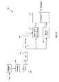
- a narrowband interference detection circuitis used. On example of one such component is shown in FIG. 8 .
- a CW detectionis done preferably each time one of the packet detectors 102 or 104 indicates a packet has been detected. It can be done at the same time as other processing, or on a buffered set of samples only after packet detection has occurred.
- Narrowband interference detectioncan be done on a single active antenna, to minimize the hardware complexity. Since the primary goal is to detect strong interference when there is no desired signal, it is not expected that using more than one antenna will significantly improve the performance of this step. However, it is possible to use more than one antenna.
- the input signalis buffered so that the last 24 samples used by the packet detectors are available.
- a window filter 604is applied to the 24 samples wherein a raised cosine window with a rolloff length of 8 samples is applied to the first 8 samples and the last 8 samples. This tends to minimize “leakage” of narrowband interference power into adjacent FFT-outputs, thereby increasing the detection probability.
- Window filter 604also “folds” over samples to result in a 16-sample set, by adding samples 1 - 4 to samples 17 - 20 and samples 21 - 24 to samples 5 - 8 .
- the effects of window filter 604are determined ahead of time and a set of 16 functions of the inputs are determined and applied to the 24 inputs to obtain the 16 values for the output of window filter 604 .
- a 16-sample FFT 606does an FFT on its window filter outputs and provides that to a power detector 608 and a maximum detector 610 .
- Maximum detector 610determines which of the FFT output samples (the m-th sample) has the maximum power.
- CW_present signalis asserted.
- controller 120receives the CW_present signal, 802.11a or 802.11b triggers are ignored.
- the CW_present signalcan be binary, it can also be multilevel, indicating a probability, confidence or certainty value (e.g. degree of certainty) associated with the determination.
- the above techniqueis usable for a single antenna, even where multiple antennas are available. Where multiple antennas are available and used, multiple instantiations might exist for FFT 606 and power detector 608 , with the outputs of multiple FFTs feeding to the multiple power detectors and the outputs of the power detectors added together.
- Power component 108estimates received signal power per antenna, which is used for automatic gain setting (AGC) of the RF receivers. A change to the RF gain is made in each of the 3 following cases:
- the RF gain of all active antennasis increased by the coarse gain step (typically the up step and the down step are the same, but they could be different);
- the power of all active antennasmight be adjusted in steps of 4 dB such that the resulting backoffs become approximately equal to some target backoff and the gain might be changed after every packet detection.
- Non-active antennasare set to a larger backoff level to prevent clipping that can happen if these antennas happen to have a significantly larger power than the active antennas.
- a programmable parameterlimits the maximum gain differences between different antennas. This is done to prevent an antenna that receives only noise to be blown up too much, since that may cause problems for the 802.11b receiver training or other situations.
- FIG. 4shows only a “pwr” output from power component 108
- power component 108might also output gain settings for each antenna. For example, once a packet is detected, controller 120 might send the gain settings (and possibly also the pwr settings) to an RF receiver to update its gain settings.
- Interference locator 110provides additional information to assist a receiver. Such information includes the frequency location of possible narrowband interference, the coarse frequency offset (df_ 11 a ) between the transmitter and receiver for 802.11a signals, signal power and noise power.
- FIG. 9shows one possible circuit (comprising components 110 A, 110 B and 110 C) for determining such location and other indicators.
- each antennais processed to determine the indicators.
- the samplesare obtained from a sample buffer 602 .
- FIG. 9AAlthough only one circuit is shown in FIG. 9A , is should be understood that the circuit is shown for the i-th antenna and multiple instances would be present for multiple antenna receivers. Alternatively, the circuit could be used in series for more than one antenna (such as where the circuit is implemented by instructions for a digital signal processor), but where performance is an issue, one circuit might be dedicated to one antenna and all the circuits implemented in dedicated hardware, such as a custom ASIC.
- the output of FFT block 606is conjugated by a conjugator 608 and the outputs of FFT block 604 and conjugator 608 are multiplied by a complex multiplier 610 to for a multiplier output Z i (k).
- the particular samples used in the exampleare based on the short training subcarriers present in the first eight microseconds of an 802.11a preamble. For variations of this process, other samples (or less than all of the ones used in the example) might be used.
- Those valuesare then used by components 110 B and 110 C as shown in FIGS. 9B and 9C , respectively.
- the correlation output values for all antennas processedare accumulated by an accumulator 620 and an angle is calculated by angle block 622 , which is the angle of the complex value output by accumulator 620 .
- the multiplier output values for all antennas processedare summed by another adder 621 .
- the output of angle block 622 and adder 621are used by a rotation block 624 to determine a phase corrected value Z′(k) that is equal to the input samples Z(k) rotated by the angle found by block 622 .
- a maximum detection block 626receives Z′(k) and outputs the maximum quadrature value as the subcarrier that represents the interference location output.
- Blocks 628 and 630provide the coarse frequency offset df_ 11 a , from a sum of the multiplier output values excluding the subcarrier corresponding to the interference location and its neighbors (one on each side).
- Component 110 C shown in FIG. 9Cis for one antenna (or multiple antennas where it could be used in that way), the i-th antenna.
- the frequency signals F ib (k) and F ia (k)are provided to magnitude blocks 640 that output the power of each of the frequency signal (or at least a proportional representation of the power) and those power signals are added by adder 642 .
- An accumulator 644sums the results over 16 samples. The accumulator result is rounded to a power of 2 by a rounder 645 and the output of rounder 645 is a signal scaling factor for the i-th antenna.
- the accumulator resultis also used for noise scaling, wherein an adder 646 subtracts twice the absolute value of the correlation output value C i for the i-th antenna from the accumulator result.
- Another rounder 648rounds the result from adder 646 to a power of 2 and that is provided as a noise scaling factor for the i-th antenna.
- the signal strengths and noise scaling factorscan be used for multiple antenna combining.
- interference and a valid packetWhen interference and a valid packet are detected, the interference might be removed and the packet processed to obtain data, but if there is interference detected and no valid packet detected, nothing else need be done.
- Narrowband filteringcan be done using the interference location, such as by filtering the signal using a band-gap filter at the interference location.
- Another approachis to pass values to a Viterbi decoder indicating a low confidence in values measured at the frequency of the interference.
- the interference detectioncan be used in other components of a receiver other than the packet detector. For example, interference location is usable in a synchronization process to ignore spurious signals.
- FIG. 10illustrates some experimental results using the above circuits for detection and producing indicators. Each of these plots is for a single active antenna and plot probabilities versus threshold values, with additive white Gaussian noise.
- FIG. 10Aillustrates 802.11a packet detection results including false alarms (packet not present, but packet detected) and missed detections (packet present, but packet not detected).
- the curve labelled “FA”represents the probability that, during a single symbol interval, a packet is falsely detected.
- the other curvesare missed detection curves, for the signal to noise ratios indicated by the labels ( ⁇ 3 dB, 0 dB, 3 dB and 6 dB).
- a detection decisionis made every symbol duration, so the probability of a false alarm within a certain number of symbols is larger than the probability shown in FIG. 10A .
- a reasonable threshold valueis ⁇ 4 dB for 802.11a.
- FIG. 10Billustrates 802.11b packet detection results including false alarms and missed detections, using similar notations and SNR values as with FIG. 10A .
- the probability of a false alarm within a certain number of symbolsis larger than the probability shown in the figure and a detection threshold should be selected for a sufficiently small false alarm probability.
- a reasonable threshold valueis ⁇ 5 dB for 802.11b.
- FIG. 10Cillustrates CW interference detection curves.
- the solid curve labelled “FA”represents the false alarm probability, wherein CW interference is detected on an OFDM preamble with 250 ns delay spread. A false alarm means that a valid OFDM preamble will be rejected even though it could have been received without interference.
- the dashed linesrepresent missed detection probabilities for signal-to-interference ratios of 0 dB, ⁇ 10 dB, ⁇ 20 dB and ⁇ 30 dB as indicated.
Landscapes
- Engineering & Computer Science (AREA)
- Quality & Reliability (AREA)
- Physics & Mathematics (AREA)
- Electromagnetism (AREA)
- Computer Networks & Wireless Communication (AREA)
- Signal Processing (AREA)
- Radio Transmission System (AREA)
- Monitoring And Testing Of Transmission In General (AREA)
Abstract
Description
| TABLE 1 |
| Controller Inputs |
| Label | Description |
| c11b | Correlation metric for 802.11b |
| df_11b | Coarse estimate for transmitter/receiver |
| frequency offset for 802.11b signals | |
| p11b | Power metric for 802.11b |
| peak_11b | Index of 802.11b signal peak |
| c11a | Correlation metric for 802.11a |
| p11a | Power metric for 802.11a |
| cw_present | Indicates presence of a narrowband interference |
| signal that is not 802.11a or 802.11b | |
| pwr | Power estimates for each antenna |
| interference_location | Frequency location of detected interference |
| (if any) | |
| df_11a | Coarse estimate for transmitter/receiver |
| frequency offset for 802.11a signals | |
| noise_estimates[N] | Estimates (per antenna) of noise level |
| scaling_factors[N] | Estimates (per antenna) of signal level; used |
| for adjusting gain of antennas | |
| TABLE 2 |
| Controller Outputs |
| Label | Description |
| detect_11b | A metric indicating the presence of an 802.11b |
| preamble | |
| detect_11a | A metric indicating the presence of an 802.11a |
| preamble | |
| peak_11b | Passthrough from interference locator |
| df_11b | Passthrough from interference locator |
| df_11a | Passthrough from interference locator |
| interference_location | Passthrough from interference locator |
| noise_estimates[N] | Passthrough from interference locator |
| scaling_factors[N] | Passthrough from interference locator |
In some embodiments where detect_11ais a multilevel signal, detect_11amight be a measure proportional to that shown in
CW Detection
Claims (12)
Priority Applications (3)
| Application Number | Priority Date | Filing Date | Title |
|---|---|---|---|
| US10/642,070US7586884B2 (en) | 2003-08-15 | 2003-08-15 | Joint packet detection in wireless communication system with one or more receiver |
| TW094108766ATW200635397A (en) | 2003-08-15 | 2005-03-22 | Joint packet detection in a wireless communication system with one or more receiver |
| US12/554,438US8023397B2 (en) | 2003-08-15 | 2009-09-04 | Joint packet detection in a wireless communication system with one or more receivers |
Applications Claiming Priority (1)
| Application Number | Priority Date | Filing Date | Title |
|---|---|---|---|
| US10/642,070US7586884B2 (en) | 2003-08-15 | 2003-08-15 | Joint packet detection in wireless communication system with one or more receiver |
Related Child Applications (1)
| Application Number | Title | Priority Date | Filing Date |
|---|---|---|---|
| US12/554,438ContinuationUS8023397B2 (en) | 2003-08-15 | 2009-09-04 | Joint packet detection in a wireless communication system with one or more receivers |
Publications (2)
| Publication Number | Publication Date |
|---|---|
| US20050152317A1 US20050152317A1 (en) | 2005-07-14 |
| US7586884B2true US7586884B2 (en) | 2009-09-08 |
Family
ID=34738921
Family Applications (2)
| Application Number | Title | Priority Date | Filing Date |
|---|---|---|---|
| US10/642,070Active2028-07-08US7586884B2 (en) | 2003-08-15 | 2003-08-15 | Joint packet detection in wireless communication system with one or more receiver |
| US12/554,438Expired - LifetimeUS8023397B2 (en) | 2003-08-15 | 2009-09-04 | Joint packet detection in a wireless communication system with one or more receivers |
Family Applications After (1)
| Application Number | Title | Priority Date | Filing Date |
|---|---|---|---|
| US12/554,438Expired - LifetimeUS8023397B2 (en) | 2003-08-15 | 2009-09-04 | Joint packet detection in a wireless communication system with one or more receivers |
Country Status (2)
| Country | Link |
|---|---|
| US (2) | US7586884B2 (en) |
| TW (1) | TW200635397A (en) |
Cited By (9)
| Publication number | Priority date | Publication date | Assignee | Title |
|---|---|---|---|---|
| US20070254594A1 (en)* | 2006-04-27 | 2007-11-01 | Kaj Jansen | Signal detection in multicarrier communication system |
| US20090238299A1 (en)* | 2004-05-27 | 2009-09-24 | Qualcomm Incorporated | Detecting the Number of Transmit Antennas in Wireless Communication Systems |
| US20100061402A1 (en)* | 2003-04-10 | 2010-03-11 | Qualcomm Incorporated | Modified preamble structure for ieee 802.11a extensions to allow for coexistence and interoperability between 802.11a devices and higher data rate, mimo or otherwise extended devices |
| US20100272157A1 (en)* | 2009-04-26 | 2010-10-28 | Ismail Lakkis | Spread spectrum encoding and decoding |
| US20100284444A1 (en)* | 2009-05-06 | 2010-11-11 | Ismail Lakkis | Method and apparatus for packet acquisition |
| US8155140B1 (en)* | 2008-11-25 | 2012-04-10 | Qualcomm Atheros, Inc. | Collision avoidance for a network system |
| US8537878B2 (en) | 2009-04-26 | 2013-09-17 | Adeptence, Llc | Spread-spectrum codes generation |
| US8611457B2 (en) | 2003-04-10 | 2013-12-17 | Qualcomm Incorporated | Modified preamble structure for IEEE 802.11A extensions to allow for coexistence and interoperability between 802.11A devices and higher data rate, MIMO or otherwise extended devices |
| US9094108B2 (en) | 2009-04-26 | 2015-07-28 | Nant Holdings Ip, Llc | Spread-spectrum modulation and demodulation |
Families Citing this family (54)
| Publication number | Priority date | Publication date | Assignee | Title |
|---|---|---|---|---|
| US7321632B2 (en)* | 2003-09-30 | 2008-01-22 | Intel Corporation | Method and apparatus for multi-algorithm detection |
| US7453853B2 (en)* | 2003-10-09 | 2008-11-18 | Ericsson Technology Licensing Ab | Adaptive correlation of access codes in a packet-based communication system |
| US7321564B2 (en)* | 2004-01-26 | 2008-01-22 | Texas Instruments Incorporated | Hybrid IMMSE-LMMSE receiver processing technique and apparatus for a MIMO WLAN |
| US7733834B2 (en)* | 2004-07-19 | 2010-06-08 | Ittiam Systems (P) Ltd. | Frame detection method for 802.11b/g based WLAN systems |
| US7551696B2 (en)* | 2004-07-20 | 2009-06-23 | Realtek Semiconductor Corp. | Method and apparatus of detecting ISI/ICSI in an OFDM system |
| US7460626B2 (en)* | 2004-07-20 | 2008-12-02 | Realtek Semiconductor Corp. | Method and apparatus of detecting ISI/ICSI in an OFDM system |
| US7539241B1 (en)* | 2004-10-22 | 2009-05-26 | Xilinx, Inc. | Packet detector for a communication system |
| JP2006129247A (en)* | 2004-10-29 | 2006-05-18 | Toshiba Corp | Information processing apparatus and communication control method |
| US7653035B2 (en)* | 2004-12-20 | 2010-01-26 | Intel Corporation | Interference rejection in wireless receivers |
| US20060193410A1 (en)* | 2005-02-28 | 2006-08-31 | Moorti R T | Gain estimation for multiple receiver systems |
| US7792227B2 (en)* | 2005-03-02 | 2010-09-07 | Broadcom Corporation | Carrier detection for multiple receiver systems |
| TWI295884B (en)* | 2005-10-26 | 2008-04-11 | Sunplus Technology Co Ltd | Method for symbol timing synchronization and apparatus thereof |
| CN101331710A (en)* | 2005-12-15 | 2008-12-24 | Nxp股份有限公司 | GSM harmonic emission desensitization in 5-GHZ WLAN |
| KR100758873B1 (en)* | 2005-12-30 | 2007-09-19 | 포스데이타 주식회사 | Frequency offset estimation device and method in wireless communication system |
| WO2007121451A2 (en) | 2006-04-17 | 2007-10-25 | Qualcomm Incorporated | Noise estimation for wireless communication |
| US7583764B2 (en)* | 2006-05-26 | 2009-09-01 | Texas Instruments Incorporated | Versatile system for interference tolerant packet detection in wireless communication systems |
| US7606139B2 (en)* | 2006-12-08 | 2009-10-20 | Intel Corporation | Preamble detection using frequency based correlation |
| US8289837B2 (en)* | 2007-05-04 | 2012-10-16 | Qualcomm Incorporated | Methods and apparatuses for multimode Bluetooth and WLAN operation concurrently |
| TWI378692B (en)* | 2007-07-06 | 2012-12-01 | Princeton Technology Corp | Device for determining pn code automatically and related method |
| US20090160696A1 (en)* | 2007-12-21 | 2009-06-25 | Ralink Technology Corporation | Configurable radar detection and avoidance system for wireless ofdm tranceivers |
| US7995616B2 (en)* | 2008-01-30 | 2011-08-09 | Qualcomm, Incorporated | Acquisition of timing information in wireless communication systems |
| US7965799B2 (en)* | 2008-02-25 | 2011-06-21 | Xilinx, Inc. | Block boundary detection for a wireless communication system |
| US8311143B2 (en)* | 2008-03-31 | 2012-11-13 | Qualcomm Incorporated | Scaling methods and apparatus using SNR estimate to avoid overflow |
| US8081615B2 (en)* | 2008-10-10 | 2011-12-20 | Mediatek Inc. | Method and apparatus to allow coexistence between wireless devices |
| JP4661938B2 (en)* | 2008-10-28 | 2011-03-30 | ソニー株式会社 | Wireless communication apparatus, wireless communication method, and computer program |
| US8335283B1 (en)* | 2008-11-11 | 2012-12-18 | Qualcomm Atheros, Inc. | Weak signal detection in wireless communication systems |
| JP5677619B2 (en) | 2012-03-07 | 2015-02-25 | 三菱電機株式会社 | Start signal generator |
| CN102664839B (en)* | 2012-04-13 | 2016-03-23 | 豪威科技(上海)有限公司 | Channel estimation methods and device |
| US10231206B2 (en) | 2013-03-15 | 2019-03-12 | DGS Global Systems, Inc. | Systems, methods, and devices for electronic spectrum management for identifying signal-emitting devices |
| US9622041B2 (en) | 2013-03-15 | 2017-04-11 | DGS Global Systems, Inc. | Systems, methods, and devices for electronic spectrum management |
| US10237770B2 (en) | 2013-03-15 | 2019-03-19 | DGS Global Systems, Inc. | Systems, methods, and devices having databases and automated reports for electronic spectrum management |
| US10257728B2 (en) | 2013-03-15 | 2019-04-09 | DGS Global Systems, Inc. | Systems, methods, and devices for electronic spectrum management |
| US12356206B2 (en) | 2013-03-15 | 2025-07-08 | Digital Global Systems, Inc. | Systems and methods for automated financial settlements for dynamic spectrum sharing |
| US11646918B2 (en) | 2013-03-15 | 2023-05-09 | Digital Global Systems, Inc. | Systems, methods, and devices for electronic spectrum management for identifying open space |
| US10271233B2 (en) | 2013-03-15 | 2019-04-23 | DGS Global Systems, Inc. | Systems, methods, and devices for automatic signal detection with temporal feature extraction within a spectrum |
| US10257729B2 (en) | 2013-03-15 | 2019-04-09 | DGS Global Systems, Inc. | Systems, methods, and devices having databases for electronic spectrum management |
| US10219163B2 (en) | 2013-03-15 | 2019-02-26 | DGS Global Systems, Inc. | Systems, methods, and devices for electronic spectrum management |
| US12256233B2 (en) | 2013-03-15 | 2025-03-18 | Digital Global Systems, Inc. | Systems and methods for automated financial settlements for dynamic spectrum sharing |
| US10257727B2 (en) | 2013-03-15 | 2019-04-09 | DGS Global Systems, Inc. | Systems methods, and devices having databases and automated reports for electronic spectrum management |
| US10299149B2 (en) | 2013-03-15 | 2019-05-21 | DGS Global Systems, Inc. | Systems, methods, and devices for electronic spectrum management |
| US9331834B2 (en)* | 2013-10-03 | 2016-05-03 | Amlogic Co., Limited | Channel bandwidth detection |
| US9106300B1 (en)* | 2013-10-18 | 2015-08-11 | Marvell International Ltd. | Method and apparatus for detecting narrow-band interference in a communication system |
| TWI605690B (en)* | 2016-09-06 | 2017-11-11 | 晨星半導體股份有限公司 | Device and Method of Handling Symbol Rate Estimation and Interference |
| US12205477B2 (en) | 2017-01-23 | 2025-01-21 | Digital Global Systems, Inc. | Unmanned vehicle recognition and threat management |
| US10529241B2 (en) | 2017-01-23 | 2020-01-07 | Digital Global Systems, Inc. | Unmanned vehicle recognition and threat management |
| US10459020B2 (en) | 2017-01-23 | 2019-10-29 | DGS Global Systems, Inc. | Systems, methods, and devices for automatic signal detection based on power distribution by frequency over time within a spectrum |
| US10498951B2 (en) | 2017-01-23 | 2019-12-03 | Digital Global Systems, Inc. | Systems, methods, and devices for unmanned vehicle detection |
| US10700794B2 (en) | 2017-01-23 | 2020-06-30 | Digital Global Systems, Inc. | Systems, methods, and devices for automatic signal detection based on power distribution by frequency over time within an electromagnetic spectrum |
| US12183213B1 (en) | 2017-01-23 | 2024-12-31 | Digital Global Systems, Inc. | Unmanned vehicle recognition and threat management |
| KR101924993B1 (en)* | 2017-02-15 | 2018-12-04 | (주)에프씨아이 | Apparatus and Method For Providing Automatic Gain Control |
| TWI629886B (en)* | 2017-03-08 | 2018-07-11 | 安華聯網科技股份有限公司 | Packet analysis apparatus, method, and computer program product thereof |
| US10374646B1 (en)* | 2018-02-07 | 2019-08-06 | Cubic Corporation | Crowd size estimation based on wireless signal absorption |
| US10659941B2 (en) | 2018-03-13 | 2020-05-19 | Cypress Semiconductor Corporation | Communicating packets in a mesh network |
| US10943461B2 (en) | 2018-08-24 | 2021-03-09 | Digital Global Systems, Inc. | Systems, methods, and devices for automatic signal detection based on power distribution by frequency over time |
Citations (28)
| Publication number | Priority date | Publication date | Assignee | Title |
|---|---|---|---|---|
| US5131006A (en)* | 1990-09-06 | 1992-07-14 | Ncr Corporation | Carrier detection for a wireless local area network |
| US5694421A (en)* | 1995-03-17 | 1997-12-02 | Samsung Electronics Co., Ltd. | Frequency-selective interference signal detecting apparatus and method thereof |
| WO2001005088A1 (en)* | 1999-07-07 | 2001-01-18 | Telefonaktiebolaget Lm Ericsson (Publ) | Controlled antenna diversity |
| US6226508B1 (en)* | 1997-07-04 | 2001-05-01 | Matsushita Electric Industrial Co., Ltd. | Transmission diversity apparatus |
| US20020012411A1 (en)* | 2000-04-05 | 2002-01-31 | Johann Heinzl | Global positioning system receiver capable of functioning in the presence of interference |
| US20020122511A1 (en)* | 2000-09-01 | 2002-09-05 | Alan Kwentus | Satellite receiver |
| US20030072397A1 (en) | 2001-08-17 | 2003-04-17 | Younggyun Kim | Digital front-end for wireless communication system |
| US20030236108A1 (en)* | 2000-11-15 | 2003-12-25 | Jiang Li | Spatial domain matched filtering method and array receiver in wireless communication system |
| US20040001430A1 (en)* | 2002-04-18 | 2004-01-01 | Gardner Steven H. | Method and apparatus for preamble detection and time synchronization estimation in OFDM communication systems |
| US20040005022A1 (en)* | 2002-07-03 | 2004-01-08 | Oki Techno Centre (Singapore) Pte Ltd. | Receiver and method for WLAN burst type signals |
| US20040030530A1 (en) | 2002-01-30 | 2004-02-12 | Kuo-Hui Li | Apparatus and method for detection of direct sequence spread spectrum signals in networking systems |
| US20040032825A1 (en)* | 2002-08-19 | 2004-02-19 | Halford Steven D. | Wireless receiver for sorting packets |
| US20040048574A1 (en)* | 2001-09-26 | 2004-03-11 | General Atomics | Method and apparatus for adapting multi-band ultra-wideband signaling to interference sources |
| US20040052231A1 (en)* | 2002-03-18 | 2004-03-18 | Kumar Ramaswamy | Method and apparatus for indicating the presence of a wireless local area network by detecting signature sequences |
| WO2004027921A2 (en) | 2002-09-17 | 2004-04-01 | Ipr Licensing, Inc. | Multiple pattern antenna |
| US20040071104A1 (en)* | 2002-07-03 | 2004-04-15 | Commasic, Inc. | Multi-mode method and apparatus for performing digital modulation and demodulation |
| US20040116112A1 (en) | 2001-03-08 | 2004-06-17 | Gray Steven D. | Apparatus, and associated method, for reporting a measurement summary in a radio communication system |
| US20040240402A1 (en)* | 2003-05-27 | 2004-12-02 | Stephens Adrian P. | Multiple mode support in a wireless local area network |
| US20040258025A1 (en) | 2003-06-18 | 2004-12-23 | University Of Florida | Wireless lan compatible multi-input multi-output system |
| US20040266375A1 (en)* | 2003-06-27 | 2004-12-30 | Qinghua Li | Switching schemes for multiple antennas |
| US20050002327A1 (en)* | 2003-04-07 | 2005-01-06 | Shaolin Li | Single chip multi-antenna wireless data processor |
| US20050018754A1 (en)* | 1999-03-15 | 2005-01-27 | Lg Electronics Inc. | Pilot signals for synchronization and/or channel estimation |
| US20050047384A1 (en) | 2003-08-27 | 2005-03-03 | Wavion Ltd. | WLAN capacity enhancement using SDM |
| US20050233709A1 (en)* | 2003-04-10 | 2005-10-20 | Airgo Networks, Inc. | Modified preamble structure for IEEE 802.11a extensions to allow for coexistence and interoperability between 802.11a devices and higher data rate, MIMO or otherwise extended devices |
| US20060013327A1 (en)* | 2002-03-01 | 2006-01-19 | Ipr Licensing, Inc. | Apparatus for antenna diversity using joint maximal ratio combining |
| US20060013180A1 (en)* | 2004-07-19 | 2006-01-19 | Ittiam Systems (P) Ltd. | Frame detection method for 802.11b/g based WLAN systems |
| US7123662B2 (en)* | 2001-08-15 | 2006-10-17 | Mediatek Inc. | OFDM detection apparatus and method for networking devices |
| US20070117523A1 (en)* | 2002-08-13 | 2007-05-24 | David Weber | Method And Apparatus For Signal Power Loss Reduction In RF Communication Systems |
Family Cites Families (13)
| Publication number | Priority date | Publication date | Assignee | Title |
|---|---|---|---|---|
| JP2970347B2 (en) | 1993-09-28 | 1999-11-02 | 住友電装株式会社 | connector |
| EP0871253B1 (en) | 1993-12-06 | 2001-12-12 | Sumitomo Wiring Systems, Ltd. | Lock detection connector |
| JPH07211392A (en) | 1994-01-21 | 1995-08-11 | Sumitomo Wiring Syst Ltd | Connector |
| US7161987B2 (en) | 2001-09-26 | 2007-01-09 | Conexant, Inc. | Single-carrier to multi-carrier wireless architecture |
| JP3946987B2 (en) | 2001-11-28 | 2007-07-18 | インターナショナル・ビジネス・マシーンズ・コーポレーション | Multi-band communication apparatus and communication method thereof |
| US6763844B2 (en)* | 2002-07-30 | 2004-07-20 | Aling Lai | Fuel tank structure of a remotely controllable car |
| US7647069B2 (en)* | 2002-10-25 | 2010-01-12 | Nxp B.V. | Single oscillator DSSS and OFDM radio receiver |
| JP3779673B2 (en) | 2002-10-30 | 2006-05-31 | 株式会社東芝 | Relay device and communication system |
| JP2004214726A (en) | 2002-12-26 | 2004-07-29 | Sony Corp | Radio communication antenna and apparatus thereof |
| US7421276B2 (en)* | 2003-04-09 | 2008-09-02 | Nortel Networks Limited | Method, apparatus and system of configuring a wireless device based on location |
| JP2004289373A (en) | 2003-03-20 | 2004-10-14 | Tdk Corp | Wireless communication system, wireless terminal device, and method for switching communication system |
| JP2004328267A (en) | 2003-04-23 | 2004-11-18 | Canon Inc | Network system and control method thereof |
| EP1661253A1 (en) | 2003-08-29 | 2006-05-31 | Koninklijke Philips Electronics N.V. | System and method for energy efficient signal detection in a wireless network device |
- 2003
- 2003-08-15USUS10/642,070patent/US7586884B2/enactiveActive
- 2005
- 2005-03-22TWTW094108766Apatent/TW200635397A/enunknown
- 2009
- 2009-09-04USUS12/554,438patent/US8023397B2/ennot_activeExpired - Lifetime
Patent Citations (29)
| Publication number | Priority date | Publication date | Assignee | Title |
|---|---|---|---|---|
| US5131006A (en)* | 1990-09-06 | 1992-07-14 | Ncr Corporation | Carrier detection for a wireless local area network |
| US5694421A (en)* | 1995-03-17 | 1997-12-02 | Samsung Electronics Co., Ltd. | Frequency-selective interference signal detecting apparatus and method thereof |
| US6226508B1 (en)* | 1997-07-04 | 2001-05-01 | Matsushita Electric Industrial Co., Ltd. | Transmission diversity apparatus |
| US20050018754A1 (en)* | 1999-03-15 | 2005-01-27 | Lg Electronics Inc. | Pilot signals for synchronization and/or channel estimation |
| WO2001005088A1 (en)* | 1999-07-07 | 2001-01-18 | Telefonaktiebolaget Lm Ericsson (Publ) | Controlled antenna diversity |
| US20020012411A1 (en)* | 2000-04-05 | 2002-01-31 | Johann Heinzl | Global positioning system receiver capable of functioning in the presence of interference |
| US20020122511A1 (en)* | 2000-09-01 | 2002-09-05 | Alan Kwentus | Satellite receiver |
| US20030236108A1 (en)* | 2000-11-15 | 2003-12-25 | Jiang Li | Spatial domain matched filtering method and array receiver in wireless communication system |
| US20040116112A1 (en) | 2001-03-08 | 2004-06-17 | Gray Steven D. | Apparatus, and associated method, for reporting a measurement summary in a radio communication system |
| US7123662B2 (en)* | 2001-08-15 | 2006-10-17 | Mediatek Inc. | OFDM detection apparatus and method for networking devices |
| US20030072397A1 (en) | 2001-08-17 | 2003-04-17 | Younggyun Kim | Digital front-end for wireless communication system |
| US7190748B2 (en)* | 2001-08-17 | 2007-03-13 | Dsp Group Inc. | Digital front-end for wireless communication system |
| US20040048574A1 (en)* | 2001-09-26 | 2004-03-11 | General Atomics | Method and apparatus for adapting multi-band ultra-wideband signaling to interference sources |
| US20040030530A1 (en) | 2002-01-30 | 2004-02-12 | Kuo-Hui Li | Apparatus and method for detection of direct sequence spread spectrum signals in networking systems |
| US20060013327A1 (en)* | 2002-03-01 | 2006-01-19 | Ipr Licensing, Inc. | Apparatus for antenna diversity using joint maximal ratio combining |
| US20040052231A1 (en)* | 2002-03-18 | 2004-03-18 | Kumar Ramaswamy | Method and apparatus for indicating the presence of a wireless local area network by detecting signature sequences |
| US20040001430A1 (en)* | 2002-04-18 | 2004-01-01 | Gardner Steven H. | Method and apparatus for preamble detection and time synchronization estimation in OFDM communication systems |
| US20040005022A1 (en)* | 2002-07-03 | 2004-01-08 | Oki Techno Centre (Singapore) Pte Ltd. | Receiver and method for WLAN burst type signals |
| US20040071104A1 (en)* | 2002-07-03 | 2004-04-15 | Commasic, Inc. | Multi-mode method and apparatus for performing digital modulation and demodulation |
| US20070117523A1 (en)* | 2002-08-13 | 2007-05-24 | David Weber | Method And Apparatus For Signal Power Loss Reduction In RF Communication Systems |
| US20040032825A1 (en)* | 2002-08-19 | 2004-02-19 | Halford Steven D. | Wireless receiver for sorting packets |
| WO2004027921A2 (en) | 2002-09-17 | 2004-04-01 | Ipr Licensing, Inc. | Multiple pattern antenna |
| US20050002327A1 (en)* | 2003-04-07 | 2005-01-06 | Shaolin Li | Single chip multi-antenna wireless data processor |
| US20050233709A1 (en)* | 2003-04-10 | 2005-10-20 | Airgo Networks, Inc. | Modified preamble structure for IEEE 802.11a extensions to allow for coexistence and interoperability between 802.11a devices and higher data rate, MIMO or otherwise extended devices |
| US20040240402A1 (en)* | 2003-05-27 | 2004-12-02 | Stephens Adrian P. | Multiple mode support in a wireless local area network |
| US20040258025A1 (en) | 2003-06-18 | 2004-12-23 | University Of Florida | Wireless lan compatible multi-input multi-output system |
| US20040266375A1 (en)* | 2003-06-27 | 2004-12-30 | Qinghua Li | Switching schemes for multiple antennas |
| US20050047384A1 (en) | 2003-08-27 | 2005-03-03 | Wavion Ltd. | WLAN capacity enhancement using SDM |
| US20060013180A1 (en)* | 2004-07-19 | 2006-01-19 | Ittiam Systems (P) Ltd. | Frame detection method for 802.11b/g based WLAN systems |
Cited By (14)
| Publication number | Priority date | Publication date | Assignee | Title |
|---|---|---|---|---|
| US20100061402A1 (en)* | 2003-04-10 | 2010-03-11 | Qualcomm Incorporated | Modified preamble structure for ieee 802.11a extensions to allow for coexistence and interoperability between 802.11a devices and higher data rate, mimo or otherwise extended devices |
| US8743837B2 (en) | 2003-04-10 | 2014-06-03 | Qualcomm Incorporated | Modified preamble structure for IEEE 802.11A extensions to allow for coexistence and interoperability between 802.11A devices and higher data rate, MIMO or otherwise extended devices |
| US8611457B2 (en) | 2003-04-10 | 2013-12-17 | Qualcomm Incorporated | Modified preamble structure for IEEE 802.11A extensions to allow for coexistence and interoperability between 802.11A devices and higher data rate, MIMO or otherwise extended devices |
| US8457232B2 (en) | 2004-05-27 | 2013-06-04 | Qualcomm Incorporated | Detecting the number of transmit antennas in wireless communication systems |
| US20090238299A1 (en)* | 2004-05-27 | 2009-09-24 | Qualcomm Incorporated | Detecting the Number of Transmit Antennas in Wireless Communication Systems |
| US20070254594A1 (en)* | 2006-04-27 | 2007-11-01 | Kaj Jansen | Signal detection in multicarrier communication system |
| US8155140B1 (en)* | 2008-11-25 | 2012-04-10 | Qualcomm Atheros, Inc. | Collision avoidance for a network system |
| US20100272157A1 (en)* | 2009-04-26 | 2010-10-28 | Ismail Lakkis | Spread spectrum encoding and decoding |
| US8537878B2 (en) | 2009-04-26 | 2013-09-17 | Adeptence, Llc | Spread-spectrum codes generation |
| US8804790B2 (en) | 2009-04-26 | 2014-08-12 | Adeptence, Llc | Spread spectrum encoding and decoding |
| US9094108B2 (en) | 2009-04-26 | 2015-07-28 | Nant Holdings Ip, Llc | Spread-spectrum modulation and demodulation |
| US8401056B2 (en)* | 2009-05-06 | 2013-03-19 | Adeptence Llc | Method and apparatus for packet acquisition |
| US8693521B2 (en)* | 2009-05-06 | 2014-04-08 | Adeptence, Llc | Method and apparatus for packet acquisition |
| US20100284444A1 (en)* | 2009-05-06 | 2010-11-11 | Ismail Lakkis | Method and apparatus for packet acquisition |
Also Published As
| Publication number | Publication date |
|---|---|
| US8023397B2 (en) | 2011-09-20 |
| TW200635397A (en) | 2006-10-01 |
| US20100061262A1 (en) | 2010-03-11 |
| US20050152317A1 (en) | 2005-07-14 |
Similar Documents
| Publication | Publication Date | Title |
|---|---|---|
| US7586884B2 (en) | Joint packet detection in wireless communication system with one or more receiver | |
| US7627059B2 (en) | Method of robust timing detection and carrier frequency offset estimation for OFDM systems | |
| US7596154B2 (en) | Method and device for synchronisation in OFDM | |
| CN101449534B (en) | Jointed grouping detection in wireless communication system having one or more receivers | |
| US7864884B2 (en) | Signal detection in OFDM system | |
| US7480234B1 (en) | Initial timing estimation in a wireless network receiver | |
| US8045927B2 (en) | Signal detection in multicarrier communication system | |
| US7203254B2 (en) | Method and system for synchronizing in a frequency shift keying receiver | |
| JP5571147B2 (en) | Adaptive packet detection for detecting packets in wireless media | |
| US7280605B2 (en) | Orthogonal frequency division multiplexing (OFDM) receiver used in wireless local area network system and symbol timing synchronization method therefor | |
| US20060269008A1 (en) | Receiving apparatus and synchronising method for a digital telecommunication system | |
| US7751520B1 (en) | Packet detection, synchronization, and frequency offset estimation | |
| US8306167B2 (en) | Method of synchronization for packet based, OFDM wireless systems with multiple receive chains | |
| US6785350B1 (en) | Apparatus, and associated method, for detecting a symbol sequence | |
| US8045948B2 (en) | Receiving apparatus, program and receiving method | |
| US7443938B2 (en) | Method and system for synchronization between transmitter and receiver in a communication system | |
| US7346098B2 (en) | Communication receiver | |
| EP2063596B1 (en) | Joint packet detection in a wireless communication system with one or more receiver | |
| KR101126991B1 (en) | Joint packet detection in a wireless communication system with one or more receiver | |
| JP3795885B2 (en) | Reception device and reception control method | |
| JP5410478B2 (en) | Integrated packet detection in a wireless communication system with one or more receivers | |
| US8255000B2 (en) | Process for computing a frequency offset for a UMTS communication system based on the CPICH pilot signals |
Legal Events
| Date | Code | Title | Description |
|---|---|---|---|
| AS | Assignment | Owner name:AIRGO NETWORKS, INC., CALIFORNIA Free format text:ASSIGNMENT OF ASSIGNORS INTEREST;ASSIGNORS:AWATER, GEERT ARNOUT;GARDNER, JAMES;VAN NEE, RICHARD;AND OTHERS;REEL/FRAME:014961/0182;SIGNING DATES FROM 20040121 TO 20040122 | |
| AS | Assignment | Owner name:QUALCOMM INCORPORATED,CALIFORNIA Free format text:SECURITY AGREEMENT;ASSIGNOR:AIRGO NETWORKS, INC.;REEL/FRAME:018293/0332 Effective date:20060920 Owner name:COMERICA BANK,CALIFORNIA Free format text:SECURITY AGREEMENT;ASSIGNOR:AIRGO NETWORKS, INC.;REEL/FRAME:018293/0344 Effective date:20060921 Owner name:COMERICA BANK, CALIFORNIA Free format text:SECURITY AGREEMENT;ASSIGNOR:AIRGO NETWORKS, INC.;REEL/FRAME:018293/0344 Effective date:20060921 Owner name:QUALCOMM INCORPORATED, CALIFORNIA Free format text:SECURITY AGREEMENT;ASSIGNOR:AIRGO NETWORKS, INC.;REEL/FRAME:018293/0332 Effective date:20060920 | |
| AS | Assignment | Owner name:COMERICA BANK,CALIFORNIA Free format text:SECURITY AGREEMENT;ASSIGNOR:AIRGO NETWORKS, INC.;REEL/FRAME:018461/0180 Effective date:20060920 Owner name:COMERICA BANK, CALIFORNIA Free format text:SECURITY AGREEMENT;ASSIGNOR:AIRGO NETWORKS, INC.;REEL/FRAME:018461/0180 Effective date:20060920 | |
| AS | Assignment | Owner name:QUALCOMM INCORPORATED,CALIFORNIA Free format text:MERGER;ASSIGNOR:AIRGO NETWORKS, INC.;REEL/FRAME:018932/0566 Effective date:20070226 Owner name:QUALCOMM INCORPORATED, CALIFORNIA Free format text:MERGER;ASSIGNOR:AIRGO NETWORKS, INC.;REEL/FRAME:018932/0566 Effective date:20070226 | |
| AS | Assignment | Owner name:AIRGO NETWORKS INC., CALIFORNIA Free format text:RELEASE BY SECURED PARTY;ASSIGNOR:COMERICA BANK;REEL/FRAME:021253/0765 Effective date:20080716 Owner name:AIRGO NETWORKS INC.,CALIFORNIA Free format text:RELEASE BY SECURED PARTY;ASSIGNOR:COMERICA BANK;REEL/FRAME:021253/0765 Effective date:20080716 | |
| STCF | Information on status: patent grant | Free format text:PATENTED CASE | |
| CC | Certificate of correction | ||
| FPAY | Fee payment | Year of fee payment:4 | |
| FPAY | Fee payment | Year of fee payment:8 | |
| MAFP | Maintenance fee payment | Free format text:PAYMENT OF MAINTENANCE FEE, 12TH YEAR, LARGE ENTITY (ORIGINAL EVENT CODE: M1553); ENTITY STATUS OF PATENT OWNER: LARGE ENTITY Year of fee payment:12 |