US7586480B2 - Hybrid pointing device - Google Patents
Hybrid pointing deviceDownload PDFInfo
- Publication number
- US7586480B2 US7586480B2US11/069,341US6934105AUS7586480B2US 7586480 B2US7586480 B2US 7586480B2US 6934105 AUS6934105 AUS 6934105AUS 7586480 B2US7586480 B2US 7586480B2
- Authority
- US
- United States
- Prior art keywords
- puck
- motion
- region
- pointing device
- field
- Prior art date
- Legal status (The legal status is an assumption and is not a legal conclusion. Google has not performed a legal analysis and makes no representation as to the accuracy of the status listed.)
- Expired - Fee Related, expires
Links
Images


Classifications
- G—PHYSICS
- G06—COMPUTING OR CALCULATING; COUNTING
- G06F—ELECTRIC DIGITAL DATA PROCESSING
- G06F3/00—Input arrangements for transferring data to be processed into a form capable of being handled by the computer; Output arrangements for transferring data from processing unit to output unit, e.g. interface arrangements
- G06F3/01—Input arrangements or combined input and output arrangements for interaction between user and computer
- G06F3/03—Arrangements for converting the position or the displacement of a member into a coded form
- G06F3/033—Pointing devices displaced or positioned by the user, e.g. mice, trackballs, pens or joysticks; Accessories therefor
- G06F3/038—Control and interface arrangements therefor, e.g. drivers or device-embedded control circuitry
- G—PHYSICS
- G06—COMPUTING OR CALCULATING; COUNTING
- G06F—ELECTRIC DIGITAL DATA PROCESSING
- G06F3/00—Input arrangements for transferring data to be processed into a form capable of being handled by the computer; Output arrangements for transferring data from processing unit to output unit, e.g. interface arrangements
- G06F3/01—Input arrangements or combined input and output arrangements for interaction between user and computer
- G06F3/03—Arrangements for converting the position or the displacement of a member into a coded form
- G06F3/033—Pointing devices displaced or positioned by the user, e.g. mice, trackballs, pens or joysticks; Accessories therefor
- G06F3/0338—Pointing devices displaced or positioned by the user, e.g. mice, trackballs, pens or joysticks; Accessories therefor with detection of limited linear or angular displacement of an operating part of the device from a neutral position, e.g. isotonic or isometric joysticks
- G—PHYSICS
- G06—COMPUTING OR CALCULATING; COUNTING
- G06F—ELECTRIC DIGITAL DATA PROCESSING
- G06F3/00—Input arrangements for transferring data to be processed into a form capable of being handled by the computer; Output arrangements for transferring data from processing unit to output unit, e.g. interface arrangements
- G06F3/01—Input arrangements or combined input and output arrangements for interaction between user and computer
- G06F3/03—Arrangements for converting the position or the displacement of a member into a coded form
- G06F3/033—Pointing devices displaced or positioned by the user, e.g. mice, trackballs, pens or joysticks; Accessories therefor
- G06F3/0354—Pointing devices displaced or positioned by the user, e.g. mice, trackballs, pens or joysticks; Accessories therefor with detection of 2D relative movements between the device, or an operating part thereof, and a plane or surface, e.g. 2D mice, trackballs, pens or pucks
- G06F3/03548—Sliders, in which the moving part moves in a plane
- G—PHYSICS
- G06—COMPUTING OR CALCULATING; COUNTING
- G06F—ELECTRIC DIGITAL DATA PROCESSING
- G06F3/00—Input arrangements for transferring data to be processed into a form capable of being handled by the computer; Output arrangements for transferring data from processing unit to output unit, e.g. interface arrangements
- G06F3/01—Input arrangements or combined input and output arrangements for interaction between user and computer
- G06F3/048—Interaction techniques based on graphical user interfaces [GUI]
- G06F3/0484—Interaction techniques based on graphical user interfaces [GUI] for the control of specific functions or operations, e.g. selecting or manipulating an object, an image or a displayed text element, setting a parameter value or selecting a range
- G06F3/0485—Scrolling or panning
- G—PHYSICS
- G05—CONTROLLING; REGULATING
- G05G—CONTROL DEVICES OR SYSTEMS INSOFAR AS CHARACTERISED BY MECHANICAL FEATURES ONLY
- G05G9/00—Manually-actuated control mechanisms provided with one single controlling member co-operating with two or more controlled members, e.g. selectively, simultaneously
- G05G9/02—Manually-actuated control mechanisms provided with one single controlling member co-operating with two or more controlled members, e.g. selectively, simultaneously the controlling member being movable in different independent ways, movement in each individual way actuating one controlled member only
- G05G9/04—Manually-actuated control mechanisms provided with one single controlling member co-operating with two or more controlled members, e.g. selectively, simultaneously the controlling member being movable in different independent ways, movement in each individual way actuating one controlled member only in which movement in two or more ways can occur simultaneously
- G05G9/047—Manually-actuated control mechanisms provided with one single controlling member co-operating with two or more controlled members, e.g. selectively, simultaneously the controlling member being movable in different independent ways, movement in each individual way actuating one controlled member only in which movement in two or more ways can occur simultaneously the controlling member being movable by hand about orthogonal axes, e.g. joysticks
- G05G2009/04703—Mounting of controlling member
- G05G2009/04714—Mounting of controlling member with orthogonal axes
Definitions
- Modern computer operating systems and graphics programsrequire a pointing device for controlling the position of a cursor on the computer display.
- handheld devicessuch as personal information managers and cell phones would also benefit from the inclusion of such a pointing device.
- the most successful pointing deviceis the “mouse”.
- a mouseis a hand held object that is moved over a flat surface near the keyboard to control the motion of a cursor on the computer display. The direction and distance over which the mouse is moved determines the direction and distance the cursor moves on the display.
- a conventional mouseprovides a rigid object that a user can move with great precision.
- the mouseprovides a satisfactory solution to the pointing problem.
- the workspaceis not large enough to provide a path over which the mouse can move and accommodate a desired cursor movement on the screen, the user simply picks up the mouse and recenters the mouse in the workspace.
- a pointing device for use in these environmentsmust solve the problem of moving a cursor quickly and accurately.
- the devicemust operate in an intuitive fashion that a novice user can comprehend without extensive instruction.
- the pointing devicemust operate in a limited workspace and fit within the form factor of the hand held device.
- the TrackPointTMis a small button that is typically placed in the center of the laptop keyboard.
- the buttonmay be moved in a manner analogous to a “joy stick” by applying a lateral force to the top of the button with a finger.
- the buttoncan only move a small amount; hence, the displacement of the button cannot be mapped directly into a displacement in the cursor position on the computer display. Instead, the button displacement controls the direction and speed with which the cursor moves.
- the TouchPadTMis a blank rectangular pad, 50 to 100 mm on a side, typically placed below the keyboard of most laptops.
- the devicesenses the position of a finger on the surface of the rectangle relative to the edges of the device. This sensing is accomplished by measuring the capacitance changes introduced by a user finger on a series of electrodes beneath an insulating, low-friction material.
- the TouchPadTMLike the TrackPointTM, the TouchPadTM also suffers from lack of precision. It is inherently difficult to measure the capacitive changes introduced by the user, who is at an unknown potential relative to the circuit. Furthermore, the contact area of the user's finger is relatively large. Hence, to provide an accurate measurement of the finger position, the device must determine some parameter such as the center of the contact area between the finger and the pad. Unfortunately, the contact area varies in size and shape with the pressure applied by the user. Therefore, such determinations are, at best, of limited precision. In practice, users are unable to repeatably execute precise movements.
- the pointing deviceutilizes a puck that moves in a defined field of motion when a user applies pressure to the puck via the user's finger.
- a set of springsreturns the puck to its centered position within the field of motion.
- the position of the puck and the pressure on the puckare determined by electrodes in the device.
- the position informationis used to position a cursor on the display screen.
- Software on the attached devicetranslates the motion of the puck during the time the user's finger is pressing on the puck into the appropriate cursor motion on the device's display.
- the coupling between the puck and the cursor positionis broken by the software, and hence, the cursor does not move backwards while the puck is being recentered.
- the device taught in the above-described patent applicationprovides significant advantages over the dominant prior art solutions to the pointing device problem in the laptop marketplace, the device is less than optimum when used with a cell phone or other device with a relatively small screen.
- the ability to reposition the puck and then continue the motion in a manner analogous to that of mouse on a desktop computeris of limited value, since the amount of information available in the display is relatively limited, and hence, can be adequately accessed by a one-to-one mapping of the puck position to the position of the cursor on the screen.
- the limited screen sizeplaces a premium on other operations such as scrolling.
- the small screen of a handheld devicesuch as a cell phone can emulate a small window through which a much larger desktop is viewed. By moving the window in various directions, the desired portion of the desktop can be positioned under the window. Objects on the desktop under the window can then be selected by moving the cursor within the window.
- a pointing device for use in such an environmentwould benefit from having both a pointing function and a two-dimensional scrolling function.
- the present inventionincludes a pointing device having a movable puck and a display screen.
- the puckis confined to move on a puck surface having a puck field of motion defined thereon.
- the puck field of motionis divided into a pointing region and a function region.
- a controllerdetermines a position for the puck within the field of motion.
- the display screendisplays a two-dimensional scene and a cursor that moves within the scene in a manner controlled by the position of the puck when the puck is in the pointing region.
- the controllercauses the scene to change when the puck is in the function region.
- a deformable barrierinhibits the movement of the puck into the function region. The inhibition is overcome by a user applying additional force to the puck in a direction parallel to the surface.
- the deformable barrierincludes a resilient member disposed between the puck and a non-deformable barrier on the periphery of the field of motion.
- the deformable barrierincludes a spring.
- the scenerepresents a view of a portion of a surface as seen through a window movable over the surface.
- the controllercauses the portion of the surface so viewed to change to an adjacent portion of the surface when the puck moves into the function region.
- the windowmoves at a speed that depends on the position of the puck in the function region in one embodiment.
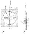
- FIG. 1is a top view of pointing device 10 .
- FIG. 2is a cross-sectional view of pointing device 10 through line 2 - 2 shown in FIG. 1 .
- FIG. 3is a top view of a portion of surface 12 shown in FIG. 1 over which the puck moves in one embodiment of the present invention.
- FIG. 4is a schematic drawing of an equivalent circuit for electrodes 51 - 55 .
- FIG. 5is a cross-sectional view of a puck 70 that utilizes a dome-shaped clicker that can be incorporated in the puck.
- FIG. 6Ais schematic drawing of a handheld device according to one embodiment of the present invention.
- FIG. 6Bis a top view of the corresponding desktop and viewing window shown in FIG. 6A .
- FIG. 7a cross-sectional view of a pointing device 100 according to one embodiment of the present invention.
- FIG. 8is a cross-sectional view of pointing device 120 according to another embodiment of the present invention.
- FIGS. 1 and 2illustrate a pointing device 10 according to one embodiment of the invention taught in the above-described patent application.
- FIG. 1is a top view of pointing device 10
- FIG. 2is a cross-sectional view of pointing device 10 through line 2 - 2 shown in FIG. 1 .
- Pointing device 10includes a puck 11 that moves over a surface 12 of a substrate 15 within a puck field of motion 19 in response to a lateral force applied to puck 11 . The force is typically applied to puck 11 by a user's finger.
- Puck 11includes a pressure sensing mechanism that measures the vertical pressure applied to puck 11 .
- pointing device 10includes a sensing mechanism for determining the position of puck 11 on surface 12 .
- puck 11When the user releases puck 11 by removing the user's finger 16 , puck 11 is returned to its centered position by the springs shown at 13 that connect the puck to the side 14 of the puck field of motion. Since the user's finger is not applying a vertical force to puck 11 during its return, the change in position associated with that return motion is not reported to the host device. That is, the cursor remains at its previous location. This provides a convenient “re-centering” capability, typically achieved on a mouse by lifting and replacing the mouse at the center of the field of motion. Re-centering is particularly necessary in laptop computers, hand-held devices and other miniature applications in which the field of motion is constrained.
- a puck having a top surface that can move vertically relative to the bottom surfacecan be utilized.
- the top surfaceis held in place by a spring mechanism.
- the top surfacemoves toward the bottom surface by an amount that depends on the applied pressure.
- the distance between the top and bottom surfaces of the puckis measured utilizing one of a number of methods.
- the top and bottom surfaces of the puckcan include conducting layers that form a parallel plate capacitor. The capacitance of this capacitor depends on the distance between the plates, and hence, a measurement of the capacitance provides a measurement of the pressure applied by the user.
- FIG. 3is a top view of a portion of surface 12 shown in FIG. 1 over which the puck moves in one embodiment of the present invention.
- Surface 50includes four electrodes shown at 51 - 54 having terminals that are connected to an external circuit. To simplify the drawing, these terminals have been omitted.
- the puckhas a bottom surface that includes an electrode 55 that is shown in phantom in the drawing. Electrodes 51 - 55 are electrically isolated from one another.
- electrode 55can be covered with a layer of dielectric that provides the required insulation while still allowing electrode 55 to slide over the other electrodes.
- the electrodescan in fact be patterned on the back of the substrate whose surface is shown at 50 . This reduces the capacitance between the electrodes and the puck electrode, but can be practical for substrate thicknesses of a few millimeters or less.
- the overlap between electrode 55 and each of electrodes 51 - 54depends on the position of the puck relative to electrodes 51 - 54 . Denote the overlaps between electrode 55 and electrodes 51 - 54 by A-D, respectively.
- FIG. 4is a schematic drawing of an equivalent circuit for electrodes 51 - 55 .
- the portion of electrode 55 that overlaps electrode 51forms a parallel plate capacitor having a capacitance that is proportional to overlap A.
- the portion of electrode 55 that overlaps electrode 52forms a parallel plate capacitor that has a capacitance that is proportional to overlap B, and so on. Since all of the capacitors share portions of electrode 55 , the equivalent circuit consists of four capacitors connected to a common electrode. This electrode is electrode 55 .
- the position of electrode 55 relative to electrodes 51 - 54can be determined. This determination can be made by a controller 59 , which may be part of the pointing device or part of the host device of which the pointing device forms a part.
- FIG. 5is a cross-sectional view of a puck 70 that utilizes such a clicker.
- Puck 70has a bottom electrode 73 whose capacitance is used to determine the position of the puck in the field of motion as described above.
- Puck 70also includes a top electrode 74 that is depressed when the user presses on the electrode.
- Top electrode 74is spring mounted to force that electrode against the detents shown at 72 when the user is not pressing on the electrode.
- a number of springs 71provide this function.
- the distance between electrodes 73 and 74can be determined by measuring the capacitance between these electrodes.
- the electrodemoves downward until it reaches the top of clicker 75 .
- clicker 75will snap to a configuration in which the dome is inverted. This will relieve the upward force on electrode 74 , and electrode 74 will move closer to electrode 75 . This new position can be sensed by measuring the capacitance between electrodes 74 and 75 .
- the clicker shown in FIG. 5is constructed from a dome-shaped sheet of material that has a height that changes abruptly when the dome is depressed below a predetermined height.
- the change in statesis accompanied by a change in the force applied upward on electrode 74 .
- Thisprovides the user with a sensation like that obtained when a switch is closed.
- the term “clicker”is defined to include any mechanical device that changes one of its dimensions in response to a force being applied thereto in which the change in dimension is a non-linear function of the applied force.
- the preferred class of clickerhas a bi-stable dimension that switches abruptly between states when the force applied to the clicker is greater than a first threshold force and reverts to its original state when the applied force falls below a second threshold.
- FIG. 6Ais a schematic drawing of a handheld device 88 according to one embodiment of the present invention.
- FIG. 6Bis a top view of the corresponding desktop 61 and viewing window 62 .
- Viewing window 62corresponds to the display on the handheld device.
- the portion of desktop 61 under viewing window 62is displayed to the user on the display of the handheld device.
- the desktopcontains a number of objects shown at 64 - 66 . Those objects that are under the viewing window can be seen on the display.
- the user of handheld device 88can see object 66 and the portion of object 64 within the viewing window 62 on screen 87 of handheld device 88 .
- the usercannot see object 65 unless the user repositions viewing window 62 over object 65 .
- Handheld device 88includes a pointing device 80 that operates in a manner analogous to that discussed above with respect to the devices shown in FIGS. 1-5 .
- pointing device 80includes a puck 81 that moves within a field of motion 82 .
- the position of puck 81 within field of motion 82is sensed by controller 83 and used to control both the position of cursor 63 and the position of window 62 within the boundary of desktop 61 .
- puck 81includes a pressure sensing mechanism such as that described above that is monitored by controller 83 .
- the controllernotes the position of cursor 63 and uses that position to perform a predetermined action, such as selecting the object under the cursor.
- the pressure mechanismmay also include a clicker as described above to provide feedback to the user.
- Controller 83includes a one-to-one mapping that specifies the position of cursor 63 for each location of puck 81 in region 84 . This mapping is preferably linear.
- window 62is caused to move in a direction determined by the position of puck 81 .
- controller 83can be programmed to implement a scroll function in which window 62 moves in the direction shown at 68 on the desktop when the puck is moved to position 86 .
- the windowwill continue to move in this direction until the user moves puck 81 back into region 84 .
- the windowmoves at a predetermined constant speed. In another embodiment, the speed is increased as a function of the distance between the puck and wall 89 .
- window 62would move in the direction shown by arrow 67 , and so on.
- a diagonal motion of the windowcan be implemented when the puck is in the corresponding corner of field of view 82 .
- FIG. 7is a cross-sectional view of a pointing device 100 according to one embodiment of the present invention.
- Pointing device 100includes a puck 101 that moves within a field of motion defined by a boundary wall 102 . To simplify the drawing, the electrodes that sense the position of the puck over surface 103 have been omitted.
- the field of motionis divided into two regions: the region shown at 105 and an annular region shown at 104 surrounding region 105 .
- the area of the field of motion nearest to wall 102is used for selecting functions such as the scroll operation discussed above.
- the region 105 in the center of the field of motionis used for the conventional pointing operation in which the cursor is mapped to a location that is determined by the puck position in this area.
- a deformable boundaryis placed at the junction of regions 104 and 105 as shown schematically by springs 106 and 107 .
- the userTo move the puck into region 104 , the user must apply sufficient lateral pressure on puck 101 to compress the springs so that the puck can enter region 104 . In normal pointing mode, the lateral force applied by the user to move the puck is much less than that needed to compress the springs, and hence, the user is less likely to switch pointing functions without making a conscious effort.
- FIG. 8is a cross-sectional view of pointing device 120 according to another embodiment of the present invention.
- Puck 112includes a ring 110 of resilient material such as foam rubber that must be compressed to move the puck into region 104 .
- this type of prior art pointing deviceprovides an incremental mapping between the puck position and the cursor position that provides fine control of the cursor position on the screen.
- the screen areas utilized by many handheld devicesare relatively small. Accordingly, the accuracy with which the puck is moved in the field of motion is sufficient to provide adequate control of the cursor on the screen.
- the restoring springs discussed above with reference to the prior art embodiments shown in FIGS. 1 and 2are not needed, since the puck position provides a one-to-one mapping with respect to the cursor position on the screen, and hence, the user does not have to recenter the puck to continue moving the cursor across the screen when the puck reaches the boundary of region 105 .
- embodiments utilizing restoring springscan still be practiced, as the springs provide a physical feedback to the user as to the position of the puck in the field of motion.
- Eliminating the restoring springsreduces the pointing device cost and increases the reliability of the pointing device. Accordingly, embodiments that lack such springs are preferred, provided an alternative mechanism for confining the puck to the field of motion is provided. In addition, embodiments that inhibit debris from entering the field of motion are also desirable, since such debris can inhibit the smooth motion of the puck over the surface of the field of motion. Shroud 115 shown in FIG. 8 and seal ring 116 inhibit debris from entering the field of motion.
- an alternate signal pathmust be provided.
- a resilient set of conductorssuch as cable 117 can be used for this purpose.
- conducting tracescan be provided on the surface of puck 112 that connect to corresponding traces on shroud 115 via an appropriate “wiper”.
- the wipermay be included in sealing ring 116 .
- the field of motionis divided into a pointing region 105 and a function region 104 .
- the position of the puckdetermines the position of the cursor on the display screen of the device.
- the screen displayis scrolled to present other regions of a virtual desktop.
- other functionscan be implemented in the function region. For example, specific menus could be displayed on the screen of the handheld device when the puck is moved into one of these regions. The cursor can then be used to make selections from these menus.
- any function that alters the material being displayed, as opposed to the cursor positioncan be implemented in the function regions.
- the puckis confined to a rectangular field of motion.
- the field of motioncan have an arbitrary boundary shape.
- the field of motioncan be circular or oval shape.
Landscapes
- Engineering & Computer Science (AREA)
- General Engineering & Computer Science (AREA)
- Theoretical Computer Science (AREA)
- Human Computer Interaction (AREA)
- Physics & Mathematics (AREA)
- General Physics & Mathematics (AREA)
- Position Input By Displaying (AREA)
- User Interface Of Digital Computer (AREA)
Abstract
Description
Claims (18)
Priority Applications (6)
| Application Number | Priority Date | Filing Date | Title |
|---|---|---|---|
| US11/069,341US7586480B2 (en) | 2005-02-28 | 2005-02-28 | Hybrid pointing device |
| TW094128182ATWI361988B (en) | 2005-02-28 | 2005-08-18 | Hybrid pointing device |
| GB0601080AGB2423683B (en) | 2005-02-28 | 2006-01-19 | Pointing device and method of inputting data |
| DE102006005527ADE102006005527A1 (en) | 2005-02-28 | 2006-02-07 | Hybrid pointing device |
| JP2006049895AJP2006244490A (en) | 2005-02-28 | 2006-02-27 | Hybrid pointing device |
| CNB2006100093567ACN100514267C (en) | 2005-02-28 | 2006-02-28 | Pointing device and method of inputting data into a device having a display screen |
Applications Claiming Priority (1)
| Application Number | Priority Date | Filing Date | Title |
|---|---|---|---|
| US11/069,341US7586480B2 (en) | 2005-02-28 | 2005-02-28 | Hybrid pointing device |
Publications (2)
| Publication Number | Publication Date |
|---|---|
| US20060192754A1 US20060192754A1 (en) | 2006-08-31 |
| US7586480B2true US7586480B2 (en) | 2009-09-08 |
Family
ID=36010588
Family Applications (1)
| Application Number | Title | Priority Date | Filing Date |
|---|---|---|---|
| US11/069,341Expired - Fee RelatedUS7586480B2 (en) | 2005-02-28 | 2005-02-28 | Hybrid pointing device |
Country Status (6)
| Country | Link |
|---|---|
| US (1) | US7586480B2 (en) |
| JP (1) | JP2006244490A (en) |
| CN (1) | CN100514267C (en) |
| DE (1) | DE102006005527A1 (en) |
| GB (1) | GB2423683B (en) |
| TW (1) | TWI361988B (en) |
Cited By (3)
| Publication number | Priority date | Publication date | Assignee | Title |
|---|---|---|---|---|
| US20080243333A1 (en)* | 2007-03-30 | 2008-10-02 | Fujitsu Component Limited | Device operating system, controller, and control program product |
| US20080249668A1 (en)* | 2007-04-09 | 2008-10-09 | C/O Kabushiki Kaisha Tokai Rika Denki Seisakusho | In-vehicle equipment control device |
| US20120081283A1 (en)* | 2010-09-30 | 2012-04-05 | Sai Mun Lee | Computer Keyboard With Input Device |
Families Citing this family (23)
| Publication number | Priority date | Publication date | Assignee | Title |
|---|---|---|---|---|
| US7570247B2 (en)* | 2003-11-24 | 2009-08-04 | Avago Technologies Ecbu Ip (Singapore) Pte. Ltd. | Modular assembly for a self-indexing computer pointing device |
| US7304637B2 (en)* | 2004-08-30 | 2007-12-04 | Avago Technologies Ecbuip (Singapore) Pte Ltd | Puck-based input device with rotation detection |
| US7586480B2 (en) | 2005-02-28 | 2009-09-08 | Avago Technologies Ecbu Ip (Singapore) Pte. Ltd. | Hybrid pointing device |
| US7701440B2 (en)* | 2005-12-19 | 2010-04-20 | Avago Technologies Ecbu Ip (Singapore) Pte. Ltd. | Pointing device adapted for small handheld devices having two display modes |
| US20070247446A1 (en)* | 2006-04-25 | 2007-10-25 | Timothy James Orsley | Linear positioning input device |
| US7889176B2 (en) | 2006-07-18 | 2011-02-15 | Avago Technologies General Ip (Singapore) Pte. Ltd. | Capacitive sensing in displacement type pointing devices |
| GB2441386A (en)* | 2006-08-31 | 2008-03-05 | Paul Alan Blanchard | A device to capture directional input for a visual display |
| US7952261B2 (en)* | 2007-06-29 | 2011-05-31 | Bayer Materialscience Ag | Electroactive polymer transducers for sensory feedback applications |
| US8232963B2 (en)* | 2007-08-27 | 2012-07-31 | Avago Technologies Ecbu Ip (Singapore) Pte. Ltd. | Control and data entry apparatus |
| US7978175B2 (en)* | 2007-11-23 | 2011-07-12 | Avago Technologies Ecbu Ip (Singapore) Pte. Ltd. | Magnetic re-centering mechanism for a capacitive input device |
| US20090135157A1 (en)* | 2007-11-27 | 2009-05-28 | Avago Technologies Ecbu Ip (Singapore) Pte. Ltd. | Capacitive Sensing Input Device with Reduced Sensitivity to Humidity and Condensation |
| EP2239793A1 (en) | 2009-04-11 | 2010-10-13 | Bayer MaterialScience AG | Electrically switchable polymer film structure and use thereof |
| JP5147821B2 (en)* | 2009-12-25 | 2013-02-20 | レノボ・シンガポール・プライベート・リミテッド | Input device |
| EP2559164B1 (en) | 2010-04-14 | 2014-12-24 | Frederick Johannes Bruwer | Pressure dependent capacitive sensing circuit switch construction |
| AT12347U1 (en)* | 2010-10-18 | 2012-04-15 | Engel Austria Gmbh | TOUCH-SENSITIVE SCREEN WITH MOVABLE KEYS |
| CN102591485A (en)* | 2011-01-17 | 2012-07-18 | 禾威科技股份有限公司 | Moving direction sensing device and index control device |
| US9553254B2 (en) | 2011-03-01 | 2017-01-24 | Parker-Hannifin Corporation | Automated manufacturing processes for producing deformable polymer devices and films |
| EP2689284A4 (en) | 2011-03-22 | 2014-08-20 | Bayer Ip Gmbh | Electroactive polymer actuator lenticular system |
| WO2013052005A2 (en)* | 2011-10-07 | 2013-04-11 | Quek Joo Hai | A self-centering input device |
| EP2828901B1 (en) | 2012-03-21 | 2017-01-04 | Parker Hannifin Corporation | Roll-to-roll manufacturing processes for producing self-healing electroactive polymer devices |
| US9761790B2 (en) | 2012-06-18 | 2017-09-12 | Parker-Hannifin Corporation | Stretch frame for stretching process |
| WO2014066576A1 (en) | 2012-10-24 | 2014-05-01 | Bayer Intellectual Property Gmbh | Polymer diode |
| CN114356123A (en)* | 2022-01-28 | 2022-04-15 | 童宗伟 | Input device with mouse function and keyboard |
Citations (63)
| Publication number | Priority date | Publication date | Assignee | Title |
|---|---|---|---|---|
| US3987685A (en) | 1974-12-16 | 1976-10-26 | Xerox Corporation | Cursor position device |
| US4670743A (en) | 1985-01-31 | 1987-06-02 | General Instrument Corporation | Keyboard cursor controller |
| US4719455A (en) | 1986-01-24 | 1988-01-12 | Louis William M | Integrating pointing device |
| DE4033465A1 (en) | 1989-10-25 | 1991-05-02 | Apple Computer | INTERACTIVE COMPUTER CONTROLLED DISPLAY SYSTEM |
| US5056146A (en) | 1987-09-29 | 1991-10-08 | Kabushiki Kaisha Toshiba | Three-dimensional labeling apparatus for two-dimensional slice image information |
| US5086296A (en) | 1987-12-02 | 1992-02-04 | U.S. Philips Corporation | Signal generating device |
| GB2247938A (en) | 1990-08-18 | 1992-03-18 | David Roger Sherriff | Capacitative puck |
| US5252952A (en) | 1990-10-26 | 1993-10-12 | The Cherry Corporation | Cursor device with zero-point resetting |
| US5263134A (en) | 1989-10-25 | 1993-11-16 | Apple Computer, Inc. | Method and apparatus for controlling computer displays by using a two dimensional scroll palette |
| US5504502A (en)* | 1990-09-18 | 1996-04-02 | Fujitsu Limited | Pointing control device for moving a cursor on a display on a computer |
| US5515044A (en)* | 1994-04-18 | 1996-05-07 | Sensormatic Electronics Corporation | Controller apparatus using force sensing resistors |
| US5615083A (en) | 1995-12-11 | 1997-03-25 | Gateway 2000, Inc. | Detachable joystick for a portable computer |
| US5659334A (en) | 1993-12-15 | 1997-08-19 | Interlink Electronics, Inc. | Force-sensing pointing device |
| US5704037A (en) | 1996-03-20 | 1997-12-30 | Chen; Mei Yun | Cursor positioning device for computer system |
| US5703356A (en) | 1992-10-05 | 1997-12-30 | Logitech, Inc. | Pointing device utilizing a photodetector array |
| US5739821A (en) | 1997-01-30 | 1998-04-14 | Primax Electronics Ltd. | Method for pointing a window frame or an icon of a window interface |
| US5808603A (en) | 1997-02-06 | 1998-09-15 | Chen; Mei Yun | Computer input device |
| US5815139A (en) | 1996-05-01 | 1998-09-29 | Smk Corporation | Relative manipulated variable input device |
| US5874956A (en) | 1995-11-13 | 1999-02-23 | Platinum Technology | Apparatus and method for three dimensional manipulation of point of view and object |
| US5883690A (en) | 1997-05-30 | 1999-03-16 | Z-Products | Joystick adapter for a directional keypad on a game controller |
| US5889507A (en) | 1990-07-24 | 1999-03-30 | Incontrol Solutions, Inc. | Miniature isometric joystick |
| US5914465A (en) | 1992-06-08 | 1999-06-22 | Synaptics, Inc. | Object position detector |
| US5956016A (en) | 1996-03-19 | 1999-09-21 | Bayerische Motoren Werke Aktiengesellschaft | Operating device for menu-controlled functions of a vehicle |
| WO2000051358A2 (en) | 1999-02-25 | 2000-08-31 | Steinar Pedersen | Communication device with a main control button |
| US6115030A (en) | 1997-12-18 | 2000-09-05 | International Business Machines Corporation | Trackpoint device |
| US6198473B1 (en) | 1998-10-06 | 2001-03-06 | Brad A. Armstrong | Computer mouse with enhance control button (s) |
| US6256012B1 (en) | 1998-08-25 | 2001-07-03 | Varatouch Technology Incorporated | Uninterrupted curved disc pointing device |
| US6288707B1 (en) | 1996-07-29 | 2001-09-11 | Harald Philipp | Capacitive position sensor |
| US6292174B1 (en) | 1997-08-23 | 2001-09-18 | Immersion Corporation | Enhanced cursor control using limited-workspace force feedback devices |
| EP1136939A2 (en) | 2000-03-14 | 2001-09-26 | Alps Electric Co., Ltd. | Capacitance change-based input device and detection device |
| US6326948B1 (en) | 1997-01-20 | 2001-12-04 | Sharp Kabushiki Kaisha | Input device |
| WO2002003317A1 (en) | 2000-07-04 | 2002-01-10 | Steinar Pedersen | Cursor control unit with patterned guide plate |
| US6430023B1 (en) | 2000-06-16 | 2002-08-06 | Alps Electric Co., Ltd. | Input device |
| US20020163547A1 (en)* | 2001-04-30 | 2002-11-07 | Michael Abramson | Interactive electronically presented map |
| US6492911B1 (en) | 1999-04-19 | 2002-12-10 | Netzer Motion Sensors Ltd. | Capacitive displacement encoder |
| US6525713B1 (en) | 1999-05-10 | 2003-02-25 | Alps Electric Co., Ltd. | Coordinate input device capable of inputting z-coordinate of image object |
| US20030048262A1 (en) | 1999-05-24 | 2003-03-13 | Charles Wu | Method and apparatus for navigation, text input and phone dialing |
| US20030076301A1 (en) | 2001-10-22 | 2003-04-24 | Apple Computer, Inc. | Method and apparatus for accelerated scrolling |
| US20030095096A1 (en) | 2001-10-22 | 2003-05-22 | Apple Computer, Inc. | Method and apparatus for use of rotational user inputs |
| US6667733B2 (en) | 2000-01-21 | 2003-12-23 | Hosiden Corporation | Pointing device |
| US20040108993A1 (en) | 2002-11-25 | 2004-06-10 | Nec Corporation | Pointing device and electronic apparatus provided with the pointing device |
| US6753848B2 (en) | 2000-12-28 | 2004-06-22 | Hosiden Corporation | Pointing device |
| US6762748B2 (en) | 2000-12-27 | 2004-07-13 | Nokia Corporation | Compact low profile magnetic input device |
| DE10309011A1 (en) | 2003-03-01 | 2004-09-09 | Löwe, Gert, Dipl.-Betriebsw. (FH) | Control device for positioning cursor on computer display, has control keys contacts electrically connected to corresponding electronic control circuit |
| US6816154B2 (en) | 2001-05-30 | 2004-11-09 | Palmone, Inc. | Optical sensor based user interface for a portable electronic device |
| US20050052425A1 (en) | 2003-08-18 | 2005-03-10 | Zadesky Stephen Paul | Movable touch pad with added functionality |
| US20050052429A1 (en) | 2003-08-21 | 2005-03-10 | Harald Philipp | Capacitive position sensor |
| US20050052426A1 (en) | 2003-09-08 | 2005-03-10 | Hagermoser E. Scott | Vehicle touch input device and methods of making same |
| US20050062732A1 (en) | 2001-03-30 | 2005-03-24 | Microsoft Corporation | Capacitance touch slider |
| US20050110755A1 (en) | 2003-11-24 | 2005-05-26 | Jonah Harley | Compact pointing device |
| US6961052B1 (en) | 2003-03-17 | 2005-11-01 | Cisco Technology, Inc. | Methods and apparatus for providing multi-directional navigation control |
| US20060001657A1 (en) | 2004-07-02 | 2006-01-05 | Logitech Europe S.A. | Scrolling device |
| US20060033721A1 (en)* | 2004-04-23 | 2006-02-16 | Richard Woolley | Method for scrolling and edge motion on a touchpad |
| US20060038783A1 (en) | 1999-11-04 | 2006-02-23 | Shaw Scott J | Capacitive mouse |
| WO2006031332A2 (en) | 2004-08-30 | 2006-03-23 | Agilent Technologies, Inc. | Puck-based input device with rotation detection |
| US7042441B2 (en) | 2002-06-28 | 2006-05-09 | Microsoft Corporation | Input device including a scroll wheel assembly for manipulating an image in multiple directions |
| US7046230B2 (en) | 2001-10-22 | 2006-05-16 | Apple Computer, Inc. | Touch pad handheld device |
| US20060176270A1 (en) | 2005-02-04 | 2006-08-10 | Sachs Todd S | One dimensional and three dimensional extensions of the slide pad |
| US20060192754A1 (en) | 2005-02-28 | 2006-08-31 | Sachs Todd S | Hybrid pointing device |
| US7123028B2 (en) | 2001-08-10 | 2006-10-17 | Wacoh Corporation | Force detector |
| US20060267933A1 (en) | 2005-05-25 | 2006-11-30 | Li Chong Tai | Eliminating mechanical spring with magnetic forces |
| US7158115B2 (en) | 2003-11-24 | 2007-01-02 | Avago Technologies Ecbu Ip (Singapore) Pte. Ltd. | Spring system for re-centering a movable object |
| US20070247421A1 (en) | 2006-04-25 | 2007-10-25 | Timothy James Orsley | Capacitive-based rotational positioning input device |
Family Cites Families (6)
| Publication number | Priority date | Publication date | Assignee | Title |
|---|---|---|---|---|
| DE69233132T2 (en)* | 1991-05-15 | 2004-07-29 | Fujitsu Ltd., Kawasaki | Information arrangement and control device of the same |
| JP3192830B2 (en)* | 1993-07-14 | 2001-07-30 | 三菱電機株式会社 | Keyboard with pad and application system |
| JPH08272519A (en)* | 1995-04-04 | 1996-10-18 | Matsushita Electric Ind Co Ltd | Coordinate position input device |
| JP3473888B2 (en)* | 1997-08-04 | 2003-12-08 | シャープ株式会社 | Input device |
| JP4604423B2 (en)* | 2001-08-03 | 2011-01-05 | 日本電気株式会社 | Input device, electronic device including the same, and input method |
| JP2004185258A (en)* | 2002-12-03 | 2004-07-02 | Hitachi Ltd | Information processing equipment |
- 2005
- 2005-02-28USUS11/069,341patent/US7586480B2/ennot_activeExpired - Fee Related
- 2005-08-18TWTW094128182Apatent/TWI361988B/ennot_activeIP Right Cessation
- 2006
- 2006-01-19GBGB0601080Apatent/GB2423683B/ennot_activeExpired - Fee Related
- 2006-02-07DEDE102006005527Apatent/DE102006005527A1/ennot_activeWithdrawn
- 2006-02-27JPJP2006049895Apatent/JP2006244490A/enactivePending
- 2006-02-28CNCNB2006100093567Apatent/CN100514267C/ennot_activeExpired - Fee Related
Patent Citations (66)
| Publication number | Priority date | Publication date | Assignee | Title |
|---|---|---|---|---|
| US3987685A (en) | 1974-12-16 | 1976-10-26 | Xerox Corporation | Cursor position device |
| US4670743A (en) | 1985-01-31 | 1987-06-02 | General Instrument Corporation | Keyboard cursor controller |
| US4719455A (en) | 1986-01-24 | 1988-01-12 | Louis William M | Integrating pointing device |
| US5056146A (en) | 1987-09-29 | 1991-10-08 | Kabushiki Kaisha Toshiba | Three-dimensional labeling apparatus for two-dimensional slice image information |
| US5086296A (en) | 1987-12-02 | 1992-02-04 | U.S. Philips Corporation | Signal generating device |
| US5263134A (en) | 1989-10-25 | 1993-11-16 | Apple Computer, Inc. | Method and apparatus for controlling computer displays by using a two dimensional scroll palette |
| DE4033465A1 (en) | 1989-10-25 | 1991-05-02 | Apple Computer | INTERACTIVE COMPUTER CONTROLLED DISPLAY SYSTEM |
| US5889507A (en) | 1990-07-24 | 1999-03-30 | Incontrol Solutions, Inc. | Miniature isometric joystick |
| GB2247938A (en) | 1990-08-18 | 1992-03-18 | David Roger Sherriff | Capacitative puck |
| US5504502A (en)* | 1990-09-18 | 1996-04-02 | Fujitsu Limited | Pointing control device for moving a cursor on a display on a computer |
| US5252952A (en) | 1990-10-26 | 1993-10-12 | The Cherry Corporation | Cursor device with zero-point resetting |
| US5914465A (en) | 1992-06-08 | 1999-06-22 | Synaptics, Inc. | Object position detector |
| US5703356A (en) | 1992-10-05 | 1997-12-30 | Logitech, Inc. | Pointing device utilizing a photodetector array |
| US5659334A (en) | 1993-12-15 | 1997-08-19 | Interlink Electronics, Inc. | Force-sensing pointing device |
| US5515044A (en)* | 1994-04-18 | 1996-05-07 | Sensormatic Electronics Corporation | Controller apparatus using force sensing resistors |
| US5874956A (en) | 1995-11-13 | 1999-02-23 | Platinum Technology | Apparatus and method for three dimensional manipulation of point of view and object |
| US5615083A (en) | 1995-12-11 | 1997-03-25 | Gateway 2000, Inc. | Detachable joystick for a portable computer |
| US5956016A (en) | 1996-03-19 | 1999-09-21 | Bayerische Motoren Werke Aktiengesellschaft | Operating device for menu-controlled functions of a vehicle |
| US5704037A (en) | 1996-03-20 | 1997-12-30 | Chen; Mei Yun | Cursor positioning device for computer system |
| US5815139A (en) | 1996-05-01 | 1998-09-29 | Smk Corporation | Relative manipulated variable input device |
| US6288707B1 (en) | 1996-07-29 | 2001-09-11 | Harald Philipp | Capacitive position sensor |
| US6326948B1 (en) | 1997-01-20 | 2001-12-04 | Sharp Kabushiki Kaisha | Input device |
| DE19710686A1 (en) | 1997-01-30 | 1998-09-17 | Primax Electronics Ltd | Pointing method of window frame, icon of window interface in computer |
| US5739821A (en) | 1997-01-30 | 1998-04-14 | Primax Electronics Ltd. | Method for pointing a window frame or an icon of a window interface |
| US5808603A (en) | 1997-02-06 | 1998-09-15 | Chen; Mei Yun | Computer input device |
| US5883690A (en) | 1997-05-30 | 1999-03-16 | Z-Products | Joystick adapter for a directional keypad on a game controller |
| US6816148B2 (en)* | 1997-08-23 | 2004-11-09 | Immersion Corporation | Enhanced cursor control using interface devices |
| US6292174B1 (en) | 1997-08-23 | 2001-09-18 | Immersion Corporation | Enhanced cursor control using limited-workspace force feedback devices |
| US6115030A (en) | 1997-12-18 | 2000-09-05 | International Business Machines Corporation | Trackpoint device |
| US6256012B1 (en) | 1998-08-25 | 2001-07-03 | Varatouch Technology Incorporated | Uninterrupted curved disc pointing device |
| US6198473B1 (en) | 1998-10-06 | 2001-03-06 | Brad A. Armstrong | Computer mouse with enhance control button (s) |
| WO2000051358A2 (en) | 1999-02-25 | 2000-08-31 | Steinar Pedersen | Communication device with a main control button |
| US6492911B1 (en) | 1999-04-19 | 2002-12-10 | Netzer Motion Sensors Ltd. | Capacitive displacement encoder |
| US6525713B1 (en) | 1999-05-10 | 2003-02-25 | Alps Electric Co., Ltd. | Coordinate input device capable of inputting z-coordinate of image object |
| US20030048262A1 (en) | 1999-05-24 | 2003-03-13 | Charles Wu | Method and apparatus for navigation, text input and phone dialing |
| US20060038783A1 (en) | 1999-11-04 | 2006-02-23 | Shaw Scott J | Capacitive mouse |
| US6667733B2 (en) | 2000-01-21 | 2003-12-23 | Hosiden Corporation | Pointing device |
| EP1136939A2 (en) | 2000-03-14 | 2001-09-26 | Alps Electric Co., Ltd. | Capacitance change-based input device and detection device |
| US6430023B1 (en) | 2000-06-16 | 2002-08-06 | Alps Electric Co., Ltd. | Input device |
| WO2002003317A1 (en) | 2000-07-04 | 2002-01-10 | Steinar Pedersen | Cursor control unit with patterned guide plate |
| US6762748B2 (en) | 2000-12-27 | 2004-07-13 | Nokia Corporation | Compact low profile magnetic input device |
| US6753848B2 (en) | 2000-12-28 | 2004-06-22 | Hosiden Corporation | Pointing device |
| US20050062732A1 (en) | 2001-03-30 | 2005-03-24 | Microsoft Corporation | Capacitance touch slider |
| US20020163547A1 (en)* | 2001-04-30 | 2002-11-07 | Michael Abramson | Interactive electronically presented map |
| US6816154B2 (en) | 2001-05-30 | 2004-11-09 | Palmone, Inc. | Optical sensor based user interface for a portable electronic device |
| US7123028B2 (en) | 2001-08-10 | 2006-10-17 | Wacoh Corporation | Force detector |
| US20030076301A1 (en) | 2001-10-22 | 2003-04-24 | Apple Computer, Inc. | Method and apparatus for accelerated scrolling |
| US7046230B2 (en) | 2001-10-22 | 2006-05-16 | Apple Computer, Inc. | Touch pad handheld device |
| US20030095096A1 (en) | 2001-10-22 | 2003-05-22 | Apple Computer, Inc. | Method and apparatus for use of rotational user inputs |
| US7042441B2 (en) | 2002-06-28 | 2006-05-09 | Microsoft Corporation | Input device including a scroll wheel assembly for manipulating an image in multiple directions |
| US20040108993A1 (en) | 2002-11-25 | 2004-06-10 | Nec Corporation | Pointing device and electronic apparatus provided with the pointing device |
| DE10309011A1 (en) | 2003-03-01 | 2004-09-09 | Löwe, Gert, Dipl.-Betriebsw. (FH) | Control device for positioning cursor on computer display, has control keys contacts electrically connected to corresponding electronic control circuit |
| US6961052B1 (en) | 2003-03-17 | 2005-11-01 | Cisco Technology, Inc. | Methods and apparatus for providing multi-directional navigation control |
| US20070052691A1 (en) | 2003-08-18 | 2007-03-08 | Apple Computer, Inc. | Movable touch pad with added functionality |
| US20050052425A1 (en) | 2003-08-18 | 2005-03-10 | Zadesky Stephen Paul | Movable touch pad with added functionality |
| US20050052429A1 (en) | 2003-08-21 | 2005-03-10 | Harald Philipp | Capacitive position sensor |
| US20050052426A1 (en) | 2003-09-08 | 2005-03-10 | Hagermoser E. Scott | Vehicle touch input device and methods of making same |
| US20050110755A1 (en) | 2003-11-24 | 2005-05-26 | Jonah Harley | Compact pointing device |
| US7158115B2 (en) | 2003-11-24 | 2007-01-02 | Avago Technologies Ecbu Ip (Singapore) Pte. Ltd. | Spring system for re-centering a movable object |
| US20060033721A1 (en)* | 2004-04-23 | 2006-02-16 | Richard Woolley | Method for scrolling and edge motion on a touchpad |
| US20060001657A1 (en) | 2004-07-02 | 2006-01-05 | Logitech Europe S.A. | Scrolling device |
| WO2006031332A2 (en) | 2004-08-30 | 2006-03-23 | Agilent Technologies, Inc. | Puck-based input device with rotation detection |
| US20060176270A1 (en) | 2005-02-04 | 2006-08-10 | Sachs Todd S | One dimensional and three dimensional extensions of the slide pad |
| US20060192754A1 (en) | 2005-02-28 | 2006-08-31 | Sachs Todd S | Hybrid pointing device |
| US20060267933A1 (en) | 2005-05-25 | 2006-11-30 | Li Chong Tai | Eliminating mechanical spring with magnetic forces |
| US20070247421A1 (en) | 2006-04-25 | 2007-10-25 | Timothy James Orsley | Capacitive-based rotational positioning input device |
Non-Patent Citations (12)
| Title |
|---|
| "3M Double Coated tapes", 9731 931 RW Technical Data Feb. 2005. |
| "ARS Technica, iPod nano", http://arstechnica.com/reviews/ardware/nano.ars/4, 1998. |
| "Motorola SLVR", www.motorola.com/motoinfo/product/details.jsp 2007. |
| Avago Technologies "AMRI-2000 Data Sheet", 2005. |
| Avago Technologies "AMRI-2000-P000 Data Sheet", Sep. 25, 2007. |
| Panasonic, "Panasonic Tactile Sheet Type ESP", Dec. 2005. |
| Search Report for Great Britain related to patent application No. GB 0601080.5 dated Mar. 24, 2006. |
| U.S. Appl. No. 10/723,957, filed Nov. 24, 2003, Harley. |
| U.S. Appl. No. 11/407,274, filed Apr. 19, 2006, Orsley. |
| U.S. Appl. No. 11/606,556, filed Nov. 30, 2007, Harley et al. |
| U.S. Appl. No. 11/923,653, filed Oct. 25, 2007, Orsley. |
| U.S. Appl. No. 60/794,723, filed Apr. 25, 2006, Harley. |
Cited By (5)
| Publication number | Priority date | Publication date | Assignee | Title |
|---|---|---|---|---|
| US20080243333A1 (en)* | 2007-03-30 | 2008-10-02 | Fujitsu Component Limited | Device operating system, controller, and control program product |
| US20080249668A1 (en)* | 2007-04-09 | 2008-10-09 | C/O Kabushiki Kaisha Tokai Rika Denki Seisakusho | In-vehicle equipment control device |
| US8229603B2 (en)* | 2007-04-09 | 2012-07-24 | Kabushiki Kaisha Tokai Rika Denki Seisakusho | In-vehicle equipment control device |
| US20120081283A1 (en)* | 2010-09-30 | 2012-04-05 | Sai Mun Lee | Computer Keyboard With Input Device |
| US8610668B2 (en)* | 2010-09-30 | 2013-12-17 | Avago Technologies General Ip (Singapore) Pte. Ltd. | Computer keyboard with input device |
Also Published As
| Publication number | Publication date |
|---|---|
| TW200630853A (en) | 2006-09-01 |
| GB2423683A (en) | 2006-08-30 |
| GB0601080D0 (en) | 2006-03-01 |
| CN100514267C (en) | 2009-07-15 |
| US20060192754A1 (en) | 2006-08-31 |
| TWI361988B (en) | 2012-04-11 |
| CN1892555A (en) | 2007-01-10 |
| GB2423683B (en) | 2010-06-02 |
| DE102006005527A1 (en) | 2006-09-07 |
| JP2006244490A (en) | 2006-09-14 |
Similar Documents
| Publication | Publication Date | Title |
|---|---|---|
| US7586480B2 (en) | Hybrid pointing device | |
| US7701440B2 (en) | Pointing device adapted for small handheld devices having two display modes | |
| US7982714B2 (en) | Puck-based input device with rotation detection | |
| US8816978B2 (en) | Seesaw touchpad with horizontal direction hinge | |
| CN102870079B (en) | Computer keyboard with integrated electrode arrangement | |
| US6046728A (en) | Keyboard actuated pointing device | |
| US20070262968A1 (en) | Input device | |
| US20060181517A1 (en) | Display actuator | |
| US20140002358A1 (en) | Compact capacitive track pad | |
| JP4933263B2 (en) | Modular assembly for self-searching computer pointing device | |
| US8471811B2 (en) | Puck-based pointing device that provides multiple buttons | |
| US7978173B2 (en) | Pointing device including a moveable puck with mechanical detents | |
| AU2013100574B4 (en) | Interpreting touch contacts on a touch surface | |
| KR100932357B1 (en) | Pointing device and item selection method on display using same | |
| JP2000029607A (en) | keyboard | |
| JP2000029622A (en) | pointing device |
Legal Events
| Date | Code | Title | Description |
|---|---|---|---|
| AS | Assignment | Owner name:AGILENT TECHNOLOGIES, INC., COLORADO Free format text:ASSIGNMENT OF ASSIGNORS INTEREST;ASSIGNORS:SACHS, TODD;HARLEY, JONAH;HOLLENHORST, JAMES N.;AND OTHERS;REEL/FRAME:016348/0238;SIGNING DATES FROM 20050216 TO 20050222 | |
| AS | Assignment | Owner name:AVAGO TECHNOLOGIES GENERAL IP PTE. LTD.,SINGAPORE Free format text:ASSIGNMENT OF ASSIGNORS INTEREST;ASSIGNOR:AGILENT TECHNOLOGIES, INC.;REEL/FRAME:017206/0666 Effective date:20051201 Owner name:AVAGO TECHNOLOGIES GENERAL IP PTE. LTD., SINGAPORE Free format text:ASSIGNMENT OF ASSIGNORS INTEREST;ASSIGNOR:AGILENT TECHNOLOGIES, INC.;REEL/FRAME:017206/0666 Effective date:20051201 | |
| AS | Assignment | Owner name:AVAGO TECHNOLOGIES ECBU IP (SINGAPORE) PTE. LTD., SINGAPORE Free format text:ASSIGNMENT OF ASSIGNORS INTEREST;ASSIGNOR:AVAGO TECHNOLOGIES GENERAL IP (SINGAPORE) PTE. LTD.;REEL/FRAME:017675/0518 Effective date:20060127 Owner name:AVAGO TECHNOLOGIES ECBU IP (SINGAPORE) PTE. LTD., Free format text:ASSIGNMENT OF ASSIGNORS INTEREST;ASSIGNOR:AVAGO TECHNOLOGIES GENERAL IP (SINGAPORE) PTE. LTD.;REEL/FRAME:017675/0518 Effective date:20060127 Owner name:AVAGO TECHNOLOGIES ECBU IP (SINGAPORE) PTE. LTD.,S Free format text:ASSIGNMENT OF ASSIGNORS INTEREST;ASSIGNOR:AVAGO TECHNOLOGIES GENERAL IP (SINGAPORE) PTE. LTD.;REEL/FRAME:017675/0518 Effective date:20060127 | |
| FPAY | Fee payment | Year of fee payment:4 | |
| AS | Assignment | Owner name:AVAGO TECHNOLOGIES GENERAL IP (SINGAPORE) PTE. LTD Free format text:MERGER;ASSIGNOR:AVAGO TECHNOLOGIES ECBU IP (SINGAPORE) PTE. LTD.;REEL/FRAME:030251/0018 Effective date:20121030 | |
| AS | Assignment | Owner name:AVAGO TECHNOLOGIES GENERAL IP (SINGAPORE) PTE. LTD Free format text:MERGER;ASSIGNOR:AVAGO TECHNOLOGIES ECBU IP (SINGAPORE) PTE. LTD.;REEL/FRAME:030369/0528 Effective date:20121030 | |
| AS | Assignment | Owner name:AVAGO TECHNOLOGIES GENERAL IP (SINGAPORE) PTE. LTD Free format text:CORRECTIVE ASSIGNMENT TO CORRECT THE ASSIGNEE NAME PREVIOUSLY RECORDED AT REEL: 017206 FRAME: 0666. ASSIGNOR(S) HEREBY CONFIRMS THE ASSIGNMENT;ASSIGNOR:AGILENT TECHNOLOGIES, INC.;REEL/FRAME:038632/0662 Effective date:20051201 | |
| REMI | Maintenance fee reminder mailed | ||
| LAPS | Lapse for failure to pay maintenance fees | Free format text:PATENT EXPIRED FOR FAILURE TO PAY MAINTENANCE FEES (ORIGINAL EVENT CODE: EXP.) | |
| STCH | Information on status: patent discontinuation | Free format text:PATENT EXPIRED DUE TO NONPAYMENT OF MAINTENANCE FEES UNDER 37 CFR 1.362 | |
| FP | Lapsed due to failure to pay maintenance fee | Effective date:20170908 |