US7586061B2 - Method of controlled remelting of or laser metal forming on the surface of an article - Google Patents
Method of controlled remelting of or laser metal forming on the surface of an articleDownload PDFInfo
- Publication number
- US7586061B2 US7586061B2US10/920,715US92071504AUS7586061B2US 7586061 B2US7586061 B2US 7586061B2US 92071504 AUS92071504 AUS 92071504AUS 7586061 B2US7586061 B2US 7586061B2
- Authority
- US
- United States
- Prior art keywords
- melt pool
- light source
- article
- optical signal
- temperature
- Prior art date
- Legal status (The legal status is an assumption and is not a legal conclusion. Google has not performed a legal analysis and makes no representation as to the accuracy of the status listed.)
- Expired - Fee Related, expires
Links
Images


Classifications
- B—PERFORMING OPERATIONS; TRANSPORTING
- B23—MACHINE TOOLS; METAL-WORKING NOT OTHERWISE PROVIDED FOR
- B23K—SOLDERING OR UNSOLDERING; WELDING; CLADDING OR PLATING BY SOLDERING OR WELDING; CUTTING BY APPLYING HEAT LOCALLY, e.g. FLAME CUTTING; WORKING BY LASER BEAM
- B23K26/00—Working by laser beam, e.g. welding, cutting or boring
- B23K26/02—Positioning or observing the workpiece, e.g. with respect to the point of impact; Aligning, aiming or focusing the laser beam
- B23K26/03—Observing, e.g. monitoring, the workpiece
- B23K26/032—Observing, e.g. monitoring, the workpiece using optical means
- B—PERFORMING OPERATIONS; TRANSPORTING
- B23—MACHINE TOOLS; METAL-WORKING NOT OTHERWISE PROVIDED FOR
- B23K—SOLDERING OR UNSOLDERING; WELDING; CLADDING OR PLATING BY SOLDERING OR WELDING; CUTTING BY APPLYING HEAT LOCALLY, e.g. FLAME CUTTING; WORKING BY LASER BEAM
- B23K26/00—Working by laser beam, e.g. welding, cutting or boring
- B23K26/0006—Working by laser beam, e.g. welding, cutting or boring taking account of the properties of the material involved
- B—PERFORMING OPERATIONS; TRANSPORTING
- B23—MACHINE TOOLS; METAL-WORKING NOT OTHERWISE PROVIDED FOR
- B23K—SOLDERING OR UNSOLDERING; WELDING; CLADDING OR PLATING BY SOLDERING OR WELDING; CUTTING BY APPLYING HEAT LOCALLY, e.g. FLAME CUTTING; WORKING BY LASER BEAM
- B23K26/00—Working by laser beam, e.g. welding, cutting or boring
- B23K26/02—Positioning or observing the workpiece, e.g. with respect to the point of impact; Aligning, aiming or focusing the laser beam
- B23K26/03—Observing, e.g. monitoring, the workpiece
- B23K26/034—Observing the temperature of the workpiece
- B—PERFORMING OPERATIONS; TRANSPORTING
- B23—MACHINE TOOLS; METAL-WORKING NOT OTHERWISE PROVIDED FOR
- B23K—SOLDERING OR UNSOLDERING; WELDING; CLADDING OR PLATING BY SOLDERING OR WELDING; CUTTING BY APPLYING HEAT LOCALLY, e.g. FLAME CUTTING; WORKING BY LASER BEAM
- B23K26/00—Working by laser beam, e.g. welding, cutting or boring
- B23K26/20—Bonding
- B23K26/32—Bonding taking account of the properties of the material involved
- B—PERFORMING OPERATIONS; TRANSPORTING
- B23—MACHINE TOOLS; METAL-WORKING NOT OTHERWISE PROVIDED FOR
- B23K—SOLDERING OR UNSOLDERING; WELDING; CLADDING OR PLATING BY SOLDERING OR WELDING; CUTTING BY APPLYING HEAT LOCALLY, e.g. FLAME CUTTING; WORKING BY LASER BEAM
- B23K26/00—Working by laser beam, e.g. welding, cutting or boring
- B23K26/34—Laser welding for purposes other than joining
- B23K26/342—Build-up welding
- B—PERFORMING OPERATIONS; TRANSPORTING
- B23—MACHINE TOOLS; METAL-WORKING NOT OTHERWISE PROVIDED FOR
- B23K—SOLDERING OR UNSOLDERING; WELDING; CLADDING OR PLATING BY SOLDERING OR WELDING; CUTTING BY APPLYING HEAT LOCALLY, e.g. FLAME CUTTING; WORKING BY LASER BEAM
- B23K26/00—Working by laser beam, e.g. welding, cutting or boring
- B23K26/352—Working by laser beam, e.g. welding, cutting or boring for surface treatment
- B23K26/354—Working by laser beam, e.g. welding, cutting or boring for surface treatment by melting
- B—PERFORMING OPERATIONS; TRANSPORTING
- B23—MACHINE TOOLS; METAL-WORKING NOT OTHERWISE PROVIDED FOR
- B23P—METAL-WORKING NOT OTHERWISE PROVIDED FOR; COMBINED OPERATIONS; UNIVERSAL MACHINE TOOLS
- B23P6/00—Restoring or reconditioning objects
- B23P6/002—Repairing turbine components, e.g. moving or stationary blades, rotors
- B23P6/007—Repairing turbine components, e.g. moving or stationary blades, rotors using only additive methods, e.g. build-up welding
- C—CHEMISTRY; METALLURGY
- C23—COATING METALLIC MATERIAL; COATING MATERIAL WITH METALLIC MATERIAL; CHEMICAL SURFACE TREATMENT; DIFFUSION TREATMENT OF METALLIC MATERIAL; COATING BY VACUUM EVAPORATION, BY SPUTTERING, BY ION IMPLANTATION OR BY CHEMICAL VAPOUR DEPOSITION, IN GENERAL; INHIBITING CORROSION OF METALLIC MATERIAL OR INCRUSTATION IN GENERAL
- C23C—COATING METALLIC MATERIAL; COATING MATERIAL WITH METALLIC MATERIAL; SURFACE TREATMENT OF METALLIC MATERIAL BY DIFFUSION INTO THE SURFACE, BY CHEMICAL CONVERSION OR SUBSTITUTION; COATING BY VACUUM EVAPORATION, BY SPUTTERING, BY ION IMPLANTATION OR BY CHEMICAL VAPOUR DEPOSITION, IN GENERAL
- C23C26/00—Coating not provided for in groups C23C2/00 - C23C24/00
- C23C26/02—Coating not provided for in groups C23C2/00 - C23C24/00 applying molten material to the substrate
- C—CHEMISTRY; METALLURGY
- C23—COATING METALLIC MATERIAL; COATING MATERIAL WITH METALLIC MATERIAL; CHEMICAL SURFACE TREATMENT; DIFFUSION TREATMENT OF METALLIC MATERIAL; COATING BY VACUUM EVAPORATION, BY SPUTTERING, BY ION IMPLANTATION OR BY CHEMICAL VAPOUR DEPOSITION, IN GENERAL; INHIBITING CORROSION OF METALLIC MATERIAL OR INCRUSTATION IN GENERAL
- C23C—COATING METALLIC MATERIAL; COATING MATERIAL WITH METALLIC MATERIAL; SURFACE TREATMENT OF METALLIC MATERIAL BY DIFFUSION INTO THE SURFACE, BY CHEMICAL CONVERSION OR SUBSTITUTION; COATING BY VACUUM EVAPORATION, BY SPUTTERING, BY ION IMPLANTATION OR BY CHEMICAL VAPOUR DEPOSITION, IN GENERAL
- C23C4/00—Coating by spraying the coating material in the molten state, e.g. by flame, plasma or electric discharge
- C23C4/12—Coating by spraying the coating material in the molten state, e.g. by flame, plasma or electric discharge characterised by the method of spraying
- C—CHEMISTRY; METALLURGY
- C30—CRYSTAL GROWTH
- C30B—SINGLE-CRYSTAL GROWTH; UNIDIRECTIONAL SOLIDIFICATION OF EUTECTIC MATERIAL OR UNIDIRECTIONAL DEMIXING OF EUTECTOID MATERIAL; REFINING BY ZONE-MELTING OF MATERIAL; PRODUCTION OF A HOMOGENEOUS POLYCRYSTALLINE MATERIAL WITH DEFINED STRUCTURE; SINGLE CRYSTALS OR HOMOGENEOUS POLYCRYSTALLINE MATERIAL WITH DEFINED STRUCTURE; AFTER-TREATMENT OF SINGLE CRYSTALS OR A HOMOGENEOUS POLYCRYSTALLINE MATERIAL WITH DEFINED STRUCTURE; APPARATUS THEREFOR
- C30B13/00—Single-crystal growth by zone-melting; Refining by zone-melting
- C30B13/16—Heating of the molten zone
- C30B13/22—Heating of the molten zone by irradiation or electric discharge
- C30B13/24—Heating of the molten zone by irradiation or electric discharge using electromagnetic waves
- C—CHEMISTRY; METALLURGY
- C30—CRYSTAL GROWTH
- C30B—SINGLE-CRYSTAL GROWTH; UNIDIRECTIONAL SOLIDIFICATION OF EUTECTIC MATERIAL OR UNIDIRECTIONAL DEMIXING OF EUTECTOID MATERIAL; REFINING BY ZONE-MELTING OF MATERIAL; PRODUCTION OF A HOMOGENEOUS POLYCRYSTALLINE MATERIAL WITH DEFINED STRUCTURE; SINGLE CRYSTALS OR HOMOGENEOUS POLYCRYSTALLINE MATERIAL WITH DEFINED STRUCTURE; AFTER-TREATMENT OF SINGLE CRYSTALS OR A HOMOGENEOUS POLYCRYSTALLINE MATERIAL WITH DEFINED STRUCTURE; APPARATUS THEREFOR
- C30B29/00—Single crystals or homogeneous polycrystalline material with defined structure characterised by the material or by their shape
- C30B29/10—Inorganic compounds or compositions
- C30B29/52—Alloys
- F—MECHANICAL ENGINEERING; LIGHTING; HEATING; WEAPONS; BLASTING
- F01—MACHINES OR ENGINES IN GENERAL; ENGINE PLANTS IN GENERAL; STEAM ENGINES
- F01D—NON-POSITIVE DISPLACEMENT MACHINES OR ENGINES, e.g. STEAM TURBINES
- F01D5/00—Blades; Blade-carrying members; Heating, heat-insulating, cooling or antivibration means on the blades or the members
- F01D5/12—Blades
- F01D5/28—Selecting particular materials; Particular measures relating thereto; Measures against erosion or corrosion
- F01D5/286—Particular treatment of blades, e.g. to increase durability or resistance against corrosion or erosion
- B—PERFORMING OPERATIONS; TRANSPORTING
- B23—MACHINE TOOLS; METAL-WORKING NOT OTHERWISE PROVIDED FOR
- B23K—SOLDERING OR UNSOLDERING; WELDING; CLADDING OR PLATING BY SOLDERING OR WELDING; CUTTING BY APPLYING HEAT LOCALLY, e.g. FLAME CUTTING; WORKING BY LASER BEAM
- B23K2103/00—Materials to be soldered, welded or cut
- B23K2103/18—Dissimilar materials
- B23K2103/26—Alloys of Nickel and Cobalt and Chromium
- B—PERFORMING OPERATIONS; TRANSPORTING
- B23—MACHINE TOOLS; METAL-WORKING NOT OTHERWISE PROVIDED FOR
- B23K—SOLDERING OR UNSOLDERING; WELDING; CLADDING OR PLATING BY SOLDERING OR WELDING; CUTTING BY APPLYING HEAT LOCALLY, e.g. FLAME CUTTING; WORKING BY LASER BEAM
- B23K2103/00—Materials to be soldered, welded or cut
- B23K2103/50—Inorganic material, e.g. metals, not provided for in B23K2103/02 – B23K2103/26
Definitions
- Laser metal formingis a process where a high power laser locally melts a focused stream of metal powder or a metal wire 20 onto a substrate. In this way material can be added to the underlying part.
- the methodis suitable for controlled material build-up and the laser generated parts are characterized by a dense microstructure which is usually free of pores.
- Laser metal forminghas been recently used for commercial manufacturing of superalloys due to its attractive potential for repair of locally damaged or worn parts. Indeed, it is possible to selectively add material at desired locations and to re-establish the full functionality of a component. It is clear that laser repair technology is particularly attractive for the refurbishment of expensive parts that are affected by local damage or local mechanical wear. Turbine blades and vanes are typical examples.
- One strategy for ensuring epitaxial growthi.e. growth with orientation matched to the substrate and without formation of new grains, is to use special process conditions.
- Laser parametershave to be adjusted in a manner that a specific ratio between temperature gradient G and the solidification speed Vs is maintained. Both quantities depend not only on laser parameters such as power, power density, advance speed but also on the properties of the substrate and powder (or wire 20 ) material.
- melt pool convectionis also affected by other process parameters like mass feed rate, protection gas stream, injection angle.
- marangoni convectionis not readily detectable without melt pool monitoring.
- WO95/06540suggests the use of a pyrometer for interactive laser welding of super alloy articles measuring the substrate preheating temperature.
- an advanced method for controlled deposition or remelting of material on substratesavoids hot tearing defects, the columnar to equiaxed transition (CET) and melt pool convection.
- CCTcolumnar to equiaxed transition
- melt pool convectionWith material it should be possible to deposit material on single crystal substrates epitaxial with the base material or to transform a previously polycrystalline surface layer into single crystal material.
- a methodcan include remelting of the surface of an article and can also include laser metal forming on the surface of an article.
- the methodcan be used for remelting substrate material in order to re-establish a single crystal microstructure in the surface zones of the substrate, to transform a previously polycrystalline surface layer into single crystal material, to coat single crystal articles with a single crystal coating or for the repair of single crystal turbine components. Due to matched thermo-physical properties of solidified and base material the method leads to reduced stress and therefore to greater lifetime of the components.
- the online monitoring systemand using automatic feed-back control of at least one process parameter such as laser power it is possible to establish and maintain optimum process conditions.
- the columnar to equiaxed transition (CET) and melt pool convectionare avoided and a temperature field is created in the melt pool which leads to defect-free, epitaxial growth of the deposited material.
- CCTcolumnar to equiaxed transition
- melt pool convectionare avoided and a temperature field is created in the melt pool which leads to defect-free, epitaxial growth of the deposited material.
- the carrier gas flow and mass feed rate of added materialcan be controlled.
- a fibre coupled high power diode laseris used as a light source.
- the inventive methodcombines laser power delivery, material supply and process monitoring in a dedicated laser/powder head.
- the powder injectioncan be concentric with respect to the cone of captured optical signals from the melt pool or the cone of captured optical signals from the melt pool concentric with respect to the light source focusing cone.
- a dichroitic mirrorinfrared (IR) radiation from the melt pool is collected through the same optics which is used for laser focusing.
- the dichroitic mirrortransmits laser light and reflects process light or vice versa.
- the process signal from the melt poolcan be coupled to a pyrometer or another fiber-coupled detector.
- the optical properties of the monitoring systemare chosen such that the measurement spot is smaller than the melt pool and located at the center of the melt pool.
- the optical signalis captured from the center and vicinity of the laser focal spot using a single optical fiber, an imaging fiber bundle or a charged coupled device (CCD) camera that is equipped with suitable optical filters. This information is used to determine the temperature a single spot or simultaneously at several locations in the center and in the vicinity of the melt pool. In a second case temperature gradients in the laser interaction zone can be analyzed.
- the online feed back control of the laser poweris decoupled from the main process control by means of a separate microprocessor. This allows faster parallel processing in real-time, i.e. independent from the operating system.
- post-processing of the optical signal from the melt poolis used for quality control:
- the analysis of the measured dataallows optimizing process parameters such that a desired microstructure is obtained. Recording of monitoring signals serves also for documentation purposes and for ensuring consistent product quality.
- FIG. 1illustrates a gas turbine blade
- FIG. 2illustrates an apparatus for carrying out a method of the present invention
- FIG. 3illustrates an embodiment of an overall control system for carrying out the invention
- FIG. 4illustrates an example of a structure treated in accordance with an embodiment of the invention
- FIG. 5illustrates another example of a structure treated in accordance with an embodiment of the invention.
- FIG. 1shows a single crystal (SX) or directionally solidified (DS) article 1 such as blades or vanes of gas turbine engines, the gas turbine blade comprising a root portion 2 , a platform 3 and a blade 4 and having a surface 5 .
- the article 1can as an example be made from a nickel or cobalt based super alloy.
- Investment casting methods for producing such SX or DS articlesare known e.g. from U.S. Pat. No. 4,96,501, U.S. Pat. No. 3,690,367 or EP-A1-0 749 790, which are incorporated herein by reference.
- These articles 1are normally made from a nickel or cobalt base super alloy.
- the herein disclosed methodcan be used for remelting substrate material of the article 1 in order to re-establish a single crystal (SX) microstructure in the surface zones of the substrate or to transform a previously polycrystalline surface layer into SX material.
- this methodcan be used for SX-coating application on SX-articles 1 or for the repair of single crystal (SX) turbine components.
- the underlying single crystal bulk materialwill act as a crystal seed for the remolten material. Due to matched thermo-physical properties the method leads to reduced stress and therefore to greater lifetime of the components.
- high thermal gradients with the melt pool 7are crucial for single crystal solidification.
- high power laserssuch as CO 2 , (fibre coupled) Nd—YAG or (fibre coupled) high power diode lasers offer a particularly attractive choice as a light source.
- Laser radiationcan be focussed to small spots and generate thermal gradients in excess of 10 6 K/m. It is beneficial if the laser intensity is uniform over the heated area, which can be achieved by fiberoptic beam delivery. As laser power is very easily controlled, it is ensured that the criterion for single crystal solidification is maintained during the whole operation.
- the laserwill be focussed to a spot size of 1-3 mm diameter.
- the laserwould be either of the Nd—YAG or high power diode laser type. These lasers operate in the near infrared and about 30-40% of the incident radiation is absorbed by typical super alloys.
- the laser beamwill move at relatively slow speeds (approx. 1-10 mm/s) over the affected zones and operate in the conduction welding mode. Laser intensities of 1*10 3 W/cm 2 to 5*10 4 W/cm 2 will remelt a zone reaching up to 500 ⁇ m below the surface.
- FIG. 2shows as an example an apparatus for controlled laser metal forming on the surface 5 of the article 1 according to the present invention.
- a laser beam 6is moved over the surface 5 of the article 1 (or the article 1 is moved relative to the laser beam) thereby locally melting the surface 5 to form a melt pool 7 .
- material in the form of jet of powder 8 with a carrier gas 9 by means of a feeder 10 or a wire 20is added to the melt pool 7 .
- an optical signal 13is continuously captured and used for the determination of the temperature, the temperature fluctuations and existing temperature gradients as properties of the melt pool 7 .
- the powder 8 injectioncan be concentric with respect to the cone of captured optical signals 13 from the melt pool 7 .
- the information of the optical signal 13is used in a feedback circuit within a control system 16 to adjust process parameter such as the laser power by means of a controller 19 , the relative speed between the laser beam 6 and the substrate, the flow rate of the carrier gas 9 and the mass feed rate of the injected powder 8 by means of a controller 18 in a way that desired melt pool 7 properties are obtained.
- process parametersuch as the laser power by means of a controller 19
- the relative speed between the laser beam 6 and the substratethe flow rate of the carrier gas 9 and the mass feed rate of the injected powder 8 by means of a controller 18 in a way that desired melt pool 7 properties are obtained.
- process parametersuch as the laser power by means of a controller 19
- the relative speed between the laser beam 6 and the substratethe flow rate of the carrier gas 9 and the mass feed rate of the injected powder 8 by means of a controller 18
- the melt pool 7solidifies as indicated in FIG. 2 with reference number 12 .
- the methoduses a combination of a concentric feeder 10 , a fiber coupled laser and an on-line monitoring system with real time capability.
- a concentric feeder 10a fiber coupled laser
- an on-line monitoring systemwith real time capability.
- optimum process conditionsare established and maintained where the columnar to equiaxed transition (CET) and melt pool convection are avoided.
- CCTcolumnar to equiaxed transition
- melt pool convectionmelt pool convection
- the methodcombines laser power delivery, material supply and process monitoring in a dedicated laser/powder head as shown in FIG. 2 .
- a dichroic mirror 14infrared (IR) radiation from the melt pool 7 is collected through the same optics which is used for laser focusing.
- the dichroic mirror 14transmits laser light and reflects process light of the optical signal 13 or vice versa.
- the optical signal 13 from the melt pool 7is coupled to a pyrometer 15 or another fiber-coupled detector which allows the online determination of the melt pool temperature.
- the optical properties of the monitoring systemare chosen such that the measurement spot is smaller than the melt pool and located at the center of the melt pool 7 .
- the optical signal 13is captured from the center and vicinity of the laser focal spot using an imaging fibre bundle or a charged coupled device (CCD) camera that is equipped with suitable optical filters. This information is used to determine the temperature a single spot or simultaneously at several locations in the center and in the vicinity of the melt pool.
- CCDcharged coupled device
- the cone of captured optical signals 13 from the melt pool 7can be concentric with respect to the laser focusing cone.
- the symmetry of this arrangementensures that laser-powder interaction does not change during movements on complex shaped components. This leads to consistent high quality of the process.
- FIG. 3shows the overall control system 16 for carrying out an aspect of the invention.
- a controller 18 for controlling the feeder 10 and the whole apparatus and a controller 19 for controlling the laseris provided.
- the temperature informationis used for the adjustment of process parameters such as the laser power, the relative speed between the laser beam 6 and the article 1 , the feed rate of the injected powder 8 with the carrier gas 9 or an injected wire 20 .
- process parameterssuch as the laser power, the relative speed between the laser beam 6 and the article 1 , the feed rate of the injected powder 8 with the carrier gas 9 or an injected wire 20 .
- laser power and/or the relative speed between the laser beam 6 and the article 1is used for the method of remelting of the surface 5 of the article.
- This automatic feed-back control of the laser power by means of the controller 19allows establishment of a temperature field which is favorable for epitaxial growth.
- the monitored optical signal 13 from the melt pool 7allows detection of the onset of marangoni convection. Avoiding marangoni convection in
- the online feed back controller 19 of the laser poweris decoupled from the main process control 17 by means of a separate microprocessor. This allows faster parallel processing in real-time, i.e. independent from the operating system.
- postprocessing of the optical signal 13 from the melt pool 7is used for quality control:
- the analysis of the measured dataallows optimizing process parameters such that a desired microstructure is obtained. Recording of monitoring signals serves also for documentation purposes and for ensuring consistent product quality.
- control system 16can be used for the realization of the control system 16 .
- loop times ⁇ 10 ms and advanced PID control featuressuch as gain scheduling, which means the use of different sets of PID parameters in predefined temperature intervals can be realized.
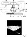
- FIG. 5Another example of a structure treated in accordance with an embodiment of the invention is shown in FIG. 5 , where a 550 ⁇ m SX protection layer is deposited on a part made of SX turbine material.
- a subsequent re-melting stepre-melts the surface layer of the deposit and leads to a very smooth surface finish and improved quality of the microstructure.
Landscapes
- Engineering & Computer Science (AREA)
- Chemical & Material Sciences (AREA)
- Physics & Mathematics (AREA)
- Optics & Photonics (AREA)
- Mechanical Engineering (AREA)
- Plasma & Fusion (AREA)
- Materials Engineering (AREA)
- Metallurgy (AREA)
- Organic Chemistry (AREA)
- Chemical Kinetics & Catalysis (AREA)
- Crystallography & Structural Chemistry (AREA)
- Electromagnetism (AREA)
- Inorganic Chemistry (AREA)
- General Engineering & Computer Science (AREA)
- Laser Beam Processing (AREA)
- Coating By Spraying Or Casting (AREA)
- Other Surface Treatments For Metallic Materials (AREA)
Abstract
Description
Claims (19)
Applications Claiming Priority (3)
| Application Number | Priority Date | Filing Date | Title |
|---|---|---|---|
| EP02405126.0 | 2002-02-20 | ||
| EP02405126AEP1340583A1 (en) | 2002-02-20 | 2002-02-20 | Method of controlled remelting of or laser metal forming on the surface of an article |
| PCT/CH2003/000098WO2003070414A1 (en) | 2002-02-20 | 2003-02-10 | Method of controlled remelting of or laser metal forming on the surface of an article |
Related Parent Applications (1)
| Application Number | Title | Priority Date | Filing Date |
|---|---|---|---|
| PCT/CH2003/000098ContinuationWO2003070414A1 (en) | 2002-02-20 | 2003-02-10 | Method of controlled remelting of or laser metal forming on the surface of an article |
Publications (2)
| Publication Number | Publication Date |
|---|---|
| US20050040147A1 US20050040147A1 (en) | 2005-02-24 |
| US7586061B2true US7586061B2 (en) | 2009-09-08 |
Family
ID=27675796
Family Applications (1)
| Application Number | Title | Priority Date | Filing Date |
|---|---|---|---|
| US10/920,715Expired - Fee RelatedUS7586061B2 (en) | 2002-02-20 | 2004-08-18 | Method of controlled remelting of or laser metal forming on the surface of an article |
Country Status (7)
| Country | Link |
|---|---|
| US (1) | US7586061B2 (en) |
| EP (2) | EP1340583A1 (en) |
| AT (1) | ATE357990T1 (en) |
| AU (1) | AU2003202401A1 (en) |
| CA (1) | CA2476290C (en) |
| DE (1) | DE60312826T2 (en) |
| WO (1) | WO2003070414A1 (en) |
Cited By (23)
| Publication number | Priority date | Publication date | Assignee | Title |
|---|---|---|---|---|
| US20080260964A1 (en)* | 2007-04-17 | 2008-10-23 | Vijayavel Bagavath-Singh | Vision system and method for direct-metal-deposition (dmd) tool-path generation |
| US20110103967A1 (en)* | 2009-11-02 | 2011-05-05 | Alstom Technology Ltd | Abrasive single-crystal turbine blade |
| US20110103968A1 (en)* | 2009-11-02 | 2011-05-05 | Alstom Technology Ltd | Wear-resistant and oxidation-resistant turbine blade |
| US20110135952A1 (en)* | 2009-12-04 | 2011-06-09 | Honeywell International Inc. | Turbine components for engines and methods of fabricating the same |
| US20120125898A1 (en)* | 2010-11-24 | 2012-05-24 | Sungwoo Hitech Co., Ltd. | Laser welding device for roll forming system and control method thereof |
| US20120138258A1 (en)* | 2009-04-24 | 2012-06-07 | Volvo Aero Corporation | method for manufacturing an engine component |
| US20120177810A1 (en)* | 2010-06-14 | 2012-07-12 | The Regents Of The University Of Michigan | In-situ identification and control of microstructures produced by phase transformation of a material |
| US20140154088A1 (en)* | 2012-12-01 | 2014-06-05 | Alstom Technology Ltd. | Method for manufacturing a metallic component by additive laser manufacturing |
| US20140202997A1 (en)* | 2013-01-24 | 2014-07-24 | Wisconsin Alumni Research Foundation | Reducing surface asperities |
| US20150174702A1 (en)* | 2012-08-08 | 2015-06-25 | Nippon Steel & Sumitomo Metal Corporation | Method of welding overlapped portion, method of manufacturing overlap-welded member, overlap-welded member, and automotive part |
| US20170008124A1 (en)* | 2014-02-06 | 2017-01-12 | Nippon Steel & Sumitomo Metal Corporation | Lap welding method, lap joint, production method of lap joint, and an automobile part |
| US20170014953A1 (en)* | 2015-07-14 | 2017-01-19 | Toyota Jidosha Kabushiki Kaisha | Method of determining quality of cladding layer and laser build-up apparatus |
| US9566665B2 (en)* | 2013-03-13 | 2017-02-14 | Rolls-Royce Corporation | Variable working distance for laser deposition |
| US9925715B2 (en) | 2014-06-30 | 2018-03-27 | General Electric Company | Systems and methods for monitoring a melt pool using a dedicated scanning device |
| US20180193959A1 (en)* | 2017-01-12 | 2018-07-12 | Caterpillar Inc. | Systems and methods for calibrating additive manufacturing operations based on energy density |
| US10372110B2 (en) | 2016-06-17 | 2019-08-06 | Hamilton Sundstrand Corporation | Controlled thin wall thickness of heat exchangers through modeling of additive manufacturing process |
| US10471547B2 (en) | 2012-12-21 | 2019-11-12 | European Space Agency | Additive manufacturing method using focused light heating source |
| US20190381604A1 (en)* | 2018-06-13 | 2019-12-19 | General Electric Company | Systems and methods for additive manufacturing |
| US20190381605A1 (en)* | 2018-06-13 | 2019-12-19 | General Electric Company | Systems and methods for finishing additive manufacturing faces with different orientations |
| US10722946B2 (en) | 2016-04-25 | 2020-07-28 | Thomas Strangman | Methods of fabricating turbine engine components |
| WO2020191263A1 (en)* | 2019-03-21 | 2020-09-24 | General Electric Company | In-situ monitoring system assisted material and parameter development for additive manufacturing |
| US20210121982A1 (en)* | 2019-10-23 | 2021-04-29 | Denso Corporation | Joining structure |
| US11162364B2 (en) | 2015-04-21 | 2021-11-02 | MTU Aero Engines AG | Repair of monocrystalline flow channel segments by monocrystalline remelting |
Families Citing this family (71)
| Publication number | Priority date | Publication date | Assignee | Title |
|---|---|---|---|---|
| EP1340583A1 (en) | 2002-02-20 | 2003-09-03 | ALSTOM (Switzerland) Ltd | Method of controlled remelting of or laser metal forming on the surface of an article |
| US7020539B1 (en) | 2002-10-01 | 2006-03-28 | Southern Methodist University | System and method for fabricating or repairing a part |
| US6995334B1 (en)* | 2003-08-25 | 2006-02-07 | Southern Methodist University | System and method for controlling the size of the molten pool in laser-based additive manufacturing |
| DE102004018699A1 (en)* | 2004-04-17 | 2005-11-03 | Mtu Aero Engines Gmbh | Method and apparatus for laser welding of superalloy components |
| FR2874624B1 (en)* | 2004-08-30 | 2007-04-20 | Snecma Moteurs Sa | METHOD FOR RECHARGING A MONOCRYSTALLINE OR DIRECTED SOLIDIFICATION METAL PIECE |
| DE102004042492A1 (en)* | 2004-08-31 | 2006-03-09 | WINKLER + DüNNEBIER AG | Method and device for producing a cutting or embossing roll by means of laser deposition welding |
| GB0420578D0 (en)* | 2004-09-16 | 2004-10-20 | Rolls Royce Plc | Forming structures by laser deposition |
| EP1852519B1 (en)* | 2006-05-05 | 2013-08-28 | Sulzer Metco AG (Switzerland) | Method for manufacturing a coating |
| US7951412B2 (en)* | 2006-06-07 | 2011-05-31 | Medicinelodge Inc. | Laser based metal deposition (LBMD) of antimicrobials to implant surfaces |
| US8257049B2 (en)* | 2008-04-25 | 2012-09-04 | Caterpillar Inc. | Process for building up an edge of a machine component, and machine component remanufacturing strategy |
| RU2466841C2 (en)* | 2008-05-29 | 2012-11-20 | Сименс Акциенгезелльшафт | Method and device for welding parts from heat-resistant alloys |
| US8505414B2 (en)* | 2008-06-23 | 2013-08-13 | Stanley Black & Decker, Inc. | Method of manufacturing a blade |
| DE102009004661A1 (en)* | 2009-01-12 | 2010-07-15 | Rolls-Royce Deutschland Ltd & Co Kg | Apparatus for repairing the blades of BLISK drums by means of laser beam welding |
| DE102009049518A1 (en) | 2009-10-15 | 2011-04-21 | Fraunhofer-Gesellschaft zur Förderung der angewandten Forschung e.V. | Method and device for welding workpieces made of heat-resistant superalloys |
| DE102009051823A1 (en)* | 2009-11-04 | 2011-05-05 | Fraunhofer-Gesellschaft zur Förderung der angewandten Forschung e.V. | Single-crystal welding of directionally solidified materials |
| EP2322314A1 (en)* | 2009-11-16 | 2011-05-18 | Fraunhofer-Gesellschaft zur Förderung der angewandten Forschung e.V. | Monocrystalline welding of directionally fixed materials |
| DE102010018686B4 (en)* | 2010-04-22 | 2017-08-17 | Fraunhofer-Gesellschaft zur Förderung der angewandten Forschung e.V. | Apparatus and method for laser cladding with powdered filler material |
| US8769833B2 (en) | 2010-09-10 | 2014-07-08 | Stanley Black & Decker, Inc. | Utility knife blade |
| CN103180490A (en)* | 2010-11-02 | 2013-06-26 | 日本碍子株式会社 | Crystal production method |
| US20120181255A1 (en)* | 2011-01-13 | 2012-07-19 | Bruck Gerald J | Flux enhanced high energy density welding |
| EP2522454A1 (en) | 2011-05-09 | 2012-11-14 | Siemens Aktiengesellschaft | Monocrystalline welding of directionally fixed materials |
| US9050674B2 (en)* | 2012-08-03 | 2015-06-09 | Lincoln Global, Inc. | Method and system of edging cladding operation |
| CN102794565B (en)* | 2012-09-04 | 2015-01-21 | 徐州工程学院 | LabView-based real-time monitoring system for laser cladding/laser re-melting process temperature field |
| JP6342912B2 (en)* | 2012-11-08 | 2018-06-13 | ディーディーエム システムズ, インコーポレイテッド | Additive manufacturing and repair of metal components |
| EP2756915A1 (en)* | 2013-01-18 | 2014-07-23 | Siemens Aktiengesellschaft | Build-up welding with previous remelting |
| EP2756912A1 (en)* | 2013-01-18 | 2014-07-23 | Siemens Aktiengesellschaft | Remelting for build-up welding |
| EP2762262A1 (en)* | 2013-02-01 | 2014-08-06 | Siemens Aktiengesellschaft | Welding process with adjustable welding power depending on the thickness |
| SG11201507650UA (en) | 2013-03-15 | 2015-10-29 | Rolls Royce Corp | Repair of gas turbine engine components |
| EP2789597B1 (en)* | 2013-04-12 | 2017-11-15 | Ansaldo Energia IP UK Limited | Method for obtaining a configuration for joining a ceramic thermal insulating material to a metallic structure |
| US9415438B2 (en) | 2013-04-19 | 2016-08-16 | United Technologies Corporation | Method for forming single crystal parts using additive manufacturing and remelt |
| DE102013226298A1 (en)* | 2013-12-17 | 2015-06-18 | MTU Aero Engines AG | Exposure to generative production |
| US20170284208A1 (en) | 2014-01-21 | 2017-10-05 | United Technologies Corporation | Method for forming single crystal components using additive manufacturing and re-melt |
| DE102014204347A1 (en)* | 2014-03-10 | 2015-09-10 | Siemens Aktiengesellschaft | Spark plasma sintering with improved joining zone strength |
| DE102014208435A1 (en)* | 2014-05-06 | 2015-11-12 | Siemens Aktiengesellschaft | Arrangement and method for layering a job layer |
| US10069271B2 (en) | 2014-06-02 | 2018-09-04 | Nlight, Inc. | Scalable high power fiber laser |
| US10618131B2 (en) | 2014-06-05 | 2020-04-14 | Nlight, Inc. | Laser patterning skew correction |
| CN106715036B (en)* | 2014-08-26 | 2019-12-10 | 密执安州立大学董事会 | Apparatus and method for direct writing of single crystal superalloys and metals |
| US9573224B2 (en) | 2014-09-02 | 2017-02-21 | Product Innovation & Engineering, LLC | System and method for determining beam power level along an additive deposition path |
| US9757902B2 (en) | 2014-09-02 | 2017-09-12 | Product Innovation and Engineering L.L.C. | Additive layering method using improved build description |
| DE102014222266A1 (en)* | 2014-10-31 | 2016-05-04 | Siemens Aktiengesellschaft | Remelting and subsequent build-up welding and component |
| US10632566B2 (en) | 2014-12-02 | 2020-04-28 | Product Innovation and Engineering L.L.C. | System and method for controlling the input energy from an energy point source during metal processing |
| EP3029113B1 (en) | 2014-12-05 | 2018-03-07 | Ansaldo Energia Switzerland AG | Abrasive coated substrate and method for manufacturing thereof |
| US9837783B2 (en) | 2015-01-26 | 2017-12-05 | Nlight, Inc. | High-power, single-mode fiber sources |
| US10050404B2 (en) | 2015-03-26 | 2018-08-14 | Nlight, Inc. | Fiber source with cascaded gain stages and/or multimode delivery fiber with low splice loss |
| US10520671B2 (en) | 2015-07-08 | 2019-12-31 | Nlight, Inc. | Fiber with depressed central index for increased beam parameter product |
| US11179807B2 (en) | 2015-11-23 | 2021-11-23 | Nlight, Inc. | Fine-scale temporal control for laser material processing |
| WO2017091505A1 (en) | 2015-11-23 | 2017-06-01 | Nlight, Inc. | Fine-scale temporal control for laser material processing |
| GB201600645D0 (en)* | 2016-01-13 | 2016-02-24 | Rolls Royce Plc | Improvements in additive layer manufacturing methods |
| SG10201700339YA (en) | 2016-02-29 | 2017-09-28 | Rolls Royce Corp | Directed energy deposition for processing gas turbine engine components |
| US10730785B2 (en) | 2016-09-29 | 2020-08-04 | Nlight, Inc. | Optical fiber bending mechanisms |
| US10673198B2 (en) | 2016-09-29 | 2020-06-02 | Nlight, Inc. | Fiber-coupled laser with time varying beam characteristics |
| US10673197B2 (en) | 2016-09-29 | 2020-06-02 | Nlight, Inc. | Fiber-based optical modulator |
| CN109791252B (en) | 2016-09-29 | 2021-06-29 | 恩耐公司 | Adjustable beam characteristics |
| US10673199B2 (en) | 2016-09-29 | 2020-06-02 | Nlight, Inc. | Fiber-based saturable absorber |
| US10126119B2 (en)* | 2017-01-17 | 2018-11-13 | General Electric Company | Methods of forming a passive strain indicator on a preexisting component |
| US10478922B2 (en)* | 2017-04-10 | 2019-11-19 | GM Global Technology Operations LLC | Wire-based additive manufacturing system and method |
| EP3406373B1 (en)* | 2017-05-22 | 2021-12-22 | nLIGHT, Inc. | Fine-scale temporal control for laser material processing |
| US10665504B2 (en) | 2017-07-28 | 2020-05-26 | Veeco Instruments Inc. | Laser-based systems and methods for melt-processing of metal layers in semiconductor manufacturing |
| US10888956B2 (en)* | 2018-06-15 | 2021-01-12 | Lawrence Livermore National Security, Llc | System and method for grain refinement and general control of grain morphology in laser additive manufacturing |
| CN109351978B (en)* | 2018-12-11 | 2020-11-03 | 苏州大学 | A method of laser cladding and stacking horizontal ribs on unequal height sections |
| DE102019207421B4 (en)* | 2019-05-21 | 2023-05-17 | Fraunhofer-Gesellschaft zur Förderung der angewandten Forschung e.V. | Process for smoothing a surface of a component by processing with energetic radiation |
| DE102020000078B3 (en)* | 2020-01-07 | 2021-06-24 | Hochschule Mittweida (Fh) | Method for smoothing at least one area of a surface of a body and using a laser operated in burst mode for smoothing |
| US11980938B2 (en) | 2020-11-24 | 2024-05-14 | Rolls-Royce Corporation | Bladed disk repair process with shield |
| US11629412B2 (en) | 2020-12-16 | 2023-04-18 | Rolls-Royce Corporation | Cold spray deposited masking layer |
| US11839915B2 (en) | 2021-01-20 | 2023-12-12 | Product Innovation and Engineering LLC | System and method for determining beam power level along an additive deposition path |
| CN113172242B (en)* | 2021-04-27 | 2021-12-28 | 武汉科技大学 | A kind of real-time monitoring device and realization method of selective laser melting forming |
| JP7435543B2 (en)* | 2021-05-28 | 2024-02-21 | トヨタ自動車株式会社 | Laser welding system and laser welding control method |
| CN113566711B (en)* | 2021-09-23 | 2021-12-07 | 四川国芯通智能科技有限公司 | Method for determining repair welding position |
| CN114505496A (en)* | 2022-02-11 | 2022-05-17 | 北京航空航天大学 | A method for controlling the directional growth of alloy grains during laser additive manufacturing |
| CN115505922B (en)* | 2022-09-05 | 2024-09-03 | 北京航空航天大学 | Bottom epitaxial growth control method of metal additive manufacturing molten pool |
| DE102023206901A1 (en)* | 2023-07-20 | 2025-01-23 | Technische Universität Bergakademie Freiberg, Körperschaft des öffentlichen Rechts | Process for thermal processing of processing areas on surfaces of workpieces, semi-finished products or powder beds |
Citations (33)
| Publication number | Priority date | Publication date | Assignee | Title |
|---|---|---|---|---|
| US3690367A (en) | 1968-07-05 | 1972-09-12 | Anadite Inc | Apparatus for the restructuring of metals |
| US4323756A (en) | 1979-10-29 | 1982-04-06 | United Technologies Corporation | Method for fabricating articles by sequential layer deposition |
| US4555610A (en)* | 1983-09-13 | 1985-11-26 | Data Card Corporation | Laser machining system |
| US4922412A (en)* | 1986-10-09 | 1990-05-01 | The Babcock & Wilcox Company | Apparatus and method using adaptive gain scheduling |
| US4960501A (en) | 1988-01-13 | 1990-10-02 | Alcan International Limited | Electrolytic cell for the production of a metal |
| DE4005314A1 (en)* | 1990-02-20 | 1991-08-22 | Messerschmitt Boelkow Blohm | Laser micro-soldering process - with temp. control by adjusting laser output energy |
| US5071059A (en)* | 1991-03-11 | 1991-12-10 | General Motors Corporation | Method for joining single crystal turbine blade halves |
| US5142778A (en)* | 1991-03-13 | 1992-09-01 | United Technologies Corporation | Gas turbine engine component repair |
| US5155329A (en)* | 1990-01-08 | 1992-10-13 | Mitsubishi Jukogyo Kabushiki Kaisha | Monitoring method and system for laser beam welding |
| DE4126351A1 (en) | 1991-08-09 | 1993-02-11 | Fraunhofer Ges Forschung | METHOD FOR MACHINING WORKPIECE SURFACES WITH LASER RADIATION |
| EP0558870A1 (en) | 1992-03-02 | 1993-09-08 | Sulzer Innotec Ag | Free welding of metal structures casing a laser |
| DE4234342A1 (en)* | 1992-10-12 | 1994-04-14 | Fraunhofer Ges Forschung | Working materials with laser beam - using high power laser diodes, for welding, drilling, cutting, soldering and heat treating various materials |
| WO1995006540A1 (en) | 1993-09-03 | 1995-03-09 | Chromalloy Gas Turbine Corporation | Interactive laser welding at elevated temperatures of superalloy articles |
| WO1995035396A1 (en) | 1994-06-22 | 1995-12-28 | United Technologies Corporation | Nickel based alloy for repairing substrates |
| US5562842A (en)* | 1994-10-17 | 1996-10-08 | Panasonic Technologies, Inc. | Material treatment apparatus combining a laser diode and an illumination light with a video imaging system |
| EP0740977A1 (en) | 1995-05-01 | 1996-11-06 | United Technologies Corporation | Containerless method of producing crack free metallic articles |
| EP0740976A1 (en) | 1995-05-01 | 1996-11-06 | United Technologies Corporation | Method of repairing single crystal metallic articles |
| US5580471A (en)* | 1994-03-30 | 1996-12-03 | Panasonic Technologies, Inc. | Apparatus and method for material treatment and inspection using fiber-coupled laser diode |
| EP0749790A1 (en) | 1995-06-20 | 1996-12-27 | Abb Research Ltd. | Process for casting a directionally solidified article and apparatus for carrying out this process |
| US5622638A (en) | 1994-08-15 | 1997-04-22 | General Electric Company | Method for forming an environmentally resistant blade tip |
| US5659479A (en)* | 1993-10-22 | 1997-08-19 | Powerlasers Ltd. | Method and apparatus for real-time control of laser processing of materials |
| US5837960A (en) | 1995-08-14 | 1998-11-17 | The Regents Of The University Of California | Laser production of articles from powders |
| US6024792A (en) | 1997-02-24 | 2000-02-15 | Sulzer Innotec Ag | Method for producing monocrystalline structures |
| DE19853733C1 (en) | 1998-11-23 | 2000-02-24 | Fraunhofer Ges Forschung | Local heat treatment of workpiece surfaces by laser beam involves locally resolved temperature measurement on the laser spot or its direct vicinity, and control of the laser output power |
| US6046426A (en) | 1996-07-08 | 2000-04-04 | Sandia Corporation | Method and system for producing complex-shape objects |
| EP1001055A1 (en) | 1998-11-10 | 2000-05-17 | Abb Research Ltd. | Gas turbine component |
| US6122564A (en) | 1998-06-30 | 2000-09-19 | Koch; Justin | Apparatus and methods for monitoring and controlling multi-layer laser cladding |
| DE19949972C1 (en) | 1999-10-11 | 2001-02-08 | Fraunhofer Ges Forschung | Process for the manufacture of molded bodies or for the application of coatings onto workpieces comprises building up a molded body in layers or applying a coating made up of at least two individual layers |
| US6311099B1 (en) | 1997-04-18 | 2001-10-30 | Daimlerchrysler Ag | Apparatus for regulating welding parameters during laser beam welding |
| WO2003070414A1 (en) | 2002-02-20 | 2003-08-28 | Alstom Technology Ltd | Method of controlled remelting of or laser metal forming on the surface of an article |
| US6998568B2 (en)* | 2002-11-29 | 2006-02-14 | Alstom Technology Ltd | Method for fabricating, modifying or repairing of single crystal or directionally solidified articles |
| US20060081571A1 (en)* | 2002-09-06 | 2006-04-20 | Alstom Technology Ltd. | Method for controlling the microstructure of a laser metal formed hard layer |
| US7043330B2 (en)* | 2002-10-31 | 2006-05-09 | Ehsan Toyserkani | System and method for closed-loop control of laser cladding by powder injection |
- 2002
- 2002-02-20EPEP02405126Apatent/EP1340583A1/ennot_activeWithdrawn
- 2003
- 2003-02-10DEDE60312826Tpatent/DE60312826T2/ennot_activeExpired - Lifetime
- 2003-02-10ATAT03700799Tpatent/ATE357990T1/ennot_activeIP Right Cessation
- 2003-02-10WOPCT/CH2003/000098patent/WO2003070414A1/enactiveIP Right Grant
- 2003-02-10AUAU2003202401Apatent/AU2003202401A1/ennot_activeAbandoned
- 2003-02-10CACA2476290Apatent/CA2476290C/ennot_activeExpired - Fee Related
- 2003-02-10EPEP03700799Apatent/EP1476272B1/ennot_activeRevoked
- 2004
- 2004-08-18USUS10/920,715patent/US7586061B2/ennot_activeExpired - Fee Related
Patent Citations (35)
| Publication number | Priority date | Publication date | Assignee | Title |
|---|---|---|---|---|
| US3690367A (en) | 1968-07-05 | 1972-09-12 | Anadite Inc | Apparatus for the restructuring of metals |
| US4323756A (en) | 1979-10-29 | 1982-04-06 | United Technologies Corporation | Method for fabricating articles by sequential layer deposition |
| US4555610A (en)* | 1983-09-13 | 1985-11-26 | Data Card Corporation | Laser machining system |
| US4922412A (en)* | 1986-10-09 | 1990-05-01 | The Babcock & Wilcox Company | Apparatus and method using adaptive gain scheduling |
| US4960501A (en) | 1988-01-13 | 1990-10-02 | Alcan International Limited | Electrolytic cell for the production of a metal |
| US5155329A (en)* | 1990-01-08 | 1992-10-13 | Mitsubishi Jukogyo Kabushiki Kaisha | Monitoring method and system for laser beam welding |
| DE4005314A1 (en)* | 1990-02-20 | 1991-08-22 | Messerschmitt Boelkow Blohm | Laser micro-soldering process - with temp. control by adjusting laser output energy |
| US5071059A (en)* | 1991-03-11 | 1991-12-10 | General Motors Corporation | Method for joining single crystal turbine blade halves |
| US5142778A (en)* | 1991-03-13 | 1992-09-01 | United Technologies Corporation | Gas turbine engine component repair |
| DE4126351A1 (en) | 1991-08-09 | 1993-02-11 | Fraunhofer Ges Forschung | METHOD FOR MACHINING WORKPIECE SURFACES WITH LASER RADIATION |
| EP0558870A1 (en) | 1992-03-02 | 1993-09-08 | Sulzer Innotec Ag | Free welding of metal structures casing a laser |
| DE4234342A1 (en)* | 1992-10-12 | 1994-04-14 | Fraunhofer Ges Forschung | Working materials with laser beam - using high power laser diodes, for welding, drilling, cutting, soldering and heat treating various materials |
| WO1995006540A1 (en) | 1993-09-03 | 1995-03-09 | Chromalloy Gas Turbine Corporation | Interactive laser welding at elevated temperatures of superalloy articles |
| US5659479A (en)* | 1993-10-22 | 1997-08-19 | Powerlasers Ltd. | Method and apparatus for real-time control of laser processing of materials |
| US5580471A (en)* | 1994-03-30 | 1996-12-03 | Panasonic Technologies, Inc. | Apparatus and method for material treatment and inspection using fiber-coupled laser diode |
| WO1995035396A1 (en) | 1994-06-22 | 1995-12-28 | United Technologies Corporation | Nickel based alloy for repairing substrates |
| US5622638A (en) | 1994-08-15 | 1997-04-22 | General Electric Company | Method for forming an environmentally resistant blade tip |
| US5562842A (en)* | 1994-10-17 | 1996-10-08 | Panasonic Technologies, Inc. | Material treatment apparatus combining a laser diode and an illumination light with a video imaging system |
| EP0740976A1 (en) | 1995-05-01 | 1996-11-06 | United Technologies Corporation | Method of repairing single crystal metallic articles |
| EP0740977A1 (en) | 1995-05-01 | 1996-11-06 | United Technologies Corporation | Containerless method of producing crack free metallic articles |
| US5914059A (en) | 1995-05-01 | 1999-06-22 | United Technologies Corporation | Method of repairing metallic articles by energy beam deposition with reduced power density |
| EP0749790A1 (en) | 1995-06-20 | 1996-12-27 | Abb Research Ltd. | Process for casting a directionally solidified article and apparatus for carrying out this process |
| US5837960A (en) | 1995-08-14 | 1998-11-17 | The Regents Of The University Of California | Laser production of articles from powders |
| US6046426A (en) | 1996-07-08 | 2000-04-04 | Sandia Corporation | Method and system for producing complex-shape objects |
| US6024792A (en) | 1997-02-24 | 2000-02-15 | Sulzer Innotec Ag | Method for producing monocrystalline structures |
| US6311099B1 (en) | 1997-04-18 | 2001-10-30 | Daimlerchrysler Ag | Apparatus for regulating welding parameters during laser beam welding |
| US6122564A (en) | 1998-06-30 | 2000-09-19 | Koch; Justin | Apparatus and methods for monitoring and controlling multi-layer laser cladding |
| EP1001055A1 (en) | 1998-11-10 | 2000-05-17 | Abb Research Ltd. | Gas turbine component |
| US6277500B1 (en) | 1998-11-10 | 2001-08-21 | Abb Research Ltd. | Gas turbine component |
| DE19853733C1 (en) | 1998-11-23 | 2000-02-24 | Fraunhofer Ges Forschung | Local heat treatment of workpiece surfaces by laser beam involves locally resolved temperature measurement on the laser spot or its direct vicinity, and control of the laser output power |
| DE19949972C1 (en) | 1999-10-11 | 2001-02-08 | Fraunhofer Ges Forschung | Process for the manufacture of molded bodies or for the application of coatings onto workpieces comprises building up a molded body in layers or applying a coating made up of at least two individual layers |
| WO2003070414A1 (en) | 2002-02-20 | 2003-08-28 | Alstom Technology Ltd | Method of controlled remelting of or laser metal forming on the surface of an article |
| US20060081571A1 (en)* | 2002-09-06 | 2006-04-20 | Alstom Technology Ltd. | Method for controlling the microstructure of a laser metal formed hard layer |
| US7043330B2 (en)* | 2002-10-31 | 2006-05-09 | Ehsan Toyserkani | System and method for closed-loop control of laser cladding by powder injection |
| US6998568B2 (en)* | 2002-11-29 | 2006-02-14 | Alstom Technology Ltd | Method for fabricating, modifying or repairing of single crystal or directionally solidified articles |
Non-Patent Citations (7)
| Title |
|---|
| IPER from PCT/CH 03/00098 (Dec. 10, 2003). |
| Ma, Dexin, Peter R. Sahm. Einkristallerstarrung der Ni-Basis-Superlegierung SRR 99. Zeitschrift für Metallkunde 11 (1991): 869-873. |
| Mazumder et al., 2000, "Closed loop direct metal deposition: art to part", Optics and Lasers in Engineering, vol. 34, pp. 397-414.* |
| Meriaudeau et al., 1996,"Image Processing Applied to Laser Cladding Process" SPIE vol. 2789, pp. 93-103.* |
| Romer, thesis of "Modelling and Control of Laser Surface Treatment",1999, Printed by Printed by Print Partners Ipskamp, pp. i-v of preface, pp. 1-5,7-15,17-41,43-127,129-163,165-192. ISBN 90-365-1304-9.* |
| Search Report from EP 02 40 5126 (Aug. 21, 2002). |
| Search Report from PCT/CH 03/00098 (Apr. 29, 2003). |
Cited By (44)
| Publication number | Priority date | Publication date | Assignee | Title |
|---|---|---|---|---|
| US20080260964A1 (en)* | 2007-04-17 | 2008-10-23 | Vijayavel Bagavath-Singh | Vision system and method for direct-metal-deposition (dmd) tool-path generation |
| US20120138258A1 (en)* | 2009-04-24 | 2012-06-07 | Volvo Aero Corporation | method for manufacturing an engine component |
| US8944139B2 (en)* | 2009-04-24 | 2015-02-03 | Volvo Aero Corporation | Method for manufacturing an engine component |
| US8740572B2 (en) | 2009-11-02 | 2014-06-03 | Alstom Technology Ltd. | Wear-resistant and oxidation-resistant turbine blade |
| US20110103967A1 (en)* | 2009-11-02 | 2011-05-05 | Alstom Technology Ltd | Abrasive single-crystal turbine blade |
| US20110103968A1 (en)* | 2009-11-02 | 2011-05-05 | Alstom Technology Ltd | Wear-resistant and oxidation-resistant turbine blade |
| US8647073B2 (en) | 2009-11-02 | 2014-02-11 | Alstom Technology Ltd. | Abrasive single-crystal turbine blade |
| US20110135952A1 (en)* | 2009-12-04 | 2011-06-09 | Honeywell International Inc. | Turbine components for engines and methods of fabricating the same |
| US8728388B2 (en) | 2009-12-04 | 2014-05-20 | Honeywell International Inc. | Method of fabricating turbine components for engines |
| US9752988B2 (en)* | 2010-06-14 | 2017-09-05 | The Regents Of The University Of Michigan | In-situ identification and control of microstructures produced by phase transformation of a material |
| US10254231B2 (en) | 2010-06-14 | 2019-04-09 | The Regents Of The University Of Michigan | In-situ identification and control of microstructures produced by phase transformation of a material |
| US20120177810A1 (en)* | 2010-06-14 | 2012-07-12 | The Regents Of The University Of Michigan | In-situ identification and control of microstructures produced by phase transformation of a material |
| US20120125898A1 (en)* | 2010-11-24 | 2012-05-24 | Sungwoo Hitech Co., Ltd. | Laser welding device for roll forming system and control method thereof |
| US8847107B2 (en)* | 2010-11-24 | 2014-09-30 | Sungwoo Hitech Co., Ltd. | Laser welding device for roll forming system and control method thereof |
| US20150174702A1 (en)* | 2012-08-08 | 2015-06-25 | Nippon Steel & Sumitomo Metal Corporation | Method of welding overlapped portion, method of manufacturing overlap-welded member, overlap-welded member, and automotive part |
| US10549388B2 (en)* | 2012-08-08 | 2020-02-04 | Nippon Steel Corporation | Method of welding overlapped portion, method of manufacturing overlap-welded member, overlap-welded member, and automotive part |
| US20140154088A1 (en)* | 2012-12-01 | 2014-06-05 | Alstom Technology Ltd. | Method for manufacturing a metallic component by additive laser manufacturing |
| US10471547B2 (en) | 2012-12-21 | 2019-11-12 | European Space Agency | Additive manufacturing method using focused light heating source |
| US11389902B2 (en)* | 2013-01-24 | 2022-07-19 | Wisconsin Alumni Research Foundation | Reducing surface asperities |
| US20140202997A1 (en)* | 2013-01-24 | 2014-07-24 | Wisconsin Alumni Research Foundation | Reducing surface asperities |
| US10315275B2 (en)* | 2013-01-24 | 2019-06-11 | Wisconsin Alumni Research Foundation | Reducing surface asperities |
| US9566665B2 (en)* | 2013-03-13 | 2017-02-14 | Rolls-Royce Corporation | Variable working distance for laser deposition |
| US20170008124A1 (en)* | 2014-02-06 | 2017-01-12 | Nippon Steel & Sumitomo Metal Corporation | Lap welding method, lap joint, production method of lap joint, and an automobile part |
| US10589380B2 (en)* | 2014-02-06 | 2020-03-17 | Nippon Steel Corporation | Lap welding method, lap joint, production method of lap joint, and an automobile part |
| US9925715B2 (en) | 2014-06-30 | 2018-03-27 | General Electric Company | Systems and methods for monitoring a melt pool using a dedicated scanning device |
| US10464262B2 (en) | 2014-06-30 | 2019-11-05 | General Electric Company | Systems and methods for monitoring a melt pool using a dedicated scanning device |
| US11162364B2 (en) | 2015-04-21 | 2021-11-02 | MTU Aero Engines AG | Repair of monocrystalline flow channel segments by monocrystalline remelting |
| US10286495B2 (en)* | 2015-07-14 | 2019-05-14 | Toyota Jidosha Kabushiki Kaisha | Method of determining quality of cladding layer and laser build-up apparatus |
| US20170014953A1 (en)* | 2015-07-14 | 2017-01-19 | Toyota Jidosha Kabushiki Kaisha | Method of determining quality of cladding layer and laser build-up apparatus |
| US10722946B2 (en) | 2016-04-25 | 2020-07-28 | Thomas Strangman | Methods of fabricating turbine engine components |
| US10372110B2 (en) | 2016-06-17 | 2019-08-06 | Hamilton Sundstrand Corporation | Controlled thin wall thickness of heat exchangers through modeling of additive manufacturing process |
| US20180193959A1 (en)* | 2017-01-12 | 2018-07-12 | Caterpillar Inc. | Systems and methods for calibrating additive manufacturing operations based on energy density |
| US10549519B2 (en)* | 2017-01-12 | 2020-02-04 | Caterpillar Inc. | Systems and methods for calibrating additive manufacturing operations based on energy density |
| US11072039B2 (en)* | 2018-06-13 | 2021-07-27 | General Electric Company | Systems and methods for additive manufacturing |
| US10919115B2 (en)* | 2018-06-13 | 2021-02-16 | General Electric Company | Systems and methods for finishing additive manufacturing faces with different orientations |
| US20190381605A1 (en)* | 2018-06-13 | 2019-12-19 | General Electric Company | Systems and methods for finishing additive manufacturing faces with different orientations |
| US20210323093A1 (en)* | 2018-06-13 | 2021-10-21 | General Electric Company | Systems and methods for additive manufacturing |
| US20190381604A1 (en)* | 2018-06-13 | 2019-12-19 | General Electric Company | Systems and methods for additive manufacturing |
| US11911848B2 (en)* | 2018-06-13 | 2024-02-27 | General Electric Company | Systems and methods for additive manufacturing |
| WO2020191263A1 (en)* | 2019-03-21 | 2020-09-24 | General Electric Company | In-situ monitoring system assisted material and parameter development for additive manufacturing |
| US11472115B2 (en) | 2019-03-21 | 2022-10-18 | General Electric Company | In-situ monitoring system assisted material and parameter development for additive manufacturing |
| US12023860B2 (en) | 2019-03-21 | 2024-07-02 | General Electric Company | In-situ monitoring system assisted material and parameter development for additive manufacturing |
| US20210121982A1 (en)* | 2019-10-23 | 2021-04-29 | Denso Corporation | Joining structure |
| US11897053B2 (en)* | 2019-10-23 | 2024-02-13 | Denso Corporation | Joining structure |
Also Published As
| Publication number | Publication date |
|---|---|
| CA2476290A1 (en) | 2003-08-28 |
| EP1340583A1 (en) | 2003-09-03 |
| AU2003202401A1 (en) | 2003-09-09 |
| EP1476272B1 (en) | 2007-03-28 |
| ATE357990T1 (en) | 2007-04-15 |
| WO2003070414A1 (en) | 2003-08-28 |
| CA2476290C (en) | 2011-01-25 |
| EP1476272A1 (en) | 2004-11-17 |
| DE60312826T2 (en) | 2008-01-24 |
| US20050040147A1 (en) | 2005-02-24 |
| DE60312826D1 (en) | 2007-05-10 |
Similar Documents
| Publication | Publication Date | Title |
|---|---|---|
| US7586061B2 (en) | Method of controlled remelting of or laser metal forming on the surface of an article | |
| US7705264B2 (en) | Method for controlling the microstructure of a laser metal formed hard layer | |
| US6998568B2 (en) | Method for fabricating, modifying or repairing of single crystal or directionally solidified articles | |
| US6103402A (en) | Crack free metallic articles | |
| US6024792A (en) | Method for producing monocrystalline structures | |
| EP0740976B1 (en) | Method of repairing single crystal metallic articles | |
| EP3096905B1 (en) | A method of additive manufacturing utilizing an epitaxy process | |
| JP6022679B2 (en) | Repair of directionally solidified alloys | |
| US20050067065A1 (en) | Method of removing casting defects | |
| GB2453945A (en) | Apparatus for Additive Manufacture Welding | |
| CN114502303A (en) | Powder bed melting additive manufacturing method and device | |
| JP2005522342A (en) | Method for producing single crystal structure | |
| US7744967B2 (en) | Process for resurfacing a monocrystalline or directionally solidified metallic piece | |
| GB2453943A (en) | Method and apparatus for welding | |
| PL197479B1 (en) | Method for producing a surface−alloyed cylindrical, partially cylindrical or hollow cylindrical component and a device for carrying out said method | |
| JP5941375B2 (en) | Laser overlay welding apparatus and manufacturing method of overlay weld parts | |
| US6902617B2 (en) | Method of welding single crystals |
Legal Events
| Date | Code | Title | Description |
|---|---|---|---|
| AS | Assignment | Owner name:ALSTOM TECHNOLOGY LTD, SWITZERLAND Free format text:ASSIGNMENT OF ASSIGNORS INTEREST;ASSIGNORS:HOEBEL, MATTHIAS;FEHRMANN, BERND;REEL/FRAME:015399/0977;SIGNING DATES FROM 20040910 TO 20040913 | |
| STCF | Information on status: patent grant | Free format text:PATENTED CASE | |
| FPAY | Fee payment | Year of fee payment:4 | |
| AS | Assignment | Owner name:GENERAL ELECTRIC TECHNOLOGY GMBH, SWITZERLAND Free format text:CHANGE OF NAME;ASSIGNOR:ALSTOM TECHNOLOGY LTD;REEL/FRAME:038216/0193 Effective date:20151102 | |
| AS | Assignment | Owner name:ANSALDO ENERGIA IP UK LIMITED, GREAT BRITAIN Free format text:ASSIGNMENT OF ASSIGNORS INTEREST;ASSIGNOR:GENERAL ELECTRIC TECHNOLOGY GMBH;REEL/FRAME:041731/0626 Effective date:20170109 | |
| FPAY | Fee payment | Year of fee payment:8 | |
| FEPP | Fee payment procedure | Free format text:MAINTENANCE FEE REMINDER MAILED (ORIGINAL EVENT CODE: REM.); ENTITY STATUS OF PATENT OWNER: LARGE ENTITY | |
| LAPS | Lapse for failure to pay maintenance fees | Free format text:PATENT EXPIRED FOR FAILURE TO PAY MAINTENANCE FEES (ORIGINAL EVENT CODE: EXP.); ENTITY STATUS OF PATENT OWNER: LARGE ENTITY | |
| STCH | Information on status: patent discontinuation | Free format text:PATENT EXPIRED DUE TO NONPAYMENT OF MAINTENANCE FEES UNDER 37 CFR 1.362 | |
| FP | Lapsed due to failure to pay maintenance fee | Effective date:20210908 |