US7585299B2 - Dorsal adjusting spinal connector assembly - Google Patents
Dorsal adjusting spinal connector assemblyDownload PDFInfo
- Publication number
- US7585299B2 US7585299B2US11/356,939US35693906AUS7585299B2US 7585299 B2US7585299 B2US 7585299B2US 35693906 AUS35693906 AUS 35693906AUS 7585299 B2US7585299 B2US 7585299B2
- Authority
- US
- United States
- Prior art keywords
- passage
- coupling body
- implant
- clamping member
- connecting portion
- Prior art date
- Legal status (The legal status is an assumption and is not a legal conclusion. Google has not performed a legal analysis and makes no representation as to the accuracy of the status listed.)
- Active, expires
Links
- 239000007943implantSubstances0.000claimsdescription93
- 230000008878couplingEffects0.000claimsdescription84
- 238000010168coupling processMethods0.000claimsdescription84
- 238000005859coupling reactionMethods0.000claimsdescription84
- 238000000034methodMethods0.000claimsdescription16
- 210000000988bone and boneAnatomy0.000claimsdescription14
- 238000005452bendingMethods0.000claimsdescription7
- 238000004891communicationMethods0.000claimsdescription5
- 230000000087stabilizing effectEffects0.000claimsdescription5
- 230000007704transitionEffects0.000claims2
- 230000000712assemblyEffects0.000description7
- 238000000429assemblyMethods0.000description7
- 230000006641stabilisationEffects0.000description4
- 238000011105stabilizationMethods0.000description4
- 238000002513implantationMethods0.000description3
- 238000002955isolationMethods0.000description3
- 238000001356surgical procedureMethods0.000description3
- 210000001519tissueAnatomy0.000description3
- 230000007246mechanismEffects0.000description2
- 230000004048modificationEffects0.000description2
- 238000012986modificationMethods0.000description2
- 230000008569processEffects0.000description2
- 230000009471actionEffects0.000description1
- 230000004075alterationEffects0.000description1
- 210000003484anatomyAnatomy0.000description1
- 238000004873anchoringMethods0.000description1
- 230000008901benefitEffects0.000description1
- 230000000694effectsEffects0.000description1
- 230000004927fusionEffects0.000description1
- 210000004705lumbosacral regionAnatomy0.000description1
- 239000000463materialSubstances0.000description1
- 238000002324minimally invasive surgeryMethods0.000description1
- 230000037361pathwayEffects0.000description1
- 230000001737promoting effectEffects0.000description1
- 230000004044responseEffects0.000description1
- 230000000717retained effectEffects0.000description1
- 210000000954sacrococcygeal regionAnatomy0.000description1
- 239000012781shape memory materialSubstances0.000description1
- 210000000115thoracic cavityAnatomy0.000description1
Images


Classifications
- A—HUMAN NECESSITIES
- A61—MEDICAL OR VETERINARY SCIENCE; HYGIENE
- A61B—DIAGNOSIS; SURGERY; IDENTIFICATION
- A61B17/00—Surgical instruments, devices or methods
- A61B17/56—Surgical instruments or methods for treatment of bones or joints; Devices specially adapted therefor
- A61B17/58—Surgical instruments or methods for treatment of bones or joints; Devices specially adapted therefor for osteosynthesis, e.g. bone plates, screws or setting implements
- A61B17/68—Internal fixation devices, including fasteners and spinal fixators, even if a part thereof projects from the skin
- A61B17/70—Spinal positioners or stabilisers, e.g. stabilisers comprising fluid filler in an implant
- A61B17/7001—Screws or hooks combined with longitudinal elements which do not contact vertebrae
- A61B17/7041—Screws or hooks combined with longitudinal elements which do not contact vertebrae with single longitudinal rod offset laterally from single row of screws or hooks
- A—HUMAN NECESSITIES
- A61—MEDICAL OR VETERINARY SCIENCE; HYGIENE
- A61B—DIAGNOSIS; SURGERY; IDENTIFICATION
- A61B17/00—Surgical instruments, devices or methods
- A61B17/56—Surgical instruments or methods for treatment of bones or joints; Devices specially adapted therefor
- A61B17/58—Surgical instruments or methods for treatment of bones or joints; Devices specially adapted therefor for osteosynthesis, e.g. bone plates, screws or setting implements
- A61B17/68—Internal fixation devices, including fasteners and spinal fixators, even if a part thereof projects from the skin
- A61B17/70—Spinal positioners or stabilisers, e.g. stabilisers comprising fluid filler in an implant
- A61B17/7001—Screws or hooks combined with longitudinal elements which do not contact vertebrae
- A61B17/7035—Screws or hooks, wherein a rod-clamping part and a bone-anchoring part can pivot relative to each other
- A61B17/7037—Screws or hooks, wherein a rod-clamping part and a bone-anchoring part can pivot relative to each other wherein pivoting is blocked when the rod is clamped
- A—HUMAN NECESSITIES
- A61—MEDICAL OR VETERINARY SCIENCE; HYGIENE
- A61B—DIAGNOSIS; SURGERY; IDENTIFICATION
- A61B17/00—Surgical instruments, devices or methods
- A61B17/56—Surgical instruments or methods for treatment of bones or joints; Devices specially adapted therefor
- A61B17/58—Surgical instruments or methods for treatment of bones or joints; Devices specially adapted therefor for osteosynthesis, e.g. bone plates, screws or setting implements
- A61B17/68—Internal fixation devices, including fasteners and spinal fixators, even if a part thereof projects from the skin
- A61B17/70—Spinal positioners or stabilisers, e.g. stabilisers comprising fluid filler in an implant
- A61B17/7001—Screws or hooks combined with longitudinal elements which do not contact vertebrae
- A61B17/7035—Screws or hooks, wherein a rod-clamping part and a bone-anchoring part can pivot relative to each other
- A61B17/704—Screws or hooks, wherein a rod-clamping part and a bone-anchoring part can pivot relative to each other the longitudinal element passing through a ball-joint in the screw head
- A—HUMAN NECESSITIES
- A61—MEDICAL OR VETERINARY SCIENCE; HYGIENE
- A61B—DIAGNOSIS; SURGERY; IDENTIFICATION
- A61B17/00—Surgical instruments, devices or methods
- A61B17/56—Surgical instruments or methods for treatment of bones or joints; Devices specially adapted therefor
- A61B17/58—Surgical instruments or methods for treatment of bones or joints; Devices specially adapted therefor for osteosynthesis, e.g. bone plates, screws or setting implements
- A61B17/60—Surgical instruments or methods for treatment of bones or joints; Devices specially adapted therefor for osteosynthesis, e.g. bone plates, screws or setting implements for external osteosynthesis, e.g. distractors, contractors
- A61B17/64—Devices extending alongside the bones to be positioned
- A61B17/6466—Devices extending alongside the bones to be positioned with pin-clamps movable along a solid connecting rod
Definitions
- Spinal implantscan be engaged to or along one or more vertebrae of the spinal column for the treatment of various spinal conditions.
- Fastenerscan be provided to secure the implant to a particular location along the spinal column.
- the implantscan be provided to stabilize the spinal column for treatment, either by fixing the spinal column or by permitting at least some motion of the stabilized motion segments.
- Multi-axial and uni-axial screwshave been employed for securing elongated implants, such as rods or plates, along one or more motion segments of the spinal column.
- elongated implantssuch as rods or plates
- Such fastenerscan comprise many components or parts that make placement and manipulation of the fastener and the elongated implant cumbersome during surgery to achieve the desired position relative to the spinal anatomy.
- Fasteners that facilitate securement of the elongated implant in a desired positioning along the spinal columncan enhance spinal stabilization procedures.
- a connector assemblyincludes a coupling body for securing an elongate member to an implant engaged to the spinal column.
- the elongate memberis offset to one side of and transversely oriented to the implant.
- the coupling bodyincludes a first passage for receiving the implant, a second passage for receiving the elongate member, and a clamping member positioned about the elongate member.
- the coupling assemblyalso includes an engaging member that engages the coupling body and contacts the clamping member to clampingly engage the elongate member with the clamping member while forcing the coupling body positioned about the implant into engagement with the implant.
- a system for stabilizing a bony segmentincludes an elongate member positionable along the bony segment, an implant including a proximal portion and a distal portion engageable to the bony segment with the proximal portion in a transverse orientation to the elongate member, and a connector assembly for connecting the elongate member to the implant.
- the connector assemblyincludes a coupling body, an engaging member and a clamping member.
- the coupling bodyhas a pair of arms extending alongside one another between a free end and an opposite end.
- a connecting portionextends between the pair of arms at the opposite ends and defines a first passage receiving the proximal portion of the implant therethrough.
- the pair of armsdefines a second passage receiving the elongate member therethrough in the transverse orientation.
- the clamping membercan be positioned about the elongate member in the second passage, and the engaging member can be engaged to the first arm in a first position.
- the engaging memberis movable toward the clamping member from the first position to contact the clamping member to clampingly engage the clamping member to the elongate member while flexing the coupling body about the connecting portion to engage the coupling body to the proximal portion of the implant.
- a system for stabilizing a bony segmentincludes an elongate member positionable along the bony segment, an implant including a proximal portion and a distal portion engageable to the bony segment with the proximal portion in a transverse orientation to the elongate member, and a connector assembly for connecting the elongate member to the implant.
- the connector assemblyincludes a coupling body, an engaging member and a clamping member.
- the coupling bodyhas a connecting portion extending between a pair of arms. The arms extend from the connecting portion alongside one another and form a gap therebetween.
- the connecting portiondefines a first passage receiving the proximal portion of the implant therethrough and the pair of arms defines a second passage receiving the elongate member therethrough in the transverse orientation.
- the clamping memberis positioned about the elongate member in the second passage, and an engaging member is engaged to the first arm in a first position.
- the coupling bodyis configured to move the first arm along the engaging member and away from the clamping member as the engaging member is moved from the first position to contact the clamping member and clampingly engage the clamping member to the elongate member. Movement of the first arm bends the coupling body about the connecting portion and frictionally engages the coupling body to the proximal portion of the implant in the first passage.
- a method for coupling an elongate member to an implant engageable to a spinal columncomprises: engaging the implant to a vertebra of the spinal column; positioning an elongate member along the spinal column in a transverse orientation to the implant; positioning a clamping member about the elongate member; positioning a proximal portion of the implant in a first passage of a coupling body; positioning the clamping member in a second passage of the coupling body; engaging an engaging member to the coupling body; contacting the engaging member to the clamping member to clamp the clamping member about the elongate member while simultaneously bending the coupling body with the engaging member to clampingly engage the coupling body to the proximal portion of the implant in the first passage.
- FIG. 1is a sectional view of a connector assembly.
- FIG. 2is a perspective view of a coupling body of the connecting assembly of FIG. 1 .
- FIG. 3is a section view of the coupling body of FIG. 2 looking in the same direction as FIG. 1 but with the clamping member and engaging member removed.
- FIG. 4is a section view along line 4 - 4 of FIG. 3 .
- FIG. 5is an elevation view of a clamping member.
- FIG. 6is a section view through line 6 - 6 of FIG. 5 .
- FIG. 7is an elevation view of an engaging member.
- FIG. 8is a section view through line 8 - 8 of FIG. 7 .
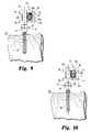
- FIG. 9is an elevation view of an implant engaged to a vertebral body (shown diagrammatically) and a connector assembly (with engaging member removed) positioned about the implant with an elongate member shown in section extending through the connector assembly transversely to and laterally offset from the implant.
- FIG. 10is the connector assembly, implant and elongate member of FIG. 9 when the clamping member is clampingly engaged to the elongate member and the coupling body is flexed to clampingly engage the implant.
- FIG. 1shows an embodiment of a connector assembly 10 , and in FIGS. 9-10 an implant 12 and elongate member 13 are shown coupled to connector assembly 10 .
- Connector assembly 10is operable to connect implant 12 , such as a bone anchor, with elongate member 13 , such as a spinal rod, to form an implant system.
- Implant 12can be a bone screw or other suitable anchoring device engageable to bone or another implant.
- the implantcan include a portion for engagement with connector assembly 10 .
- Elongate member 13can be a spinal rod or other member positionable along the spinal column to maintain or assist in maintaining one or more vertebrae in a desired position.
- Connector assembly 10can include a coupling body 20 extending between implant 12 and elongate member 13 .
- Connector assembly 10can further include a clamping member 40 positioned about elongate member 13 in coupling body 20 .
- Connector assembly 10can also include an engaging member 60 engageable to coupling body 20 .
- Engaging member 60is operable to contact clamping member 40 to clampingly engage it about elongate member 13 while simultaneously flexing, deforming or otherwise manipulating coupling body 20 to engage implant 12 .
- Coupling body 20can be engaged to a proximal portion 16 of implant 12 .
- proximal portion 16can be a post, arm, or other suitable extension or portion for positioning through coupling body 20 .
- Coupling body 20can include a first passage 22 extending along a first axis 23 and a second passage 24 extending along a second axis 25 .
- First and second axes 23 , 25can extend transversely to one another.
- axes 23 , 25are orthogonally oriented relative to one another.
- Proximal portion 16 of implant 12can extend through first passage 22 in general alignment with axis 23
- elongate member 13can extend through second passage 24 in general alignment with axis 25 . Accordingly, implant 12 and elongate member 13 can be transversely oriented relative to one another with elongate member 13 laterally or medially offset to one side of implant 12 .
- Implant 12 in the illustrated embodimentis a bone screw and can include a distal shaft 18 having a thread profile therealong for engaging bone, and an enlarged head 14 between distal shaft 18 and proximal portion 16 .
- Head 14can include flats or other tool engaging features therearound to engage a driving tool to facilitate engagement of implant 12 to the underlying bone.
- Various forms for implant 12are contemplated, including threaded and non-threaded anchors, uni-planar and multi-axial pivoting arrangements. Bone engaging portions in the form of hooks, clamps, spikes, cables, interbody implants, fusion devices, non-cannulated screws, fenestrated screws, and bolts, are also contemplated, for example.
- the implantcan be connected to another implant, and/or can be a bone plate, staple, and/or cross-connector extending between spinal rods, for example.
- Elongate member 13can be structured either alone or in combination with one or more other elongate members, implants and/or connector assemblies to provide a desired stabilization effect.
- elongate member 13is a spinal rod structured to extend between at least two connector assemblies 10 secured to the spinal column with corresponding bone engaging implants.
- Elongate member 13can also extend between at least one connector assembly 10 and another implant having any type of suitable connection mechanism to secure elongate member 13 to the implant.
- Various forms for elongate member 13are contemplated, including rods, tethers, cables, wires, and plates, for example.
- Coupling body 20is shown in isolation in FIGS. 2-4 .
- Coupling body 20includes a pairs of arms 26 , selectively referred to as a first arm 26 a and a second arm 26 b .
- Arms 26 a , 26 bextend from adjacent free ends to opposite ends that are interconnected by a connecting portion 28 extending therebetween.
- Connecting portion 28includes a shape that defines first passage 22 therethrough in a direction that extends transversely to arms 26 a , 26 b .
- first and second arms 26 a , 26 bdefine respective portions of second passage 24 therebetween.
- Coupling body 20includes a gap 38 extending along an axis 29 that is located between arms 26 a , 26 b .
- Gap axis 29is transversely oriented to longitudinal axis 25 and to longitudinal axis 23 .
- Gap 38includes an intermediate portion 38 a that extends between first and second passages 22 and 24 , and an outer portion 38 b that extends from second passage 24 to the outer, free ends of arms 26 a , 26 b .
- Gap 38further includes an inner portion 38 c in connecting portion 28 that forms a transverse axial extension of gap 38 in the direction of axis 23 .
- the inner portion 38 cprovides a slotted arrangement that forms reliefs to facilitate flexing, bending, and deforming of coupling body 20 about connecting portion 28 , as discussed further below.
- First and second arms 26 a , 26 binclude a respective one of the concavely curved inner surface portion 39 a , 39 b defining second passage 24 .
- arms 26 a , 26 beach include a respective groove 31 a , 31 b extending about a respective one of the inner surfaces 39 a , 39 b thereof that define passage 24 .
- Each groove 31 a , 31 bincludes a respective one of the outer portions 32 a , 32 b and middle portions 33 a , 33 b extending into the respective inner surface 39 a , 39 b of first and second arm 26 a , 26 b .
- Middle portions 33 a , 33 bare each deeper than the respective adjacent outer portions 32 a , 32 b so that an edge is formed between each of the portions of grooves 31 a , 31 b and the respective adjacent portion of inner surfaces 39 a , 39 b . These edges can bite into the outer surface of clamping member 40 when clamping member 40 is pressed against one of the arms 26 a , 26 b , thereby locking clamping member 40 in position in passage 24 .
- First arm 26 aalso includes a receptacle 30 extending therethrough in communication with second passage 24 .
- Receptacle 30opens at a proximal facing surface or side 27 a of arm 26 a .
- Receptacle 30can include an internal thread profile extending therealong to threadingly engage engaging member 60 , as discussed further below. The thread profile allows advancement of engaging member 60 in a direction that is transverse to axes 25 , 29 and in the same general direction as axis 23 . Orientations of receptacle 30 that are oblique relative to axes 25 , 29 are also contemplated.
- Coupling body 20can flex about connecting portion 28 in response to movement of at least one of the arms 26 a , 26 b away from the other and widening of outer portion 38 b of gap 38 .
- connecting portion 28can deform or flex toward first passage 22 and into contact with proximal portion 16 of implant 12 to clampingly or frictionally engage implant 12 to coupling body 20 .
- Connector assembly 10includes clamping member 40 positionable about elongate member 13 .
- Clamping member 40is shown in isolation in FIGS. 5 and 6 , and in second passage 24 in FIG. 1 .
- clamping member 40can pivot in passage 24 to facilitate orienting coupling body 20 , implant 12 and elongate member 13 relative to one another.
- Clamping member 40includes a passage 42 extending therethrough to receive elongate member 13 .
- Clamping member 40can include an outer surface 46 that defines a spherical shape, and an internal wall 48 defining passage 42 .
- Internal wall 48includes a central concave portion 44 that is concavely curved and linear end portions 45 extending from central concave portion 44 .
- Clamping member 40further includes a gap 52 extending axially therealong that allows portions of the clamping member 40 to be moved toward one another by reducing gap 52 . Such movement can be facilitated by a hinge 54 formed in clamping member 40 opposite gap 52 .
- hinge 54is formed by reducing a wall thickness of clamping member 40 , providing a living or integral hinge.
- FIG. 1Other embodiments contemplate other structures for clamping about elongate member 13 , including shape memory material and material sufficiently deformable without a hinge.
- the concavely curved inner wall portion 44is spaced from elongate member 13 , allowing circumferential contact by liner end portions 45 of internal wall 48 with the elongate member 13 .
- This arrangementcan reduce binding or twisting that could be created as clamping member 40 is clamped about elongate member 13 .
- Connector assembly 10further includes engaging member 60 engageable in receptacle 30 and positionable in contact with clamping member 40 in second passage 24 as shown in FIG. 1 .
- Engaging member 60is shown in isolation in FIGS. 7-8 , and includes a proximal head portion 62 , a distal engaging portion 64 , and a distal end surface 66 .
- Head portion 62can be configured to engage a driving tool that can be positioned about head portion 62 or in an internal recess in head portion 62 (not shown).
- head portion 62includes a non-circular external shape, such as a hex-shape, to receive a driving tool thereabout.
- Distal engaging portion 64 of engaging member 60can include an externally threaded cylindrical body that threadingly engages internal threads along receptacle 30 .
- Engaging member 60also includes distal end surface 66 that is positionable into contact with clamping member 40 as engaging member 60 is threaded into receptacle 30 .
- Distal end surface 66can be concavely curved to engage clamping member 40 in form fitting engagement and facilitate rotation of engaging member 60 against clamping member 40 .
- the use of an instrument to drive engaging member 60 against clamping member 40can provide a mechanical advantage in deforming coupling body 20 by separating arms 26 a , 26 b about connecting portion 28 and also in deforming clamping member 40 about hinge 54 to close gap 52 and clampingly engage elongate member 13 .
- Engaging member 60can include a proximal break-off portion (not shown) that severs upon application of a threshold torque, although embodiments without a break-off portion are contemplated as shown.
- Engaging member 60is shown with external threads that engage the internal thread profile along receptacle 30 .
- Other configurationsare also contemplated for engagement of engaging member 60 to coupling body 20 , including multiple component members with internally and/or externally threaded portions, frictionally engaged members, shape memory members, snap fits, clamps and bayonet-type fits, for example.
- connector assembly 10can be used in surgical procedures relating to the spine.
- the surgeoncan gain access to a surgical site using any suitable technique, such as through an incision and retraction of tissue, or through minimally invasive access portals or pathways.
- One or more of the implants 12can be provided in the form of bone screws that are threadingly implanted into one or more vertebrae V 1 , such as in the pedicle in a posterior stabilization procedure.
- Proximal portion 16can extend dorsally from the pedicle.
- Coupling body 20can be positioned about clamping member 40 with clamping member 40 loosely retained in passage 24 .
- Elongate member 13can be positioned through clamping member 40 . It is contemplated that assembly of coupling body 20 with clamping member 40 and elongate member 13 can be completed prior to implantation of elongate member 13 or during implantation. In either case, elongate member 13 can be positioned along the spinal column with coupling body 20 secured thereto and arms 26 a , 26 b extending from elongate member 13 toward proximal portion 16 of implant 12 . Coupling body 20 can then be positioned over implant 12 with proximal portion 16 extending into first passage 22 .
- First passage 22can be configured to provide a close, sliding fit with proximal portion 16 .
- the orientation of elongate member 13 relative to coupling body 20can be adjusted by pivoting coupling body 20 about clamping member 40 in second passage 24 .
- Engaging member 60is positioned in receptacle 30 and threaded distally therealong in the direction of arrow 70 to contact clamping member 40 . Further advancement of engaging member 60 into receptacle 30 closes gap 52 of clamping member 40 to clampingly engage clamping member 40 about elongate member 13 .
- clamping arm 26 amoves proximally along the threaded portion of engaging member 60 as indicated by arrow 72
- clamping arm 26 bmoves or deforms in the opposite direction as indicated by arrow 74 .
- Coupling body 24also bends or flexes about connecting portion 28 , as indicated by arrows 76 , 78 , to deform or position connecting portion 28 toward first passage 22 .
- connector assembly 10allows engagement of elongate member 13 to implant 12 to maintain a low profile in the medial-lateral direction and a nearly tangential proximity of the implant 12 and elongate member 13 .
- Non-perpendicular orientations between elongate member 13 and proximal portion 16 of implant 12are possible to accommodate engagement of implant 12 with the spinal column and placement of elongate member 13 along the spinal column in various orientations relative to one another.
- a clamping action about elongate member 13 with clamping member 40 and locking engagement with coupling body 20maintains the positioning of clamping member 40 and coupling body 20 relative to one another when coupling body 12 is secured to implant 12 .
- the location of connection portion 28 along proximal portion 16 of implant 12can be adjusted, and coupling body 20 can be secured to implant 12 at any one of a number of positions along proximal portion 16 .
- elongate member 13 and one or more connector assemblies 10 and other implants discussed hereinmay be employed unilaterally.
- a second elongate member 13 and one or more connector assemblies 10 and/or other suitable connection mechanism with other implantscan be secured to the other side of the vertebral level or levels to be stabilized.
- Multiple elongate members 13 and corresponding implant/connector assemblies 10can be secured along the same side of the spinal column in either uni-lateral or bi-lateral stabilization procedures.
- the underlying boneforms a portion of a vertebral body of the spinal column.
- the underlying bonecan be a part of the anterior, oblique, antero-lateral, lateral or posterior vertebral elements, including the pedicle, spinous process, transverse processes, lamina or facet, for example.
- Applications in techniques along any portion or portions of the spinal columnare contemplated, including the cervical, thoracic, lumbar and sacral regions.
- the connector assemblies, implants and elongate memberscan be positioned along the spinal column in invasive procedures where skin and tissue are dissected and retracted to expose the implant locations, or in minimally invasive procedures where one or more of the connector assemblies, elongate members and/or implants are guided through at least the tissue or access portals adjacent the column to the desired implantation location.
Landscapes
- Health & Medical Sciences (AREA)
- Orthopedic Medicine & Surgery (AREA)
- Life Sciences & Earth Sciences (AREA)
- Neurology (AREA)
- Surgery (AREA)
- Heart & Thoracic Surgery (AREA)
- Engineering & Computer Science (AREA)
- Biomedical Technology (AREA)
- Nuclear Medicine, Radiotherapy & Molecular Imaging (AREA)
- Medical Informatics (AREA)
- Molecular Biology (AREA)
- Animal Behavior & Ethology (AREA)
- General Health & Medical Sciences (AREA)
- Public Health (AREA)
- Veterinary Medicine (AREA)
- Surgical Instruments (AREA)
- Prostheses (AREA)
Abstract
Description
Spinal implants can be engaged to or along one or more vertebrae of the spinal column for the treatment of various spinal conditions. Fasteners can be provided to secure the implant to a particular location along the spinal column. The implants can be provided to stabilize the spinal column for treatment, either by fixing the spinal column or by permitting at least some motion of the stabilized motion segments.
Multi-axial and uni-axial screws have been employed for securing elongated implants, such as rods or plates, along one or more motion segments of the spinal column. Such fasteners can comprise many components or parts that make placement and manipulation of the fastener and the elongated implant cumbersome during surgery to achieve the desired position relative to the spinal anatomy. Fasteners that facilitate securement of the elongated implant in a desired positioning along the spinal column can enhance spinal stabilization procedures.
According to one aspect, a connector assembly includes a coupling body for securing an elongate member to an implant engaged to the spinal column. The elongate member is offset to one side of and transversely oriented to the implant. The coupling body includes a first passage for receiving the implant, a second passage for receiving the elongate member, and a clamping member positioned about the elongate member. The coupling assembly also includes an engaging member that engages the coupling body and contacts the clamping member to clampingly engage the elongate member with the clamping member while forcing the coupling body positioned about the implant into engagement with the implant.
According to one aspect, a system for stabilizing a bony segment includes an elongate member positionable along the bony segment, an implant including a proximal portion and a distal portion engageable to the bony segment with the proximal portion in a transverse orientation to the elongate member, and a connector assembly for connecting the elongate member to the implant. The connector assembly includes a coupling body, an engaging member and a clamping member. The coupling body has a pair of arms extending alongside one another between a free end and an opposite end. A connecting portion extends between the pair of arms at the opposite ends and defines a first passage receiving the proximal portion of the implant therethrough. The pair of arms defines a second passage receiving the elongate member therethrough in the transverse orientation. The clamping member can be positioned about the elongate member in the second passage, and the engaging member can be engaged to the first arm in a first position. The engaging member is movable toward the clamping member from the first position to contact the clamping member to clampingly engage the clamping member to the elongate member while flexing the coupling body about the connecting portion to engage the coupling body to the proximal portion of the implant.
According to another aspect, a system for stabilizing a bony segment includes an elongate member positionable along the bony segment, an implant including a proximal portion and a distal portion engageable to the bony segment with the proximal portion in a transverse orientation to the elongate member, and a connector assembly for connecting the elongate member to the implant. The connector assembly includes a coupling body, an engaging member and a clamping member. The coupling body has a connecting portion extending between a pair of arms. The arms extend from the connecting portion alongside one another and form a gap therebetween. The connecting portion defines a first passage receiving the proximal portion of the implant therethrough and the pair of arms defines a second passage receiving the elongate member therethrough in the transverse orientation. The clamping member is positioned about the elongate member in the second passage, and an engaging member is engaged to the first arm in a first position. The coupling body is configured to move the first arm along the engaging member and away from the clamping member as the engaging member is moved from the first position to contact the clamping member and clampingly engage the clamping member to the elongate member. Movement of the first arm bends the coupling body about the connecting portion and frictionally engages the coupling body to the proximal portion of the implant in the first passage.
According to another aspect, a method for coupling an elongate member to an implant engageable to a spinal column comprises: engaging the implant to a vertebra of the spinal column; positioning an elongate member along the spinal column in a transverse orientation to the implant; positioning a clamping member about the elongate member; positioning a proximal portion of the implant in a first passage of a coupling body; positioning the clamping member in a second passage of the coupling body; engaging an engaging member to the coupling body; contacting the engaging member to the clamping member to clamp the clamping member about the elongate member while simultaneously bending the coupling body with the engaging member to clampingly engage the coupling body to the proximal portion of the implant in the first passage.
These and other aspects will be discussed further below.
For the purposes of promoting an understanding of the principles of the invention, reference will now be made to the embodiments illustrated in the drawings and specific language will be used to describe the same. It will nevertheless be understood that no limitation of the scope of the invention is thereby intended. Any such alterations and further modifications in the illustrated devices, and such further applications of the principles of the invention as illustrated herein are contemplated as would normally occur to one skilled in the art to which the invention relates.
Couplingbody 20 is shown in isolation inFIGS. 2-4 . Couplingbody 20 includes a pairs of arms26, selectively referred to as afirst arm 26aand asecond arm 26b.Arms portion 28 extending therebetween. Connectingportion 28 includes a shape that definesfirst passage 22 therethrough in a direction that extends transversely toarms second arms second passage 24 therebetween.
Couplingbody 20 includes agap 38 extending along anaxis 29 that is located betweenarms Gap axis 29 is transversely oriented tolongitudinal axis 25 and tolongitudinal axis 23.Gap 38 includes anintermediate portion 38athat extends between first andsecond passages outer portion 38bthat extends fromsecond passage 24 to the outer, free ends ofarms Gap 38 further includes aninner portion 38cin connectingportion 28 that forms a transverse axial extension ofgap 38 in the direction ofaxis 23. Theinner portion 38cprovides a slotted arrangement that forms reliefs to facilitate flexing, bending, and deforming ofcoupling body 20 about connectingportion 28, as discussed further below.
First andsecond arms inner surface portion second passage 24. As shown inFIG. 4 ,arms respective groove inner surfaces passage 24. Eachgroove outer portions middle portions inner surface second arm Middle portions outer portions grooves inner surfaces member 40 when clampingmember 40 is pressed against one of thearms member 40 in position inpassage 24.
Couplingbody 20 can flex about connectingportion 28 in response to movement of at least one of thearms outer portion 38bofgap 38. Asarms portion 28, connectingportion 28 can deform or flex towardfirst passage 22 and into contact withproximal portion 16 ofimplant 12 to clampingly or frictionally engageimplant 12 tocoupling body 20.
Clampingmember 40 includes apassage 42 extending therethrough to receiveelongate member 13. Clampingmember 40 can include anouter surface 46 that defines a spherical shape, and aninternal wall 48 definingpassage 42.Internal wall 48 includes a centralconcave portion 44 that is concavely curved andlinear end portions 45 extending from centralconcave portion 44. Clampingmember 40 further includes agap 52 extending axially therealong that allows portions of the clampingmember 40 to be moved toward one another by reducinggap 52. Such movement can be facilitated by ahinge 54 formed in clampingmember 40opposite gap 52. In the illustrated embodiment, hinge54 is formed by reducing a wall thickness of clampingmember 40, providing a living or integral hinge.
Other embodiments contemplate other structures for clamping aboutelongate member 13, including shape memory material and material sufficiently deformable without a hinge. The concavely curvedinner wall portion 44 is spaced fromelongate member 13, allowing circumferential contact byliner end portions 45 ofinternal wall 48 with theelongate member 13. This arrangement can reduce binding or twisting that could be created as clampingmember 40 is clamped aboutelongate member 13. Other embodiments contemplate that clampingmember 40 contacts elongatemember 13 along the entire or substantially all of the length ofpassage 42, or that clampingmember 40 contacts elongatemember 13 about a mid-portion ofpassage 42.
Distal engagingportion 64 of engagingmember 60 can include an externally threaded cylindrical body that threadingly engages internal threads alongreceptacle 30. Engagingmember 60 also includesdistal end surface 66 that is positionable into contact with clampingmember 40 as engagingmember 60 is threaded intoreceptacle 30.Distal end surface 66 can be concavely curved to engage clampingmember 40 in form fitting engagement and facilitate rotation of engagingmember 60 against clampingmember 40. The use of an instrument to drive engagingmember 60 against clampingmember 40 can provide a mechanical advantage in deformingcoupling body 20 by separatingarms portion 28 and also in deforming clampingmember 40 abouthinge 54 to closegap 52 and clampingly engageelongate member 13.
Engagingmember 60 can include a proximal break-off portion (not shown) that severs upon application of a threshold torque, although embodiments without a break-off portion are contemplated as shown. Engagingmember 60 is shown with external threads that engage the internal thread profile alongreceptacle 30. Other configurations are also contemplated for engagement of engagingmember 60 tocoupling body 20, including multiple component members with internally and/or externally threaded portions, frictionally engaged members, shape memory members, snap fits, clamps and bayonet-type fits, for example.
As shown inFIGS. 9 and 10 ,connector assembly 10 can be used in surgical procedures relating to the spine. The surgeon can gain access to a surgical site using any suitable technique, such as through an incision and retraction of tissue, or through minimally invasive access portals or pathways. One or more of theimplants 12 can be provided in the form of bone screws that are threadingly implanted into one or more vertebrae V1, such as in the pedicle in a posterior stabilization procedure.Proximal portion 16 can extend dorsally from the pedicle.
Couplingbody 20 can be positioned about clampingmember 40 with clampingmember 40 loosely retained inpassage 24.Elongate member 13 can be positioned through clampingmember 40. It is contemplated that assembly ofcoupling body 20 with clampingmember 40 andelongate member 13 can be completed prior to implantation ofelongate member 13 or during implantation. In either case,elongate member 13 can be positioned along the spinal column withcoupling body 20 secured thereto andarms elongate member 13 towardproximal portion 16 ofimplant 12. Couplingbody 20 can then be positioned overimplant 12 withproximal portion 16 extending intofirst passage 22.First passage 22 can be configured to provide a close, sliding fit withproximal portion 16. Prior to finally securingcoupling body 20, the orientation ofelongate member 13 relative tocoupling body 20 can be adjusted by pivotingcoupling body 20 about clampingmember 40 insecond passage 24.
Engagingmember 60 is positioned inreceptacle 30 and threaded distally therealong in the direction ofarrow 70 to contact clampingmember 40. Further advancement of engagingmember 60 intoreceptacle 30closes gap 52 of clampingmember 40 to clampingly engage clampingmember 40 aboutelongate member 13. In addition, clampingarm 26amoves proximally along the threaded portion of engagingmember 60 as indicated byarrow 72, and clampingarm 26bmoves or deforms in the opposite direction as indicated byarrow 74. Couplingbody 24 also bends or flexes about connectingportion 28, as indicated byarrows position connecting portion 28 towardfirst passage 22. This in turn changes the shape ofpassage 22 ofcoupling body 20 so that connectingportion 28 andarms proximal portion 16 ofimplant 12. In addition,outer surface 46 of clampingmember 40 is engaged by the edges alonggroove portions member 40 in position insecond passage 24 and prevent it from pivoting therein.
The arrangement ofconnector assembly 10 allows engagement ofelongate member 13 to implant12 to maintain a low profile in the medial-lateral direction and a nearly tangential proximity of theimplant 12 andelongate member 13. Non-perpendicular orientations betweenelongate member 13 andproximal portion 16 ofimplant 12 are possible to accommodate engagement ofimplant 12 with the spinal column and placement ofelongate member 13 along the spinal column in various orientations relative to one another. A clamping action aboutelongate member 13 with clampingmember 40 and locking engagement withcoupling body 20 maintains the positioning of clampingmember 40 andcoupling body 20 relative to one another when couplingbody 12 is secured to implant12. Furthermore, the location ofconnection portion 28 alongproximal portion 16 ofimplant 12 can be adjusted, andcoupling body 20 can be secured to implant12 at any one of a number of positions alongproximal portion 16.
In spinal surgical procedures,elongate member 13 and one ormore connector assemblies 10 and other implants discussed herein may be employed unilaterally. Alternatively, a secondelongate member 13 and one ormore connector assemblies 10 and/or other suitable connection mechanism with other implants can be secured to the other side of the vertebral level or levels to be stabilized. Multipleelongate members 13 and corresponding implant/connector assemblies 10 can be secured along the same side of the spinal column in either uni-lateral or bi-lateral stabilization procedures.
In one technique, the underlying bone forms a portion of a vertebral body of the spinal column. The underlying bone can be a part of the anterior, oblique, antero-lateral, lateral or posterior vertebral elements, including the pedicle, spinous process, transverse processes, lamina or facet, for example. Applications in techniques along any portion or portions of the spinal column are contemplated, including the cervical, thoracic, lumbar and sacral regions. The connector assemblies, implants and elongate members can be positioned along the spinal column in invasive procedures where skin and tissue are dissected and retracted to expose the implant locations, or in minimally invasive procedures where one or more of the connector assemblies, elongate members and/or implants are guided through at least the tissue or access portals adjacent the column to the desired implantation location.
While the invention has been illustrated and described in detail in the drawings and foregoing description, the same is to be considered as illustrative and not restrictive in character. All changes and modifications that come within the spirit of the invention are desired to be protected.
Claims (20)
1. A system for stabilizing a bony segment, comprising:
an elongate member positionable along the bony segment;
an implant including a proximal portion and a distal portion engageable to the bony segment with the proximal portion in a transverse orientation to the elongate member;
a connector assembly for connecting the elongate member to the implant, said connector assembly comprising:
a coupling body having a pair of arms extending along a first axis and alongside one another between a free end and an opposite end of each of said pair of arms, a connecting portion extending along a second axis transverse to said first axis, said connecting portion extending transversely between and interconnecting said pair of arms at said opposite ends, said connecting portion defining a first passage receiving said proximal portion of said implant therethrough and said pair of arms defining a second passage receiving said elongate member therethrough in said transverse orientation;
a clamping member positioned in said second passage and extending at least partially about said elongate member in said second passage; and
an engaging member engaged to said first arm in a first position, wherein said engaging member is movable toward said clamping member from said first position to a second position in contact with said clamping member to clampingly engage said clamping member to said elongate member while flexing said coupling body about said connecting portion, said flexing transitions said coupling body to a deformed configuration wherein said pair of arms are deformed apart in opposite directions away from one another and wherein said connecting portion is deformed into said first passage such that said first passage changes shape to engage said connecting portion of said coupling body to said proximal portion of said implant.
2. The system ofclaim 1 , wherein said clamping member is pivotal in said second passage when said engaging member is in said first position.
3. The system ofclaim 2 , wherein said first and second arms each include an inner surface facing the other inner surface and defining said second passage, and further comprising at least one groove about said inner surface of at least one of said first and second arms, said groove including a number of edges for biting into an outer surface of said clamping member when said clamping member is clampingly engaged to said elongate member.
4. The system ofclaim 1 , wherein said coupling body includes a gap between said pair of arms, said gap including a first portion extending from said outer ends of said pair of arms to said connecting portion, said gap being in communication with each of said first and second passages.
5. The system ofclaim 4 , wherein said gap includes a second portion along said connecting portion extending transversely to said first portion of said gap and forming reliefs extending along said connecting portion.
6. The system ofclaim 1 , wherein said first arm includes an internally threaded receptacle in communication with said second passage and said engaging member is threadingly engaged to said first arm in said first receptacle.
7. The system ofclaim 1 , wherein said implant is a bone screw including a proximal portion in the form of a post positioned through said first passage and said elongate member is a spinal rod.
8. The system ofclaim 1 , wherein said coupling body is configured to move said first arm along said engaging member and away from said clamping member as said engaging member is moved from said first position to contact said clamping member thereby flexing said coupling body about said connecting portion to clampingly engage said coupling body to said proximal portion of said implant.
9. A system for stabilizing a bony segment, comprising:
an elongate member positionable along the bony segment;
an implant including a proximal portion and a distal portion engageable to the bony segment with the proximal portion in a transverse orientation to the elongate member;
a connector assembly for connecting the elongate member to the implant, said connector assembly comprising:
a coupling body having a connecting portion extending along a first axis and transversely between and interconnecting a pair of arms, said arms extending from said connecting portion along a second axis transverse to said first axis and extending alongside one another and forming a gap therebetween, said connecting portion defining a first passage receiving said proximal portion of said implant therethrough and said pair of arms defining a second passage receiving said elongate member therethrough in said transverse orientation;
a clamping member positioned in said second passage and extending at least partially about said elongate member in said second passage; and
an engaging member engaged to said first arm in a first position, wherein said coupling body is configured to move said first arm along said engaging member and away from said clamping member as said engaging member is moved from said first position to a second position in contact with said clamping member to clampingly engage said clamping member to said elongate member, wherein movement of said first arm bends said coupling body about said connecting portion, said movement of said first arm transitions said coupling body to a deformed configuration wherein said pair of arms are deformed apart in opposite directions away from one another and wherein said connecting portion is deformed into said first passage such that said first passage changes shape to frictionally engage said connecting portion of said coupling body to said proximal portion of said implant in said first passage.
10. The system ofclaim 9 , wherein said clamping member is pivotal in said second passage when said engaging member is in said first position.
11. The system ofclaim 9 , wherein said gap includes a second portion along said connecting portion extending transversely to said first portion of said gap and forming reliefs extending along said connecting portion.
12. The system ofclaim 9 , wherein said first arm includes an internally threaded receptacle in communication with said second passage and said engaging member is threadingly engaged to said first arm in said receptacle.
13. The system ofclaim 9 , wherein said implant is a bone screw and said distal portion is a threaded shaft and said proximal portion is a smooth post.
14. A system for stabilizing a bony segment, comprising:
an elongate member positionable along the bony segment;
an implant including a proximal portion and a distal portion engageable to the bony segment with the proximal portion in a transverse orientation to the elongate member;
a connector assembly for connecting the elongate member to the implant, said connector assembly comprising:
a coupling body having a connecting portion extending between a pair of arms, said arms extending from said connecting portion alongside one another and forming a gap therebetween, said connecting portion defining a first passage receiving said proximal portion of said implant therethrough and said pair of arms defining a second passage receiving said elongate member therethrough in said transverse orientation, wherein a first of said arms includes an internally threaded receptacle in communication with said second passage and an engaging member is threadingly engaged to said first arm in said receptacle;
a clamping member positioned about said elongate member in said second passage; and
said engaging member engaged to said first arm in a first position, wherein said coupling body is configured to move said first arm along said engaging member and away from said clamping member as said engaging member is moved from said first position to contact said clamping member and clampingly engage said clamping member to said elongate member, wherein movement of said first arm bends said coupling body about said connecting portion and frictionally engages said coupling body to said proximal portion of said implant in said first passage, wherein said engaging member includes a distal end surface having a concave curvature and said clamping member includes a concavely curved outer surface engaged by said distal end surface of said engaging member when said engaging member contacts said clamping member.
15. A method for coupling an elongate member to an implant engageable to a spinal column, comprising:
engaging the implant to a vertebra of the spinal column;
positioning an elongate member along the spinal column in a transverse orientation to the implant;
positioning a clamping member about the elongate member;
positioning a proximal portion of the implant in a first passage of a coupling body;
positioning the clamping member in a second passage of the coupling body;
engaging an engaging member to the coupling body; and
contacting the engaging member to the clamping member to clamp the clamping member about the elongate member while simultaneously bending the coupling body with the engaging member to clampingly engage the coupling body to the proximal portion of the implant in the first passage, wherein the coupling body includes a connecting portion and a pair of arms extending from the connecting portion alongside one another, and bending the coupling body includes moving at least one of the arms away from the other about the connecting portion.
16. The method ofclaim 15 , wherein engaging the engaging member includes threading the engaging member into a first arm of the coupling body toward the clamping member in the second passage.
17. The method ofclaim 16 , wherein bending the coupling body includes displacing the first arm along the engaging member and away from the clamping member as the engaging member is threaded into contact with the clamping member.
18. The method ofclaim 15 , further comprising adjusting a position of the coupling body along the proximal portion of the implant before bending the coupling body.
19. The method ofclaim 15 , wherein the clamping member is pivotal in the second passage and contacting the engaging member to the clamping member fixes the clamping member in position in the second passage.
20. The method ofclaim 15 , wherein the bending of the coupling member results in transitioning of the coupling body to a deformed configuration, the transitioning comprising:
moving the pair of arms apart in opposite directions away from one another; and
deforming the connecting portion into the first passage and changing the shape of the first passage to thereby engage the connecting portion of the coupling body to the proximal portion of the implant.
Priority Applications (6)
| Application Number | Priority Date | Filing Date | Title |
|---|---|---|---|
| US11/356,939US7585299B2 (en) | 2006-02-17 | 2006-02-17 | Dorsal adjusting spinal connector assembly |
| PCT/US2007/061527WO2007095429A1 (en) | 2006-02-17 | 2007-02-02 | Dorsal adjusting spinal connector assembly |
| JP2008555435AJP2009527278A (en) | 2006-02-17 | 2007-02-02 | Dorsal adjustable spine connector assembly |
| AU2007214918AAU2007214918B2 (en) | 2006-02-17 | 2007-02-02 | Dorsal adjusting spinal connector assembly |
| EP07717535AEP1991144B1 (en) | 2006-02-17 | 2007-02-02 | Dorsal adjusting spinal connector assembly |
| CN2007800055892ACN101384224B (en) | 2006-02-17 | 2007-02-02 | Dorsal adjusting spinal connector assembly |
Applications Claiming Priority (1)
| Application Number | Priority Date | Filing Date | Title |
|---|---|---|---|
| US11/356,939US7585299B2 (en) | 2006-02-17 | 2006-02-17 | Dorsal adjusting spinal connector assembly |
Publications (2)
| Publication Number | Publication Date |
|---|---|
| US20070233066A1 US20070233066A1 (en) | 2007-10-04 |
| US7585299B2true US7585299B2 (en) | 2009-09-08 |
Family
ID=37992602
Family Applications (1)
| Application Number | Title | Priority Date | Filing Date |
|---|---|---|---|
| US11/356,939Active2027-10-21US7585299B2 (en) | 2006-02-17 | 2006-02-17 | Dorsal adjusting spinal connector assembly |
Country Status (6)
| Country | Link |
|---|---|
| US (1) | US7585299B2 (en) |
| EP (1) | EP1991144B1 (en) |
| JP (1) | JP2009527278A (en) |
| CN (1) | CN101384224B (en) |
| AU (1) | AU2007214918B2 (en) |
| WO (1) | WO2007095429A1 (en) |
Cited By (20)
| Publication number | Priority date | Publication date | Assignee | Title |
|---|---|---|---|---|
| US20100004693A1 (en)* | 2008-07-01 | 2010-01-07 | Peter Thomas Miller | Cam locking spine stabilization system and method |
| US20110245883A1 (en)* | 2008-11-05 | 2011-10-06 | Vagn Erik Dall | Bone Fixation Device |
| US8118837B2 (en) | 2008-07-03 | 2012-02-21 | Zimmer Spine, Inc. | Tapered-lock spinal rod connectors and methods for use |
| US8167914B1 (en) | 2008-07-16 | 2012-05-01 | Zimmer Spine, Inc. | Locking insert for spine stabilization and method of use |
| US8197512B1 (en)* | 2008-07-16 | 2012-06-12 | Zimmer Spine, Inc. | System and method for spine stabilization using resilient inserts |
| US8257407B2 (en)* | 2008-04-23 | 2012-09-04 | Aryan Henry E | Bone plate system and method |
| US20130030474A1 (en)* | 2011-07-26 | 2013-01-31 | Christopher Chaput | Bone Screws and Bone Screw Systems |
| US20130103090A1 (en)* | 2011-10-25 | 2013-04-25 | Warsaw Orthopedic, Inc. | Vertebral rod system and methods of use |
| US20130158551A1 (en)* | 2006-10-13 | 2013-06-20 | Stryker Trauma Sa | Prevention of re-use of a medical device |
| US20130231704A1 (en)* | 2010-11-10 | 2013-09-05 | Zimmer Spine | Bone anchor |
| US20130325070A1 (en)* | 2012-06-01 | 2013-12-05 | Zimmer Spine | Device for fixing a bony structure to a support member |
| US8617216B2 (en) | 2010-04-05 | 2013-12-31 | David L. Brumfield | Fully-adjustable bone fixation device |
| US8992579B1 (en)* | 2011-03-08 | 2015-03-31 | Nuvasive, Inc. | Lateral fixation constructs and related methods |
| US9060815B1 (en) | 2012-03-08 | 2015-06-23 | Nuvasive, Inc. | Systems and methods for performing spine surgery |
| US9358122B2 (en) | 2011-01-07 | 2016-06-07 | K2M, Inc. | Interbody spacer |
| US9439679B2 (en) | 2008-11-05 | 2016-09-13 | Dalmatic Lystrup A/S | Bone fixation system |
| US9517089B1 (en) | 2013-10-08 | 2016-12-13 | Nuvasive, Inc. | Bone anchor with offset rod connector |
| US9763703B2 (en) | 2015-05-05 | 2017-09-19 | Degen Medical, Inc. | Cross connectors, kits, and methods |
| US11185319B2 (en) | 2019-02-11 | 2021-11-30 | Warsaw Orthopedic, Inc. | Surgical distractor and method |
| US11653953B2 (en) | 2019-10-11 | 2023-05-23 | Medos International Sarl | Implant receivers and connectors with grip grooves for rod fixation |
Families Citing this family (21)
| Publication number | Priority date | Publication date | Assignee | Title |
|---|---|---|---|---|
| US20020119451A1 (en) | 2000-12-15 | 2002-08-29 | Usuka Jonathan A. | System and method for predicting chromosomal regions that control phenotypic traits |
| US9962194B2 (en)* | 2007-01-15 | 2018-05-08 | Innovative Delta Technology, Llc | Polyaxial spinal stabilizer connector and methods of use thereof |
| US7794478B2 (en)* | 2007-01-15 | 2010-09-14 | Innovative Delta Technology, Llc | Polyaxial cross connector and methods of use thereof |
| US20100049253A1 (en)* | 2008-08-20 | 2010-02-25 | Warsaw Orthopedic, Inc. | Bottom loading connector for attaching a spinal rod to a vertebral member |
| US8147523B2 (en)* | 2008-09-09 | 2012-04-03 | Warsaw Orthopedic, Inc. | Offset vertebral rod connector |
| EP2249725B1 (en)* | 2009-02-19 | 2015-06-10 | Ulrich GmbH & Co. KG | Device for stabilizing the spinal column |
| US20110257687A1 (en)* | 2010-04-19 | 2011-10-20 | Warsaw Orthopedic, Inc. | Load sharing bone fastener and methods of use |
| US9072546B2 (en)* | 2010-08-26 | 2015-07-07 | Warsaw Orthopedic, Inc. | Spinal constructs with improved load-sharing |
| US9186184B2 (en)* | 2011-02-14 | 2015-11-17 | Pioneer Surgical Technology, Inc. | Spinal fixation system and method |
| JP6106662B2 (en)* | 2011-05-17 | 2017-04-05 | ジンマー,インコーポレイティド | External fixed clamping system using a starting mechanism and stored spring energy |
| US9339305B2 (en)* | 2011-09-19 | 2016-05-17 | DePuy Synthes Products, Inc. | Snap fit rod and fastener system |
| US8940020B2 (en) | 2012-04-06 | 2015-01-27 | DePuy Synthes Products, LLC | Rod connector |
| US8945188B2 (en)* | 2012-04-06 | 2015-02-03 | William Alan Rezach | Spinal correction system and method |
| WO2014153167A1 (en)* | 2013-03-14 | 2014-09-25 | The Raph Life, Llc | Surgical system device without the use of a guide wire |
| US9872713B2 (en)* | 2013-12-12 | 2018-01-23 | Warsaw Orthopedic, Inc. | Spinal correction system and method |
| EP3795102B1 (en)* | 2014-10-01 | 2024-09-18 | Stabiliz Orthopaedics, LLC | Anatomic external fixation device |
| US10342580B2 (en) | 2016-03-01 | 2019-07-09 | Pbd, Patent & Business Development Ag | Bracket for external fixation of bones |
| US9936976B2 (en)* | 2016-03-01 | 2018-04-10 | Pbd, Patent & Business Development Ag | Bracket for external fixation of bones |
| US10292737B2 (en) | 2017-06-07 | 2019-05-21 | Warsaw Orthopedic, Inc. | Spinal implant system and method |
| CN110269039B (en)* | 2019-03-19 | 2021-06-25 | 吴敏 | rat tail vertebra oscillator |
| US11633180B2 (en)* | 2021-09-24 | 2023-04-25 | Thompson Surgical Instruments, Inc. | Surgical retractor system and clip-on joint clamp |
Citations (29)
| Publication number | Priority date | Publication date | Assignee | Title |
|---|---|---|---|---|
| US4569338A (en) | 1984-02-09 | 1986-02-11 | Edwards Charles C | Sacral fixation device |
| US4827918A (en) | 1985-08-15 | 1989-05-09 | Sven Olerud | Fixing instrument for use in spinal surgery |
| US5047029A (en) | 1988-06-10 | 1991-09-10 | Synthes (U.S.A.) | Clamp and system for internal fixation |
| US5053034A (en) | 1990-08-03 | 1991-10-01 | Sven Olerud | Spinal joint |
| US5254118A (en) | 1991-12-04 | 1993-10-19 | Srdjian Mirkovic | Three dimensional spine fixation system |
| US5527314A (en) | 1993-01-04 | 1996-06-18 | Danek Medical, Inc. | Spinal fixation system |
| DE19512709A1 (en) | 1995-04-08 | 1996-10-10 | Rehder Guenther | Holding device for prosthesis |
| US5575791A (en) | 1994-07-27 | 1996-11-19 | Lin; Chih-I | Universal eccentric fixation mechanism for orthopedic surgery |
| US5643263A (en) | 1995-08-14 | 1997-07-01 | Simonson; Peter Melott | Spinal implant connection assembly |
| US5709685A (en)* | 1996-05-21 | 1998-01-20 | Sdgi Holdings, Inc. | Positionable clip for provisionally capturing a component on a spinal rod |
| US5810817A (en)* | 1992-06-19 | 1998-09-22 | Roussouly; Pierre | Spinal therapy apparatus |
| US5938663A (en) | 1995-03-06 | 1999-08-17 | Stryker France, S.A. | Spinal instruments, particularly for a rod |
| US5947965A (en) | 1992-12-31 | 1999-09-07 | Bryan; Donald W. | Spinal fixation apparatus and method |
| US5947967A (en)* | 1997-10-22 | 1999-09-07 | Sdgt Holdings, Inc. | Variable angle connector |
| WO2000015125A1 (en) | 1998-09-11 | 2000-03-23 | Synthes Ag Chur | Variable angle spinal fixation system |
| US6179838B1 (en) | 1998-02-24 | 2001-01-30 | Daniel Fiz | Bone fixation arrangements and method |
| US6183473B1 (en) | 1999-04-21 | 2001-02-06 | Richard B Ashman | Variable angle connection assembly for a spinal implant system |
| US6210413B1 (en) | 1999-04-23 | 2001-04-03 | Sdgi Holdings, Inc. | Connecting apparatus using shape-memory technology |
| US6248107B1 (en) | 2000-03-15 | 2001-06-19 | Sdgi Holdings, Inc. | System for reducing the displacement of a vertebra |
| US20020042613A1 (en)* | 1998-12-29 | 2002-04-11 | Jacques Mata | Positioning and locking device |
| US6520962B1 (en) | 2000-10-23 | 2003-02-18 | Sdgi Holdings, Inc. | Taper-locked adjustable connector |
| US6562038B1 (en) | 2000-03-15 | 2003-05-13 | Sdgi Holdings, Inc. | Spinal implant connection assembly |
| US6565569B1 (en) | 1998-04-29 | 2003-05-20 | Stryker Spine | Backbone osteosynthesis system with clamping means, in particlular for anterior fixing |
| US6685705B1 (en) | 2000-10-23 | 2004-02-03 | Sdgi Holdings, Inc. | Six-axis and seven-axis adjustable connector |
| US6749612B1 (en) | 1998-10-09 | 2004-06-15 | Stryker Spine | Spinal osteosynthesis system with improved rigidity |
| US20040138661A1 (en) | 2003-01-14 | 2004-07-15 | Bailey Kirk J. | Spinal fixation system |
| US20040254574A1 (en)* | 2003-06-11 | 2004-12-16 | Morrison Matthew M. | Variable offset spinal fixation system |
| US20050113835A1 (en) | 2003-11-14 | 2005-05-26 | Ashman Richard B. | Variable angle spinal implant connection assembly |
| US20060058787A1 (en)* | 2004-08-24 | 2006-03-16 | Stryker Spine | Spinal implant assembly |
Family Cites Families (2)
| Publication number | Priority date | Publication date | Assignee | Title |
|---|---|---|---|---|
| US5470333A (en)* | 1993-03-11 | 1995-11-28 | Danek Medical, Inc. | System for stabilizing the cervical and the lumbar region of the spine |
| WO2006002333A2 (en)* | 2003-05-02 | 2006-01-05 | Applied Spine Technologies, Inc. | Systems and methods for spine stabilization |
- 2006
- 2006-02-17USUS11/356,939patent/US7585299B2/enactiveActive
- 2007
- 2007-02-02EPEP07717535Apatent/EP1991144B1/ennot_activeNot-in-force
- 2007-02-02CNCN2007800055892Apatent/CN101384224B/ennot_activeExpired - Fee Related
- 2007-02-02WOPCT/US2007/061527patent/WO2007095429A1/enactiveApplication Filing
- 2007-02-02AUAU2007214918Apatent/AU2007214918B2/ennot_activeCeased
- 2007-02-02JPJP2008555435Apatent/JP2009527278A/enactivePending
Patent Citations (34)
| Publication number | Priority date | Publication date | Assignee | Title |
|---|---|---|---|---|
| US4569338A (en) | 1984-02-09 | 1986-02-11 | Edwards Charles C | Sacral fixation device |
| US4827918A (en) | 1985-08-15 | 1989-05-09 | Sven Olerud | Fixing instrument for use in spinal surgery |
| US5047029A (en) | 1988-06-10 | 1991-09-10 | Synthes (U.S.A.) | Clamp and system for internal fixation |
| US5053034A (en) | 1990-08-03 | 1991-10-01 | Sven Olerud | Spinal joint |
| US5254118A (en) | 1991-12-04 | 1993-10-19 | Srdjian Mirkovic | Three dimensional spine fixation system |
| US5810817A (en)* | 1992-06-19 | 1998-09-22 | Roussouly; Pierre | Spinal therapy apparatus |
| US5947965A (en) | 1992-12-31 | 1999-09-07 | Bryan; Donald W. | Spinal fixation apparatus and method |
| US5534002A (en) | 1993-01-04 | 1996-07-09 | Danek Medical, Inc. | Spinal fixation system |
| US5562662A (en) | 1993-01-04 | 1996-10-08 | Danek Medical Inc. | Spinal fixation system and method |
| US5527314A (en) | 1993-01-04 | 1996-06-18 | Danek Medical, Inc. | Spinal fixation system |
| US5575791A (en) | 1994-07-27 | 1996-11-19 | Lin; Chih-I | Universal eccentric fixation mechanism for orthopedic surgery |
| US5938663A (en) | 1995-03-06 | 1999-08-17 | Stryker France, S.A. | Spinal instruments, particularly for a rod |
| DE19512709A1 (en) | 1995-04-08 | 1996-10-10 | Rehder Guenther | Holding device for prosthesis |
| US5643263A (en) | 1995-08-14 | 1997-07-01 | Simonson; Peter Melott | Spinal implant connection assembly |
| US5885285A (en) | 1995-08-14 | 1999-03-23 | Simonson; Peter Melott | Spinal implant connection assembly |
| US5709685A (en)* | 1996-05-21 | 1998-01-20 | Sdgi Holdings, Inc. | Positionable clip for provisionally capturing a component on a spinal rod |
| US5947967A (en)* | 1997-10-22 | 1999-09-07 | Sdgt Holdings, Inc. | Variable angle connector |
| US6179838B1 (en) | 1998-02-24 | 2001-01-30 | Daniel Fiz | Bone fixation arrangements and method |
| US6569164B1 (en) | 1998-04-29 | 2003-05-27 | Stryker Spine | Spinal osteosynthesis system for anterior fixation |
| US6881215B2 (en) | 1998-04-29 | 2005-04-19 | Stryker Spine | Backbone osteosynthesis system with clamping means in particular for anterior fixing |
| US6565569B1 (en) | 1998-04-29 | 2003-05-20 | Stryker Spine | Backbone osteosynthesis system with clamping means, in particlular for anterior fixing |
| WO2000015125A1 (en) | 1998-09-11 | 2000-03-23 | Synthes Ag Chur | Variable angle spinal fixation system |
| US6749612B1 (en) | 1998-10-09 | 2004-06-15 | Stryker Spine | Spinal osteosynthesis system with improved rigidity |
| US20020042613A1 (en)* | 1998-12-29 | 2002-04-11 | Jacques Mata | Positioning and locking device |
| US6183473B1 (en) | 1999-04-21 | 2001-02-06 | Richard B Ashman | Variable angle connection assembly for a spinal implant system |
| US6210413B1 (en) | 1999-04-23 | 2001-04-03 | Sdgi Holdings, Inc. | Connecting apparatus using shape-memory technology |
| US6248107B1 (en) | 2000-03-15 | 2001-06-19 | Sdgi Holdings, Inc. | System for reducing the displacement of a vertebra |
| US6562038B1 (en) | 2000-03-15 | 2003-05-13 | Sdgi Holdings, Inc. | Spinal implant connection assembly |
| US6685705B1 (en) | 2000-10-23 | 2004-02-03 | Sdgi Holdings, Inc. | Six-axis and seven-axis adjustable connector |
| US6520962B1 (en) | 2000-10-23 | 2003-02-18 | Sdgi Holdings, Inc. | Taper-locked adjustable connector |
| US20040138661A1 (en) | 2003-01-14 | 2004-07-15 | Bailey Kirk J. | Spinal fixation system |
| US20040254574A1 (en)* | 2003-06-11 | 2004-12-16 | Morrison Matthew M. | Variable offset spinal fixation system |
| US20050113835A1 (en) | 2003-11-14 | 2005-05-26 | Ashman Richard B. | Variable angle spinal implant connection assembly |
| US20060058787A1 (en)* | 2004-08-24 | 2006-03-16 | Stryker Spine | Spinal implant assembly |
Cited By (31)
| Publication number | Priority date | Publication date | Assignee | Title |
|---|---|---|---|---|
| US9549762B2 (en)* | 2006-10-13 | 2017-01-24 | Stryker European Holdings I, Llc | Prevention of re-use of a medical device |
| US20130158551A1 (en)* | 2006-10-13 | 2013-06-20 | Stryker Trauma Sa | Prevention of re-use of a medical device |
| US8257407B2 (en)* | 2008-04-23 | 2012-09-04 | Aryan Henry E | Bone plate system and method |
| US20100004693A1 (en)* | 2008-07-01 | 2010-01-07 | Peter Thomas Miller | Cam locking spine stabilization system and method |
| US8118837B2 (en) | 2008-07-03 | 2012-02-21 | Zimmer Spine, Inc. | Tapered-lock spinal rod connectors and methods for use |
| US8197512B1 (en)* | 2008-07-16 | 2012-06-12 | Zimmer Spine, Inc. | System and method for spine stabilization using resilient inserts |
| US8167914B1 (en) | 2008-07-16 | 2012-05-01 | Zimmer Spine, Inc. | Locking insert for spine stabilization and method of use |
| US8852234B2 (en) | 2008-07-16 | 2014-10-07 | Zimmer Spine, Inc. | System and method for spine stabilization using resilient inserts |
| US20110245883A1 (en)* | 2008-11-05 | 2011-10-06 | Vagn Erik Dall | Bone Fixation Device |
| US8657857B2 (en)* | 2008-11-05 | 2014-02-25 | Dalmatic Lystrup A/S | Bone fixation device |
| US9439679B2 (en) | 2008-11-05 | 2016-09-13 | Dalmatic Lystrup A/S | Bone fixation system |
| US8617216B2 (en) | 2010-04-05 | 2013-12-31 | David L. Brumfield | Fully-adjustable bone fixation device |
| US20140114358A1 (en)* | 2010-04-05 | 2014-04-24 | David L. Brumfield | Fully-Adjustable Bone Fixation Device |
| US20130231704A1 (en)* | 2010-11-10 | 2013-09-05 | Zimmer Spine | Bone anchor |
| US9113961B2 (en)* | 2010-11-10 | 2015-08-25 | Zimmer Spine | Bone anchor |
| US9358122B2 (en) | 2011-01-07 | 2016-06-07 | K2M, Inc. | Interbody spacer |
| US8992579B1 (en)* | 2011-03-08 | 2015-03-31 | Nuvasive, Inc. | Lateral fixation constructs and related methods |
| US10022171B2 (en)* | 2011-07-26 | 2018-07-17 | Scott & White Healthcare | Bone screws and bone screw systems |
| US20130030474A1 (en)* | 2011-07-26 | 2013-01-31 | Christopher Chaput | Bone Screws and Bone Screw Systems |
| US20130103090A1 (en)* | 2011-10-25 | 2013-04-25 | Warsaw Orthopedic, Inc. | Vertebral rod system and methods of use |
| US9060815B1 (en) | 2012-03-08 | 2015-06-23 | Nuvasive, Inc. | Systems and methods for performing spine surgery |
| US9579131B1 (en) | 2012-03-08 | 2017-02-28 | Nuvasive, Inc. | Systems and methods for performing spine surgery |
| US9427263B2 (en)* | 2012-06-01 | 2016-08-30 | Zimmer Spine | Device for fixing a bony structure to a support member |
| US20150094768A1 (en)* | 2012-06-01 | 2015-04-02 | Zimmer Spine | Device for fixing a bony structure to a support member |
| US8936625B2 (en)* | 2012-06-01 | 2015-01-20 | Zimmer Spine | Device for fixing a bony structure to a support member |
| US20130325070A1 (en)* | 2012-06-01 | 2013-12-05 | Zimmer Spine | Device for fixing a bony structure to a support member |
| US9517089B1 (en) | 2013-10-08 | 2016-12-13 | Nuvasive, Inc. | Bone anchor with offset rod connector |
| US9763703B2 (en) | 2015-05-05 | 2017-09-19 | Degen Medical, Inc. | Cross connectors, kits, and methods |
| US11185319B2 (en) | 2019-02-11 | 2021-11-30 | Warsaw Orthopedic, Inc. | Surgical distractor and method |
| US11653953B2 (en) | 2019-10-11 | 2023-05-23 | Medos International Sarl | Implant receivers and connectors with grip grooves for rod fixation |
| US12329420B2 (en) | 2019-10-11 | 2025-06-17 | Medos International Sàrl | Implant receivers and connectors with grip grooves for rod fixation |
Also Published As
| Publication number | Publication date |
|---|---|
| CN101384224A (en) | 2009-03-11 |
| US20070233066A1 (en) | 2007-10-04 |
| WO2007095429A1 (en) | 2007-08-23 |
| CN101384224B (en) | 2010-11-03 |
| JP2009527278A (en) | 2009-07-30 |
| EP1991144B1 (en) | 2012-07-25 |
| AU2007214918B2 (en) | 2012-02-09 |
| EP1991144A1 (en) | 2008-11-19 |
| AU2007214918A1 (en) | 2007-08-23 |
Similar Documents
| Publication | Publication Date | Title |
|---|---|---|
| US7585299B2 (en) | Dorsal adjusting spinal connector assembly | |
| US8029546B2 (en) | Variable angle offset spinal connector assembly | |
| US7967849B2 (en) | Adjustable multi-axial spinal coupling assemblies | |
| US9629663B2 (en) | Rod attachment for head to head cross connector | |
| EP1976443B1 (en) | Top-tightening side-locking spinal connector assembly | |
| US7625394B2 (en) | Coupling assemblies for spinal implants | |
| US8002806B2 (en) | Bottom loading multi-axial screw assembly | |
| AU2013200841A1 (en) | Coupling assemblies for spinal implants |
Legal Events
| Date | Code | Title | Description |
|---|---|---|---|
| AS | Assignment | Owner name:SDGI HOLDINGS, INC., DELAWARE Free format text:ASSIGNMENT OF ASSIGNORS INTEREST;ASSIGNOR:REZACH, ALAN;REEL/FRAME:017579/0056 Effective date:20060214 | |
| AS | Assignment | Owner name:WARSAW ORTHOPEDIC, INC., INDIANA Free format text:MERGER;ASSIGNOR:SDGI HOLDINGS, INC.;REEL/FRAME:020558/0116 Effective date:20060428 Owner name:WARSAW ORTHOPEDIC, INC.,INDIANA Free format text:MERGER;ASSIGNOR:SDGI HOLDINGS, INC.;REEL/FRAME:020558/0116 Effective date:20060428 | |
| STCF | Information on status: patent grant | Free format text:PATENTED CASE | |
| CC | Certificate of correction | ||
| FPAY | Fee payment | Year of fee payment:4 | |
| FPAY | Fee payment | Year of fee payment:8 | |
| MAFP | Maintenance fee payment | Free format text:PAYMENT OF MAINTENANCE FEE, 12TH YEAR, LARGE ENTITY (ORIGINAL EVENT CODE: M1553); ENTITY STATUS OF PATENT OWNER: LARGE ENTITY Year of fee payment:12 |