US7585277B2 - Surgical instruments and procedures for stabilizing the beating heart during coronary artery bypass graft surgery - Google Patents
Surgical instruments and procedures for stabilizing the beating heart during coronary artery bypass graft surgeryDownload PDFInfo
- Publication number
- US7585277B2 US7585277B2US11/346,004US34600406AUS7585277B2US 7585277 B2US7585277 B2US 7585277B2US 34600406 AUS34600406 AUS 34600406AUS 7585277 B2US7585277 B2US 7585277B2
- Authority
- US
- United States
- Prior art keywords
- shaft
- contact member
- heart
- stabilizing
- contact members
- Prior art date
- Legal status (The legal status is an assumption and is not a legal conclusion. Google has not performed a legal analysis and makes no representation as to the accuracy of the status listed.)
- Expired - Fee Related, expires
Links
- 210000002216heartAnatomy0.000titleclaimsabstractdescription304
- 230000000087stabilizing effectEffects0.000titleclaimsabstractdescription208
- 238000010009beatingMethods0.000titleclaimsabstractdescription169
- 238000000034methodMethods0.000titleclaimsabstractdescription91
- 238000001356surgical procedureMethods0.000titleclaimsabstractdescription43
- 210000004351coronary vesselAnatomy0.000titledescription28
- 238000003780insertionMethods0.000claimsdescription20
- 230000037431insertionEffects0.000claimsdescription20
- 238000002324minimally invasive surgeryMethods0.000claimsdescription5
- 230000003872anastomosisEffects0.000abstractdescription93
- 230000033001locomotionEffects0.000abstractdescription48
- 210000004165myocardiumAnatomy0.000abstractdescription5
- 230000008602contractionEffects0.000abstractdescription4
- 230000007246mechanismEffects0.000description84
- 210000001519tissueAnatomy0.000description57
- 210000001367arteryAnatomy0.000description52
- 230000006641stabilisationEffects0.000description24
- 238000011105stabilizationMethods0.000description24
- 239000012530fluidSubstances0.000description21
- 239000003381stabilizerSubstances0.000description21
- 230000008901benefitEffects0.000description15
- 230000017531blood circulationEffects0.000description15
- 239000008280bloodSubstances0.000description14
- 210000004369bloodAnatomy0.000description14
- 210000001503jointAnatomy0.000description14
- 239000007787solidSubstances0.000description14
- 210000000115thoracic cavityAnatomy0.000description14
- 230000007480spreadingEffects0.000description13
- 238000003892spreadingMethods0.000description13
- 239000000463materialSubstances0.000description12
- NJPPVKZQTLUDBO-UHFFFAOYSA-NnovaluronChemical compoundC1=C(Cl)C(OC(F)(F)C(OC(F)(F)F)F)=CC=C1NC(=O)NC(=O)C1=C(F)C=CC=C1FNJPPVKZQTLUDBO-UHFFFAOYSA-N0.000description11
- 210000000038chestAnatomy0.000description9
- 238000013461designMethods0.000description9
- 230000006870functionEffects0.000description9
- 210000005003heart tissueAnatomy0.000description9
- 230000009471actionEffects0.000description8
- 230000002612cardiopulmonary effectEffects0.000description8
- 238000013519translationMethods0.000description8
- 238000004891communicationMethods0.000description7
- 229920001971elastomerPolymers0.000description7
- 210000003516pericardiumAnatomy0.000description7
- 230000006835compressionEffects0.000description6
- 238000007906compressionMethods0.000description6
- 208000002847Surgical WoundDiseases0.000description5
- 239000004033plasticSubstances0.000description5
- 230000002829reductive effectEffects0.000description5
- 239000000126substanceSubstances0.000description5
- 230000000472traumatic effectEffects0.000description5
- 239000000853adhesiveSubstances0.000description4
- 230000001070adhesive effectEffects0.000description4
- 230000000747cardiac effectEffects0.000description4
- 238000010276constructionMethods0.000description4
- 230000008878couplingEffects0.000description4
- 238000010168coupling processMethods0.000description4
- 238000005859coupling reactionMethods0.000description4
- 230000009977dual effectEffects0.000description4
- 239000000017hydrogelSubstances0.000description4
- 208000014674injuryDiseases0.000description4
- 238000005304joiningMethods0.000description4
- 230000004048modificationEffects0.000description4
- 238000012986modificationMethods0.000description4
- 238000000465mouldingMethods0.000description4
- 230000008733traumaEffects0.000description4
- 238000013459approachMethods0.000description3
- 210000000748cardiovascular systemAnatomy0.000description3
- 239000011248coating agentSubstances0.000description3
- 238000000576coating methodMethods0.000description3
- 230000000295complement effectEffects0.000description3
- 230000000881depressing effectEffects0.000description3
- 210000001349mammary arteryAnatomy0.000description3
- 238000004519manufacturing processMethods0.000description3
- 230000036961partial effectEffects0.000description3
- 239000002245particleSubstances0.000description3
- 229910001220stainless steelInorganic materials0.000description3
- 239000010935stainless steelSubstances0.000description3
- 230000001954sterilising effectEffects0.000description3
- 238000004659sterilization and disinfectionMethods0.000description3
- 210000000779thoracic wallAnatomy0.000description3
- 230000000007visual effectEffects0.000description3
- 208000024172Cardiovascular diseaseDiseases0.000description2
- 239000011324beadSubstances0.000description2
- 230000036770blood supplyEffects0.000description2
- 238000007675cardiac surgeryMethods0.000description2
- 238000002788crimpingMethods0.000description2
- 238000013016dampingMethods0.000description2
- 201000010099diseaseDiseases0.000description2
- 208000037265diseases, disorders, signs and symptomsDiseases0.000description2
- 230000000694effectsEffects0.000description2
- 239000008187granular materialSubstances0.000description2
- 230000013011matingEffects0.000description2
- 229910052751metalInorganic materials0.000description2
- 239000002184metalSubstances0.000description2
- 210000003205muscleAnatomy0.000description2
- 230000008569processEffects0.000description2
- 238000009877renderingMethods0.000description2
- 230000000717retained effectEffects0.000description2
- 210000001562sternumAnatomy0.000description2
- 210000002105tongueAnatomy0.000description2
- 201000001320AtherosclerosisDiseases0.000description1
- 102000008186CollagenHuman genes0.000description1
- 108010035532CollagenProteins0.000description1
- 206010018852HaematomaDiseases0.000description1
- 208000010496Heart ArrestDiseases0.000description1
- 230000003213activating effectEffects0.000description1
- 229910052782aluminiumInorganic materials0.000description1
- XAGFODPZIPBFFR-UHFFFAOYSA-NaluminiumChemical compound[Al]XAGFODPZIPBFFR-UHFFFAOYSA-N0.000description1
- 210000003484anatomyAnatomy0.000description1
- 210000000709aortaAnatomy0.000description1
- 230000004888barrier functionEffects0.000description1
- 239000000560biocompatible materialSubstances0.000description1
- 206010061592cardiac fibrillationDiseases0.000description1
- 210000003169central nervous systemAnatomy0.000description1
- 230000004087circulationEffects0.000description1
- 210000000078clawAnatomy0.000description1
- 238000003759clinical diagnosisMethods0.000description1
- 229920001436collagenPolymers0.000description1
- 230000000994depressogenic effectEffects0.000description1
- 229910003460diamondInorganic materials0.000description1
- 239000010432diamondSubstances0.000description1
- 238000002224dissectionMethods0.000description1
- 239000000806elastomerSubstances0.000description1
- 210000002310elbow jointAnatomy0.000description1
- 238000005485electric heatingMethods0.000description1
- 239000000835fiberSubstances0.000description1
- 230000002600fibrillogenic effectEffects0.000description1
- 210000004904fingernail bedAnatomy0.000description1
- 239000006260foamSubstances0.000description1
- 239000000499gelSubstances0.000description1
- 239000003292glueSubstances0.000description1
- 229910052588hydroxylapatiteInorganic materials0.000description1
- 238000009434installationMethods0.000description1
- 239000007788liquidSubstances0.000description1
- KJFBVJALEQWJBS-XUXIUFHCSA-NmaribavirChemical compoundCC(C)NC1=NC2=CC(Cl)=C(Cl)C=C2N1[C@H]1O[C@@H](CO)[C@H](O)[C@@H]1OKJFBVJALEQWJBS-XUXIUFHCSA-N0.000description1
- 235000019988meadNutrition0.000description1
- 238000002844meltingMethods0.000description1
- 230000008018meltingEffects0.000description1
- 230000006386memory functionEffects0.000description1
- 239000007769metal materialSubstances0.000description1
- 244000005700microbiomeSpecies0.000description1
- 238000012978minimally invasive surgical procedureMethods0.000description1
- HLXZNVUGXRDIFK-UHFFFAOYSA-Nnickel titaniumChemical compound[Ti].[Ti].[Ti].[Ti].[Ti].[Ti].[Ti].[Ti].[Ti].[Ti].[Ti].[Ni].[Ni].[Ni].[Ni].[Ni].[Ni].[Ni].[Ni].[Ni].[Ni].[Ni].[Ni].[Ni].[Ni]HLXZNVUGXRDIFK-UHFFFAOYSA-N0.000description1
- 229910001000nickel titaniumInorganic materials0.000description1
- 231100000252nontoxicToxicity0.000description1
- 230000003000nontoxic effectEffects0.000description1
- 230000010355oscillationEffects0.000description1
- 230000000149penetrating effectEffects0.000description1
- XYJRXVWERLGGKC-UHFFFAOYSA-Dpentacalcium;hydroxide;triphosphateChemical compound[OH-].[Ca+2].[Ca+2].[Ca+2].[Ca+2].[Ca+2].[O-]P([O-])([O-])=O.[O-]P([O-])([O-])=O.[O-]P([O-])([O-])=OXYJRXVWERLGGKC-UHFFFAOYSA-D0.000description1
- 230000010412perfusionEffects0.000description1
- 230000035479physiological effects, processes and functionsEffects0.000description1
- 229920000642polymerPolymers0.000description1
- 230000036316preloadEffects0.000description1
- 238000002360preparation methodMethods0.000description1
- 238000003825pressingMethods0.000description1
- 230000005855radiationEffects0.000description1
- 230000009467reductionEffects0.000description1
- 230000000284resting effectEffects0.000description1
- 230000000452restraining effectEffects0.000description1
- 238000007789sealingMethods0.000description1
- 238000009958sewingMethods0.000description1
- 229920000260silasticPolymers0.000description1
- 230000000153supplemental effectEffects0.000description1
- 230000001629suppressionEffects0.000description1
- 210000003462veinAnatomy0.000description1
- 238000003466weldingMethods0.000description1
Images


Classifications
- A—HUMAN NECESSITIES
- A61—MEDICAL OR VETERINARY SCIENCE; HYGIENE
- A61B—DIAGNOSIS; SURGERY; IDENTIFICATION
- A61B17/00—Surgical instruments, devices or methods
- A61B17/34—Trocars; Puncturing needles
- A61B17/3417—Details of tips or shafts, e.g. grooves, expandable, bendable; Multiple coaxial sliding cannulas, e.g. for dilating
- A61B17/3421—Cannulas
- A—HUMAN NECESSITIES
- A61—MEDICAL OR VETERINARY SCIENCE; HYGIENE
- A61B—DIAGNOSIS; SURGERY; IDENTIFICATION
- A61B17/00—Surgical instruments, devices or methods
- A61B17/00234—Surgical instruments, devices or methods for minimally invasive surgery
- A—HUMAN NECESSITIES
- A61—MEDICAL OR VETERINARY SCIENCE; HYGIENE
- A61B—DIAGNOSIS; SURGERY; IDENTIFICATION
- A61B17/00—Surgical instruments, devices or methods
- A61B17/02—Surgical instruments, devices or methods for holding wounds open, e.g. retractors; Tractors
- A61B17/0206—Surgical instruments, devices or methods for holding wounds open, e.g. retractors; Tractors with antagonistic arms as supports for retractor elements
- A—HUMAN NECESSITIES
- A61—MEDICAL OR VETERINARY SCIENCE; HYGIENE
- A61B—DIAGNOSIS; SURGERY; IDENTIFICATION
- A61B17/00—Surgical instruments, devices or methods
- A61B17/02—Surgical instruments, devices or methods for holding wounds open, e.g. retractors; Tractors
- A61B17/0218—Surgical instruments, devices or methods for holding wounds open, e.g. retractors; Tractors for minimally invasive surgery
- A—HUMAN NECESSITIES
- A61—MEDICAL OR VETERINARY SCIENCE; HYGIENE
- A61B—DIAGNOSIS; SURGERY; IDENTIFICATION
- A61B17/00—Surgical instruments, devices or methods
- A61B17/34—Trocars; Puncturing needles
- A61B17/3417—Details of tips or shafts, e.g. grooves, expandable, bendable; Multiple coaxial sliding cannulas, e.g. for dilating
- A61B17/3421—Cannulas
- A61B17/3423—Access ports, e.g. toroid shape introducers for instruments or hands
- A—HUMAN NECESSITIES
- A61—MEDICAL OR VETERINARY SCIENCE; HYGIENE
- A61B—DIAGNOSIS; SURGERY; IDENTIFICATION
- A61B90/00—Instruments, implements or accessories specially adapted for surgery or diagnosis and not covered by any of the groups A61B1/00 - A61B50/00, e.g. for luxation treatment or for protecting wound edges
- A—HUMAN NECESSITIES
- A61—MEDICAL OR VETERINARY SCIENCE; HYGIENE
- A61B—DIAGNOSIS; SURGERY; IDENTIFICATION
- A61B17/00—Surgical instruments, devices or methods
- A61B17/02—Surgical instruments, devices or methods for holding wounds open, e.g. retractors; Tractors
- A—HUMAN NECESSITIES
- A61—MEDICAL OR VETERINARY SCIENCE; HYGIENE
- A61B—DIAGNOSIS; SURGERY; IDENTIFICATION
- A61B17/00—Surgical instruments, devices or methods
- A61B17/064—Surgical staples, i.e. penetrating the tissue
- A61B17/0642—Surgical staples, i.e. penetrating the tissue for bones, e.g. for osteosynthesis or connecting tendon to bone
- A—HUMAN NECESSITIES
- A61—MEDICAL OR VETERINARY SCIENCE; HYGIENE
- A61B—DIAGNOSIS; SURGERY; IDENTIFICATION
- A61B17/00—Surgical instruments, devices or methods
- A61B17/12—Surgical instruments, devices or methods for ligaturing or otherwise compressing tubular parts of the body, e.g. blood vessels or umbilical cord
- A—HUMAN NECESSITIES
- A61—MEDICAL OR VETERINARY SCIENCE; HYGIENE
- A61B—DIAGNOSIS; SURGERY; IDENTIFICATION
- A61B17/00—Surgical instruments, devices or methods
- A61B17/56—Surgical instruments or methods for treatment of bones or joints; Devices specially adapted therefor
- A61B17/58—Surgical instruments or methods for treatment of bones or joints; Devices specially adapted therefor for osteosynthesis, e.g. bone plates, screws or setting implements
- A61B17/68—Internal fixation devices, including fasteners and spinal fixators, even if a part thereof projects from the skin
- A61B17/80—Cortical plates, i.e. bone plates; Instruments for holding or positioning cortical plates, or for compressing bones attached to cortical plates
- A61B17/8061—Cortical plates, i.e. bone plates; Instruments for holding or positioning cortical plates, or for compressing bones attached to cortical plates specially adapted for particular bones
- A61B17/8076—Cortical plates, i.e. bone plates; Instruments for holding or positioning cortical plates, or for compressing bones attached to cortical plates specially adapted for particular bones for the ribs or the sternum
- A—HUMAN NECESSITIES
- A61—MEDICAL OR VETERINARY SCIENCE; HYGIENE
- A61B—DIAGNOSIS; SURGERY; IDENTIFICATION
- A61B17/00—Surgical instruments, devices or methods
- A61B17/00234—Surgical instruments, devices or methods for minimally invasive surgery
- A61B2017/00238—Type of minimally invasive operation
- A61B2017/00243—Type of minimally invasive operation cardiac
- A—HUMAN NECESSITIES
- A61—MEDICAL OR VETERINARY SCIENCE; HYGIENE
- A61B—DIAGNOSIS; SURGERY; IDENTIFICATION
- A61B17/00—Surgical instruments, devices or methods
- A61B2017/00535—Surgical instruments, devices or methods pneumatically or hydraulically operated
- A61B2017/00539—Surgical instruments, devices or methods pneumatically or hydraulically operated hydraulically
- A—HUMAN NECESSITIES
- A61—MEDICAL OR VETERINARY SCIENCE; HYGIENE
- A61B—DIAGNOSIS; SURGERY; IDENTIFICATION
- A61B17/00—Surgical instruments, devices or methods
- A61B2017/00681—Aspects not otherwise provided for
- A61B2017/00694—Aspects not otherwise provided for with means correcting for movement of or for synchronisation with the body
- A61B2017/00703—Aspects not otherwise provided for with means correcting for movement of or for synchronisation with the body correcting for movement of heart, e.g. ECG-triggered
- A—HUMAN NECESSITIES
- A61—MEDICAL OR VETERINARY SCIENCE; HYGIENE
- A61B—DIAGNOSIS; SURGERY; IDENTIFICATION
- A61B17/00—Surgical instruments, devices or methods
- A61B2017/00831—Material properties
- A61B2017/00858—Material properties high friction or non-slip
- A—HUMAN NECESSITIES
- A61—MEDICAL OR VETERINARY SCIENCE; HYGIENE
- A61B—DIAGNOSIS; SURGERY; IDENTIFICATION
- A61B17/00—Surgical instruments, devices or methods
- A61B2017/00982—General structural features
- A61B2017/00991—Telescopic means
- A—HUMAN NECESSITIES
- A61—MEDICAL OR VETERINARY SCIENCE; HYGIENE
- A61B—DIAGNOSIS; SURGERY; IDENTIFICATION
- A61B17/00—Surgical instruments, devices or methods
- A61B17/02—Surgical instruments, devices or methods for holding wounds open, e.g. retractors; Tractors
- A61B2017/0237—Surgical instruments, devices or methods for holding wounds open, e.g. retractors; Tractors for heart surgery
- A61B2017/0243—Surgical instruments, devices or methods for holding wounds open, e.g. retractors; Tractors for heart surgery for immobilizing local areas of the heart, e.g. while it beats
- A—HUMAN NECESSITIES
- A61—MEDICAL OR VETERINARY SCIENCE; HYGIENE
- A61B—DIAGNOSIS; SURGERY; IDENTIFICATION
- A61B17/00—Surgical instruments, devices or methods
- A61B17/064—Surgical staples, i.e. penetrating the tissue
- A61B2017/0647—Surgical staples, i.e. penetrating the tissue having one single leg, e.g. tacks
- A61B2017/0648—Surgical staples, i.e. penetrating the tissue having one single leg, e.g. tacks threaded, e.g. tacks with a screw thread
- A—HUMAN NECESSITIES
- A61—MEDICAL OR VETERINARY SCIENCE; HYGIENE
- A61B—DIAGNOSIS; SURGERY; IDENTIFICATION
- A61B17/00—Surgical instruments, devices or methods
- A61B17/11—Surgical instruments, devices or methods for performing anastomosis; Buttons for anastomosis
- A61B2017/1139—Side-to-side connections, e.g. shunt or X-connections
- A—HUMAN NECESSITIES
- A61—MEDICAL OR VETERINARY SCIENCE; HYGIENE
- A61B—DIAGNOSIS; SURGERY; IDENTIFICATION
- A61B17/00—Surgical instruments, devices or methods
- A61B17/28—Surgical forceps
- A61B17/2812—Surgical forceps with a single pivotal connection
- A61B17/282—Jaws
- A61B2017/2825—Inserts of different material in jaws
- A—HUMAN NECESSITIES
- A61—MEDICAL OR VETERINARY SCIENCE; HYGIENE
- A61B—DIAGNOSIS; SURGERY; IDENTIFICATION
- A61B17/00—Surgical instruments, devices or methods
- A61B17/28—Surgical forceps
- A61B17/29—Forceps for use in minimally invasive surgery
- A61B17/2909—Handles
- A61B2017/2912—Handles transmission of forces to actuating rod or piston
- A61B2017/2913—Handles transmission of forces to actuating rod or piston cams or guiding means
- A—HUMAN NECESSITIES
- A61—MEDICAL OR VETERINARY SCIENCE; HYGIENE
- A61B—DIAGNOSIS; SURGERY; IDENTIFICATION
- A61B17/00—Surgical instruments, devices or methods
- A61B17/28—Surgical forceps
- A61B17/29—Forceps for use in minimally invasive surgery
- A61B2017/2926—Details of heads or jaws
- A61B2017/2927—Details of heads or jaws the angular position of the head being adjustable with respect to the shaft
- A61B2017/2929—Details of heads or jaws the angular position of the head being adjustable with respect to the shaft with a head rotatable about the longitudinal axis of the shaft
- A—HUMAN NECESSITIES
- A61—MEDICAL OR VETERINARY SCIENCE; HYGIENE
- A61B—DIAGNOSIS; SURGERY; IDENTIFICATION
- A61B17/00—Surgical instruments, devices or methods
- A61B17/30—Surgical pincettes, i.e. surgical tweezers without pivotal connections
- A61B2017/306—Surgical pincettes, i.e. surgical tweezers without pivotal connections holding by means of suction
- A—HUMAN NECESSITIES
- A61—MEDICAL OR VETERINARY SCIENCE; HYGIENE
- A61B—DIAGNOSIS; SURGERY; IDENTIFICATION
- A61B17/00—Surgical instruments, devices or methods
- A61B17/34—Trocars; Puncturing needles
- A61B2017/348—Means for supporting the trocar against the body or retaining the trocar inside the body
- A61B2017/3482—Means for supporting the trocar against the body or retaining the trocar inside the body inside
- A61B2017/349—Trocar with thread on outside
Definitions
- a particularly prevalent form of cardiovascular diseaseis a reduction in the blood supply leading to the heart caused by atherosclerosis or other condition that creates a restriction in blood flow at a critical point in the cardiovascular system that supplies blood to the heart.
- atherosclerosisor other condition that creates a restriction in blood flow at a critical point in the cardiovascular system that supplies blood to the heart.
- a blockage or restriction in the blood flow leading to the heartis treated by a surgical procedure known as a Coronary Artery Bypass Graft (CABG) procedure, more commonly known as a “heart bypass” operation.
- CABGCoronary Artery Bypass Graft
- the surgeon“bypasses” the obstruction to restore normal blood flow to the heart by attaching an available source vessel to an obstructed target coronary artery or by removing a portion of a vein or artery from another part of the body, to use as a graft, and by installing the graft at points between a source vessel and a target artery to restore normal blood flow.
- CABGcardiopulmonary bypass
- CABGcardiopulmonary bypass
- cardioplegiastopping the heart
- the safety and efficacy of the CABG procedurecould be improved if the surgeon could avoid the need to stop the heart from beating during the procedure, thereby eliminating cardiopulmonary bypass and the lengthy and traumatic surgical procedures necessary to connect the patient to a cardiopulmonary bypass machine to sustain the patient's life during the procedure.
- a small number of surgeonshave begun performing CABG procedures using surgical techniques especially developed so that the CABG procedure could be performed while the heart is still beating.
- the beating-heart CABG procedureis not widely practiced, in part, because of the difficulty in performing the necessary surgical procedures using conventional surgical instruments. If specially designed instruments were available so that the CABG procedure could be performed on the beating heart, the beating-heart CABG procedure would be more widely practiced and the treatment of cardiovascular disease in a significant patient population would be improved.
- the CABG procedurerequires a fluid connection for restoring the flow of blood be established between two points to “bypass” a diseased or obstructed area to restore blood flow to the heart.
- This procedureis known as an “anastomosis.”
- a source vesselsuch as a source artery with an unobstructed blood flow, i.e., the left internal mammary artery (LIMA), or a bypass-graft having one end sewn to an unobstructed blood source such as the aorta, is sewn to a target occluded coronary artery, such as the left anterior descending (LAD) artery or other vessel, that provides blood flow to the muscles of the heart.
- LADleft anterior descending
- the specific part of the surgical procedure that creates the anastomosis in the beating-heart CABG procedurerequires placing a series of sutures through extremely small vessels on the surface of the heart and requires completing the anastomosis while the heart muscle continues to beat to pump blood during the procedure. Moreover, the sutures must be carefully placed so that the source vessel or graft is firmly attached when the anastomosis is complete and does not leak when blood flow through the vessel is established. It is also important that the anastomosis procedure be performed rapidly because the blood flow through the target coronary artery may be temporarily interrupted or reduced to avoid excessive blood loss. Also, the working space and visual access are limited because the surgeon may be working through a small incision in the chest or may be viewing the procedure on a video monitor if the site of the surgery is viewed via a surgical scope.
- a suction devicemay be attached to the surface of the heart to fix the motion of the outer layer of surface tissue.
- a suction devicetypically has several ports incorporated into an instrument that may be attached to the heart to apply a negative pressure to the surface tissue. The negative pressure essentially attaches the surface tissue to the apparatus thereby fixing the position of a portion of the surface of the heart.
- the negative pressure approachmay be effective in fixing a portion of the surface tissue of the heart
- the negative pressure applied to cardiac tissuecan result in temporary hematomas at the site where the suction ports attach to the tissue.
- the exterior cardiac tissueis fixed in a configuration defined by the shape of the instrument and the orientation of the suction ports. While the heart continues to beat, the heart muscles are contracting to pump blood, which results in the muscles exerting a force directed away from the exterior tissue fixed by suction.
- the beating-heart CABG procedurecould be greatly improved if the heart could be stabilized during the procedure such that the motion of the heart, particularly at the site of the anastomosis, is minimized even though the heart continues to beat to supply blood to the body. If effective means for stabilizing the beating heart were available, the beating-heart CABG procedure could be performed more easily, more rapidly, more safely, and with less trauma to the patient.
- the advantages provided to a surgeon by the instruments and techniques of the inventionallow the beating heart CABG procedure to be performed more rapidly, with less trauma to the patient, and enable a surgeon to perform a CABG procedure without CPB or cardioplegia.
- This inventionprovides an alternative approach to a suction apparatus by providing devices and methods for stabilizing the motion of the heart using mechanical instruments specially designed to apply a stabilizing force to the heart to minimize the motion of the beating heart during a surgical procedure.
- the inventionenables a surgeon to readily and rapidly perform a beating-heart CABG procedure thus avoiding the need for cardioplegia or cardiopulmonary bypass.
- the methods and devices described hereinenable the surgeon to stabilize the heart such that an anastomosis can be more readily accomplished by enabling the surgeon to attach a source vessel or bypass graft to a target coronary artery whose motion is minimized for the duration of the surgical procedure.
- a stabilizing deviceis introduced through a suitable opening in the chest that provides access to the beating heart.
- the means for stabilizing the beating heart of this inventionBy contacting the heart with the means for stabilizing the beating heart of this invention, and by exerting a stabilizing force on the heart, the motion of the heart caused by the contraction of the heart muscles is effectively eliminated such that movement of the target artery at the site of the anastomosis is minimized.
- the remainder of the heartmay be allowed to contract normally or may have additional devices in place to support the heart or to restrain its motion.
- several of the devices of the inventionmay be used to position the beating heart to provide an improved surgical field, to maintain the heart in a preferred configuration for surgery, or to rotate the heart to present distinct features of the heart to the surgeon's visible and accessible surgical field.
- An important advantage of this inventionis derived from the discovery that a new and effective technique can be described herein and performed in surgery using the devices of the invention to provide an advantageous technique for stabilizing or positioning the beating heart during a surgical procedure.
- the procedure for stabilizing the beating heartgenerally requires exerting a stabilizing force on the beating heart using devices constructed as described herein.
- the surgeoncontacts the heart with at least one component of the means for stabilizing the beating heart of this invention, assesses the degree of movement of the heart, particularly at the site of the surgery, and positions the component of the stabilizing means proximate to the site of the surgery such as a target coronary artery of an anastomosis.
- the stabilizing forceis applied directly or indirectly using at least one component of the stabilizing means of the invention and is comprised of exerting a mechanical force onto the beating heart, generally at a specific location such as a target coronary artery and generally exerting force that is at least partially applied in a direction perpendicular to the surface of the beating heart.
- an important aspect of this inventionis the discovery that the beating heart may be effectively stabilized for the purpose of a surgical procedure by using a specially designed instrument as described herein to exert a mechanical stabilizing force on the exterior of the heart, particularly where the force is exerted proximate to the site of the surgery.
- the stabilizing forcemay consist of a force that resists the motion supplied by the beating heart, or additional forces applied to the heart, or the stabilizing force.
- the stabilizing meansmay be attached to a retractor used to separate the ribs or to another fixed support.
- the stabilizing meansmay also be attached to a conformable, flexible, or semi-rigid arm or shaft means which is rendered substantially rigid mechanically, chemically, or by human intervention.
- the stabilizing meanshas an adjustable shaft means which may be oriented in several directions and has a fixture adapted to be attached to a retractor.
- the surgeonfirst performs a thoracotomy and retracts the ribs using a retractor, which may then be locked in an open position providing access to the beating-heart.
- the surgeonthen contacts the surface of the heart with a component of the stabilizing means, which has been provided with an adjustable shaft, at a point proximate to the target coronary artery, and exerts a stabilizing force on the means for stabilizing the beating heart.
- the site of the surgerywill become substantially motionless.
- This forcemay be advantageously applied, and the absolute amount of force minimized with the additional feature of an adhesive or high friction surface on the component of the stabilizing means that contacts the beating heart.
- the adjustable shaft meansis fixed in position, for example by being stably attached to the retractor, thereby rendering the target coronary artery substantially motionless for the duration of the procedure.
- FIG. 1is a means for stabilizing the beating heart having a pair of substantially planar contact members which are oriented to engage the heart proximate to the site at which a bypass will be sewn.
- FIG. 1also shows the contact members attached to a shaft means which may be adjustable in several directions and which may be attached to a retractor or other fixed support structure.
- FIG. 1Ais a detail of the shaft means and the structure of the adjustable positioning mechanisms.
- FIGS. 1B through 1Gare various configurations of a contact member having a friction means which is preferably affixed to the bottom surface of the contact member.
- FIG. 2is an example of a snap-on member affixed to the bottom surface of a contact member for ease of manufacture and disposability advantages.
- FIG. 3is an example of a stabilizing means of the invention having an inflatable or fluid-filled cushioning member disposed between the bottom surface of the contact member and the surface of the beating heart.
- FIGS. 4A through 4Cshow an embodiment of the invention having weighted contact members that engage the beating heart, and which may be part of a system to achieve stabilization of the heart by applying a stabilizing force via a balanced mass having an adjustable weight and counterweight configuration.
- FIG. 4Ashows the weighted contact member in cross section.
- FIG. 4Bis the contact members having an opening disposed therebetween for positioning of a vessel.
- FIG. 4Cshows the contact member coupled to a shaft that is affixed to a fulcrum having an adjustable weight and a counter-weight.
- FIG. 5shows an embodiment of the invention having a counter-contact member positioned opposite a pair of contact member and having a shaft positioned at an intermediate point therebetween.
- FIGS. 6A and 6Bshow embodiments of the invention having contact members which have a conformable shape, and where a flexible or semi-rigid member may be passed through the body of the contact member.
- FIG. 7Ashows an embodiment of the contact member wherein the contact member has ports for releasable attachment of the distal end of a shaft means.
- FIG. 7Bshows an embodiment wherein a plurality of ports are disposed about the periphery of a contact member for releasable attachment to the distal end of a shaft means.
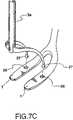
- FIG. 7Cshows an embodiment of the invention wherein a separate shaft is provided having distal portions adapted to fit within ports on a contact member.
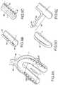
- FIGS. 7D and 7Eshow an embodiment of the invention wherein the contact members are formed from the distal portion of a shaft means for minimally invasive applications.
- FIG. 7Eshows an interconnecting member for joining the distal portions of the shaft means.
- FIG. 8shows an embodiment of the invention having a substantially annular contact member which is affixed to a shaft which is rotatable about the annular contact member and which may be locked into position at a given point about the periphery of the contact member.
- FIGS. 9A through 9Gshow embodiments of the invention where a positive or negative pressure is provided proximate to the contact members.
- FIG. 9Hshows an embodiment of the invention where a light source is provided to illuminate the area where the beating heart is contacted by the contact members.
- FIGS. 10A through 10Cshow embodiments of the invention where a surgical drape is operably associated with the contact members to provide an isolated visual field.
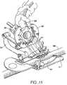
- FIG. 11shows the contact members of the invention associated with an apparatus to facilitate completing the anastomosis.
- FIG. 12shows an embodiment of the invention where the shaft means has associated therewith a separate vessel holder.
- FIGS. 13A through 13Eshow a cannula assembly preferred for providing minimally invasive access for the stabilizing means of the invention.
- FIG. 13Ahas screws for attaching the cannula assembly to the chest wall.
- FIG. 13Bhas a threaded portion about the periphery of the cannula.
- FIGS. 13C through 13Eshow a locking mechanism designed to engage adjacent ribs.
- FIG. 14shows a conical cannula having a smaller distal end to engage the surface of the beating heart and a larger proximal opening for introducing surgical instruments to the beating heart.
- FIGS. 15A and 15Bshow an embodiment of the invention inserted through the chest wall in a minimally invasive fashion via a cannula to bring the contact members into engagement with the beating heart.
- FIGS. 16A through 16Eshow an embodiment of the invention designed for minimally invasive insertion and removal of flexible contact members whereby the contact members are maintained in a retracted state within a hollow portion of a shaft and are deployed upon extension of a central shaft.
- FIGS. 17A through 17Dshow an additional embodiment providing minimally invasive insertion and removal of the contact members of the invention whereby individual contact members are rotated into position by a hinge at the distal end of a shaft.
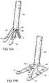
- FIGS. 18A through 18Dshow contact members which are attached to a guide that is positioned about a shaft such that downward movement of the guide causes the contact members to be deployed.
- FIGS. 19A and 19Bshow contact members of the invention attached to a shaft means by a plurality of struts that extend the contact members into position.
- FIGS. 20A through 20Eshow contact members of the invention that are rotatable about the distal portion of a shaft means by a plurality of hinges.
- FIGS. 21A through 21Cshow an embodiment having contact members formed from a unitary wire which is looped such that when extended from a body of the device, the contact members are deployed, and may be removed in a minimally invasive fashion by withdrawing a portion of the wire into the body of the device.
- FIGS. 22A through 22Cshow an embodiment of the invention wherein the contact members are formed from a helical coil which may be withdrawn into the hollow portion of a shaft for minimally invasive insertion and removal.
- FIGS. 23A and 23Bshow inflatable contact members that may be deflated for insertion or removal by being drawn into the body of a shaft.
- FIGS. 24A and 24Bshow a contact member of the invention formed from an inflatable annular cuff.
- FIGS. 25A and 25Bshow contact members formed from the divided portion of the distal end of a shaft.
- FIGS. 26A through 26Cshow contact members having sutures associated therewith for manipulation of a target artery.
- FIGS. 27A and 27Bshow an intravessel stabilizer adapted to fit within the target coronary artery.
- FIGS. 28A and 28Bshow contact members of the invention having means associated therewith for positioning epicardial tissue.
- FIGS. 29A and 29Bshow contact members of the invention having rotatable cylindrical rollers for collecting or spreading epicardial tissue proximate to a target artery.
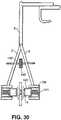
- FIG. 30shows a means for stabilizing the beating heart having a pair of contact members which are additionally comprised of a spring-tensioned frame having an extension that engages and spreads the tissue at the site of the surgery to better expose the coronary artery.
- FIGS. 31A and 31Bshow embodiments of the stabilizing means having a single shaft means associated with each contact member and where the shaft means are interconnected and can be moved independently about a pivot such that the contact members spread the surface tissue of the heart proximate to the target coronary artery to increase exposure of the target artery at the site of the anastomosis.
- FIGS. 32A through 32Cshow embodiments of the invention wherein the contact members have additional structures associated therewith for retraction of epicardial tissue
- the epicardial retractorsmay be comprised of pins which extend from the bottom surface of the contact member.
- FIGS. 33A and 33Bshow means for stabilizing the beating heart comprising a system which incorporates the retractor which spreads the ribs to provide surgical access to the heart.
- the stabilizing meansis comprised of a pair of stabilizing plates which may be used together with a lever device to improve exposure of the target coronary artery.
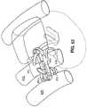
- FIGS. 34A through 34Dshow an embodiment of the invention having a lockable mechanism for depressing epicardial tissue on either side of a target coronary artery.
- FIG. 35shows a substantially planar stabilizing platform which contacts the heart at a site proximate to and surrounding the coronary vessel.
- the platformmay also have associated therewith at least one occluder which restricts or eliminates blood flow through an artery and an associated device for spreading the tissue proximate to the anastomosis.
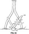
- FIG. 36shows an artery occluder comprised of a shaft portion and having a blunt portion to engage a target artery.
- FIGS. 37A through 37Cshow contact members having structures associated therewith for occluding the target coronary artery.
- FIGS. 38A and 38Bshow contact members of the invention having a flange associated therewith for use with sutures that surround the target vessel and may be used in connection with a movable shaft or suture guide to occlude the target vessel.
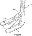
- FIG. 39shows an embodiment of the contact member of the invention having one or more fixtures attached, preferably to a planar surface thereof, and adapted to receive a surgical tool or accessory such as scissors, forceps, or surgical needles for the convenience of the surgeon during the anastomosis procedure.
- a surgical tool or accessorysuch as scissors, forceps, or surgical needles
- FIG. 40shows an embodiment of the invention having flex joints between the contact members, the interconnecting shaft, or the shaft means to provide continuous positioning of the contact members.
- FIG. 41shows an embodiment of the invention having lockable joints associated with the shaft means.
- FIG. 42shows a flexible, lockable arm which allows positioning in every direction to place and orient the contact members until the requisite degree of stabilization is achieved at which point the arm having a stabilizing means is fixed in position.
- the flexible, lockable armmay be attached to a retractor and is caused to become rigid when the entire stabilizing means is properly positioned.
- FIG. 43shows a conformable, lockable arm having hollow cylinders and spheres and an inflatable balloon member disposed therein to lock the arm into position.
- FIGS. 44A and 44Bshow embodiments of the invention having curved interlocking segments wherein teeth formed at the interconnecting surfaces of each segment prevent rotation of the respective segments.
- FIGS. 45A and 45Bshow a flexible shaft having means incorporated therein for fixing the position of the shaft.
- FIGS. 46A through 46Cshow an embodiment of the invention where a series of adjustable links have an a elastomeric hydraulic medium disposed therein and where application of force causes the elastomeric hydraulic medium to become rigid and fixes the position of the adjustable links.
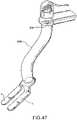
- FIG. 47shows an embodiment of the invention having a flexible shaft with a plurality of strands located therein wherein locking the strands in position at a distal portion causes the shaft to become rigid.
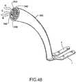
- FIG. 48shows a flexible shaft having a plurality of lumens disposed therein such that sealing of the lumens fixes the position of the flexible shaft.
- FIG. 49shows a fine adjusting mechanism wherein a plurality of threaded cables are attached to a proximal portion of a shaft means whereby turning the threaded cables causes the proximal portion of the shaft means to be adjusted.
- FIGS. 50A and 50Bshow embodiments of the shaft means having spring-loaded or air-damping mechanisms to restrict the vertical motion of the shaft relative to a stable support.
- FIGS. 51A and 51Bshow shaft means of the invention provided with fine adjustment mechanisms for vertical positioning of the shaft.
- FIG. 52shows a malleable shaft that is mounted on a fixture attached to a retractor blade and having a handle for vertical positioning of the shaft.
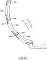
- FIG. 53shows a shaft means comprised of an adjustable arm formed from several interlocking segments attached to a cable.
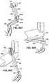
- FIGS. 54A through 54Cshow an adjustable shaft means of the invention wherein the position of the contact members are adjusted by a positioning handle located at the proximal portion of the shaft means and connected to a ball joint at the distal portion by a plurality of positioning wires.
- FIG. 55Ashows an embodiment of the stabilizing means of the invention having stabilizer bars suspended from the bottom side of a rib retractor wherein the stabilizer bars engage a ratchet means.
- FIG. 55Bhas malleable shafts attached to a retractor and to the contact members.
- FIGS. 56A through 56Dshow a shaft means of the invention having mechanisms for adjustable positioning of the shaft relative to a stable support.
- FIG. 57shows an adjustable arm for attaching a shaft means of the invention to a stable support wherein the shaft means passes through a ball joint that is adjustable by a fixture on the arm and wherein the arm is locked in place on the stable support by a latch mechanism.
- FIGS. 58A through 58Cshow embodiments of the shaft means of the invention for adjustable positioning of the shaft means relative to a retractor blade.
- FIGS. 59A through 59Cshow adjustable shaft means of the invention that extend from a retractor blade or a retractor arm and are continuously positioned relative to the retractor blade or retractor arm.
- FIG. 60shows an embodiment having a central shaft with a handle at the proximal end that is positioned by a plurality of shaft guides which are preferably attached to an interconnecting arm affixed to a retractor.
- FIG. 61shows an embodiment of the stabilizing meads of the invention having a pair of plates operably associated with a rib retractor and a sphere disposed between the plates to facilitate orientation of the shaft means.
- FIG. 62shows an embodiment of the invention having a shaft means comprised of an arm which extends from the interconnecting bar of a retractor to a position below the retractor blades and has a substantially horizontal shaft.
- FIG. 63shows means for stabilizing the beating heart of the invention operably associated with a rib locking mechanism.
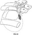
- FIG. 64shows stabilizing means of the invention adapted to be used as a means for positioning the beating heart, wherein the means are operably associated with a rib locking mechanism.
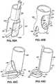
- FIGS. 65A through 65Dshow embodiments of the invention where the shaft means is comprised of a unitary hollow shaft.
- FIG. 66shows a means for stabilizing the beating heart having a sheath member with several pliable support attachments associated therewith which may include or be comprised of inflatable members which are positioned at one or several locations surrounding the heart and may have a lumen disposed within the sheath member for the introduction of air or a biocompatible fluid.
- FIG. 67shows a stabilizing means formed from a movable sheath member that is attached at either end to cranks mounted on the arms of a retractor.
- FIGS. 68A through 68Cshow a device for advantageous positioning of the heart comprised of a flexible sheet, preferably having a hydrogel coating on one side.
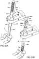
- FIG. 69shows an embodiment of the invention comprised of a plurality of telescoping shafts having the contact member affixed at their distal end and wherein the position of the telescoping shaft is manipulated and fixed by a hydraulic actuator.
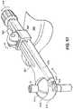
- FIG. 70A through 70Dshow an embodiment of the invention having a conformable arm comprised of a plurality of friction joints that are engaged when the motion of the beating heart presses against the contact member.
- FIGS. 71A through 71Dshow an embodiment of the invention having a contractible shaft attached to a flexible slide.
- the flexible slideis designed to be inserted into a seed-shaped clip which may be attached to a retractor blade.
- the contractible shaftis extended to engage the beating heart by application of hydraulic pressure, for example, by a syringe that is preferably supplied with a one-way releasable valve.
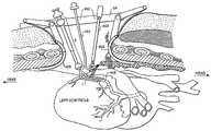
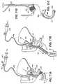
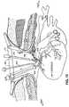
- FIG. 72is a view of the interior of the chest cavity during a CABG procedure on the beating heart with the stabilizing means operably associated with a retractor and being used in conjunction with other surgical apparatus to facilitate completing the anastomosis.
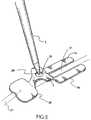
- FIGS. 73 and 74show the stabilizing means of the invention having been introduced through a thoracotmy to contact the beating heart to engage the heart tissue on either side of a target coronary artery to which an anastomosis is sewn.
- FIG. 75shows an embodiment of the invention having a pair of shaft means operably associated with ball joints that are affixed to opposing arms of a retractor.
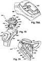
- FIG. 76shows a further embodiment of the invention including means for stabilizing the beating heart and a quick-locking base/shaft lock mechanism for solid attachment of the stabilizing means to a stable platform.
- FIG. 77shows an exploded perspective view of the stabilizing means of FIG. 76 , including a shaft-locking support mechanism for maneuverably supporting a shaft means of the stabilizing means.
- FIGS. 78 and 79show perspective views of the top and bottom, respectively, of a base of FIGS. 76 , 77 .
- FIG. 78Ashows a perspective view of one side of a pedestal means formed on a retractor arm.
- FIG. 80is a side view of the base of FIGS. 76-79 locked to a retractor arm.
- FIG. 81is a cross-sectional view of the base and retractor arm taken along section line 81 - 81 of FIG. 80 .
- FIGS. 82 and 83show side and top cross-sectional views respectively, of the shaft-locking support mechanism of FIG. 77 .
- FIGS. 82A and 82Bshow a cross-sectional view taken along section line 82 A- 82 A of FIG. 82 , and a bottom view of the shaft-locking support mechanism, respectively.
- FIGS. 84 and 85show side and top cross-sectional views of the shaft-locking mechanism employing an alternative shaft lock configuration.
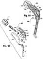
- FIG. 86is a perspective view of the alternative shaft lock of FIGS. 84 , 85 .
- FIGS. 87 and 88show exploded perspective and cross-sectional views respectively of a handle mechanism of the stabilizing means.
- FIG. 89is an exploded perspective view of a contact member of the stabilizing means.
- FIG. 90is a rear view of the contact member of FIGS. 76 , 77 and 89 .
- FIG. 91is a cross-sectional view of the contact member of FIG. 90 taken along section line 91 - 91 .
- This inventionis surgical instruments for stabilizing the beating heart and methods for their use.
- the means for stabilizing the beating heartare comprised of several alternative structures at least one component of which engages the surface of the heart to stabilize the beating heart during coronary surgery.
- the instrumentsprovide the capability to exert and maintain a stabilizing force on the heart by contacting the heart with a component of the stabilizing means and by functionally fixing the position of the stabilizing means throughout the duration of a surgical procedure.
- the instruments and methods of the inventionare preferably used for stabilization of the beating heart during a minimally invasive coronary artery bypass graft (CABG) operation which has been specially developed to facilitate completion of an anastomosis, to a target coronary artery for example by the placement of a bypass graft or the connection of a source artery, without requiring cardiac arrest such as cardioplegia or fibrillation and without cardiopulmonary bypass (CPB).
- CABGcoronary artery bypass graft
- CPBcardiopulmonary bypass
- the means for stabilizing the beating heartcan be applied in different surgical contexts, the devices described herein are most advantageously employed in a CABG procedure wherein only one or two minimally invasive incisions are placed in the chest.
- the complete structure of the stabilizing means of the inventionmay be provided by any of several structural embodiments which stabilize the beating heart while the minimally invasive surgical procedure is performed.
- Discrete components of the stabilizing meansmay also advantageously function in a multiple component system containing a retractor, an occluder, a surgical blower or suction device, an apparatus for holding the source artery, such as a LIMA holder, or other like discrete or integrated surgical devices or instruments that enable a surgeon to more efficiently complete the anastomosis.
- While the devices disclosed hereineach use mechanical means to stabilize the beating heart, certain embodiments are designed to operate on the entire heart while others have a more localized effect and may be applied to the area immediately proximate to a structure such as the target artery of the anastomosis. In each instance, the beating heart is effectively stabilized at the area where a surgical procedure is to be performed.
- Surgical access to the beating heartmay be achieved by several conventional surgical procedures which have been developed for traditional cardiac bypass surgery and the surgeon may thereby obtain the advantages provided by this invention in any procedure where the bypass is achieved on the beating heart without regard to the surgical method or access to the heart.
- the surgeontakes additional measures to restrict the movement of the entire heart within the chest cavity and may utilize certain embodiments disclosed herein to position or orient the beating heart.
- an adjustable strapwhich may have inflatable cushions attached to the straps, or having laces may be inserted beneath or surrounding the heart.
- the pericardiumwhen the pericardium is available, the pericardium may be incised and used to position the beating heart. When available, the surgeon can use the pericardium to raise and rotate the beating heart within the chest cavity and maintain the position by suturing the pericardium to the periphery of the incision.
- minimally invasive access to the beating heartis achieved by a thoracotomy, which is usually created in the left side of the chest by a smaller incision between the ribs, followed by insertion of a retractor between the ribs, spreading of the ribs, and securing the retractor in an open position to provide access to the source vessel and the target coronary artery.
- the use of the pericardium to position the beating heart as described aboveis particularly advantageous when the less invasive thoracotomy is used to provide access to the heart.
- an incisionis created in the pericardium, which is then sutured to the periphery of the thoracotomy.
- the pericardiumacts as a restraining sack to keep the beating heart in a desired orientation to achieve the anastomosis.
- the means for stabilizing the beating heartis introduced through the opening created by the thoracotomy and at least one component of the stabilizing device of the invention is brought into contact with the beating heart.
- the surgeonthen applies a stabilizing force to the beating heart via the stabilizing means which may then be fixed in place by attachment to a fixed support.
- the retractor platformmay also provide the stable support structure to which the stabilizing means is affixed.
- a common minimally invasive bypass procedure on the beating heartincludes an anastomosis which forms a connection between the left internal mammary artery (LIMA) as the source artery, and the left anterior descending artery (LAD) as the target artery.
- LIMAleft internal mammary artery
- LADleft anterior descending artery
- the LIMA to LAD anastomosisis used as an example herein but it is readily appreciated that the techniques and instruments described herein may be applied to other procedures depending on the clinical diagnosis and a patient's anatomy.
- the surgeonTo complete the anastomosis, the surgeon must dissect a portion of the LIMA by separating it from the internal chest cavity.
- the surgeonmay attach the dissected LIMA to the target coronary artery, i.e., the LAD.
- the stabilizing means of this inventionwould be used to stabilize the beating heart during at least the portion of the procedure during which the surgeon completes the anastomosis of the LIMA to the LAD.
- the structure of the portion of the stabilizing means which contacts the heartmay include one or more contact members which exert a stabilizing force on the heart proximate to the site of the anastomosis.
- a pair of contact membersmay be plates or rectangular members which are placed on either side of the target coronary artery at the site of the anastomosis and which may have friction means or tissue spreading or compressing apparatus associated therewith.
- the contact membersmay also be provided by a platform which may be substantially planar or which may be contoured to fit conformingly on the surface of the heart.
- the stabilizing meansmay also include a shaft means having several alternative embodiments to facilitate adjusting the position and orientation of the instrument.
- the shaft meansmay have an adjustable length and the axis of the shaft means may have at least one ball joint disposed within its length such that the orientation of the shaft means relative to another structure such as the contact members or stable support may be continuously varied.
- each of the individual embodiments described and illustrated hereinhas discrete components and features which may be readily separated from or combined with the features of any of the other several embodiments without departing from the scope or spirit of the invention.
- a means for stabilizing the beating heartis comprised of one or more, and preferably two, contact members 1 , which are attached to a rigid, or semi-rigid connecting shaft 2 which is in turn connected to shaft means 3 .
- the contact members 1may be substantially planar, may be slightly curved to conform to the shape of the heart, or may have a non-conforming curve to establish contact between only a portion of the contact member 1 and the beating heart.
- the contact members 1may have any of several alternate shapes including cylindrical members, members formed into a U-shape, or may comprise a pair of substantially parallel members spaced apart in a parallel configuration such that a target artery can be positioned between the contact members.
- the shape of the contact membersmay be varied depending on the clinical assessment by the surgeon, the design of the other features of the stabilizing means, or the design of other instruments used to complete the anastomosis.
- the contact members 1may have apertures, openings or attachments to facilitate connection with sutures or other devices to achieve the requisite stabilization, occlusion of the target vessel, or exposure of the target vessel.
- a pair of substantially planar rectangular contact members 1are attached at one end to a continuous connecting shaft 2 and are oriented in a substantially parallel fashion such that a target cardiac artery is positioned therebetween and passes along the greater length of the contact members 1 when the stabilizing means engages the heart, see FIGS. 72 through 74 .
- the connecting shaft 2may be a continuous shaft for interconnection of the contact members 1 without touching the artery or may include an additional member which may be operated to contact the target artery positioned between the contact members 1 , see FIGS. 36 through 38 , to occlude the passage of blood through the target artery.
- the contact members 1 , connecting shaft 2 , and shaft means 3may be composed of any non-toxic material such as a biocompatible plastic or stainless steel, having sufficient tensile strength to withstand a stabilizing force exerted on the heart via manipulation or fixation of the shaft means 3 to cause the contact members 1 to exert a stabilizing force on the beating heart.
- each of the individual contact member embodiments described and illustrated hereinhas discrete features which may be readily separated from or combined with the features of any of the other several embodiments such as differing designs of the shaft means, or other components of the invention by one of ordinary skill in the art.
- the shaft means 3may be a simple rigid post or may be comprised of a multi-component system designed to be adjustable in length and orientation at at least one point along its length.
- the length of the shaft means 3 and the orientation of the contact members 1 at the distal (lower) end of the shaft means 3can be altered by the surgeon.
- the length and orientation at the shaft means 3 relative to the contact members 1can be adjusted by controls located at the proximal (upper) end of shaft means 3 .
- distalrefers to a portion of a device most proximal to the heart while the term proximal refers to the opposite portion which may extend outside of the incision and which is most often readily manipulated by the surgeon).
- the shaft means 3has a housing 1 whose overall length is adjustable by a telescoping release operated by an annular thumbscrew 8 which tightens about housing 11 .
- the position and orientation of the contact members 1 relative to the shaft means 3is adjustable by virtue of a locking ball joint 5 which is interposed between the connecting shaft 2 and which is located at the distal end of shaft means 3 .
- the locking ball joint 5allows the position of the shaft means 3 to be positioned with three degrees of freedom relative to the contact members 1 .
- a locking ball joint 5is provided by including a block 6 within the shaft means 3 which conformingly contacts the ball joint 5 and fixes the position of the ball joint 5 .
- Block 6is compressed against ball joint 5 when a threaded push block 7 , connected to a long telescoping keyed shaft and socket combination 9 , is actuated by means such as a thumbscrew 8 at the upper end of the shaft means 3 .
- a rotation of the top thumbscrew 8loosens the lower ball joint 5 to allow continuous positioning of the shaft means 3 relative to the contact members 1 , and a counter-rotation locks the ball joint 5 into place, fixing the position of the contact members 1 relative to shaft means 3 .
- the upper end of shaft means 3may also have associated therewith an upper ball joint 13 such that the shaft means 3 can be oriented with four degrees of freedom relative to a fixed support such as a retractor (not shown).
- the position and orientation of the shaft means 3may thus be fixed relative to the stable support by a locking latch 14 or other conventional mechanism which prevents movement of the upper ball joint 13 .
- Either the shaft means 3 or the retractormay contain the locking latch 14 surrounding the upper ball joint 13 or any like fixture to firmly attach the shaft means 3 to a stable support, e.g., an anchor portion 15 extending from the retractor (not shown).
- the contact members 1preferably have friction means associated with their bottom surfaces 4 such that the contact members 1 more securely engage the beating heart when a stabilizing force is exerted on the shaft means 3 .
- the friction meansare preferably comprised of a textured surface covering the bottom surface 4 of the contact member 1 , and may be comprised of several biocompatible substances such as a textured rubber, textured or ridged aluminum, stainless steel or the like.
- the friction meansmay also be affixed to or comprised of a member disposed between the bottom surfaces 4 of the contact members 1 and the surface of the beating heart.
- the friction meansis provided to facilitate stabilization of the beating heart by maintaining close and conforming contact between the contact member 1 and the beating heart and reducing the amount of force necessary to be applied to the exterior of the beating heart in order to achieve stabilization.
- any number of different configurationsmay be employed to provide a textured surface, e.g., a diamond plate, granular, nail-bed, anti-skid, open foam, or other friction-providing configuration.
- the geometric configuration of the surface, having one side affixed to the contact member 1may be flat, triangular, rectangular, square, or circular.
- surfaces providing a functional adhesivemay be obtained using hydrogel, fibrogen, collagen, hydroxy apatite, or other biocompatible material and may be chemically etched, mechanically scored, or electrically activated.
- one practical method for providing the friction meansis a separate member affixed to the bottom surface 4 of a contact member 1 comprising a snap-in member 16 having means 17 for removably attaching the snap-in member 16 to the bottom surface 4 of the contact member 1 .
- This removable attachment featuremay be readily provided by a post 18 affixed to each snap-in member 16 and which fits engagingly in a port 19 formed in the body of the contact member I, or by other like configuration.
- This embodimentoffers several advantages in disposability and ease of manufacture, particularly where it is desirable to provide an adhesive or friction-providing member separately to the bottom surface 4 of the contact member 1 , and especially where the friction or adhesive member is formed of a different material than the body of the contact member 1 .
- the bottom surface 4 of the snap-in member 16may have any of the configurations described previously (See FIGS. 1B and 1D through 1 G).
- the contact members 1 of the inventionmay be provided with a friction-providing and/or cushioning material at the lower or bottom surface 4 of the contact member 1 to cushion the point where the contact member(s) 1 engage the beating heart.
- FIG. 3shows an exemplary material 20 comprising a textured soft rubber or fluid-filled member affixed to the bottom or lower surface 4 of the contact members 1 to prevent damage to the heart tissue, and to minimize slippage.
- a fundamental element of the inventionis the contact members which engage the surface of the beating heart, in some embodiments proximal to the site of the anastomosis, to directly apply the stabilizing force to the beating heart.
- the actual shape, size, configuration, and relative orientation of the contact membersmay vary without departing from the spirit of the invention.
- the contact members 1 that engage the surface of the beating heartmay be provided by a solid structure 21 , preferably a dense metal, which provides an added weight to add to the stabilizing effect achieved by contacting the beating heart with the stabilizing means of the invention.
- This embodimentfacilitates motion cancellation and stabilization of the beating heart by adding additional weight directly at the site where the contact member engages the beating heart, which in this embodiment is at the site of the anastomosis.
- two contact members 1 a , 1 bengage the beating heart at their lower or bottom surface 4 , have a greater thickness at their outer edges, and have an opening 22 positioned therebetween, and which traverses the entire space between the contact members 1 a , 1 b such that a vessel may be positioned therebetween.
- FIG. 4Cshows an integrated apparatus which may advantageously apply the contact members 1 to the surface of the beating heart by the action of a balance provided by an adjustable weight 24 and counterweight 25 mounted on opposite ends of a shaft 26 mounted on a fulcrum 27 which is preferably affixed to a stable support such as the operating table or an access platform providing retraction during the surgery.
- a balanceprovided by an adjustable weight 24 and counterweight 25 mounted on opposite ends of a shaft 26 mounted on a fulcrum 27 which is preferably affixed to a stable support such as the operating table or an access platform providing retraction during the surgery.
- This embodimentprovides a continuously variable quantity of stabilizing force directed downward by the positioning of the weights 24 , 25 and the rotation of the shaft 26 about the point of the fulcrum 27 .
- the surgeonmay rest the contact members 1 on the surface of the beating heart with a minimal force applied, and by moving the adjustable weight 24 away from the fulcrum, cause additional force to be applied, via the shaft means 3 , and the contact members 1 , to the surface of the beating heart.
- the positioning of the contact members 1 at the surface of the beating heart to provide the requisite degree of stabilizationmay be achieved by several techniques designed to apply a mechanical force to the contact members that rest in a conformingly fashion at the surface of the beating heart to substantially arrest the movement in an atraumatic manner.
- the device shown in FIG. 5has a pair of contact members 1 a , 1 b disposed in substantially parallel fashion as in the embodiments previously described. However, the device has an additional counter contact member 28 that also engages the surface of the beating heart, but does so at a point slightly removed from the point of engagement of the other contact members 1 a , 1 b which are preferably located at the site of the anastomosis.
- the shaft means 3may be attached to and be rotatable about a point 29 located between the contact members 1 a , 1 b and the counter contact member 28 and preferably at a point on the connecting shaft 2 that is slightly elevated.
- the shaft means 3is preferably rotatable, for example by virtue of a ball joint 30 , about the point 29 of contact thereby permitting the contact members 1 to self-align and engagingly conform to the surface of the beating heart.
- a stabilizing forcewhen a stabilizing force is applied to the surface of the beating heart, the force directed down the length of the shaft means 3 is not centered over the site of the anastomosis.
- the counter contact member 28may also be configured to occlude the target vessel 31 .
- an embodiment of the type of FIG. 5may be selected by the surgeon depending on the particular clinical indication, the particular physiology of a given patient; and/or the surgical environment dictated by the access method used to gain access to the beating heart, for example, stemotomy, thoracotomy, or puncture incision.
- FIGS. 6A and 6Bshow an embodiment of the invention having a plurality of particles or beads 32 disposed within a substantially flexible tubular structure or structures 33 , and which may have a vacuum lumen (not shown) located therein, to provide a contact means 1 whose shape and position is adjustable.
- the flexible tube structure 33has a malleable member 34 such as a wire disposed along the length thereof to provide a structural memory function and additional tensile strength.
- the flexible tube 33is a single unitary structure which can be bent, typically in a U-shape configuration, to engage the surface of the heart and may have a plurality of discs 35 disposed along the malleable member 34 .
- the stabilizing meansmay be provided by a plurality of contact members 1 a , 1 b as otherwise described herein.
- the plurality of the flexible contact members 1 a , 1 bmay be provided with a plurality of beads or particles 32 disposed therein and may additionally have the ability to be inflated selectively, or selectively deflated, to adjust or fix the position of the contact members 1 .
- the particles 32are compressed by atmospheric pressure causing the tubular structure 33 to become rigid, thereby fixing the information of the contact members 1 .
- adjustable placement of the contact membersmay be particularly useful in a minimally invasive procedure.
- Contact members that releasably contact or are releasably attached to a shaftmay be deployed by separate insertion of the contact member, and a shaft or shafts which may be independently introduced, manipulated, and withdrawn to provide a stabilizing device held in place by pressure exerted on the shafts while the anastomosis procedure is performed at which time the contact members and shafts are removed in an atraumatic manner.
- a unitary contact 1has a plurality of recessed ports 36 adapted to receive the distal end 37 of a shaft means 3 , wherein the distal end 37 is shaped to fit conformingly within the recessed port 36 and wherein the shaft means 3 may be removably attached to the contact member 1 .
- this embodimentprovides the advantage that the shaft means 3 may be introduced through a plurality of very small incisions such that several shaft means 3 may removably engage the contact member 1 at the several points about the periphery of the contact member 1 where the recessed ports 36 are formed in the contact member 1 and receive the distal end 37 of a plurality of shaft means 3 .
- FIG. 7Cillustrates a separate removable shaft means 3 a that may be utilized with any of the embodiments of the contact members 1 previously described.
- the separate shaft means 3 ais separately introduced and has a pair of distal ends 37 that engage equivalently oriented and spaced ports 36 found in the contact member 1 to provide an additional positioning and stabilizing capability by manipulating the separate shaft means 3 a when the distal ends 37 engage the ports 36 .
- FIG. 7Dis a simplified use of separate shaft means 3 a having an integral contact member 1 formed from the distal portion 38 of the separate shaft means 3 a .
- the separate shaft means 3 aare separately introduced into the surgical field through minimally invasive puncture incisions and are separately positioned to bring the distal portion 38 of each of the separate shaft means 3 a to contact the surface of the heart.
- the separate shafts 3 amay be joined at the most distal tip by a discrete interconnecting member 39 having openings 40 configured to receive the most distal tip 37 of both of the separate shaft means 3 a.
- FIG. 8is an additional embodiment of the contact members 1 of the invention generally comprised of an annular structure 41 which is rotatable relative to the shaft means 3 which is attached at a point about the periphery of the contact member 1 .
- a portion of the bottom surface 4 of the annular portion 41contacts the beating heart at a site proximate to the target site for the anastomosis.
- the annular portion 41 of the contact member 1may be provided with a lockable fixture 42 which engages the distal end of the shaft 43 , where the shaft means 3 contacts the annular structure 41 , to lock the shaft in place.
- the shaft means 3may rotate freely about the periphery of the annular portion 41 of the contact member 1 .
- annular contact member 41has a passage 44 formed through the bottom surface 4 of the annular contact member 41 where the target vessel 45 passes beneath the annular contact member 41 .
- the annular contact member 41may have substantially planar surfaces 46 which are generally co-planar with the bottom surface 4 of the annular contact member 41 and have a rectangular opening therein for access to the target vessel 45 . Planar surfaces 46 may assist in providing stabilization at the tissue proximate to the anastomosis, and which also assist in positioning the target vessel 45 relative to the annular contact member 41 .
- the contact members of the inventionmay also be provided with other related apparatus or fixtures that are commonly used in traditional surgical procedures. Such structures or fixtures may be operably associated with the body of the shaft means 3 , the interconnecting shaft 2 , or the contact members 1 .
- a suction (negative) pressure or a blower (positive) pressureis useful to maintain a clear and dry anastomosis site.
- the positive or negative pressuremay be provided to the contact member by a plurality of ports 47 formed in the body of the contact member. Each port is in pneumatic communication with a lumen 48 that is in turn connected to a suction or positive pressure source.
- the suction or positive pressureis applied to the site of the anastomosis via ports 47 .
- the ports 47are disposed in the top surface of the contact members 1 and have aligned openings in the direction of the anastomosis site.
- the plurality of ports 47may be provided in a discrete lumen 48 which is affixed to, and runs longitudinally along, the length of the contact member 1 .
- the plurality of ports 47are preferably disposed in a linear configuration along one surface of lumen 48 to provide negative suction pressure or a positive flow of pressure about the surface of the contact member 1 .
- the plurality of ports 47 and the lumen 48may be provided in a manifold-like fashion wherein the openings of the plurality of ports 47 are formed in the body of the contact member 1 , as is the lumen 48 which is in communication with each port 47 .
- a single slotmay be formed from the lumen 48 , such that the slot runs along the greater length of the contact member 1 as shown in FIG. 9D .
- the lumen 48may be provided as a malleable tube which is separable from the contact member 1 along at least a malleable portion 49 of said lumen 48 .
- port(s) 47may be selectively positioned at any point proximate to the contact member 1 .
- a manifold similar to that shown in FIG. 9Cmay be provided within the body of the contact member 1 in a configuration wherein the ports 41 are more closely associated with the interconnecting shaft 2 or the shaft means 3 .
- the ports 47are in communication with a lumen 48 that runs the length of the shaft means 3 terminating in the plurality of ports 47 .
- the plurality of ports 41may apply the positive or negative pressure from the portion of the interconnecting shaft 2 that joins the individual contact members 1 .
- a lumen 48 having a malleable portion 49may be provided for selective positioning of a positive or negative pressure which may be applied at any point proximate to the stabilizing means of the invention by manipulating the position of the malleable portion 49 of the lumen 48 to selectively position port 47 .
- FIG. 9Hsupplies an incandescent or fiber optic light source 48 a proximate to the contact members 1 by placing the light source within the shaft means 3 to have an opening or lens to provide light at the site of the stabilization.
- FIG. 10Ashows a retractable and extendable drape 50 surrounding shaft means 3 .
- the retractable drapeis closely conformed to the shaft means 3 to be unobtrusive.
- the drape 50may be affixed to the shaft means 3 by a washer element 52 that is directed downward to deploy the drape 50 .
- FIG. 10BAn additional embodiment, shown in FIG. 10B , has a surgical drape 50 affixed to the outer portion of each contact member 1 a , 1 b . While this configuration is not retractable, surgical drapes 50 as shown in FIG. 10B may be provided with structural support members 53 that provide tensile strength and shape to the surgical drape 50 and which may provide supplemental stabilizing force by contacting the beating heart about the periphery of the contact members 1 a , 1 b . An additional configuration for surgical drapes 50 affixed to contact members 1 is shown in FIG.
- a plurality of drape supportsprotrude radially from several points about the periphery of the contact members 1 a , 1 b and terminate in drape fastening means 54 a at their most distal portion.
- a portion of the drape 50is attached to each drape fastening means 54 a to spread the drape over the surgical site and may provide coverage extending in all directions outward from the contact members 1 .
- a mechanical fixture to facilitate completing the anastomosismay be directly attached to the contact member 1 .
- a separate device to facilitate completing the anastomosisis generally comprised of a hinged or rotatable vessel support member 55 that permits selective positioning of the source vessel 59 , such as the distal end of an internal mammary artery or the distal end of a venous or arterial graft, proximate to the target vessel 56 .
- the vessel support member 55is oriented on the contact member 1 such that the vessel source brought into direct alignment with an arteriotomy formed in the target vessel 56 , which is disposed between the contact members 1 .
- a vessel receiving member 57is closely associated with the contact members 1 and generally surrounds the arteriotomy in the target vessel 56 .
- the vessel support member 55has an anastomosis coupling fixture 58 that is attached to the distal end of the source vessel and is shaped to be brought into engagement with the vessel receiving member 57 .
- the anastomosis coupling fixture 58is attached to the periphery of the IMA or graft such that when the vessel support member 55 is positioned proximate to the arteriotomy, the vessel receiving member 57 and the anastomosis coupling fixture 58 are brought into alignment such that a fluid communication between the source vessel 59 and the target vessel 56 is established upon completion of the anastomosis. Completion of the anastomosis is facilitated by an automatic suturing securing mechanism 60 or other like apparatus for tightening the sutures to join the two vessels.
- the vessel receiving member 57 and the anastomosis coupling fixture 58are operably associated with a plurality of sutures 61 which penetrate the periphery of the arteriotomy formed in target vessel 56 and connect the periphery of target vessel 56 to the periphery of the source vessel 59 .
- the automatic suturing device 60brings the vessels into close conformity and completes the anastomosis procedure to establish fluid communication between the source vessel 59 and the target vessel 56 .
- a separate member for conveniently holding the source vesselmay be provided without a dedicated apparatus for completing the anastomosis.
- a malleable wire 62is operably affixed to the shaft means 3 or to the contact member (not shown) and has a source vessel holder 63 such that the source vessel 64 may be prepared and conveniently held at a point away from the target vessel 56 until the surgeon is prepared to complete the anastomosis.
- the source vessel holder means 63is comprised of a clamp for gripping and maintaining the source vessel 64 in a preferred configuration prior to completing the anastomosis, such as by separating or spreading the tissue attached to the most distal portion of the source vessel 64 to maintain the integrity and patency of the distal end of the source vessel 64 .
- the instruments of the inventionbe used in a minimally invasive bypass graft procedure wherein a minimal thoracotomy provides access to the beating heart.
- a minimal thoracotomyis a small surgical opening provided between the ribs and is formed, to the extent possible, proximate to the target artery of the beating heart where the anastomosis is to be formed.
- a cannulamay be disposed between the ribs to provide access to the beating heart. Referring to FIGS. 13A through 13E , alternate configurations for a cannula disposed between adjacent ribs are shown. The embodiment of FIG.
- 13Ahas a cannula support bracket 67 having a plurality of holes through which screws 66 may pass to provide means to attach the assembly to the chest such as by placing the screws in adjacent ribs 69 a , 69 b .
- the cannula receiving assembly 67may have one slot 65 formed therein such that one of the screws 66 may slide therein for spreading the adjacent ribs 69 a , 69 b apart.
- the cannula receiving assembly 67provides an opening between adjacent rib's 69 a and 69 b such that the cannula 68 may be passed therethrough. Referring to FIG.
- the cannula receiving assembly 67is replaced by a cannula 68 surrounded by a large thread means 70 .
- the distal end 71 of the cannula 68may be inserted between the ribs and rotated such that the thread means 70 cause cannula 68 to be advanced between the adjoining ribs 69 a , 69 b , and by virtue of the expanding diameter of the thread means 70 , to spread adjoining ribs 69 a , 69 b apart while positioning the cannula 68 therebetween.
- a cannula assembly 75is provided having a claw mechanism comprised of opposing blades 73 and interlocking member 72 .
- Adjacent ribs 69 a , 69 bare engaged by opposing blades 73 , and, by forcing the cannula 68 downward, the opposing blades 73 rotate outwards until a locking member 72 fixes the position of the opposing blades 73 in a locked and opposing relationship as shown in FIG. 13D and 13E .
- a locking member 72fixes the position of the opposing blades 73 in a locked and opposing relationship as shown in FIG. 13D and 13E .
- adjacent ribs 69 a and 69 bare spread apart by opposing blades 73 and the cannula assembly 75 is fixed in position by locking member 72 such that cannula 68 is positioned to provide access to the beating heart.
- a modified large diameter cannula having an extended vertical heightmay perform several functions in a minimally invasive CABG procedure.
- an enlarged cannula 74may be provided in the shape of an inverted cone structure having an enlarged proximal opening 76 with an enlarged diameter, and a distal opening (not shown) in distal portion 75 having a reduced diameter and where said distal opening 75 abuts the surface of said beating heart.
- the inverted conical shape of the cannula 74forcibly spreads adjacent ribs 69 a , 69 b , and provides a stabilizing force when the distal portion 75 contacts the surface of the beating heart.
- Surgical access to the stabilized heartis provided through enlarged proximal opening 76 .
- FIGS. 15A and 15Bshow an embodiment of the invention in use with a conventional cannula.
- a conventional cannula 77is inserted through a puncture incision in chest wall 80 .
- the distal end of the stabilizing means 78(similar to FIGS. 31A and 31B below), is introduced in a contracted configuration through the cannula 77 to bring the distal end thereof in contact with the surface of the beating heart 79 .
- the stabilizing means of the inventionare fully inserted through the cannula 77 and manipulated to bring the contact members 1 into contact with the surface of the beating heart 79 .
- the contact members 1are spread apart at the surface of the beating heart to provide the stabilizing function during the surgical procedure.
- the means for stabilizing the beating heart of the inventionare preferably provided in an embodiment where the contact members 1 that engage the surface of the beating heart are inserted and withdrawn from the surgical field in a position or a configuration having a reduced dimensional profile, i.e., a reduced effective diameter when inserted and removed from the thoracic cavity.
- these embodimentsare particularly useful when the surgery is performed through a plurality of puncture incisions.
- each contact member 1 a , 1 bis rolled into a collapsed, annular configuration to reduce the effective diameter of the device by having the contact members 1 a , 1 b maintained within the shaft 82 when the device is inserted through an incision.
- each contact member 1 a , 1 bis attached to a central shaft 83 by a connecting shaft 2 which has a tensioning wire 84 or spring mounted to the connecting shaft 2 and the central shaft 83 to deploy each contact member 1 a , 1 b when the central shaft 83 is extended from the substantially cylindrical main shaft 82 in which the contact members 1 a , 1 b are originally retained.
- the contact members 1 a , 1 bare maintained in the retracted annular configuration of FIG. 16A until deployed within the surgical field as shown in FIGS. 16B through 16E by extending the central shaft 83 downward causing the contact members 1 a , 1 b to be deployed below the main shaft 82 .
- the contact members 1 a , 1 bunfold from their annular configuration and deploy into their substantially planar shape as shown in FIG. 16C .
- the contact members 1 a , 1 brotate into position relative to the central shaft 83 by the tension in wire or spring 84 which is preferably disposed to act upon the connecting shaft 2 to cause contact members 1 a , 1 b to be fixed in a substantially parallel position to one another and substantially co-planar with the surface of the beating heart as shown in FIGS. 16D and 16E .
- FIG. 16Ashows the contact members 1 a , 1 b in their collapsed or retracted position.
- FIG. 16Bshows the contact members in the process of being deployed as the central shaft 83 is extended from the bottom of the main shaft 82 .
- FIGS. 16D and 16Eshow the tensioning wire 84 for repositioning the contact members 1 a , 1 b in the desired position for use in surgery.
- FIG. 16Cshows the central shaft 83 fully extended from the bottom of the body of the main shaft 82 causing the deployment of the contact members 1 a , 1 b into the desired configuration for stabilizing the beating heart.
- the connecting shaft 2 joining the individual contact members 1 a , 1 bis hinged 85 , such that upon completion of the anastomosis, the contact members 1 a , 1 b may be withdrawn by pulling the central shaft 83 upward relative to the main shaft 82 and into the body of the device, thereby causing the contact members 1 a , 1 b to be removable in a low-profile configuration.
- FIGS. 17A through 17Da similar strategy as is shown in FIGS. 16A through 16E is used whereby a pair of contact members 1 a , 1 b are deployed by a main shaft 86 within a hollow portion of the body 87 of the device.
- a pair of non-flexible contact members 1 a , 1 bmay be provided to stabilize the beating heart in a minimally invasive environment by containing the contact members 1 a , 1 b in a body or housing 87 which is inserted through the minimally invasive incision.
- the contact members 1 a , 1 bare mounted to a central shaft 86 by virtue of a pin or hinge 88 which affixes the end of the contact members 1 a , 1 b to the central shaft 86 such that the contact members 1 a , 1 b may be deployed by rotating around the pin or hinge 88 when the shaft 86 is extended downward from the body 87 of the device.
- the opposite portion of the contact members 1 a , 1 b(most distal from the hinge) may fit within a guide fixture 89 concentrically associated with the central shaft 86 that retains the contact members 1 a , 1 b in the desired configuration prior to deployment.
- the central shaft 86telescopes from an opening in the distal end of the body or housing 87 of the device by a distance at least as great as the overall length of the contact members 1 a , 1 b , at which point the contact members 1 a , 1 b may be deployed and locked into position, for example, in an orientation substantially perpendicular to the shaft as shown in FIGS. 17A and 17C .
- the central shaft 86may be rotated using the guide fixture 89 which is positioned downward to engage the contact members 1 a , 1 b .
- the guide fixture 89engages the contact members 1 a , 1 b , the pin 88 , or the locking mechanism 90 , and by applying mechanical force, the position of the contact members 1 a , 1 b may be adjusted.
- the central shaft 86is withdrawn into the body 87 of the device.
- the housing 87may disengage the locking mechanism 90 from the guide fixture 89 releasing the position of the contact members 1 a , 1 b thereby allowing the contact members 1 a , 1 b to be returned to their original or other configuration that allows the contact members 1 a , 1 b to be drawn into the body of the device 87 to facilitate minimally invasive removal thereof.
- FIGS. 18A through 18Dshow an analogous embodiment having contact members 1 a , 1 b retained in the undeployed configuration suitable for insertion through a minimally invasive incision.
- the contact members 1 a , 1 bmay be maintained in a retracted position such that the length of the contact members 1 a , 1 b is substantially parallel to the central shaft 92 .
- the proximal end of each contact member 1 a , 1 bis affixed to the guide fixture 93 while the distal end (below the hinge at central portion 91 ) has the bottom surface 4 formed therein and is affixed to the distal end of the central shaft 92 . Referring to FIG.
- the contact members 1 a , 1 bare deployed by the downward motion of the guide fixture 93 , such that the contact members 1 a , 1 b fold about the central portion.
- the contact members 1 a , 1 bare formed of a pair of two-part structures wherein the lower structure contains the bottom surface 4 .
- FIGS. 19A and 19Bshow an additional embodiment having foldable contact members 1 a , 1 b wherein a central shaft 94 is affixed to a plurality of hinged struts 95 that are connected to opposite ends of contact members 1 a , 1 b about a hinged central portion 96 .
- the hinged struts 95deploy outward.
- the individual contact members 1 a , 1 bfold at the central hinged portion 96 to reduce the overall dimensional profile of the device for minimally invasive insertion or removal.
- the contact members 1 a , 1 bare extendable to a substantially planar configuration as with other embodiments disclosed herein.
- FIGS. 20A through 20Eshow the central shaft 97 and contact members 1 a , 1 b with alternate configurations for positioning the contact members for minimally invasive insertion and removal.
- first hinges 98are provided in the connecting shaft 2 such that the contact members 1 a , 1 b can be rotated approximately 90° out of their co-planar configuration.
- a second hinge 99is provided between the shaft means 3 and the connecting shaft 2 to tilt the distal end of the contact members 1 a , 1 b downwards as shown in FIG. 20C .
- the embodiments of FIGS. 20D and 20Eshow modified such that two interconnecting shafts 2 a , 2 b maintain the contact members 1 a , 1 b in slightly separate, yet parallel, vertical positions.
- a single hinge 100 with a vertical axis of rotationallows the contact members to be brought into close conformity before being tilted downward.
- FIGS. 21A through 21Cshow a deployable stabilizer of the invention having contact members comprised of a single continuous wire 101 that is deployable from within a housing or body 102 which is ideally inserted through a minimally invasive incision.
- the single continuous wire 101may be coiled and contained within the housing 102 such that the dimensional profile of the stabilizer is minimized for insertion.
- the wire 101 which forms the contact member(s) of this embodimentis preferably round and smooth, and may be formed of a material such as Nitinol that is collapsible, and deployable into a pre-determined shape. As can be seen in FIG.
- the wire 101is extended from the body 102 of the device to form at least one loop 103 wherein at least one side 104 of the loop 103 contacts the surface of the heart.
- at least two loops 103extend from the body
- 21A through 21Care drawn upward by exerting force on the wire 101 , and the contact members comprised of loops 103 are drawn into a configuration which is in alignment with the body 102 of the device such that their removal may be achieved through a puncture incision with minimal additional trauma to the patient.
- the contact membersmay be formed of a helical wire coil 105 as shown in FIGS. 22A through 22C .
- the contact members 1 a , 1 bare deployed by extending a tubular central shaft 106 through a body or housing 107 of the device to deploy the contact members 1 a , 1 b .
- the downward motion of the central shaft 106is terminated by the contact between a stop 109 and the distal end of the body 107 .
- the contact members 1 a , 1 bare withdrawn into the body 107 of the device upon completion of the surgical procedure by pulling the central shaft 106 vertically through the body 107 of the device.
- a predetermined curve in the helical coil 105may be provided by spacing members 108 placed between adjacent individual loops 105 a and 105 b of the helical coil 105 .
- the central locking wires or cablesmay be tensioned upon deployment to increase the rigidity of the structure.
- FIGS. 23A and 23BAn additional configuration for minimally invasive insertion and removal is shown in FIGS. 23A and 23B wherein the contact members 1 a , 1 b are formed of an inflatable balloon 110 that is pre-shaped to provide any desired configuration of the contact members 1 a , 1 b .
- FIG. 23Ashows a pre-formed inflatable balloon 110 in an inflated state and extended from the housing 111 . Inflation is achieved by a central shaft 112 disposed within the central lumen 111 .
- FIG. 23Bshows the inflatable balloon 111 in an un-inflated state for insertion or for removal.
- an inflatable contact membermay also be provided by a cuff 113 which is positioned such that the circumference of the cuff 113 contacts the beating heart and the ribs about its periphery.
- the target vessel 114is positioned to bisect an annular cuff 113 to provide maximum stabilization.
- separate contact members 1 a , 1 bas previously described herein, may be integrally formed with the cuff 113 by mounting the contact members 1 a , 1 b in the wall of the cuff 113 to extend into the interior thereof.
- FIGS. 25A and 25Billustrate an embodiment of the invention which provides minimal trauma to the patient during insertion and removal of the stabilizing means by containing a simple stabilizer in an instrument having a housing 115 with an extremely limited cross-section such that the instrument can be inserted through an extremely small incision.
- the entire stabilizing meansis contained within the hollow housing 115 and is comprised of a pair of contact members 1 a , 1 b which are joined at the most distal end thereof. As can be seen in FIG.
- the contact members 1 a , 1 bare formed from a unitary shaft 116 having a divided portion 117 at the distal end such that upon deployment from the housing 115 of the device, the divided portion 117 splits into two contact members 1 a , 1 b joined at their most distal tip 118 and which may be brought into contact with the beating heart along the divided portion 117 of the unitary shaft 116 .
- FIGS. 26A , 26 B, and 26 Cshow embodiments where means for fixing the position of epicardial tissue is comprised of sutures 119 used in combination with the contact members 1 a , 1 b to stabilize and position tissue surrounding the site of an anastomosis and the target cardiac artery.
- sutures 119used in combination with the contact members 1 a , 1 b to stabilize and position tissue surrounding the site of an anastomosis and the target cardiac artery.
- a series of sutures 119is placed through the epicardial tissue (not shown) and looped around the contact members 1 a , 1 b to effectively position several points on the surface of the beating heart in fixed relationship to the contact members 1 a , 1 b .
- the contact members 1 a , 1 b and optionally the shaft means 3 associated therewithhave passages 120 formed therein through which a suture line 119 may be passed.
- FIG. 26Aa series of sutures 119 is placed through the epicardial tissue (not shown) and looped around the contact members 1 a , 1 b to effectively position several points on the surface of the beating heart in fixed relationship to the contact members 1 a , 1 b .
- the contact members 1 a , 1 b and optionally the shaft means 3 associated therewithhave passages 120 formed therein through which a suture line 119 may be passed.
- a single suture 119is passed through the body of the shaft 3 , exits from within the first contact member 1 a through a passage 120 formed therein, passes underneath the target vessel 121 , emerges from an opposite side of the target vessel 121 , and enters a passage 120 in the opposite contact member 1 b joined to the first contact member 1 a by the connecting shaft 2 .
- the suture 119exits the opposite contact member 1 b again passes beneath the target vessel 121 , reenters the first contact member 1 a at a separate passage 120 , and passes through the body of the first contact member 1 a and into the shaft means 3 .
- the suture linesmay be manipulated by the surgeon from a remote location, such as external to the incision in the chest, to remotely position the vessel by drawing tension on the suture line 119 .
- FIG. 26Cshows a similar arrangement for the suture line 119 as in FIG. 26B , however in FIG. 26C , apertures 122 in the body of the contact member 1 are used to select the direction of the suture 119 rather than having passages 120 which traverse the body of the contact member 1 .
- a separate sliding shaft 123may be provided that gathers and is traversed by the sutures 119 .
- the step of drawing tension on the suture line 119is facilitated by advancing the sliding shaft 123 to abut the contact member 1 and exerting a small downward force on the sliding shaft 123 while exerting an upward force to draw tension on the suture line(s) 119 .
- the target vessel 121is raised while the potential for displacing the contact member 1 is minimized because the upward force exerted on the suture lines 119 is countered by the downward force exerted on the sliding shaft 123 .
- a modification of the contact member 1 of the inventionmay be provided by a structure formed at the distal end of the shaft means 3 and which is inserted directly into the arteriotomy 124 formed in the target vessel 125 .
- This intravessel stabilizer 126has a body designed to fit conformingly about the interior of the target vessel 125 , and may be in communication (including fluid communication) with a hollow portion of the shaft means 3 .
- the body 126 of the intravessel stabilizing meansmay be a substantially cylindrical lumen as shown in FIG. 27B and should have an overall length which is greater than the length of the incision creating the arteriotomy 124 . Additionally, in the embodiment of FIG.
- the intravessel stabilizer 126may be perpendicular to the shaft means 3 and have cuffs 127 at the distal end of the body 126 to provide conforming engagement with the interior of the target vessel.
- this embodiment of the stabilizing means of the inventionis preferably used in connection with a plurality of sutures 128 that penetrate the edges of the target vessel about the circumference of the arteriotomy 124 .
- FIG. 28Ashows a functional clamp 128 formed by a crimping contact member 1 that has a fold 129 disposed longitudinally at the center of the length of the contact member 1 .
- the crimping action of the contact member 1grasps the epicardial tissue 130 at the heart surface 131 and contains it within the folded contact member 132 .
- a plurality of open passages 133are provided in a contact member 1 that has a slidable member 134 disposed within a slot 135 formed within the contact member 1 .
- the slidable member 134When sufficient force is exerted in a downward direction on shaft 3 to force epicardial tissue 130 through the open passages 133 , the slidable member 134 then may be actuated to grip the tissue 130 contained within the open passages 133 .
- the tissuemay be spread to more readily expose the target vessel 136 of the anastomosis.
- a similar functionis provided by a pair of contact members 1 , that are formed of circular rollers 137 that lie longitudinally parallel to the direction of the target vessel 136 as shown in FIGS. 29A and 29B .
- the contact members 1may be comprised of movable rollers 137 , belts, or pivoting surfaces that may be rotated independently about an axis 138 dedicated to each contact member 1 such that the epicardial tissue 130 is gathered or spread, depending on the respective directions of rotation of the rollers 137 , as desired at the surface of the heart to expose the target vessel 136 .
- each of these embodimentsmay be provided with contact members 1 that are independently movable in a parallel, V-shaped, or other adjustable configuration as described and illustrated herein.
- the contact members 1may be further comprised of a spring-tensioned frame 139 having a movable frame extension 140 which may have pins or an associated friction means at the bottom surface 4 of the contact members 1 a , 1 b to engage the tissue proximate to the target artery.
- the movement of the frame extension 140is tensioned by a spring means 141 which draws the frame extension 140 toward the contact member 1 after the frame extension 140 has been manually positioned to engage the tissue.
- the use of this embodiment of the inventionis the same as is described for the other embodiments herein, with the frame extension 140 providing the improved exposure of the target artery by retraction of the epicardial tissue.
- the contact members 1may be attached at one end by a connecting shaft 2 which is attached to a shaft means 3 as described above.
- the connecting shafts 2may also be positioned relative to one another by a conventional threaded post 142 with a positioning thumbscrew 143 .
- the stabilizer meansmay also be comprised of a single shaft means 3 connected to each contact member 1 .
- the shaft means 3are interconnected at an intermediate pivot point 144 which permits the contact members 1 to be continuously positioned in parallel fashion relative to one another.
- the proximal (upper) portion at the individual shaft means 3may have grips adapted to be grasped by the hand or may have an anchor portion 145 for attachment to a retractor or other fixed support.
- the length of the shaft means 3may be adjustable by a conventional telescope configuration. In such a configuration, a first shaft 148 has a partially hollow segment 147 adapted to receive the complimentary portion of the second shaft 148 .
- Either first 146 or second 148 shaftsmay be connected to the contact members 1 and may each have a conventional interlocking mechanism 151 to fix the relative positions of the shafts.
- the shaft means 3may also have a tensioning spring mechanism 150 having an axis 149 which is displaced between a portion of the shaft means 3 affixed to the contact members 1 and the remainder of the shaft means 3 .
- the contact members 1remain tensioned against the heart proximate to the anastomosis site when the proximal end of the shaft means 3 is affixed to a stable support.
- This embodimentalso preferably has a friction means as described above affixed to the bottom surface 4 of each contact member 1 .
- An additional advantage of this embodimentis derived from the capability to move the contact members 1 apart from one another in a parallel configuration.
- the contact members 1can first be positioned to engage the surface of the heart tissue followed by the application of a stabilizing force in combination with spreading or joining of the proximal (upper) end of the shaft means 3 .
- Application of a stabilizing forcecauses the tissue on either side of the target artery to be spread or compressed while the heart is stabilized.
- the epicardial tissue engaged by the contact members 1is stretched or compressed to provide stabilization and improved exposure and positioning of the target coronary artery.
- the contact members 1may have associated therewith additional structures which serve to position or retract epicardial tissue, at or around the surface of the heart, particularly tissue in the vicinity of the site of the anastomosis. Often, the surgeon wishes to retract the epicardial tissue near the target vessel to increase exposure of the vessel where the anastomosis is to be performed. Additionally, these associated structures provide an additional amount of stabilization by actually penetrating the tissue at the outer layer of the heart and holding the tissue in close conformity to the contact member.
- epicardial tissue retractorsare provided by a series of curved pins 152 which generally extend from one contact member 1 a to the other 1 b by virtue of a guide 153 attached to the bottom of each contact member 1 , each of which is dedicated to a single pin 152 .
- a plurality of pins 152are substantially parallel to one another and may be inserted and positioned to pass beneath the vessel where the anastomosis is to be performed. In this fashion, the surgeon can position the vessel, by virtue of the tissue engaged by the pins 152 and the contact members. 1 a , 1 b in any direction.
- This embodimentis particularly useful to vertically displace the tissue, i.e., in a direction perpendicular to the shaft means 3 .
- FIG. 32BAn additional embodiment is shown in FIG. 32B , whereby a plurality of short pins 154 extend down from the bottom surface 4 of the contact member 1 to enter the epicardial tissue.
- the short pins 154may extend in a direction substantially perpendicular to the surface of the issue and the bottom surface 4 of the contact member 1 , or may be angled outward to engage the tissue.
- the advantages of this embodimentare best utilized with a stabilizing means wherein the individual contact members 1 a , 1 b may be selectively positioned such that the distance between the individual contact members is varied.
- the contact members 1 a , 1 bcan be brought into contact with the surface of the beating heart followed by spreading the contact members 1 a , 1 b apart from one another to provide retraction and spreading of the epicardial tissue.
- Thisis readily achieved in the embodiment of FIG. 32B , wherein a single shaft means is dedicated to each contact member 1 a , 1 b , respectively and the individual shafts are joined by an intermediate pivot point 155 .
- each contact member 1 a , 1 bhas a dedicated shaft
- the shaft 156 dedicated to the first contact member lais disposed within a hollow shaft 157 dedicated to the second contact member 1 b .
- each shaft 156 , 157may be individually rotated about the other to provide a V-shaped retraction of the epicardial tissue.
- the epicardial retractor pins 154are preferably similar in structure and orientation to the embodiment of FIG. 32B .
- the pins in both designscould alternatively be curved or angled inward, and the contrast members 1 moved toward each other, providing a compression of the epicardium to stabilize the tissue and present the anastomosis site to best advantage. This action may also serve to occlude the blood flow in the coronary artery minimizing blood loss and obstructions of the visual field.
- the stabilizer meansmay comprise at least one stabilizer plate which is attached to a stable support by the shaft means 3 and which may be used with a lever member 158 for improving exposure at the target artery while the anastomosis is completed.
- the means for stabilizing the beating heartcomprises a left and right stabilizing plate 159 , 160 which are oriented to exert a downward force on the epicardial tissue at either side of the target artery at the anastomosis site and which may be substantially planar or may be curved to conform to the surface of the heart.
- the stabilizing plates 159 , 160my have an edge 161 deflected downward along its length so that the edge 161 depresses the tissue proximate to the artery to increase the exposure of the artery during the completion of the anastomosis.
- the edge 161 of the stabilizing plates 159 , 160has a separate lever member 158 running substantially parallel to the artery and on both sides thereof. The top portion of each lever member 158 contacts the underside of the stabilizing plates 159 , 160 .
- the lever member 158is substantially cylindrical, traverses the stabilizing plate along its length, and is, oriented to be parallel to the edge 161 of the stabilizing plate 159 , 160 .
- the lever member 158is fixed in place, and may be affixed to the heart by a suture.
- each of the stabilizing plates 159 , 160which is in contact with the lever member 158 along its length contacts the heart such that the edge 161 depresses the tissue on both sides of the target coronary to restrict the movement of the beating heart.
- the stabilizing plates 159 , 160can be attached to one another or can move independently as desired.
- the stabilizing plates 159 , 160are connected to a shaft means 3 which holds the stabilizing plates 159 , 160 in position and which may be manipulated relative to the lever member 158 to cause the edge 161 to engage the heart.
- the shaft means 3is preferably affixed to each stabilizing plate 159 , 160 at a point opposite the edge 161 and removed from the point where the lever member 158 contacts the stabilizer plates 159 , 160 at a location to maximize leverage when the stabilizer plates 159 , 160 are drawn upwards at the point of attachment of the shaft means 3 .
- the shaft means 3may be constructed as described elsewhere herein and should be of sufficient length to facilitate manipulation of the shaft means 3 by the surgeon.
- the shaft meansmay also be attached to the retractor to fix movement of the stabilizing plates 159 , 160 during the procedure.
- the length of the shaft means 3is adjustable relative to the retractor or other stable support.
- the shaft means 3may be telescopic as described above or may be comprised of a hollow post 163 which receives a rigid shaft 164 which is in turn fixed to the retractor.
- the rigid shaft 164may also be substantially hollow and may have a suture or other line 165 passed therethrough and which also passes through the length of, the hollow post 163 .
- one end of the suture or line 165is attached to the stabilizing plates 159 , 160 and the other end extends through the hollow post 163 or the rigid shaft 164 to a position where it may be manipulated by the surgeon.
- the position of the stabilizing plate 159 , 160may thereby be remotely actuated.
- the stabilizing plate 159 , 160pivots about the lever member 158 and the edges 161 of the stabilizer plates 159 , 160 depress the tissue on either side of the target artery.
- a lockable mechanismmay be provided to depress tissue on either side of a target vessel by a movable edge 176 formed along the edge of a block 177 which rotates about a support member 178 by means of a binge pin 179 .
- the support member 178may be affixed to the upper surface of a contact member as described herein or may itself comprise the contact member.
- the block 177is rotated about the support member 178 using hinge pin 179 until the movable edge 176 contacts the surface of the heart parallel to the target vessel 180 ( FIG. 34C ).
- the moveable edge 176 and block 177are fixed in place by depressing locking member 181 to force the block 177 to rotate until an interconnecting member 182 extends the block 177 and edge 176 to fully depress the tissue proximate to the target vessel 180 .
- the locking member 181fixes the interconnecting member 182 in an extended position and is locked in place ( FIG. 34E ).
- the position of the block 177may be released by actuating the locking member 181 to release the interconnecting member 182 .
- features of the inventionwhich provide the capability to manipulate the target vessel, and to control the flow of blood therein, may greatly facilitate an efficient completion of the anastomosis.
- additional components associated with the contact members 1may be used to occlude the target vessel during the anastomosis procedure.
- Any of a variety of fixturesmay be provided to operate in association with the contact members of the invention in order to occlude the vessel that is the target of the anastomosis.
- a stabilizing means 166is comprised of a contact member which is substantially planar am has a substantially rigid surface 167 having a centrally disposed opening 168 in which the target artery of the anastomosis is positioned longitudinally through the opening.
- an occluder 169extends below the surface 167 and engages the target artery to substantially reduce or eliminate the flow of blood through the artery.
- the occluder 169is a deformable member having a smooth outer surface for adjustably contacting and depressing the target artery without damaging the tissue.
- the planar surface 167 of the stabilizing meansalso has an aperture 170 comprising an opening which traverses the entire planar surface 167 so that the graft can be passed through the aperture 170 when the anastomosis is completed.
- the planar surface 167may also provide a mounting surface for springed tissue retractors 171 comprising a coiled spring 172 attached to the planar surface at one end and having a hook or pin 173 at the opposite end to engage and spread the tissue proximate to the anastomosis site to improve the exposure of the target artery.
- the planar surface 167is attached to a post 174 which may be attached to a stable support such as a rib retractor.
- the planar surface 167may also have at least one port 175 for receiving a suture line.
- the stabilizing meansmay have operably associated therewith an artery occluder 183 , which is preferably attached to the contact members 1 or to the connecting shaft 2 .
- the artery occluder 183may comprise a semi-rigid member which has a blunt portion 184 , which may be positioned such that the blunt portion 184 engages the target artery 185 and compresses the target artery 185 to a point causing occlusion of the target artery 185 passing between the contact members 1 such that the blood flow through the artery is substantially reduced or eliminated.
- the occluder 183bas a shaft portion 186 which traverses the connecting shaft 2 such that the blunt portion 184 of the occluder may move from above the level of the target artery 185 to a point below the level of the original vessel sufficient to occlude the blood flow through the vessel.
- a concentrically movable shaft 187is disposed within the shaft means 3 to which the contact members 1 are connected.
- the target vessel 188is positioned directly between and parallel to the longitudinal or greater length of the contact members 1 .
- the concentric shaft 187 within the main shaft means 3may be pressed downward such that the distal end 189 of the concentric shaft 187 encounters the vessel 188 and compresses the vessel, thereby occluding the vessel 188 to substantially prevent the flow of blood therethrough.
- This embodimenthas the advantage that the amount of occlusion is continuously variable by varying the force applied and the distance by which the concentric shaft 187 is depressed relative to the shaft means 3 .
- FIG. 37Bis a similar embodiment of the invention whereby a means for occluding the vessel is affixed directly proximate to the contact members 1 .
- a pushbolt 190is disposed on the connecting shaft 2 that joins opposing contact members 1 and is generally positioned in a raised portion thereof such that when the pushbolt 190 is not deployed downward, the vessel remains in its native position when oriented between the contact members 1 .
- Occlusion of the vessel 188is achieved by pressing the pushbolt 190 down until the lower portion 191 engages the vessel 188 when the vessel 188 is disposed between the contact members 1 .
- This embodimentprovides the ability to occlude the vessel 188 both proximal and distal to an arteriotomy 191 in the target vessel 188 at the site of the anastomosis.
- a similar embodimentis provided by a roller 192 or clip mechanism 193 which is affixed to one or both contact members 1 , for example by a hinge 194 , which is selectively movable, to contact the target vessel 188 at a point either proximal or distal or both to the arteriotomy.
- a roller 192 or clip mechanism 193which is affixed to one or both contact members 1 , for example by a hinge 194 , which is selectively movable, to contact the target vessel 188 at a point either proximal or distal or both to the arteriotomy.
- sutures associated with the stabilizermay be used to occlude the vessel to permit the anastomosis to be performed in a bloodless field.
- an embodiment of the inventionmay have a flange 195 protruding from the contact member 1 to permit silastic vessel loops or sutures 196 to be drawn about the target vessel 197 and the flange 195 .
- the suture 196is passed around the vessel 197 and drawn tight around the flange 195 .
- a sliding shaft 198may be used to surround the sutures 197 such that the suture lines 196 traverse the length of the sliding shaft 198 and extend out the bottom to surround the vessel 197 .
- the shaft 3 of the stabilizing meanshas a movable rod 198 a having suture guides 199 disposed therein or operably associated therewith for adjusting tension on the suture lines.
- the movable rod 198 amay be concentrically disposed within the shaft means 3 such that downward pressure on the shaft means 3 and upward pressure on the sliding shaft 196 draws tension on the sutures 196 to occlude the vessel 197 .
- FIG. 39shows modifications to the upper surface of contact members 1 a , 1 b of the invention wherein fixtures 201 are adapted to provide a resting place or attachment point for other surgical instruments such as scissors 202 , forceps 203 , or sutures and suture needles 204 .
- the fixtures 201are magnetic to facilitate retaining metallic surgical instruments in conforming contact with the upper surface of the contact member 1 .
- the contact members 1 of the invention and/or the shaft means 3 to which the contact members 1 are attachedmay be provided with one or more flexible joints 205 that permit positioning of either the contact members 1 or the shaft means 3 about an axis.
- the flex joint 205may be provided at the point where the shaft 3 engages the contact member 1 (not shown), at the point where the connecting shaft 2 engages the shaft means 3 , or at the point where the connecting shaft 2 is attached to the contact members 1 .
- the flexible joint 205 provided at the point where the connecting shaft 2 is attached to each contact member 1allows the connecting shaft 2 and the shaft means 3 to be tilted about an axis which is perpendicular to the target vessel.
- the flexible joint 205 provided at the point where the shaft means 3 is attached to the connecting shaftpermits the shaft 3 to be tilted from side-to-side relative to the connecting shaft 2 .
- the hinges or flex jointsmay be replaced by conventional lockable joints 206 , as shown in FIG. 41 , that are selectively locked and unlocked mechanically as with forceps 207 .
- occludersare similar to the stabilizing contact members 1 described in several other embodiments herein, and can be expected to provide significant stabilization of the beating heart.
- These occluderscan be used in conjunction with other stabilizing means or independently. They may be placed beside, rather than upon, the coronary artery to provide stabilization without occlusion, if desired. In like fashion, most of the contact members 1 of other embodiments will provide some occlusion of blood flow if placed upon, rather than beside, the target vessel.
- the shaft means 3may be attached to or comprised of, a conformable arm which is used to position the contact members against the heart, and then to lock the stabilizing means in place once a stabilizing force has been exerted.
- the conformable armis flexible and lockable and may have several configurations including a plurality of links, segments, or universal joints in serial configuration and having a cable fixture passed through the interior of the links which causes the entire conformable arm to become rigid by tightening the cable fixture.
- the conformable armmay be comprised of a synthetic gel or polymer contained within a conformable cylindrical housing and which becomes rigid upon exposure to light or heat, such as the commercially available Dymax 183-M. Where the shaft means 3 is further comprised of the conformable arm, the conformable arm may be attached directly to the connecting shaft 2 or the contact members 1 .
- this embodiment of the inventionis a means for stabilizing the beating heart
- the shaft meansis comprised of a flexible, lockable arm 208 having a plurality of interconnecting links 209 which allow positioning of the flexible arm 208 in every direction until the desired configuration is achieved at which point the flexible arm 208 may be locked into fixed configuration by tightening a cable fixture (not shown) attached to a cable 210 running axially through the interconnecting links 209 .
- Each interconnecting linkis comprised of a ball portion 211 and a receiving portion 212 such that the ball portion 211 fits conformingly within the receiving portion 212 .
- the proximate (uppermost) end of the flexible, lockable arm 208can be attached to a stable support, or to the retractor.
- the flexible, lockable arm 208is a series of interconnecting links 209 having a cable 210 running through the center of each interconnecting link 209 such that when tension is exerted on the cable 210 the flexible, lockable arm 208 is fixed in a rigid position.
- FIG. 42also shows an embodiment of the invention wherein the contact members 1 are comprised of a pair of substantially parallel elements 1 a , 1 b which are positioned to receive a simple snap fixture 213 which is affixed to the surface of the heart.
- the snap fixture 213is positioned between the two parallel elements 1 a , 1 b of the contact member 1 , in order to fix the position of the heart tissue relative to the contact members 1 .
- the contact members 1are preferably oriented in a substantially parallel fashion with the target artery of the anastomosis passing therebetween.
- the snap fixtures 213are affixed to the heart by a suture, wherein the suture line 214 may then also be attached to the contact member 1 via a notch, which may form a one-way locking mechanism to secure the suture line 214 , or may be attached to a circular post disposed in the body of the contact member 1 (not shown).
- the suture line 214then may be tied through the notch or to the post in the contact member 1 , to the contact member 1 a , 1 b itself, or to the connecting shaft 2 to more tightly secure the heart to the contact member 1 .
- An additional advantage of this embodimentis that the stabilizing means is actually affixed to the cardiac tissue via the suture line 214 , such that when the heart is moving laterally or downward the artery being stabilized remains immobile and the surface of the heart may be lifted using the shaft means 3 .
- FIG. 43shows an alternate embodiment of the flexible lockable arm 208 attached to a retractor blade 279 and having a series of interconnecting links comprised of sphere joints 215 and cylindrical tubes 216 and which may have a tensioning cable traversing the length of the flexible, lockable arm as in the design of FIG. 42 . Additionally, these embodiments may have other tensioning means such as an inflatable internal balloon 217 that expands against the interior of the links rendering the individual links immobile, and thereby locking the entire arm 208 into a fixed position.
- tensioning meanssuch as an inflatable internal balloon 217 that expands against the interior of the links rendering the individual links immobile, and thereby locking the entire arm 208 into a fixed position.
- the flexible, lockable arm 208may be provided by a plurality of curved or bent tubular segments 218 as shown in FIG. 44A that are interconnected by an internal tensioning cable 210 or other tightening means.
- the curved or bent tubular segments 218have interfacing surfaces 219 with teeth 220 such that when brought into conforming relationship, the curved tubular segments 218 do not rotate relative to one another due to the interlocking relationship of the teeth 220 . See FIG. 44B .
- the flexible lockable arm 208is fixed in position by applying tension via a centrally disposed tensioning cable 210 or other tensioning means such as a spring-loaded rod, bolt, or wire.
- the interconnection between adjoining segments 218may also be facilitated by bushings 221 that are disposed around the wire 210 and are shaped to fit within a recessed portion 222 of interfacing surface 219 .
- a continuously flexible, lockable arm 208is provided by a hollow flexible shaft 223 having a material 224 disposed within which may become semi-rigid or stiff by a variety of methods.
- the contact members 1are positioned at the desired orientation relative to the beating heart, and the material 224 inside the flexible shaft 223 is caused to be rendered stiff or semi-rigid.
- the material 224 disposed within the flexible shaft 223may be an epoxy-type glue, a low melting temperature metal with an electric heating wire 225 disposed therein, a fine granular material or known chemicals which become semi-solid upon exposure to light, heat, or chemical means. Where a fine granular material is used, a mechanical compression fixture 226 or vacuum suction may be provided to compress the material 224 to cause the shaft 208 to become rigid.
- a flexible lockable shaftmay be provided by a hybrid of the various embodiments described herein, such that selective portions of the shaft may be rendered more or less flexible as desired.
- an adjustable shaft means 3may also be provided by a plurality of adjustable links 228 that are connected to, or comprise, the shaft means 3 .
- the adjustable links 228are positioned at the distal end of shaft means 3 and are connected to the connecting shaft 2 , or directly to the contact members 1 .
- a plurality of curved or bent linksare provided, preferably at least three such links, which are independently adjustable to provide multiple rotational adjustments.
- the plurality of adjustable links 228provides a compact mechanism for positioning the contact members 1 throughout a wide range of motion.
- the linksare independently rotatable relative to the shaft means 3 and the shaft 2 connecting end contact members 1 and to each other.
- the assembly formed, of the plurality of connected linksmay be lockable by providing an elastomeric liquid or gas shredded elastomer rubber, granulated plastic, or tint rubber metallic ball bearings hydraulic medium within the body of the links 228 .
- an elastomeric hydraulic medium 229is disposed within the adjustable links.
- the point of interconnection between the adjustable linksmay have internal or external retaining rings 230 a , 230 b and a means for compressing the elastomeric hydraulic medium 229 that is operably associated with the interior of the adjustable links 228 such that a force can be exerted on the medium 229 to pressurize the medium to lock each link 228 against the retaining rings 230 a , 230 b to fix the position of each adjustable link 228 relative to the adjoining link, thereby locking the entire assembly of the shaft means 3 into position.
- a means for compressing the elastomeric hydraulic mediummay be provided by a pushrod 231 that encounters the medium at its distal end, and which may be actuated by a handle 233 attached to a screw 232 at the proximal end of the shaft means 3 .
- the handle 233has a spring 234 disposed about a piston to maintain a constant small force upon the medium 229 .
- the compression spring 234 in the proximal end of the shaft 3provides a minimal preloaded force on the pushrod 231 in the same direction as when the handle engages the pushrod with screw 232 .
- the force provided by spring 234allows repositioning of the contact members 1 in a non-locked state.
- the handle 233is threaded into a housing 236 which is in turn threaded onto the shaft 3 .
- Rotating the housing 236 on the threaded shaft 3provides for an adjustment in the length of the shaft which in turn will adjust the preload force that the above-mentioned spring maintains, as well as, the axial position of the handle 233 .
- a flexible shaftmay also be provided by the embodiment of FIG. 47 having a plurality of substantially unstretchable strands 239 contained within a flexible outer shaft 240 that has a locking means comprised of clamp 241 at the proximal end for compressing the strands 239 at the proximal end and thus fixing the position of the flexible shaft.
- a locking means comprised of clamp 241at the proximal end for compressing the strands 239 at the proximal end and thus fixing the position of the flexible shaft.
- the interior of the flexible shaft 240may be provided with several flexible substances which may be rendered solid by chemical or mechanical means or may have sealed portions that cause the flexible shaft 240 to become rigid or semi-rigid.
- FIG. 48has a flexible shaft 240 with a cable 210 running along its length and plurality of fluid-filled lumens 242 disposed therein.
- the contact members 1may be continuously positioned and the flexible shaft 240 set in any configuration.
- the lumens 242are sealed to fix the position of the flexible shaft 240 .
- these lumens 242may be differentially pressurized or evacuated to adjust the position of contact members 1 .
- a fine adjustment mechanismis provided by a plurality of threaded positioning cables 248 that traverse threaded ports 244 of a proximal portion 243 of the shaft means 3 and about the periphery of an end member 245 of the shaft.
- the end member 245 of the shaft 3is positioned at each of the plurality of threaded ports 244 by turning the threaded cables 246 .
- the portion of the end member 245 of the shaftis moved either upward or downward relative to its original position.
- FIG. 50Ashows the interior of a shaft means 3 of the invention having a spring-loaded mechanism 249 in the proximal portion thereof for damping the vertical motion of the proximal end of an inner shaft 251 .
- a spring 252is mounted within the interior of the proximal portion 253 of an outer shaft 254 such that when the contact members 1 are lowered onto the beating heart, the proximal end of inner shaft 251 gently compresses the spring 252 .
- the outer shaft 254may be positioned downward until a point of resistance is met at which the beating heart achieves adequate stabilization.
- the outer shaft 254may be fixed in position, i.e., by attaching to the retractor or other stabilized support 255 while the inner shaft 251 may move up and down in a vertical direction.
- the oscillation of the inner shaft 251is dampened by the spring 252 mounted in the proximal portion 253 of the outer shaft 254 or may be rendered motionless by lower positioning of the outer shaft 254 relative to the surface of the beating heart.
- the spring mechanism 249may also be mounted at the distal portion of the shaft means 3 and the spring 252 may be external to a central shaft 256 .
- An additional configuration having a damped vertical motionis provided by a fluid-dampening mechanism consisting of a chamber 257 having a plunger 258 for moving therein wherein said plunger has a piston 261 having an annular seal 261 a thereabout, such as a rubber O-ring seal, that engages the internal portion of the chamber 257 to substantially seal the passage of fluid.
- Piston 261has one or more orifices 269 to restrict the flow of fluid therethrough.
- inside plunger 258is a one-way valve such as a spring-loaded ball 258 a within a bypass passage 258 b .
- a one-way valvesuch as a spring-loaded ball 258 a within a bypass passage 258 b .
- the shaft means 3 depicted thereinhas an adjustable central shaft 263 with a fine adjust capability provided by a thumbscrew 264 which is rotatable about a threaded portion 265 of the central shaft 263 and which is connected at the most distal end to the contact members 1 . Independent rotation of the central shaft 263 is prevented by a stop 268 .
- the shaft of this embodimentmay be rotatably attached to a portion of a retractor or stabilized support 266 by passing the shaft through a ball and socket joint 267 .
- the contact members 1are attached to a partial portion of the shaft means 3 comprised of an outer sleeve 269 that extends to engage a second shaft 270 having a plurality of splines 271 about the exterior.
- a first internal shaft 272is attached to a ball joint 273 operably connected to the contact members 1 .
- the first internal shaft 272is disposed inside both the outer sleeve 269 and the second shaft 270 and has threads 274 to permit adjustment by a handle 275 (which may be removable).
- the ball joint 273allows the contact members 1 to rotate at the base of the shaft means 3 .
- the second shaft 270is engaged through the outer sleeve 269 by the splines 271 to keep the ball joint 273 from rotating.
- a circular clip 276has inner ridges 276 a that pass through the outer sleeve 269 and maintain the ball joint 273 in a fixed position.
- a method for providing continuous and adjustable positioning of the contact members 1 of the inventionmay be readily provided by a malleable shaft 277 which is attached to the contact members 1 and which may slide and be molded by hand.
- the malleable shaft 277may slide through a fixture 278 attached to a stable support such as a retractor blade 279 used to open the surgical incision.
- the vertical positioning of the devicemay be achieved by a handle 280 which is manipulated from outside of the incision and causes a vertical portion 281 of the malleable shaft 277 to slide through the fixture 278 .
- an embodiment for the shaft means 3 of the inventionis shown having a plurality of linked members 282 , each of which is connected to the adjacent linked member 282 by a hinge 283 , and a torsion spring connected to each hinge (not shown) and which are interconnected by a cable 284 connected to each linked member 282 , preferably at an attachment point 285 adjacent to the hinges 283 .
- a curved shaft means 3is provided with the ability to coil and uncoil as the tension is exerted, released, or reversed, on the cable 284 .
- the most distal linked member 282 and the end of the cable 284are affixed to contact member(s) in any of the several embodiments described previously.
- the positioning of the contact members 1 by manipulation of the configuration of the shaft means 3may be achieved remotely, i.e., from outside the incision, by any of a variety of mechanisms attached to and operably associated with the shaft means 3 .
- remote manipulation of the positioning of the contact members 1may be provided by a shaft means 3 having a ball joint 286 at the distal end thereof which is connected to the contact members 1 or the connecting shaft 2 .
- Continuous positioning of the ball joint 286may be provided by a plurality of cables 287 which are affixed to the ball joint at opposing points 288 at the exterior surface of the ball joint 286 .
- the ball joint 286is maintained in a socket 289 at the distal end of the shaft means 3 .
- the shaft means 3itself may be rigid or flexible, or may be fixed into a pre-determined position by the surgeon depending on the clinical environment. Additionally, the shaft means 3 may be comprised of a plurality of shafts, including an inner flexible shaft 290 contained within a rigid shaft 291 wherein the flexible shaft 290 extends above the rigid portion, terminating at the positioning handle 292 .
- the contact members 1are positioned by means of the plurality of cables 287 attached to the ball joint 286 .
- the plurality of cables 287runs from the ball joint 286 through the length of the shaft means and terminate in a positioning handle 292 at the proximal end of the shaft means 3 .
- each cable 287has a distal portion affixed to the ball joint 280 , and a proximal portion affixed to a positioning handle 292 having the cables attached thereto.
- the plurality of positioning cables 287are affixed about a plurality of attachment points 293 , respectively, on the positioning handle 292 .
- the positioning handle 292has a recessed area 295 in the bottom surface and a post 294 disposed in the recessed area 295 about which the cables 287 are affixed at several points.
- the most proximal portion of the positioning handle 292is adapted to be grasped by the hand and may be rotated about the post 294 to provide selective tension on the cables 287 , thereby repositioning the contact members 1 at the distal end of the shaft means 3 .
- a shaft meanshaving the ability to be positioned in several configurations, particularly relative to a stable support such as a surgical retractor or access platform which is used to provide access to the beating heart.
- certain embodiments of the inventionmay be contained substantially within the chest cavity.
- a stabilizing meansis connected to the rib retractor and may be affixed to one or both sides of the opening created by spreading the ribs using the rib retractor.
- rib retractor 296is shown in an open position whereby blades 297 engage and spread the ribs.
- a pair of stabilizing bars 298 having a conventional ratchet means 299 attached at the end thereofare positioned beneath the retractor.
- the ratchet means 299is comprised of a plurality of teeth 300 on the stabilizing bars 298 and a ratcheting aperture 301 permitting one-way passage of the stabilizing bars 298 unless released by a release mechanism.
- the stabilizing bars 298are curved downward such that as the bars are advanced through the ratchet means 299 , the lowermost portion of the stabilizing bars 298 engages the beating heart 301 a proximate to the anastomosis site.
- the orientation of the portion of the stabilizing means which engages the heart relative to the rib retractor 296is similar to the embodiment shown in FIG. 55A .
- a contact member 1is attached on opposite ends to at least two malleable supports 302 which are in turn attached to the rib retractor 296 .
- the malleable supports 302are preferably made of stainless steel bands which are woven in a mesh or have a repeating serpentine configuration to allow for substantial extension into the chest cavity. This configuration yields a malleable support 302 with sufficient tensile strength to maintain a stabilizing force at the anastomosis site while allowing the surgeon to manipulate the malleable supports 302 within the chest cavity to achieve the desired orientation relative to the beating heart.
- the shaft means 3may be attached to a fixed support which may be any surface or structure which does not move with the beating heart.
- the shaft means 3may be attached to a fixture on the retractor system used to spread the ribs for access to the heart or may be attached to a fixed structure such as the surgical table or associated aperture which is not connected to the patient.
- the shaft means 3is directly attached to a component of the retractor system which is designed to receive the shaft means 3 and to maintain the position and orientation of the shaft means 3 during the procedure.
- an adjustable slide mechanismis provided to the shaft means 3 such that the shaft means can be continuously positioned relative to a retractor.
- a curved shaft 303traverses a ball joint 304 disposed at the end of an adjustable arm 305 which connects the shaft means to the retractor 306 and is lockable relative to the retractor 306 .
- the curved shaft 303traverses the ball joint 304 , as described previously, and is positioned by sliding the shaft 303 relative to the ball joint 304 , providing the ability for the contact members 1 to be positioned at any point within a given arc as defined by the flexible shaft 303 .
- FIG. 56Bshows a top view from LVI-LVI of the adjustable arm 305 which may have a slot or groove formed in the body thereof allowing continuous positioning until the arm is fixed in position by a locking mechanism 308 .
- Thumbscrew 312 clocks the position of ball 304 member in place.
- the shaft means 3is comprised of a pair of parallel shafts 309 and 310 which slide around an axle 311 disposed in a tightening mechanism 312 affixed to the retractor 313 .
- the position of the shaft means 3 relative to the retractor 313is adjustable by sliding the shaft means 3 along the axle 311 .
- Moving handle 31 lacauses a corresponding motion in the contact members 1 .
- Tightening thumbscrew 312 clocks clamp members 312 a , 312 b onto port 312 d and shafts 309 , 310 simultaneously.
- an adjustable armmay be provided for continuously adjusting the distance between the retractor or other stable support and the shaft means of the means for stabilizing the beating heart of the invention.
- the shaft means 3traverse a ball joint 314 which is contained in a socket 315 formed in the body of the adjustable arm.
- the tightness of the ball joint 314may be adjusted by tightening a shaft 316 affixed to the socket 315 and which passes through the body 318 of the adjustable arm.
- the tightening shaft 316which is in turn connected to a rotating knob 319 that may tighten or loosen the ball joint 314 by tightening the socket 315 via the tightening shaft 316 .
- the distance between the shaft means 3 and the ball joint 314is also adjustable relative to the stable support 320 by virtue of a slit or groove 321 formed in the body of the adjustable arm.
- a locking mechanism 322is disposed within the groove 321 such that actuating a locking handle 323 fixes the position of the adjustable arm by tightening the locking mechanism 322 about the groove 321 .
- FIGS. 58A , 58 B, and 58 Care multiple segment shaft means 3 having alternate configurations to permit adjustable positioning.
- FIG. 58Ahas an elbow joint 324 with a hinge attaching upper dual shaft members 325 a , 325 b , and lower dual shaft members 326 a , 326 b , such that the upper and lower shafts members are continuously positioned relative to a retractor or other stable support 327 .
- the assemblymay be attached to the retractor and the lower dual blade shaft members 326 a , 326 b are attached to the contact members, by rotating joints 328 while the upper dual shaft members 325 a , 325 b are attached to the support by a second rotating joint 329 .
- the contact members 1may be provided with a third vertical shaft 334 having a ball joint 335 disposed at a proximal end thereof and which is affixed to the second shaft member 333 .
- FIG. 58Cis a telescoping shaft member 336 having a lower shaft 337 concentrically oriented within an upper shaft 338 and a locking means 339 for fixing the position of the lower shaft 337 relative to the upper shaft 338 .
- the contact members 1may be positioned by pivot 339 located at the distal end of the lower shaft 337 .
- the upper shaft 338may also be positioned relative to the retractor blade 330 by a tilting mechanism 340 that adjusts the angle of the upper shaft 338 relative to the retractor blade 330 .
- the stabilizing means of the inventionmay be provided by a plurality of adjustable attachments that affix the proximal end of a shaft or shafts to a retractor.
- a plurality of telescoping shaft means 341are affixed to several pivoted joints 342 or hinges on a retractor blade 343 such that the contact members 1 can be continually positioned in three dimensions relative to the retractor blade 343 which grips one edge of an incision.
- the contact members 1When retracted, the contact members 1 are contained entirely within a recessed housing 343 a formed in the retractor blade 343 .
- a lockable rotatable arm 344is provided that may be locked or unlocked to be positioned vertically by a first hinge 345 and to swing or rotate around a second hinge 346 wherein both hinges are mounted in a retractor arm or a retractor blade 343 .
- the shaft meanshas an adjusting knob 347 affixed to the proximal end of a telescoping shaft means 348 at a point along the retractor arm 349 or the retractor blade 343 .
- the telescoping shaft means 348may be extended or retracted relative to the retractor arm 349 and the retractor blade 343 thereby allowing the contact members 1 to swing into position to be brought into contact with the beating heart.
- a flexible central shaft 350 having a handle 351 at the most proximal endis disposed within at least one shaft guide 352 , and preferably a series of shaft guides 352 , 353 , and 354 .
- the handle 351is adapted to be held by the hand and allows both rotation of the flexible central shaft 350 and positioning of the contact members 1 by extension or retraction of the handle 351 .
- Any of the series of shaft guides 352 , 353 , and 354may be straight or formed to have a predetermined curve to alter the direction of the central shaft 350 .
- a proximal shaft guide 354may be integral with a retractor 355 used to open a surgical incision.
- the shaft 60has a shaft guide 354 integrally associated with a cross-member 356 that connects the arms of retractor blades 357 .
- the shaft means 3 at the distal end of the central shaft 350may be straight or curved and rigid or flexible as desired.
- a lock mechanism 358is provided, preferably at a proximal portion of the central shaft 350 , to fix the position of the central shaft relative to the shaft guides 352 , 353 , and 354 .
- a surgical rib retractor 359is generally comprised of a body 360 having blades 361 attached thereto, which engage the ribs and spread the ribs when the retractor 359 is operated to move the blades 361 apart from one another. The space created by the retracted blades 361 provides access to the heart.
- the stabilizing meansmay be applied to the heart and a stabilizing force maintained at the site of the anastomosis by fixing the position and orientation of the shaft means 3 relative to the rib retractor 359 .
- the shaft means 3may traverse the width of the body 360 of the retractor 359 and is held in place by an upper plate 362 and a lower plate 363 having circular openings 364 therein through which the shaft means 3 passes and which maintain the position of a sphere 365 positioned between the upper plate 362 and lower plate 363 .
- the size of the openings 364is larger than the diameter of the shaft means 3 but smaller than the largest diameter of the sphere 365 .
- the shaft means 3passes through the sphere 365 and may pivot about a point approximately at the center of the sphere 365 .
- the stabilizing means of the inventionmay be provided by a shaft means 3 that extends from a cross-arm 366 connecting the individual arms 367 of a surgical retractor such that the shaft means 3 extends between the arms 367 attached to the retractor blades 368 and below the level of the retractor blades 368 such that the contact members 1 and separate shaft 369 is positioned beneath the level of the retractor blades 368 and is generally contained within the chest cavity.
- This embodimentis a low profile design wherein a portion of the shaft means 3 extends into the chest cavity and has a second substantially horizontal shaft 369 extending from the distal end 370 thereof.
- the stabilizing means of the inventionmay advantageously be provided with a rib locking mechanism 371 affixed to either side of a rib 372 to form a stable support for shaft means 3 that extends from the rib locking mechanism 371 into the chest cavity.
- the rib locking mechanism 371is comprised of an adjustable post 373 preferably disposed within a slot 376 formed in the body of the rib locking mechanism 371 and is positioned between two adjacent ribs 372 , 373 and a blade 374 affixed to the opposite side of the rib 372 most adjacent to the incision.
- the position of the blade 374is adjustable relative to the post 373 by sliding the mechanism 371 along the slot 376 and fixing it in place with a locking latch 373 .
- the embodiments of the stabilizing means of the inventionmay also be used to position the heart to facilitate performing the bypass surgery or any other cardiac procedure where the position of the beating heart may be adjusted.
- the embodiment of FIG. 63may be utilized as a heart positioning device requiring only the modification that the shaft means 3 affixed to an identical or equivalent rib locking mechanism 371 and the contact members 1 have a length and tensile strength such that the contact members 1 can be maintained in a position about the periphery of the beating heart as desired.
- the configuration and construction of the element which is attached to the contact members principally the shaft meansmay partially comprise the contact members and may be provided in several alternative designs without departing from the spirit of the invention.
- certain variationsmay depend on the surgical demands of a particular procedure, and will depend on the nature of the surgical incision(s) used to access the beating heart.
- some embodiments of the inventionare particularly useful where a minimally invasive incision is created, and the procedure is performed by introducing instruments through a cannula or a hollow shaft that provides access to the heart.
- 65A through 65Dshow an embodiment of the invention whereby a means for stabilizing the beating heart is provided that is integral or closely associated with a hollow shaft 386 that defines a surgical field around the site of the anastomosis.
- a hollow shaft 386is provided having a lower cylindrical portion 387 that splits into two semi-cylindrical portions 388 a and 388 b that define the surgical field for an anastomosis of a target vessel 389 .
- the bottom surface 390has an opening 391 through which the vessel 389 passes such that the vessel lies within the opening 391 and within the larger space created by splitting of the hollow shaft 386 to create the surgical field.
- instrumentsmay be introduced either through the hollow shaft portion 386 of the device or through the split portion of the lower portion 387 of the shaft to provide stabilization and access to the vessel 389 .
- the opening action of the lower portion 387 of the shaftmay be provided by a rotating shaft means 3 which, when rotated, forces the lower portion 387 to split into the semi-cylindrical portions 388 a and 388 b.
- a unitary hollow shaft 392may be provided that contacts the beating heart about the bottom surface 390 , to provide the stabilization function, and has a plurality of openings 393 disposed in the body 394 thereof.
- at least one passage 395is provided in the bottom surface 390 such that the target vessel 389 may be disposed within the passage 395 .
- a second passage 396may be provided in the bottom surface 390 of the unitary hollow shaft 392 , preferably at an opposite end, such that the vessel may pass through the openings 395 , 396 , or where a single opening is provided (not shown) the edge of the bottom surface opposite the opening 395 acts as an occluder. Larger openings 393 in the body of the unitary shaft 392 may be provided to enable the surgeon to have access to the target 389 vessel through the body of the unitary shaft 392 .
- FIG. 65Cis a hollow shaft element 398 having formed therein a pair of contact members 1 of the type described previously, but which fold out from the body 399 of the shaft by virtue of a hinge or pivot 400 at the lower portion 401 of the shaft element 399 .
- the contact members 1By folding out the contact members 1 , which are maintained substantially integral to the shaft element during insertion of the shaft element 398 through a surgical incision, the contact members 1 engage the surface of the beating heart and provide the stabilization function.
- the surgeonmay introduce instruments through the hollow portion of the shaft element 398 , or from another direction to achieve the anastomosis.
- FIG. 65Dthe application of the stabilizing force need not be applied directly below the surgical field created by the shaft element 398 .
- the embodiment of FIG. 65Dhas an annular ring 402 formed in the bottom portion 391 of the shaft element 398 and that may rotate about the axis provided by a rod 403 or the shaft means 3 passing through the wall of the shaft element 398 , and which is affixed to the annular ring 402 .
- the annular ring 402rotates out from under the bottom 391 of the shaft element 398 , and may be positioned to contact the surface of the beating heart in an annular fashion adjacent and tangent to the shaft element 398 .
- the annular ring structure 402 that applies the stabilizing functionmay have at least one passage 464 formed in the bottom surface such that the vessel 389 may be positioned therein.
- the passage 464may pass through the entirety of the ring 402 making it a “C” or “V” shaped contact member (not shown), which will allow easy removal from the field after construction of the anastomosis fastening the graft to the heart.
- the ring structure 402may be cut or broken for removal if necessary.
- this embodiment of the stabilizing meansis comprised of an elongated sheath member 405 which wraps around the heart in a strap-like fashion to restrict the motion of the heart.
- This embodimentmay be used with a thoracotomy providing surgical access, but is particularly useful when access to the beating heart is provided by a sternotomy.
- the sheath member 405is positioned to surround the heart and manipulated so that each end of the sheath member 405 extends out of the chest cavity through the sternotomy. If desired, at least one end of each sheath member 405 is attached to a retractor 406 to secure the position of the sheath member 405 .
- the sheath member 405may have a plurality of support attachments 407 which engage the exterior of the heart to hold it in place. At the point where the support attachments 407 contact the surface of the heart, the support attachments 407 may have friction means 4 (not shown) attached to the surface which is in direct contact with the heart.
- the support attachments 407may have or be comprised of fluid-filled members 408 which cushion the heart against the sheath member 405 , and absorb the motion of the heart while it is stabilized. Where the sheath member 405 has one or more fluid-filled members 408 , the sheath member 405 may also include at least one lumen 409 for introduction of air or a biocompatible fluid to the inflatable members 408 , which may be inflated separately or simultaneously.
- each inflatable member 408a separate lumen 409 is provided for each inflatable member 408 .
- the insertion of the sheath member 405 into the chest cavitymay be performed while the inflatable members 408 are deflated and is achieved manually or by a conventional guide and/or guide wire.
- Each of the support attachments 407may be permanently attached to the sheath member 405 or may slide along the length of the sheath member 405 .
- the inflatable member 408is positioned immediately proximate to the target coronary artery to achieve a more localized stabilization.
- the inflatable members of the inventionmay lie next to, or may surround, the heart of the target coronary artery and may have openings or apertures placed in the body thereof through which surgical procedures are performed.
- An additional stabilizing forcemay be applied when the inflatable member 408 fills the space between the heart and the enclosing structure, such as the pericardial lining or the back of the ribs.
- the inflatable member 408When the inflatable member 408 is appropriately inflated, the target artery site may be pressed against a proximate stabilizing structure, such as contact member 1 , the back of edge of the surgical incision.
- the fluid-filled or inflatable cushioning, stabilizing, or positioning meanscould also be applied via a rigid, malleable, deformable, or removable shaft, handle, mounting, or inflation means.
- a strap 410may be provided which is arranged to pass over opposite retractor blades 411 , to pass underneath the heart, and which may be mounted at both ends to a crank 412 for selective movement of the strap 411 .
- the crank 412By turning the crank 412 , or by otherwise manipulating the position of the strap 411 , the heart may be rotated for selective positioning or to provide access to various regions of the heart.
- the cranks 412are advantageously attached to the retractor used to maintain spreading of the ribs in a minimally invasive thoracotomy.
- FIGS. 66 and 67an alternate to a continuous strap 410 is shown in FIGS. 68A , 68 B, and 68 C and is comprised of a substantially flat, flexible sheet 413 positioned under the heart.
- One side of the sheet 413may have a hydrogel 414 coating, or a coating of a similar material that adheres to the epicardial surface.
- the other side of the sheet 413is smooth.
- two sheets 413are joined at their respective edges to form an interstitial space (not shown) therebetween. Perfusion of the interstitial space with fluid softens the hydrogel 414 , allowing ready repositioning or removal of the sheets 413 .
- each telescopic shaft 415is affixed to a point on the retractor blade 416 , thereby allowing the telescopic shafts 258 to be collectively adjustable to position the contact members 1 at any point within the range of movement of the telescoping shafts 415 within the surgical field.
- each telescopic shaft 415the shaft is affixed to the retractor blade 416 by virtue of a hydraulic actuator 417 that fixes the orientation of each telescopic shaft 415 relative to the retractor blade 416 .
- Each hydraulic actuator 417is attached to a lock valve 418 via non-expanding hydraulic hoses 419 .
- the lock valvecomprises a reservoir 420 and a hand-activated switch 421 for closing the lock valve 418 to lock the hydraulic actuators 417 into position.
- telescopic shafts 415may be provided, however, it is preferable that a plurality of mounting points are available at various locations on the retractor blade 418 such that the surgeon can individually attach several, preferably at least three, telescopic shafts 415 to the retractor blades 416 at the locations best suited for each surgical procedure.
- a stabilizing meansis provided with a shaft means 3 comprised of a plurality of arms connected by joints having selectively placed friction surfaces associated therewith that freeze the joints and adjustable arms into a set configuration when the contact members are displaced upwards by the motion of the beating heart.
- the retractor blade 416has a locking mechanism 422 with an internal cam shaft 422 a actuated by a handle 422 b that expands a first curved leaf spring 422 c to fix the position of a first shaft 424 relative to the retractor blade 416 . As shown in FIG.
- the first shaft 424is attached to a first friction joint 425 permitting rotation of the joint about an axis perpendicular to first shaft 424 .
- the friction joint 425is comprised of a lower housing 426 affixed to the first shaft 424 and an upper housing 427 affixed to a second shaft 428 which may be a discrete cylindrical shaft as the first or may be an extension of the housing of the friction joint 425 .
- a ball pivot 429is positioned between the upper 427 and lower housing 426 to allow the individual housings to rotate about each other.
- Either the upper 427 or lower 426 housinghas disposed therein a friction surface 430 , and the opposite housing has a friction engaging means such as teeth 431 .
- the second shaftmay be connected to a second friction joint 432 having an equivalent construction to the first.
- a rotatable shaft means 433is comprised of a central rod 434 disposed within a housing 438 having a ratcheting mechanism formed from tongues 435 engaging teeth around said central rod 434 to fix the rotatable position of the rotatable shaft means 433 .
- the rotatable shaft means 433is connected to the contact members 1 , for example, by a hinge 436 having a shaft 439 resistant to rotation by teeth (not shown) engaged by molded tongues 437 .
- a retractor blade 440is adapted to receive a clip into which is inserted a flexible slide having a contractible shaft means at the distal end thereof and means for extending the contractible shaft.
- the assemblyincludes a C-shaped clip 441 for attaching the stabilizing means to the retractor blade 440 .
- the cliphas at least one lip 442 adapted to fit within a guide 443 formed in the retractor blade 440 .
- the body of the clip 441also has a slot 444 around the outside of the curved portion as shown in FIGS. 71A and 71B and in phantom in FIG. 71C for insertion of a flexible slide 445 .
- 71Dshows the flexible slide 445 that fits inside the slot 444 formed in the clip 441 such that the flexible slide enters the clip 441 through the slot 444 and curves around to conform to the shape of the clip 441 .
- a block 440is mounted at the distal end of the flexible slide 445 .
- An extendable shaft means 447is attached to the block 446 and has an unexpandable hydraulic tube 448 affixed thereto which is in fluid connection with a syringe 449 or other such fluid containing apparatus to apply hydraulic pressure through the tube 448 to extend the shaft means 447 .
- the syringehas a one-way valve 450 with a release valve 451 such that hydraulic fluid pressure is applied to progressively advance the extendable shaft means 447 , while the one-way valve 450 prevents the extendable shaft means 447 from contracting. Upon completion of the procedure, the hydraulic pressure is released by activating release valve 451 .
- the surgeonwould first insert the clip 441 onto the retractor blade 440 by inserting the flexible slide 445 into the slot 444 .
- the flexible slide 445is thereby advanced from the top of the clip 441 through to the bottom until the extendable shaft means 447 is in position to be extended to bring the contact members 1 into conforming engagement with the heart.
- fluidis injected into the extendable shaft 447 to cause the contact members 1 to engage the heart.
- the guide 443 in the retractor blade 440may extend the length of the blade 445 , allowing selective positioning of the clip 441 along the blade 440 .
- the means for stabilizing the beating heart of the inventionis shown in use together with a rib retractor 452 and additional apparatus 453 , 454 which may be used during the beating heart CABG procedure.
- the blades 455 of the retractorseparate the ribs, thereby providing an access space for the introduction of surgical instruments, including the stabilizing means of the invention.
- the stabilizing meansis thus brought into contact with the heart such that the contact members 1 are proximate to the target artery 456 .
- a stabilizing forceis exerted in an amount sufficient to minimize the motion of the beating heart, including fixing the stabilizing means in place, preferably by attachment to the rib retractor 452 .
- the stabilizing meansis comprised of a pair of rectangular, substantially planar contact members 1 , which are placed proximate to a target artery 456 .
- the shaft means 3is conformable such that it may be conveniently attached to the rib retractor 452 .
- the surgeonmay readily adjust the orientation and positioning of the connecting shaft 2 and the contact members 1 relative to the shaft means 3 while the stabilizing means is in continuous contact with the heart by manipulating the thumbscrew 457 at the proximal end of the instrument.
- FIG. 74shows a later stage of the procedure at a point where the anastomosis is being completed by suturing at target artery 456 .
- the stabilizing meansthus maintains a stabilizing force at the anastomosis site for the duration of the procedure.
- the stabilizing meansmay advantageously be integrated with a related surgical device such as a retractor that is used to spread the ribs in preparation for the cardiac surgery.
- FIG. 75is an embodiment of the invention having a pair of shaft means 3 integrated with the arms of a retractor 459 suitable for spreading the ribs in a minimally invasive cardiac surgery.
- the stabilizing meansare comprised of shafts having adjustable links 459 as previously described that provide for positioning of the contact members 1 .
- the shaft means 3also traverse ball joints 460 that are directly affixed to the arm 458 of the retractor blade, and terminate with adjustable handles 460 for locking the position of the shaft means 3 and contact members 1 in place.
- a further embodiment of the means for stabilizing the beating heart of the inventionis illustrated solidly attached to an arm 463 of a rib retractor 464 via a quick-locking base means which allows exceptional maneuverability in the orientation and placement of the contact member 1 .
- auxiliary surgical instruments 465consisting of, for example, a grasper, positioner, light, blower, suction device, etc., may be attached to a second arm 466 of the retractor via, for example a deformable wire 465 ′ and dovetail/clamping means similar to means 470 , 474 described below. This allows for interchanging the positions of the stabilizing means and the auxiliary surgical instruments as desired.
- the stabilizing meansis comprised of several closely cooperating parts, which includes a quick-locking base/shaft lock mechanism 467 , an elongate shaft means 3 , a quick-locking handle mechanism 468 and a heart contact member 1 .
- the stabilizing means and means for mounting the stabilizing means to the retractor arm via in part the base/shaft lock mechanism 467provide a combination in which the shaft means 3 of the stabilizing means can be quickly rotated and translated along several degrees of freedom.
- the stabilizing meansis just as quickly and easily removed from its position after surgery.
- the combination of the invention depicted generally in FIG. 76provides an extremely solid heart stabilizing means which has the added advantages of very quick locking and unlocking mechanisms, wherein the shaft means and stabilizing means in general are locked in position by respective locking mechanisms such as, for example, screw means, cam lever means, etc.
- the stabilizing means and base mechanism configurationmay be sturdily manufactured from plastic rather than metal materials, thus facilitating the manufacturing process.
- the base/shaft lock mechanism 467always remains out of a surgeon's way, at the margin of the surgical field while still allowing the contact member 1 to be positioned at any position and at any angle within the entire surgical field.
- the stabilizing means of the present inventionmay be solidly secured to a platform other than the retractor 464 such as, for example, a rail structure on the surgical table (not shown), a cannula secured between adjacent ribs as disclosed in FIGS. 13A-13E , 14 , etc.
- a platform other than the retractor 464such as, for example, a rail structure on the surgical table (not shown), a cannula secured between adjacent ribs as disclosed in FIGS. 13A-13E , 14 , etc.
- the quick-locking and readily maneuverable configurations of the present inventionare readily adaptable to such alternative supporting platforms which would replace the retractor.
- the mounting configuration of the embodiments of FIGS. 76-81may be used with other stabilizing means embodiments of previous description hereinabove.
- the base/shaft lock mechanism 467is shown in exploded view thereby further illustrating the base means by which the stabilizing means is attached to the retractor arm 463 .
- the retractor arm 463(as well as the arm 466 of FIG. 76 ) is modified to include a base supporting pedestal, herein exemplified by a generally rectangular male dovetail member 470 formed in the upper surface thereof.
- a locking notch 471is formed in the pedestal (hereinafter referred to more particularly as the dovetail member 470 ) and provides means for locking a base 472 ( FIG. 76 ) for holding the auxiliary surgical instruments of previous mention such as the grasper 465 of FIG. 76 .
- the notch 471is not necessary and is not used in attaching the base/shaft lock mechanism 467 of the stabilizer means to the dovetail member 470 , as is described below.
- the base/shaft lock mechanism 467includes a base 473 with a clamping means, herein exemplified by a generally rectangular female dovetail 474 which matches the size and configuration of the dovetail member 470 to allow the base 473 to be slid over the matching dovetail member.
- the base 473is formed with a central opening 477 therethrough ( FIG. 81 ) thus providing a “stationary” and a “moveable” wall 475 , 476 , respectively. It is to be understood that the term “wall” is used for purposes of description simplification.
- the wallscomprise “contact areas” which provide specific points or small areas of contact and thus pressure points with respective pedestals to enhance the solidity of the mounting mechanisms, as further described with reference to FIGS. 78 , 78 A, 79 , 81 .
- a back wall 478( FIG. 79 ) extends to the bottom of the base 473 and acts as a mechanical stop when installing the base 473 on the dovetail member 470 .
- the “moveable” wall 476is selectively detached in part from the base so as to pivot slightly about a generally horizontal axis 486 formed by a recess in the wall ( FIG. 81 ), whereby the lower portion of the moveable wall 476 is allowed to move towards and away from the stationary wall 475 .
- a clamp lever 479having a general U shape and formed of a spring material, includes inwardly bent ends 480 which act as a pivot axis for the lever.
- the walls 475 , 476include respective ramps 481 , with respective locking notches 482 integrally formed in the walls ( FIGS. 79 , 81 ).
- the locking notches 482include respective stops formed along their lower curvatures to prevent further downward movement of the clamp lever 479 .
- the pivot ends 480 of the clamp lever 479which is spring loaded inwardly, are inserted into coaxial holes 483 at the rear of the walls of the base 473 .
- the clamp lever 479is pivoted downward, whereby the sides of the lever bear against the ramps 481 to produce a gradually increasing force which drives the moveable wall 476 towards the stationary wall 475 .
- the clamp leveris locked in place once it snaps into the locking notches 482 in the ramps 481 . This action clamps the dovetail 474 of the base solidly on the dovetail member 470 , as more clearly shown in FIG. 81 , and as further described below.
- clamp lever 479may be replaced by a cam and lever on one wall with a rod attached between the cam and the opposite wall such that rotation of the cam via the lever draws the walls together to clamp them onto the pedestal.
- the dovetail member 470is formed on both of the retractor arms 463 and 466 and each includes the notch 471 .
- the notch 471is not necessary for attaching the stabilizing means to either of the retractor arms since this embodiment of the invention employs the female dovetail 474 in the base 473 to provide a quick and solid locked condition.
- auxiliary surgical instruments or deviceswhich do not have the base 473 configuration, may be securely attached to the dovetail member 470 of either retractor arm utilizing a slide-on solid female dovetail 469 formed in the base 472 . See FIG. 76 .
- a snap clip 487is formed in the base 472 and includes a protruding tooth adapted to snap into the notch 471 when the base reaches full seating on the dovetail member 470 to lock the base in place.
- the base 472is quickly removed by lifting the clip 487 to disengage the tooth from the notch 471 , whereupon the base is slid off the dovetail member 470 .
- the deformable wire 465may be used to support various auxiliary surgical instruments such as those of previous mention in any desired position and angle within the surgical field.
- the confronting “horizontal” seating surfaces of the walls 475 , 476are formed at precise angles relative to the “horizontal” seating surfaces of the dovetail member 470 , such that only outermost portions 484 , 485 of the horizontal seating surfaces of the base 473 and dovetail member 470 , respectively, actually make contact with each other.
- Thisprovides, for example, four widespread and thus solid areas of seating contact between the base 473 and the retractor arm 463 , and thus a very solid base for supporting the stabilizing means.
- installation of the solid baseis achieved very quickly with a simple pivoting downward of the clamp lever 479 until it snaps into locked position in the locking notches 482 .
- a recess 560 in the dovetail 474( FIG. 79 ) mates with a bump 561 in the dovetail member 470 ( FIG. 78 ) to prevent the base from backing out from the member 470 after being locked.
- a relief 562 in the slanted side of the dovetail member 470provides a pair of spaced-apart contact areas 563 on the respective side, which areas 563 engage the confronting slanted side of the stationary wall 475 .
- a slightly raised contact area 564( FIG. 78A )
- the base 473is provided with a circular pedestal (hereinafter referred to as a male dovetail member 489 ) for attaching a shaft-locking support 490 ( FIG. 77 ) of the base/shaft lock mechanism 467 of the invention to the base 473 .
- a circular pedestalhereinafter referred to as a male dovetail member 489
- a shaft-locking support 490FIG. 77
- the invention combinationcontemplates an embodiment wherein the detachable base 473 as described above may be replaced by a solid mounting means integrally formed on, for example, the retractor arm 463 or 466 or suitably secured to the railing of a surgical table or other platform.
- an upper-portion of the base 473namely the circular dovetail member 489 and the seating surfaces which support the member 489 and confront the bottom of the shaft-locking support 490 , may be formed on a retractor arm or other suitable platform.
- the shaft-locking support 490then may be rotatably and detachably secured to the circular dovetail member 489 , as further described below.
- the detachable base 473be the sole means for supporting the stabilizing means of the invention.
- the base 473includes the clamping means, and the solid pedestal, that is, dovetail member 470 , is formed on the retractor arm 463 or 466 or other suitable platform, the positions of the complementary clamping and pedestal means may be reversed. That is, the bottom of the base 473 may include a pedestal or male dovetail member while the clamping means for locking onto the pedestal may be formed on the retractor arm or other platform.
- the basic combination of the shaft-locking support 490is illustrated in FIG. 77 and includes an inner housing 491 and a complementary outer housing 492 adapted at their bottoms with a clamping means (hereinafter referred to as a female dovetail 493 ) whose diameter and configuration match those of the circular pedestal or dovetail member 489 of the base 473 .
- the housings 491 , 492are provided with a coaxial central bore adapted to receive therethrough a cylindrical portion 494 of a shaft grip 495 in the inner housing 491 , and a combined screw 496 and knob 497 in the outer housing 492 .
- the screw 496is adapted to threadably engage matching threads in the cylindrical portion 494 of the shaft grip 495 , to secure the two housings together, and when tightened to simultaneously solidly lock the shaft-locking support 490 in position on the base 473 by means of the circular dovetail 493 and circular dovetail member 489 .
- a shaft lock 498is disposed within the shaft grip 495 and is adapted to apply a frictional surface against the shaft means 3 of the stabilizing means when the knob 497 /screw 496 are tightened to the shaft grip 495 . The same tightening procedure simultaneously forces the housings 491 , 492 towards each other to thereby lock the housing dovetail 493 to the circular dovetail member 489 .
- a compression spring 499 and a friction knob 500may be coaxially disposed within a bore in the shaft grip 495 and combine to provide sufficient constant frictional contact against the outer surface of the shaft means 3 to hold the shaft means in place within a shaft-enclosing member 488 of the grip 495 when the knob 497 /screw 496 are not tightened such as when a surgeon is making adjustments to the stabilizing means.
- a selected number of annular stabilizer locking disks 501are coaxially disposed about the cylindrical portion 494 of the shaft grip 495 and within the inner housing 491 , and act as a friction clutch mechanism to prevent horizontal rotation of the shaft means when the knob 497 /screw 496 is tightened to lock the stabilizing means. The details of the locking action and mechanisms therefore are further described relative to FIGS. 82 , 83 .
- the shaft means 3is confined in the shaft-enclosing member 488 of the shaft grip 495 as further depicted in FIGS. 82 and 83 , in frictional contact with the shaft lock 498 and friction knob 500 , whereby the shaft means 3 may be rotated about a vertical third coaxial axis as well as translated up and down relative to the shaft grip 495 .
- the shaft means 3 and shaft grip 495may be rotated as a unit in a generally horizontal second axis wherein the third axis is perpendicular to the second axis.
- the shaft means 3 , shaft grip 495 and support 490may be rotated, that is, swiveled as a unit about a generally vertical first axis.
- the combination of the base/shaft lock mechanism 467 and shaft means 3 of the present inventionallows four simultaneous directions of freedom of movement to facilitate orientation of the distal end of the shaft means 3 , and particularly the contact member 1 , relative to the patient's heart.
- the present inventionprovides means within the base/shaft lock mechanism 467 for quickly locking the mechanism 467 and shaft means 3 in the selected orientation simply by tightening the single knob 497 , as described in FIGS. 82 , 83 .
- the shaft means 3is provided at its distal end with an improved embodiment of the contact member 1 , adapted for movement in all three dimensions to allow it flexibility in contacting a patient's heart.
- the proximal end of the shaft means 3is provided with the handle mechanism 468 of previous mention in FIGS. 76 , 77 , which includes an angled handle 503 rotatably secured to the proximal end of the shaft means, and a knob 504 for locking the handle 503 and contact member 1 to the shaft means 3 , as further described in the FIGS. 87-91 .
- a partial rotation of the knob 504causes a slight translation of a pushrod 505 within the shaft means 3 which, in turn, solidly locks the contact member 1 in the orientation selected by the surgeon, as further described below.
- FIGS. 82 , 82 A and 82 Bthe base 473 and the shaft-locking support 490 are illustrated in further detail, with the circular dovetail member 489 in register with and locked to the female dovetail 493 of the confronting inner and outer housings 491 , 492 .
- the locking actionis provided by forming a pivot point 508 , as by means of an integral boss, along an arcuate portion at the top of the inner and outer housings 491 , 492 where they meet when assembled.
- the gaps 509FIG. 83
- the gaps 509FIG. 83
- solid seating of the dovetail 493 on the dovetail member 489is insured by forming the bottom, or “horizontal”, seating surface at a slight angle relative to the confronting horizontal surface of the base 473 such that only an outermost portion 507 makes contact along with the matching dovetails. See FIG. 82B .
- shallow reliefsare formed in the portions 507 to provide three separate contact areas thereof which confront the mating seating surfaces on the base 473 , to further eliminate any possibility of a rocking motion due to irregularities in the mating seating surfaces.
- the outer housing 492includes a generally semi-spherical outer wall, open at the bottom to include one half of the female dovetail 493 , and inner axially-extending tabs arranged in a cylindrical configuration for facilitating alignment and initial assembly of the housings 491 , 492 .
- One pair of diametrically opposite alignment projections 510( FIG. 82 ) define a bore 511 therebetween which receives the end of the cylindrical portion 494 of the shaft grip 495 .
- a second pair of projectionscomprise hooked clips 512 ( FIG.
- the outer housing 492includes a screw bore 515 which rotatably supports the screw 496 .
- the knob 497is securely attached to the screw 496 by suitable means such as press fitting, bonding, etc.
- the opposite end of the screwis provided with external threads adapted to engage internal threads provided in a coaxial bore in the cylindrical portion 494 , as depicted at 516 .
- the inner housing 491includes a generally cylindrical outer wall with a radially inwardly extending annular wall 517 formed therein, thereby providing an annular surface 518 facing the shaft means 3 .
- the stabilizer locking disks 501 of previous mention, which herein include four annular disks,are disposed against the surface 518 and are confined in place by a confronting annular surface of the shaft lock 498 .
- a pair of alternate disks 501 aare keyed to the inner housing 491 while the remaining pair of alternate disks 501 b are keyed to the cylindrical portion 494 of the shaft grip 495 .
- the locking friction that prevents rotation of the shaft means about the support means 490 axisis increased due to the multiple friction surfaces.
- the opposite end of the shaft grip 495includes a passageway 519 , formed by the shaft-enclosing member 488 , within which is disposed the shaft means 3 .
- the shaft lock 498is provided with shaft-engaging portions having V-shaped channels 520 , FIG. 77 (or 532 , FIG. 86 ) which firmly engage the cylindrical surface of the shaft means 3 when the screw 496 is tightened. It follows that the shaft-enclosing member 488 of the shaft grip 495 pulls the shaft means into the shaft lock channels 520 to maximize the friction therebetween.
- the spring 499constantly urges the friction knob 500 against the shaft means 3 to produce sufficient friction to maintain the shaft means in the orientation being set by a surgeon. Once the desired orientation for the shaft means 3 is achieved, the shaft means 3 is locked in place and the shaft-locking support 490 simultaneously is locked to the base 473 by tightening the screw 496 via rotation of the knob 497 .
- FIGS. 84 , 85 and 86depict an alternative embodiment 490 a of the shaft-locking support 490 of FIGS. 77 , 82 and 83 , and particularly of a mechanism thereof which locks the shaft means 3 to the inner and outer housings. Similar components are similarly numbered, while modified but equivalent components are similarly numbered and also include a letter “a”.
- the stabilizer locking disks 501 and the friction knob 500are dispensed with and in effect replaced by a modified shaft lock 498 a and a correspondingly modified inner housing 491 a .
- the annular end of the inner housing 491 aterminates in a pair of concentric, annular ridges or teeth 526 , wherein the valleys of the teeth mesh with peaks of corresponding arcuate portions of teeth 528 formed in the confronting surface of the modified shaft lock 498 a .
- the arcuate length of the teeth 528 in the lock 498 amay be equal to the width of the lock, as readily seen in FIG. 86 , or may be formed as an annular disk with annular teeth which mesh with the annular teeth 526 in the housing 491 a .
- the shaft lock 498 aincludes a depression 529 formed in the center thereof to allow some flexing in annular portions 566 of the shaft lock 498 a .
- a compression spring 530may be inserted within the depression 529 .
- the spring 530extends to an annular shoulder 531 formed in the confronting end of a cylindrical portion 494 a of the shaft grip 495 a .
- a V-shaped groove 532is formed in either shaft-engaging portion of the shaft lock 498 a , which grooves face the shaft means 3 within the shaft grip 495 a .
- the shaft means 3is pulled into high frictional contact with the V-shaped grooves 532 of the shaft lock 498 a by the shaft-enclosing member 488 a of the shaft grip 495 a .
- the teeth 528 of the lockare meshed firmly with the teeth 526 of the inner housing 491 a regardless of the angular position of the shaft means 3 relative to the generally horizontal second axis (corresponding to the axis of the shaft locking support 490 a ).
- the spring 530still applies a small force to the shaft lock 498 a which applies a small frictional force to maintain the orientation at which the shaft means 3 is set, while still allowing a surgeon to move the shaft means to any other desired orientation.
- the annular end of the inner housing 491 or 491 amay be modified to define a shaft means 3 friction member which, when forced against the shaft means will act as a lock in place of the shaft locks 498 or 498 a .
- the shaft locksmay be replaced by, for example, a rubber, plastic, etc., annular ring or annular teeth (such as in FIGS. 84-86 ) against which the shaft means 3 is forced by tightening of the screw means 496 to lock the shaft means 3 .
- the mechanism 468is rotatably secured to the proximal end of the shaft means 3 and is formed at a selected angle to the shaft means to permit a surgeon to swivel the mechanism to a preferred position where the knob 504 is more readily accessible to allow quickly locking the shaft means 3 in the orientation selected.
- the angled axis of the knob 504 relative to the shaft means 3reduces the tendency of the shaft means 3 to rotate about its axis when a surgeon applies torque to the knob 504 to lock the associated locking mechanism.
- the knob 504is secured to a screw 539 by suitable means such as press fitting, bonding, etc., whereby the combination knob/screw is similar to the knob 497 /screw 496 of previous mention in FIGS. 77 , 82 , 83 .
- Right and left handle covers 540 , 541comprise the handle 503 and provide the support for the handle mechanism. When assembled, the covers define generally a cylinder formed with the selected curvature.
- a secondary inner moldingincludes various integrally formed annular walls and shoulders for supporting and containing the knob 504 /screw 539 , as well as a cooperating nut 543 , an arcuate wedge 544 , a shaft retaining ring 545 , the proximal end of the shaft means 3 , and a proximal end of the translatable pushrod 505 .
- the proximal end of the shaft means 3includes an annular retaining ring slot 546 which secures the proximal end of the shaft means 3 within suitable annular walls in the corresponding end of the handle covers 540 , 541 when the retaining ring 545 , confined by shoulders in the inner molding 542 , is snapped into the slot 546 and the covers are assembled.
- the nut 543is confined by shoulders in the inner molding 542
- the arcuate wedge 544is slidably confined by correspondingly accurate walls 547 also formed in the inner molding.
- the shaft means 3 and thus the pushrod 505are formed with a slight arcuate configuration, which permits additional degrees of freedom of movement and orientation of the distal end of the shaft means 3 and thus of the heart contact member 1 , in accordance with the invention.
- Rotation of the shaft means 3 about the third axis of previous mention, within the shaft grip 495 or 495 amoves the distal end of the shaft means 3 through a circular path, while changing the angles through which the contact member 1 can be oriented. This allows a surgeon to conveniently achieve a wider range of positions and orientations of the contact member relative to a patient's heart, while keeping the proximal end of the shaft means 3 and handle mechanism 468 out of the way as much as possible.
- FIGS. 89 , 90 and 91illustrate an associated mechanism for maneuverably supporting the improved embodiment of the contact member 1 and for cooperatively assisting in the quick locking of the contact member by a partial rotation of the knob 504 once the member is positioned.
- the distal end of the shaft means 3is provided with exterior threads matching interior threads in a ball/socket 548 .
- the distal end of the ball/socket 548is provided with slots 549 , whereby the remaining material comprises short extended tips 550 which, when bent in or inwardly formed, form a socket.
- a ball/post 551includes a ball at one end and a post at the other.
- the ball/post 551When the mechanism is assembled, the ball/post 551 is inserted into place within the ball/socket 548 with the ball in the socket and the post protruding from the ball socket.
- a mechanism for providing a preloaded sourcesuch as a compression spring 552 , is coupled to the ball/socket 548 abutting the ball.
- the spring 552is urged by the distal end of the shaft means 3 to exert a preloaded or constant minimum force against the ball of the ball/post 551 .
- the post of the ball/post 551is solidly fixed as by press fitting, welding, etc., to the contact member 1 .
- the distal end of the pushrod 505passes through the spring 552 to abut the ball of the ball/post 551 .
- the distal end of the pushrod 505exerts a slight pressure against the ball, however the spring 552 maintains a preloaded force against the ball sufficient to maintain the contact member 1 at any orientation set by a surgeon.
- the pushrod 505is forced against the ball to prevent any further movement of the contact member 1 .
- the contact member 1can be tilted to assume many orientations since the narrow center of the post can tilt into any of the four slots in the ball/socket 552 .
- simultaneous rotation of the curved shaft means 3provides a surgeon with even a greater variety of orientations of the contact member relative to a patient's heart.
- the contact member 1includes a preferred configuration which improves the size of the area of the heart which is visible to a surgeon while still providing the required suppression of heart movement necessary to enable the efficient construction of the anastomosis. More particularly, the pair of spaced-apart contact members 1 extend from a common base portion 553 , which uniquely first extends back away from the tips of the contact members at the point of attachment to the post, as shown at reference number 554 . The spaced contact members 1 then curve downward away from the common base portion 553 and back past the post and away from the shaft means 3 . As may he seen in the FIGS.
- the contact member 1 of this embodimentuniquely is attached to the post on the same surface as the surface that bears against the surface of the beating heart. Since the members 1 separate at the base portion 553 at a point 555 behind the distal end of the shaft means 3 , a surgeon has an unobstructed and thus optimum view of the heart even below the distal end of the shaft means 3 .
- the contact members 1 of FIGS. 89-91include friction means 556 selectively secured to the bottom surfaces thereof to more securely engage a beating heart.
- the tips of the contact membersare bent upward in the form of “ski tips” to lessen their impact when the contact members are firmly pressed against a beating heart to suppress the anastomotic site.
- screw means 496 / 497 / 516 and 539 / 504 / 543are illustrated herein as a locking mechanism for the shaft-locking support 490 and handle mechanism 468 , respectively, it is to be understood that other mechanisms may be employed to fulfill the intent of the invention combination.
- a cam/lever mechanismmay be used to impart translation to a rod whose distal end is selectively coupled to a suitable flange or the like formed with the shaft lock 495 of the shaft-locking support 490 .
- Such a cam/lever mechanismalso may be attached to a rod which in turn imparts a pivoting movement or translation to a suitable bellcrank or pivotable member, which in turn imparts translation to the pushrod 505 of the shaft means 3 .
- locking mechanisms other than those specifically described hereinare intended within the scope of the embodiments of the invention.
- each of the devices disclosed hereinis preferably provided in an integrated kit, having several individual instruments packaged therein to provide the surgeon with each of the instruments necessary to complete the anastomosis on the beating heart. Since it is intended that the means for stabilizing the beating heart as described herein, win be introduced directly into the thoracic cavity and brought into direct physical contact with the beating heart, it is necessary that each of the devices disclosed herein be subjected to the sterilization techniques suitable for other surgical instruments.
- a substantial portion of the devices described hereinbe formed of a biocompatible and sterilizable plastic and maintained in a sterile container completely enclosing the instrument whereby the container provides a barrier against microorganisms and wherein the stabilizer means of the invention and the container in which the instruments are packaged are sterilized. Sterilization of the container and the instruments contained therein may be provided by conventional sterilization methods such as ETO gas, high temperature and pressure, or gamma radiation.
- the containeris a sealable flexible bag that may be sterilized either before or after having the instruments of the invention sealed therein.
Landscapes
- Health & Medical Sciences (AREA)
- Life Sciences & Earth Sciences (AREA)
- Surgery (AREA)
- Molecular Biology (AREA)
- General Health & Medical Sciences (AREA)
- Biomedical Technology (AREA)
- Heart & Thoracic Surgery (AREA)
- Medical Informatics (AREA)
- Nuclear Medicine, Radiotherapy & Molecular Imaging (AREA)
- Animal Behavior & Ethology (AREA)
- Engineering & Computer Science (AREA)
- Public Health (AREA)
- Veterinary Medicine (AREA)
- Pathology (AREA)
- Oral & Maxillofacial Surgery (AREA)
- Surgical Instruments (AREA)
- Dental Preparations (AREA)
- Materials For Medical Uses (AREA)
Abstract
Description
Claims (14)
Priority Applications (1)
| Application Number | Priority Date | Filing Date | Title |
|---|---|---|---|
| US11/346,004US7585277B2 (en) | 1996-02-20 | 2006-02-01 | Surgical instruments and procedures for stabilizing the beating heart during coronary artery bypass graft surgery |
Applications Claiming Priority (6)
| Application Number | Priority Date | Filing Date | Title |
|---|---|---|---|
| US08/603,758US5894843A (en) | 1996-02-20 | 1996-02-20 | Surgical method for stabilizing the beating heart during coronary artery bypass graft surgery |
| US08/789,751US6346077B1 (en) | 1996-02-20 | 1997-01-27 | Surgical instrument for stabilizing the beating heart during coronary artery bypass graft surgery |
| US08/931,158US6036641A (en) | 1996-02-20 | 1997-09-16 | Surgical instruments for stabilizing the beating heart during coronary artery bypass graft surgery |
| US09/525,774US6394951B1 (en) | 1996-02-20 | 2000-03-13 | Surgical instruments and procedures for stabilizing the beating heart during coronary artery bypass graft surgery |
| US10/100,314US7056287B2 (en) | 1996-02-20 | 2002-03-14 | Surgical instruments and procedures for stabilizing the beating heart during coronary artery bypass graft surgery |
| US11/346,004US7585277B2 (en) | 1996-02-20 | 2006-02-01 | Surgical instruments and procedures for stabilizing the beating heart during coronary artery bypass graft surgery |
Related Parent Applications (1)
| Application Number | Title | Priority Date | Filing Date |
|---|---|---|---|
| US10/100,314ContinuationUS7056287B2 (en) | 1996-02-20 | 2002-03-14 | Surgical instruments and procedures for stabilizing the beating heart during coronary artery bypass graft surgery |
Publications (2)
| Publication Number | Publication Date |
|---|---|
| US20070055108A1 US20070055108A1 (en) | 2007-03-08 |
| US7585277B2true US7585277B2 (en) | 2009-09-08 |
Family
ID=27084504
Family Applications (7)
| Application Number | Title | Priority Date | Filing Date |
|---|---|---|---|
| US08/931,158Expired - LifetimeUS6036641A (en) | 1996-02-20 | 1997-09-16 | Surgical instruments for stabilizing the beating heart during coronary artery bypass graft surgery |
| US09/525,774Expired - Fee RelatedUS6394951B1 (en) | 1996-02-20 | 2000-03-13 | Surgical instruments and procedures for stabilizing the beating heart during coronary artery bypass graft surgery |
| US09/975,392Expired - Fee RelatedUS6743169B1 (en) | 1996-02-20 | 2001-10-10 | Surgical instruments and procedures for stabilizing the beating heart during coronary artery bypass graft surgery |
| US10/071,056AbandonedUS20020099270A1 (en) | 1996-02-20 | 2002-02-08 | Device for sealing a vessel during coronary artery bypass surgery |
| US10/100,314Expired - Fee RelatedUS7056287B2 (en) | 1996-02-20 | 2002-03-14 | Surgical instruments and procedures for stabilizing the beating heart during coronary artery bypass graft surgery |
| US10/684,557Expired - Fee RelatedUS8277476B2 (en) | 1996-02-20 | 2003-10-14 | Surgical instruments and procedures for stabilizing the beating heart during coronary artery bypass graft |
| US11/346,004Expired - Fee RelatedUS7585277B2 (en) | 1996-02-20 | 2006-02-01 | Surgical instruments and procedures for stabilizing the beating heart during coronary artery bypass graft surgery |
Family Applications Before (6)
| Application Number | Title | Priority Date | Filing Date |
|---|---|---|---|
| US08/931,158Expired - LifetimeUS6036641A (en) | 1996-02-20 | 1997-09-16 | Surgical instruments for stabilizing the beating heart during coronary artery bypass graft surgery |
| US09/525,774Expired - Fee RelatedUS6394951B1 (en) | 1996-02-20 | 2000-03-13 | Surgical instruments and procedures for stabilizing the beating heart during coronary artery bypass graft surgery |
| US09/975,392Expired - Fee RelatedUS6743169B1 (en) | 1996-02-20 | 2001-10-10 | Surgical instruments and procedures for stabilizing the beating heart during coronary artery bypass graft surgery |
| US10/071,056AbandonedUS20020099270A1 (en) | 1996-02-20 | 2002-02-08 | Device for sealing a vessel during coronary artery bypass surgery |
| US10/100,314Expired - Fee RelatedUS7056287B2 (en) | 1996-02-20 | 2002-03-14 | Surgical instruments and procedures for stabilizing the beating heart during coronary artery bypass graft surgery |
| US10/684,557Expired - Fee RelatedUS8277476B2 (en) | 1996-02-20 | 2003-10-14 | Surgical instruments and procedures for stabilizing the beating heart during coronary artery bypass graft |
Country Status (9)
| Country | Link |
|---|---|
| US (7) | US6036641A (en) |
| EP (1) | EP0791330B1 (en) |
| JP (1) | JP4072217B2 (en) |
| AT (1) | ATE298225T1 (en) |
| CA (1) | CA2197614C (en) |
| DE (1) | DE69733587T2 (en) |
| ES (1) | ES2244980T3 (en) |
| IL (1) | IL120236A0 (en) |
| NO (1) | NO970753L (en) |
Cited By (22)
| Publication number | Priority date | Publication date | Assignee | Title |
|---|---|---|---|---|
| US20080065098A1 (en)* | 2006-06-13 | 2008-03-13 | Intuitive Surgical, Inc. | Minimally invasive surgical apparatus with independent imaging system |
| US20110201893A1 (en)* | 2010-02-12 | 2011-08-18 | O'prey Cormac | Expandable thoracic access port |
| US20120157788A1 (en)* | 2010-06-14 | 2012-06-21 | Maquet Cardiovascular Llc | Surgical instruments, systems and methods of use |
| US8220846B2 (en) | 2008-08-15 | 2012-07-17 | Vision Industries Group, Inc. | Latch for tiltable sash windows |
| US8336927B2 (en) | 2008-08-15 | 2012-12-25 | Luke Liang | Tilt latch with cantilevered angular extension |
| US8574155B2 (en) | 2010-02-12 | 2013-11-05 | Covidien Lp | Expandable surgical access port |
| US8579810B2 (en) | 2010-02-12 | 2013-11-12 | Covidien Lp | Expandable thoracic access port |
| US8597180B2 (en) | 2010-08-12 | 2013-12-03 | Covidien Lp | Expandable thoracic access port |
| US8777849B2 (en) | 2010-02-12 | 2014-07-15 | Covidien Lp | Expandable thoracic access port |
| US8864658B2 (en) | 2010-08-12 | 2014-10-21 | Covidien Lp | Expandable surgical access port |
| US8961408B2 (en) | 2010-08-12 | 2015-02-24 | Covidien Lp | Expandable surgical access port |
| US8961409B2 (en) | 2011-12-07 | 2015-02-24 | Covidien Lp | Thoracic access assembly |
| US9039610B2 (en) | 2011-05-19 | 2015-05-26 | Covidien Lp | Thoracic access port |
| US9119665B2 (en) | 2011-03-21 | 2015-09-01 | Covidien Lp | Thoracic access port including foldable anchor |
| US9247955B2 (en) | 2010-08-12 | 2016-02-02 | Covidien Lp | Thoracic access port |
| US9986988B2 (en) | 2014-11-27 | 2018-06-05 | AOD Holdings, LLC | Surgical retractor |
| US10149672B2 (en) | 2015-06-30 | 2018-12-11 | Emory University | Devices and methods for stabilizing tissue |
| US10987128B2 (en) | 2017-03-22 | 2021-04-27 | Covidien Lp | Cannula assembly |
| US11141191B2 (en) | 2020-01-15 | 2021-10-12 | Covidien Lp | Surgical access assembly |
| US11317899B2 (en) | 2019-10-14 | 2022-05-03 | Terumo Cardiovascular Systems Corporation | Ball-to-shaft quick connect adapter for surgical retraction tools |
| US11751862B2 (en) | 2019-10-14 | 2023-09-12 | Terumo Cardiovascular Systems Corporation | Multifunction quick connect socket for surgical retraction tools |
| US12251130B2 (en) | 2021-05-03 | 2025-03-18 | Covidien Lp | Surgical access device having a balloon and methods for manufacturing the same |
Families Citing this family (782)
| Publication number | Priority date | Publication date | Assignee | Title |
|---|---|---|---|---|
| US5931850A (en) | 1992-08-03 | 1999-08-03 | Zadini; Filiberto P. | (Percutaneous cardiac pump for cardiopulmonary resuscitation) cardiac resuscitation device for percutaneous direct cardiac massage |
| US5665062A (en)* | 1995-01-23 | 1997-09-09 | Houser; Russell A. | Atherectomy catheter and RF cutting method |
| US5888247A (en) | 1995-04-10 | 1999-03-30 | Cardiothoracic Systems, Inc | Method for coronary artery bypass |
| US5836311A (en) | 1995-09-20 | 1998-11-17 | Medtronic, Inc. | Method and apparatus for temporarily immobilizing a local area of tissue |
| US7445594B1 (en) | 1995-09-20 | 2008-11-04 | Medtronic, Inc. | Method and apparatus for temporarily immobilizing a local area of tissue |
| US6290644B1 (en)* | 1996-02-20 | 2001-09-18 | Cardiothoracic Systems, Inc. | Surgical instruments and procedures for stabilizing a localized portion of a beating heart |
| US6852075B1 (en) | 1996-02-20 | 2005-02-08 | Cardiothoracic Systems, Inc. | Surgical devices for imposing a negative pressure to stabilize cardiac tissue during surgery |
| US5894843A (en)* | 1996-02-20 | 1999-04-20 | Cardiothoracic Systems, Inc. | Surgical method for stabilizing the beating heart during coronary artery bypass graft surgery |
| CA2197614C (en)* | 1996-02-20 | 2002-07-02 | Charles S. Taylor | Surgical instruments and procedures for stabilizing the beating heart during coronary artery bypass graft surgery |
| CA2252873C (en)* | 1996-04-26 | 2005-04-12 | Genzyme Corporation | Coronary stabilizing retractor |
| US6152874A (en)* | 1996-04-26 | 2000-11-28 | Genzyme Corporation | Adjustable multi-purpose coronary stabilizing retractor |
| US5947896A (en)* | 1996-04-26 | 1999-09-07 | United States Surgical Corporation | Heart stabilizer apparatus and method for use |
| US5967973A (en) | 1996-04-26 | 1999-10-19 | United States Surgical | Surgical retractor and method of surgery |
| US6254535B1 (en)* | 1996-04-26 | 2001-07-03 | Genzyme Corporation | Ball and socket coronary stabilizer |
| CA2211305A1 (en)* | 1996-07-25 | 1998-01-25 | Jose A. Navia | Epicardial immobilization device |
| US5976080A (en) | 1996-09-20 | 1999-11-02 | United States Surgical | Surgical apparatus and method |
| US5921979A (en)* | 1996-12-18 | 1999-07-13 | Guidant Corporation | Apparatus and method for tissue and organ stabilization |
| US6322500B1 (en)* | 1996-12-23 | 2001-11-27 | University Of Massachusetts | Minimally invasive surgical apparatus |
| US5865731A (en)* | 1997-01-25 | 1999-02-02 | Lenox-Maclaren | Surgical retractor having variable position retractor blades |
| US5891017A (en)* | 1997-01-31 | 1999-04-06 | Baxter Research Medical, Inc. | Surgical stabilizer and method for isolating and immobilizing cardiac tissue |
| EP1009291B8 (en)* | 1997-03-20 | 2006-01-11 | Genzyme Corporation | Biodegradable tissue retractor |
| US5967972A (en)* | 1997-03-28 | 1999-10-19 | Kapp Surgical Instrument, Inc. | Minimally invasive surgical retractor and method of operation |
| US6033362A (en)* | 1997-04-25 | 2000-03-07 | Beth Israel Deaconess Medical Center | Surgical retractor and method of use |
| US7235049B1 (en)* | 1997-04-25 | 2007-06-26 | Beth Israel Deaconess Medical Center | Surgical retractor and method of positioning an artery during surgery |
| US6458079B1 (en) | 1997-04-25 | 2002-10-01 | Beth Israel Deaconess Medical Center | Surgical retractor and method of use |
| DE29708050U1 (en)* | 1997-05-07 | 1997-07-17 | Riess, Andreas, 22850 Norderstedt | Arrangement for the local immobilization of a beating heart |
| US5957835A (en)* | 1997-05-16 | 1999-09-28 | Guidant Corporation | Apparatus and method for cardiac stabilization and arterial occlusion |
| US6102854A (en) | 1997-08-27 | 2000-08-15 | Coroneo Inc. | Sternum retractor for performing bypass surgery on a beating heart |
| CA2216893A1 (en)* | 1997-08-27 | 1999-02-27 | Raymond Cartier | Sternum retractor for performing bypass surgery on a beating heart |
| US6969349B1 (en) | 1997-09-17 | 2005-11-29 | Origin Medsystem, Inc. | Device to permit offpump beating heart coronary bypass surgery |
| US6390976B1 (en) | 1997-09-17 | 2002-05-21 | Origin Medsystems, Inc. | System to permit offpump beating heart coronary bypass surgery |
| US6338712B2 (en) | 1997-09-17 | 2002-01-15 | Origin Medsystems, Inc. | Device to permit offpump beating heart coronary bypass surgery |
| US6019722A (en) | 1997-09-17 | 2000-02-01 | Guidant Corporation | Device to permit offpump beating heart coronary bypass surgery |
| EP2362286B1 (en)* | 1997-09-19 | 2015-09-02 | Massachusetts Institute Of Technology | Robotic apparatus |
| US5865730A (en)* | 1997-10-07 | 1999-02-02 | Ethicon Endo-Surgery, Inc. | Tissue stabilization device for use during surgery having remotely actuated feet |
| US6193652B1 (en)* | 1997-10-07 | 2001-02-27 | Ethicon Endo-Surgery, Inc. | Tissue stabilization device for use during surgery having spherical curved feet |
| US5984864A (en)* | 1997-10-07 | 1999-11-16 | Ethicon Endo-Surgery, Inc. | Tissue stabilization device for use during surgery |
| US6013027A (en)* | 1997-10-07 | 2000-01-11 | Ethicon Endo-Surgery, Inc. | Method for using a tissue stabilization device during surgery |
| US6007486A (en)* | 1997-10-07 | 1999-12-28 | Ethicon Endo-Surgery, Inc. | Tissue stabilization device for use during surgery having a segmented shaft |
| AU2332699A (en)* | 1998-01-23 | 1999-08-09 | United States Surgical Corporation | Surgical instrument |
| US6200263B1 (en) | 1998-01-23 | 2001-03-13 | United States Surgical Corporation | Surgical instrument holder |
| US20070244476A1 (en)* | 1998-03-17 | 2007-10-18 | Kochamba Gary S | Tissue stabilization and ablation device |
| BR9909656A (en)* | 1998-03-17 | 2001-10-16 | Gary S Kochamba | Method and apparatus for stabilizing tissue |
| US20070244534A1 (en)* | 1998-03-17 | 2007-10-18 | Kochamba Gary S | Tissue stabilization and ablation methods |
| US6113534A (en)* | 1998-03-19 | 2000-09-05 | Koros; Tibor B. | Adjustable heart surface stabilizer |
| US6199556B1 (en) | 1998-05-01 | 2001-03-13 | Cardiothoracic Systems, Inc. | Xyphoid access for cardiac surgical procedures |
| CZ164098A3 (en)* | 1998-05-28 | 2000-02-16 | Milan Mudr. Csc. Krajíček | Stabilizer of heart muscle |
| JP3939364B2 (en) | 1998-06-05 | 2007-07-04 | 住友ベークライト株式会社 | Auxiliary device for pulsatile coronary artery bypass surgery |
| AU5273599A (en) | 1998-08-10 | 2000-03-06 | Coroneo Inc. | Surgical suture and associated anchoring mechanism for tissue retraction |
| BR9913759A (en) | 1998-09-15 | 2001-06-12 | Medtronic Inc | System to temporarily immobilize an area of tissue, and system to stabilize tissue |
| DE19844251A1 (en)* | 1998-09-26 | 2000-04-13 | Elmar Willems | Rib expanding and lifting device for use during heart surgery using the MIDCAB method, has toothed rack and gripping unit |
| US6852107B2 (en)* | 2002-01-16 | 2005-02-08 | Computer Motion, Inc. | Minimally invasive surgical training using robotics and tele-collaboration |
| US8527094B2 (en) | 1998-11-20 | 2013-09-03 | Intuitive Surgical Operations, Inc. | Multi-user medical robotic system for collaboration or training in minimally invasive surgical procedures |
| US6468265B1 (en)* | 1998-11-20 | 2002-10-22 | Intuitive Surgical, Inc. | Performing cardiac surgery without cardioplegia |
| US6659939B2 (en)* | 1998-11-20 | 2003-12-09 | Intuitive Surgical, Inc. | Cooperative minimally invasive telesurgical system |
| US6398726B1 (en) | 1998-11-20 | 2002-06-04 | Intuitive Surgical, Inc. | Stabilizer for robotic beating-heart surgery |
| US8600551B2 (en)* | 1998-11-20 | 2013-12-03 | Intuitive Surgical Operations, Inc. | Medical robotic system with operatively couplable simulator unit for surgeon training |
| US6364833B1 (en)* | 1999-01-24 | 2002-04-02 | Genzyme Corpforation | Irrigator for use with surgical retractor and tissue stabilization device and methods related thereto |
| AU2735700A (en)* | 1999-01-24 | 2000-08-07 | Genzyme Corporation | Curved stabilization arm for use with surgical retractor and tissue stabilization device |
| US6475142B1 (en) | 1999-11-12 | 2002-11-05 | Genzyme Corporation | Curved stabilization arm for use with surgical retractor and tissue stabilization device and methods related thereto |
| AU2857700A (en) | 1999-01-24 | 2000-08-07 | Genzyme Corporation | Surgical retractor and tissue stabilization device having an adjustable sled member |
| US6348036B1 (en) | 1999-01-24 | 2002-02-19 | Genzyme Corporation | Surgical retractor and tissue stabilization device |
| US7947033B2 (en)* | 1999-04-06 | 2011-05-24 | Kci Licensing Inc. | Systems and methods for detection of wound fluid blood and application of phototherapy in conjunction with reduced pressure wound treatment system |
| US6994702B1 (en)* | 1999-04-06 | 2006-02-07 | Kci Licensing, Inc. | Vacuum assisted closure pad with adaptation for phototherapy |
| US6994669B1 (en) | 1999-04-15 | 2006-02-07 | Heartport, Inc. | Apparatus and method for cardiac surgery |
| US6331157B2 (en)* | 1999-04-15 | 2001-12-18 | Heartport, Inc. | Apparatus and methods for off-pump cardiac surgery |
| CA2269242A1 (en)* | 1999-04-16 | 2000-10-16 | Anthony Paolitto | Coronary stabilizer for performing beating heart cardiac surgery |
| US6331158B1 (en)* | 1999-05-04 | 2001-12-18 | Cardiothoracic Systems, Inc. | Surgical retractor apparatus for operating on the heart through an incision |
| US6626830B1 (en)* | 1999-05-04 | 2003-09-30 | Cardiothoracic Systems, Inc. | Methods and devices for improved tissue stabilization |
| US6283912B1 (en)* | 1999-05-04 | 2001-09-04 | Cardiothoracic Systems, Inc. | Surgical retractor platform blade apparatus |
| US6685632B1 (en) | 1999-05-04 | 2004-02-03 | Cardiothoracic Systems, Inc. | Surgical instruments for accessing and stabilizing a localized portion of a beating heart |
| US6258023B1 (en) | 1999-07-08 | 2001-07-10 | Chase Medical, Inc. | Device and method for isolating a surface of a beating heart during surgery |
| US6511416B1 (en) | 1999-08-03 | 2003-01-28 | Cardiothoracic Systems, Inc. | Tissue stabilizer and methods of use |
| US7597698B2 (en) | 1999-08-10 | 2009-10-06 | Maquet Cardiovascular Llc | Apparatus and method for endoscopic encirclement of pulmonary veins for epicardial ablation |
| US7398781B1 (en) | 1999-08-10 | 2008-07-15 | Maquet Cardiovascular, Llc | Method for subxiphoid endoscopic access |
| US7526342B2 (en) | 1999-08-10 | 2009-04-28 | Maquet Cardiovascular Llc | Apparatus for endoscopic cardiac mapping and lead placement |
| US7264587B2 (en) | 1999-08-10 | 2007-09-04 | Origin Medsystems, Inc. | Endoscopic subxiphoid surgical procedures |
| US7288096B2 (en) | 2003-01-17 | 2007-10-30 | Origin Medsystems, Inc. | Apparatus for placement of cardiac defibrillator and pacer |
| US6338738B1 (en) | 1999-08-31 | 2002-01-15 | Edwards Lifesciences Corp. | Device and method for stabilizing cardiac tissue |
| US6506149B2 (en) | 1999-09-07 | 2003-01-14 | Origin Medsystems, Inc. | Organ manipulator having suction member supported with freedom to move relative to its support |
| US6406424B1 (en) | 1999-09-16 | 2002-06-18 | Williamson, Iv Warren P. | Tissue stabilizer having an articulating lift element |
| US6287250B1 (en) | 1999-09-21 | 2001-09-11 | Origin Medsystems, Inc. | Method and apparatus for cardiac lifting during beating heart surgery using pericardial clips |
| US7217240B2 (en)* | 1999-10-01 | 2007-05-15 | Intuitive Surgical, Inc. | Heart stabilizer |
| US6817972B2 (en) | 1999-10-01 | 2004-11-16 | Computer Motion, Inc. | Heart stabilizer |
| CA2289871A1 (en)* | 1999-11-08 | 2001-05-08 | Anthony Paolitto | Surgical deflector tool |
| WO2001035814A1 (en)* | 1999-11-15 | 2001-05-25 | Pilling Weck Surgical | Organ stabilization device having a non-traumatic gripping surface and methods related thereto |
| US6375611B1 (en) | 2000-01-07 | 2002-04-23 | Origin Medsystems, Inc. | Organ stabilizer |
| JP2004507276A (en)* | 2000-01-10 | 2004-03-11 | メディヴァス,エルエルシー. | Flexible stabilizer arm for forcing an object against a surface |
| US7338434B1 (en) | 2002-08-21 | 2008-03-04 | Medtronic, Inc. | Method and system for organ positioning and stabilization |
| WO2001052717A2 (en)* | 2000-01-19 | 2001-07-26 | Ethicon Endo-Surgery, Inc. | Tissue stabilization device for use with surgical retractors |
| US6450951B2 (en) | 2000-01-26 | 2002-09-17 | Genzyme Corporation | Suture organizing device for surgical retractor and methods related thereto |
| US6416469B1 (en) | 2000-01-26 | 2002-07-09 | Genzyme Corporation | Suture organizing and retaining device and base member for surgical retractor |
| WO2001054562A2 (en)* | 2000-01-27 | 2001-08-02 | Heartport, Inc. | Apparatus and methods for cardiac surgery |
| US6558314B1 (en)* | 2000-02-11 | 2003-05-06 | Iotek, Inc. | Devices and method for manipulation of organ tissue |
| EP1255490B1 (en)* | 2000-02-11 | 2008-11-05 | Endoscopic Technologies, Inc. | Tissue stabilizer |
| US6663622B1 (en) | 2000-02-11 | 2003-12-16 | Iotek, Inc. | Surgical devices and methods for use in tissue ablation procedures |
| US6641604B1 (en) | 2000-02-11 | 2003-11-04 | Iotek, Inc. | Devices and method for manipulation of organ tissue |
| WO2001067985A1 (en) | 2000-03-10 | 2001-09-20 | Paracor Surgical, Inc. | Expandable cardiac harness for treating congestive heart failure |
| US6478728B1 (en)* | 2000-03-31 | 2002-11-12 | Genesee Biomedical, Inc. | Vacuum cardiac stabilizer with geometrically stable porous plug |
| US6550482B1 (en)* | 2000-04-21 | 2003-04-22 | Vascular Control Systems, Inc. | Methods for non-permanent occlusion of a uterine artery |
| US7223279B2 (en) | 2000-04-21 | 2007-05-29 | Vascular Control Systems, Inc. | Methods for minimally-invasive, non-permanent occlusion of a uterine artery |
| US6537323B2 (en)* | 2000-04-28 | 2003-03-25 | Genzyme Corporation | Low profile cardiac stabilization device and method of use therefore |
| USD443359S1 (en) | 2000-07-06 | 2001-06-05 | Michael Nathanson | Minimally invasive mitral valve heart surgery retractor |
| EP1303222A1 (en)* | 2000-07-21 | 2003-04-23 | Atropos Limited | A cannula |
| AU2002224519A1 (en) | 2000-07-21 | 2002-02-05 | Atropos Limited | A surgical instrument |
| US6726699B1 (en) | 2000-08-15 | 2004-04-27 | Computer Motion, Inc. | Instrument guide |
| US6860877B1 (en)* | 2000-09-29 | 2005-03-01 | Computer Motion, Inc. | Heart stabilizer support arm |
| EP1326539A4 (en)* | 2000-10-11 | 2007-12-26 | Medcanica Llc | Instruments and systems for performing through-port off-pump coronary artery bypass surgery |
| US6464690B1 (en) | 2000-10-11 | 2002-10-15 | Popcab, Llc | Port off-pump beating heart coronary artery bypass heart stabilization system |
| US6592573B2 (en) | 2000-10-11 | 2003-07-15 | Popcab, Llc | Through-port heart stabilization system |
| US6503245B2 (en) | 2000-10-11 | 2003-01-07 | Medcanica, Inc. | Method of performing port off-pump beating heart coronary artery bypass surgery |
| US6869437B1 (en)* | 2000-11-13 | 2005-03-22 | Cardica, Inc. | Method and system for performing closed-chest bypass |
| WO2002043569A2 (en)* | 2000-11-28 | 2002-06-06 | Intuitive Surgical, Inc. | Endoscopic beating-heart stabilizer and vessel occlusion fastener |
| US6599240B2 (en) | 2000-12-20 | 2003-07-29 | Genzyme Corporation | Segmented arm assembly for use with a surgical retractor and instruments and methods related thereto |
| US6786898B2 (en)* | 2003-01-15 | 2004-09-07 | Medtronic, Inc. | Methods and tools for accessing an anatomic space |
| US7740623B2 (en) | 2001-01-13 | 2010-06-22 | Medtronic, Inc. | Devices and methods for interstitial injection of biologic agents into tissue |
| US6676597B2 (en)* | 2001-01-13 | 2004-01-13 | Medtronic, Inc. | Method and device for organ positioning |
| US7628780B2 (en) | 2001-01-13 | 2009-12-08 | Medtronic, Inc. | Devices and methods for interstitial injection of biologic agents into tissue |
| US20040138621A1 (en)* | 2003-01-14 | 2004-07-15 | Jahns Scott E. | Devices and methods for interstitial injection of biologic agents into tissue |
| US6758808B2 (en) | 2001-01-24 | 2004-07-06 | Cardiothoracic System, Inc. | Surgical instruments for stabilizing a localized portion of a beating heart |
| US6736852B2 (en) | 2001-02-27 | 2004-05-18 | Incumed, Inc. | Adjustable bone prostheses and related methods |
| US6688798B2 (en) | 2001-02-27 | 2004-02-10 | Incumed, Inc. | Adjustable locking mount and methods of use |
| US6537290B2 (en) | 2001-03-05 | 2003-03-25 | Edwards Lifesciences Corporation | Sealing access cannula system |
| US20030120286A1 (en)* | 2001-03-28 | 2003-06-26 | Vascular Control System | Luminal clip applicator with sensor |
| JP4227415B2 (en)* | 2001-03-28 | 2009-02-18 | ヴァスキュラー・コントロール・システムズ・インコーポレーテッド | Method and apparatus for detecting and ligating uterine arteries |
| US7354444B2 (en)* | 2001-03-28 | 2008-04-08 | Vascular Control Systems, Inc. | Occlusion device with deployable paddles for detection and occlusion of blood vessels |
| US7137949B2 (en) | 2001-07-13 | 2006-11-21 | United States Surgical Corporation | Surgical instrument |
| US7338441B2 (en) | 2001-09-06 | 2008-03-04 | Houser Russell A | Superelastic/shape memory tissue stabilizers and surgical instruments |
| EP1424958A2 (en) | 2001-09-10 | 2004-06-09 | Paracor Medical, Inc. | Cardiac harness |
| US6767324B2 (en)* | 2001-09-28 | 2004-07-27 | The Trustees Of Columbia University In The City Of New York | Epicardial cooled stabilizer for beating heart surgery |
| WO2003037217A1 (en) | 2001-10-31 | 2003-05-08 | Paracor Medical, Inc. | Heart failure treatment device |
| US6730021B2 (en) | 2001-11-07 | 2004-05-04 | Computer Motion, Inc. | Tissue spreader with force measurement, force indication or force limitation |
| US7289315B2 (en)* | 2001-11-08 | 2007-10-30 | Apple Inc. | Computer controlled display device |
| US7209344B2 (en)* | 2001-11-08 | 2007-04-24 | Apple Inc. | Computer controlled display device |
| US7145768B2 (en)* | 2001-11-08 | 2006-12-05 | Apple Computer, Inc. | Computer controlled display device |
| US7035092B2 (en) | 2001-11-08 | 2006-04-25 | Apple Computer, Inc. | Computer controlled display device |
| US7218510B2 (en)* | 2001-11-08 | 2007-05-15 | Apple Computer, Inc. | Computer controlled display device |
| US7042714B2 (en)* | 2001-11-08 | 2006-05-09 | Apple Computer, Inc. | Computer controlled display device |
| US7749157B2 (en)* | 2001-12-04 | 2010-07-06 | Estech, Inc. (Endoscopic Technologies, Inc.) | Methods and devices for minimally invasive cardiac surgery for atrial fibrillation |
| US7226448B2 (en)* | 2001-12-04 | 2007-06-05 | Estech, Inc. (Endoscopic Technologies, Inc.) | Cardiac treatment devices and methods |
| US7591818B2 (en)* | 2001-12-04 | 2009-09-22 | Endoscopic Technologies, Inc. | Cardiac ablation devices and methods |
| US7399300B2 (en)* | 2001-12-04 | 2008-07-15 | Endoscopic Technologies, Inc. | Cardiac ablation devices and methods |
| US12121289B2 (en)* | 2008-05-09 | 2024-10-22 | Atricure, Inc. | Conduction block systems and methods |
| US7318833B2 (en) | 2001-12-19 | 2008-01-15 | Nmt Medical, Inc. | PFO closure device with flexible thrombogenic joint and improved dislodgement resistance |
| EP1467661A4 (en) | 2001-12-19 | 2008-11-05 | Nmt Medical Inc | Septal occluder and associated methods |
| US7022063B2 (en) | 2002-01-07 | 2006-04-04 | Paracor Medical, Inc. | Cardiac harness |
| EP1469782A1 (en)* | 2002-01-22 | 2004-10-27 | Arts Medical S.A. | Coronary inflow occlusion and anastomotic assist device |
| US20030139645A1 (en)* | 2002-01-23 | 2003-07-24 | Adelman Thomas G. | Rotational freedom for a body organ |
| JP2005515015A (en)* | 2002-01-23 | 2005-05-26 | アイオテック,インコーポレイティド | Device for holding human organs |
| US8012163B2 (en)* | 2002-02-15 | 2011-09-06 | Medtronic, Inc. | Occluding and stabilizing medical device |
| JP2005521447A (en) | 2002-03-25 | 2005-07-21 | エヌエムティー メディカル インコーポレイテッド | Closure clip of patent foramen ovale (PFO) |
| US6752759B2 (en) | 2002-04-01 | 2004-06-22 | Thomas E. Martin | Cooled stabilizer for surgical procedures |
| US7207996B2 (en) | 2002-04-04 | 2007-04-24 | Vascular Control Systems, Inc. | Doppler directed suturing and compression device and method |
| US6866628B2 (en)* | 2002-04-11 | 2005-03-15 | Medtronic, Inc. | Apparatus for temporarily engaging body tissue |
| US8282545B1 (en)* | 2002-05-04 | 2012-10-09 | Lawrence Bodenstein | Intra-corporeal surgical retractor |
| AU2003232111B2 (en)* | 2002-05-09 | 2008-10-02 | Covidien Lp | Endoscopic organ retractor and method of using the same |
| AU2003240549A1 (en) | 2002-06-05 | 2003-12-22 | Nmt Medical, Inc. | Patent foramen ovale (pfo) closure device with radial and circumferential support |
| US6758809B2 (en) | 2002-06-06 | 2004-07-06 | Medtronic, Inc. | Surgical tool for engagement of body tissue |
| US8182494B1 (en) | 2002-07-31 | 2012-05-22 | Cardica, Inc. | Minimally-invasive surgical system |
| US7494460B2 (en)* | 2002-08-21 | 2009-02-24 | Medtronic, Inc. | Methods and apparatus providing suction-assisted tissue engagement through a minimally invasive incision |
| EP1534173A2 (en) | 2002-09-05 | 2005-06-01 | Paracor Medical, Inc. | Cardiac harness |
| US20040059412A1 (en)* | 2002-09-25 | 2004-03-25 | Lytle Thomas William | Heart valve holder |
| EP1556117A1 (en) | 2002-10-25 | 2005-07-27 | NMT Medical, Inc. | Expandable sheath tubing |
| US7931590B2 (en) | 2002-10-29 | 2011-04-26 | Maquet Cardiovascular Llc | Tissue stabilizer and methods of using the same |
| US7229405B2 (en) | 2002-11-15 | 2007-06-12 | Paracor Medical, Inc. | Cardiac harness delivery device and method of use |
| US7736299B2 (en) | 2002-11-15 | 2010-06-15 | Paracor Medical, Inc. | Introducer for a cardiac harness delivery |
| JP2006506183A (en) | 2002-11-15 | 2006-02-23 | パラコー メディカル インコーポレイテッド | Cardiac harness feeder |
| AU2003296379A1 (en)* | 2002-12-06 | 2004-06-30 | Estech, Inc. (Endoscopic Technologies, Inc.) | Methods and devices for cardiac surgery |
| WO2004052213A1 (en) | 2002-12-09 | 2004-06-24 | Nmt Medical, Inc. | Septal closure devices |
| US20040127773A1 (en)* | 2002-12-31 | 2004-07-01 | Ethicon, Inc. | Curved rack retractor |
| US8377082B2 (en)* | 2003-01-14 | 2013-02-19 | Medtronic, Inc. | Methods and apparatus for making precise incisions in body vessels |
| US20050261673A1 (en)* | 2003-01-15 | 2005-11-24 | Medtronic, Inc. | Methods and apparatus for accessing and stabilizing an area of the heart |
| US7404821B2 (en) | 2003-01-30 | 2008-07-29 | Vascular Control Systems, Inc. | Treatment for post partum hemorrhage |
| US7651511B2 (en)* | 2003-02-05 | 2010-01-26 | Vascular Control Systems, Inc. | Vascular clamp for caesarian section |
| ES2361588T3 (en) | 2003-03-13 | 2011-06-20 | Medtronic, Inc. | APPARATUS FOR TEMPORARILY HOOKING BODY FABRIC. |
| US7270670B1 (en) | 2003-04-21 | 2007-09-18 | Cardica, Inc. | Minimally-invasive surgical system utilizing a stabilizer |
| US20040225197A1 (en)* | 2003-05-05 | 2004-11-11 | Daniel Roux | Surgical retractor |
| BRPI0410324A (en) | 2003-05-15 | 2006-05-23 | Biomerix Corp | implantable device, elastomeric matrix production lyophilization processes having a cross-linked structure, polymerization for cross-linked elastomeric matrix preparation and cross-linked composite elastomeric implant preparation, and method for treating an orthopedic disorder |
| US20070084897A1 (en) | 2003-05-20 | 2007-04-19 | Shelton Frederick E Iv | Articulating surgical stapling instrument incorporating a two-piece e-beam firing mechanism |
| US9060770B2 (en) | 2003-05-20 | 2015-06-23 | Ethicon Endo-Surgery, Inc. | Robotically-driven surgical instrument with E-beam driver |
| US20050015013A1 (en)* | 2003-06-13 | 2005-01-20 | Biomec Inc. | Devices for stabilizing tissue |
| US7479104B2 (en) | 2003-07-08 | 2009-01-20 | Maquet Cardiovascular, Llc | Organ manipulator apparatus |
| WO2005007032A2 (en) | 2003-07-10 | 2005-01-27 | Paracor Medical, Inc. | Self-anchoring cardiac harness |
| US9861346B2 (en) | 2003-07-14 | 2018-01-09 | W. L. Gore & Associates, Inc. | Patent foramen ovale (PFO) closure device with linearly elongating petals |
| US8480706B2 (en) | 2003-07-14 | 2013-07-09 | W.L. Gore & Associates, Inc. | Tubular patent foramen ovale (PFO) closure device with catch system |
| EP2481356B1 (en) | 2003-07-14 | 2013-09-11 | W.L. Gore & Associates, Inc. | Tubular patent foramen ovale (PFO) closure device with catch system |
| CA2536368A1 (en) | 2003-08-19 | 2005-03-03 | Nmt Medical, Inc. | Expandable sheath tubing |
| US9005244B2 (en)* | 2003-09-30 | 2015-04-14 | Ethicon, Inc. | Tissue approximation device |
| US7155295B2 (en) | 2003-11-07 | 2006-12-26 | Paracor Medical, Inc. | Cardiac harness for treating congestive heart failure and for defibrillating and/or pacing/sensing |
| US7158839B2 (en) | 2003-11-07 | 2007-01-02 | Paracor Medical, Inc. | Cardiac harness for treating heart disease |
| US7294103B2 (en)* | 2003-11-12 | 2007-11-13 | Endoscopic Technologies, Inc. | Retractor with inflatable blades |
| US7686817B2 (en)* | 2003-11-25 | 2010-03-30 | Vascular Control Systems, Inc. | Occlusion device for asymmetrical uterine artery anatomy |
| US20050273119A1 (en) | 2003-12-09 | 2005-12-08 | Nmt Medical, Inc. | Double spiral patent foramen ovale closure clamp |
| US20050137609A1 (en)* | 2003-12-17 | 2005-06-23 | Gerald Guiraudon | Universal cardiac introducer |
| US7763077B2 (en) | 2003-12-24 | 2010-07-27 | Biomerix Corporation | Repair of spinal annular defects and annulo-nucleoplasty regeneration |
| US7179224B2 (en) | 2003-12-30 | 2007-02-20 | Cardiothoracic Systems, Inc. | Organ manipulator and positioner and methods of using the same |
| US20050148824A1 (en)* | 2003-12-30 | 2005-07-07 | Morejohn Dwight P. | Transabdominal surgery system |
| US20050171404A1 (en)* | 2004-01-08 | 2005-08-04 | Mische Hans A. | Surgical retractor having suture control features |
| EP1703854A1 (en) | 2004-01-12 | 2006-09-27 | Paracor Medical, Inc. | Cardiac harness having interconnected strands |
| US20050223494A1 (en)* | 2004-02-20 | 2005-10-13 | Stm International | Medical equipment handling device |
| EP1737349A1 (en) | 2004-03-03 | 2007-01-03 | NMT Medical, Inc. | Delivery/recovery system for septal occluder |
| US20060052691A1 (en)* | 2004-03-05 | 2006-03-09 | Hall Maleata Y | Adjustable navigated tracking element mount |
| US20050215888A1 (en)* | 2004-03-05 | 2005-09-29 | Grimm James E | Universal support arm and tracking array |
| US7399272B2 (en) | 2004-03-24 | 2008-07-15 | Medtronic, Inc. | Methods and apparatus providing suction-assisted tissue engagement |
| US20050267524A1 (en) | 2004-04-09 | 2005-12-01 | Nmt Medical, Inc. | Split ends closure device |
| US20060063973A1 (en) | 2004-04-21 | 2006-03-23 | Acclarent, Inc. | Methods and apparatus for treating disorders of the ear, nose and throat |
| US9399121B2 (en) | 2004-04-21 | 2016-07-26 | Acclarent, Inc. | Systems and methods for transnasal dilation of passageways in the ear, nose or throat |
| US20070208252A1 (en) | 2004-04-21 | 2007-09-06 | Acclarent, Inc. | Systems and methods for performing image guided procedures within the ear, nose, throat and paranasal sinuses |
| US7654997B2 (en) | 2004-04-21 | 2010-02-02 | Acclarent, Inc. | Devices, systems and methods for diagnosing and treating sinusitus and other disorders of the ears, nose and/or throat |
| US8702626B1 (en) | 2004-04-21 | 2014-04-22 | Acclarent, Inc. | Guidewires for performing image guided procedures |
| US20070167682A1 (en) | 2004-04-21 | 2007-07-19 | Acclarent, Inc. | Endoscopic methods and devices for transnasal procedures |
| US8747389B2 (en) | 2004-04-21 | 2014-06-10 | Acclarent, Inc. | Systems for treating disorders of the ear, nose and throat |
| US10188413B1 (en) | 2004-04-21 | 2019-01-29 | Acclarent, Inc. | Deflectable guide catheters and related methods |
| US8894614B2 (en) | 2004-04-21 | 2014-11-25 | Acclarent, Inc. | Devices, systems and methods useable for treating frontal sinusitis |
| US20190314620A1 (en) | 2004-04-21 | 2019-10-17 | Acclarent, Inc. | Apparatus and methods for dilating and modifying ostia of paranasal sinuses and other intranasal or paranasal structures |
| US7803150B2 (en) | 2004-04-21 | 2010-09-28 | Acclarent, Inc. | Devices, systems and methods useable for treating sinusitis |
| US8361110B2 (en) | 2004-04-26 | 2013-01-29 | W.L. Gore & Associates, Inc. | Heart-shaped PFO closure device |
| US7842053B2 (en) | 2004-05-06 | 2010-11-30 | Nmt Medical, Inc. | Double coil occluder |
| US8308760B2 (en) | 2004-05-06 | 2012-11-13 | W.L. Gore & Associates, Inc. | Delivery systems and methods for PFO closure device with two anchors |
| EP1748732A1 (en) | 2004-05-07 | 2007-02-07 | NMT Medical, Inc. | Catching mechanisms for tubular septal occluder |
| US11890012B2 (en) | 2004-07-28 | 2024-02-06 | Cilag Gmbh International | Staple cartridge comprising cartridge body and attached support |
| US9072535B2 (en) | 2011-05-27 | 2015-07-07 | Ethicon Endo-Surgery, Inc. | Surgical stapling instruments with rotatable staple deployment arrangements |
| US11998198B2 (en) | 2004-07-28 | 2024-06-04 | Cilag Gmbh International | Surgical stapling instrument incorporating a two-piece E-beam firing mechanism |
| US8215531B2 (en) | 2004-07-28 | 2012-07-10 | Ethicon Endo-Surgery, Inc. | Surgical stapling instrument having a medical substance dispenser |
| US20060025796A1 (en)* | 2004-07-30 | 2006-02-02 | Regeneration Technologies | Methods and apparatus for minimally invasive recovery of bone and/or other tissue |
| ES2547723T3 (en)* | 2004-10-14 | 2015-10-08 | Sumitomo Bakelite Company, Limited | Treatment instrument for aortocoronary bypass surgery |
| US20060161059A1 (en)* | 2005-01-20 | 2006-07-20 | Zimmer Technology, Inc. | Variable geometry reference array |
| US20060217597A1 (en)* | 2005-02-18 | 2006-09-28 | Spotlight Surgical, Inc. | Surgical illumination system |
| US7763037B2 (en)* | 2005-03-18 | 2010-07-27 | Castlewood Surgical, Inc. | System and method for attaching a vein, an artery, or a tube in a vascular environment |
| WO2006102213A1 (en) | 2005-03-18 | 2006-09-28 | Nmt Medical, Inc. | Catch member for pfo occluder |
| US7547310B2 (en)* | 2005-03-29 | 2009-06-16 | Tyco Healthcare Group Lp | Specimen retrieval apparatus |
| US8083664B2 (en) | 2005-05-25 | 2011-12-27 | Maquet Cardiovascular Llc | Surgical stabilizers and methods for use in reduced-access surgical sites |
| US8267993B2 (en)* | 2005-06-09 | 2012-09-18 | Coroneo, Inc. | Expandable annuloplasty ring and associated ring holder |
| DE102005026467A1 (en)* | 2005-06-09 | 2006-12-14 | University Of Dundee | Apparatus for providing transcutaneous access to an endoscopic surgical field |
| US8951225B2 (en) | 2005-06-10 | 2015-02-10 | Acclarent, Inc. | Catheters with non-removable guide members useable for treatment of sinusitis |
| US7587247B2 (en) | 2005-08-01 | 2009-09-08 | Paracor Medical, Inc. | Cardiac harness having an optimal impedance range |
| JP4716816B2 (en)* | 2005-08-11 | 2011-07-06 | オリンパスメディカルシステムズ株式会社 | Heart stabilizer |
| US20070043257A1 (en)* | 2005-08-16 | 2007-02-22 | The Brigham And Women's Hospital, Inc. | Cardiac restraint |
| US7771440B2 (en)* | 2005-08-18 | 2010-08-10 | Ethicon Endo-Surgery, Inc. | Method and apparatus for endoscopically performing gastric reduction surgery in a single pass |
| US20070049973A1 (en)* | 2005-08-29 | 2007-03-01 | Vascular Control Systems, Inc. | Method and device for treating adenomyosis and endometriosis |
| US10159482B2 (en) | 2005-08-31 | 2018-12-25 | Ethicon Llc | Fastener cartridge assembly comprising a fixed anvil and different staple heights |
| US7669746B2 (en) | 2005-08-31 | 2010-03-02 | Ethicon Endo-Surgery, Inc. | Staple cartridges for forming staples having differing formed staple heights |
| US11246590B2 (en) | 2005-08-31 | 2022-02-15 | Cilag Gmbh International | Staple cartridge including staple drivers having different unfired heights |
| US7934630B2 (en) | 2005-08-31 | 2011-05-03 | Ethicon Endo-Surgery, Inc. | Staple cartridges for forming staples having differing formed staple heights |
| US9237891B2 (en) | 2005-08-31 | 2016-01-19 | Ethicon Endo-Surgery, Inc. | Robotically-controlled surgical stapling devices that produce formed staples having different lengths |
| US11484312B2 (en) | 2005-08-31 | 2022-11-01 | Cilag Gmbh International | Staple cartridge comprising a staple driver arrangement |
| US20070106317A1 (en) | 2005-11-09 | 2007-05-10 | Shelton Frederick E Iv | Hydraulically and electrically actuated articulation joints for surgical instruments |
| US20110295295A1 (en) | 2006-01-31 | 2011-12-01 | Ethicon Endo-Surgery, Inc. | Robotically-controlled surgical instrument having recording capabilities |
| US11793518B2 (en) | 2006-01-31 | 2023-10-24 | Cilag Gmbh International | Powered surgical instruments with firing system lockout arrangements |
| US20120292367A1 (en) | 2006-01-31 | 2012-11-22 | Ethicon Endo-Surgery, Inc. | Robotically-controlled end effector |
| US8820603B2 (en) | 2006-01-31 | 2014-09-02 | Ethicon Endo-Surgery, Inc. | Accessing data stored in a memory of a surgical instrument |
| US11278279B2 (en) | 2006-01-31 | 2022-03-22 | Cilag Gmbh International | Surgical instrument assembly |
| US8708213B2 (en) | 2006-01-31 | 2014-04-29 | Ethicon Endo-Surgery, Inc. | Surgical instrument having a feedback system |
| US11224427B2 (en) | 2006-01-31 | 2022-01-18 | Cilag Gmbh International | Surgical stapling system including a console and retraction assembly |
| US7753904B2 (en) | 2006-01-31 | 2010-07-13 | Ethicon Endo-Surgery, Inc. | Endoscopic surgical instrument with a handle that can articulate with respect to the shaft |
| US8186555B2 (en) | 2006-01-31 | 2012-05-29 | Ethicon Endo-Surgery, Inc. | Motor-driven surgical cutting and fastening instrument with mechanical closure system |
| US7845537B2 (en) | 2006-01-31 | 2010-12-07 | Ethicon Endo-Surgery, Inc. | Surgical instrument having recording capabilities |
| US20110024477A1 (en) | 2009-02-06 | 2011-02-03 | Hall Steven G | Driven Surgical Stapler Improvements |
| US20070213596A1 (en)* | 2006-02-07 | 2007-09-13 | Hamada James S | Minimal incision maximal access spine surgery instruments and method |
| US8992422B2 (en) | 2006-03-23 | 2015-03-31 | Ethicon Endo-Surgery, Inc. | Robotically-controlled endoscopic accessory channel |
| DE102006016003A1 (en)* | 2006-03-30 | 2007-10-04 | Karl Storz Gmbh & Co. Kg | Device for temporary immobilization of tissue in the region of a pulsating blood vessel |
| WO2007114982A1 (en)* | 2006-03-31 | 2007-10-11 | Nanyang Technological University | A tissue retractor, tissue retractor kit and method of use thereof |
| US8870913B2 (en) | 2006-03-31 | 2014-10-28 | W.L. Gore & Associates, Inc. | Catch system with locking cap for patent foramen ovale (PFO) occluder |
| US8551135B2 (en) | 2006-03-31 | 2013-10-08 | W.L. Gore & Associates, Inc. | Screw catch mechanism for PFO occluder and method of use |
| US8814947B2 (en) | 2006-03-31 | 2014-08-26 | W.L. Gore & Associates, Inc. | Deformable flap catch mechanism for occluder device |
| US7794387B2 (en) | 2006-04-26 | 2010-09-14 | Medtronic, Inc. | Methods and devices for stabilizing tissue |
| US8322455B2 (en) | 2006-06-27 | 2012-12-04 | Ethicon Endo-Surgery, Inc. | Manually driven surgical cutting and fastening instrument |
| US10568652B2 (en) | 2006-09-29 | 2020-02-25 | Ethicon Llc | Surgical staples having attached drivers of different heights and stapling instruments for deploying the same |
| US11980366B2 (en) | 2006-10-03 | 2024-05-14 | Cilag Gmbh International | Surgical instrument |
| FR2906996B1 (en)* | 2006-10-13 | 2009-03-20 | Didier Chatel | DEVICE FOR THE IMPLANTATION OF A THERAPY OR DIAGNOSTIC APPARATUS IN OR ON A MAMMALIAN INTERNAL ORGAN |
| EP2081711A4 (en) | 2006-10-20 | 2013-03-27 | APPARATUS FOR POSITIONING A DEVICE | |
| CN101883604A (en)* | 2006-11-28 | 2010-11-10 | 康隆有限公司 | Tissue prosthesis insertion system and method |
| US8684253B2 (en) | 2007-01-10 | 2014-04-01 | Ethicon Endo-Surgery, Inc. | Surgical instrument with wireless communication between a control unit of a robotic system and remote sensor |
| US8632535B2 (en) | 2007-01-10 | 2014-01-21 | Ethicon Endo-Surgery, Inc. | Interlock and surgical instrument including same |
| US11291441B2 (en) | 2007-01-10 | 2022-04-05 | Cilag Gmbh International | Surgical instrument with wireless communication between control unit and remote sensor |
| US11039836B2 (en) | 2007-01-11 | 2021-06-22 | Cilag Gmbh International | Staple cartridge for use with a surgical stapling instrument |
| US20080169333A1 (en) | 2007-01-11 | 2008-07-17 | Shelton Frederick E | Surgical stapler end effector with tapered distal end |
| US7673782B2 (en) | 2007-03-15 | 2010-03-09 | Ethicon Endo-Surgery, Inc. | Surgical stapling instrument having a releasable buttress material |
| US9005242B2 (en) | 2007-04-05 | 2015-04-14 | W.L. Gore & Associates, Inc. | Septal closure device with centering mechanism |
| US9138562B2 (en) | 2007-04-18 | 2015-09-22 | W.L. Gore & Associates, Inc. | Flexible catheter system |
| US8216221B2 (en)* | 2007-05-21 | 2012-07-10 | Estech, Inc. | Cardiac ablation systems and methods |
| US11564682B2 (en) | 2007-06-04 | 2023-01-31 | Cilag Gmbh International | Surgical stapler device |
| US8931682B2 (en) | 2007-06-04 | 2015-01-13 | Ethicon Endo-Surgery, Inc. | Robotically-controlled shaft based rotary drive systems for surgical instruments |
| US7753245B2 (en) | 2007-06-22 | 2010-07-13 | Ethicon Endo-Surgery, Inc. | Surgical stapling instruments |
| US11849941B2 (en) | 2007-06-29 | 2023-12-26 | Cilag Gmbh International | Staple cartridge having staple cavities extending at a transverse angle relative to a longitudinal cartridge axis |
| US8192351B2 (en) | 2007-08-13 | 2012-06-05 | Paracor Medical, Inc. | Medical device delivery system having integrated introducer |
| US8486094B2 (en) | 2007-08-21 | 2013-07-16 | Castlewood Surgical, Inc. | System and method for providing an obturator for enhanced directional capabilities in a vascular environment |
| US8728101B2 (en)* | 2007-08-21 | 2014-05-20 | Castlewood Surgical, Inc. | System and method for providing an obturator for enhanced directional capabilities in a vascular environment |
| US8465515B2 (en) | 2007-08-29 | 2013-06-18 | Ethicon Endo-Surgery, Inc. | Tissue retractors |
| US8430890B2 (en)* | 2007-11-02 | 2013-04-30 | Jeffrey Milsom | Method and apparatus for endoscopically treating rectal prolapse |
| US9320587B2 (en) | 2007-11-02 | 2016-04-26 | Cornell University | Method and apparatus for endoscopically treating rectal prolapse |
| US8517931B2 (en)* | 2007-11-26 | 2013-08-27 | Ethicon Endo-Surgery, Inc. | Tissue retractors |
| US8128559B2 (en)* | 2007-11-26 | 2012-03-06 | Ethicon Endo-Surgery, Inc. | Tissue retractors |
| US20090307066A1 (en)* | 2007-12-11 | 2009-12-10 | Interactive Marketing, Incorporate | Coupon dispensing methods and systems |
| US10136909B2 (en)* | 2007-12-20 | 2018-11-27 | Atricure, Inc. | Magnetic introducer systems and methods |
| JP5677850B2 (en)* | 2007-12-28 | 2015-02-25 | シンセス ゲゼルシャフト ミット ベシュレンクテル ハフツングSynthes Gmbh | Combined body for impact driving into the patient's bone |
| GB0801418D0 (en)* | 2008-01-25 | 2008-03-05 | Prosurgics Ltd | A tool holder |
| US20090192360A1 (en)* | 2008-01-28 | 2009-07-30 | Edward Allen Riess | Atraumatic surgical retraction and head-clamping device |
| US9179912B2 (en) | 2008-02-14 | 2015-11-10 | Ethicon Endo-Surgery, Inc. | Robotically-controlled motorized surgical cutting and fastening instrument |
| US8636736B2 (en) | 2008-02-14 | 2014-01-28 | Ethicon Endo-Surgery, Inc. | Motorized surgical cutting and fastening instrument |
| US8573465B2 (en) | 2008-02-14 | 2013-11-05 | Ethicon Endo-Surgery, Inc. | Robotically-controlled surgical end effector system with rotary actuated closure systems |
| US11986183B2 (en) | 2008-02-14 | 2024-05-21 | Cilag Gmbh International | Surgical cutting and fastening instrument comprising a plurality of sensors to measure an electrical parameter |
| US7819298B2 (en) | 2008-02-14 | 2010-10-26 | Ethicon Endo-Surgery, Inc. | Surgical stapling apparatus with control features operable with one hand |
| US7866527B2 (en) | 2008-02-14 | 2011-01-11 | Ethicon Endo-Surgery, Inc. | Surgical stapling apparatus with interlockable firing system |
| US8758391B2 (en) | 2008-02-14 | 2014-06-24 | Ethicon Endo-Surgery, Inc. | Interchangeable tools for surgical instruments |
| JP5410110B2 (en) | 2008-02-14 | 2014-02-05 | エシコン・エンド−サージェリィ・インコーポレイテッド | Surgical cutting / fixing instrument with RF electrode |
| US9585657B2 (en) | 2008-02-15 | 2017-03-07 | Ethicon Endo-Surgery, Llc | Actuator for releasing a layer of material from a surgical end effector |
| US20130165967A1 (en) | 2008-03-07 | 2013-06-27 | W.L. Gore & Associates, Inc. | Heart occlusion devices |
| US20090275804A1 (en)* | 2008-04-30 | 2009-11-05 | Rudolf Bertagnoli | Hinged Retractor With Sheath |
| BRPI0919195A2 (en) | 2008-09-18 | 2019-09-24 | Acclarent Inc | Methods and Apparatus for the Treatment of Ear, Nose, and Throat Disorders |
| US8210411B2 (en) | 2008-09-23 | 2012-07-03 | Ethicon Endo-Surgery, Inc. | Motor-driven surgical cutting instrument |
| US9005230B2 (en) | 2008-09-23 | 2015-04-14 | Ethicon Endo-Surgery, Inc. | Motorized surgical instrument |
| US9386983B2 (en) | 2008-09-23 | 2016-07-12 | Ethicon Endo-Surgery, Llc | Robotically-controlled motorized surgical instrument |
| US11648005B2 (en) | 2008-09-23 | 2023-05-16 | Cilag Gmbh International | Robotically-controlled motorized surgical instrument with an end effector |
| US8608045B2 (en) | 2008-10-10 | 2013-12-17 | Ethicon Endo-Sugery, Inc. | Powered surgical cutting and stapling apparatus with manually retractable firing system |
| US8083501B2 (en)* | 2008-11-10 | 2011-12-27 | Schlumberger Technology Corporation | Subsea pumping system including a skid with wet matable electrical and hydraulic connections |
| JP5677718B2 (en)* | 2008-11-20 | 2015-02-25 | 株式会社八光 | Forceps for sealing test |
| US8388631B2 (en)* | 2009-01-23 | 2013-03-05 | Restoration Robotics, Inc. | Skin tensioner for hair transplantation |
| US8517239B2 (en) | 2009-02-05 | 2013-08-27 | Ethicon Endo-Surgery, Inc. | Surgical stapling instrument comprising a magnetic element driver |
| RU2525225C2 (en) | 2009-02-06 | 2014-08-10 | Этикон Эндо-Серджери, Инк. | Improvement of drive surgical suturing instrument |
| US8747297B2 (en)* | 2009-03-02 | 2014-06-10 | Olympus Corporation | Endoscopic heart surgery method |
| JP5415925B2 (en)* | 2009-03-02 | 2014-02-12 | オリンパス株式会社 | Endoscope |
| US9089373B2 (en)* | 2009-03-23 | 2015-07-28 | Medical Design Instruments, Llc | Spinous process retractor |
| US20100280325A1 (en)* | 2009-04-30 | 2010-11-04 | Tamer Ibrahim | Retractors and surgical systems including the same |
| US8430875B2 (en) | 2009-05-19 | 2013-04-30 | Estech, Inc. (Endoscopic Technologies, Inc.) | Magnetic navigation systems and methods |
| US8206295B2 (en)* | 2009-06-15 | 2012-06-26 | Ashutosh Kaul | Suction-based tissue manipulator |
| US20120029556A1 (en) | 2009-06-22 | 2012-02-02 | Masters Steven J | Sealing device and delivery system |
| US9636094B2 (en) | 2009-06-22 | 2017-05-02 | W. L. Gore & Associates, Inc. | Sealing device and delivery system |
| US20100331838A1 (en)* | 2009-06-25 | 2010-12-30 | Estech, Inc. (Endoscopic Technologies, Inc.) | Transmurality clamp systems and methods |
| US8696556B2 (en)* | 2009-07-28 | 2014-04-15 | Endoscopic Technologies, Inc. | Tissue retractors with fluid evacuation/infusion and/or light emission capability |
| US9572624B2 (en) | 2009-08-05 | 2017-02-21 | Atricure, Inc. | Bipolar belt systems and methods |
| US8376939B1 (en)* | 2009-08-19 | 2013-02-19 | Alberto David Leyva | Coronary artery retraction and CO2 dispensing device |
| US20110046450A1 (en)* | 2009-08-24 | 2011-02-24 | Blaine Theodore A | Visiblade - a transparent disposable surgical retractor based on fis ("form in situ") technology |
| US10123821B2 (en) | 2009-09-10 | 2018-11-13 | Atricure, Inc. | Scope and magnetic introducer systems and methods |
| EP2481377A4 (en)* | 2009-09-22 | 2017-12-20 | Olympus Corporation | Space-securing device |
| US9339264B2 (en) | 2010-10-01 | 2016-05-17 | Cook Medical Technologies Llc | Port access visualization platform |
| WO2011041668A1 (en)* | 2009-10-02 | 2011-04-07 | Wilson-Cook Medical, Inc. | Endoscopic fascia tunneling |
| WO2011041669A1 (en)* | 2009-10-02 | 2011-04-07 | Wilson-Cook Medical, Inc. | Apparatus for single port access |
| US8317721B2 (en)* | 2009-10-15 | 2012-11-27 | Patrick Win | Reuseable skin testing device |
| US8282571B2 (en)* | 2009-10-15 | 2012-10-09 | Win Patrick H | Biaxial test head |
| US8740970B2 (en)* | 2009-12-02 | 2014-06-03 | Castlewood Surgical, Inc. | System and method for attaching a vessel in a vascular environment |
| US8220688B2 (en) | 2009-12-24 | 2012-07-17 | Ethicon Endo-Surgery, Inc. | Motor-driven surgical cutting instrument with electric actuator directional control assembly |
| US8851354B2 (en) | 2009-12-24 | 2014-10-07 | Ethicon Endo-Surgery, Inc. | Surgical cutting instrument that analyzes tissue thickness |
| US8465498B2 (en)* | 2010-01-15 | 2013-06-18 | Restoration Robotics, Inc. | Tensioning device and method for hair transplantation |
| USD622845S1 (en)* | 2010-01-29 | 2010-08-31 | Medical Design Instruments LLC | Retractor surgical instrument |
| US20110196205A1 (en)* | 2010-02-05 | 2011-08-11 | Tyco Healthcare Group Lp | Surgical portal locking system |
| US9022998B2 (en) | 2010-02-26 | 2015-05-05 | Maquet Cardiovascular Llc | Blower instrument, apparatus and methods of using |
| US8486087B2 (en) | 2010-05-03 | 2013-07-16 | Covidien Lp | System and method for removing excised tissue |
| US8814788B2 (en)* | 2010-05-13 | 2014-08-26 | Livac Pty Ltd | Suction retractor |
| EP2571427B1 (en) | 2010-05-21 | 2017-07-19 | Boston Scientific Scimed, Inc. | Tissue-acquisition and fastening devices |
| US8579925B2 (en) | 2010-07-07 | 2013-11-12 | Symmetry Medical, Inc. | Medical clamp |
| US8460172B2 (en) | 2010-07-29 | 2013-06-11 | Medtronic, Inc. | Tissue stabilizing device and methods including a self-expandable head-link assembly |
| GB2482348A (en)* | 2010-07-30 | 2012-02-01 | Andrew Cuckson | A speculum having a nut shaped to be gripped |
| US8783543B2 (en) | 2010-07-30 | 2014-07-22 | Ethicon Endo-Surgery, Inc. | Tissue acquisition arrangements and methods for surgical stapling devices |
| US8827902B2 (en)* | 2010-08-16 | 2014-09-09 | Donald David DIETZE, Jr. | Surgical instrument system and method for providing retraction and vertebral distraction |
| US20120046604A1 (en)* | 2010-08-22 | 2012-02-23 | Oz Cabiri | Tissue suction device |
| US9386988B2 (en) | 2010-09-30 | 2016-07-12 | Ethicon End-Surgery, LLC | Retainer assembly including a tissue thickness compensator |
| US10945731B2 (en) | 2010-09-30 | 2021-03-16 | Ethicon Llc | Tissue thickness compensator comprising controlled release and expansion |
| US12213666B2 (en) | 2010-09-30 | 2025-02-04 | Cilag Gmbh International | Tissue thickness compensator comprising layers |
| US9788834B2 (en) | 2010-09-30 | 2017-10-17 | Ethicon Llc | Layer comprising deployable attachment members |
| US11812965B2 (en) | 2010-09-30 | 2023-11-14 | Cilag Gmbh International | Layer of material for a surgical end effector |
| US9629814B2 (en) | 2010-09-30 | 2017-04-25 | Ethicon Endo-Surgery, Llc | Tissue thickness compensator configured to redistribute compressive forces |
| US11925354B2 (en) | 2010-09-30 | 2024-03-12 | Cilag Gmbh International | Staple cartridge comprising staples positioned within a compressible portion thereof |
| US11298125B2 (en) | 2010-09-30 | 2022-04-12 | Cilag Gmbh International | Tissue stapler having a thickness compensator |
| US9016542B2 (en) | 2010-09-30 | 2015-04-28 | Ethicon Endo-Surgery, Inc. | Staple cartridge comprising compressible distortion resistant components |
| US9351730B2 (en) | 2011-04-29 | 2016-05-31 | Ethicon Endo-Surgery, Llc | Tissue thickness compensator comprising channels |
| US8695866B2 (en) | 2010-10-01 | 2014-04-15 | Ethicon Endo-Surgery, Inc. | Surgical instrument having a power control circuit |
| US9451967B2 (en)* | 2010-11-01 | 2016-09-27 | Boston Scientific Scimed, Inc. | Tissue closure |
| US20120150213A1 (en) | 2010-12-10 | 2012-06-14 | Charles Samuel Squire Gordon | Medical compression device |
| US9445800B2 (en) | 2011-01-04 | 2016-09-20 | The Johns Hopkins University | Minimally invasive laparoscopic retractor |
| JPWO2012132483A1 (en)* | 2011-03-28 | 2014-07-24 | テルモ株式会社 | Biological tissue holding device |
| US8974381B1 (en) | 2011-04-26 | 2015-03-10 | Nuvasive, Inc. | Cervical retractor |
| US8900137B1 (en) | 2011-04-26 | 2014-12-02 | Nuvasive, Inc. | Cervical retractor |
| AU2012250197B2 (en) | 2011-04-29 | 2017-08-10 | Ethicon Endo-Surgery, Inc. | Staple cartridge comprising staples positioned within a compressible portion thereof |
| US11207064B2 (en) | 2011-05-27 | 2021-12-28 | Cilag Gmbh International | Automated end effector component reloading system for use with a robotic system |
| US20120323322A1 (en)* | 2011-06-15 | 2012-12-20 | Smith Oakley | Surgical instrument for corporeal internal fixation septoplasty |
| WO2013003228A1 (en) | 2011-06-27 | 2013-01-03 | University Of Maryland, Baltimore | Transapical mitral valve repair device |
| US9770232B2 (en) | 2011-08-12 | 2017-09-26 | W. L. Gore & Associates, Inc. | Heart occlusion devices |
| CN103987326B (en) | 2011-08-19 | 2016-06-08 | 诺威适有限公司 | Surgical retractor system and method of use |
| US9113853B1 (en) | 2011-08-31 | 2015-08-25 | Nuvasive, Inc. | Systems and methods for performing spine surgery |
| EP2747670A4 (en) | 2011-10-05 | 2015-06-24 | Mark A Dodson | Modular retractor and related method |
| US9044230B2 (en) | 2012-02-13 | 2015-06-02 | Ethicon Endo-Surgery, Inc. | Surgical cutting and fastening instrument with apparatus for determining cartridge and firing motion status |
| US8852079B2 (en) | 2012-02-27 | 2014-10-07 | Medtronic, Inc. | Valve assembly with shape memory member |
| MX358135B (en) | 2012-03-28 | 2018-08-06 | Ethicon Endo Surgery Inc | Tissue thickness compensator comprising a plurality of layers. |
| BR112014024098B1 (en) | 2012-03-28 | 2021-05-25 | Ethicon Endo-Surgery, Inc. | staple cartridge |
| JP6224070B2 (en) | 2012-03-28 | 2017-11-01 | エシコン・エンド−サージェリィ・インコーポレイテッドEthicon Endo−Surgery,Inc. | Retainer assembly including tissue thickness compensator |
| CN104334015B (en)* | 2012-03-29 | 2018-06-05 | 莱普诗贝斯医疗有限公司 | Tissue retractor |
| US9101358B2 (en) | 2012-06-15 | 2015-08-11 | Ethicon Endo-Surgery, Inc. | Articulatable surgical instrument comprising a firing drive |
| US20140005718A1 (en) | 2012-06-28 | 2014-01-02 | Ethicon Endo-Surgery, Inc. | Multi-functional powered surgical device with external dissection features |
| US9289256B2 (en) | 2012-06-28 | 2016-03-22 | Ethicon Endo-Surgery, Llc | Surgical end effectors having angled tissue-contacting surfaces |
| US11278284B2 (en) | 2012-06-28 | 2022-03-22 | Cilag Gmbh International | Rotary drive arrangements for surgical instruments |
| US9282974B2 (en) | 2012-06-28 | 2016-03-15 | Ethicon Endo-Surgery, Llc | Empty clip cartridge lockout |
| US12383267B2 (en) | 2012-06-28 | 2025-08-12 | Cilag Gmbh International | Robotically powered surgical device with manually-actuatable reversing system |
| JP6290201B2 (en) | 2012-06-28 | 2018-03-07 | エシコン・エンド−サージェリィ・インコーポレイテッドEthicon Endo−Surgery,Inc. | Lockout for empty clip cartridge |
| US9408606B2 (en) | 2012-06-28 | 2016-08-09 | Ethicon Endo-Surgery, Llc | Robotically powered surgical device with manually-actuatable reversing system |
| US20140001231A1 (en) | 2012-06-28 | 2014-01-02 | Ethicon Endo-Surgery, Inc. | Firing system lockout arrangements for surgical instruments |
| BR112014032776B1 (en) | 2012-06-28 | 2021-09-08 | Ethicon Endo-Surgery, Inc | SURGICAL INSTRUMENT SYSTEM AND SURGICAL KIT FOR USE WITH A SURGICAL INSTRUMENT SYSTEM |
| US9510913B2 (en) | 2012-09-12 | 2016-12-06 | Restoration Robotics, Inc. | Skin tensioning devices and methods of their use |
| US9480855B2 (en) | 2012-09-26 | 2016-11-01 | DePuy Synthes Products, Inc. | NIR/red light for lateral neuroprotection |
| DE102012219752A1 (en)* | 2012-10-29 | 2014-04-30 | Aesculap Ag | Stabilizer for beating heart surgery |
| US10828019B2 (en) | 2013-01-18 | 2020-11-10 | W.L. Gore & Associates, Inc. | Sealing device and delivery system |
| BR112015021082B1 (en) | 2013-03-01 | 2022-05-10 | Ethicon Endo-Surgery, Inc | surgical instrument |
| RU2672520C2 (en) | 2013-03-01 | 2018-11-15 | Этикон Эндо-Серджери, Инк. | Hingedly turnable surgical instruments with conducting ways for signal transfer |
| US9295528B2 (en) | 2013-03-13 | 2016-03-29 | Kyphon SÀRL | Device for performing a surgical procedure and method |
| US9629629B2 (en) | 2013-03-14 | 2017-04-25 | Ethicon Endo-Surgey, LLC | Control systems for surgical instruments |
| US9408691B2 (en) | 2013-03-14 | 2016-08-09 | Restoration Robotics, Inc. | Locator device for medical procedures on the body surface and method of its use |
| US9808244B2 (en) | 2013-03-14 | 2017-11-07 | Ethicon Llc | Sensor arrangements for absolute positioning system for surgical instruments |
| US9392965B2 (en) | 2013-03-14 | 2016-07-19 | Restoration Robotics, Inc. | Method and apparatus for determining a change in tension of a body surface |
| DE112014001466T5 (en)* | 2013-03-15 | 2015-12-03 | Pro Med Instruments Gmbh | Flexible arm and method of use |
| BR112015026109B1 (en) | 2013-04-16 | 2022-02-22 | Ethicon Endo-Surgery, Inc | surgical instrument |
| US9826976B2 (en) | 2013-04-16 | 2017-11-28 | Ethicon Llc | Motor driven surgical instruments with lockable dual drive shafts |
| US20140323811A1 (en)* | 2013-04-30 | 2014-10-30 | Invuity, Inc. | Methods and apparatus for retracting tissue |
| MX369362B (en) | 2013-08-23 | 2019-11-06 | Ethicon Endo Surgery Llc | Firing member retraction devices for powered surgical instruments. |
| US9775609B2 (en) | 2013-08-23 | 2017-10-03 | Ethicon Llc | Tamper proof circuit for surgical instrument battery pack |
| CN103494617B (en)* | 2013-10-24 | 2015-10-28 | 河南科技大学第一附属医院 | A kind of cardiothoracic surgery Minimally Invasive Surgery resistance lung device |
| DE202013105202U1 (en)* | 2013-11-18 | 2013-11-26 | Fehling Instruments Gmbh & Co. Kg | Spreader, especially for cranial surgery |
| US9516995B2 (en) | 2013-12-17 | 2016-12-13 | Biovision Technologies, Llc | Surgical device for performing a sphenopalatine ganglion block procedure |
| US9694163B2 (en) | 2013-12-17 | 2017-07-04 | Biovision Technologies, Llc | Surgical device for performing a sphenopalatine ganglion block procedure |
| US9510743B2 (en) | 2013-12-17 | 2016-12-06 | Biovision Technologies, Llc | Stabilized surgical device for performing a sphenopalatine ganglion block procedure |
| US10016580B2 (en) | 2013-12-17 | 2018-07-10 | Biovision Technologies, Llc | Methods for treating sinus diseases |
| US9681864B1 (en) | 2014-01-03 | 2017-06-20 | Harpoon Medical, Inc. | Method and apparatus for transapical procedures on a mitral valve |
| US9999414B2 (en)* | 2014-01-24 | 2018-06-19 | Contour Surgical, Inc. | Retraction devices and methods of its use and manufacture |
| US9962161B2 (en) | 2014-02-12 | 2018-05-08 | Ethicon Llc | Deliverable surgical instrument |
| US20150245828A1 (en)* | 2014-03-02 | 2015-09-03 | Lapspace Medical Ltd. | Tissue retractor |
| BR112016021943B1 (en) | 2014-03-26 | 2022-06-14 | Ethicon Endo-Surgery, Llc | SURGICAL INSTRUMENT FOR USE BY AN OPERATOR IN A SURGICAL PROCEDURE |
| US10004497B2 (en) | 2014-03-26 | 2018-06-26 | Ethicon Llc | Interface systems for use with surgical instruments |
| US12232723B2 (en) | 2014-03-26 | 2025-02-25 | Cilag Gmbh International | Systems and methods for controlling a segmented circuit |
| US10013049B2 (en) | 2014-03-26 | 2018-07-03 | Ethicon Llc | Power management through sleep options of segmented circuit and wake up control |
| US20150272580A1 (en) | 2014-03-26 | 2015-10-01 | Ethicon Endo-Surgery, Inc. | Verification of number of battery exchanges/procedure count |
| CN106456159B (en) | 2014-04-16 | 2019-03-08 | 伊西康内外科有限责任公司 | Fastener Cartridge Assembly and Nail Retainer Cover Arrangement |
| US10470768B2 (en) | 2014-04-16 | 2019-11-12 | Ethicon Llc | Fastener cartridge including a layer attached thereto |
| US10327764B2 (en) | 2014-09-26 | 2019-06-25 | Ethicon Llc | Method for creating a flexible staple line |
| BR112016023825B1 (en) | 2014-04-16 | 2022-08-02 | Ethicon Endo-Surgery, Llc | STAPLE CARTRIDGE FOR USE WITH A SURGICAL STAPLER AND STAPLE CARTRIDGE FOR USE WITH A SURGICAL INSTRUMENT |
| US20150297225A1 (en) | 2014-04-16 | 2015-10-22 | Ethicon Endo-Surgery, Inc. | Fastener cartridges including extensions having different configurations |
| CN106456176B (en) | 2014-04-16 | 2019-06-28 | 伊西康内外科有限责任公司 | Fastener Cartridge Including Extensions With Different Configurations |
| US9808230B2 (en) | 2014-06-06 | 2017-11-07 | W. L. Gore & Associates, Inc. | Sealing device and delivery system |
| US10135242B2 (en) | 2014-09-05 | 2018-11-20 | Ethicon Llc | Smart cartridge wake up operation and data retention |
| BR112017004361B1 (en) | 2014-09-05 | 2023-04-11 | Ethicon Llc | ELECTRONIC SYSTEM FOR A SURGICAL INSTRUMENT |
| US11311294B2 (en) | 2014-09-05 | 2022-04-26 | Cilag Gmbh International | Powered medical device including measurement of closure state of jaws |
| US10105142B2 (en) | 2014-09-18 | 2018-10-23 | Ethicon Llc | Surgical stapler with plurality of cutting elements |
| CN107427300B (en) | 2014-09-26 | 2020-12-04 | 伊西康有限责任公司 | Surgical suture buttresses and auxiliary materials |
| US11523821B2 (en) | 2014-09-26 | 2022-12-13 | Cilag Gmbh International | Method for creating a flexible staple line |
| US10076325B2 (en) | 2014-10-13 | 2018-09-18 | Ethicon Llc | Surgical stapling apparatus comprising a tissue stop |
| US9924944B2 (en) | 2014-10-16 | 2018-03-27 | Ethicon Llc | Staple cartridge comprising an adjunct material |
| US10729419B2 (en) | 2014-10-23 | 2020-08-04 | Medos International Sarl | Biceps tenodesis implants and delivery tools |
| US10751161B2 (en) | 2014-10-23 | 2020-08-25 | Medos International Sárl | Biceps tenodesis anchor implants |
| US10856966B2 (en) | 2014-10-23 | 2020-12-08 | Medos International Sarl | Biceps tenodesis implants and delivery tools |
| US11141153B2 (en) | 2014-10-29 | 2021-10-12 | Cilag Gmbh International | Staple cartridges comprising driver arrangements |
| US10517594B2 (en) | 2014-10-29 | 2019-12-31 | Ethicon Llc | Cartridge assemblies for surgical staplers |
| US9844376B2 (en) | 2014-11-06 | 2017-12-19 | Ethicon Llc | Staple cartridge comprising a releasable adjunct material |
| US10736636B2 (en) | 2014-12-10 | 2020-08-11 | Ethicon Llc | Articulatable surgical instrument system |
| US9168061B1 (en) | 2014-12-15 | 2015-10-27 | Robert J. DiBenedetto | Uterine clamp for treating postpartum hemorrhage and facilitating uterine repairs |
| USD772406S1 (en) | 2014-12-16 | 2016-11-22 | Biovision Technologies, Llc | Surgical device |
| MX389118B (en) | 2014-12-18 | 2025-03-20 | Ethicon Llc | SURGICAL INSTRUMENT WITH AN ANVIL THAT CAN BE SELECTIVELY MOVED ON A DISCRETE, NON-MOBILE AXIS RELATIVE TO A STAPLE CARTRIDGE. |
| US9943309B2 (en) | 2014-12-18 | 2018-04-17 | Ethicon Llc | Surgical instruments with articulatable end effectors and movable firing beam support arrangements |
| US9844375B2 (en) | 2014-12-18 | 2017-12-19 | Ethicon Llc | Drive arrangements for articulatable surgical instruments |
| US9987000B2 (en) | 2014-12-18 | 2018-06-05 | Ethicon Llc | Surgical instrument assembly comprising a flexible articulation system |
| US9844374B2 (en) | 2014-12-18 | 2017-12-19 | Ethicon Llc | Surgical instrument systems comprising an articulatable end effector and means for adjusting the firing stroke of a firing member |
| US10085748B2 (en) | 2014-12-18 | 2018-10-02 | Ethicon Llc | Locking arrangements for detachable shaft assemblies with articulatable surgical end effectors |
| US11154301B2 (en) | 2015-02-27 | 2021-10-26 | Cilag Gmbh International | Modular stapling assembly |
| US10548504B2 (en) | 2015-03-06 | 2020-02-04 | Ethicon Llc | Overlaid multi sensor radio frequency (RF) electrode system to measure tissue compression |
| US10245033B2 (en) | 2015-03-06 | 2019-04-02 | Ethicon Llc | Surgical instrument comprising a lockable battery housing |
| US9924961B2 (en) | 2015-03-06 | 2018-03-27 | Ethicon Endo-Surgery, Llc | Interactive feedback system for powered surgical instruments |
| US9901342B2 (en) | 2015-03-06 | 2018-02-27 | Ethicon Endo-Surgery, Llc | Signal and power communication system positioned on a rotatable shaft |
| US10617412B2 (en) | 2015-03-06 | 2020-04-14 | Ethicon Llc | System for detecting the mis-insertion of a staple cartridge into a surgical stapler |
| JP2020121162A (en) | 2015-03-06 | 2020-08-13 | エシコン エルエルシーEthicon LLC | Time dependent evaluation of sensor data to determine stability element, creep element and viscoelastic element of measurement |
| US10441279B2 (en) | 2015-03-06 | 2019-10-15 | Ethicon Llc | Multiple level thresholds to modify operation of powered surgical instruments |
| US10687806B2 (en) | 2015-03-06 | 2020-06-23 | Ethicon Llc | Adaptive tissue compression techniques to adjust closure rates for multiple tissue types |
| US9993248B2 (en) | 2015-03-06 | 2018-06-12 | Ethicon Endo-Surgery, Llc | Smart sensors with local signal processing |
| US10433844B2 (en) | 2015-03-31 | 2019-10-08 | Ethicon Llc | Surgical instrument with selectively disengageable threaded drive systems |
| CN107530068A (en)* | 2015-04-20 | 2018-01-02 | 奥林巴斯株式会社 | tissue press tool |
| US9693856B2 (en) | 2015-04-22 | 2017-07-04 | DePuy Synthes Products, LLC | Biceps repair device |
| US11723718B2 (en) | 2015-06-02 | 2023-08-15 | Heartlander Surgical, Inc. | Therapy delivery system that operates on the surface of an anatomical entity |
| JP2018517507A (en) | 2015-06-11 | 2018-07-05 | ハウメディカ・オステオニクス・コーポレイション | Spinal fixation targeting system and method for posterior spine surgery |
| ES2557517B1 (en) | 2015-07-20 | 2016-11-02 | Anas SARRAJ ASIL | Retractor of perfected cardiac surgery |
| US10213269B2 (en)* | 2015-08-13 | 2019-02-26 | Lsi Solutions, Inc. | Depth limiter for suturing devices and methods thereof |
| US10835249B2 (en) | 2015-08-17 | 2020-11-17 | Ethicon Llc | Implantable layers for a surgical instrument |
| US10238386B2 (en) | 2015-09-23 | 2019-03-26 | Ethicon Llc | Surgical stapler having motor control based on an electrical parameter related to a motor current |
| US10105139B2 (en) | 2015-09-23 | 2018-10-23 | Ethicon Llc | Surgical stapler having downstream current-based motor control |
| US10299878B2 (en) | 2015-09-25 | 2019-05-28 | Ethicon Llc | Implantable adjunct systems for determining adjunct skew |
| US10980539B2 (en) | 2015-09-30 | 2021-04-20 | Ethicon Llc | Implantable adjunct comprising bonded layers |
| US11890015B2 (en) | 2015-09-30 | 2024-02-06 | Cilag Gmbh International | Compressible adjunct with crossing spacer fibers |
| US10433846B2 (en) | 2015-09-30 | 2019-10-08 | Ethicon Llc | Compressible adjunct with crossing spacer fibers |
| US10478188B2 (en) | 2015-09-30 | 2019-11-19 | Ethicon Llc | Implantable layer comprising a constricted configuration |
| EP3355804B1 (en) | 2015-10-02 | 2020-07-15 | Harpoon Medical, Inc. | Distal anchor apparatus for mitral valve repair |
| CN109152573B (en) | 2015-10-02 | 2021-04-13 | 哈珀恩医疗有限公司 | Distal anchor device and method for mitral valve repair |
| US20180296203A1 (en)* | 2015-10-19 | 2018-10-18 | 3M Innovative Properties Company | Soft-tissue retractor |
| US10368865B2 (en) | 2015-12-30 | 2019-08-06 | Ethicon Llc | Mechanisms for compensating for drivetrain failure in powered surgical instruments |
| US10292704B2 (en) | 2015-12-30 | 2019-05-21 | Ethicon Llc | Mechanisms for compensating for battery pack failure in powered surgical instruments |
| US10265068B2 (en) | 2015-12-30 | 2019-04-23 | Ethicon Llc | Surgical instruments with separable motors and motor control circuits |
| AU2017209092B2 (en) | 2016-01-21 | 2019-12-05 | The Cleveland Clinic Foundation | System and apparatus for assisting with submucosal dissections |
| BR112018016098B1 (en) | 2016-02-09 | 2023-02-23 | Ethicon Llc | SURGICAL INSTRUMENT |
| US11213293B2 (en) | 2016-02-09 | 2022-01-04 | Cilag Gmbh International | Articulatable surgical instruments with single articulation link arrangements |
| US10413291B2 (en) | 2016-02-09 | 2019-09-17 | Ethicon Llc | Surgical instrument articulation mechanism with slotted secondary constraint |
| US11224426B2 (en) | 2016-02-12 | 2022-01-18 | Cilag Gmbh International | Mechanisms for compensating for drivetrain failure in powered surgical instruments |
| US10448948B2 (en) | 2016-02-12 | 2019-10-22 | Ethicon Llc | Mechanisms for compensating for drivetrain failure in powered surgical instruments |
| US10251634B2 (en)* | 2016-02-19 | 2019-04-09 | Brett Foxman | Scleral depressor |
| US10327809B2 (en) | 2016-02-29 | 2019-06-25 | Covidien Lp | Clip collar advanced fixation |
| US10617413B2 (en) | 2016-04-01 | 2020-04-14 | Ethicon Llc | Closure system arrangements for surgical cutting and stapling devices with separate and distinct firing shafts |
| US10231824B2 (en) | 2016-04-08 | 2019-03-19 | Medos International Sárl | Tenodesis anchoring systems and tools |
| US10231823B2 (en) | 2016-04-08 | 2019-03-19 | Medos International Sarl | Tenodesis implants and tools |
| US10357247B2 (en) | 2016-04-15 | 2019-07-23 | Ethicon Llc | Surgical instrument with multiple program responses during a firing motion |
| US10492783B2 (en) | 2016-04-15 | 2019-12-03 | Ethicon, Llc | Surgical instrument with improved stop/start control during a firing motion |
| US10828028B2 (en) | 2016-04-15 | 2020-11-10 | Ethicon Llc | Surgical instrument with multiple program responses during a firing motion |
| US10335145B2 (en) | 2016-04-15 | 2019-07-02 | Ethicon Llc | Modular surgical instrument with configurable operating mode |
| US11179150B2 (en) | 2016-04-15 | 2021-11-23 | Cilag Gmbh International | Systems and methods for controlling a surgical stapling and cutting instrument |
| US11607239B2 (en) | 2016-04-15 | 2023-03-21 | Cilag Gmbh International | Systems and methods for controlling a surgical stapling and cutting instrument |
| US10456137B2 (en) | 2016-04-15 | 2019-10-29 | Ethicon Llc | Staple formation detection mechanisms |
| US10426467B2 (en) | 2016-04-15 | 2019-10-01 | Ethicon Llc | Surgical instrument with detection sensors |
| US20170296173A1 (en) | 2016-04-18 | 2017-10-19 | Ethicon Endo-Surgery, Llc | Method for operating a surgical instrument |
| US11317917B2 (en) | 2016-04-18 | 2022-05-03 | Cilag Gmbh International | Surgical stapling system comprising a lockable firing assembly |
| US10363037B2 (en) | 2016-04-18 | 2019-07-30 | Ethicon Llc | Surgical instrument system comprising a magnetic lockout |
| US10624743B2 (en) | 2016-04-22 | 2020-04-21 | Edwards Lifesciences Corporation | Beating-heart mitral valve chordae replacement |
| US10098626B2 (en) | 2016-08-02 | 2018-10-16 | Ali Gharibi Loron | Hydraulic annular surgical retractor |
| US10500000B2 (en) | 2016-08-16 | 2019-12-10 | Ethicon Llc | Surgical tool with manual control of end effector jaws |
| US10542982B2 (en) | 2016-12-21 | 2020-01-28 | Ethicon Llc | Shaft assembly comprising first and second articulation lockouts |
| JP2020501815A (en) | 2016-12-21 | 2020-01-23 | エシコン エルエルシーEthicon LLC | Surgical stapling system |
| US10568625B2 (en) | 2016-12-21 | 2020-02-25 | Ethicon Llc | Staple cartridges and arrangements of staples and staple cavities therein |
| US20180168615A1 (en) | 2016-12-21 | 2018-06-21 | Ethicon Endo-Surgery, Llc | Method of deforming staples from two different types of staple cartridges with the same surgical stapling instrument |
| CN110087565A (en) | 2016-12-21 | 2019-08-02 | 爱惜康有限责任公司 | Surgical stapling system |
| US10898186B2 (en) | 2016-12-21 | 2021-01-26 | Ethicon Llc | Staple forming pocket arrangements comprising primary sidewalls and pocket sidewalls |
| US10980536B2 (en) | 2016-12-21 | 2021-04-20 | Ethicon Llc | No-cartridge and spent cartridge lockout arrangements for surgical staplers |
| US10485543B2 (en) | 2016-12-21 | 2019-11-26 | Ethicon Llc | Anvil having a knife slot width |
| US20180168625A1 (en) | 2016-12-21 | 2018-06-21 | Ethicon Endo-Surgery, Llc | Surgical stapling instruments with smart staple cartridges |
| US11134942B2 (en) | 2016-12-21 | 2021-10-05 | Cilag Gmbh International | Surgical stapling instruments and staple-forming anvils |
| MX2019007295A (en) | 2016-12-21 | 2019-10-15 | Ethicon Llc | Surgical instrument system comprising an end effector lockout and a firing assembly lockout. |
| US10582928B2 (en) | 2016-12-21 | 2020-03-10 | Ethicon Llc | Articulation lock arrangements for locking an end effector in an articulated position in response to actuation of a jaw closure system |
| US10813638B2 (en) | 2016-12-21 | 2020-10-27 | Ethicon Llc | Surgical end effectors with expandable tissue stop arrangements |
| US10758229B2 (en) | 2016-12-21 | 2020-09-01 | Ethicon Llc | Surgical instrument comprising improved jaw control |
| US11090048B2 (en) | 2016-12-21 | 2021-08-17 | Cilag Gmbh International | Method for resetting a fuse of a surgical instrument shaft |
| US10973516B2 (en) | 2016-12-21 | 2021-04-13 | Ethicon Llc | Surgical end effectors and adaptable firing members therefor |
| JP7010956B2 (en) | 2016-12-21 | 2022-01-26 | エシコン エルエルシー | How to staple tissue |
| US11419606B2 (en) | 2016-12-21 | 2022-08-23 | Cilag Gmbh International | Shaft assembly comprising a clutch configured to adapt the output of a rotary firing member to two different systems |
| US10695055B2 (en) | 2016-12-21 | 2020-06-30 | Ethicon Llc | Firing assembly comprising a lockout |
| JP7010957B2 (en) | 2016-12-21 | 2022-01-26 | エシコン エルエルシー | Shaft assembly with lockout |
| JP6983893B2 (en) | 2016-12-21 | 2021-12-17 | エシコン エルエルシーEthicon LLC | Lockout configuration for surgical end effectors and replaceable tool assemblies |
| US10893855B2 (en)* | 2017-03-27 | 2021-01-19 | Thompson Surgical Instruments, Inc. | Retractor system and retractor with detachable handle |
| US10765515B2 (en) | 2017-04-06 | 2020-09-08 | University Of Maryland, Baltimore | Distal anchor apparatus and methods for mitral valve repair |
| CA3066361A1 (en) | 2017-06-07 | 2018-12-13 | Shifamed Holdings, Llc | Intravascular fluid movement devices, systems, and methods of use |
| CA3065223C (en) | 2017-06-19 | 2024-05-07 | Harpoon Medical, Inc. | Method and apparatus for cardiac procedures |
| US11071554B2 (en) | 2017-06-20 | 2021-07-27 | Cilag Gmbh International | Closed loop feedback control of motor velocity of a surgical stapling and cutting instrument based on magnitude of velocity error measurements |
| USD890784S1 (en) | 2017-06-20 | 2020-07-21 | Ethicon Llc | Display panel with changeable graphical user interface |
| US10813639B2 (en) | 2017-06-20 | 2020-10-27 | Ethicon Llc | Closed loop feedback control of motor velocity of a surgical stapling and cutting instrument based on system conditions |
| US11653914B2 (en) | 2017-06-20 | 2023-05-23 | Cilag Gmbh International | Systems and methods for controlling motor velocity of a surgical stapling and cutting instrument according to articulation angle of end effector |
| US10881399B2 (en) | 2017-06-20 | 2021-01-05 | Ethicon Llc | Techniques for adaptive control of motor velocity of a surgical stapling and cutting instrument |
| US10980537B2 (en) | 2017-06-20 | 2021-04-20 | Ethicon Llc | Closed loop feedback control of motor velocity of a surgical stapling and cutting instrument based on measured time over a specified number of shaft rotations |
| US10646220B2 (en) | 2017-06-20 | 2020-05-12 | Ethicon Llc | Systems and methods for controlling displacement member velocity for a surgical instrument |
| US10779820B2 (en) | 2017-06-20 | 2020-09-22 | Ethicon Llc | Systems and methods for controlling motor speed according to user input for a surgical instrument |
| USD879809S1 (en) | 2017-06-20 | 2020-03-31 | Ethicon Llc | Display panel with changeable graphical user interface |
| US11090046B2 (en) | 2017-06-20 | 2021-08-17 | Cilag Gmbh International | Systems and methods for controlling displacement member motion of a surgical stapling and cutting instrument |
| US10307170B2 (en) | 2017-06-20 | 2019-06-04 | Ethicon Llc | Method for closed loop control of motor velocity of a surgical stapling and cutting instrument |
| USD879808S1 (en) | 2017-06-20 | 2020-03-31 | Ethicon Llc | Display panel with graphical user interface |
| US10888321B2 (en) | 2017-06-20 | 2021-01-12 | Ethicon Llc | Systems and methods for controlling velocity of a displacement member of a surgical stapling and cutting instrument |
| US10624633B2 (en) | 2017-06-20 | 2020-04-21 | Ethicon Llc | Systems and methods for controlling motor velocity of a surgical stapling and cutting instrument |
| US11382638B2 (en) | 2017-06-20 | 2022-07-12 | Cilag Gmbh International | Closed loop feedback control of motor velocity of a surgical stapling and cutting instrument based on measured time over a specified displacement distance |
| US11517325B2 (en) | 2017-06-20 | 2022-12-06 | Cilag Gmbh International | Closed loop feedback control of motor velocity of a surgical stapling and cutting instrument based on measured displacement distance traveled over a specified time interval |
| US10881396B2 (en) | 2017-06-20 | 2021-01-05 | Ethicon Llc | Surgical instrument with variable duration trigger arrangement |
| US10993716B2 (en) | 2017-06-27 | 2021-05-04 | Ethicon Llc | Surgical anvil arrangements |
| US10772629B2 (en) | 2017-06-27 | 2020-09-15 | Ethicon Llc | Surgical anvil arrangements |
| US11324503B2 (en) | 2017-06-27 | 2022-05-10 | Cilag Gmbh International | Surgical firing member arrangements |
| US11266405B2 (en) | 2017-06-27 | 2022-03-08 | Cilag Gmbh International | Surgical anvil manufacturing methods |
| US10856869B2 (en) | 2017-06-27 | 2020-12-08 | Ethicon Llc | Surgical anvil arrangements |
| US11090049B2 (en) | 2017-06-27 | 2021-08-17 | Cilag Gmbh International | Staple forming pocket arrangements |
| US11259805B2 (en) | 2017-06-28 | 2022-03-01 | Cilag Gmbh International | Surgical instrument comprising firing member supports |
| US10903685B2 (en) | 2017-06-28 | 2021-01-26 | Ethicon Llc | Surgical shaft assemblies with slip ring assemblies forming capacitive channels |
| US11564686B2 (en) | 2017-06-28 | 2023-01-31 | Cilag Gmbh International | Surgical shaft assemblies with flexible interfaces |
| US10716614B2 (en) | 2017-06-28 | 2020-07-21 | Ethicon Llc | Surgical shaft assemblies with slip ring assemblies with increased contact pressure |
| US10765427B2 (en) | 2017-06-28 | 2020-09-08 | Ethicon Llc | Method for articulating a surgical instrument |
| EP3420947B1 (en) | 2017-06-28 | 2022-05-25 | Cilag GmbH International | Surgical instrument comprising selectively actuatable rotatable couplers |
| US10758232B2 (en) | 2017-06-28 | 2020-09-01 | Ethicon Llc | Surgical instrument with positive jaw opening features |
| US11246592B2 (en) | 2017-06-28 | 2022-02-15 | Cilag Gmbh International | Surgical instrument comprising an articulation system lockable to a frame |
| USD906355S1 (en) | 2017-06-28 | 2020-12-29 | Ethicon Llc | Display screen or portion thereof with a graphical user interface for a surgical instrument |
| US11484310B2 (en) | 2017-06-28 | 2022-11-01 | Cilag Gmbh International | Surgical instrument comprising a shaft including a closure tube profile |
| US11007022B2 (en) | 2017-06-29 | 2021-05-18 | Ethicon Llc | Closed loop velocity control techniques based on sensed tissue parameters for robotic surgical instrument |
| US10932772B2 (en) | 2017-06-29 | 2021-03-02 | Ethicon Llc | Methods for closed loop velocity control for robotic surgical instrument |
| US10898183B2 (en) | 2017-06-29 | 2021-01-26 | Ethicon Llc | Robotic surgical instrument with closed loop feedback techniques for advancement of closure member during firing |
| US11974742B2 (en) | 2017-08-03 | 2024-05-07 | Cilag Gmbh International | Surgical system comprising an articulation bailout |
| US11304695B2 (en) | 2017-08-03 | 2022-04-19 | Cilag Gmbh International | Surgical system shaft interconnection |
| US11944300B2 (en) | 2017-08-03 | 2024-04-02 | Cilag Gmbh International | Method for operating a surgical system bailout |
| US11471155B2 (en) | 2017-08-03 | 2022-10-18 | Cilag Gmbh International | Surgical system bailout |
| EP3668413B1 (en)* | 2017-08-17 | 2021-05-19 | Stryker European Holdings I, LLC | Independent rod suspension |
| USD907647S1 (en) | 2017-09-29 | 2021-01-12 | Ethicon Llc | Display screen or portion thereof with animated graphical user interface |
| US10765429B2 (en) | 2017-09-29 | 2020-09-08 | Ethicon Llc | Systems and methods for providing alerts according to the operational state of a surgical instrument |
| US11399829B2 (en) | 2017-09-29 | 2022-08-02 | Cilag Gmbh International | Systems and methods of initiating a power shutdown mode for a surgical instrument |
| US10729501B2 (en) | 2017-09-29 | 2020-08-04 | Ethicon Llc | Systems and methods for language selection of a surgical instrument |
| USD907648S1 (en) | 2017-09-29 | 2021-01-12 | Ethicon Llc | Display screen or portion thereof with animated graphical user interface |
| USD917500S1 (en) | 2017-09-29 | 2021-04-27 | Ethicon Llc | Display screen or portion thereof with graphical user interface |
| US10743872B2 (en) | 2017-09-29 | 2020-08-18 | Ethicon Llc | System and methods for controlling a display of a surgical instrument |
| WO2019083894A1 (en) | 2017-10-24 | 2019-05-02 | University Of Maryland, Baltimore | Method and apparatus for cardiac procedures |
| US11134944B2 (en) | 2017-10-30 | 2021-10-05 | Cilag Gmbh International | Surgical stapler knife motion controls |
| US11090075B2 (en) | 2017-10-30 | 2021-08-17 | Cilag Gmbh International | Articulation features for surgical end effector |
| US10842490B2 (en) | 2017-10-31 | 2020-11-24 | Ethicon Llc | Cartridge body design with force reduction based on firing completion |
| US10779903B2 (en) | 2017-10-31 | 2020-09-22 | Ethicon Llc | Positive shaft rotation lock activated by jaw closure |
| WO2019094963A1 (en) | 2017-11-13 | 2019-05-16 | Shifamed Holdings, Llc | Intravascular fluid movement devices, systems, and methods of use |
| US10779825B2 (en) | 2017-12-15 | 2020-09-22 | Ethicon Llc | Adapters with end effector position sensing and control arrangements for use in connection with electromechanical surgical instruments |
| US10687813B2 (en) | 2017-12-15 | 2020-06-23 | Ethicon Llc | Adapters with firing stroke sensing arrangements for use in connection with electromechanical surgical instruments |
| US11197670B2 (en) | 2017-12-15 | 2021-12-14 | Cilag Gmbh International | Surgical end effectors with pivotal jaws configured to touch at their respective distal ends when fully closed |
| US10966718B2 (en) | 2017-12-15 | 2021-04-06 | Ethicon Llc | Dynamic clamping assemblies with improved wear characteristics for use in connection with electromechanical surgical instruments |
| US10779826B2 (en) | 2017-12-15 | 2020-09-22 | Ethicon Llc | Methods of operating surgical end effectors |
| US11071543B2 (en) | 2017-12-15 | 2021-07-27 | Cilag Gmbh International | Surgical end effectors with clamping assemblies configured to increase jaw aperture ranges |
| US10828033B2 (en) | 2017-12-15 | 2020-11-10 | Ethicon Llc | Handheld electromechanical surgical instruments with improved motor control arrangements for positioning components of an adapter coupled thereto |
| US10743875B2 (en) | 2017-12-15 | 2020-08-18 | Ethicon Llc | Surgical end effectors with jaw stiffener arrangements configured to permit monitoring of firing member |
| US10869666B2 (en) | 2017-12-15 | 2020-12-22 | Ethicon Llc | Adapters with control systems for controlling multiple motors of an electromechanical surgical instrument |
| US11033267B2 (en) | 2017-12-15 | 2021-06-15 | Ethicon Llc | Systems and methods of controlling a clamping member firing rate of a surgical instrument |
| US11006955B2 (en) | 2017-12-15 | 2021-05-18 | Ethicon Llc | End effectors with positive jaw opening features for use with adapters for electromechanical surgical instruments |
| US10743874B2 (en) | 2017-12-15 | 2020-08-18 | Ethicon Llc | Sealed adapters for use with electromechanical surgical instruments |
| US11020112B2 (en) | 2017-12-19 | 2021-06-01 | Ethicon Llc | Surgical tools configured for interchangeable use with different controller interfaces |
| USD910847S1 (en) | 2017-12-19 | 2021-02-16 | Ethicon Llc | Surgical instrument assembly |
| US10729509B2 (en) | 2017-12-19 | 2020-08-04 | Ethicon Llc | Surgical instrument comprising closure and firing locking mechanism |
| US10835330B2 (en) | 2017-12-19 | 2020-11-17 | Ethicon Llc | Method for determining the position of a rotatable jaw of a surgical instrument attachment assembly |
| US11045270B2 (en) | 2017-12-19 | 2021-06-29 | Cilag Gmbh International | Robotic attachment comprising exterior drive actuator |
| US10716565B2 (en) | 2017-12-19 | 2020-07-21 | Ethicon Llc | Surgical instruments with dual articulation drivers |
| US12336705B2 (en) | 2017-12-21 | 2025-06-24 | Cilag Gmbh International | Continuous use self-propelled stapling instrument |
| US11179151B2 (en) | 2017-12-21 | 2021-11-23 | Cilag Gmbh International | Surgical instrument comprising a display |
| US11129680B2 (en) | 2017-12-21 | 2021-09-28 | Cilag Gmbh International | Surgical instrument comprising a projector |
| US11076853B2 (en) | 2017-12-21 | 2021-08-03 | Cilag Gmbh International | Systems and methods of displaying a knife position during transection for a surgical instrument |
| US11311290B2 (en) | 2017-12-21 | 2022-04-26 | Cilag Gmbh International | Surgical instrument comprising an end effector dampener |
| US10792073B2 (en)* | 2017-12-29 | 2020-10-06 | Lawrence D Eisen | Skin care apparatus |
| CN112004563B (en) | 2018-02-01 | 2024-08-06 | 施菲姆德控股有限责任公司 | Intravascular blood pump and methods of use and manufacture |
| KR102023574B1 (en)* | 2018-04-13 | 2019-09-24 | 한국과학기술연구원 | Peripheral Nerve Fixing Apparatus |
| US11517435B2 (en) | 2018-05-04 | 2022-12-06 | Edwards Lifesciences Corporation | Ring-based prosthetic cardiac valve |
| US11064990B2 (en)* | 2018-05-08 | 2021-07-20 | Lsi Solutions, Inc. | Cardiac retractor |
| US20210361276A1 (en)* | 2018-05-08 | 2021-11-25 | Lsi Solutions, Inc. | Cardiac retractor |
| WO2019225706A1 (en)* | 2018-05-24 | 2019-11-28 | オリンパス株式会社 | Surgical treatment device |
| WO2020005910A1 (en) | 2018-06-28 | 2020-01-02 | Sandler Scientific, Llc | Sino-nasal rinse delivery device with agitation, flow-control and integrated medication management system |
| US12161857B2 (en) | 2018-07-31 | 2024-12-10 | Shifamed Holdings, Llc | Intravascular blood pumps and methods of use |
| USD914878S1 (en) | 2018-08-20 | 2021-03-30 | Ethicon Llc | Surgical instrument anvil |
| US11207065B2 (en) | 2018-08-20 | 2021-12-28 | Cilag Gmbh International | Method for fabricating surgical stapler anvils |
| US11291440B2 (en) | 2018-08-20 | 2022-04-05 | Cilag Gmbh International | Method for operating a powered articulatable surgical instrument |
| US11253256B2 (en) | 2018-08-20 | 2022-02-22 | Cilag Gmbh International | Articulatable motor powered surgical instruments with dedicated articulation motor arrangements |
| US20200054321A1 (en) | 2018-08-20 | 2020-02-20 | Ethicon Llc | Surgical instruments with progressive jaw closure arrangements |
| US10842492B2 (en) | 2018-08-20 | 2020-11-24 | Ethicon Llc | Powered articulatable surgical instruments with clutching and locking arrangements for linking an articulation drive system to a firing drive system |
| US11039834B2 (en) | 2018-08-20 | 2021-06-22 | Cilag Gmbh International | Surgical stapler anvils with staple directing protrusions and tissue stability features |
| US10912559B2 (en) | 2018-08-20 | 2021-02-09 | Ethicon Llc | Reinforced deformable anvil tip for surgical stapler anvil |
| US11324501B2 (en) | 2018-08-20 | 2022-05-10 | Cilag Gmbh International | Surgical stapling devices with improved closure members |
| US10856870B2 (en) | 2018-08-20 | 2020-12-08 | Ethicon Llc | Switching arrangements for motor powered articulatable surgical instruments |
| US10779821B2 (en) | 2018-08-20 | 2020-09-22 | Ethicon Llc | Surgical stapler anvils with tissue stop features configured to avoid tissue pinch |
| US11045192B2 (en) | 2018-08-20 | 2021-06-29 | Cilag Gmbh International | Fabricating techniques for surgical stapler anvils |
| US11083458B2 (en) | 2018-08-20 | 2021-08-10 | Cilag Gmbh International | Powered surgical instruments with clutching arrangements to convert linear drive motions to rotary drive motions |
| WO2020073047A1 (en) | 2018-10-05 | 2020-04-09 | Shifamed Holdings, Llc | Intravascular blood pumps and methods of use |
| CN109730773A (en)* | 2018-12-28 | 2019-05-10 | 北京信息科技大学 | Soft Robot Pneumatic Control System |
| CN109730774A (en)* | 2018-12-28 | 2019-05-10 | 北京信息科技大学 | Soft robotic system for intraoperative cardiac tissue-assisted fixation |
| EP3708095A1 (en)* | 2019-03-11 | 2020-09-16 | Christina Bornivelli | Surgical tool |
| US11172929B2 (en) | 2019-03-25 | 2021-11-16 | Cilag Gmbh International | Articulation drive arrangements for surgical systems |
| US11147551B2 (en) | 2019-03-25 | 2021-10-19 | Cilag Gmbh International | Firing drive arrangements for surgical systems |
| US11147553B2 (en) | 2019-03-25 | 2021-10-19 | Cilag Gmbh International | Firing drive arrangements for surgical systems |
| US11696761B2 (en) | 2019-03-25 | 2023-07-11 | Cilag Gmbh International | Firing drive arrangements for surgical systems |
| US11471157B2 (en) | 2019-04-30 | 2022-10-18 | Cilag Gmbh International | Articulation control mapping for a surgical instrument |
| US11253254B2 (en) | 2019-04-30 | 2022-02-22 | Cilag Gmbh International | Shaft rotation actuator on a surgical instrument |
| US11432816B2 (en) | 2019-04-30 | 2022-09-06 | Cilag Gmbh International | Articulation pin for a surgical instrument |
| US11903581B2 (en) | 2019-04-30 | 2024-02-20 | Cilag Gmbh International | Methods for stapling tissue using a surgical instrument |
| US11452528B2 (en) | 2019-04-30 | 2022-09-27 | Cilag Gmbh International | Articulation actuators for a surgical instrument |
| US11426251B2 (en) | 2019-04-30 | 2022-08-30 | Cilag Gmbh International | Articulation directional lights on a surgical instrument |
| US11648009B2 (en) | 2019-04-30 | 2023-05-16 | Cilag Gmbh International | Rotatable jaw tip for a surgical instrument |
| USD951440S1 (en)* | 2019-06-17 | 2022-05-10 | Terumo Cardiovascular Systems Corporation | Suction stabilizer for minimally invasive off-pump bypass surgery |
| US11298127B2 (en) | 2019-06-28 | 2022-04-12 | Cilag GmbH Interational | Surgical stapling system having a lockout mechanism for an incompatible cartridge |
| US11219455B2 (en) | 2019-06-28 | 2022-01-11 | Cilag Gmbh International | Surgical instrument including a lockout key |
| US11553971B2 (en) | 2019-06-28 | 2023-01-17 | Cilag Gmbh International | Surgical RFID assemblies for display and communication |
| US11771419B2 (en) | 2019-06-28 | 2023-10-03 | Cilag Gmbh International | Packaging for a replaceable component of a surgical stapling system |
| US11298132B2 (en) | 2019-06-28 | 2022-04-12 | Cilag GmbH Inlernational | Staple cartridge including a honeycomb extension |
| US11246678B2 (en) | 2019-06-28 | 2022-02-15 | Cilag Gmbh International | Surgical stapling system having a frangible RFID tag |
| US11660163B2 (en) | 2019-06-28 | 2023-05-30 | Cilag Gmbh International | Surgical system with RFID tags for updating motor assembly parameters |
| US11241235B2 (en) | 2019-06-28 | 2022-02-08 | Cilag Gmbh International | Method of using multiple RFID chips with a surgical assembly |
| US12004740B2 (en) | 2019-06-28 | 2024-06-11 | Cilag Gmbh International | Surgical stapling system having an information decryption protocol |
| US11627959B2 (en) | 2019-06-28 | 2023-04-18 | Cilag Gmbh International | Surgical instruments including manual and powered system lockouts |
| US11426167B2 (en) | 2019-06-28 | 2022-08-30 | Cilag Gmbh International | Mechanisms for proper anvil attachment surgical stapling head assembly |
| US11478241B2 (en) | 2019-06-28 | 2022-10-25 | Cilag Gmbh International | Staple cartridge including projections |
| US11464601B2 (en) | 2019-06-28 | 2022-10-11 | Cilag Gmbh International | Surgical instrument comprising an RFID system for tracking a movable component |
| US11497492B2 (en) | 2019-06-28 | 2022-11-15 | Cilag Gmbh International | Surgical instrument including an articulation lock |
| US11051807B2 (en) | 2019-06-28 | 2021-07-06 | Cilag Gmbh International | Packaging assembly including a particulate trap |
| US11684434B2 (en) | 2019-06-28 | 2023-06-27 | Cilag Gmbh International | Surgical RFID assemblies for instrument operational setting control |
| US11291451B2 (en) | 2019-06-28 | 2022-04-05 | Cilag Gmbh International | Surgical instrument with battery compatibility verification functionality |
| US11523822B2 (en) | 2019-06-28 | 2022-12-13 | Cilag Gmbh International | Battery pack including a circuit interrupter |
| US11638587B2 (en) | 2019-06-28 | 2023-05-02 | Cilag Gmbh International | RFID identification systems for surgical instruments |
| US11399837B2 (en) | 2019-06-28 | 2022-08-02 | Cilag Gmbh International | Mechanisms for motor control adjustments of a motorized surgical instrument |
| US11259803B2 (en) | 2019-06-28 | 2022-03-01 | Cilag Gmbh International | Surgical stapling system having an information encryption protocol |
| US11376098B2 (en) | 2019-06-28 | 2022-07-05 | Cilag Gmbh International | Surgical instrument system comprising an RFID system |
| US11224497B2 (en) | 2019-06-28 | 2022-01-18 | Cilag Gmbh International | Surgical systems with multiple RFID tags |
| WO2021011473A1 (en) | 2019-07-12 | 2021-01-21 | Shifamed Holdings, Llc | Intravascular blood pumps and methods of manufacture and use |
| US11654275B2 (en) | 2019-07-22 | 2023-05-23 | Shifamed Holdings, Llc | Intravascular blood pumps with struts and methods of use and manufacture |
| US11189712B2 (en) | 2019-08-22 | 2021-11-30 | International Business Machines Corporation | Formation of vertical transport field-effect transistor structure having increased effective width |
| WO2021062265A1 (en) | 2019-09-25 | 2021-04-01 | Shifamed Holdings, Llc | Intravascular blood pump systems and methods of use and control thereof |
| US12121713B2 (en) | 2019-09-25 | 2024-10-22 | Shifamed Holdings, Llc | Catheter blood pumps and collapsible blood conduits |
| EP4501393A3 (en) | 2019-09-25 | 2025-04-09 | Shifamed Holdings, LLC | Catheter blood pumps and collapsible pump housings |
| WO2021087090A2 (en)* | 2019-11-01 | 2021-05-06 | Baxter International Inc. | Organ retractor |
| US11375989B2 (en) | 2019-12-10 | 2022-07-05 | Thompson Surgical Instruments, Inc. | Retractor system, swivel lock, and surgical retractor blade |
| EP4072650A4 (en) | 2019-12-11 | 2024-01-10 | Shifamed Holdings, LLC | Descending aorta and vena cava blood pumps |
| US11607219B2 (en) | 2019-12-19 | 2023-03-21 | Cilag Gmbh International | Staple cartridge comprising a detachable tissue cutting knife |
| US11304696B2 (en) | 2019-12-19 | 2022-04-19 | Cilag Gmbh International | Surgical instrument comprising a powered articulation system |
| US11576672B2 (en) | 2019-12-19 | 2023-02-14 | Cilag Gmbh International | Surgical instrument comprising a closure system including a closure member and an opening member driven by a drive screw |
| US11529137B2 (en) | 2019-12-19 | 2022-12-20 | Cilag Gmbh International | Staple cartridge comprising driver retention members |
| US11931033B2 (en) | 2019-12-19 | 2024-03-19 | Cilag Gmbh International | Staple cartridge comprising a latch lockout |
| US11529139B2 (en) | 2019-12-19 | 2022-12-20 | Cilag Gmbh International | Motor driven surgical instrument |
| US11291447B2 (en) | 2019-12-19 | 2022-04-05 | Cilag Gmbh International | Stapling instrument comprising independent jaw closing and staple firing systems |
| US11504122B2 (en) | 2019-12-19 | 2022-11-22 | Cilag Gmbh International | Surgical instrument comprising a nested firing member |
| US11844520B2 (en) | 2019-12-19 | 2023-12-19 | Cilag Gmbh International | Staple cartridge comprising driver retention members |
| US11234698B2 (en) | 2019-12-19 | 2022-02-01 | Cilag Gmbh International | Stapling system comprising a clamp lockout and a firing lockout |
| US11701111B2 (en) | 2019-12-19 | 2023-07-18 | Cilag Gmbh International | Method for operating a surgical stapling instrument |
| US11446029B2 (en) | 2019-12-19 | 2022-09-20 | Cilag Gmbh International | Staple cartridge comprising projections extending from a curved deck surface |
| US11559304B2 (en) | 2019-12-19 | 2023-01-24 | Cilag Gmbh International | Surgical instrument comprising a rapid closure mechanism |
| US12035913B2 (en) | 2019-12-19 | 2024-07-16 | Cilag Gmbh International | Staple cartridge comprising a deployable knife |
| US11464512B2 (en) | 2019-12-19 | 2022-10-11 | Cilag Gmbh International | Staple cartridge comprising a curved deck surface |
| US11911032B2 (en) | 2019-12-19 | 2024-02-27 | Cilag Gmbh International | Staple cartridge comprising a seating cam |
| CA3178711A1 (en) | 2020-04-22 | 2021-10-28 | Edwards Lifesciences Corporation | Controlled suture tensioning |
| USD974560S1 (en) | 2020-06-02 | 2023-01-03 | Cilag Gmbh International | Staple cartridge |
| USD966512S1 (en) | 2020-06-02 | 2022-10-11 | Cilag Gmbh International | Staple cartridge |
| USD975278S1 (en) | 2020-06-02 | 2023-01-10 | Cilag Gmbh International | Staple cartridge |
| USD975851S1 (en) | 2020-06-02 | 2023-01-17 | Cilag Gmbh International | Staple cartridge |
| USD967421S1 (en) | 2020-06-02 | 2022-10-18 | Cilag Gmbh International | Staple cartridge |
| USD976401S1 (en) | 2020-06-02 | 2023-01-24 | Cilag Gmbh International | Staple cartridge |
| USD975850S1 (en) | 2020-06-02 | 2023-01-17 | Cilag Gmbh International | Staple cartridge |
| US11871925B2 (en) | 2020-07-28 | 2024-01-16 | Cilag Gmbh International | Surgical instruments with dual spherical articulation joint arrangements |
| WO2022055923A1 (en) | 2020-09-10 | 2022-03-17 | Edwards Lifesciences Corporation | Closing tissue openings |
| US11896217B2 (en) | 2020-10-29 | 2024-02-13 | Cilag Gmbh International | Surgical instrument comprising an articulation lock |
| US11617577B2 (en) | 2020-10-29 | 2023-04-04 | Cilag Gmbh International | Surgical instrument comprising a sensor configured to sense whether an articulation drive of the surgical instrument is actuatable |
| US11452526B2 (en) | 2020-10-29 | 2022-09-27 | Cilag Gmbh International | Surgical instrument comprising a staged voltage regulation start-up system |
| US11517390B2 (en) | 2020-10-29 | 2022-12-06 | Cilag Gmbh International | Surgical instrument comprising a limited travel switch |
| US11931025B2 (en) | 2020-10-29 | 2024-03-19 | Cilag Gmbh International | Surgical instrument comprising a releasable closure drive lock |
| US11534259B2 (en) | 2020-10-29 | 2022-12-27 | Cilag Gmbh International | Surgical instrument comprising an articulation indicator |
| USD1013170S1 (en) | 2020-10-29 | 2024-01-30 | Cilag Gmbh International | Surgical instrument assembly |
| US11779330B2 (en) | 2020-10-29 | 2023-10-10 | Cilag Gmbh International | Surgical instrument comprising a jaw alignment system |
| US11844518B2 (en) | 2020-10-29 | 2023-12-19 | Cilag Gmbh International | Method for operating a surgical instrument |
| US12053175B2 (en) | 2020-10-29 | 2024-08-06 | Cilag Gmbh International | Surgical instrument comprising a stowed closure actuator stop |
| USD980425S1 (en) | 2020-10-29 | 2023-03-07 | Cilag Gmbh International | Surgical instrument assembly |
| US11717289B2 (en) | 2020-10-29 | 2023-08-08 | Cilag Gmbh International | Surgical instrument comprising an indicator which indicates that an articulation drive is actuatable |
| JP2023549344A (en)* | 2020-11-09 | 2023-11-24 | テルモ カーディオバスキュラー システムズ コーポレイション | Stabilizer tool for complete endoscopic coronary artery bypass surgery |
| US11849943B2 (en) | 2020-12-02 | 2023-12-26 | Cilag Gmbh International | Surgical instrument with cartridge release mechanisms |
| US11653915B2 (en) | 2020-12-02 | 2023-05-23 | Cilag Gmbh International | Surgical instruments with sled location detection and adjustment features |
| US11627960B2 (en) | 2020-12-02 | 2023-04-18 | Cilag Gmbh International | Powered surgical instruments with smart reload with separately attachable exteriorly mounted wiring connections |
| US11737751B2 (en) | 2020-12-02 | 2023-08-29 | Cilag Gmbh International | Devices and methods of managing energy dissipated within sterile barriers of surgical instrument housings |
| US11678882B2 (en) | 2020-12-02 | 2023-06-20 | Cilag Gmbh International | Surgical instruments with interactive features to remedy incidental sled movements |
| US11653920B2 (en) | 2020-12-02 | 2023-05-23 | Cilag Gmbh International | Powered surgical instruments with communication interfaces through sterile barrier |
| US11944296B2 (en) | 2020-12-02 | 2024-04-02 | Cilag Gmbh International | Powered surgical instruments with external connectors |
| US11890010B2 (en) | 2020-12-02 | 2024-02-06 | Cllag GmbH International | Dual-sided reinforced reload for surgical instruments |
| US11744581B2 (en) | 2020-12-02 | 2023-09-05 | Cilag Gmbh International | Powered surgical instruments with multi-phase tissue treatment |
| US11806002B2 (en) | 2021-02-01 | 2023-11-07 | Thompson Surgical Instruments, Inc. | Retractor system and retractor arm with detachable handle |
| US11723657B2 (en) | 2021-02-26 | 2023-08-15 | Cilag Gmbh International | Adjustable communication based on available bandwidth and power capacity |
| US11950779B2 (en) | 2021-02-26 | 2024-04-09 | Cilag Gmbh International | Method of powering and communicating with a staple cartridge |
| US11696757B2 (en) | 2021-02-26 | 2023-07-11 | Cilag Gmbh International | Monitoring of internal systems to detect and track cartridge motion status |
| US11950777B2 (en) | 2021-02-26 | 2024-04-09 | Cilag Gmbh International | Staple cartridge comprising an information access control system |
| US11812964B2 (en) | 2021-02-26 | 2023-11-14 | Cilag Gmbh International | Staple cartridge comprising a power management circuit |
| US11701113B2 (en) | 2021-02-26 | 2023-07-18 | Cilag Gmbh International | Stapling instrument comprising a separate power antenna and a data transfer antenna |
| US11730473B2 (en) | 2021-02-26 | 2023-08-22 | Cilag Gmbh International | Monitoring of manufacturing life-cycle |
| US11925349B2 (en) | 2021-02-26 | 2024-03-12 | Cilag Gmbh International | Adjustment to transfer parameters to improve available power |
| US12108951B2 (en) | 2021-02-26 | 2024-10-08 | Cilag Gmbh International | Staple cartridge comprising a sensing array and a temperature control system |
| US11793514B2 (en) | 2021-02-26 | 2023-10-24 | Cilag Gmbh International | Staple cartridge comprising sensor array which may be embedded in cartridge body |
| US11749877B2 (en) | 2021-02-26 | 2023-09-05 | Cilag Gmbh International | Stapling instrument comprising a signal antenna |
| US11751869B2 (en) | 2021-02-26 | 2023-09-12 | Cilag Gmbh International | Monitoring of multiple sensors over time to detect moving characteristics of tissue |
| US11980362B2 (en) | 2021-02-26 | 2024-05-14 | Cilag Gmbh International | Surgical instrument system comprising a power transfer coil |
| US11744583B2 (en) | 2021-02-26 | 2023-09-05 | Cilag Gmbh International | Distal communication array to tune frequency of RF systems |
| US12324580B2 (en) | 2021-02-26 | 2025-06-10 | Cilag Gmbh International | Method of powering and communicating with a staple cartridge |
| US11826042B2 (en) | 2021-03-22 | 2023-11-28 | Cilag Gmbh International | Surgical instrument comprising a firing drive including a selectable leverage mechanism |
| US11717291B2 (en) | 2021-03-22 | 2023-08-08 | Cilag Gmbh International | Staple cartridge comprising staples configured to apply different tissue compression |
| US11737749B2 (en) | 2021-03-22 | 2023-08-29 | Cilag Gmbh International | Surgical stapling instrument comprising a retraction system |
| US11723658B2 (en) | 2021-03-22 | 2023-08-15 | Cilag Gmbh International | Staple cartridge comprising a firing lockout |
| US11759202B2 (en) | 2021-03-22 | 2023-09-19 | Cilag Gmbh International | Staple cartridge comprising an implantable layer |
| US11826012B2 (en) | 2021-03-22 | 2023-11-28 | Cilag Gmbh International | Stapling instrument comprising a pulsed motor-driven firing rack |
| US11806011B2 (en) | 2021-03-22 | 2023-11-07 | Cilag Gmbh International | Stapling instrument comprising tissue compression systems |
| US11849945B2 (en) | 2021-03-24 | 2023-12-26 | Cilag Gmbh International | Rotary-driven surgical stapling assembly comprising eccentrically driven firing member |
| US11896218B2 (en) | 2021-03-24 | 2024-02-13 | Cilag Gmbh International | Method of using a powered stapling device |
| US11896219B2 (en) | 2021-03-24 | 2024-02-13 | Cilag Gmbh International | Mating features between drivers and underside of a cartridge deck |
| US11857183B2 (en) | 2021-03-24 | 2024-01-02 | Cilag Gmbh International | Stapling assembly components having metal substrates and plastic bodies |
| US11849944B2 (en) | 2021-03-24 | 2023-12-26 | Cilag Gmbh International | Drivers for fastener cartridge assemblies having rotary drive screws |
| US12102323B2 (en) | 2021-03-24 | 2024-10-01 | Cilag Gmbh International | Rotary-driven surgical stapling assembly comprising a floatable component |
| US11903582B2 (en) | 2021-03-24 | 2024-02-20 | Cilag Gmbh International | Leveraging surfaces for cartridge installation |
| US11744603B2 (en) | 2021-03-24 | 2023-09-05 | Cilag Gmbh International | Multi-axis pivot joints for surgical instruments and methods for manufacturing same |
| US11832816B2 (en) | 2021-03-24 | 2023-12-05 | Cilag Gmbh International | Surgical stapling assembly comprising nonplanar staples and planar staples |
| US11944336B2 (en) | 2021-03-24 | 2024-04-02 | Cilag Gmbh International | Joint arrangements for multi-planar alignment and support of operational drive shafts in articulatable surgical instruments |
| US11786243B2 (en) | 2021-03-24 | 2023-10-17 | Cilag Gmbh International | Firing members having flexible portions for adapting to a load during a surgical firing stroke |
| US11786239B2 (en) | 2021-03-24 | 2023-10-17 | Cilag Gmbh International | Surgical instrument articulation joint arrangements comprising multiple moving linkage features |
| US11793516B2 (en) | 2021-03-24 | 2023-10-24 | Cilag Gmbh International | Surgical staple cartridge comprising longitudinal support beam |
| US11826047B2 (en) | 2021-05-28 | 2023-11-28 | Cilag Gmbh International | Stapling instrument comprising jaw mounts |
| US12239317B2 (en) | 2021-10-18 | 2025-03-04 | Cilag Gmbh International | Anvil comprising an arrangement of forming pockets proximal to tissue stop |
| US11877745B2 (en) | 2021-10-18 | 2024-01-23 | Cilag Gmbh International | Surgical stapling assembly having longitudinally-repeating staple leg clusters |
| US11957337B2 (en) | 2021-10-18 | 2024-04-16 | Cilag Gmbh International | Surgical stapling assembly with offset ramped drive surfaces |
| US11980363B2 (en) | 2021-10-18 | 2024-05-14 | Cilag Gmbh International | Row-to-row staple array variations |
| US11937816B2 (en) | 2021-10-28 | 2024-03-26 | Cilag Gmbh International | Electrical lead arrangements for surgical instruments |
| US12089841B2 (en) | 2021-10-28 | 2024-09-17 | Cilag CmbH International | Staple cartridge identification systems |
| US12432790B2 (en) | 2021-10-28 | 2025-09-30 | Cilag Gmbh International | Method and device for transmitting UART communications over a security short range wireless communication |
| JP2023159829A (en)* | 2022-04-20 | 2023-11-01 | フリー バイオニクス タイワン インコーポレイテッド | Exoskeleton robot arm assembly |
| USD1008457S1 (en)* | 2023-08-17 | 2023-12-19 | Wenzhou Haochen Enterprise Management Co., Ltd. | Eyelid opener |
| WO2025114452A1 (en)* | 2023-11-29 | 2025-06-05 | Kumosa Lukasz Stefan | A force-controlling device for biomedical implant insertion |
Citations (204)
| Publication number | Priority date | Publication date | Assignee | Title |
|---|---|---|---|---|
| US452131A (en) | 1891-05-12 | Depurator | ||
| US810675A (en) | 1905-04-24 | 1906-01-23 | Gustav F Richter | Dilator. |
| FR473451A (en) | 1914-06-15 | 1915-01-13 | Pierre Antoine Gentile | Advanced Parallel Spreader |
| GB168216A (en) | 1920-07-07 | 1921-09-01 | William J Cameron | Improvements in and relating to gagging-appliances and tongue depressors |
| US1706500A (en) | 1927-08-01 | 1929-03-26 | Henry J Smith | Surgical retractor |
| US2296793A (en) | 1942-02-02 | 1942-09-22 | Harry M Kirschbaum | Surgical retractor |
| US2590527A (en) | 1947-04-03 | 1952-03-25 | Joseph Niedermann | Suction massage device |
| US2693795A (en) | 1950-09-09 | 1954-11-09 | Herman R Grieshaber | Surgical retractor |
| US2863444A (en) | 1956-08-21 | 1958-12-09 | Winsten Joseph | Liver retractor for cholecystectomies |
| US3392722A (en) | 1965-07-29 | 1968-07-16 | Roger L. Jorgensen | Post-operative surgical valve |
| US3683926A (en) | 1970-07-09 | 1972-08-15 | Dainippon Pharmaceutical Co | Tube for connecting blood vessels |
| US3720433A (en) | 1970-09-29 | 1973-03-13 | Us Navy | Manipulator apparatus for gripping submerged objects |
| US3783873A (en) | 1971-09-16 | 1974-01-08 | H Jacobs | Weighted surgical clamp having foldable prop |
| US3858926A (en) | 1973-07-23 | 1975-01-07 | Ludger Ottenhues | Vacuum lifting device |
| US3882855A (en) | 1973-11-12 | 1975-05-13 | Heyer Schulte Corp | Retractor for soft tissue for example brain tissue |
| US3983863A (en) | 1975-06-02 | 1976-10-05 | American Hospital Supply Corporation | Heart support for coronary artery surgery |
| US4047532A (en) | 1975-04-21 | 1977-09-13 | Phillips Jack L | Vacuum forcep and method of using same |
| US4049000A (en) | 1975-08-01 | 1977-09-20 | Williams Robert W | Suction retraction instrument |
| US4048987A (en) | 1973-08-06 | 1977-09-20 | James Kevin Hurson | Surgical acid |
| US4049002A (en) | 1975-07-18 | 1977-09-20 | Bio-Medicus, Inc. | Fluid conveying surgical instrument |
| US4052980A (en) | 1976-06-10 | 1977-10-11 | Guenter A. Grams | Triaxial fiberoptic soft tissue retractor |
| US4226228A (en) | 1978-11-02 | 1980-10-07 | Shin Hee J | Multiple joint retractor with light |
| US4230119A (en) | 1978-12-01 | 1980-10-28 | Medical Engineering Corp. | Micro-hemostat |
| US4306561A (en) | 1979-11-05 | 1981-12-22 | Ocean Trading Co., Ltd. | Holding apparatus for repairing severed nerves and method of using the same |
| US4366819A (en) | 1980-11-17 | 1983-01-04 | Kaster Robert L | Anastomotic fitting |
| US4368736A (en) | 1980-11-17 | 1983-01-18 | Kaster Robert L | Anastomotic fitting |
| US4421107A (en) | 1980-10-15 | 1983-12-20 | Estes Roger Q | Surgical retractor elements and assembly |
| US4428368A (en) | 1980-09-29 | 1984-01-31 | Masakatsu Torii | Massage device |
| US4434791A (en) | 1982-03-15 | 1984-03-06 | Humboldt Products Corp. | Surgical retractor array system |
| US4461284A (en) | 1982-09-30 | 1984-07-24 | Fackler Martin L | Surgical retaining device |
| US4492229A (en) | 1982-09-03 | 1985-01-08 | Grunwald Ronald P | Suture guide holder |
| US4617916A (en) | 1984-11-08 | 1986-10-21 | Minnesota Scientific, Inc. | Retractor apparatus |
| US4627421A (en) | 1984-08-03 | 1986-12-09 | Symbas Panagiotis N | Sternal retractor |
| US4637377A (en) | 1985-09-20 | 1987-01-20 | Loop Floyd D | Pillow or support member for surgical use |
| US4646747A (en) | 1983-10-28 | 1987-03-03 | Astra-Tech Aktiebolag | Electrode for electrocardiographic examinations |
| WO1987004081A1 (en) | 1986-01-08 | 1987-07-16 | Licencia Találmányokat Értékesito^" És Innovációs | Electrode catheter for the ablation of the his bundle |
| US4688570A (en) | 1981-03-09 | 1987-08-25 | The Regents Of The University Of California | Ophthalmologic surgical instrument |
| US4702230A (en) | 1986-12-08 | 1987-10-27 | Pilling Co. | Adapter for surgical retractor |
| US4718418A (en) | 1983-11-17 | 1988-01-12 | Lri L.P. | Apparatus for ophthalmological surgery |
| US4726365A (en) | 1986-05-09 | 1988-02-23 | Richard Jablonski | Air filtering apparatus |
| US4726358A (en) | 1984-08-10 | 1988-02-23 | World Products Pty. Limited | Manipulative treatment device having pivoting links between base and supports |
| US4736749A (en) | 1985-04-26 | 1988-04-12 | Astra-Tech Aktiebolag | Holder for medical use fixed by vacuum |
| US4747395A (en) | 1983-08-24 | 1988-05-31 | Brief L Paul | Surgical retractor for bone surgery |
| US4754746A (en) | 1986-09-25 | 1988-07-05 | Cox Kenneth L | Self-retaining metatarsal spreader |
| EP0293760A2 (en) | 1987-05-26 | 1988-12-07 | Leonard Medical | Arm device for adjustable positioning of a medical instrument |
| US4803984A (en) | 1987-07-06 | 1989-02-14 | Montefiore Hospital Association Of Western Pennsylvania | Method for performing small vessel anastomosis |
| US4808163A (en) | 1987-07-29 | 1989-02-28 | Laub Glenn W | Percutaneous venous cannula for cardiopulmonary bypass |
| US4829985A (en) | 1986-05-28 | 1989-05-16 | Delacroix-Chevalier | Sternal retractor |
| US4852552A (en) | 1987-09-03 | 1989-08-01 | Pilling Co. | Sternal retractor |
| US4854318A (en) | 1987-12-18 | 1989-08-08 | Scanlan International | Blood vessel holder and method of using in anastomosis |
| US4858552A (en) | 1986-03-19 | 1989-08-22 | Glatt Gmbh | Apparatus pelletizing particles |
| US4865019A (en) | 1988-02-25 | 1989-09-12 | Phillips Steven J | Retractor apparatus for use in harvesting mammary arteries during heart by-pass surgery |
| US4884559A (en) | 1987-12-04 | 1989-12-05 | Collins Jason H | Surgical speculum |
| US4925443A (en) | 1987-02-27 | 1990-05-15 | Heilman Marlin S | Biocompatible ventricular assist and arrhythmia control device |
| DE9004513U1 (en) | 1990-04-20 | 1990-06-28 | Herzberg, Wolfgang, Dr.med., 2000 Wedel | Device for achieving a liquid-tight closure of a section of the intestinal wall against its surroundings, such as the abdominal cavity |
| US4949707A (en) | 1984-11-08 | 1990-08-21 | Minnesota Scientific, Inc. | Retractor apparatus |
| US4955896A (en) | 1985-09-27 | 1990-09-11 | Freeman Jerre M | Universal medical forcep tool |
| US4962758A (en) | 1988-11-23 | 1990-10-16 | Jeffrey Lasner | Vibratory device for releasing air bubbles trapped in the heart muscle |
| US4971037A (en) | 1988-09-19 | 1990-11-20 | Pilling Co. | Surgical retractor support |
| US4973300A (en) | 1989-09-22 | 1990-11-27 | Pioneering Technologies, Inc. | Cardiac sling for circumflex coronary artery surgery |
| GB2233561A (en) | 1989-07-07 | 1991-01-16 | Engineering In Medicine Limite | Workpiece holding or positioning means |
| US4989587A (en) | 1989-04-26 | 1991-02-05 | Farley Daniel K | Sternal retractor |
| US4991578A (en) | 1989-04-04 | 1991-02-12 | Siemens-Pacesetter, Inc. | Method and system for implanting self-anchoring epicardial defibrillation electrodes |
| US4993862A (en) | 1989-08-16 | 1991-02-19 | Pilling Company | Clamp assembly for surgical retractor support |
| US5009660A (en) | 1989-09-15 | 1991-04-23 | Visx, Incorporated | Gas purging, eye fixation hand piece |
| US5011469A (en) | 1988-08-29 | 1991-04-30 | Shiley, Inc. | Peripheral cardiopulmonary bypass and coronary reperfusion system |
| US5025779A (en) | 1988-08-16 | 1991-06-25 | Mogens Bugge | Device intended to be used for opening the chest during surgery |
| US5036868A (en) | 1990-01-29 | 1991-08-06 | Unilink Inc. | Anastomosis preparation technique |
| US5037428A (en) | 1990-06-21 | 1991-08-06 | Applied Medical Technology, Inc. | Vessel approximation and alignment device |
| US5053041A (en) | 1990-03-12 | 1991-10-01 | Ansari Shapoor S | Vessel holder |
| US5052373A (en) | 1988-07-29 | 1991-10-01 | Michelson Gary K | Spinal retractor |
| US5080088A (en) | 1987-11-09 | 1992-01-14 | Minnesota Scientific, Inc. | Flexible retractor |
| US5098369A (en) | 1987-02-27 | 1992-03-24 | Vascor, Inc. | Biocompatible ventricular assist and arrhythmia control device including cardiac compression pad and compression assembly |
| US5119804A (en) | 1990-11-19 | 1992-06-09 | Anstadt George L | Heart massage apparatus |
| US5125395A (en) | 1990-09-12 | 1992-06-30 | Adair Edwin Lloyd | Deflectable sheath for optical catheter |
| US5131905A (en) | 1990-07-16 | 1992-07-21 | Grooters Ronald K | External cardiac assist device |
| US5133724A (en) | 1991-04-04 | 1992-07-28 | Pilling Co. | Abdominal aortic clamp |
| US5152777A (en) | 1989-01-25 | 1992-10-06 | Uresil Corporation | Device and method for providing protection from emboli and preventing occulsion of blood vessels |
| US5159921A (en) | 1990-11-27 | 1992-11-03 | Hoover Rocklin L | Surgical retractor |
| US5167223A (en) | 1989-09-08 | 1992-12-01 | Tibor Koros | Heart valve retractor and sternum spreader surgical instrument |
| US5171254A (en) | 1991-11-19 | 1992-12-15 | Sher Neal A | Eye fixation device |
| USRE34150E (en) | 1985-11-12 | 1992-12-29 | Kapp Surgical Instrument, Inc. | Cardiovascular and thoracic retractor |
| US5231974A (en) | 1991-05-31 | 1993-08-03 | Giglio Steven R | Self retaining retractor |
| GB2267827A (en) | 1992-06-15 | 1993-12-22 | Himansu Kumar Dasmahapatra | A device for internal mammary artery dissection |
| US5287861A (en) | 1992-10-30 | 1994-02-22 | Wilk Peter J | Coronary artery by-pass method and associated catheter |
| US5293863A (en) | 1992-05-08 | 1994-03-15 | Loma Linda University Medical Center | Bladed endoscopic retractor |
| US5300087A (en) | 1991-03-22 | 1994-04-05 | Knoepfler Dennis J | Multiple purpose forceps |
| US5318013A (en) | 1992-11-06 | 1994-06-07 | Wilk Peter J | Surgical clamping assembly and associated method |
| US5325848A (en)* | 1992-09-10 | 1994-07-05 | Ethicon, Inc. | Endoscopic tissue manipulator with expandable frame |
| WO1994014383A1 (en) | 1992-12-22 | 1994-07-07 | Laser Engineering, Inc. | Handpiece for transmyocardial vascularization heart-synchronized pulsed laser system |
| US5336252A (en) | 1992-06-22 | 1994-08-09 | Cohen Donald M | System and method for implanting cardiac electrical leads |
| WO1994018881A1 (en) | 1993-02-22 | 1994-09-01 | Stanford Surgical Technologies, Inc. | Method for performing thoracoscopic cardiac bypass procedures |
| US5363882A (en) | 1989-10-13 | 1994-11-15 | Kabushiki Kaisha Machida Seisakusho | Bending device having a bellows |
| US5382756A (en) | 1993-01-22 | 1995-01-17 | Dagan; Gideon B. | Encapsulation closure for cables |
| US5381788A (en) | 1991-08-05 | 1995-01-17 | United States Surgical Corporation | Surgical retractor |
| WO1995001757A1 (en) | 1993-07-07 | 1995-01-19 | Cornelius Borst | Robotic system for close inspection and remote treatment of moving parts |
| US5383840A (en) | 1992-07-28 | 1995-01-24 | Vascor, Inc. | Biocompatible ventricular assist and arrhythmia control device including cardiac compression band-stay-pad assembly |
| US5417709A (en) | 1994-04-12 | 1995-05-23 | Symbiosis Corporation | Endoscopic instrument with end effectors forming suction and/or irrigation lumens |
| WO1995015715A1 (en) | 1993-12-06 | 1995-06-15 | Heartport, Inc. | Devices and methods for intracardiac procedures |
| US5425705A (en) | 1993-02-22 | 1995-06-20 | Stanford Surgical Technologies, Inc. | Thoracoscopic devices and methods for arresting the heart |
| WO1995017127A1 (en) | 1993-12-23 | 1995-06-29 | Oticon A/S | Method and instrument for establishing the receiving site of a coronary artery bypass graft |
| US5437651A (en) | 1993-09-01 | 1995-08-01 | Research Medical, Inc. | Medical suction apparatus |
| EP0668058A1 (en) | 1994-02-16 | 1995-08-23 | Novoste Corporation | Electrophysiology positioning catheter |
| US5467763A (en) | 1992-01-21 | 1995-11-21 | Mcmahon; Michael J. | Surgical instruments |
| WO1996000033A1 (en) | 1994-06-24 | 1996-01-04 | Heartport, Inc. | Endoscopic vascular clamping system and method |
| US5498256A (en) | 1993-05-28 | 1996-03-12 | Snowden-Pencer, Inc. | Surgical instrument handle |
| US5503617A (en) | 1994-07-19 | 1996-04-02 | Jako; Geza J. | Retractor and method for direct access endoscopic surgery |
| US5509890A (en) | 1993-12-16 | 1996-04-23 | Kazama; Shigeru | Heart retractor |
| US5512037A (en)* | 1994-05-12 | 1996-04-30 | United States Surgical Corporation | Percutaneous surgical retractor |
| US5514076A (en) | 1994-01-27 | 1996-05-07 | Flexmedics Corporation | Surgical retractor |
| US5514075A (en) | 1991-05-29 | 1996-05-07 | Origin Medsystems, Inc. | Properitoneal mechanical retraction apparatus and methods of using |
| US5520610A (en) | 1991-05-31 | 1996-05-28 | Giglio; Steven R. | Self retaining retractor |
| US5522819A (en) | 1994-05-12 | 1996-06-04 | Target Therapeutics, Inc. | Dual coil medical retrieval device |
| US5527264A (en)* | 1991-05-29 | 1996-06-18 | Origin Medsystem, Inc. | Methods of using endoscopic inflatable retraction devices |
| US5529571A (en) | 1995-01-17 | 1996-06-25 | Daniel; Elie C. | Surgical retractor/compressor |
| US5547458A (en) | 1994-07-11 | 1996-08-20 | Ethicon, Inc. | T-shaped abdominal wall lift with telescoping member |
| US5571074A (en) | 1992-07-30 | 1996-11-05 | Temple University-Of The Commonwealth System Of Higher Education | Inflatable and expandable direct manual cardiac compression device |
| US5573496A (en) | 1992-07-02 | 1996-11-12 | Mcpherson; William E. | Method of using a coil screw surgical retractor |
| US5607446A (en) | 1995-01-31 | 1997-03-04 | Beehler; Cecil C. | Pupil dilator |
| US5607421A (en) | 1991-05-01 | 1997-03-04 | The Trustees Of Columbia University In The City Of New York | Myocardial revascularization through the endocardial surface using a laser |
| US5613937A (en) | 1993-02-22 | 1997-03-25 | Heartport, Inc. | Method of retracting heart tissue in closed-chest heart surgery using endo-scopic retraction |
| WO1997010753A1 (en) | 1995-09-20 | 1997-03-27 | Medtronic, Inc. | Method and apparatus for temporarily immobilizing a local area of tissue |
| US5651378A (en) | 1996-02-20 | 1997-07-29 | Cardiothoracic Systems, Inc. | Method of using vagal nerve stimulation in surgery |
| WO1997026828A1 (en) | 1996-01-23 | 1997-07-31 | Sergio Gentilli | Laparoscopic instrument for handling parenchymatous and cavum organs |
| WO1997032514A2 (en) | 1996-03-04 | 1997-09-12 | Heartport, Inc. | Retractor for providing surgical access and suture organizer |
| US5667480A (en) | 1995-10-20 | 1997-09-16 | Ethicon Endo-Surgery, Inc. | Method and devices for endoscopic vessel harvesting |
| EP0803228A1 (en) | 1996-04-26 | 1997-10-29 | United States Surgical Corporation | Surgical retractor |
| WO1997040752A1 (en) | 1996-04-26 | 1997-11-06 | Genzyme Corporation | Ball and socket coronary stabilizer |
| US5713951A (en) | 1993-02-22 | 1998-02-03 | Heartport, Inc. | Thoracoscopic valve prosthesis delivery device |
| US5727569A (en) | 1996-02-20 | 1998-03-17 | Cardiothoracic Systems, Inc. | Surgical devices for imposing a negative pressure to fix the position of cardiac tissue during surgery |
| US5730757A (en) | 1996-02-20 | 1998-03-24 | Cardiothoracic Systems, Inc. | Access platform for internal mammary dissection |
| US5735290A (en) | 1993-02-22 | 1998-04-07 | Heartport, Inc. | Methods and systems for performing thoracoscopic coronary bypass and other procedures |
| US5749892A (en)* | 1994-08-31 | 1998-05-12 | Heartport, Inc. | Device for isolating a surgical site |
| US5755660A (en) | 1995-10-31 | 1998-05-26 | Tyagi; Narendra S. | Combination surgical retractor, light source, spreader, and suction apparatus |
| US5766151A (en) | 1991-07-16 | 1998-06-16 | Heartport, Inc. | Endovascular system for arresting the heart |
| US5772583A (en) | 1994-01-21 | 1998-06-30 | Wright; John T. M. | Sternal retractor with attachments for mitral & tricuspid valve repair |
| WO1998027869A1 (en) | 1996-12-23 | 1998-07-02 | University Of Massachusetts | Minimally invasive surgical apparatus and method |
| US5782746A (en) | 1996-02-15 | 1998-07-21 | Wright; John T. M. | Local cardiac immobilization surgical device |
| US5795291A (en) | 1994-11-10 | 1998-08-18 | Koros; Tibor | Cervical retractor system |
| US5797960A (en) | 1993-02-22 | 1998-08-25 | Stevens; John H. | Method and apparatus for thoracoscopic intracardiac procedures |
| US5799661A (en) | 1993-02-22 | 1998-09-01 | Heartport, Inc. | Devices and methods for port-access multivessel coronary artery bypass surgery |
| US5813410A (en) | 1996-02-01 | 1998-09-29 | Levin; John M. | Internal body pump and systems employing same |
| WO1998048703A1 (en) | 1997-04-29 | 1998-11-05 | Riess Andreas G | Device for locally immobilizing a beating heart |
| WO1998049944A1 (en) | 1997-05-02 | 1998-11-12 | Pilling Weck Incorporated | Adjustable supporting bracket having plural ball and socket joints |
| WO1998049947A1 (en) | 1997-05-07 | 1998-11-12 | Riess Andreas G | Device for locally immobilizing a beating heart |
| US5846193A (en) | 1997-05-01 | 1998-12-08 | Wright; John T. M. | Midcab retractor |
| US5846194A (en) | 1998-01-23 | 1998-12-08 | Ethicon Endo-Surgery, Inc. | Surgical retraction apparatus |
| US5846187A (en) | 1996-09-13 | 1998-12-08 | Genzyme Corporation | Redo sternotomy retractor |
| US5865730A (en) | 1997-10-07 | 1999-02-02 | Ethicon Endo-Surgery, Inc. | Tissue stabilization device for use during surgery having remotely actuated feet |
| WO1999008585A2 (en) | 1997-08-13 | 1999-02-25 | Lenox-Maclaren | Device and method for localized heart motion dampening at a cardiac surgical site |
| US5876332A (en) | 1997-07-24 | 1999-03-02 | Genzyme Corporation | Surgical support member |
| US5875782A (en) | 1996-11-14 | 1999-03-02 | Cardiothoracic Systems, Inc. | Methods and devices for minimally invasive coronary artery revascularization on a beating heart without cardiopulmonary bypass |
| WO1999009892A1 (en) | 1997-08-27 | 1999-03-04 | Coroneo Inc. | Sternum retractor for stabilizing the beating heart during coronary artery bypass graft surgery |
| US5879291A (en) | 1997-10-08 | 1999-03-09 | Ethicon Endo-Surgery, Inc. | Device used with a surgical retractor to elevate body parts |
| US5882299A (en) | 1997-01-31 | 1999-03-16 | Minnesota Scientific, Inc. | Device and procedure for minimally invasive coronary anastomosis |
| US5885271A (en) | 1997-03-14 | 1999-03-23 | Millennium Cardiac Strategies, Inc. | Device for regional immobilization of a compliant body |
| US5888247A (en) | 1995-04-10 | 1999-03-30 | Cardiothoracic Systems, Inc | Method for coronary artery bypass |
| US5891017A (en) | 1997-01-31 | 1999-04-06 | Baxter Research Medical, Inc. | Surgical stabilizer and method for isolating and immobilizing cardiac tissue |
| WO1999016367A1 (en) | 1997-09-26 | 1999-04-08 | Alliance Medical Technologies, Inc. | Stabilizer |
| US5894843A (en) | 1996-02-20 | 1999-04-20 | Cardiothoracic Systems, Inc. | Surgical method for stabilizing the beating heart during coronary artery bypass graft surgery |
| US5908382A (en) | 1998-07-08 | 1999-06-01 | Koros; Tibor B. | Minimally invasive retractor for internal mammary artery harvesting |
| US5913876A (en) | 1996-02-20 | 1999-06-22 | Cardiothoracic Systems, Inc. | Method and apparatus for using vagus nerve stimulation in surgery |
| US5944658A (en) | 1997-09-23 | 1999-08-31 | Koros; Tibor B. | Lumbar spinal fusion retractor and distractor system |
| US5944736A (en) | 1996-02-20 | 1999-08-31 | Cardiothoracic Systems, Inc. | Access platform for internal mammary dissection |
| US5957835A (en) | 1997-05-16 | 1999-09-28 | Guidant Corporation | Apparatus and method for cardiac stabilization and arterial occlusion |
| US5967972A (en) | 1997-03-28 | 1999-10-19 | Kapp Surgical Instrument, Inc. | Minimally invasive surgical retractor and method of operation |
| US5967973A (en) | 1996-04-26 | 1999-10-19 | United States Surgical | Surgical retractor and method of surgery |
| US5976171A (en) | 1996-02-20 | 1999-11-02 | Cardiothoracic Systems, Inc. | Access platform for internal mammary dissection |
| US5976080A (en) | 1996-09-20 | 1999-11-02 | United States Surgical | Surgical apparatus and method |
| US5984867A (en) | 1997-05-02 | 1999-11-16 | Heartport, Inc. | Surgical retractor and method of retracting |
| US5984865A (en) | 1998-09-15 | 1999-11-16 | Thompson Surgical Instruments, Inc. | Surgical retractor having locking interchangeable blades |
| US6007523A (en) | 1998-09-28 | 1999-12-28 | Embol-X, Inc. | Suction support and method of use |
| US6007486A (en) | 1997-10-07 | 1999-12-28 | Ethicon Endo-Surgery, Inc. | Tissue stabilization device for use during surgery having a segmented shaft |
| US6010531A (en) | 1993-02-22 | 2000-01-04 | Heartport, Inc. | Less-invasive devices and methods for cardiac valve surgery |
| US6013027A (en) | 1997-10-07 | 2000-01-11 | Ethicon Endo-Surgery, Inc. | Method for using a tissue stabilization device during surgery |
| US6019722A (en) | 1997-09-17 | 2000-02-01 | Guidant Corporation | Device to permit offpump beating heart coronary bypass surgery |
| WO2000006041A1 (en) | 1998-07-31 | 2000-02-10 | Pilling Weck Incorporated | Stabilizer for surgery |
| US6030340A (en) | 1997-12-19 | 2000-02-29 | United States Surgical | Surgical retractor |
| US6029671A (en) | 1991-07-16 | 2000-02-29 | Heartport, Inc. | System and methods for performing endovascular procedures |
| WO2000010466A1 (en) | 1998-08-17 | 2000-03-02 | Coroneo Inc. | Pericardium retraction device for positioning a beating heart |
| US6033362A (en) | 1997-04-25 | 2000-03-07 | Beth Israel Deaconess Medical Center | Surgical retractor and method of use |
| US6036641A (en) | 1996-02-20 | 2000-03-14 | Cardiothoracic System, Inc. | Surgical instruments for stabilizing the beating heart during coronary artery bypass graft surgery |
| USD421803S (en) | 1998-03-07 | 2000-03-21 | Koros Tibor B | Retractor for coronary artery bypass surgery |
| WO2000016367A1 (en) | 1998-09-16 | 2000-03-23 | The Trustees Of The Stevens Institute Of Technology | Ac glow plasma discharge device having an electrode covered with apertured dielectric |
| EP0993806A2 (en) | 1998-09-15 | 2000-04-19 | Medtronic Inc. | Apparatus for temporarily immobilizing a local area of tissue |
| US6071295A (en) | 1997-02-27 | 2000-06-06 | Medivas Opcab, Inc. | Device to hold an anastomotic site of coronary artery motionless and bloodless for the bypass operation |
| WO2000042921A1 (en) | 1999-01-24 | 2000-07-27 | Genzyme Corporation | Surgical retractor, tissue stabilization device and methods related thereto |
| WO2000042937A1 (en) | 1999-01-24 | 2000-07-27 | Genzyme Corporation | Curved stabilization arm for use with surgical retractor and tissue stabilization device |
| WO2000042935A1 (en) | 1999-01-24 | 2000-07-27 | Genzyme Corporation | Sled assembly for use with a surgical retractor and medical instrument |
| WO2000042920A1 (en) | 1999-01-24 | 2000-07-27 | Genzyme Corporation | Surgical retractor and tissue stabilization device having an adjustable sled member |
| US6099468A (en) | 1999-01-15 | 2000-08-08 | Kapp Surgical Instrument, Inc. | Retractor for partial sternotomy |
| US6102854A (en) | 1997-08-27 | 2000-08-15 | Coroneo Inc. | Sternum retractor for performing bypass surgery on a beating heart |
| US6102853A (en) | 1998-01-23 | 2000-08-15 | United States Surgical Corporation | Surgical instrument |
| US6183486B1 (en) | 1995-02-24 | 2001-02-06 | Heartport, Inc. | Device and method for minimizing heart displacements during a beating heart surgical procedure |
| US6190311B1 (en) | 1997-05-02 | 2001-02-20 | Cardiothoracic Systems, Inc. | Retractor and instrument platform for a less invasive cardiovascular surgical procedure |
| US6193652B1 (en) | 1997-10-07 | 2001-02-27 | Ethicon Endo-Surgery, Inc. | Tissue stabilization device for use during surgery having spherical curved feet |
| US6200263B1 (en) | 1998-01-23 | 2001-03-13 | United States Surgical Corporation | Surgical instrument holder |
| US6210323B1 (en) | 1998-05-05 | 2001-04-03 | The University Of British Columbia | Surgical arm and tissue stabilizer |
| US6231506B1 (en) | 1999-05-04 | 2001-05-15 | Cardiothoracic Systems, Inc. | Method and apparatus for creating a working opening through an incision |
| WO2000042936A9 (en) | 1999-01-24 | 2001-08-09 | Genzyme Corp | Irrigator for use with surgical retractor and tissue stabilization device and methods related thereto |
| US6283912B1 (en) | 1999-05-04 | 2001-09-04 | Cardiothoracic Systems, Inc. | Surgical retractor platform blade apparatus |
| US6290644B1 (en) | 1996-02-20 | 2001-09-18 | Cardiothoracic Systems, Inc. | Surgical instruments and procedures for stabilizing a localized portion of a beating heart |
| US6406424B1 (en) | 1999-09-16 | 2002-06-18 | Williamson, Iv Warren P. | Tissue stabilizer having an articulating lift element |
| EP0630629B1 (en) | 1993-05-27 | 2004-11-10 | Paul Hartmann Aktiengesellschaft | Hydrogel wound dressing product |
Family Cites Families (17)
| Publication number | Priority date | Publication date | Assignee | Title |
|---|---|---|---|---|
| US421803A (en)* | 1890-02-18 | wurster | ||
| US3783973A (en)* | 1971-05-17 | 1974-01-08 | Limon Fluhme & Co De | Central lubricating system |
| US3913573A (en)* | 1972-10-02 | 1975-10-21 | Morton Gutnick | Intrauterine contraceptive devices with plural parallel leg segments |
| US3916909A (en) | 1973-08-01 | 1975-11-04 | Bio Medicus Inc | Suction surgical instrument of the forceps type |
| SU1088712A1 (en) | 1979-11-14 | 1984-04-30 | Всесоюзный научно-исследовательский и испытательный институт медицинской техники | Apparatus for circular suture of blood vessels |
| US4703230A (en) | 1985-08-30 | 1987-10-27 | Kabushiki Kaisha Toshiba | Raster operation circuit |
| US4726356A (en)* | 1985-11-12 | 1988-02-23 | Kapp Surgical Instrument, Inc. | Cardiovascular and thoracic retractor |
| GB2223561B (en) | 1985-12-05 | 1990-07-25 | Masco Corp | Ball valve for a faucet |
| US5010531A (en)* | 1989-10-02 | 1991-04-23 | Western Atlas International, Inc. | Three-dimensional geophone |
| US5078716A (en)* | 1990-05-11 | 1992-01-07 | Doll Larry F | Electrosurgical apparatus for resecting abnormal protruding growth |
| DE69114197T2 (en) | 1990-07-13 | 1996-07-04 | Del Castillo Javier Botet | Protective instrument for sewing. |
| US6494211B1 (en) | 1993-02-22 | 2002-12-17 | Hearport, Inc. | Device and methods for port-access multivessel coronary artery bypass surgery |
| US6478029B1 (en) | 1993-02-22 | 2002-11-12 | Hearport, Inc. | Devices and methods for port-access multivessel coronary artery bypass surgery |
| US5620458A (en)* | 1994-03-16 | 1997-04-15 | United States Surgical Corporation | Surgical instruments useful for endoscopic spinal procedures |
| JP3662966B2 (en)* | 1995-02-23 | 2005-06-22 | 株式会社トクヤマ | Amorphous sodium silicate / metal sulfate composite powder and method for producing the same |
| US5904711A (en)* | 1996-02-08 | 1999-05-18 | Heartport, Inc. | Expandable thoracoscopic defibrillation catheter system and method |
| US6113534A (en)* | 1998-03-19 | 2000-09-05 | Koros; Tibor B. | Adjustable heart surface stabilizer |
- 1997
- 1997-02-14CACA002197614Apatent/CA2197614C/ennot_activeExpired - Fee Related
- 1997-02-17ILIL12023697Apatent/IL120236A0/enunknown
- 1997-02-18NONO970753Apatent/NO970753L/enunknown
- 1997-02-20JPJP07878097Apatent/JP4072217B2/ennot_activeExpired - Lifetime
- 1997-02-20EPEP97102789Apatent/EP0791330B1/ennot_activeExpired - Lifetime
- 1997-02-20DEDE69733587Tpatent/DE69733587T2/ennot_activeExpired - Lifetime
- 1997-02-20ESES97102789Tpatent/ES2244980T3/ennot_activeExpired - Lifetime
- 1997-02-20ATAT97102789Tpatent/ATE298225T1/ennot_activeIP Right Cessation
- 1997-09-16USUS08/931,158patent/US6036641A/ennot_activeExpired - Lifetime
- 2000
- 2000-03-13USUS09/525,774patent/US6394951B1/ennot_activeExpired - Fee Related
- 2001
- 2001-10-10USUS09/975,392patent/US6743169B1/ennot_activeExpired - Fee Related
- 2002
- 2002-02-08USUS10/071,056patent/US20020099270A1/ennot_activeAbandoned
- 2002-03-14USUS10/100,314patent/US7056287B2/ennot_activeExpired - Fee Related
- 2003
- 2003-10-14USUS10/684,557patent/US8277476B2/ennot_activeExpired - Fee Related
- 2006
- 2006-02-01USUS11/346,004patent/US7585277B2/ennot_activeExpired - Fee Related
Patent Citations (240)
| Publication number | Priority date | Publication date | Assignee | Title |
|---|---|---|---|---|
| US452131A (en) | 1891-05-12 | Depurator | ||
| US810675A (en) | 1905-04-24 | 1906-01-23 | Gustav F Richter | Dilator. |
| FR473451A (en) | 1914-06-15 | 1915-01-13 | Pierre Antoine Gentile | Advanced Parallel Spreader |
| GB168216A (en) | 1920-07-07 | 1921-09-01 | William J Cameron | Improvements in and relating to gagging-appliances and tongue depressors |
| US1706500A (en) | 1927-08-01 | 1929-03-26 | Henry J Smith | Surgical retractor |
| US2296793A (en) | 1942-02-02 | 1942-09-22 | Harry M Kirschbaum | Surgical retractor |
| US2590527A (en) | 1947-04-03 | 1952-03-25 | Joseph Niedermann | Suction massage device |
| US2693795A (en) | 1950-09-09 | 1954-11-09 | Herman R Grieshaber | Surgical retractor |
| US2863444A (en) | 1956-08-21 | 1958-12-09 | Winsten Joseph | Liver retractor for cholecystectomies |
| US3392722A (en) | 1965-07-29 | 1968-07-16 | Roger L. Jorgensen | Post-operative surgical valve |
| US3683926A (en) | 1970-07-09 | 1972-08-15 | Dainippon Pharmaceutical Co | Tube for connecting blood vessels |
| US3720433A (en) | 1970-09-29 | 1973-03-13 | Us Navy | Manipulator apparatus for gripping submerged objects |
| US3783873A (en) | 1971-09-16 | 1974-01-08 | H Jacobs | Weighted surgical clamp having foldable prop |
| US3858926A (en) | 1973-07-23 | 1975-01-07 | Ludger Ottenhues | Vacuum lifting device |
| US4048987A (en) | 1973-08-06 | 1977-09-20 | James Kevin Hurson | Surgical acid |
| US3882855A (en) | 1973-11-12 | 1975-05-13 | Heyer Schulte Corp | Retractor for soft tissue for example brain tissue |
| US4047532A (en) | 1975-04-21 | 1977-09-13 | Phillips Jack L | Vacuum forcep and method of using same |
| US3983863A (en) | 1975-06-02 | 1976-10-05 | American Hospital Supply Corporation | Heart support for coronary artery surgery |
| US4049002A (en) | 1975-07-18 | 1977-09-20 | Bio-Medicus, Inc. | Fluid conveying surgical instrument |
| US4049000A (en) | 1975-08-01 | 1977-09-20 | Williams Robert W | Suction retraction instrument |
| US4052980A (en) | 1976-06-10 | 1977-10-11 | Guenter A. Grams | Triaxial fiberoptic soft tissue retractor |
| US4226228A (en) | 1978-11-02 | 1980-10-07 | Shin Hee J | Multiple joint retractor with light |
| US4230119A (en) | 1978-12-01 | 1980-10-28 | Medical Engineering Corp. | Micro-hemostat |
| US4306561A (en) | 1979-11-05 | 1981-12-22 | Ocean Trading Co., Ltd. | Holding apparatus for repairing severed nerves and method of using the same |
| US4428368A (en) | 1980-09-29 | 1984-01-31 | Masakatsu Torii | Massage device |
| US4421107A (en) | 1980-10-15 | 1983-12-20 | Estes Roger Q | Surgical retractor elements and assembly |
| US4366819A (en) | 1980-11-17 | 1983-01-04 | Kaster Robert L | Anastomotic fitting |
| US4368736A (en) | 1980-11-17 | 1983-01-18 | Kaster Robert L | Anastomotic fitting |
| US4688570A (en) | 1981-03-09 | 1987-08-25 | The Regents Of The University Of California | Ophthalmologic surgical instrument |
| US4434791A (en) | 1982-03-15 | 1984-03-06 | Humboldt Products Corp. | Surgical retractor array system |
| US4492229A (en) | 1982-09-03 | 1985-01-08 | Grunwald Ronald P | Suture guide holder |
| US4461284A (en) | 1982-09-30 | 1984-07-24 | Fackler Martin L | Surgical retaining device |
| US4747395A (en) | 1983-08-24 | 1988-05-31 | Brief L Paul | Surgical retractor for bone surgery |
| US4646747A (en) | 1983-10-28 | 1987-03-03 | Astra-Tech Aktiebolag | Electrode for electrocardiographic examinations |
| US4718418A (en) | 1983-11-17 | 1988-01-12 | Lri L.P. | Apparatus for ophthalmological surgery |
| US4627421A (en) | 1984-08-03 | 1986-12-09 | Symbas Panagiotis N | Sternal retractor |
| US4726358A (en) | 1984-08-10 | 1988-02-23 | World Products Pty. Limited | Manipulative treatment device having pivoting links between base and supports |
| US4617916A (en) | 1984-11-08 | 1986-10-21 | Minnesota Scientific, Inc. | Retractor apparatus |
| US4949707A (en) | 1984-11-08 | 1990-08-21 | Minnesota Scientific, Inc. | Retractor apparatus |
| US4736749A (en) | 1985-04-26 | 1988-04-12 | Astra-Tech Aktiebolag | Holder for medical use fixed by vacuum |
| US4637377A (en) | 1985-09-20 | 1987-01-20 | Loop Floyd D | Pillow or support member for surgical use |
| US4955896A (en) | 1985-09-27 | 1990-09-11 | Freeman Jerre M | Universal medical forcep tool |
| USRE34150E (en) | 1985-11-12 | 1992-12-29 | Kapp Surgical Instrument, Inc. | Cardiovascular and thoracic retractor |
| WO1987004081A1 (en) | 1986-01-08 | 1987-07-16 | Licencia Találmányokat Értékesito^" És Innovációs | Electrode catheter for the ablation of the his bundle |
| US4858552A (en) | 1986-03-19 | 1989-08-22 | Glatt Gmbh | Apparatus pelletizing particles |
| US4726365A (en) | 1986-05-09 | 1988-02-23 | Richard Jablonski | Air filtering apparatus |
| US4829985A (en) | 1986-05-28 | 1989-05-16 | Delacroix-Chevalier | Sternal retractor |
| US4754746A (en) | 1986-09-25 | 1988-07-05 | Cox Kenneth L | Self-retaining metatarsal spreader |
| US4702230A (en) | 1986-12-08 | 1987-10-27 | Pilling Co. | Adapter for surgical retractor |
| US5098369A (en) | 1987-02-27 | 1992-03-24 | Vascor, Inc. | Biocompatible ventricular assist and arrhythmia control device including cardiac compression pad and compression assembly |
| US4925443A (en) | 1987-02-27 | 1990-05-15 | Heilman Marlin S | Biocompatible ventricular assist and arrhythmia control device |
| EP0293760A2 (en) | 1987-05-26 | 1988-12-07 | Leonard Medical | Arm device for adjustable positioning of a medical instrument |
| EP0293760B1 (en) | 1987-05-26 | 1995-02-15 | Leonard Medical | Arm device for adjustable positioning of a medical instrument |
| US4863133A (en) | 1987-05-26 | 1989-09-05 | Leonard Medical | Arm device for adjustable positioning of a medical instrument or the like |
| EP0293760A3 (en) | 1987-05-26 | 1991-07-17 | Leonard Medical | Arm device for adjustable positioning of a medical instrument |
| US4803984A (en) | 1987-07-06 | 1989-02-14 | Montefiore Hospital Association Of Western Pennsylvania | Method for performing small vessel anastomosis |
| US4808163A (en) | 1987-07-29 | 1989-02-28 | Laub Glenn W | Percutaneous venous cannula for cardiopulmonary bypass |
| US4852552A (en) | 1987-09-03 | 1989-08-01 | Pilling Co. | Sternal retractor |
| US5080088A (en) | 1987-11-09 | 1992-01-14 | Minnesota Scientific, Inc. | Flexible retractor |
| US4884559A (en) | 1987-12-04 | 1989-12-05 | Collins Jason H | Surgical speculum |
| US4854318A (en) | 1987-12-18 | 1989-08-08 | Scanlan International | Blood vessel holder and method of using in anastomosis |
| US4865019A (en) | 1988-02-25 | 1989-09-12 | Phillips Steven J | Retractor apparatus for use in harvesting mammary arteries during heart by-pass surgery |
| US5052373A (en) | 1988-07-29 | 1991-10-01 | Michelson Gary K | Spinal retractor |
| US5025779A (en) | 1988-08-16 | 1991-06-25 | Mogens Bugge | Device intended to be used for opening the chest during surgery |
| US5011469A (en) | 1988-08-29 | 1991-04-30 | Shiley, Inc. | Peripheral cardiopulmonary bypass and coronary reperfusion system |
| US4971037A (en) | 1988-09-19 | 1990-11-20 | Pilling Co. | Surgical retractor support |
| US4962758A (en) | 1988-11-23 | 1990-10-16 | Jeffrey Lasner | Vibratory device for releasing air bubbles trapped in the heart muscle |
| US5152777A (en) | 1989-01-25 | 1992-10-06 | Uresil Corporation | Device and method for providing protection from emboli and preventing occulsion of blood vessels |
| US4991578A (en) | 1989-04-04 | 1991-02-12 | Siemens-Pacesetter, Inc. | Method and system for implanting self-anchoring epicardial defibrillation electrodes |
| US4989587A (en) | 1989-04-26 | 1991-02-05 | Farley Daniel K | Sternal retractor |
| GB2233561A (en) | 1989-07-07 | 1991-01-16 | Engineering In Medicine Limite | Workpiece holding or positioning means |
| US4993862A (en) | 1989-08-16 | 1991-02-19 | Pilling Company | Clamp assembly for surgical retractor support |
| US5167223A (en) | 1989-09-08 | 1992-12-01 | Tibor Koros | Heart valve retractor and sternum spreader surgical instrument |
| US5009660A (en) | 1989-09-15 | 1991-04-23 | Visx, Incorporated | Gas purging, eye fixation hand piece |
| US4973300A (en) | 1989-09-22 | 1990-11-27 | Pioneering Technologies, Inc. | Cardiac sling for circumflex coronary artery surgery |
| US5363882A (en) | 1989-10-13 | 1994-11-15 | Kabushiki Kaisha Machida Seisakusho | Bending device having a bellows |
| US5036868A (en) | 1990-01-29 | 1991-08-06 | Unilink Inc. | Anastomosis preparation technique |
| US5053041A (en) | 1990-03-12 | 1991-10-01 | Ansari Shapoor S | Vessel holder |
| DE9004513U1 (en) | 1990-04-20 | 1990-06-28 | Herzberg, Wolfgang, Dr.med., 2000 Wedel | Device for achieving a liquid-tight closure of a section of the intestinal wall against its surroundings, such as the abdominal cavity |
| US5037428A (en) | 1990-06-21 | 1991-08-06 | Applied Medical Technology, Inc. | Vessel approximation and alignment device |
| US5131905A (en) | 1990-07-16 | 1992-07-21 | Grooters Ronald K | External cardiac assist device |
| US5125395A (en) | 1990-09-12 | 1992-06-30 | Adair Edwin Lloyd | Deflectable sheath for optical catheter |
| US5119804A (en) | 1990-11-19 | 1992-06-09 | Anstadt George L | Heart massage apparatus |
| US5159921A (en) | 1990-11-27 | 1992-11-03 | Hoover Rocklin L | Surgical retractor |
| US5300087A (en) | 1991-03-22 | 1994-04-05 | Knoepfler Dennis J | Multiple purpose forceps |
| US5133724A (en) | 1991-04-04 | 1992-07-28 | Pilling Co. | Abdominal aortic clamp |
| US5607421A (en) | 1991-05-01 | 1997-03-04 | The Trustees Of Columbia University In The City Of New York | Myocardial revascularization through the endocardial surface using a laser |
| US5527264A (en)* | 1991-05-29 | 1996-06-18 | Origin Medsystem, Inc. | Methods of using endoscopic inflatable retraction devices |
| US5514075A (en) | 1991-05-29 | 1996-05-07 | Origin Medsystems, Inc. | Properitoneal mechanical retraction apparatus and methods of using |
| US5231974A (en) | 1991-05-31 | 1993-08-03 | Giglio Steven R | Self retaining retractor |
| US5520610A (en) | 1991-05-31 | 1996-05-28 | Giglio; Steven R. | Self retaining retractor |
| US6029671A (en) | 1991-07-16 | 2000-02-29 | Heartport, Inc. | System and methods for performing endovascular procedures |
| US5766151A (en) | 1991-07-16 | 1998-06-16 | Heartport, Inc. | Endovascular system for arresting the heart |
| US5381788A (en) | 1991-08-05 | 1995-01-17 | United States Surgical Corporation | Surgical retractor |
| US5171254A (en) | 1991-11-19 | 1992-12-15 | Sher Neal A | Eye fixation device |
| US5467763A (en) | 1992-01-21 | 1995-11-21 | Mcmahon; Michael J. | Surgical instruments |
| US5293863A (en) | 1992-05-08 | 1994-03-15 | Loma Linda University Medical Center | Bladed endoscopic retractor |
| GB2267827A (en) | 1992-06-15 | 1993-12-22 | Himansu Kumar Dasmahapatra | A device for internal mammary artery dissection |
| US5336252A (en) | 1992-06-22 | 1994-08-09 | Cohen Donald M | System and method for implanting cardiac electrical leads |
| US5573496A (en) | 1992-07-02 | 1996-11-12 | Mcpherson; William E. | Method of using a coil screw surgical retractor |
| US5383840A (en) | 1992-07-28 | 1995-01-24 | Vascor, Inc. | Biocompatible ventricular assist and arrhythmia control device including cardiac compression band-stay-pad assembly |
| US5582580A (en) | 1992-07-30 | 1996-12-10 | Temple University - Of The Commonwealth System Of Higher Education | Direct manual cardiac compression device |
| US5571074A (en) | 1992-07-30 | 1996-11-05 | Temple University-Of The Commonwealth System Of Higher Education | Inflatable and expandable direct manual cardiac compression device |
| US5325848A (en)* | 1992-09-10 | 1994-07-05 | Ethicon, Inc. | Endoscopic tissue manipulator with expandable frame |
| US5287861A (en) | 1992-10-30 | 1994-02-22 | Wilk Peter J | Coronary artery by-pass method and associated catheter |
| US5318013A (en) | 1992-11-06 | 1994-06-07 | Wilk Peter J | Surgical clamping assembly and associated method |
| US6027476A (en) | 1992-12-03 | 2000-02-22 | Heartport, Inc. | Methods and systems for performing thoracoscopic coronary bypass and other procedures |
| WO1994014383A1 (en) | 1992-12-22 | 1994-07-07 | Laser Engineering, Inc. | Handpiece for transmyocardial vascularization heart-synchronized pulsed laser system |
| US5382756A (en) | 1993-01-22 | 1995-01-17 | Dagan; Gideon B. | Encapsulation closure for cables |
| US5569274A (en) | 1993-02-22 | 1996-10-29 | Heartport, Inc. | Endoscopic vascular clamping system and method |
| WO1994018881A1 (en) | 1993-02-22 | 1994-09-01 | Stanford Surgical Technologies, Inc. | Method for performing thoracoscopic cardiac bypass procedures |
| US6010531A (en) | 1993-02-22 | 2000-01-04 | Heartport, Inc. | Less-invasive devices and methods for cardiac valve surgery |
| US5613937A (en) | 1993-02-22 | 1997-03-25 | Heartport, Inc. | Method of retracting heart tissue in closed-chest heart surgery using endo-scopic retraction |
| US5799661A (en) | 1993-02-22 | 1998-09-01 | Heartport, Inc. | Devices and methods for port-access multivessel coronary artery bypass surgery |
| US5571215A (en) | 1993-02-22 | 1996-11-05 | Heartport, Inc. | Devices and methods for intracardiac procedures |
| US5797960A (en) | 1993-02-22 | 1998-08-25 | Stevens; John H. | Method and apparatus for thoracoscopic intracardiac procedures |
| US5425705A (en) | 1993-02-22 | 1995-06-20 | Stanford Surgical Technologies, Inc. | Thoracoscopic devices and methods for arresting the heart |
| US5452733A (en) | 1993-02-22 | 1995-09-26 | Stanford Surgical Technologies, Inc. | Methods for performing thoracoscopic coronary artery bypass |
| US5735290A (en) | 1993-02-22 | 1998-04-07 | Heartport, Inc. | Methods and systems for performing thoracoscopic coronary bypass and other procedures |
| US5536251A (en) | 1993-02-22 | 1996-07-16 | Heartport, Inc. | Thoracoscopic devices and methods for arresting the heart |
| US5728151A (en) | 1993-02-22 | 1998-03-17 | Heartport, Inc. | Intercostal access devices for less-invasive cardiovascular surgery |
| US5713951A (en) | 1993-02-22 | 1998-02-03 | Heartport, Inc. | Thoracoscopic valve prosthesis delivery device |
| EP0630629B1 (en) | 1993-05-27 | 2004-11-10 | Paul Hartmann Aktiengesellschaft | Hydrogel wound dressing product |
| US5498256A (en) | 1993-05-28 | 1996-03-12 | Snowden-Pencer, Inc. | Surgical instrument handle |
| WO1995001757A1 (en) | 1993-07-07 | 1995-01-19 | Cornelius Borst | Robotic system for close inspection and remote treatment of moving parts |
| US5437651A (en) | 1993-09-01 | 1995-08-01 | Research Medical, Inc. | Medical suction apparatus |
| WO1995015715A1 (en) | 1993-12-06 | 1995-06-15 | Heartport, Inc. | Devices and methods for intracardiac procedures |
| US5509890A (en) | 1993-12-16 | 1996-04-23 | Kazama; Shigeru | Heart retractor |
| WO1995017127A1 (en) | 1993-12-23 | 1995-06-29 | Oticon A/S | Method and instrument for establishing the receiving site of a coronary artery bypass graft |
| US5868770A (en) | 1993-12-23 | 1999-02-09 | Oticon A/S | Method and instrument for establishing the receiving site of a coronary artery bypass graft |
| US5772583A (en) | 1994-01-21 | 1998-06-30 | Wright; John T. M. | Sternal retractor with attachments for mitral & tricuspid valve repair |
| US5514076A (en) | 1994-01-27 | 1996-05-07 | Flexmedics Corporation | Surgical retractor |
| EP0668058A1 (en) | 1994-02-16 | 1995-08-23 | Novoste Corporation | Electrophysiology positioning catheter |
| US5417709A (en) | 1994-04-12 | 1995-05-23 | Symbiosis Corporation | Endoscopic instrument with end effectors forming suction and/or irrigation lumens |
| US5512037A (en)* | 1994-05-12 | 1996-04-30 | United States Surgical Corporation | Percutaneous surgical retractor |
| US5522819A (en) | 1994-05-12 | 1996-06-04 | Target Therapeutics, Inc. | Dual coil medical retrieval device |
| WO1996000033A1 (en) | 1994-06-24 | 1996-01-04 | Heartport, Inc. | Endoscopic vascular clamping system and method |
| US5547458A (en) | 1994-07-11 | 1996-08-20 | Ethicon, Inc. | T-shaped abdominal wall lift with telescoping member |
| US5503617A (en) | 1994-07-19 | 1996-04-02 | Jako; Geza J. | Retractor and method for direct access endoscopic surgery |
| US6017304A (en) | 1994-08-31 | 2000-01-25 | Vierra; Mark A. | Device and method for isolating a surgical site |
| US5807243A (en)* | 1994-08-31 | 1998-09-15 | Heartport, Inc. | Method for isolating a surgical site |
| US6139492A (en) | 1994-08-31 | 2000-10-31 | Heartport, Inc. | Device and method for isolating a surgical site |
| US5749892A (en)* | 1994-08-31 | 1998-05-12 | Heartport, Inc. | Device for isolating a surgical site |
| US5795291A (en) | 1994-11-10 | 1998-08-18 | Koros; Tibor | Cervical retractor system |
| US5529571A (en) | 1995-01-17 | 1996-06-25 | Daniel; Elie C. | Surgical retractor/compressor |
| US5607446A (en) | 1995-01-31 | 1997-03-04 | Beehler; Cecil C. | Pupil dilator |
| US6183486B1 (en) | 1995-02-24 | 2001-02-06 | Heartport, Inc. | Device and method for minimizing heart displacements during a beating heart surgical procedure |
| US5947125A (en) | 1995-04-10 | 1999-09-07 | Cardiothoracic Systems, Inc. | Method for coronary artery bypass |
| US5888247A (en) | 1995-04-10 | 1999-03-30 | Cardiothoracic Systems, Inc | Method for coronary artery bypass |
| US6371906B1 (en) | 1995-09-20 | 2002-04-16 | Medtronic, Inc. | Method and apparatus for temporarily immobilizing a local area of tissue |
| US6364826B1 (en) | 1995-09-20 | 2002-04-02 | Medtronic, Inc. | Method and apparatus for temporarily immobilizing a local area of tissue |
| US6394948B1 (en) | 1995-09-20 | 2002-05-28 | Medtronic, Inc. | Method and apparatus for temporarily immobilizing a local area of tissue |
| US6015378A (en) | 1995-09-20 | 2000-01-18 | Medtronic, Inc. | Method and apparatus for temporarily immobilizing a local area tissue |
| US5836311A (en) | 1995-09-20 | 1998-11-17 | Medtronic, Inc. | Method and apparatus for temporarily immobilizing a local area of tissue |
| US5927284A (en) | 1995-09-20 | 1999-07-27 | Medtronic, Inc | Method and apparatus for temporarily immobilizing a local area of tissue |
| US6328688B1 (en) | 1995-09-20 | 2001-12-11 | Medtronic, Inc. | Method and apparatus for temporarily immobilizing a local area of tissue |
| WO1997010753A1 (en) | 1995-09-20 | 1997-03-27 | Medtronic, Inc. | Method and apparatus for temporarily immobilizing a local area of tissue |
| US5667480A (en) | 1995-10-20 | 1997-09-16 | Ethicon Endo-Surgery, Inc. | Method and devices for endoscopic vessel harvesting |
| US5755660A (en) | 1995-10-31 | 1998-05-26 | Tyagi; Narendra S. | Combination surgical retractor, light source, spreader, and suction apparatus |
| WO1997026828A1 (en) | 1996-01-23 | 1997-07-31 | Sergio Gentilli | Laparoscopic instrument for handling parenchymatous and cavum organs |
| US5813410A (en) | 1996-02-01 | 1998-09-29 | Levin; John M. | Internal body pump and systems employing same |
| US5782746A (en) | 1996-02-15 | 1998-07-21 | Wright; John T. M. | Local cardiac immobilization surgical device |
| US5913876A (en) | 1996-02-20 | 1999-06-22 | Cardiothoracic Systems, Inc. | Method and apparatus for using vagus nerve stimulation in surgery |
| US6394951B1 (en) | 1996-02-20 | 2002-05-28 | Cardiothoracic Systems, Inc. | Surgical instruments and procedures for stabilizing the beating heart during coronary artery bypass graft surgery |
| US6032672A (en) | 1996-02-20 | 2000-03-07 | Cardiothoracic Systems, Inc. | Surgical devices for imposing a negative pressure to stabilize cardiac tissue during surgery |
| US5651378A (en) | 1996-02-20 | 1997-07-29 | Cardiothoracic Systems, Inc. | Method of using vagal nerve stimulation in surgery |
| US6673013B2 (en)* | 1996-02-20 | 2004-01-06 | Cardiothoracic Systems, Inc. | Surgical instruments and procedures for stabilizing the beating heart during coronary artery bypass graft surgery |
| US6036641A (en) | 1996-02-20 | 2000-03-14 | Cardiothoracic System, Inc. | Surgical instruments for stabilizing the beating heart during coronary artery bypass graft surgery |
| US6050266A (en) | 1996-02-20 | 2000-04-18 | Cardiothracic Systems, Inc. | Procedures for stabilizing the beating heart during coronary artery bypass graft surgery |
| US20020111537A1 (en) | 1996-02-20 | 2002-08-15 | Taylor Charles S. | Surgical instruments and procedures for stabilizing the beating heart during coronary artery bypass graft surgery |
| US5730757A (en) | 1996-02-20 | 1998-03-24 | Cardiothoracic Systems, Inc. | Access platform for internal mammary dissection |
| US6315717B1 (en) | 1996-02-20 | 2001-11-13 | Cardiothoracic Systems, Inc. | Surgical instruments for stabilizing the beating heart during coronary artery bypass graft surgery |
| US5894843A (en) | 1996-02-20 | 1999-04-20 | Cardiothoracic Systems, Inc. | Surgical method for stabilizing the beating heart during coronary artery bypass graft surgery |
| US5906607A (en) | 1996-02-20 | 1999-05-25 | Cardiothoracic Systems, Inc. | Surgical devices for imposing a negative pressure to stabilize cardiac tissue during surgery |
| US6346077B1 (en) | 1996-02-20 | 2002-02-12 | Cardiothoracic Systems, Inc. | Surgical instrument for stabilizing the beating heart during coronary artery bypass graft surgery |
| US5727569A (en) | 1996-02-20 | 1998-03-17 | Cardiothoracic Systems, Inc. | Surgical devices for imposing a negative pressure to fix the position of cardiac tissue during surgery |
| US6213941B1 (en) | 1996-02-20 | 2001-04-10 | Cardiothoracic Systems, Inc. | Surgical instruments for stabilizing the beating heart during coronary bypass graft surgery |
| US6290644B1 (en) | 1996-02-20 | 2001-09-18 | Cardiothoracic Systems, Inc. | Surgical instruments and procedures for stabilizing a localized portion of a beating heart |
| US5944736A (en) | 1996-02-20 | 1999-08-31 | Cardiothoracic Systems, Inc. | Access platform for internal mammary dissection |
| US5976171A (en) | 1996-02-20 | 1999-11-02 | Cardiothoracic Systems, Inc. | Access platform for internal mammary dissection |
| WO1997032514A2 (en) | 1996-03-04 | 1997-09-12 | Heartport, Inc. | Retractor for providing surgical access and suture organizer |
| WO1997032514A3 (en) | 1996-03-04 | 1997-11-06 | Heartport Inc | Retractor for providing surgical access and suture organizer |
| US5947896A (en) | 1996-04-26 | 1999-09-07 | United States Surgical Corporation | Heart stabilizer apparatus and method for use |
| US5967973A (en) | 1996-04-26 | 1999-10-19 | United States Surgical | Surgical retractor and method of surgery |
| WO1997040752A1 (en) | 1996-04-26 | 1997-11-06 | Genzyme Corporation | Ball and socket coronary stabilizer |
| US6213940B1 (en) | 1996-04-26 | 2001-04-10 | United States Surgical Corporation | Surgical retractor including coil spring suture mount |
| EP0803228A1 (en) | 1996-04-26 | 1997-10-29 | United States Surgical Corporation | Surgical retractor |
| US5846187A (en) | 1996-09-13 | 1998-12-08 | Genzyme Corporation | Redo sternotomy retractor |
| US5976080A (en) | 1996-09-20 | 1999-11-02 | United States Surgical | Surgical apparatus and method |
| US5875782A (en) | 1996-11-14 | 1999-03-02 | Cardiothoracic Systems, Inc. | Methods and devices for minimally invasive coronary artery revascularization on a beating heart without cardiopulmonary bypass |
| WO1998027869A1 (en) | 1996-12-23 | 1998-07-02 | University Of Massachusetts | Minimally invasive surgical apparatus and method |
| US5891017A (en) | 1997-01-31 | 1999-04-06 | Baxter Research Medical, Inc. | Surgical stabilizer and method for isolating and immobilizing cardiac tissue |
| US5882299A (en) | 1997-01-31 | 1999-03-16 | Minnesota Scientific, Inc. | Device and procedure for minimally invasive coronary anastomosis |
| US6071295A (en) | 1997-02-27 | 2000-06-06 | Medivas Opcab, Inc. | Device to hold an anastomotic site of coronary artery motionless and bloodless for the bypass operation |
| US5885271A (en) | 1997-03-14 | 1999-03-23 | Millennium Cardiac Strategies, Inc. | Device for regional immobilization of a compliant body |
| US5967972A (en) | 1997-03-28 | 1999-10-19 | Kapp Surgical Instrument, Inc. | Minimally invasive surgical retractor and method of operation |
| US6033362A (en) | 1997-04-25 | 2000-03-07 | Beth Israel Deaconess Medical Center | Surgical retractor and method of use |
| WO1998048703A1 (en) | 1997-04-29 | 1998-11-05 | Riess Andreas G | Device for locally immobilizing a beating heart |
| US5846193A (en) | 1997-05-01 | 1998-12-08 | Wright; John T. M. | Midcab retractor |
| US5984867A (en) | 1997-05-02 | 1999-11-16 | Heartport, Inc. | Surgical retractor and method of retracting |
| US6190311B1 (en) | 1997-05-02 | 2001-02-20 | Cardiothoracic Systems, Inc. | Retractor and instrument platform for a less invasive cardiovascular surgical procedure |
| WO1998049944A1 (en) | 1997-05-02 | 1998-11-12 | Pilling Weck Incorporated | Adjustable supporting bracket having plural ball and socket joints |
| WO1998049947A1 (en) | 1997-05-07 | 1998-11-12 | Riess Andreas G | Device for locally immobilizing a beating heart |
| US5957835A (en) | 1997-05-16 | 1999-09-28 | Guidant Corporation | Apparatus and method for cardiac stabilization and arterial occlusion |
| US5876332A (en) | 1997-07-24 | 1999-03-02 | Genzyme Corporation | Surgical support member |
| WO1999008585A2 (en) | 1997-08-13 | 1999-02-25 | Lenox-Maclaren | Device and method for localized heart motion dampening at a cardiac surgical site |
| WO1999009892A1 (en) | 1997-08-27 | 1999-03-04 | Coroneo Inc. | Sternum retractor for stabilizing the beating heart during coronary artery bypass graft surgery |
| US6102854A (en) | 1997-08-27 | 2000-08-15 | Coroneo Inc. | Sternum retractor for performing bypass surgery on a beating heart |
| US6019722A (en) | 1997-09-17 | 2000-02-01 | Guidant Corporation | Device to permit offpump beating heart coronary bypass surgery |
| US5944658A (en) | 1997-09-23 | 1999-08-31 | Koros; Tibor B. | Lumbar spinal fusion retractor and distractor system |
| WO1999016367A1 (en) | 1997-09-26 | 1999-04-08 | Alliance Medical Technologies, Inc. | Stabilizer |
| US5865730A (en) | 1997-10-07 | 1999-02-02 | Ethicon Endo-Surgery, Inc. | Tissue stabilization device for use during surgery having remotely actuated feet |
| US6013027A (en) | 1997-10-07 | 2000-01-11 | Ethicon Endo-Surgery, Inc. | Method for using a tissue stabilization device during surgery |
| US6193652B1 (en) | 1997-10-07 | 2001-02-27 | Ethicon Endo-Surgery, Inc. | Tissue stabilization device for use during surgery having spherical curved feet |
| US6007486A (en) | 1997-10-07 | 1999-12-28 | Ethicon Endo-Surgery, Inc. | Tissue stabilization device for use during surgery having a segmented shaft |
| US5879291A (en) | 1997-10-08 | 1999-03-09 | Ethicon Endo-Surgery, Inc. | Device used with a surgical retractor to elevate body parts |
| US6030340A (en) | 1997-12-19 | 2000-02-29 | United States Surgical | Surgical retractor |
| US5846194A (en) | 1998-01-23 | 1998-12-08 | Ethicon Endo-Surgery, Inc. | Surgical retraction apparatus |
| US6200263B1 (en) | 1998-01-23 | 2001-03-13 | United States Surgical Corporation | Surgical instrument holder |
| US6102853A (en) | 1998-01-23 | 2000-08-15 | United States Surgical Corporation | Surgical instrument |
| USD421803S (en) | 1998-03-07 | 2000-03-21 | Koros Tibor B | Retractor for coronary artery bypass surgery |
| US6210323B1 (en) | 1998-05-05 | 2001-04-03 | The University Of British Columbia | Surgical arm and tissue stabilizer |
| US5908382A (en) | 1998-07-08 | 1999-06-01 | Koros; Tibor B. | Minimally invasive retractor for internal mammary artery harvesting |
| WO2000006041A1 (en) | 1998-07-31 | 2000-02-10 | Pilling Weck Incorporated | Stabilizer for surgery |
| US6063021A (en) | 1998-07-31 | 2000-05-16 | Pilling Weck Incorporated | Stabilizer for surgery |
| WO2000010466A1 (en) | 1998-08-17 | 2000-03-02 | Coroneo Inc. | Pericardium retraction device for positioning a beating heart |
| EP0993806A2 (en) | 1998-09-15 | 2000-04-19 | Medtronic Inc. | Apparatus for temporarily immobilizing a local area of tissue |
| US5984865A (en) | 1998-09-15 | 1999-11-16 | Thompson Surgical Instruments, Inc. | Surgical retractor having locking interchangeable blades |
| WO2000016367A1 (en) | 1998-09-16 | 2000-03-23 | The Trustees Of The Stevens Institute Of Technology | Ac glow plasma discharge device having an electrode covered with apertured dielectric |
| US6007523A (en) | 1998-09-28 | 1999-12-28 | Embol-X, Inc. | Suction support and method of use |
| US6099468A (en) | 1999-01-15 | 2000-08-08 | Kapp Surgical Instrument, Inc. | Retractor for partial sternotomy |
| WO2000042936A9 (en) | 1999-01-24 | 2001-08-09 | Genzyme Corp | Irrigator for use with surgical retractor and tissue stabilization device and methods related thereto |
| WO2000042920A1 (en) | 1999-01-24 | 2000-07-27 | Genzyme Corporation | Surgical retractor and tissue stabilization device having an adjustable sled member |
| WO2000042935A1 (en) | 1999-01-24 | 2000-07-27 | Genzyme Corporation | Sled assembly for use with a surgical retractor and medical instrument |
| WO2000042937A1 (en) | 1999-01-24 | 2000-07-27 | Genzyme Corporation | Curved stabilization arm for use with surgical retractor and tissue stabilization device |
| WO2000042921A1 (en) | 1999-01-24 | 2000-07-27 | Genzyme Corporation | Surgical retractor, tissue stabilization device and methods related thereto |
| US6331158B1 (en) | 1999-05-04 | 2001-12-18 | Cardiothoracic Systems, Inc. | Surgical retractor apparatus for operating on the heart through an incision |
| US6283912B1 (en) | 1999-05-04 | 2001-09-04 | Cardiothoracic Systems, Inc. | Surgical retractor platform blade apparatus |
| US6231506B1 (en) | 1999-05-04 | 2001-05-15 | Cardiothoracic Systems, Inc. | Method and apparatus for creating a working opening through an incision |
| US6406424B1 (en) | 1999-09-16 | 2002-06-18 | Williamson, Iv Warren P. | Tissue stabilizer having an articulating lift element |
Non-Patent Citations (35)
| Title |
|---|
| A. J. Pfister, et al., ACoronary Artery Bypass Without Cardiopulmonary Bypass,@ The Annals of Thoracic Surgery, vol. 54, No. 6, Dec. 1992, pp. 1085-1092. |
| Angelini, G.D., M.D., A Simple, Inexpensive Method of Heart Retraction During Coronary Artery Bypass Surgery, Ann. Thora. Surg 46:46-247, Aug. 1988. |
| Beg, R.A., et al., "Internal Mammary Retractor," Ann Thorac, Surg., vol. 39, No. 1, pp. 286-287, Jan. 1985. |
| C. Borst, et al., ACoronary Artery Bypass Grafting Without Cardiopulmonary Bypass and Without Interruption of Native Coronary Flow Using a Novel Anastomosis Site Restraining Device (AOctopus@),@ J Am Coll Cardiol, May 1996, vol. 27, No. 6, pp. 1356-1364. |
| C. Borst, et al., ARegional Cardiac Wall Immunobilization for Open Chest and Closed Chest Coronary Artery Bypass Grafting on the Beating Heart; >Octopus= Method,@ Circulation, Oct. 15, 1995, vol. 92, No. 8, supplement 1, 1-177. |
| C. M. Ballantyne, M.D., et al., ADelayed Recovery of Severally >Stunned= Myocardium with the Support of a Left Ventricular Assist Device After Coronary Artery Bypass Graft Surgery,@ Journal of the American College of Cardiology, vol. 10, No. 3, Sep. 1987, pp. 710-712. |
| C. W. Akins, et al., "Preservation of Interventricular Septal Function in Patients Having Coronary Artery Bypass Graft Without Cardiopulmonary Bypass," American Heart Journal, vol. 107, No. 2, Feb. 1984, pp. 304-309. |
| Cartier, R, MD., "Triple Coronary Artery Revascularization on the Stabilized Beating Heart: Initial Experience," Montreal Heart Institute, CJS, vol. 41, No. 4, pp. 283-288, Aug. 1998. |
| Chaux, A. and C. Blanche, "A New Concept in Sternal Retraction: Applications for Internal Mammary Artery Dissection and Valve Replacement Surgery," Ann. Thorac. Surg. 42, pp. 473-474, Oct. 1986. |
| Correspondence and Brief Communications, Archives of Surgery-vol. 115, 1136-37, Sep. 1980. |
| DelRossi, A J and Lemole, GM, "A New Retractor to Aid in Coronary Artery Surgery," The Annals of Thoracic Surgery, vol. 36, No. 1, 101-102, Jul. 1983. |
| Eguchi, S., "A Special Retractor for Stabilizing the Heart During Circumflex Coronary Grafting," Kyobu Geka Jan. 1987: 40 (1):39-40. |
| F. J. Benetti, et al., ADirect Coronary Surgery with Saphenous Vein Bypass Without Either Cardiopulmonary Bypass or Cardiac Arrest,@ The Journal of Cardiovascular Surgery, vol. 26, No. 3, May-Jun. 1985, pp. 217-222. |
| F. J. Benetti, et al., ADirect Myocardial Revascularization Without Extracorporeal Circulation,@ Chest, vol. 100, No. 2 Aug. 1991, pp. 312-316. |
| Favaloro, M.D., et al, ADirect Myocardial Revascularization by Saphenous Vein Graft,@ The Annals of Thoracic Surgery, vol. 10, No. 2, Aug. 1970. |
| G. L. Zumbro, et al., AA Prospective Evaluation of the Pulsatile Assist Device,@ The Annals of Thoracic Surgery, vol. 28, No. 2, Aug. 1979, pp. 269-273. |
| G. M. Gacioch, et al., ACardiogenic Shock Complicating Acute Myocardial Infarction: The Use of Coronary Angioplasty and the Integracion of the New Support Device into Patient Management,@ Journal of the American College of Cardiology, vol. 19, No. 3, Mar. 1, 1992. |
| Groopman, J., "Heart Surgery, Unplugged; Making the Coronary Bypass Safer, Cheaper, and Easier," The New Yorker, Jan. 11, 1999, pp. 43-46, 50-51. |
| Ian, Donald, "Snake"Flexible Arm, British Medical Journal Oct. 1968; 4:170. |
| J.D. Fonger, et al., AEnhanced Preservation of Acutely Ischemic Myocardium with Transeptal Left Ventricular Assist,@ The Annals of Thoracic Surgery, vol. 57, No. 3, Mar. 1994, pp. 570-575. |
| Lavergne, et al., "Transcatheter Radiofrequency Ablation of Atrial Tissue Using a Suction Catheter," PACE, vol. 12, Jan. 1989, Part II, pp. 177-186. |
| M. C. Robinson, et al., AA Minimally Invasive Surgical Method for Coronary Revascularization-Preliminary Experience in Five Patients,@ Circulation, Oct. 15, 1995, vol. 92, No. 8, 1-176. |
| M. P. Anstadt, M.D., et al., ADirect Mechanical Ventricular Actuation for Cardiac Arrest in Humans,@ Chest, vol. 100, No. 1, Jul. 1991. |
| M. Riahi, et al., AA Simple Technique and Device to Provide a Bloodless Operative Field in Coronary Artery Surgery Without Cross-Clamping the Aorta,@ The Journal of Thoracic and Cardiovascular Surgery, vol. 66, No. 6., Dec. 1973, pp. 974-978. |
| Ochsner, JL, et al., "Surgical Management of Diseased Intracavitary Coronary Arteries," The Annals of Thoracic Surgery, vol. 38, No. 4, July pp. 356-362, Oct. 1984. |
| Parsonnet, V. MD, et al., "Graduated probes for Coronary Bypass Surgery," The Journal of Thoracic and Cardiovascular Surgery, vol. 68, No. 3, 424-26 (Sep. 1974). |
| R. Archer, DO, et al., ACoronary Artery Revascularization Without Cardiopulmonary Bypass,@ Texas Heart Institute Journal, vol. 11, No. 1, Mar. 1984, pp. 52-57. |
| Trapp, et al., "Placement of Coronary Artery Bypass Graft without Pump Oxygenator," Journal of the Society of Thoracic Surgeons and The Southern Thoracic Surgeons Assn. vol. 19, No. 1, Jan. 1975. |
| U. Lonn, M.D., et al. ACoronary Artery Operation Supported by the Hemopump: An Experimental Study on Pigs,@ The Annals of Thoracic Surgery, vol. 58, No. 1, Jul. 1994, pp. 516-523. |
| U.S. Appl. No. 09/345,859, Looney et al., filed Jul. 1, 1999. |
| U.S. Appl. No. 09/438,670, Parsons, et al., filed Nov. 12, 1999. |
| U.S. Appl. No. 09/489,274, Brown et al., filed Jan. 21, 2000. |
| U.S. Appl. No. 60/117,333, Looney et al. (provisional) filed on Jan. 24, 1999. |
| V. I. Kolessov, M.D., AMammary Artery-Coronary Artery Anastomosis as Method of Treatment for Angina Pectoris,@ Thoracic and Cardiovascular Surgery, vol. 54, No. 4, Oct. 1967, pp. 535-544. |
| W. J. Fanning, MD., AReoperative Coronary Artery Bypass Grafting Without Cardiopulmonary Bypass,@ The Annals of Thoracic Surgery, vol. 55, No. 2, Feb. 1993, pp. 486-489. |
Cited By (37)
| Publication number | Priority date | Publication date | Assignee | Title |
|---|---|---|---|---|
| US20080065098A1 (en)* | 2006-06-13 | 2008-03-13 | Intuitive Surgical, Inc. | Minimally invasive surgical apparatus with independent imaging system |
| US9549663B2 (en)* | 2006-06-13 | 2017-01-24 | Intuitive Surgical Operations, Inc. | Teleoperated surgical retractor system |
| US8336927B2 (en) | 2008-08-15 | 2012-12-25 | Luke Liang | Tilt latch with cantilevered angular extension |
| US8220846B2 (en) | 2008-08-15 | 2012-07-17 | Vision Industries Group, Inc. | Latch for tiltable sash windows |
| US8574155B2 (en) | 2010-02-12 | 2013-11-05 | Covidien Lp | Expandable surgical access port |
| US8540628B2 (en) | 2010-02-12 | 2013-09-24 | Covidien Lp | Expandable thoracic access port |
| US9402613B2 (en) | 2010-02-12 | 2016-08-02 | Covidien Lp | Expandable thoracic access port |
| US8579810B2 (en) | 2010-02-12 | 2013-11-12 | Covidien Lp | Expandable thoracic access port |
| US8777849B2 (en) | 2010-02-12 | 2014-07-15 | Covidien Lp | Expandable thoracic access port |
| US20110201893A1 (en)* | 2010-02-12 | 2011-08-18 | O'prey Cormac | Expandable thoracic access port |
| US20120157788A1 (en)* | 2010-06-14 | 2012-06-21 | Maquet Cardiovascular Llc | Surgical instruments, systems and methods of use |
| US9655605B2 (en)* | 2010-06-14 | 2017-05-23 | Maquet Cardiovascular Llc | Surgical instruments, systems and methods of use |
| US12004732B2 (en) | 2010-06-14 | 2024-06-11 | Maquet Cardiovascular Llc | Surgical instruments, systems and methods of use |
| US11284872B2 (en) | 2010-06-14 | 2022-03-29 | Maquet Cardiovascular Llc | Surgical instruments, systems and methods of use |
| US10398422B2 (en) | 2010-06-14 | 2019-09-03 | Maquet Cardiovascular Llc | Surgical instruments, systems and methods of use |
| US8864658B2 (en) | 2010-08-12 | 2014-10-21 | Covidien Lp | Expandable surgical access port |
| US9247955B2 (en) | 2010-08-12 | 2016-02-02 | Covidien Lp | Thoracic access port |
| US9168031B2 (en) | 2010-08-12 | 2015-10-27 | Covidien Lp | Expandable thoracic access port |
| US8961408B2 (en) | 2010-08-12 | 2015-02-24 | Covidien Lp | Expandable surgical access port |
| US8597180B2 (en) | 2010-08-12 | 2013-12-03 | Covidien Lp | Expandable thoracic access port |
| US9597114B2 (en) | 2010-08-12 | 2017-03-21 | Covidien Lp | Expandable surgical access port |
| US9549722B2 (en) | 2011-03-21 | 2017-01-24 | Covidien Lp | Thoracic access port including foldable anchor |
| US9119665B2 (en) | 2011-03-21 | 2015-09-01 | Covidien Lp | Thoracic access port including foldable anchor |
| US10420541B2 (en) | 2011-05-19 | 2019-09-24 | Covidien Lp | Thoracic access port |
| US9039610B2 (en) | 2011-05-19 | 2015-05-26 | Covidien Lp | Thoracic access port |
| US9629657B2 (en) | 2011-12-07 | 2017-04-25 | Covidien Lp | Thoracic access assembly |
| US8961409B2 (en) | 2011-12-07 | 2015-02-24 | Covidien Lp | Thoracic access assembly |
| US11896208B2 (en) | 2014-11-27 | 2024-02-13 | AOD Holdings, LLC | Surgical retractor |
| US9986988B2 (en) | 2014-11-27 | 2018-06-05 | AOD Holdings, LLC | Surgical retractor |
| US10751037B2 (en) | 2014-11-27 | 2020-08-25 | AOD Holdings, LLC | Surgical retractor |
| US10149672B2 (en) | 2015-06-30 | 2018-12-11 | Emory University | Devices and methods for stabilizing tissue |
| US10987128B2 (en) | 2017-03-22 | 2021-04-27 | Covidien Lp | Cannula assembly |
| US11864792B2 (en) | 2017-03-22 | 2024-01-09 | Covidien Lp | Cannula assembly |
| US11751862B2 (en) | 2019-10-14 | 2023-09-12 | Terumo Cardiovascular Systems Corporation | Multifunction quick connect socket for surgical retraction tools |
| US11317899B2 (en) | 2019-10-14 | 2022-05-03 | Terumo Cardiovascular Systems Corporation | Ball-to-shaft quick connect adapter for surgical retraction tools |
| US11141191B2 (en) | 2020-01-15 | 2021-10-12 | Covidien Lp | Surgical access assembly |
| US12251130B2 (en) | 2021-05-03 | 2025-03-18 | Covidien Lp | Surgical access device having a balloon and methods for manufacturing the same |
Also Published As
| Publication number | Publication date |
|---|---|
| CA2197614A1 (en) | 1997-08-21 |
| IL120236A0 (en) | 1997-06-10 |
| JP4072217B2 (en) | 2008-04-09 |
| NO970753L (en) | 1997-08-21 |
| US20070055108A1 (en) | 2007-03-08 |
| JPH105230A (en) | 1998-01-13 |
| EP0791330A2 (en) | 1997-08-27 |
| US20040230099A1 (en) | 2004-11-18 |
| US8277476B2 (en) | 2012-10-02 |
| EP0791330B1 (en) | 2005-06-22 |
| US6743169B1 (en) | 2004-06-01 |
| US6036641A (en) | 2000-03-14 |
| ATE298225T1 (en) | 2005-07-15 |
| ES2244980T3 (en) | 2005-12-16 |
| US20020111537A1 (en) | 2002-08-15 |
| NO970753D0 (en) | 1997-02-18 |
| US20020099270A1 (en) | 2002-07-25 |
| DE69733587T2 (en) | 2006-05-24 |
| CA2197614C (en) | 2002-07-02 |
| EP0791330A3 (en) | 1997-11-12 |
| DE69733587D1 (en) | 2005-07-28 |
| US6394951B1 (en) | 2002-05-28 |
| US7056287B2 (en) | 2006-06-06 |
Similar Documents
| Publication | Publication Date | Title |
|---|---|---|
| US7585277B2 (en) | Surgical instruments and procedures for stabilizing the beating heart during coronary artery bypass graft surgery | |
| US6346077B1 (en) | Surgical instrument for stabilizing the beating heart during coronary artery bypass graft surgery | |
| US6709389B2 (en) | Surgical apparatus and method | |
| US5947896A (en) | Heart stabilizer apparatus and method for use | |
| US6416468B2 (en) | Method of retracting a portion of a patient's body | |
| US6733445B2 (en) | Surgical retractor | |
| EP1146822A1 (en) | Surgical retractor, tissue stabilization device and methods related thereto | |
| JP4299329B2 (en) | Surgical device to keep the heart stable during coronary bypass surgery | |
| AU761952B2 (en) | Surgical instruments and procedures for stabilising the beating heart during coronary artery bypass graft surgery | |
| EP1323383B1 (en) | Surgical retractor |
Legal Events
| Date | Code | Title | Description |
|---|---|---|---|
| AS | Assignment | Owner name:CARDIOTHORACIC SYSTEMS, INC., CALIFORNIA Free format text:ASSIGNMENT OF ASSIGNORS INTEREST;ASSIGNORS:TAYLOR, CHARLES S.;MOREJOHN, DWIGHT P.;SHERMAN, BENJAMIN;AND OTHERS;REEL/FRAME:017296/0284;SIGNING DATES FROM 19980204 TO 19980310 | |
| AS | Assignment | Owner name:CARDIOTHORACIC SYSTEMS, LLC, CALIFORNIA Free format text:CHANGE OF NAME;ASSIGNOR:CARDIOTHORACIC SYSTEMS, INC.;REEL/FRAME:021835/0274 Effective date:20080103 Owner name:CARDIOTHORACIC SYSTEMS, LLC,CALIFORNIA Free format text:CHANGE OF NAME;ASSIGNOR:CARDIOTHORACIC SYSTEMS, INC.;REEL/FRAME:021835/0274 Effective date:20080103 | |
| FEPP | Fee payment procedure | Free format text:PAYOR NUMBER ASSIGNED (ORIGINAL EVENT CODE: ASPN); ENTITY STATUS OF PATENT OWNER: LARGE ENTITY | |
| AS | Assignment | Owner name:MAQUET CARDIOVASCULAR, LLC, CALIFORNIA Free format text:ASSIGNMENT OF ASSIGNORS INTEREST;ASSIGNOR:CARDIOTHORACIC SYSTEMS, LLC;REEL/FRAME:021976/0249 Effective date:20081202 Owner name:MAQUET CARDIOVASCULAR, LLC,CALIFORNIA Free format text:ASSIGNMENT OF ASSIGNORS INTEREST;ASSIGNOR:CARDIOTHORACIC SYSTEMS, LLC;REEL/FRAME:021976/0249 Effective date:20081202 | |
| CC | Certificate of correction | ||
| FPAY | Fee payment | Year of fee payment:4 | |
| REMI | Maintenance fee reminder mailed | ||
| LAPS | Lapse for failure to pay maintenance fees | Free format text:PATENT EXPIRED FOR FAILURE TO PAY MAINTENANCE FEES (ORIGINAL EVENT CODE: EXP.) | |
| STCH | Information on status: patent discontinuation | Free format text:PATENT EXPIRED DUE TO NONPAYMENT OF MAINTENANCE FEES UNDER 37 CFR 1.362 | |
| FP | Lapsed due to failure to pay maintenance fee | Effective date:20170908 |