US7584929B2 - Coupler for cable trough - Google Patents
Coupler for cable troughDownload PDFInfo
- Publication number
- US7584929B2 US7584929B2US11/677,174US67717407AUS7584929B2US 7584929 B2US7584929 B2US 7584929B2US 67717407 AUS67717407 AUS 67717407AUS 7584929 B2US7584929 B2US 7584929B2
- Authority
- US
- United States
- Prior art keywords
- coupler
- trough
- locking
- coupled
- handle
- Prior art date
- Legal status (The legal status is an assumption and is not a legal conclusion. Google has not performed a legal analysis and makes no representation as to the accuracy of the status listed.)
- Active, expires
Links
Images

Classifications
- H—ELECTRICITY
- H02—GENERATION; CONVERSION OR DISTRIBUTION OF ELECTRIC POWER
- H02G—INSTALLATION OF ELECTRIC CABLES OR LINES, OR OF COMBINED OPTICAL AND ELECTRIC CABLES OR LINES
- H02G3/00—Installations of electric cables or lines or protective tubing therefor in or on buildings, equivalent structures or vehicles
- H02G3/02—Details
- H02G3/06—Joints for connecting lengths of protective tubing or channels, to each other or to casings, e.g. to distribution boxes; Ensuring electrical continuity in the joint
- H02G3/0608—Joints for connecting non cylindrical conduits, e.g. channels
- Y—GENERAL TAGGING OF NEW TECHNOLOGICAL DEVELOPMENTS; GENERAL TAGGING OF CROSS-SECTIONAL TECHNOLOGIES SPANNING OVER SEVERAL SECTIONS OF THE IPC; TECHNICAL SUBJECTS COVERED BY FORMER USPC CROSS-REFERENCE ART COLLECTIONS [XRACs] AND DIGESTS
- Y10—TECHNICAL SUBJECTS COVERED BY FORMER USPC
- Y10T—TECHNICAL SUBJECTS COVERED BY FORMER US CLASSIFICATION
- Y10T403/00—Joints and connections
- Y10T403/32—Articulated members
- Y10T403/32254—Lockable at fixed position
- Y10T403/32467—Telescoping members
- Y10T403/32475—Telescoping members having detent
- Y10T403/32483—Spring biased
- Y—GENERAL TAGGING OF NEW TECHNOLOGICAL DEVELOPMENTS; GENERAL TAGGING OF CROSS-SECTIONAL TECHNOLOGIES SPANNING OVER SEVERAL SECTIONS OF THE IPC; TECHNICAL SUBJECTS COVERED BY FORMER USPC CROSS-REFERENCE ART COLLECTIONS [XRACs] AND DIGESTS
- Y10—TECHNICAL SUBJECTS COVERED BY FORMER USPC
- Y10T—TECHNICAL SUBJECTS COVERED BY FORMER US CLASSIFICATION
- Y10T403/00—Joints and connections
- Y10T403/55—Member ends joined by inserted section
- Y10T403/551—Externally bridged
- Y—GENERAL TAGGING OF NEW TECHNOLOGICAL DEVELOPMENTS; GENERAL TAGGING OF CROSS-SECTIONAL TECHNOLOGIES SPANNING OVER SEVERAL SECTIONS OF THE IPC; TECHNICAL SUBJECTS COVERED BY FORMER USPC CROSS-REFERENCE ART COLLECTIONS [XRACs] AND DIGESTS
- Y10—TECHNICAL SUBJECTS COVERED BY FORMER USPC
- Y10T—TECHNICAL SUBJECTS COVERED BY FORMER US CLASSIFICATION
- Y10T403/00—Joints and connections
- Y10T403/59—Manually releaseable latch type
- Y10T403/591—Manually releaseable latch type having operating mechanism
- Y10T403/595—Lever
- Y—GENERAL TAGGING OF NEW TECHNOLOGICAL DEVELOPMENTS; GENERAL TAGGING OF CROSS-SECTIONAL TECHNOLOGIES SPANNING OVER SEVERAL SECTIONS OF THE IPC; TECHNICAL SUBJECTS COVERED BY FORMER USPC CROSS-REFERENCE ART COLLECTIONS [XRACs] AND DIGESTS
- Y10—TECHNICAL SUBJECTS COVERED BY FORMER USPC
- Y10T—TECHNICAL SUBJECTS COVERED BY FORMER US CLASSIFICATION
- Y10T403/00—Joints and connections
- Y10T403/59—Manually releaseable latch type
- Y10T403/599—Spring biased manipulator
Definitions
- Embodiments disclosed hereinrelate to systems for the management and routing of telecommunication cables, and, more particularly, to couplers for joining trough members.
- optical fiber systemsare increasingly used for high-speed signal transmission.
- optical fiber cable managementrequires industry attention.
- optical fiber managementis the routing of optical fibers from one piece of equipment to another.
- optical fiber cablesare routed between fiber distribution equipment and optical line terminating equipment.
- the cable routingtypically takes place in concealed ceiling areas or in other manners to route cables from one location to another.
- routing systemsWhen routing optical fibers and other cables such as copper wires, it is desirable that a routing system is readily modifiable and adaptable to changes in equipment needs. Accordingly, such routing systems include a plurality of components, such as trough members and couplers, for defining the cable routing paths. The trough members are joined together by couplings.
- U.S. Pat. Nos. 5,067,678; 5,316,243; 5,752,781; 6,709,186; and 6,715,719teach cable routing systems that include a plurality of trough members and couplers.
- couplersfor coupling trough members.
- One concernis that a plurality of hardware is used for joining the trough members. This hardware can be cumbersome. Further, there is sometimes a need to rearrange or change the trough members and couplers. It is desirable to provide couplers that can be disconnected and reconnected.
- Embodiments disclosed hereinrelate to a system for the management and routing of telecommunication cables, and, more particularly, to elements, couplers, systems, and methods for joining two or more trough members.
- a locking element for a coupler of a cable trough systemincludes a member including a first member end configured to be coupled to the coupler, and a second member end.
- the locking elementalso includes a locking member including a first portion slidingly coupled to the second member end of the member, and a second portion extending to a point, and a handle member defining a bottom surface and being pivotally coupled to the second member end of the member, the handle member pivoting between locked and unlocked positions.
- the bottom surfacemoves the locking member along the member so that the point of the locking member extends into a spacing defined by the coupler
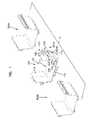
- FIG. 1is a perspective view of an embodiment of a trough system shown in exploded form.
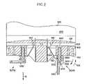
- FIG. 2is a cross-sectional view of the portion of the coupler of FIG. 1 .
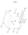
- FIG. 3is a perspective view of a trough member of the trough system of FIG. 1 .
- the terms “couple” and “coupled”mean to join or attach a first element in relation to a second element, whether the attachment is made directly with the second element or indirectly through one or more intermediate components.
- the term “slot”means a space defined by one or more surfaces and can include, without limitation, T-slots, closed slots, flanges, and projections.
- FIG. 1shows an example trough system 10 including a coupler 100 for interconnecting trough members 300 A, 300 B.
- Coupler 100includes locking elements 507 A, 507 B. Additional locking elements can be provided on the opposite and bottom sides of coupler 100 .
- Locking elements 507 A, 507 Bare used to secure the connection between coupler 100 and trough members 300 A, 300 B.
- coupler 100can be configured to release the connections between coupler 100 and trough members 300 A, 300 B.
- locking elements 507 A, 507 Bare tool-less (i.e., do not require the use of a separate tool to couple and uncouple trough members 300 A, 300 B to coupler 100 ).
- elements requiring one or more auxiliary toolsare also within the scope of the present disclosure.
- coupler 100includes a first guiding surface 101 and a second guiding surface 102 at least partially surrounding first guiding surface 101 , as well as a first coupler end 110 and a second coupler end 111 .
- a spacing 103is defined between first guiding surface 101 and second guiding surface 102 .
- Spacing 103is sized to receive a trough member (e.g., trough members 300 A, 300 B) or another trough system component inserted into the spacing 103 in a longitudinal direction 190 .
- First guiding surface 101 of coupler 100is generally in the shape of a trough, including a first side wall portion 104 and a second side wall portion 105 , as well as a bottom wall portion 106 joining first and second side wall portions 104 and 105 .
- the term “trough”means any structure that defines an interior in which an element such as an optical cable can be maintained.
- Second guiding surface 102is also in the shape of a trough.
- a midpoint or midsection 175divides coupler 100 into first and second halves, and generally surrounds at least a portion of first guiding surface 101 .
- a rib portion 166is coupled to second guiding surface 102 .
- Locking elements 507 A, 507 Bare coupled to second guiding surface 102 , as described below.
- locking elements 507 A, 507 Bare shown.
- locking element 507 Ais in the unlocked position
- locking element 507 Bis in the locked position.
- Locking elements 507 A, 507 Beach include a locking portion 510 , a member 520 , and a handle member 530 .
- locking portion 510includes a first portion 532 coupled to member 520 , so that locking portion 510 can slide along member 520 .
- Locking portion 510also includes a second portion 534 that extends towards spacing 103 of coupler 100 .
- a free end of second portion 534forms a point 512 that can extend into spacing 103 and engage trough members 300 A, 300 B, as described further below.
- Member 520is connected at a first end 542 to coupler 100 .
- Member 520is connected at a second end 544 to handle member 530 .
- Handle member 530is pivotally connected to second end 544 of member 520 . Handle member 530 pivots in directions 601 , 602 between locked and unlocked positions, as described below. As handle member 530 pivots to the locked position in direction 601 , a bottom portion 552 contacts and pivots about an outer surface 152 of coupler 100 . In addition, bottom portion 552 of handle member 530 contacts and moves first portion 532 of locking portion 510 along member 520 towards spacing 103 so that point 512 enters spacing 103 . Likewise, when handle member 530 pivots to the unlocked position in direction 602 , bottom portion 552 releases first portion 532 of locking portion 510 so that locking portion 510 moves along member 520 so that point 512 moves out of spacing 103 .
- handle member 530can be moved from locked (locking element 507 B) to unlocked (locking element 507 A) positions.
- locking portion 510In the locked position, locking portion 510 includes end 512 that extends into spacing 103 of coupler 100 to engage a trough member that is inserted therein.
- locking portion 510moves in a direction E to the unlocked position so that point 512 of member 510 is removed from spacing 103 to disengage a trough member positioned therein.
- trough member 300 Ais shown in more detail.
- the phrase “trough member”is used to refer to any trough, fitting, railway, raceway, or similarly configured component including any number of ends. Although a specific embodiment of a trough member is shown in and described herein, other trough members can also be used.
- Trough member 300 Aincludes a first terminal end 302 and a second terminal end 303 .
- Trough member 300 Ais generally in the shape of a trough including first and second side walls 305 , 306 coupled by a bottom wall 307 , thereby defining an interior surface 308 and an exterior surface 309 .
- Walls 305 , 306 , 307are each generally planar.
- exterior surface 309 of trough member 300 Adefines one or more slots 310 on the side walls 305 and 306 and bottom wall 307 .
- terminal ends 302 , 303 of the trough members 300 A, 300 Bare slidingly engaged in direction 190 within the spacing 103 between the first and second guiding surfaces 101 and 102 of coupler 100 .
- the thickness of the walls of each of trough members 300 A, 300 B, or the distance between interior and exterior surfaces 308 , 309are sized to fit within spacing 103 of coupler 100 .
- Coupler 100overlaps terminal ends 302 , 303 of each of trough members 300 A, 300 B to form the coupling, the overlap defining an overlap region.
- Handle member 530is pivoted to the locked position in direction 601 , so that bottom portion 552 of handle member 530 contacts and moves first portion 532 of locking portion 510 along member 520 towards spacing 103 so that point 512 digs into exterior surface 309 of trough member 300 A to resist movement of trough member 300 A in a direction opposite of direction 190 out of coupler 100 .
- handle member 530can be moved into the locked position prior to trough member 300 A being inserted into spacing 103 .
- exterior surface 309 of trough member 300 Arides along point 512 of locking portion 510 until trough member 300 A is fully inserted into coupler 100 to connect coupler 100 to trough member 300 A.
- trough member 300 Acan be inserted into spacing 103 , and thereafter handle member 530 can be moved from the unlocked to the locked position to connect coupler 100 to trough member 300 A.
- handle member 530is moved in direction 602 to the unlocked position. This causes point 512 of locking portion 510 to move out of spacing 103 . As point 512 moves out of spacing 103 , point 512 disengages exterior surface 309 of trough member 300 A, and trough member 300 A can be removed from coupler 100 in the direction opposite to that of direction 190 .
- the locking elements disclosed hereinare tool-less in that the locking elements do not require a separate tool to move the locking elements from the locked position to the unlocked position and vice versa.
- the locking elementscan be moved from the locked position to the unlocked position through use of the user's hand.
- the locking elements disclosed hereinare auto-locking, in that the locking elements can be placed in the locked position prior to insertion of the trough member into the coupler. When the trough member is introduced into the coupler, the locking elements automatically lock the trough member to the coupler. The locking elements can subsequently be moved to the unlocked position to release the trough member from the coupler.
- a couplercan be configured to be coupled to more than two trough members, therefore including more than the first and second coupler ends. Further, a greater number of locking elements can be presented for each coupler end, or, alternatively, fewer locking elements such as, for example, two on opposing sides, can be used. Other configurations are possible.
Landscapes
- Engineering & Computer Science (AREA)
- Architecture (AREA)
- Civil Engineering (AREA)
- Structural Engineering (AREA)
- Laying Of Electric Cables Or Lines Outside (AREA)
Abstract
Description
Claims (1)
Priority Applications (1)
| Application Number | Priority Date | Filing Date | Title |
|---|---|---|---|
| US11/677,174US7584929B2 (en) | 2007-02-21 | 2007-02-21 | Coupler for cable trough |
Applications Claiming Priority (1)
| Application Number | Priority Date | Filing Date | Title |
|---|---|---|---|
| US11/677,174US7584929B2 (en) | 2007-02-21 | 2007-02-21 | Coupler for cable trough |
Publications (2)
| Publication Number | Publication Date |
|---|---|
| US20080199250A1 US20080199250A1 (en) | 2008-08-21 |
| US7584929B2true US7584929B2 (en) | 2009-09-08 |
Family
ID=39706790
Family Applications (1)
| Application Number | Title | Priority Date | Filing Date |
|---|---|---|---|
| US11/677,174Active2027-11-16US7584929B2 (en) | 2007-02-21 | 2007-02-21 | Coupler for cable trough |
Country Status (1)
| Country | Link |
|---|---|
| US (1) | US7584929B2 (en) |
Cited By (3)
| Publication number | Priority date | Publication date | Assignee | Title |
|---|---|---|---|---|
| US20090107696A1 (en)* | 2007-10-26 | 2009-04-30 | Panduit Corp. | Cable Pathway System |
| CN102679041A (en)* | 2011-03-10 | 2012-09-19 | 抚顺欧柏丽电器成套制造有限公司 | Wholly raised, stretched and stamped type cable tightening hook bracket for naval vessels and oceanographic engineering |
| CN103335171A (en)* | 2013-05-07 | 2013-10-02 | 河北京冀防爆电器仪表有限公司 | High polymer anti-corrosion cable bridge |
Families Citing this family (2)
| Publication number | Priority date | Publication date | Assignee | Title |
|---|---|---|---|---|
| CN102789032B (en)* | 2011-05-20 | 2015-07-29 | 邓长霖 | The web member of trough of communication cable |
| CN102996901A (en)* | 2012-10-11 | 2013-03-27 | 苏州爱知电机有限公司 | Slot-type cable support |
Citations (87)
| Publication number | Priority date | Publication date | Assignee | Title |
|---|---|---|---|---|
| GB549840A (en) | 1941-09-08 | 1942-12-09 | Arthur Harry Stevens | Improvements in conduits for electric cables |
| US2316166A (en) | 1940-09-04 | 1943-04-13 | Nat Electric Prod Corp | Wiring duct |
| US2360159A (en) | 1942-11-06 | 1944-10-10 | Wm Burchenal | Conduit connector |
| US2741499A (en) | 1951-08-18 | 1956-04-10 | Kelek Company | Raceway fitting providing access opening |
| US2821154A (en) | 1949-06-18 | 1958-01-28 | Jr James D Tennison | Couplings for joining lengths of trough gutters |
| US2823056A (en) | 1954-10-20 | 1958-02-11 | T J Cope Inc | Connecting means for cable-supporting trough systems and the like |
| US2834622A (en) | 1954-12-15 | 1958-05-13 | T J Cope Inc | Connecting means for cable-supporting trough systems and the like |
| US2880887A (en) | 1955-04-28 | 1959-04-07 | Buckeye Steel Castings Co | Retaining means for coupler carrier |
| US2891750A (en) | 1956-10-01 | 1959-06-23 | Gen Electric | Cable supporting system |
| US3022972A (en) | 1959-07-21 | 1962-02-27 | Burndy Corp | Supporting trough |
| US3042351A (en) | 1960-05-27 | 1962-07-03 | Bois Marvin A Du | Cable trays |
| US3188030A (en) | 1961-12-11 | 1965-06-08 | Fischer Arthur | Clamp or hanger for cables and the like |
| FR1479341A (en) | 1967-07-31 | |||
| US3351699A (en) | 1965-03-19 | 1967-11-07 | Danzer Metal Works Co | Raceway for electrical cables and wires adapted to retain rf energy |
| US3370121A (en) | 1967-06-26 | 1968-02-20 | Danzer Metal Works Co | Rf energy retaining raceway for communications cables |
| US3457598A (en) | 1968-08-09 | 1969-07-29 | Thomas & Betts Corp | Self-clinching bundling strap |
| US3471629A (en) | 1963-03-12 | 1969-10-07 | Ray O Leary | Electrical surface raceway wiring system |
| US3493917A (en) | 1967-08-01 | 1970-02-03 | Viking Industries | Connector locking means |
| US3603625A (en) | 1970-05-18 | 1971-09-07 | Textron Inc | Trenchduct connector units |
| GB1342085A (en) | 1971-04-19 | 1973-12-25 | Simplex Power Centre Ltd | |
| US3782420A (en) | 1971-04-14 | 1974-01-01 | Tehalit Kunststoffwerk Gmbh | Cable installation conduit with l and t joints |
| US3875618A (en)* | 1973-12-10 | 1975-04-08 | Fastway Fasteners | Bundling tie |
| US3915420A (en) | 1974-10-07 | 1975-10-28 | Crouse Hinds Co | Cable tray |
| US4099749A (en) | 1974-04-08 | 1978-07-11 | Air-O-Mulder B.V. | Coupling sleeve |
| US4305236A (en) | 1980-01-14 | 1981-12-15 | Williams Robert F | Rain gutter system |
| DE3636412A1 (en) | 1986-10-25 | 1988-04-28 | Bettermann Obo Ohg | Connecting device for cable ducts (cable channels) |
| EP0315023A2 (en) | 1987-11-03 | 1989-05-10 | Swifts Of Scarborough Limited | Improvements relating to cable tray systems |
| US4854665A (en) | 1984-09-17 | 1989-08-08 | Endot Industries, Inc. | Coupling for joining axial sections of duct for fiber optic cables |
| US4954015A (en)* | 1990-04-04 | 1990-09-04 | Gsw Inc. | Gutter seal |
| US5035092A (en) | 1990-08-13 | 1991-07-30 | Gsw Inc. | Nonsymmetrical eavestrough fitting |
| US5038528A (en)* | 1990-05-08 | 1991-08-13 | Gsw Inc. | Gasket seal |
| US5067678A (en) | 1989-07-31 | 1991-11-26 | Adc Telecommunications, Inc. | Optic cable management system |
| US5078530A (en) | 1991-04-26 | 1992-01-07 | Permanent Solution Industries, Inc. | Plastic coupling device for connecting two building elements |
| US5100221A (en) | 1990-01-22 | 1992-03-31 | Porta Systems Corp. | Optical fiber cable distribution frame and support |
| US5134250A (en) | 1991-04-10 | 1992-07-28 | Panduit Corp. | Wiring duct |
| US5142606A (en) | 1990-01-22 | 1992-08-25 | Porta Systems Corp. | Optical fiber cable distribution frame and support |
| US5161580A (en) | 1990-08-27 | 1992-11-10 | Tyton Corporation | Cable duct fitting with removable cover |
| EP0571307A1 (en) | 1992-05-22 | 1993-11-24 | Max Petit | Self-assembly of cable duct pieces and method of manufacture |
| US5316243A (en) | 1989-07-31 | 1994-05-31 | Adc Telecommunications, Inc. | Optic cable management |
| USD348651S (en) | 1991-04-01 | 1994-07-12 | Adc Telecommunications, Inc. | Fiber trough coupling |
| EP0486442B1 (en) | 1990-11-13 | 1995-10-04 | TELEPLAST S.r.L. | A system of modular supports made up of three or more pieces, suitable for receiving ducts of different diameters |
| US5469893A (en) | 1993-12-21 | 1995-11-28 | Panduit Corp. | Tab and slot fiber optic fitting |
| US5547307A (en) | 1993-12-10 | 1996-08-20 | Legrand | Device for butt-jointing perforated cable tray sections |
| US5617678A (en) | 1992-08-28 | 1997-04-08 | Gsw Inc. | Eavestrough system |
| US5720567A (en) | 1995-04-19 | 1998-02-24 | Sigma-Aldrich Company | Cable tray system |
| US5752781A (en) | 1997-03-14 | 1998-05-19 | Adc Telecommunications, Inc. | Fiber trough coupling |
| US5753855A (en) | 1994-11-17 | 1998-05-19 | Panduit Corp. | Wiring duct fittings |
| US5792993A (en) | 1997-04-07 | 1998-08-11 | Sigma-Aldrich Company | Wireway sealing device |
| EP0874260A1 (en) | 1997-04-21 | 1998-10-28 | Polva Pipelife B.V. | Duct system, coupling, and also method for manufacturing a duct system |
| USD402263S (en) | 1996-12-06 | 1998-12-08 | Panduit Corp. | Straight single raceway fitting |
| USD402262S (en) | 1996-12-06 | 1998-12-08 | Panduit Corp. | Straight dual raceway fitting |
| WO1999006746A1 (en) | 1997-08-01 | 1999-02-11 | Metal Deploye S.A. | Wire cable rack equipped with at least one fixing accessory, and corresponding fixing accessory |
| USD413306S (en) | 1998-06-04 | 1999-08-31 | Panduit Corp. | Right angle single raceway fitting |
| US5995699A (en) | 1998-01-05 | 1999-11-30 | The Wiremold Company | Fiber optic cable raceway system cross reference to related applications |
| US5998732A (en) | 1998-01-13 | 1999-12-07 | Panduit Corp. | Raceway outlet station |
| USD419962S (en) | 1998-01-13 | 2000-02-01 | Panduit Corp. | Raceway outlet station |
| US6037543A (en) | 1994-11-17 | 2000-03-14 | Panduit Corp. | Wiring duct fittings |
| USD430543S (en) | 2000-02-07 | 2000-09-05 | Panduit Corp. | Raceway cover |
| EP1033800A1 (en) | 1999-03-03 | 2000-09-06 | Panduit Corporation | Wireway system having a pivotable cover |
| US6126122A (en) | 1997-11-06 | 2000-10-03 | Sioux Chief Manufacturing Co., Inc. | Double ratchet arm pipe clamp |
| US6143984A (en) | 1998-04-02 | 2000-11-07 | Tyco Electronics Corporation | Adjustable channel connector for a cable raceway system |
| WO2000075550A1 (en) | 1999-06-02 | 2000-12-14 | Warren & Brown Manufacturing Pty. Ltd. | Hollow member connector |
| US6188024B1 (en) | 1998-02-03 | 2001-02-13 | Aparellaje Electrico, S.A. | Elbow for the angular connection of two stretches of raceway for electrical cable system |
| US6193434B1 (en) | 1996-07-26 | 2001-02-27 | Metal Deploye S.A. | Connecting splice for cable trough sections, and resulting cable trough sections |
| EP1160950A2 (en) | 2000-06-01 | 2001-12-05 | Panduit Corp. | Cable duct coupler with locking clip |
| EP1160949A2 (en) | 2000-06-01 | 2001-12-05 | Panduit Corporation | Split fiber cover and raceway fitting |
| US20020006312A1 (en) | 2000-07-12 | 2002-01-17 | Legrand And Legrand Snc | Trunking connecting device |
| WO2002018991A1 (en) | 2000-08-28 | 2002-03-07 | Telect, Inc. | Fiber transition trough coupling system |
| WO2002031939A1 (en) | 2000-10-13 | 2002-04-18 | Alan Dick & Co. Ltd. | Cable tray |
| WO2002033445A2 (en) | 2000-08-28 | 2002-04-25 | Telect, Inc. | Fiber trough coupling system |
| US20020096606A1 (en) | 2000-06-01 | 2002-07-25 | Bernard William A. | Cable duct coupler |
| US6454485B2 (en) | 1999-03-10 | 2002-09-24 | Adaptive Engineering Lab, Inc. | Bi-directional retainer |
| US6463631B2 (en) | 2000-05-17 | 2002-10-15 | Kitagawa Industries Co., Inc. | Binding tool |
| EP1249912A1 (en) | 2001-04-13 | 2002-10-16 | Vergokan | Cable-trough joint |
| WO2002086576A1 (en) | 2001-04-25 | 2002-10-31 | Adc Telecommunications, Inc. | Articulated trough system for communication cables |
| DE10212285A1 (en) | 2001-05-15 | 2002-11-21 | Barad Systems Gmbh | Cable channel corner piece has between two first or second channel parts, hinge and in at least second or first channel part, plate piece |
| US6512875B1 (en) | 2000-10-06 | 2003-01-28 | Adc Telecommunications, Inc. | Optical cable troughs, fittings, and couplings |
| US6520192B1 (en) | 2001-11-14 | 2003-02-18 | Albert Chong-Jen Lo | Extensible positioning device of the shank of an umbrella |
| US6603073B2 (en) | 2001-09-12 | 2003-08-05 | Adc Telecommunications, Inc. | Snap together cable trough system |
| US20030147690A1 (en) | 2000-03-20 | 2003-08-07 | Roennquist Lennart | Connection device, box and clamp |
| US20030177628A1 (en)* | 2002-02-21 | 2003-09-25 | Mark Viklund | Cable ducting joiner |
| US20030183732A1 (en) | 2002-03-27 | 2003-10-02 | Adc Telecommunications, Inc. | Coupler for cable trough |
| US6634825B2 (en) | 2000-09-18 | 2003-10-21 | Bluefin Robotics Corporation | Apparatus for joining cylindrical sections |
| WO2004006400A1 (en) | 2002-07-03 | 2004-01-15 | Richard John Thompson | Trunking and coupling means therefor |
| US6709186B2 (en)* | 2001-11-16 | 2004-03-23 | Adc Telecommunications, Inc. | Coupler for cable trough |
| US6810191B2 (en) | 2001-07-20 | 2004-10-26 | Adc Telecommunications, Inc. | Cable trough cover |
| US7029195B2 (en) | 2002-03-27 | 2006-04-18 | Adc Telecommunications, Inc. | Coupler for cable trough |
Family Cites Families (3)
| Publication number | Priority date | Publication date | Assignee | Title |
|---|---|---|---|---|
| US6097543A (en)* | 1992-02-07 | 2000-08-01 | I-O Display Systems Llc | Personal visual display |
| TW425275B (en)* | 1998-01-07 | 2001-03-11 | Specialties Const | Foot mat |
| US6136122A (en)* | 1998-11-09 | 2000-10-24 | Ford Motor Company | Method of making a glass panel assembly |
- 2007
- 2007-02-21USUS11/677,174patent/US7584929B2/enactiveActive
Patent Citations (101)
| Publication number | Priority date | Publication date | Assignee | Title |
|---|---|---|---|---|
| FR1479341A (en) | 1967-07-31 | |||
| US2316166A (en) | 1940-09-04 | 1943-04-13 | Nat Electric Prod Corp | Wiring duct |
| GB549840A (en) | 1941-09-08 | 1942-12-09 | Arthur Harry Stevens | Improvements in conduits for electric cables |
| US2360159A (en) | 1942-11-06 | 1944-10-10 | Wm Burchenal | Conduit connector |
| US2821154A (en) | 1949-06-18 | 1958-01-28 | Jr James D Tennison | Couplings for joining lengths of trough gutters |
| US2741499A (en) | 1951-08-18 | 1956-04-10 | Kelek Company | Raceway fitting providing access opening |
| US2823056A (en) | 1954-10-20 | 1958-02-11 | T J Cope Inc | Connecting means for cable-supporting trough systems and the like |
| US2834622A (en) | 1954-12-15 | 1958-05-13 | T J Cope Inc | Connecting means for cable-supporting trough systems and the like |
| US2880887A (en) | 1955-04-28 | 1959-04-07 | Buckeye Steel Castings Co | Retaining means for coupler carrier |
| US2891750A (en) | 1956-10-01 | 1959-06-23 | Gen Electric | Cable supporting system |
| US3022972A (en) | 1959-07-21 | 1962-02-27 | Burndy Corp | Supporting trough |
| US3042351A (en) | 1960-05-27 | 1962-07-03 | Bois Marvin A Du | Cable trays |
| US3188030A (en) | 1961-12-11 | 1965-06-08 | Fischer Arthur | Clamp or hanger for cables and the like |
| US3471629A (en) | 1963-03-12 | 1969-10-07 | Ray O Leary | Electrical surface raceway wiring system |
| US3351699A (en) | 1965-03-19 | 1967-11-07 | Danzer Metal Works Co | Raceway for electrical cables and wires adapted to retain rf energy |
| US3370121A (en) | 1967-06-26 | 1968-02-20 | Danzer Metal Works Co | Rf energy retaining raceway for communications cables |
| US3493917A (en) | 1967-08-01 | 1970-02-03 | Viking Industries | Connector locking means |
| US3457598A (en) | 1968-08-09 | 1969-07-29 | Thomas & Betts Corp | Self-clinching bundling strap |
| US3603625A (en) | 1970-05-18 | 1971-09-07 | Textron Inc | Trenchduct connector units |
| US3782420A (en) | 1971-04-14 | 1974-01-01 | Tehalit Kunststoffwerk Gmbh | Cable installation conduit with l and t joints |
| GB1342085A (en) | 1971-04-19 | 1973-12-25 | Simplex Power Centre Ltd | |
| US3875618A (en)* | 1973-12-10 | 1975-04-08 | Fastway Fasteners | Bundling tie |
| US4099749A (en) | 1974-04-08 | 1978-07-11 | Air-O-Mulder B.V. | Coupling sleeve |
| US3915420A (en) | 1974-10-07 | 1975-10-28 | Crouse Hinds Co | Cable tray |
| US4305236A (en) | 1980-01-14 | 1981-12-15 | Williams Robert F | Rain gutter system |
| US4854665A (en) | 1984-09-17 | 1989-08-08 | Endot Industries, Inc. | Coupling for joining axial sections of duct for fiber optic cables |
| DE3636412A1 (en) | 1986-10-25 | 1988-04-28 | Bettermann Obo Ohg | Connecting device for cable ducts (cable channels) |
| EP0315023A2 (en) | 1987-11-03 | 1989-05-10 | Swifts Of Scarborough Limited | Improvements relating to cable tray systems |
| US5316243A (en) | 1989-07-31 | 1994-05-31 | Adc Telecommunications, Inc. | Optic cable management |
| US5067678A (en) | 1989-07-31 | 1991-11-26 | Adc Telecommunications, Inc. | Optic cable management system |
| US5100221A (en) | 1990-01-22 | 1992-03-31 | Porta Systems Corp. | Optical fiber cable distribution frame and support |
| US5142606A (en) | 1990-01-22 | 1992-08-25 | Porta Systems Corp. | Optical fiber cable distribution frame and support |
| US4954015A (en)* | 1990-04-04 | 1990-09-04 | Gsw Inc. | Gutter seal |
| US5038528A (en)* | 1990-05-08 | 1991-08-13 | Gsw Inc. | Gasket seal |
| US5035092A (en) | 1990-08-13 | 1991-07-30 | Gsw Inc. | Nonsymmetrical eavestrough fitting |
| US5161580A (en) | 1990-08-27 | 1992-11-10 | Tyton Corporation | Cable duct fitting with removable cover |
| EP0486442B1 (en) | 1990-11-13 | 1995-10-04 | TELEPLAST S.r.L. | A system of modular supports made up of three or more pieces, suitable for receiving ducts of different diameters |
| USD348651S (en) | 1991-04-01 | 1994-07-12 | Adc Telecommunications, Inc. | Fiber trough coupling |
| US5134250A (en) | 1991-04-10 | 1992-07-28 | Panduit Corp. | Wiring duct |
| US5078530A (en) | 1991-04-26 | 1992-01-07 | Permanent Solution Industries, Inc. | Plastic coupling device for connecting two building elements |
| EP0571307A1 (en) | 1992-05-22 | 1993-11-24 | Max Petit | Self-assembly of cable duct pieces and method of manufacture |
| US5617678A (en) | 1992-08-28 | 1997-04-08 | Gsw Inc. | Eavestrough system |
| US5547307A (en) | 1993-12-10 | 1996-08-20 | Legrand | Device for butt-jointing perforated cable tray sections |
| US5469893A (en) | 1993-12-21 | 1995-11-28 | Panduit Corp. | Tab and slot fiber optic fitting |
| US5753855A (en) | 1994-11-17 | 1998-05-19 | Panduit Corp. | Wiring duct fittings |
| US6037543A (en) | 1994-11-17 | 2000-03-14 | Panduit Corp. | Wiring duct fittings |
| US5720567A (en) | 1995-04-19 | 1998-02-24 | Sigma-Aldrich Company | Cable tray system |
| US6402418B1 (en) | 1996-07-26 | 2002-06-11 | Metal Deploye S.A. | Coupling for assembling cable tray unit sections and cable tray unit sections obtained |
| US6193434B1 (en) | 1996-07-26 | 2001-02-27 | Metal Deploye S.A. | Connecting splice for cable trough sections, and resulting cable trough sections |
| USD402262S (en) | 1996-12-06 | 1998-12-08 | Panduit Corp. | Straight dual raceway fitting |
| USD402263S (en) | 1996-12-06 | 1998-12-08 | Panduit Corp. | Straight single raceway fitting |
| USD447737S1 (en) | 1996-12-06 | 2001-09-11 | Panduit Corp. | Right angle dual raceway fitting |
| US5752781A (en) | 1997-03-14 | 1998-05-19 | Adc Telecommunications, Inc. | Fiber trough coupling |
| US5792993A (en) | 1997-04-07 | 1998-08-11 | Sigma-Aldrich Company | Wireway sealing device |
| EP0874260A1 (en) | 1997-04-21 | 1998-10-28 | Polva Pipelife B.V. | Duct system, coupling, and also method for manufacturing a duct system |
| WO1999006746A1 (en) | 1997-08-01 | 1999-02-11 | Metal Deploye S.A. | Wire cable rack equipped with at least one fixing accessory, and corresponding fixing accessory |
| US6126122A (en) | 1997-11-06 | 2000-10-03 | Sioux Chief Manufacturing Co., Inc. | Double ratchet arm pipe clamp |
| US5995699A (en) | 1998-01-05 | 1999-11-30 | The Wiremold Company | Fiber optic cable raceway system cross reference to related applications |
| US5998732A (en) | 1998-01-13 | 1999-12-07 | Panduit Corp. | Raceway outlet station |
| USD419962S (en) | 1998-01-13 | 2000-02-01 | Panduit Corp. | Raceway outlet station |
| US6188024B1 (en) | 1998-02-03 | 2001-02-13 | Aparellaje Electrico, S.A. | Elbow for the angular connection of two stretches of raceway for electrical cable system |
| US6143984A (en) | 1998-04-02 | 2000-11-07 | Tyco Electronics Corporation | Adjustable channel connector for a cable raceway system |
| USD413306S (en) | 1998-06-04 | 1999-08-31 | Panduit Corp. | Right angle single raceway fitting |
| EP1033800A1 (en) | 1999-03-03 | 2000-09-06 | Panduit Corporation | Wireway system having a pivotable cover |
| US6454485B2 (en) | 1999-03-10 | 2002-09-24 | Adaptive Engineering Lab, Inc. | Bi-directional retainer |
| WO2000075550A1 (en) | 1999-06-02 | 2000-12-14 | Warren & Brown Manufacturing Pty. Ltd. | Hollow member connector |
| USD430543S (en) | 2000-02-07 | 2000-09-05 | Panduit Corp. | Raceway cover |
| US20030147690A1 (en) | 2000-03-20 | 2003-08-07 | Roennquist Lennart | Connection device, box and clamp |
| US6463631B2 (en) | 2000-05-17 | 2002-10-15 | Kitagawa Industries Co., Inc. | Binding tool |
| US20020096606A1 (en) | 2000-06-01 | 2002-07-25 | Bernard William A. | Cable duct coupler |
| US6476327B1 (en) | 2000-06-01 | 2002-11-05 | Panduit Corp. | Split fiber cover and raceway fitting |
| US6523791B2 (en)* | 2000-06-01 | 2003-02-25 | Panduit Corp. | Cable duct coupler |
| EP1160950A2 (en) | 2000-06-01 | 2001-12-05 | Panduit Corp. | Cable duct coupler with locking clip |
| US6634605B2 (en)* | 2000-06-01 | 2003-10-21 | Panduit Corp. | Cable duct coupler |
| US6450458B1 (en)* | 2000-06-01 | 2002-09-17 | Panduit Corp. | Cable duct coupler with locking clip |
| EP1160949A2 (en) | 2000-06-01 | 2001-12-05 | Panduit Corporation | Split fiber cover and raceway fitting |
| US20020006312A1 (en) | 2000-07-12 | 2002-01-17 | Legrand And Legrand Snc | Trunking connecting device |
| WO2002033445A2 (en) | 2000-08-28 | 2002-04-25 | Telect, Inc. | Fiber trough coupling system |
| WO2002018991A1 (en) | 2000-08-28 | 2002-03-07 | Telect, Inc. | Fiber transition trough coupling system |
| US6424779B1 (en)* | 2000-08-28 | 2002-07-23 | Steven W. Ellison | Fiber trough coupling system |
| US6634825B2 (en) | 2000-09-18 | 2003-10-21 | Bluefin Robotics Corporation | Apparatus for joining cylindrical sections |
| US6512875B1 (en) | 2000-10-06 | 2003-01-28 | Adc Telecommunications, Inc. | Optical cable troughs, fittings, and couplings |
| WO2002031939A1 (en) | 2000-10-13 | 2002-04-18 | Alan Dick & Co. Ltd. | Cable tray |
| EP1249912A1 (en) | 2001-04-13 | 2002-10-16 | Vergokan | Cable-trough joint |
| WO2002086576A1 (en) | 2001-04-25 | 2002-10-31 | Adc Telecommunications, Inc. | Articulated trough system for communication cables |
| DE10212285A1 (en) | 2001-05-15 | 2002-11-21 | Barad Systems Gmbh | Cable channel corner piece has between two first or second channel parts, hinge and in at least second or first channel part, plate piece |
| US6810191B2 (en) | 2001-07-20 | 2004-10-26 | Adc Telecommunications, Inc. | Cable trough cover |
| US6603073B2 (en) | 2001-09-12 | 2003-08-05 | Adc Telecommunications, Inc. | Snap together cable trough system |
| US6520192B1 (en) | 2001-11-14 | 2003-02-18 | Albert Chong-Jen Lo | Extensible positioning device of the shank of an umbrella |
| US20040159750A1 (en) | 2001-11-16 | 2004-08-19 | Adc Telecommunications, Inc. | Coupler for cable trough |
| US7175137B2 (en) | 2001-11-16 | 2007-02-13 | Adc Telecommunications, Inc. | Coupler for cable trough |
| US6709186B2 (en)* | 2001-11-16 | 2004-03-23 | Adc Telecommunications, Inc. | Coupler for cable trough |
| US20030177628A1 (en)* | 2002-02-21 | 2003-09-25 | Mark Viklund | Cable ducting joiner |
| US7093997B2 (en) | 2002-03-27 | 2006-08-22 | Adc Telecommunications, Inc. | Coupler for cable trough |
| US6715719B2 (en) | 2002-03-27 | 2004-04-06 | Adc Telecommunications, Inc. | Coupler for cable trough |
| US7029195B2 (en) | 2002-03-27 | 2006-04-18 | Adc Telecommunications, Inc. | Coupler for cable trough |
| US20030183731A1 (en) | 2002-03-27 | 2003-10-02 | Ferris Matthew D. | Coupler for cable trough |
| US20060210356A1 (en) | 2002-03-27 | 2006-09-21 | Adc Telecommunications, Inc. | Coupler for Cable Trough |
| US20060261240A1 (en) | 2002-03-27 | 2006-11-23 | Adc Telecommunications, Inc. | Coupler for Cable Trough |
| US20030183732A1 (en) | 2002-03-27 | 2003-10-02 | Adc Telecommunications, Inc. | Coupler for cable trough |
| WO2004006400A1 (en) | 2002-07-03 | 2004-01-15 | Richard John Thompson | Trunking and coupling means therefor |
Non-Patent Citations (15)
| Title |
|---|
| Exhibit A, Ditel, Inc.; Ditel UPL-1000/UPT-1000/Corner Cable Guides; product information, 2 pages, (C) 1986. |
| Exhibit B, ADC Telecommunications, Inc.; FiberGuide(TM), Fiber Management System, 6 pages front and back printed, 16/1989. |
| Exhibit C, Warren & Brown Technologies Pty. Ltd., Fibre Optic Management Systems, Component Selection Guide, 19 pages of product information. Source: www.warrenandbrown.com.au (admitted prior art as of the filing date). |
| Exhibit D, Panduit Network Connectivity Group, FiberRunner(TM) 6x4 Routing System Product Brochure, 2 pages, (C) Panduit Corp. 2000. |
| Exhibit E, Panduit Corp. FiberRunner(TM) 4x4 Quiklock(TM) Coupler (FRBC4X4) Customer Drawing, 1 page, Jul. 13, 2001. |
| Exhibit F, Panduit Corp. FiberRunner(TM) 6x4 Quiklock(TM) Coupler (FRBC6X4) Customer Drawing, 1 page, May 10, 2000. |
| Exhibit G, Panduit Corp. FiberRunner(TM) 12x4 Quiklock(TM) Coupler (FRBC12X4) Customer Drawing, 1 page, Jan. 3, 2001. |
| Exhibits H-Y, Photographs of various Panduit products (admitted prior art as of the filing date). |
| U.S. Appl. No. 11/425,625, filed Jun. 21, 2006. |
| U.S. Appl. No. 11/677,181, filed Feb. 21, 2007. |
| U.S. Appl. No. 11/677,184, filed Feb. 21, 2007. |
| U.S. Appl. No. 11/677,188, filed Feb. 21, 2007. |
| U.S. Appl. No. 11/677,193, filed Feb. 21, 2007. |
| U.S. Appl. No. 11/677,200, filed Feb. 21, 2007. |
| U.S. Appl. No. 11/677,203, filed Feb. 21, 2007. |
Cited By (4)
| Publication number | Priority date | Publication date | Assignee | Title |
|---|---|---|---|---|
| US20090107696A1 (en)* | 2007-10-26 | 2009-04-30 | Panduit Corp. | Cable Pathway System |
| CN102679041A (en)* | 2011-03-10 | 2012-09-19 | 抚顺欧柏丽电器成套制造有限公司 | Wholly raised, stretched and stamped type cable tightening hook bracket for naval vessels and oceanographic engineering |
| CN102679041B (en)* | 2011-03-10 | 2016-09-28 | 抚顺欧柏丽实业股份有限公司 | Integration embossment stretching and punching type cable tight-hook bracket for naval vessels and ocean engineering |
| CN103335171A (en)* | 2013-05-07 | 2013-10-02 | 河北京冀防爆电器仪表有限公司 | High polymer anti-corrosion cable bridge |
Also Published As
| Publication number | Publication date |
|---|---|
| US20080199250A1 (en) | 2008-08-21 |
Similar Documents
| Publication | Publication Date | Title |
|---|---|---|
| US20190064467A1 (en) | Coupler for Cable Trough | |
| US7896295B2 (en) | Coupler for cable trough | |
| US9356436B2 (en) | Cable trough system and method | |
| US8256723B2 (en) | Cable routing devices with integrated couplers | |
| US8254744B2 (en) | Cable trough system and method | |
| US7614817B2 (en) | Coupler for cable trough | |
| US8444095B2 (en) | Coupler for cable trough | |
| US7584929B2 (en) | Coupler for cable trough | |
| US7815152B2 (en) | Coupler for cable trough | |
| US7493005B2 (en) | Coupler for cable trough | |
| US7481597B2 (en) | Coupler for cable trough | |
| US7504583B2 (en) | Coupler for cable trough | |
| US7463809B2 (en) | Coupler for cable trough | |
| US20080197243A1 (en) | Coupler for Cable Trough |
Legal Events
| Date | Code | Title | Description |
|---|---|---|---|
| AS | Assignment | Owner name:ADC TELECOMMUNICATIONS, INC., MINNESOTA Free format text:ASSIGNMENT OF ASSIGNORS INTEREST;ASSIGNOR:FERRIS, MATTHEW D.;REEL/FRAME:018918/0758 Effective date:20070220 | |
| STCF | Information on status: patent grant | Free format text:PATENTED CASE | |
| FPAY | Fee payment | Year of fee payment:4 | |
| AS | Assignment | Owner name:TYCO ELECTRONICS SERVICES GMBH, SWITZERLAND Free format text:ASSIGNMENT OF ASSIGNORS INTEREST;ASSIGNOR:ADC TELECOMMUNICATIONS, INC.;REEL/FRAME:036060/0174 Effective date:20110930 | |
| AS | Assignment | Owner name:COMMSCOPE EMEA LIMITED, IRELAND Free format text:ASSIGNMENT OF ASSIGNORS INTEREST;ASSIGNOR:TYCO ELECTRONICS SERVICES GMBH;REEL/FRAME:036956/0001 Effective date:20150828 | |
| AS | Assignment | Owner name:COMMSCOPE TECHNOLOGIES LLC, NORTH CAROLINA Free format text:ASSIGNMENT OF ASSIGNORS INTEREST;ASSIGNOR:COMMSCOPE EMEA LIMITED;REEL/FRAME:037012/0001 Effective date:20150828 | |
| AS | Assignment | Owner name:JPMORGAN CHASE BANK, N.A., AS COLLATERAL AGENT, ILLINOIS Free format text:PATENT SECURITY AGREEMENT (TERM);ASSIGNOR:COMMSCOPE TECHNOLOGIES LLC;REEL/FRAME:037513/0709 Effective date:20151220 Owner name:JPMORGAN CHASE BANK, N.A., AS COLLATERAL AGENT, ILLINOIS Free format text:PATENT SECURITY AGREEMENT (ABL);ASSIGNOR:COMMSCOPE TECHNOLOGIES LLC;REEL/FRAME:037514/0196 Effective date:20151220 Owner name:JPMORGAN CHASE BANK, N.A., AS COLLATERAL AGENT, IL Free format text:PATENT SECURITY AGREEMENT (ABL);ASSIGNOR:COMMSCOPE TECHNOLOGIES LLC;REEL/FRAME:037514/0196 Effective date:20151220 Owner name:JPMORGAN CHASE BANK, N.A., AS COLLATERAL AGENT, IL Free format text:PATENT SECURITY AGREEMENT (TERM);ASSIGNOR:COMMSCOPE TECHNOLOGIES LLC;REEL/FRAME:037513/0709 Effective date:20151220 | |
| FPAY | Fee payment | Year of fee payment:8 | |
| AS | Assignment | Owner name:COMMSCOPE, INC. OF NORTH CAROLINA, NORTH CAROLINA Free format text:RELEASE BY SECURED PARTY;ASSIGNOR:JPMORGAN CHASE BANK, N.A.;REEL/FRAME:048840/0001 Effective date:20190404 Owner name:ALLEN TELECOM LLC, ILLINOIS Free format text:RELEASE BY SECURED PARTY;ASSIGNOR:JPMORGAN CHASE BANK, N.A.;REEL/FRAME:048840/0001 Effective date:20190404 Owner name:COMMSCOPE TECHNOLOGIES LLC, NORTH CAROLINA Free format text:RELEASE BY SECURED PARTY;ASSIGNOR:JPMORGAN CHASE BANK, N.A.;REEL/FRAME:048840/0001 Effective date:20190404 Owner name:REDWOOD SYSTEMS, INC., NORTH CAROLINA Free format text:RELEASE BY SECURED PARTY;ASSIGNOR:JPMORGAN CHASE BANK, N.A.;REEL/FRAME:048840/0001 Effective date:20190404 Owner name:ANDREW LLC, NORTH CAROLINA Free format text:RELEASE BY SECURED PARTY;ASSIGNOR:JPMORGAN CHASE BANK, N.A.;REEL/FRAME:048840/0001 Effective date:20190404 Owner name:ANDREW LLC, NORTH CAROLINA Free format text:RELEASE BY SECURED PARTY;ASSIGNOR:JPMORGAN CHASE BANK, N.A.;REEL/FRAME:049260/0001 Effective date:20190404 Owner name:COMMSCOPE TECHNOLOGIES LLC, NORTH CAROLINA Free format text:RELEASE BY SECURED PARTY;ASSIGNOR:JPMORGAN CHASE BANK, N.A.;REEL/FRAME:049260/0001 Effective date:20190404 Owner name:COMMSCOPE, INC. OF NORTH CAROLINA, NORTH CAROLINA Free format text:RELEASE BY SECURED PARTY;ASSIGNOR:JPMORGAN CHASE BANK, N.A.;REEL/FRAME:049260/0001 Effective date:20190404 Owner name:REDWOOD SYSTEMS, INC., NORTH CAROLINA Free format text:RELEASE BY SECURED PARTY;ASSIGNOR:JPMORGAN CHASE BANK, N.A.;REEL/FRAME:049260/0001 Effective date:20190404 Owner name:ALLEN TELECOM LLC, ILLINOIS Free format text:RELEASE BY SECURED PARTY;ASSIGNOR:JPMORGAN CHASE BANK, N.A.;REEL/FRAME:049260/0001 Effective date:20190404 | |
| AS | Assignment | Owner name:JPMORGAN CHASE BANK, N.A., NEW YORK Free format text:ABL SECURITY AGREEMENT;ASSIGNORS:COMMSCOPE, INC. OF NORTH CAROLINA;COMMSCOPE TECHNOLOGIES LLC;ARRIS ENTERPRISES LLC;AND OTHERS;REEL/FRAME:049892/0396 Effective date:20190404 Owner name:JPMORGAN CHASE BANK, N.A., NEW YORK Free format text:TERM LOAN SECURITY AGREEMENT;ASSIGNORS:COMMSCOPE, INC. OF NORTH CAROLINA;COMMSCOPE TECHNOLOGIES LLC;ARRIS ENTERPRISES LLC;AND OTHERS;REEL/FRAME:049905/0504 Effective date:20190404 Owner name:WILMINGTON TRUST, NATIONAL ASSOCIATION, AS COLLATE Free format text:PATENT SECURITY AGREEMENT;ASSIGNOR:COMMSCOPE TECHNOLOGIES LLC;REEL/FRAME:049892/0051 Effective date:20190404 Owner name:WILMINGTON TRUST, NATIONAL ASSOCIATION, AS COLLATERAL AGENT, CONNECTICUT Free format text:PATENT SECURITY AGREEMENT;ASSIGNOR:COMMSCOPE TECHNOLOGIES LLC;REEL/FRAME:049892/0051 Effective date:20190404 | |
| FEPP | Fee payment procedure | Free format text:MAINTENANCE FEE REMINDER MAILED (ORIGINAL EVENT CODE: REM.); ENTITY STATUS OF PATENT OWNER: LARGE ENTITY | |
| FEPP | Fee payment procedure | Free format text:11.5 YR SURCHARGE- LATE PMT W/IN 6 MO, LARGE ENTITY (ORIGINAL EVENT CODE: M1556); ENTITY STATUS OF PATENT OWNER: LARGE ENTITY | |
| MAFP | Maintenance fee payment | Free format text:PAYMENT OF MAINTENANCE FEE, 12TH YEAR, LARGE ENTITY (ORIGINAL EVENT CODE: M1553); ENTITY STATUS OF PATENT OWNER: LARGE ENTITY Year of fee payment:12 | |
| AS | Assignment | Owner name:WILMINGTON TRUST, DELAWARE Free format text:SECURITY INTEREST;ASSIGNORS:ARRIS SOLUTIONS, INC.;ARRIS ENTERPRISES LLC;COMMSCOPE TECHNOLOGIES LLC;AND OTHERS;REEL/FRAME:060752/0001 Effective date:20211115 | |
| AS | Assignment | Owner name:APOLLO ADMINISTRATIVE AGENCY LLC, NEW YORK Free format text:SECURITY INTEREST;ASSIGNORS:ARRIS ENTERPRISES LLC;COMMSCOPE TECHNOLOGIES LLC;COMMSCOPE INC., OF NORTH CAROLINA;AND OTHERS;REEL/FRAME:069889/0114 Effective date:20241217 | |
| AS | Assignment | Owner name:RUCKUS WIRELESS, LLC (F/K/A RUCKUS WIRELESS, INC.), NORTH CAROLINA Free format text:RELEASE OF SECURITY INTEREST AT REEL/FRAME 049905/0504;ASSIGNOR:JPMORGAN CHASE BANK, N.A., AS COLLATERAL AGENT;REEL/FRAME:071477/0255 Effective date:20241217 Owner name:COMMSCOPE TECHNOLOGIES LLC, NORTH CAROLINA Free format text:RELEASE OF SECURITY INTEREST AT REEL/FRAME 049905/0504;ASSIGNOR:JPMORGAN CHASE BANK, N.A., AS COLLATERAL AGENT;REEL/FRAME:071477/0255 Effective date:20241217 Owner name:COMMSCOPE, INC. OF NORTH CAROLINA, NORTH CAROLINA Free format text:RELEASE OF SECURITY INTEREST AT REEL/FRAME 049905/0504;ASSIGNOR:JPMORGAN CHASE BANK, N.A., AS COLLATERAL AGENT;REEL/FRAME:071477/0255 Effective date:20241217 Owner name:ARRIS SOLUTIONS, INC., NORTH CAROLINA Free format text:RELEASE OF SECURITY INTEREST AT REEL/FRAME 049905/0504;ASSIGNOR:JPMORGAN CHASE BANK, N.A., AS COLLATERAL AGENT;REEL/FRAME:071477/0255 Effective date:20241217 Owner name:ARRIS TECHNOLOGY, INC., NORTH CAROLINA Free format text:RELEASE OF SECURITY INTEREST AT REEL/FRAME 049905/0504;ASSIGNOR:JPMORGAN CHASE BANK, N.A., AS COLLATERAL AGENT;REEL/FRAME:071477/0255 Effective date:20241217 Owner name:ARRIS ENTERPRISES LLC (F/K/A ARRIS ENTERPRISES, INC.), NORTH CAROLINA Free format text:RELEASE OF SECURITY INTEREST AT REEL/FRAME 049905/0504;ASSIGNOR:JPMORGAN CHASE BANK, N.A., AS COLLATERAL AGENT;REEL/FRAME:071477/0255 Effective date:20241217 |