US7584808B2 - Centralizer-based survey and navigation device and method - Google Patents
Centralizer-based survey and navigation device and methodDownload PDFInfo
- Publication number
- US7584808B2 US7584808B2US11/302,384US30238405AUS7584808B2US 7584808 B2US7584808 B2US 7584808B2US 30238405 AUS30238405 AUS 30238405AUS 7584808 B2US7584808 B2US 7584808B2
- Authority
- US
- United States
- Prior art keywords
- centralizers
- metrology
- centralizer
- csn
- csn device
- Prior art date
- Legal status (The legal status is an assumption and is not a legal conclusion. Google has not performed a legal analysis and makes no representation as to the accuracy of the status listed.)
- Active, expires
Links
Images


Classifications
- E—FIXED CONSTRUCTIONS
- E21—EARTH OR ROCK DRILLING; MINING
- E21B—EARTH OR ROCK DRILLING; OBTAINING OIL, GAS, WATER, SOLUBLE OR MELTABLE MATERIALS OR A SLURRY OF MINERALS FROM WELLS
- E21B47/00—Survey of boreholes or wells
- E21B47/02—Determining slope or direction
- E21B47/022—Determining slope or direction of the borehole, e.g. using geomagnetism
- E—FIXED CONSTRUCTIONS
- E21—EARTH OR ROCK DRILLING; MINING
- E21B—EARTH OR ROCK DRILLING; OBTAINING OIL, GAS, WATER, SOLUBLE OR MELTABLE MATERIALS OR A SLURRY OF MINERALS FROM WELLS
- E21B17/00—Drilling rods or pipes; Flexible drill strings; Kellies; Drill collars; Sucker rods; Cables; Casings; Tubings
- E21B17/10—Wear protectors; Centralising devices, e.g. stabilisers
- E21B17/1057—Centralising devices with rollers or with a relatively rotating sleeve
Definitions
- the present inventionrelates, but is not limited, to a method and apparatus for accurately determining in three dimensions information on the location of an object in a passageway and/or the path taken by a passageway, e.g., a borehole or tube.
- the drilling industryhas recognized the desirability of having a position determining system that can be used to guide a drilling head to a predestined target location.
- a position determining systemthat can provide accurate position information on the path of a borehole and/or the location of a drilling head at any given time as the drill pipe advances.
- the position determining systemwould be small enough to fit into a drill pipe so as to present minimal restriction to the flow of drilling or returning fluids and accuracy should be as high as possible.
- Some shallow depth position location systemsare based on tracking sounds or electromagnetic radiation emitted by a sonde near the drilling head. In addition to being depth limited, such systems are also deficient in that they require a worker to carry a receiver and walk the surface over the drilling head to detect the emissions and track the drilling head location. Such systems cannot be used where there is no worker access to the surface over the drilling head or the ground is not sufficiently transparent to the emissions.
- the '628 patent systemconstructs on a segment-by-segment basis, circular arc data representing the path of the borehole and which also represents, at each measurement point, the location of the measuring strain gauge sensors. If the sensors are positioned near the drilling head, the location of the drilling head can be obtained.
- the '628 patent system and methodhas application for directional drilling and can be used with various types of drilling apparatus, for example, rotary drilling, water jet drilling, down hole motor drilling, and pneumatic drilling.
- the systemis useful in directional drilling such as well drilling, reservoir stimulation, gas or fluid storage, routing of original piping and wiring, infrastructure renewal, replacement of existing pipe and wiring, instrumentation placement, core drilling, cone penetrometer insertion, storage tank monitoring, pipe jacking, tunnel boring and in other related fields.
- the '628 patentalso provides a method for compensating for rotation of the measuring tube during a drilling operation by determining, at each measurement position, information concerning the net amount of rotation relative to a global reference, if any, of the measuring tube as it passes through the passageway and using the rotation information with the strain measurement to determine the azimuth associated with a measured local radius of curvature relative to the global reference.
- the Centralizer-based Survey and Navigation (CSN) deviceis designed to provide borehole or passageway position information.
- the deviceis suitable for both closed traverse surveying (referred to as survey) and open traverse surveying or navigation while drilling (referred to as navigation).
- the CSN devicecan consist of a sensor string comprised of one or more segments having centralizers, which position the segment(s) within the passageway, and at least one metrology sensor, which measures the relative positions and orientation of the centralizers, even with respect to gravity.
- the CSN devicecan also have at least one odometry sensor, an initialization system, and a navigation algorithm implementing processor(s).
- the number of centralizers in the sensor stringshould be at least three. Additional sensors, such as inclinometers, accelerometers, and others can be included in the CSN device and system.
- each segmentcan have its own detector to measure relative positions of centralizers, its own detector that measures relative orientation of the sensor string with respect to gravity, and/or where the partial data reduction is performed by a processor placed inside the segment and high value data is communicated to the navigation algorithm processor through a bus.
- Another exemplary embodimentrelates to a CSN device utilizing a sensor string segment which can utilize capacitance proximity detectors and/or fiber optic proximity detectors and/or strain gauges based proximity detectors that measure relative positions of centralizers with respect to a reference straight metrology body or beam.
- Another exemplary embodimentrelates to a CSN device utilizing an angular metrology sensor, which has rigid beams as sensor string segments that are attached to one or more centralizers. These beams are connected to each other using a flexure-based joint with strain gauge instrumented flexures and/or a universal joint with an angle detector such as angular encoder. The relative positions of the centralizers are determined based on the readings of the said encoders and/or strain gauges.
- Another exemplary embodimentrelates to a CSN device utilizing a strain gauge instrumented bending beam as a sensor string segment, which can use the readings of these strain gauges to measure relative positions of the centralizers.
- Another exemplary embodimentrelates to a CSN device utilizing a bending beam sensor, which can utilize multiple sets of strain gauges to compensate for possible shear forces induced in the said bending beam.
- Another exemplary embodimentrelates to a compensator for zero drift of detectors measuring orientation of the sensor string and detectors measuring relative displacement of the centralizers by inducing rotation in the sensor string or taking advantage of rotation of a drill string.
- the detector measuring orientation of the sensor stringis an accelerometer
- such a devicecan calculate the zero drift of the accelerometer detector by enforcing that the average of the detector-measured value of local Earth's gravity to be equal to the known value of g at a given time, and/or where the zero drift of detectors measuring relative displacement of the centralizers is compensated for by enforcing that the readings of the strain gauges follow the same angular dependence on the rotation of the string as the angular dependence measured by inclinometers, accelerometers, and or gyroscopes placed on the drill string or sensor string that measure orientation of the sensor string with respect to the Earth's gravity.
- Another exemplary embodimentrelates to a device using buoyancy to compensate for the gravity induced sag of the metrology beam of the proximity-detector-based or angular-metrology-based displacement sensor string.
- Another exemplary embodimentrelates to centralizers that maintain constant separation between their points of contact with the borehole.
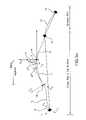
- FIG. 1shows a system incorporating a CSN device in accordance with the invention.
- FIG. 2 a through FIG. 2 eshow various embodiments of a CSN device in accordance with the invention.
- FIG. 3shows a system incorporating a CSN device as shown in FIG. 2 a, in accordance with the invention.
- FIG. 4illustrates a CSN device utilizing a displacement or strain metrology as shown in FIGS. 2 b , 2 c , and 2 e , in accordance with the invention.
- FIGS. 5 a through 5 dshow a global and local coordinate system utilized by a CSN device, in accordance with the invention.
- FIG. 5 bshows an expanded view of the encircled local coordinate system shown in FIG. 5 a.
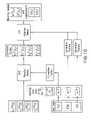
- FIG. 6is a block diagram showing how navigation and/or surveying can be performed by a CSN system/device in accordance with the invention.
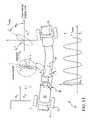
- FIGS. 7 a and 7 bshow a displacement metrology CSN device, in accordance with the invention; FIG. 7 b shows the device of FIG. 7 a through cross section A-A.
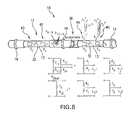
- FIG. 8shows a CSN device utilizing strain gauge metrology sensors in accordance with the invention.
- FIG. 9shows forces acting on a CSN device as shown in FIG. 8 , in accordance with the invention.
- FIG. 10is a block diagram of strain gauge data reduction for a CSN device as shown in FIG. 8 , in accordance with the invention.
- FIG. 11shows strains exhibited in a rotating bending beam of a CSN device in accordance with the invention.
- FIG. 12is a block diagram illustrating how data reduction can be performed in a rotating strain gauge CSN device, such as illustrated in FIG. 11 , in accordance with the invention.
- FIG. 13shows vectors defining sensitivity of an accelerometer used with a CSN device in accordance with the invention.
- FIG. 14is a block diagram showing how data reduction can be performed in an accelerometer used with a CSN device in accordance with the invention.
- FIGS. 15 to 17show a universal joint strain gauge CSN device in accordance with the invention.
- FIG. 18is a block diagram of a CSN assembly in accordance with the invention.
- FIGS. 19 , 20 a , and 20 bshow embodiments of centralizers in accordance with the invention.
- FIGS. 21 a and 21 bshow gravity compensating CSN devices.
- the inventionrelates to a Centralizer-based Survey and Navigation (hereinafter “CSN”) device, system, and methods, designed to provide passageway and down-hole position information.
- CSNCentralizer-based Survey and Navigation
- the CSN devicecan be scaled for use in passageways and holes of almost any size and is suitable for survey of or navigation in drilled holes, piping, plumbing, municipal systems, and virtually any other hole environment.
- passageway and boreholeare used interchangeably.
- FIG. 1shows the basic elements of a directional drilling system incorporating a CSN device 10 , a sensor string 12 including segments 13 and centralizers 14 ( 14 a , 14 b , and 14 c ), a drill string 18 , an initializer 20 , an odometer 22 , a computer 24 , and a drill head 26 .
- a metrology sensor 28is included and can be associated with the middle centralizer 14 b , or located on the drill string 18 .
- the odometer 22 and computer 24 hosting a navigation algorithmare, typically, installed on a drill rig 30 and in communication with the CSN device 10 .
- a CSN device 10may be pre-assembled before insertion into the borehole 16 or may be assembled as the CSN device 10 advances into the borehole 16 .
- the CSN device 10can be placed onto a drill string 18 and advanced into the borehole 16 .
- the centralizers 14 of the CSN device 10which are shown and discussed in greater detail below in relation to FIGS. 19-20 b , are mechanical or electromechanical devices that position themselves in a repeatable fashion in the center of the borehole 16 cross-section, regardless of hole wall irregularities.
- a CSN device 10uses at least three centralizers 14 : a trailing centralizer 14 a , a middle centralizer 14 b , and a leading centralizer 14 c , so named based on direction of travel within the borehole 16 .
- the centralizers 14are connected by along a sensor string 12 in one or more segments 13 , which connect any two centralizers 14 , to maintain a known, constant spacing in the borehole 16 and between the connected centralizers 14 .
- Direction changes of the CSN device 10 evidenced by changes in orientation of the centralizers 14 with respect to each other or with respect to the sensor string 12 segments 13can be used to determine the geometry of borehole 16 .
- the initializer 20shown in FIG. 1 , provides information on the borehole 16 and CSN device 10 insertion orientation with respect to the borehole 16 so that future calculations on location can be based on the initial insertion location.
- the initializer 20has a length that is longer than the distance between a pair of adjacent centralizers 14 on the sensor string segment 13 , providing a known path of travel into the borehole 16 for the CSN device 10 so that it may be initially oriented. Under some circumstances, information about location of as few as two points along the borehole 16 entranceway may be used in lieu of the initializer 20 .
- Navigationin accordance with an exemplary embodiment of the invention provides the position location of the CSN device 10 with respect to its starting position and orientation based on data obtained by using the initializer 20 .
- FIGS. 2 a - 2 ethere are various types of centralizer-based metrologies compatible with the CSN device 10 ; however, all can determine the position of the CSN device 10 based on readings at the CSN device 10 .
- the types of CSN device 10 metrologiesinclude, but are not limited to: (1) straight beam/angle metrology, shown in FIG. 2 a; (2) straight beam/displacement metrology, shown in FIG. 2 b; (3) bending beam metrology, shown in FIG. 2 c; (4) optical beam displacement metrology, shown in FIG. 2 d; and (5) combination systems of (1)-(4), shown in FIG. 2 e .
- the CSN device 10uses this borehole 16 curvature information along with distance traveled along the borehole 16 to determine its location in three dimensions. Distance traveled within the borehole 16 from the entry point to a current CSN device 10 location can be measured with an odometer 22 connected either to the drill string 18 used to advance the CSN device 10 or connected with the CSN device 10 itself.
- the CSN device 10can be in communication with a computer 24 , which can be used to calculate location based on the CSN device 10 measurements and the odometer 22 .
- the CSN device 10itself can include all instrumentation and processing capability to determine its location and the connected computer 24 can be used to display this information.
- a navigation algorithmsuch as that shown in FIG. 6 , can combine the readings of the sensor string segment(s) 12 , the odometry sensor(s) 22 , and the initializer 20 to calculate the borehole 16 position of the CSN device 10 .
- a CSN device 10provides the relative positions of the centralizers 14 . More precisely, an ideal three-centralizer CSN device 10 provides vector coordinates of the leading centralizer 14 c in a local coordinate system, as shown by FIG. 5 b , where the “x” axis is defined by the line connecting the centralizers 14 a and 14 c and the “z” axis lies in a plane defined by the “x” axis and the global vertical “Z.” Alternately, the position of the middle centralizer would be provided in a coordinate system where the “x” axis is defined by the line connecting the centralizers 14 a and 14 b and the “y” axis and “z” axis are defined same as above. Coordinate systems where the x axis connects either leading and trailing centralizers, or leading and middle centralizer, or middle and trailing centralizers, while different in minor details, all lead to mathematically equivalent navigation algorithms and will be used interchangeably.
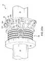
- FIG. 3illustrates a CSN device 10 in accordance with the metrology technique shown in FIG. 2 a , where angle of direction change between the leading centralizer 14 c and trailing centralizer 14 a is measured at the middle centralizer 14 b.
- the CSN device 10follows the drill head 26 through the borehole 16 as it changes direction.
- the magnitude of displacement of the centralizers 14 with respect to each otheris reflected by an angle ⁇ between the beam forming segment 13 connecting the centralizers 14 c and 14 b and the beam forming segment 13 connecting the centralizers 14 b and 14 a , which is measured by angle-sensing detector(s) 29 (a metrology sensor 28 ) at or near the middle centralizer 14 b.
- Rotation ⁇ of the sensor string 12can also be measured.
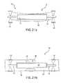
- FIG. 4shows a CSN device 10 configured for an alternative navigation/survey technique reflecting the metrology techniques shown in FIGS. 2 b , 2 c , and 2 e , i.e., both displacement and bending/strain metrology.
- Displacement metrologymeasures relative positions of the centralizers 14 using a straight displacement metrology beam 31 (as a sensor string 12 segment 13 ) that is mounted on the leading and trailing centralizers, 14 c and 14 a.
- Proximity detectors 38(a metrology sensor 28 ) measure the position of the middle centralizer 14 b with respect to the straight metrology beam 31 .
- strain detector metrologycan also be used in the CSN device 10 , which is configured to measure the strain induced in a solid metrology beam 32 (another form of sensor string segment 12 ) that connects between each of the centralizers 14 . Any deviation of the centralizer 14 positions from a straight line will introduce strains in the beam 32 .
- the strain detectors or gauges 40(a type of metrology sensor 28 ) measure these strains (the terms strain detectors and strain gauges are used interchangeably herein).
- the strain gages 40are designed to convert mechanical motion into an electronic signal.
- the CSN device 10can have as few as two strain gauge instrumented intervals in the beam 32 . Rotation ⁇ of the sensor string 12 can also be measured.
- both strain detectors 40 and proximity detectors 38may be used simultaneously to improve navigation accuracy.
- the displacement metrologyis based on a deviation of the beam of light such as a laser beam.
- a coherent, linear light sourcee.g., laser
- a reflecting surface mounted on trailing centralizer 14 areflects the coherent light back to a position sensitive optical detector (PSD, a metrology sensor 28 ) mounted on middle centralizer 14 b , which converts the reflected location of the coherent light into an electronic signal.
- PSDposition sensitive optical detector
- the point at which the beam intersects the PSD metrology sensor 28is related to the relative displacement of the three centralizers 14 .
- light from a laser mounted on a middle centralizer 14 bis reflected from a mirror mounted on an adjacent centralizer 14 and redirected back to a PSD metrology sensor 28 mounted on the middle centralizer 14 b.
- the point at which the beam intersects the PSD metrology sensor 28is related to the relative angle of the orientation of the centralizers 14 .
- a CSN navigation algorithmuses a local coordinate system (x, y, z) to determine the location of a CSN device 10 in three dimensions relative to a Global coordinate system (X, Y, Z).
- FIG. 5 aindicates the general relationship between the two coordinate systems where the local coordinates are based at a location of CSN device 10 along borehole 16 beneath the ground surface.
- a CSN navigation algorithmcan be based on the following operation of the CSN device 10 : (1) the CSN device 10 is positioned in such a way that the trailing centralizer 14 a and the middle centralizer 14 b are located in a surveyed portion (the known part) of the borehole 16 and the leading centralizer 14 c is within an unknown part of the borehole 16 ; (2) using displacement metrology, a CSN device 10 comprises a set of detectors, e.g., metrology sensor 28 , that calculates the relative displacement of the centralizers 14 with respect to each other in the local coordinate system; (3) a local coordinate system is defined based on the vector connecting centralizers 14 a and 14 c (axis “x” in FIG.
- the position of the leading centralizer 14 ccan be determined.
- An algorithm as shown in FIG. 6 applied by, e.g., a processor, and functioning in accordance with the geometry of FIG. 5 ccan perform as follows: (1) the CSN device 10 is positioned as indicated in the preceding paragraph; (2) the relative angular orientations ⁇ y , ⁇ z and positions (y, z) of any two adjacent sensor string segments 13 of a CSN device 10 in the local coordinate system are determined using internal CSN device 10 segment 13 detectors; (3) three centralizers 14 are designated to be the leading 14 c , trailing 14 a , and middle 14 b centralizers of the equivalent or ideal three-centralizer CSN device 10 ; (4) relative positions of the leading, middle, and trailing centralizers 14 forming an ideal CSN device 10 are determined in the local coordinate system of the sensor string 12 .
- FIG. 7 ashows a CSN device 10 according to an alternative exemplary embodiment of the invention that utilizes straight beam displacement (such as shown in FIGS. 2 b and 4 ) and capacitance measurements as metrology sensors 28 to calculate the respective locations of the centralizers 14 a , 14 b , and 14 c.
- a stiff straight beam 31is attached to the leading and trailing centralizers 14 c and 14 a by means of flexures 33 that are stiff in radial direction and flexible about the axial direction ( ⁇ ).
- a set of proximity detectors, 38can be associated with the middle centralizer 14 b. The proximity detectors 38 measure the displacement of the middle centralizer 14 b with respect to the straight beam 31 .
- An accelerometer 36can be used to measure the orientation of the middle centralizer 14 b with respect to the vertical.
- Examples of proximity detectorsinclude, capacitance, eddy current, magnetic, strain gauge, and optical proximity detectors.
- the Global and Local coordinate systems ( FIGS. 5 a - 5 d ) associated with the CSN device 10 of this embodimentare shown in FIG. 7 a.
- FIG. 7 bThe relationship between these proximity detectors 38 and the straight beam 31 is shown in FIG. 7 b as a cross-sectional view of the CSN device 10 of FIG. 7 a taken through the center of middle centralizer 14 b.
- the proximity detectors 38measure position of the middle centralizer 14 b in the local coordinate system as defined by the vectors connecting leading and trailing centralizers 14 a and 14 c and the vertical.
- the CSN device 10 as shown in FIGS. 7 a and 7 bcan have an electronics package, which can include data acquisition circuitry supporting all detectors, including proximity detectors 38 , strain gauges 40 ( FIG. 8 ), inclinometers (e.g., the accelerometer 36 ), etc., and power and communication elements (not shown).
- d horizontal and d verticalare displacements in the vertical and orthogonal planes defined earlier
- d z and d yare the displacements measured by the capacitance detectors 38
- ⁇is the angle of rotation of the capacitance detectors 38 with respect to the vertical as determined by the accelerometer(s) 36 .
- the centralizer 14 coordinates in the local (x, y, z) coordinate systemare:
- the direction of vector u 2is known in the global coordinate system (X, Y, Z) since the trailing and middle centralizers are located in the known part of the borehole. Therefore, the orientations of axes x, y, and z of the local coordinate system, in the global coordinate system (X, Y, Z) are:
- Calculating u 3 in the global coordinate systemprovides one with the information of the position of the leading centralizer 14 c and expands the knowledge of the surveyed borehole 16 .
- FIG. 8shows a CSN device 10 with strain gauge detectors 40 attached to a bending beam 32 .
- the circuit design associated with the resistance strain gauges 40 and accelerometer(s) 36is shown below the CSN device 10 .
- Any type of strain detector 40 and orientation detector, e.g., accelerometer 36may be used.
- Each instrumented sensor string 12 segment 13 , here the bending beam 32 (between centralizers 14 ) of the CSN device 10can carry up to four, or more, sets of paired strain gauge detectors 40 (on opposite sides of the bending beam 32 ), each opposing pair forming a half-bridge.
- segments 13may or may not be the same segments 13 that accommodate the capacitance detector 38 if the CSN device 10 utilizes such.
- strain gauge detector 40 and accelerometer 36 readingscan be recorded simultaneously.
- a displacement detector supporting odometry correction ( ⁇ l)can also be placed on at least one segment 13 (not shown).
- Several temperature detectorscan also be placed on each segment 13 to permit compensation for thermal effects.
- strain detector 40 pairsbe mounted onto each sensor string segment 13 (between centralizers 14 ) as the minimum number of strain detectors 40 .
- the circuit diagrams shown below the CSN device 10with voltage outputs V z 1 , V y 1 , V z 2 , and V y 2 , represent an exemplary wiring of these half-bridges.
- These detectors 40can provide the relative orientation and relative position of the leading centralizer 14 c with respect to the trailing centralizer 14 a , or a total of four variables.
- At least one of the adjacent sensor string segments 13 between centralizers 14should contain a detector (not shown) that can detect relative motion of the CSN device 10 with respect to the borehole 16 to determine the actual borehole 16 length when the CSN device 10 and drill string 18 are advanced therein.
- the variation of curvatures of the beam 32likely cannot be achieved without some shear forces applied to centralizers 14 .
- the preferred strain gauge detector 40 scheme of the CSN device 10 shown in FIG. 8accounts for these shear forces.
- the exemplary circuit layout shown below the CSN device 10 and corresponding chartshows how the sensors 40 can be connected.
- FIG. 9illustrates two dimensional resultant shear forces acting on centralizers 14 of a single sensor string segment 13 comprised of a bending bean 32 as shown in FIG. 8 .
- Four unknown variablesnamely, two forces and two bending moments, should satisfy two equations of equilibrium: the total force and the total moment acting on the bending beam 32 are equal to zero.
- FIG. 9shows the distribution of shear force ( T ) and moments ( M ) along the length of bending beam 32 . The values are related in the following bending equation:
- ⁇is the angle between the orientation of the beam 32 and the horizontal
- Eis the Young Modulus of the beam 32 material
- Iis the moment of inertia
- Lis the length of the segment 12 as determined by the locations of centralizers 14 .
- the orientation of the points along the axis of the segment 12 in each of two directions (y, z) perpendicular to the axis of the beam (x)may be described such that the relative angular orientation of the end points of the segment 12 with respect to each other can be represented by integrating over the length of the segment:
- the values of the strain gauge outputsare known, the values of the moments (M) can be determined by solving the preceding Eq. 9. The solution will be:
- FIG. 10shows a block diagram for data reduction in a strain gauge CSN device 10 , such as that shown in FIG. 9 .
- Torsion load correctionhas a general form:
- the thermal loadschange the values of factors p i ⁇ .
- the valuesare described by: p j Correctd ⁇ (1+ CTE X ⁇ T ) ⁇ p j ⁇ p j Correctd ⁇ (1+ CTE ⁇ ⁇ T ) ⁇ p j ⁇ (Eq. 20)
- the CTE'sare calibration parameters. They include both material and material stiffness thermal dependences.
- strain gauge detectors 40can be placed on an axially rotating beam 32 constrained at the centralizers 14 by fixed immovable borehole 16 walls forming a sensor string segment 12 .
- Advantages in greater overall measurement accuracy from CSN device 10 that may be gained by rotating the beam 32 to create a time varying signal related to the amount of bending to which it is subjectedmay result from, but are not limited to, signal averaging over time to reduce the effects of noise in the signal and improved discrimination bending direction.
- ⁇ ⁇ ( ⁇ )[ sin ⁇ ⁇ ⁇ cos ⁇ ⁇ ⁇ ] ⁇ [ cos ⁇ ⁇ ⁇ sin ⁇ ⁇ ⁇ - sin ⁇ ⁇ ⁇ cos ⁇ ⁇ ⁇ ] ⁇ [ ⁇ z ⁇ y ] + ⁇ offset ( Eq . ⁇ 23 ) where ⁇ z and ⁇ y are strain caused by bending correspondingly in the “xz” and “yz” planes indicated in FIG. 11 .
- the values of the ⁇ z and ⁇ ymay be recovered by first performing a least square fit of ⁇ ( ⁇ ) into sine and cosine.
- One of the possible proceduresis to first determine values of ⁇ sin , ⁇ cos , and ⁇ offset by solving equations:
- Eq . ⁇ 26[ cos ⁇ ⁇ ⁇ - sin ⁇ ⁇ ⁇ sin ⁇ ⁇ ⁇ cos ⁇ ⁇ ⁇ ] ⁇ [ ⁇ sin ⁇ cos ] ( Eq . ⁇ 26 )
- the matrix in Eq. 26is an orientation matrix that must be determined by calibrated experiments for each sensor string segment 12 .
- index irefers to the measurement number
- ⁇ a and ⁇ bare the Gauge Orientation Angles in FIG. 12 and Eq. 29.
- the Gauge Orientation Angles shown in FIG. 12are determined by calibrated experiments for each sensor string segment 12 .
- FIG. 13which relates to the accelerometer 36 described above as incorporated into the CSN device 10 electronics package as discussed in relation to FIGS. 7 a and 8 .
- a tri-axial accelerometer 36can be fully described by the following data where, relative to the Global vertical direction “Z,” each component of the accelerometer has a calibrated electrical output (Gauge factor), a known, fixed spatial direction relative to the other accelerometer 36 components (Orientation), and a measured angle of rotation about its preferred axis of measurement (Angular Location):
- rotation matricesmay be defined as:
- the readings of the accelerometer 36 located on the circumference of a CSN device 10can be determined as:
- a data reduction algorithmcorrects accelerometer 36 readings for zero offset drift and angular velocity.
- Such an algorithmcan be used by a zero drift compensator, including a processor, with a CSN device 10 as shown in FIG. 11 , for example.
- the zero drift compensatorworks by rotating the CSN device 10 .
- a zero drift compensatorcan operate by enforcing a rule that the average of the measured value of g be equal to the know value of g at a given time.
- a zero drift compensatorcan operate by enforcing a rule that the strain readings of the strain gauges 40 follow the same angular dependence on the rotation of the string 12 as the angular dependence recorded by the accelerometers 36 .
- a zero drift compensatorcan operate by enforcing a rule that the strain readings of the strain gauges 40 follow a same angular dependence as that measured by angular encoders placed on the drill string 18 ( FIG. 1 ) or sensor string 12 .
- Equation 35can be solved for the angles.
- the solutionhas a form:
- Equation 37The notation may be simplified if one defines variables, as follows:
- V i 1d 1 X ⁇ a i X + d 1 Y ⁇ a i Y + d 1 Z ⁇ a i Z
- V i 2d 2 X ⁇ a i X + d 2 Y ⁇ a i Y + d 2 Z ⁇ a i Z
- ⁇ 2⁇ ( ⁇ V i l ⁇ t ) 2 + ( ⁇ V i 2 ⁇ t ) 2 cos 2 ⁇ ( ⁇ i ) ⁇ ⁇ ( ⁇ V i 1 ⁇ t ) 2 + ( ⁇ V i 2 ⁇ t ) 2 1 - ( V i 3 ) 2 ⁇ ( ⁇ V i 1 ⁇ t ) 2 + ( ⁇ V i 2 ⁇ t ) 2 ( Eq . ⁇ 40 )
- offsets OF 1 , OF 2 , OF 3are determined by the least square fit, i.e., by minimizing, as follows:
- the rotation anglecan be defined as:
- FIGS. 15-17each of which shows a universal joint angle measurement sensor 50 , which is an alternative embodiment to the strain gauge displacement CSN device 10 embodiments discussed above in relation to, e.g., FIGS. 2 c and 8 .
- the universal joint 50can be cylindrical in shape to fit in a borehole 16 or tube and is comprised of two members 56 joined at two sets of opposing bendable flexures 54 such that the joint 50 may bend in all directions in any plane orthogonal to its length.
- the bendable flexures 54are radially positioned with respect to an imaginary center axis of the universal joint 50 .
- Each one of the two sets of bendable flexures 54allows for flex in the joint 50 along one plane along the imaginary center axis.
- Each plane of flexis orthogonal to the other, thus allowing for flex in all directions around the imaginary center axis.
- the strain forces at the bendable flexures 54are measured in much the same way as those on the strain gauge detectors 40 of the CSN device 10 of FIG. 8 using detectors 52 .
- Spatial orientation of universal joint 50 relative to the verticalmay be measured by a tri-axial accelerometer 57 attached to the interior of universal joint 50 .
- the universal joint 50may be connected to a middle centralizer 14 b of a CSN device 10 as shown in FIG. 16 .
- a spring 58can be used to activate the centralizer 14 b (this will be explained in further detail below with reference to FIGS. 19-20 b ).
- the universal joint 50 and middle centralizer 14 bare rigidly attached to each other and connected with arms 44 to leading and trailing centralizers 14 a and 14 c.
- the universal joint 50when located on a CSN device 10 for use as a downhole tool for survey and/or navigation, is positioned at or near a middle centralizer 14 b of three centralizers 14 .
- the two outer centralizers 14 a and 14 care connected to the universal joint 50 by arms 44 , as shown in FIG. 17 , which may house electronics packages if desired.
- the universal joint 50includes strain gauges 52 ( FIG. 15 ) to measure the movement of the joint members 56 and arms 44 .
- the CSN device 10 of the various embodiments of the inventionis used for the survey of boreholes 16 or passageways and navigation of downhole devices; the goal of the navigation algorithm ( FIG. 6 ) is to determine relative positions of the centralizers 14 of the CSN device 10 and to determine the borehole 16 location of the CSN device 10 based on that data.
- FIG. 18which is a block diagram of the assembly of a CSN device 10
- the first local coordinate system (# 1 )has coordinate vectors as follows:
- strain gaugese.g., 52 as shown in FIG. 15
- the reading of strain gauges, e.g., 52 as shown in FIG. 15provide the angles ⁇ y , ⁇ z of the CSN device 10 segment leading centralizer 14 c position in the local coordinate system.
- the origin of the next coordinate system and the next centralizer 14 bwould be:
- r ⁇ i + 1r ⁇ i + X ⁇ i ⁇ ( L i - 2 3 ⁇ y i 2 + z i 2 L i ) + Y ⁇ i ⁇ y i + Z ⁇ i ⁇ z ( Eq . ⁇ 45 )
- Eq. 45 and 46one can define the origin and the orientation of the CSN device 10 portion in the unknown region of a borehole 16 in the first local coordinate system. After applying equations 45 and 46 to all CSN device 10 segments 13 , the location of the CSN device 10 portion in the unknown region of a borehole 16 is determined.
- the shape of the CSN device 10is defined up to the accuracy of the strain gauges 40 or 52 .
- the inclination of the CSN device 10 with respect to the verticalis defined within the accuracy of the accelerometers 36 or 57 .
- the azimuth orientation of the CSN device 10is not known.
- centralizers 14are used to accurately and repeatably position the metrology sensors 28 ( FIG. 1 ) discussed above within a borehole 16 .
- the centralizer 14has a known pivot point 60 that will not move axially relative to the metrology article to which it is attached.
- the centralizer 14is configured to adapt straight line mechanisms to constrain the centralizer 14 pivot point 60 to axially remain in the same lateral plane. This mechanism, sometimes referred to as a “Scott Russell” or “Evan's” linkage, is composed of two links, 64 as shown in FIG. 19 , and 64 a and 64 b as shown in FIGS.
- the shorter link 64 b of FIGS. 20 a and 20 bhas a fixed pivot point 60 b
- the longer link 64 ahas a pivot point 60 a free to move axially along the tube housing 34 .
- the links 64 a and 64 bare joined at a pivot point 66 , located half-way along the length of the long link 64 a , while the short link 64 b is sized so that the distance from the fixed point 60 b to the linked pivot 66 is one half the length of the long link 64 a.
- This centralizer 14 mechanismis formed by placing a spring 68 behind the sliding pivot point 60 a , which provides an outward forcing load on the free end of the long link 64 a.
- This designcan use roller bearings at pivot points, but alternatively they could be made by other means, such as with a flexure for tighter tolerances, or with pins in holes if looser tolerances are allowed.
- a roller 62is positioned at the end of the long link 64 a to contact the borehole 16 wall.
- FIG. 19shows a centralizer 14 embodiment with a double roller, fixed pivot point 60 .
- This embodimenthas two spring-loaded 68 rollers 62 centered around a fixed pivot point 60 .
- FIGS. 20 a and 20 bhave a single roller structure, also with a single fixed pivot point 60 , but with one spring-loaded 68 roller 62 .
- a deviceis utilized for canceling the effects of gravity on a mechanical beam to mitigate sag.
- a deviceis utilized for canceling the effects of gravity on a mechanical beam to mitigate sag.
- FIGS. 21 a and 21 busing buoyancy to compensate for gravity-induced sag of a metrology beam of a CSN device 10 having a proximity-detector-based or angular-metrology-based displacement sensor string, accuracy of the survey or navigation can be improved.
- an angle measuring metrology sensor CSN device 10can enclose the sensor string segments 13 within a housing 34 containing a fluid 81 . This fluid 81 provides buoyancy for the segments 13 , thus mitigating sag.
- FIG. 21 aan angle measuring metrology sensor CSN device 10 can enclose the sensor string segments 13 within a housing 34 containing a fluid 81 . This fluid 81 provides buoyancy for the segments 13 , thus mitigating sag.
- FIG. 21 aan angle measuring metrology
- a displacement measuring metrology sensor CSN device 10can likewise encase its straight beam 31 within a fluid 81 filled housing 34 . In this way, sagging of the straight beam 31 is mitigated and with it errors in displacement sensing by the capacitor sensor 38 are prevented.
Landscapes
- Engineering & Computer Science (AREA)
- Geology (AREA)
- Life Sciences & Earth Sciences (AREA)
- Mining & Mineral Resources (AREA)
- Physics & Mathematics (AREA)
- General Life Sciences & Earth Sciences (AREA)
- Fluid Mechanics (AREA)
- Environmental & Geological Engineering (AREA)
- Geochemistry & Mineralogy (AREA)
- Geophysics (AREA)
- Mechanical Engineering (AREA)
- Length Measuring Devices With Unspecified Measuring Means (AREA)
- Testing Or Calibration Of Command Recording Devices (AREA)
- Geophysics And Detection Of Objects (AREA)
- Navigation (AREA)
Abstract
Description
dhorizontal=dzcos φ+dysin φ
dvertical=−dzsin φ+dycos φ (Eq. 1)
where uiare position of the leading (i=3), trailing(i=1) and middle (i=2)
ūx=
ūy=
ūs=
Calculating u3in the global coordinate system provides one with the information of the position of the leading
Where θ is the angle between the orientation of the
The values of the integrals are independent of the values of the applied moments and both integrals are positive numbers. Thus, these equations (Eqs. 6 and 7) can be combined and rewritten as:
θ=M1·Int1θ+M2·Int2θ (Eq. 8)
where Int1θ and Int2θ are calibration constants for a given
where I1and I2are moments of inertia of corresponding cross-section (of
which may also be rewritten as:
M1=m1,1·ε1+m1,2·ε2
M2=m2,1·ε1+m2,2·ε2 (Eq. 11)
where mi,jare calibration constants. Substitution of Eq. 11 into Eq. 8 gives:
θ=ε1·(Int1θ·m1,1+Int2θ·m2,1)+ε2·(Int1θ·m1,2+Int2θ·m2,2) (Eq. 12)
y=M1·Int1y+M2·Int2y (Eq. 14)
and also
y=ε1·(Int1y·m1,1+Int2y·m2,1)+ε2·(Int1y·m1,2+Int2y·m2,2) (Eq. 15)
Int1i +Int2y=L·Int1θ (Eq. 16)
which may be used to simplify device calibration.
y=ε1Y·p1Y+ε2Y·p2Y
z=ε1Z·p1Z+ε2Z·p2Z
θY=ε1Y·p1Yθ+ε2Y·p2Yθ
θZ=ε1Z·p1Zθ+ε2Z·p2Zθ (Eq. 18)
where coefficients piα are determined during calibration. These coefficients are referred to as the 4×4 Influence Matrix in
where τ is the torsion applied to a
pj
pj
The CTE's are calibration parameters. They include both material and material stiffness thermal dependences. Each value of piα has its own calibrated linear dependence on the axial strain loads, as follows:
pj
pj
The correction factors described in the previous two equations of Eq. 21 are referred to as Correction Factors in
ε(φ)=εmaxsin(φ−φm−ψ)=εsinsin(φ)+εcoscos(φ)+εoffset (Eq. 22)
where φ and φmare defined in
where εzand εyare strain caused by bending correspondingly in the “xz” and “yz” planes indicated in
where:
The values of εyand εzcan be recovered from:
The matrix in Eq. 26 is an orientation matrix that must be determined by calibrated experiments for each
ε(φ)=(εmax+error)·sin(φ−φm−ψ)+offset (Eq. 27)
Correspondingly, εYand εZare determined by solving the least square fit into equations Eq. 26, where:
where indexes a and b refer to the two bridges (of
| Gauge | Angular | |||
| factor | Location | Orientation | ||
| Accelerometer X | mV/g | ψyz | NX, NY, NZ | ||
| Accelerometer Y | mV/g | ψyz | NX, NY, NZ | ||
| Accelerometer Z | mV/g | ψyz | NX, NY, NZ | ||
where fit parameters c0, c1, and c2are determined during initial calibration of the
aα=c0α·g·sin(θ)+g·cos(θ)·(c1α·sin(φ)+c2α·cos(φ))+offα+c3α·ω2 (Eq. 35)
where off is the zero offset of the accelerometer, ω is the angular velocity of rotation, and index α refers to the local x, y, and z coordinate system. Equation 35 can be solved for the angles. The solution has a form:
The values of the twelve constants djα are determined during calibration.
cos2(θ)·sin2(φ)+cos2(θ)·cos2(φ)+sin2(θ)=1 (Eq. 37)
The notation may be simplified if one defines variables, as follows:
where index i refers to each measurement performed by the accelerometers. Note that offsets OF1, OF2, OF3are independent of measurements and do not have index i. Consistency condition Eq. 37 can be rewritten as:
(Vi1−OF1−d1ω·ω2)2+(Vi2−OF2−d2ω·ω2)2+(Vi3−OF3−d3ω·ω2)2=1 (Eq. 39)
where cosθ is determined by the
Claims (6)
Priority Applications (2)
| Application Number | Priority Date | Filing Date | Title |
|---|---|---|---|
| US11/302,384US7584808B2 (en) | 2004-12-14 | 2005-12-14 | Centralizer-based survey and navigation device and method |
| US12/542,529US7870912B2 (en) | 2004-12-14 | 2009-08-17 | Centralizer-based survey and navigation device and method |
Applications Claiming Priority (2)
| Application Number | Priority Date | Filing Date | Title |
|---|---|---|---|
| US63547704P | 2004-12-14 | 2004-12-14 | |
| US11/302,384US7584808B2 (en) | 2004-12-14 | 2005-12-14 | Centralizer-based survey and navigation device and method |
Related Child Applications (1)
| Application Number | Title | Priority Date | Filing Date |
|---|---|---|---|
| US12/542,529ContinuationUS7870912B2 (en) | 2004-12-14 | 2009-08-17 | Centralizer-based survey and navigation device and method |
Publications (2)
| Publication Number | Publication Date |
|---|---|
| US20060157278A1 US20060157278A1 (en) | 2006-07-20 |
| US7584808B2true US7584808B2 (en) | 2009-09-08 |
Family
ID=36588509
Family Applications (2)
| Application Number | Title | Priority Date | Filing Date |
|---|---|---|---|
| US11/302,384Active2027-08-29US7584808B2 (en) | 2004-12-14 | 2005-12-14 | Centralizer-based survey and navigation device and method |
| US12/542,529ActiveUS7870912B2 (en) | 2004-12-14 | 2009-08-17 | Centralizer-based survey and navigation device and method |
Family Applications After (1)
| Application Number | Title | Priority Date | Filing Date |
|---|---|---|---|
| US12/542,529ActiveUS7870912B2 (en) | 2004-12-14 | 2009-08-17 | Centralizer-based survey and navigation device and method |
Country Status (5)
| Country | Link |
|---|---|
| US (2) | US7584808B2 (en) |
| EP (1) | EP1831502B1 (en) |
| JP (2) | JP5362994B2 (en) |
| CA (1) | CA2591691C (en) |
| WO (1) | WO2006065923A2 (en) |
Cited By (31)
| Publication number | Priority date | Publication date | Assignee | Title |
|---|---|---|---|---|
| US20090314546A1 (en)* | 2008-06-24 | 2009-12-24 | Mintchev Martin P | In-drilling alignment |
| US20110308332A1 (en)* | 2010-06-21 | 2011-12-22 | The Charles Machine Works, Inc. | Method And System For Monitoring Bend And Torque Forces On A Drill Pipe |
| US8150531B2 (en) | 2008-07-11 | 2012-04-03 | Medtronic, Inc. | Associating therapy adjustments with patient posture states |
| US8175720B2 (en) | 2009-04-30 | 2012-05-08 | Medtronic, Inc. | Posture-responsive therapy control based on patient input |
| US8209028B2 (en) | 2008-07-11 | 2012-06-26 | Medtronic, Inc. | Objectification of posture state-responsive therapy based on patient therapy adjustments |
| US8219206B2 (en) | 2008-07-11 | 2012-07-10 | Medtronic, Inc. | Dwell time adjustments for posture state-responsive therapy |
| US8231555B2 (en) | 2009-04-30 | 2012-07-31 | Medtronic, Inc. | Therapy system including multiple posture sensors |
| US8280517B2 (en) | 2008-09-19 | 2012-10-02 | Medtronic, Inc. | Automatic validation techniques for validating operation of medical devices |
| US8332041B2 (en) | 2008-07-11 | 2012-12-11 | Medtronic, Inc. | Patient interaction with posture-responsive therapy |
| US8388555B2 (en) | 2010-01-08 | 2013-03-05 | Medtronic, Inc. | Posture state classification for a medical device |
| US8396565B2 (en) | 2003-09-15 | 2013-03-12 | Medtronic, Inc. | Automatic therapy adjustments |
| US8401666B2 (en) | 2008-07-11 | 2013-03-19 | Medtronic, Inc. | Modification profiles for posture-responsive therapy |
| CN102141197B (en)* | 2010-01-28 | 2013-03-20 | 杨志雄 | Measuring equipment to explore the direction of the path in the pipe |
| US8437861B2 (en) | 2008-07-11 | 2013-05-07 | Medtronic, Inc. | Posture state redefinition based on posture data and therapy adjustments |
| US8504150B2 (en) | 2008-07-11 | 2013-08-06 | Medtronic, Inc. | Associating therapy adjustments with posture states using a stability timer |
| US8579834B2 (en) | 2010-01-08 | 2013-11-12 | Medtronic, Inc. | Display of detected patient posture state |
| US8708934B2 (en) | 2008-07-11 | 2014-04-29 | Medtronic, Inc. | Reorientation of patient posture states for posture-responsive therapy |
| US20140202014A1 (en)* | 2013-01-22 | 2014-07-24 | Samsung Display Co., Ltd. | Flexible display and method for measuring angle of the same |
| US9050471B2 (en) | 2008-07-11 | 2015-06-09 | Medtronic, Inc. | Posture state display on medical device user interface |
| US9181791B2 (en) | 2011-06-28 | 2015-11-10 | Raytheon Company | System and method for determining soil characteristics and drillstring instability during horizontal directional drilling |
| US20160076359A1 (en)* | 2013-05-02 | 2016-03-17 | 059312 N.B. Inc. | Bipartite sensor array |
| US9327070B2 (en) | 2009-04-30 | 2016-05-03 | Medtronic, Inc. | Medical device therapy based on posture and timing |
| US9357949B2 (en) | 2010-01-08 | 2016-06-07 | Medtronic, Inc. | User interface that displays medical therapy and posture data |
| US9566441B2 (en) | 2010-04-30 | 2017-02-14 | Medtronic, Inc. | Detecting posture sensor signal shift or drift in medical devices |
| US9737719B2 (en) | 2012-04-26 | 2017-08-22 | Medtronic, Inc. | Adjustment of therapy based on acceleration |
| US9907959B2 (en) | 2012-04-12 | 2018-03-06 | Medtronic, Inc. | Velocity detection for posture-responsive therapy |
| US9956418B2 (en) | 2010-01-08 | 2018-05-01 | Medtronic, Inc. | Graphical manipulation of posture zones for posture-responsive therapy |
| US10060807B2 (en) | 2010-06-21 | 2018-08-28 | The Charles Machine Works, Inc. | Method and system for monitoring bend and torque forces on a drill pipe |
| US10221675B2 (en)* | 2013-05-02 | 2019-03-05 | 059312 N.B. Inc. | Cyclical sensor array |
| US10471264B2 (en) | 2005-12-02 | 2019-11-12 | Medtronic, Inc. | Closed-loop therapy adjustment |
| US12281566B2 (en) | 2015-10-06 | 2025-04-22 | Halliburton Energy Services, Inc. | Systems and methods for detecting downhole tool location inside a borehole |
Families Citing this family (29)
| Publication number | Priority date | Publication date | Assignee | Title |
|---|---|---|---|---|
| US7528946B2 (en)* | 2003-03-31 | 2009-05-05 | The Charles Machine Works, Inc. | System for detecting deflection of a boring tool |
| US20090207302A1 (en)* | 2008-02-14 | 2009-08-20 | Chris Neffendorf | Method and apparatus to measure features in a conduit |
| US9803426B2 (en) | 2010-06-18 | 2017-10-31 | Schlumberger Technology Corporation | Flex joint for downhole drilling applications |
| US20140284103A1 (en)* | 2013-03-25 | 2014-09-25 | Schlumberger Technology Corporation | Monitoring System for Drilling Instruments |
| CA2931801C (en)* | 2013-12-31 | 2020-07-21 | Halliburton Energy Services, Inc. | Bend measurements of adjustable motor assemblies using inclinometers |
| CA2928917C (en)* | 2013-12-31 | 2018-08-14 | Gustav Edward LANGE | Bend measurements of adjustable motor assemblies using strain gauges |
| WO2015102599A1 (en) | 2013-12-31 | 2015-07-09 | Halliburton Energy Services, Inc. | Bend measurements of adjustable motor assemblies using magnetometers |
| RU2560762C1 (en)* | 2014-07-23 | 2015-08-20 | Федеральное Государственное Автономное Образовательное Учреждение Высшего Профессионального Образования "Сибирский Федеральный Университет" | Simulator for determination of direction of collared blastholes with reference to bottomhole plane |
| US10094211B2 (en)* | 2014-10-09 | 2018-10-09 | Schlumberger Technology Corporation | Methods for estimating wellbore gauge and dogleg severity |
| AU2015234298B2 (en)* | 2014-10-16 | 2020-07-02 | Imdex Technologies Pty Ltd | Controlled rotation centraliser |
| US9631674B2 (en)* | 2015-04-01 | 2017-04-25 | Halliburton Energy Services, Inc. | Determining the optimal radius of a thrust bearing in a well tool |
| JP6311650B2 (en)* | 2015-06-01 | 2018-04-18 | 住友金属鉱山株式会社 | Grout work simulation device, grout work simulation program, and grout method |
| WO2017087490A1 (en)* | 2015-11-18 | 2017-05-26 | Tony Ross | Bearing section for a positive displacement mud motor for use in directional earth drilling |
| GB2545914A (en)* | 2015-12-30 | 2017-07-05 | Huyton Stuart | Adjustable roller centralizer |
| WO2017181396A1 (en)* | 2016-04-21 | 2017-10-26 | 深圳市樊溪电子有限公司 | Method for calculating bending strain of pipe |
| JP6677576B2 (en)* | 2016-06-03 | 2020-04-08 | 前田建設工業株式会社 | Method and apparatus for estimating position / posture of suspended moving object using acceleration signal |
| CN106950070B (en)* | 2017-03-06 | 2019-06-28 | 河海大学 | Experimental rig for rectangular top pipe jacking construction Whole Process Simulation |
| RU173657U1 (en)* | 2017-04-25 | 2017-09-05 | Егор Александрович Жильцов | Self-centering axis positioning device |
| US11131167B1 (en) | 2017-11-10 | 2021-09-28 | National Technology & Engineering Solutions Of Sandia, Llc | Modular anti-rotation drilling systems and methods |
| US11739629B2 (en)* | 2019-07-31 | 2023-08-29 | Schlumberger Technology Corporation | Strain gauges for detecting deformations of a plate |
| CN110485466B (en)* | 2019-08-08 | 2021-04-20 | 南方工程检测修复技术研究院 | Assembly type recyclable circular working pit with reserved door opening and construction method thereof |
| CN110485470B (en)* | 2019-08-08 | 2021-05-04 | 郑州安源工程技术有限公司 | Rectangular working well with pre-arranged jacking pipe door opening and sliding type rear wall in water-rich stratum and construction method of rectangular working well |
| CN110485469B (en)* | 2019-08-08 | 2021-05-04 | 南方工程检测修复技术研究院 | Assembled recyclable circular working well with integrated rear wall and construction method thereof |
| CN110485471B (en)* | 2019-08-08 | 2021-05-04 | 郑州安源工程技术有限公司 | Sliding type rear wall integrated assembly type recyclable rectangular working well and construction method thereof |
| CN110485468B (en)* | 2019-08-08 | 2021-04-16 | 南方工程检测修复技术研究院 | Permanent circular working well with water-rich stratum preset jacking pipe door opening and construction method thereof |
| CN110485467B (en)* | 2019-08-08 | 2021-05-04 | 郑州安源工程技术有限公司 | Assembled recyclable rectangular working well with preset detachable door opening and sliding type rear wall and construction method thereof |
| CN110886606B (en)* | 2019-11-20 | 2021-09-14 | 中国地质大学(北京) | Characteristic quantity-while-drilling assisted inertial inclinometry method and device |
| CN113202456B (en)* | 2021-04-21 | 2023-10-31 | 中煤科工集团西安研究院有限公司 | Underground coal mine tapping angle measuring device and method based on image processing |
| CN116856866B (en)* | 2023-09-01 | 2023-12-15 | 新疆坤隆石油装备有限公司 | Eccentric wear prevention device and method for sucker rod |
Citations (11)
| Publication number | Priority date | Publication date | Assignee | Title |
|---|---|---|---|---|
| US4629012A (en)* | 1985-07-08 | 1986-12-16 | Atlantic Richfield Company | Drainhole drilling assembly |
| US4823125A (en)* | 1987-06-30 | 1989-04-18 | Develco, Inc. | Method and apparatus for stabilizing a communication sensor in a borehole |
| US5758723A (en)* | 1996-06-05 | 1998-06-02 | Tiw Corporation | Fluid pressure deactivated thru-tubing centralizer |
| US20020003040A1 (en)* | 2000-07-10 | 2002-01-10 | Weatherford/Lamb, Inc. | Apparatus and methods for orientation of a tubular string in a non-vertical wellbore |
| US6459092B2 (en)* | 2000-05-09 | 2002-10-01 | Korean Advanced Institute Of Science & Technology | 6 degree-of-freedom (DOF) motion measuring apparatus |
| US20030183383A1 (en) | 2002-04-02 | 2003-10-02 | Guerrero Julio C. | Mechanism that assists tractoring on uniform and non-uniform surfaces |
| US6742604B2 (en)* | 2002-03-29 | 2004-06-01 | Schlumberger Technology Corporation | Rotary control of rotary steerables using servo-accelerometers |
| US20040141415A1 (en)* | 2003-01-16 | 2004-07-22 | Baker Hughes Incorporated | Acoustic isolator for well logging system |
| US20050269083A1 (en)* | 2004-05-03 | 2005-12-08 | Halliburton Energy Services, Inc. | Onboard navigation system for downhole tool |
| US20070144782A1 (en)* | 2003-03-10 | 2007-06-28 | Baker Hughes Incorporated | Apparatus and Method of Controlling Motion and Vibration of an NMR Sensor in a Drilling BHA |
| US20070221375A1 (en)* | 2004-06-07 | 2007-09-27 | Pathfinder Energy Services, Inc. | Control method for downhole steering tool |
Family Cites Families (6)
| Publication number | Priority date | Publication date | Assignee | Title |
|---|---|---|---|---|
| US2100418A (en)* | 1937-06-12 | 1937-11-30 | Shell Dev | Orienting device for borehole deflecting tools |
| US4399692A (en)* | 1981-01-13 | 1983-08-23 | Sundstrand Data Control Group | Borehole survey apparatus utilizing accelerometers and probe joint measurements |
| JPS611791A (en)* | 1984-06-15 | 1986-01-07 | 鹿島建設株式会社 | Method for measuring hole bending in a drilled hole using auger boring |
| US5193628A (en)* | 1991-06-03 | 1993-03-16 | Utd Incorporated | Method and apparatus for determining path orientation of a passageway |
| GB9204910D0 (en) | 1992-03-05 | 1992-04-22 | Ledge 101 Ltd | Downhole tool |
| US5947213A (en) | 1996-12-02 | 1999-09-07 | Intelligent Inspection Corporation | Downhole tools using artificial intelligence based control |
- 2005
- 2005-12-14WOPCT/US2005/045276patent/WO2006065923A2/enactiveApplication Filing
- 2005-12-14USUS11/302,384patent/US7584808B2/enactiveActive
- 2005-12-14CACA2591691Apatent/CA2591691C/ennot_activeExpired - Fee Related
- 2005-12-14EPEP05854063.4Apatent/EP1831502B1/ennot_activeNot-in-force
- 2005-12-14JPJP2007546864Apatent/JP5362994B2/enactiveActive
- 2009
- 2009-08-17USUS12/542,529patent/US7870912B2/enactiveActive
- 2011
- 2011-12-09JPJP2011270671Apatent/JP5726059B2/enactiveActive
Patent Citations (11)
| Publication number | Priority date | Publication date | Assignee | Title |
|---|---|---|---|---|
| US4629012A (en)* | 1985-07-08 | 1986-12-16 | Atlantic Richfield Company | Drainhole drilling assembly |
| US4823125A (en)* | 1987-06-30 | 1989-04-18 | Develco, Inc. | Method and apparatus for stabilizing a communication sensor in a borehole |
| US5758723A (en)* | 1996-06-05 | 1998-06-02 | Tiw Corporation | Fluid pressure deactivated thru-tubing centralizer |
| US6459092B2 (en)* | 2000-05-09 | 2002-10-01 | Korean Advanced Institute Of Science & Technology | 6 degree-of-freedom (DOF) motion measuring apparatus |
| US20020003040A1 (en)* | 2000-07-10 | 2002-01-10 | Weatherford/Lamb, Inc. | Apparatus and methods for orientation of a tubular string in a non-vertical wellbore |
| US6742604B2 (en)* | 2002-03-29 | 2004-06-01 | Schlumberger Technology Corporation | Rotary control of rotary steerables using servo-accelerometers |
| US20030183383A1 (en) | 2002-04-02 | 2003-10-02 | Guerrero Julio C. | Mechanism that assists tractoring on uniform and non-uniform surfaces |
| US20040141415A1 (en)* | 2003-01-16 | 2004-07-22 | Baker Hughes Incorporated | Acoustic isolator for well logging system |
| US20070144782A1 (en)* | 2003-03-10 | 2007-06-28 | Baker Hughes Incorporated | Apparatus and Method of Controlling Motion and Vibration of an NMR Sensor in a Drilling BHA |
| US20050269083A1 (en)* | 2004-05-03 | 2005-12-08 | Halliburton Energy Services, Inc. | Onboard navigation system for downhole tool |
| US20070221375A1 (en)* | 2004-06-07 | 2007-09-27 | Pathfinder Energy Services, Inc. | Control method for downhole steering tool |
Non-Patent Citations (2)
| Title |
|---|
| International Preliminary Report of Patentability and Written Opinion, Mar. 12, 2009. |
| International Search Report and Written Opinion issued in related PCT Application No. PCT/US05/45276 filed Dec. 14, 2005. |
Cited By (80)
| Publication number | Priority date | Publication date | Assignee | Title |
|---|---|---|---|---|
| US8396565B2 (en) | 2003-09-15 | 2013-03-12 | Medtronic, Inc. | Automatic therapy adjustments |
| US10130815B2 (en) | 2003-09-15 | 2018-11-20 | Medtronic, Inc. | Automatic therapy adjustments |
| US10471264B2 (en) | 2005-12-02 | 2019-11-12 | Medtronic, Inc. | Closed-loop therapy adjustment |
| US7823661B2 (en)* | 2008-06-24 | 2010-11-02 | Mintchev Martin P | In-drilling alignment |
| US20090314546A1 (en)* | 2008-06-24 | 2009-12-24 | Mintchev Martin P | In-drilling alignment |
| US9919159B2 (en) | 2008-07-11 | 2018-03-20 | Medtronic, Inc. | Programming posture responsive therapy |
| US8755901B2 (en) | 2008-07-11 | 2014-06-17 | Medtronic, Inc. | Patient assignment of therapy parameter to posture state |
| US8219206B2 (en) | 2008-07-11 | 2012-07-10 | Medtronic, Inc. | Dwell time adjustments for posture state-responsive therapy |
| US8231556B2 (en) | 2008-07-11 | 2012-07-31 | Medtronic, Inc. | Obtaining baseline patient information |
| US12380983B2 (en) | 2008-07-11 | 2025-08-05 | Medtronic, Inc. | Associating therapy adjustments with posture states using a stability timer |
| US8249718B2 (en) | 2008-07-11 | 2012-08-21 | Medtronic, Inc. | Programming posture state-responsive therapy with nominal therapy parameters |
| US11672989B2 (en) | 2008-07-11 | 2023-06-13 | Medtronic, Inc. | Posture state responsive therapy delivery using dwell times |
| US8282580B2 (en) | 2008-07-11 | 2012-10-09 | Medtronic, Inc. | Data rejection for posture state analysis |
| US8315710B2 (en) | 2008-07-11 | 2012-11-20 | Medtronic, Inc. | Associating therapy adjustments with patient posture states |
| US8323218B2 (en) | 2008-07-11 | 2012-12-04 | Medtronic, Inc. | Generation of proportional posture information over multiple time intervals |
| US8326420B2 (en) | 2008-07-11 | 2012-12-04 | Medtronic, Inc. | Associating therapy adjustments with posture states using stability timers |
| US8332041B2 (en) | 2008-07-11 | 2012-12-11 | Medtronic, Inc. | Patient interaction with posture-responsive therapy |
| US11004556B2 (en) | 2008-07-11 | 2021-05-11 | Medtronic, Inc. | Associating therapy adjustments with posture states using a stability timer |
| US8200340B2 (en) | 2008-07-11 | 2012-06-12 | Medtronic, Inc. | Guided programming for posture-state responsive therapy |
| US8401666B2 (en) | 2008-07-11 | 2013-03-19 | Medtronic, Inc. | Modification profiles for posture-responsive therapy |
| US10925517B2 (en) | 2008-07-11 | 2021-02-23 | Medtronic, Inc. | Posture state redefinition based on posture data |
| US8437861B2 (en) | 2008-07-11 | 2013-05-07 | Medtronic, Inc. | Posture state redefinition based on posture data and therapy adjustments |
| US8447411B2 (en) | 2008-07-11 | 2013-05-21 | Medtronic, Inc. | Patient interaction with posture-responsive therapy |
| US8504150B2 (en) | 2008-07-11 | 2013-08-06 | Medtronic, Inc. | Associating therapy adjustments with posture states using a stability timer |
| US8515550B2 (en) | 2008-07-11 | 2013-08-20 | Medtronic, Inc. | Assignment of therapy parameter to multiple posture states |
| US8515549B2 (en) | 2008-07-11 | 2013-08-20 | Medtronic, Inc. | Associating therapy adjustments with intended patient posture states |
| US8583252B2 (en) | 2008-07-11 | 2013-11-12 | Medtronic, Inc. | Patient interaction with posture-responsive therapy |
| US10231650B2 (en) | 2008-07-11 | 2019-03-19 | Medtronic, Inc. | Generation of sleep quality information based on posture state data |
| US8644945B2 (en) | 2008-07-11 | 2014-02-04 | Medtronic, Inc. | Patient interaction with posture-responsive therapy |
| US8688225B2 (en) | 2008-07-11 | 2014-04-01 | Medtronic, Inc. | Posture state detection using selectable system control parameters |
| US8708934B2 (en) | 2008-07-11 | 2014-04-29 | Medtronic, Inc. | Reorientation of patient posture states for posture-responsive therapy |
| US8751011B2 (en) | 2008-07-11 | 2014-06-10 | Medtronic, Inc. | Defining therapy parameter values for posture states |
| US10207118B2 (en) | 2008-07-11 | 2019-02-19 | Medtronic, Inc. | Associating therapy adjustments with posture states using a stability timer |
| US8150531B2 (en) | 2008-07-11 | 2012-04-03 | Medtronic, Inc. | Associating therapy adjustments with patient posture states |
| US9968784B2 (en) | 2008-07-11 | 2018-05-15 | Medtronic, Inc. | Posture state redefinition based on posture data |
| US9956412B2 (en) | 2008-07-11 | 2018-05-01 | Medtronic, Inc. | Linking posture states for posture responsive therapy |
| US8886302B2 (en) | 2008-07-11 | 2014-11-11 | Medtronic, Inc. | Adjustment of posture-responsive therapy |
| US8905948B2 (en) | 2008-07-11 | 2014-12-09 | Medtronic, Inc. | Generation of proportional posture information over multiple time intervals |
| US8958885B2 (en) | 2008-07-11 | 2015-02-17 | Medtronic, Inc. | Posture state classification for a medical device |
| US9776008B2 (en) | 2008-07-11 | 2017-10-03 | Medtronic, Inc. | Posture state responsive therapy delivery using dwell times |
| US9050471B2 (en) | 2008-07-11 | 2015-06-09 | Medtronic, Inc. | Posture state display on medical device user interface |
| US8209028B2 (en) | 2008-07-11 | 2012-06-26 | Medtronic, Inc. | Objectification of posture state-responsive therapy based on patient therapy adjustments |
| US9662045B2 (en) | 2008-07-11 | 2017-05-30 | Medtronic, Inc. | Generation of sleep quality information based on posture state data |
| US9592387B2 (en) | 2008-07-11 | 2017-03-14 | Medtronic, Inc. | Patient-defined posture states for posture responsive therapy |
| US9272091B2 (en) | 2008-07-11 | 2016-03-01 | Medtronic, Inc. | Posture state display on medical device user interface |
| US9560990B2 (en) | 2008-07-11 | 2017-02-07 | Medtronic, Inc. | Obtaining baseline patient information |
| US9327129B2 (en) | 2008-07-11 | 2016-05-03 | Medtronic, Inc. | Blended posture state classification and therapy delivery |
| US9545518B2 (en) | 2008-07-11 | 2017-01-17 | Medtronic, Inc. | Posture state classification for a medical device |
| US9440084B2 (en) | 2008-07-11 | 2016-09-13 | Medtronic, Inc. | Programming posture responsive therapy |
| US8280517B2 (en) | 2008-09-19 | 2012-10-02 | Medtronic, Inc. | Automatic validation techniques for validating operation of medical devices |
| US9026223B2 (en) | 2009-04-30 | 2015-05-05 | Medtronic, Inc. | Therapy system including multiple posture sensors |
| US8231555B2 (en) | 2009-04-30 | 2012-07-31 | Medtronic, Inc. | Therapy system including multiple posture sensors |
| US9327070B2 (en) | 2009-04-30 | 2016-05-03 | Medtronic, Inc. | Medical device therapy based on posture and timing |
| US10071197B2 (en) | 2009-04-30 | 2018-09-11 | Medtronic, Inc. | Therapy system including multiple posture sensors |
| US8175720B2 (en) | 2009-04-30 | 2012-05-08 | Medtronic, Inc. | Posture-responsive therapy control based on patient input |
| US9149210B2 (en) | 2010-01-08 | 2015-10-06 | Medtronic, Inc. | Automated calibration of posture state classification for a medical device |
| US8579834B2 (en) | 2010-01-08 | 2013-11-12 | Medtronic, Inc. | Display of detected patient posture state |
| US9174055B2 (en) | 2010-01-08 | 2015-11-03 | Medtronic, Inc. | Display of detected patient posture state |
| US9956418B2 (en) | 2010-01-08 | 2018-05-01 | Medtronic, Inc. | Graphical manipulation of posture zones for posture-responsive therapy |
| US8758274B2 (en) | 2010-01-08 | 2014-06-24 | Medtronic, Inc. | Automated adjustment of posture state definitions for a medical device |
| US8388555B2 (en) | 2010-01-08 | 2013-03-05 | Medtronic, Inc. | Posture state classification for a medical device |
| US9357949B2 (en) | 2010-01-08 | 2016-06-07 | Medtronic, Inc. | User interface that displays medical therapy and posture data |
| CN102141197B (en)* | 2010-01-28 | 2013-03-20 | 杨志雄 | Measuring equipment to explore the direction of the path in the pipe |
| US9566441B2 (en) | 2010-04-30 | 2017-02-14 | Medtronic, Inc. | Detecting posture sensor signal shift or drift in medical devices |
| US10060807B2 (en) | 2010-06-21 | 2018-08-28 | The Charles Machine Works, Inc. | Method and system for monitoring bend and torque forces on a drill pipe |
| US8833183B2 (en)* | 2010-06-21 | 2014-09-16 | The Charles Machine Works, Inc. | Method and system for monitoring bend and torque forces on a drill pipe |
| US20110308332A1 (en)* | 2010-06-21 | 2011-12-22 | The Charles Machine Works, Inc. | Method And System For Monitoring Bend And Torque Forces On A Drill Pipe |
| US9181791B2 (en) | 2011-06-28 | 2015-11-10 | Raytheon Company | System and method for determining soil characteristics and drillstring instability during horizontal directional drilling |
| US9581018B2 (en) | 2011-06-28 | 2017-02-28 | Raytheon Company | System and method for determining soil characteristics and drilling instability during horizontal directional drilling |
| US9907959B2 (en) | 2012-04-12 | 2018-03-06 | Medtronic, Inc. | Velocity detection for posture-responsive therapy |
| US9737719B2 (en) | 2012-04-26 | 2017-08-22 | Medtronic, Inc. | Adjustment of therapy based on acceleration |
| US10393516B2 (en) | 2013-01-22 | 2019-08-27 | Samsung Display Co., Ltd. | Flexible display and method for measuring angle of the same |
| US20140202014A1 (en)* | 2013-01-22 | 2014-07-24 | Samsung Display Co., Ltd. | Flexible display and method for measuring angle of the same |
| US11015925B2 (en) | 2013-01-22 | 2021-05-25 | Samsung Display Co., Ltd. | Flexible display and method for measuring angle of the same |
| US11747139B2 (en) | 2013-01-22 | 2023-09-05 | Samsung Display Co., Ltd. | Flexible display and method for measuring angle of the same |
| US9476704B2 (en)* | 2013-01-22 | 2016-10-25 | Samsung Display Co., Ltd. | Flexible display and method for measuring angle of the same |
| US10221675B2 (en)* | 2013-05-02 | 2019-03-05 | 059312 N.B. Inc. | Cyclical sensor array |
| US9777568B2 (en)* | 2013-05-02 | 2017-10-03 | 059312 N.B. Inc. | Bipartite sensor array |
| US20160076359A1 (en)* | 2013-05-02 | 2016-03-17 | 059312 N.B. Inc. | Bipartite sensor array |
| US12281566B2 (en) | 2015-10-06 | 2025-04-22 | Halliburton Energy Services, Inc. | Systems and methods for detecting downhole tool location inside a borehole |
Also Published As
| Publication number | Publication date |
|---|---|
| US20060157278A1 (en) | 2006-07-20 |
| US20100038068A1 (en) | 2010-02-18 |
| JP5726059B2 (en) | 2015-05-27 |
| JP5362994B2 (en) | 2013-12-11 |
| CA2591691A1 (en) | 2006-06-22 |
| EP1831502A2 (en) | 2007-09-12 |
| EP1831502B1 (en) | 2018-10-31 |
| CA2591691C (en) | 2014-07-29 |
| JP2012083360A (en) | 2012-04-26 |
| WO2006065923A3 (en) | 2009-04-09 |
| WO2006065923A2 (en) | 2006-06-22 |
| US7870912B2 (en) | 2011-01-18 |
| JP2008525762A (en) | 2008-07-17 |
| EP1831502A4 (en) | 2010-07-07 |
Similar Documents
| Publication | Publication Date | Title |
|---|---|---|
| US7584808B2 (en) | Centralizer-based survey and navigation device and method | |
| US8095317B2 (en) | Downhole surveying utilizing multiple measurements | |
| US8185312B2 (en) | Downhole surveying utilizing multiple measurements | |
| US7789171B2 (en) | Device and method for measuring a property in a downhole apparatus | |
| CA2110060C (en) | Method and apparatus for determining path orientation of a passageway | |
| US4399692A (en) | Borehole survey apparatus utilizing accelerometers and probe joint measurements | |
| US9777568B2 (en) | Bipartite sensor array | |
| US9134131B2 (en) | Method and apparatus for determining orientation using a plurality of angular rate sensors and accelerometers | |
| CN109891050B (en) | Method for determining position using improved calibration of oppositely disposed sensors | |
| US6480119B1 (en) | Surveying a subterranean borehole using accelerometers | |
| JPS6015883B2 (en) | Borehole surveying device | |
| CA2291545C (en) | Method and apparatus for use in creating a magnetic declination profile for a borehole | |
| Thorogood et al. | Surveying techniques with a solid-state magnetic multishot device | |
| BR112014020851B1 (en) | APPARATUS AND METHOD FOR ESTIMATING THE PROBING HOLE DEPTH | |
| Yan et al. | Study on the Error Analysis and Correction Method of Well Deviation Angle Measurement | |
| Yan et al. | Check for updates Study on the Error Analysis and Correction Method of Well Deviation Angle Measurement |
Legal Events
| Date | Code | Title | Description |
|---|---|---|---|
| AS | Assignment | Owner name:RAYTHEON UTD, INCORPORATED, VIRGINIA Free format text:ASSIGNMENT OF ASSIGNORS INTEREST;ASSIGNORS:DOLGIN, BENJAMIN;SULIGA, WILLIAM;GOLDSTEIN, BRETT;AND OTHERS;REEL/FRAME:017724/0377;SIGNING DATES FROM 20060208 TO 20060213 | |
| STCF | Information on status: patent grant | Free format text:PATENTED CASE | |
| CC | Certificate of correction | ||
| AS | Assignment | Owner name:RAYTHEON COMPANY, MASSACHUSETTS Free format text:MERGER;ASSIGNOR:RAYTHEON UTD INC.;REEL/FRAME:027515/0784 Effective date:20111216 | |
| FPAY | Fee payment | Year of fee payment:4 | |
| FPAY | Fee payment | Year of fee payment:8 | |
| MAFP | Maintenance fee payment | Free format text:PAYMENT OF MAINTENANCE FEE, 12TH YEAR, LARGE ENTITY (ORIGINAL EVENT CODE: M1553); ENTITY STATUS OF PATENT OWNER: LARGE ENTITY Year of fee payment:12 | |
| AS | Assignment | Owner name:WELLS FARGO BANK, N.A., AS COLLATERAL AGENT, NORTH CAROLINA Free format text:SECURITY INTEREST;ASSIGNORS:COLUMBUS BUYER LLC;RAYTHEON BLACKBIRD TECHNOLOGIES, INC.;RAYTHEON FOREGROUND SECURITY, INC.;REEL/FRAME:066960/0411 Effective date:20240329 | |
| AS | Assignment | Owner name:COLUMBUS BUYER LLC, NEW YORK Free format text:ASSIGNMENT OF ASSIGNORS INTEREST;ASSIGNOR:RAYTHEON COMPANY;REEL/FRAME:068233/0420 Effective date:20240329 | |
| AS | Assignment | Owner name:NIGHTWING GROUP, LLC, NEW YORK Free format text:CHANGE OF NAME;ASSIGNOR:COLUMBUS BUYER LLC;REEL/FRAME:068106/0251 Effective date:20240401 |