US7584599B2 - Method for operating a gas turbine as well as a gas turbine for implementing the method - Google Patents
Method for operating a gas turbine as well as a gas turbine for implementing the methodDownload PDFInfo
- Publication number
- US7584599B2 US7584599B2US11/275,479US27547906AUS7584599B2US 7584599 B2US7584599 B2US 7584599B2US 27547906 AUS27547906 AUS 27547906AUS 7584599 B2US7584599 B2US 7584599B2
- Authority
- US
- United States
- Prior art keywords
- compressor
- nitrogen
- gas turbine
- turbine
- air
- Prior art date
- Legal status (The legal status is an assumption and is not a legal conclusion. Google has not performed a legal analysis and makes no representation as to the accuracy of the status listed.)
- Expired - Fee Related, expires
Links
Images


Classifications
- F—MECHANICAL ENGINEERING; LIGHTING; HEATING; WEAPONS; BLASTING
- F02—COMBUSTION ENGINES; HOT-GAS OR COMBUSTION-PRODUCT ENGINE PLANTS
- F02C—GAS-TURBINE PLANTS; AIR INTAKES FOR JET-PROPULSION PLANTS; CONTROLLING FUEL SUPPLY IN AIR-BREATHING JET-PROPULSION PLANTS
- F02C3/00—Gas-turbine plants characterised by the use of combustion products as the working fluid
- F02C3/20—Gas-turbine plants characterised by the use of combustion products as the working fluid using a special fuel, oxidant, or dilution fluid to generate the combustion products
- F02C3/205—Gas-turbine plants characterised by the use of combustion products as the working fluid using a special fuel, oxidant, or dilution fluid to generate the combustion products in a fluidised-bed combustor
- F—MECHANICAL ENGINEERING; LIGHTING; HEATING; WEAPONS; BLASTING
- F02—COMBUSTION ENGINES; HOT-GAS OR COMBUSTION-PRODUCT ENGINE PLANTS
- F02C—GAS-TURBINE PLANTS; AIR INTAKES FOR JET-PROPULSION PLANTS; CONTROLLING FUEL SUPPLY IN AIR-BREATHING JET-PROPULSION PLANTS
- F02C6/00—Plural gas-turbine plants; Combinations of gas-turbine plants with other apparatus; Adaptations of gas-turbine plants for special use
- F02C6/04—Gas-turbine plants providing heated or pressurised working fluid for other apparatus, e.g. without mechanical power output
- F02C6/10—Gas-turbine plants providing heated or pressurised working fluid for other apparatus, e.g. without mechanical power output supplying working fluid to a user, e.g. a chemical process, which returns working fluid to a turbine of the plant
- Y—GENERAL TAGGING OF NEW TECHNOLOGICAL DEVELOPMENTS; GENERAL TAGGING OF CROSS-SECTIONAL TECHNOLOGIES SPANNING OVER SEVERAL SECTIONS OF THE IPC; TECHNICAL SUBJECTS COVERED BY FORMER USPC CROSS-REFERENCE ART COLLECTIONS [XRACs] AND DIGESTS
- Y02—TECHNOLOGIES OR APPLICATIONS FOR MITIGATION OR ADAPTATION AGAINST CLIMATE CHANGE
- Y02E—REDUCTION OF GREENHOUSE GAS [GHG] EMISSIONS, RELATED TO ENERGY GENERATION, TRANSMISSION OR DISTRIBUTION
- Y02E20/00—Combustion technologies with mitigation potential
- Y02E20/16—Combined cycle power plant [CCPP], or combined cycle gas turbine [CCGT]
- Y02E20/18—Integrated gasification combined cycle [IGCC], e.g. combined with carbon capture and storage [CCS]
Definitions
- the present inventionrelates to the field of power plant technology. It pertains to a method for operating a (stationary) gas turbine as well as to a gas turbine for implementing the method.
- a gas turbine with reheating(reheat gas turbine) is known (see, for example, the U.S. Pat. No. 5,577,378 or “State-of-the-art gas turbines—a brief update,” ABB Review February 1997, FIG. 15 , turbine type GT26), which combines flexible operation with very low flue gas emission values.
- the machinery architecture of the gas turbine of Type GT26is unique and is exceptionally well-suited to realizing a concept that is the subject matter of the present invention, because:
- the principle of the known gas turbine with reheatingis shown in FIG. 1 .
- the gas turbine 11which is a portion of a combined cycle power plant 10 , includes two connected compressors, arranged behind one another on a commonly shared shaft 15 , namely a low pressure compressor 13 and a high pressure compressor 14 , as well as two combustors, namely a high pressure combustor 18 and a reheat combustor 19 , and the pertinent turbines, namely a high pressure turbine 16 and a low pressure turbine 17 .
- the shaft 15drives a generator 12 .
- the resultant flue gasis then expanded in the downstream high pressure turbine 16 to an intermediate level of pressure as it performs work.
- the flue gasis heated again in the reheat combustor 19 by the combustion of a fuel introduced by fuel feedline 22 before it is expanded in the downstream low pressure turbine 17 , performing additional work in the process.
- the cooling airwhich flows through the cooling lines 25 , 26 , is sprayed in at suitable points of the combustors 18 , 19 and turbines 16 , 17 to limit the material temperatures to a reasonable degree.
- the flue gas coming out of the low pressure turbine 17is sent through a heat recovery steam generator 27 (HRSG) to generate steam, which flows through a steam turbine 29 within a water-steam circuit, and performs additional work there.
- HRSGheat recovery steam generator 27
- the flue gasis finally given off to the outside through a flue gas line 28 .
- the OTC coolers 23 , 24are part of the water-steam circuit; superheated steam is generated at their outlets.
- the two combustions in the combustors 18 and 19which are independent of each other and follow each other in sequence, great operational flexibility is achieved; the temperatures in the combustors can be adjusted in such a way that the maximum degree of efficiency is achieved within the existing limits.
- the low flue gas levels of the sequential combustion systemare the result of the inherently low emission levels that can be achieved in the case of reheating (under certain conditions, the second combustion even leads to a consumption of NOx).
- the present inventionnow proceeds from the recognition that due to the use of gas turbines with reheating in an IGCC plant, the advantages of this type of gas turbine can be made usable for the plant in a particular manner.
- One aspect of the present inventionincludes a method for the operation of a gas turbine, especially one that works in concert with a coal gasifier, which is characterized by an improved degree of efficiency, which also exhibits, in particular, the advantages of intermediate cooling, as well as to create a gas turbine for implementing the method.
- a gas turbine with reheatingbe used in a gas turbine unit that works with syngas from a coal gasifier, which comprises two combustors and two turbines, in which, in the first combustor, syngas is burned using the compressed air, and the resultant hot gases are expanded in the first turbine, and in which syngas is burned in the second combustor, using the gases that come from the first turbine, and the resultant hot gases are expanded in the second turbine and the nitrogen that occurs in the separation of the air is led to the gas turbine to be compressed again. Due to the addition of the comparatively cold nitrogen to the compressor, the compressor air is cooled, and the result is a kind of compressor intermediate cooling that is associated with all the advantages of such intermediate cooling. In addition to the advantages with respect to the thermodynamic degree of efficiency, the temperature in the compressor is reduced, which leads to a reduction of the quantity of cooling air that is required, or renders the additional cooling of the cooling air unnecessary.
- One embodiment of the method according to the inventionis characterized in that the gas turbine comprises an first compressor for the compression of drawn in air to an first pressure stage and a second compressor for the further compression of the air from the first pressure stage to a second, higher pressure stage, that a portion of the air coming from the first compressor is separated into oxygen and nitrogen and that the nitrogen that occurs in the course of this separation is led to the second compressor to be compressed.
- the nitrogenpreferably undergoes pre-compression in another compressor before it is led to the second compressor.
- the pre-compressed nitrogencan, in the process, be led to the inlet of the second compressor, in particular.
- Another embodiment of the method according to the inventionis characterized in that the gas turbine exhibits an first compressor for the compression of drawn in air to an first pressure stage and a second compressor for the further compression of the air from the first pressure stage to a second, higher pressure stage, that a portion of the air coming out of the first compressor is separated into oxygen and nitrogen, and that the nitrogen that occurs in the course of this separation is led to the first compressor to be compressed.
- the nitrogencan be conducted to the first compressor at an intermediate stage. Alternatively, however, it can also be conducted to the inlet of the first compressor.
- An embodiment of the gas turbine according to the inventionis characterized in that two compressors, one connected behind the other, are provided, that the nitrogen line is led back to the second compressor, and that an additional compressor is provided in the nitrogen line.
- the nitrogen linecan be led back to the inlet of the second compressor.
- Another embodimentis characterized in that two compressors, one connected behind the other, are provided and that the nitrogen line is led back to the first compressor, either to the inlet of the first compressor or to an intermediate stage of the first compressor.
- the air separation unitexhibits an oxygen line on the same side of its outlet for the purpose of giving off the oxygen that occurs in the course of the separation, which is led to a unit for the purpose of generating syngas by means of coal gasification in which a syngas feed line transports the syngas that is generated from the syngas generation unit to the combustors.
- FIG. 1shows the simplified schematic of a combined cycle power plant with a gas turbine with reheating or sequential combustion in accordance with the prior art
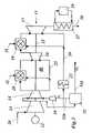
- FIG. 2shows the simplified schematic of an IGCC plant with a gas turbine with reheating or sequential combustion, respectively, as it lends itself to the realization of the invention
- FIG. 3shows an first embodiment example of the return of the nitrogen recovered in the separation of the air to the compressor, in a unit of the type shown in FIG. 2 ;
- FIG. 4shows a second embodiment example of the return of the nitrogen recovered in the separation of the air to the compressor in a unit of the type depicted in FIG. 2 , according to the invention.
- FIG. 2in a markedly simplified schematic, an IGCC plant with a gas turbine with reheating or sequential combustion, respectively, is shown as it lends itself to the realization of the invention.
- the combined cycle power plant 30comprises a gas turbine 11 with a low pressure compressor 13 , a downstream high pressure compressor 14 , a high pressure combustor 18 with a downstream high pressure turbine 16 and a reheat combustor 19 with a downstream low pressure turbine 17 .
- the compressors 13 , 14 and the turbines 16 , 17sit on a commonly shared shaft 15 , by means of which a generator 12 is driven.
- the combustors 18 and 19are supplied with syngas as fuel, which is generated by the gasification of coal (coal feeding 33 ) in a coal gasifier 34 .
- the coal gasifier 34is topped by a cooling device 35 for the syngas, a filtering device 36 and a CO 2 separator 37 with a CO 2 outlet 38 for giving off the separated CO 2 .
- Oxygen (O2)which is recovered in an air separation unit 32 , and introduced via an oxygen line 32 a , is used to gasify the coal in the coal gasifier 34 .
- the air separation unit 32receives compressed air from the outlet of the low pressure compressor 13 .
- the nitrogen (N 2 ), which also occurs in the separation,is led, for example, to the low pressure combustor 19 via nitrogen line 32 b.
- compressed cooling airis tapped off at the outlets of the two compressors 13 and 14 , cooled off in a topped OTC cooler 23 or 24 and then led to the points to be cooled via the corresponding cooling lines 25 and 26 .
- a heat recovery steam generator 27is provided, which, together with a steam turbine 29 that is connected, is part of a water-steam circuit.
- the flue gas that emerges from the heat recovery steam generator 27is released to the outside via a flue gas line 28 .
- the nitrogen coming out of the air separator 32is fed into the low pressure compressor 13 via the nitrogen line 32 b , either in an intermediate stage (continuous line in FIG. 4 ), or directly at the entrance of the low pressure compressor (line of dashes in FIG. 4 ). Pre-compression is not necessary in these cases.
- principles of the present inventioninclude:
- the cool nitrogencools the compressor air, thus representing a kind of “intermediate compressor cooling,” with which all the known advantages of intermediate cooling are associated.
Landscapes
- Engineering & Computer Science (AREA)
- Chemical & Material Sciences (AREA)
- Combustion & Propulsion (AREA)
- Mechanical Engineering (AREA)
- General Engineering & Computer Science (AREA)
- Chemical Kinetics & Catalysis (AREA)
- General Chemical & Material Sciences (AREA)
- Engine Equipment That Uses Special Cycles (AREA)
Abstract
Description
- even in the case of the compressor, there is a significant diversion of compressor air at intermediate compressor pressures,
- the concept of sequential combustion renders an increased stability of combustion possible in conjunction with reduced levels of excess oxygen, and
- a secondary air system is present, which renders it possible to divert air from the compressor, to cool it down, and to use the cooled air for cooling the combustor and the turbine.
- At an intermediate level of pressure (ca. 11-20 bar), air is diverted at the compressor and led to an air separation unit.
- The nitrogen that occurs in the separation of the air, which exhibits a comparatively low temperature, is led back to the compressor, either
- to the input of the compressor or
- to an intermediate stage that is lower than the intermediate stage at which the air was diverted, or
- to exactly the intermediate stage at which the air was also diverted.
- 10,30,40 combined cycle power plant
- 11 gas turbine
- 12 generator
- 13 low pressure compressor
- 14 high pressure compressor
- 15 shaft (gas turbine)
- 16 high pressure turbine
- 17 low pressure turbine
- 18 high pressure combustor
- 19 reheat combustor
- 20 air inlet
- 21,22 fuel feedline
- 23,24 OTC cooler
- 25,26 cooling line
- 27 heat recovery steam generator
- 28 flue gas line
- 29 steam turbine (steam cycle)
- 31 syngas feed line
- 32 air separation unit
- 32aoxygen line
- 32bnitrogen line
- 33 coal feeding
- 34 coal gasifier
- 35 cooling device
- 36 filtering device
- 37 CO2separator
- 38 CO2outlet
- 39 compressor
Claims (7)
Priority Applications (1)
| Application Number | Priority Date | Filing Date | Title |
|---|---|---|---|
| US11/275,479US7584599B2 (en) | 2005-08-10 | 2006-01-09 | Method for operating a gas turbine as well as a gas turbine for implementing the method |
Applications Claiming Priority (2)
| Application Number | Priority Date | Filing Date | Title |
|---|---|---|---|
| US70677605P | 2005-08-10 | 2005-08-10 | |
| US11/275,479US7584599B2 (en) | 2005-08-10 | 2006-01-09 | Method for operating a gas turbine as well as a gas turbine for implementing the method |
Publications (2)
| Publication Number | Publication Date |
|---|---|
| US20070033943A1 US20070033943A1 (en) | 2007-02-15 |
| US7584599B2true US7584599B2 (en) | 2009-09-08 |
Family
ID=39921148
Family Applications (1)
| Application Number | Title | Priority Date | Filing Date |
|---|---|---|---|
| US11/275,479Expired - Fee RelatedUS7584599B2 (en) | 2005-08-10 | 2006-01-09 | Method for operating a gas turbine as well as a gas turbine for implementing the method |
Country Status (2)
| Country | Link |
|---|---|
| US (1) | US7584599B2 (en) |
| CN (1) | CN101238342B (en) |
Cited By (6)
| Publication number | Priority date | Publication date | Assignee | Title |
|---|---|---|---|---|
| US20090044539A1 (en)* | 2006-03-31 | 2009-02-19 | Alstom Technology Ltd. | Fuel lance for a gas turbine installation and a method for operating a fuel lance |
| US20090094960A1 (en)* | 2006-06-07 | 2009-04-16 | Adnan Eroglu | Method for operating a gas turbine, method of operation of a combined cycle power plant, and combined cycle power plant |
| US20100146929A1 (en)* | 2005-08-05 | 2010-06-17 | Guenster Werner | Method for Increasing the Efficiency of a Combined Gas/Steam Power Station With Integrated Gasification Combined Cycle |
| US7898101B1 (en)* | 2006-12-01 | 2011-03-01 | Florida Turbine Technologies, Inc. | Gas turbine engine with synthetic gas fuel |
| US20110173989A1 (en)* | 2010-01-19 | 2011-07-21 | Lennard Helmers | Combined cycle power plant with split compressor |
| US20130269358A1 (en)* | 2012-04-12 | 2013-10-17 | General Electric Company | Methods, systems and apparatus relating to reheat combustion turbine engines with exhaust gas recirculation |
Families Citing this family (9)
| Publication number | Priority date | Publication date | Assignee | Title |
|---|---|---|---|---|
| FR2858398B1 (en)* | 2003-07-30 | 2005-12-02 | Air Liquide | METHOD AND INSTALLATION FOR SUPPLYING AN AIR SEPARATION UNIT USING A GAS TURBINE |
| US20060228294A1 (en)* | 2005-04-12 | 2006-10-12 | Davis William H | Process and apparatus using a molten metal bath |
| US7574855B2 (en)* | 2005-08-10 | 2009-08-18 | Alstom Technology Ltd. | Method for operating a gas turbine and a gas turbine for implementing the method |
| US7584598B2 (en)* | 2005-08-10 | 2009-09-08 | Alstom Technology Ltd. | Method for operating a gas turbine and a gas turbine for implementing the method |
| US7513118B2 (en)* | 2005-08-10 | 2009-04-07 | Alstom Technology Ltd. | Method for operating a gas turbine and a gas turbine for implementing the method |
| US7451591B2 (en)* | 2006-05-08 | 2008-11-18 | Econo-Power International Corporation | Production enhancements on integrated gasification combined cycle power plants |
| US8186177B2 (en)* | 2009-01-06 | 2012-05-29 | General Electric Company | Systems for reducing cooling water and power consumption in gasification systems and methods of assembling such systems |
| CN103133173A (en)* | 2011-12-01 | 2013-06-05 | 摩尔动力(北京)技术股份有限公司 | Entropy circulating engine |
| CN109854382A (en)* | 2019-03-13 | 2019-06-07 | 上海发电设备成套设计研究院有限责任公司 | Zero carbon emission heat power generating system of one kind and method |
Citations (29)
| Publication number | Priority date | Publication date | Assignee | Title |
|---|---|---|---|---|
| US1589704A (en) | 1924-09-15 | 1926-06-22 | James A Kenworthy | Oil burner |
| DE947843C (en) | 1954-09-11 | 1956-08-23 | Henschel & Sohn G M B H | Method for using the lock gas produced by pressurized gasifiers in gas turbine operation |
| DE2503193A1 (en) | 1975-01-27 | 1976-07-29 | Linde Ag | PROCESS FOR PRODUCING A HEATING GAS BY PRESSURE GASIFICATION OF CARBON FUELS |
| US4261167A (en) | 1979-04-27 | 1981-04-14 | Texaco Inc. | Process for the generation of power from solid carbonaceous fuels |
| US4488398A (en) | 1981-11-09 | 1984-12-18 | Hitachi, Ltd. | Power plant integrated with coal gasification |
| US4785621A (en) | 1987-05-28 | 1988-11-22 | General Electric Company | Air bottoming cycle for coal gasification plant |
| US4785622A (en) | 1984-12-03 | 1988-11-22 | General Electric Company | Integrated coal gasification plant and combined cycle system with air bleed and steam injection |
| US4896499A (en)* | 1978-10-26 | 1990-01-30 | Rice Ivan G | Compression intercooled gas turbine combined cycle |
| US4986499A (en) | 1989-09-05 | 1991-01-22 | Ponticelli Robert J | Radio installation kit with convertible front panel |
| US5081845A (en)* | 1990-07-02 | 1992-01-21 | Air Products And Chemicals, Inc. | Integrated air separation plant - integrated gasification combined cycle power generator |
| EP0622535A1 (en) | 1993-04-27 | 1994-11-02 | Air Products And Chemicals, Inc. | Use of nitrogen from an air separation unit as gas turbine air compressor feed refrigerant to improve power output |
| EP0634562A2 (en) | 1993-07-16 | 1995-01-18 | Air Products And Chemicals, Inc. | Integrated air separation - gas turbine power generation process |
| US5459994A (en)* | 1993-05-28 | 1995-10-24 | Praxair Technology, Inc. | Gas turbine-air separation plant combination |
| JPH08218891A (en) | 1995-02-09 | 1996-08-27 | Hitachi Ltd | Gasification power plant |
| US5577378A (en) | 1993-04-08 | 1996-11-26 | Abb Management Ag | Gas turbine group with reheat combustor |
| EP0773416A2 (en) | 1995-11-07 | 1997-05-14 | Air Products And Chemicals, Inc. | Operation of integrated gasification combined cycle power generation systems at part load |
| EP0795685A1 (en) | 1996-03-14 | 1997-09-17 | Asea Brown Boveri Ag | Multi-staged gas-turbine with steam cooling and feeding into the combustor |
| JPH1130131A (en) | 1997-07-09 | 1999-02-02 | Hitachi Ltd | Gasification combined cycle power plant and operation method thereof |
| GB2335953A (en) | 1998-03-30 | 1999-10-06 | Magnox Electric Plc | Air extraction from a power generation turbine |
| US6116016A (en) | 1996-09-09 | 2000-09-12 | Kabushiki Kaisha Toshiba | Gas turbine apparatus using fuel containing vanadium |
| EP1098077A2 (en) | 1999-11-03 | 2001-05-09 | ALSTOM POWER (Schweiz) AG | Operating method for a power plant |
| US20020077512A1 (en)* | 2000-12-20 | 2002-06-20 | Tendick Rex Carl | Hydrocarbon conversion system and method with a plurality of sources of compressed oxygen-containing gas |
| US20020148213A1 (en) | 2001-03-12 | 2002-10-17 | Hong Yu | Re-fired gas turbine engine |
| US6487863B1 (en) | 2001-03-30 | 2002-12-03 | Siemens Westinghouse Power Corporation | Method and apparatus for cooling high temperature components in a gas turbine |
| US6513317B2 (en) | 2001-01-11 | 2003-02-04 | General Electric Company | Apparatus for controlling nitrogen injection into gas turbine |
| US20040168468A1 (en) | 2001-06-08 | 2004-09-02 | Jean-Marc Peyron | Method and installation for energy production by means of a gas turbine associated with an air separation unit |
| US20070033942A1 (en) | 2005-08-10 | 2007-02-15 | Eribert Benz | Method for operating a gas turbine and a gas turbine for implementing the method |
| US20070033918A1 (en) | 2005-08-10 | 2007-02-15 | Eribert Benz | Method for operating a gas turbine and a gas turbine for implementing the method |
| US20070039468A1 (en) | 2005-08-10 | 2007-02-22 | Eribert Benz | Method for operating a gas turbine and a gas turbine for implementing the method |
Family Cites Families (3)
| Publication number | Priority date | Publication date | Assignee | Title |
|---|---|---|---|---|
| JPH01275325A (en)* | 1988-04-28 | 1989-11-06 | Tsubakimoto Chain Co | Article classifying conveyer apparatus |
| KR100701718B1 (en)* | 1999-09-14 | 2007-03-29 | 동경 엘렉트론 주식회사 | Substrate Processing Method |
| KR100840751B1 (en)* | 2005-07-26 | 2008-06-24 | 주식회사 실트론 | High quality silicon single crystal ingot manufacturing method, growth apparatus and ingot, wafer made therefrom |
- 2006
- 2006-01-09USUS11/275,479patent/US7584599B2/ennot_activeExpired - Fee Related
- 2006-08-07CNCN200680028980.XApatent/CN101238342B/ennot_activeExpired - Fee Related
Patent Citations (30)
| Publication number | Priority date | Publication date | Assignee | Title |
|---|---|---|---|---|
| US1589704A (en) | 1924-09-15 | 1926-06-22 | James A Kenworthy | Oil burner |
| DE947843C (en) | 1954-09-11 | 1956-08-23 | Henschel & Sohn G M B H | Method for using the lock gas produced by pressurized gasifiers in gas turbine operation |
| DE2503193A1 (en) | 1975-01-27 | 1976-07-29 | Linde Ag | PROCESS FOR PRODUCING A HEATING GAS BY PRESSURE GASIFICATION OF CARBON FUELS |
| US4896499A (en)* | 1978-10-26 | 1990-01-30 | Rice Ivan G | Compression intercooled gas turbine combined cycle |
| US4896499B1 (en)* | 1978-10-26 | 1992-09-15 | G Rice Ivan | |
| US4261167A (en) | 1979-04-27 | 1981-04-14 | Texaco Inc. | Process for the generation of power from solid carbonaceous fuels |
| US4488398A (en) | 1981-11-09 | 1984-12-18 | Hitachi, Ltd. | Power plant integrated with coal gasification |
| US4785622A (en) | 1984-12-03 | 1988-11-22 | General Electric Company | Integrated coal gasification plant and combined cycle system with air bleed and steam injection |
| US4785621A (en) | 1987-05-28 | 1988-11-22 | General Electric Company | Air bottoming cycle for coal gasification plant |
| US4986499A (en) | 1989-09-05 | 1991-01-22 | Ponticelli Robert J | Radio installation kit with convertible front panel |
| US5081845A (en)* | 1990-07-02 | 1992-01-21 | Air Products And Chemicals, Inc. | Integrated air separation plant - integrated gasification combined cycle power generator |
| US5577378A (en) | 1993-04-08 | 1996-11-26 | Abb Management Ag | Gas turbine group with reheat combustor |
| EP0622535A1 (en) | 1993-04-27 | 1994-11-02 | Air Products And Chemicals, Inc. | Use of nitrogen from an air separation unit as gas turbine air compressor feed refrigerant to improve power output |
| US5459994A (en)* | 1993-05-28 | 1995-10-24 | Praxair Technology, Inc. | Gas turbine-air separation plant combination |
| EP0634562A2 (en) | 1993-07-16 | 1995-01-18 | Air Products And Chemicals, Inc. | Integrated air separation - gas turbine power generation process |
| JPH08218891A (en) | 1995-02-09 | 1996-08-27 | Hitachi Ltd | Gasification power plant |
| EP0773416A2 (en) | 1995-11-07 | 1997-05-14 | Air Products And Chemicals, Inc. | Operation of integrated gasification combined cycle power generation systems at part load |
| EP0795685A1 (en) | 1996-03-14 | 1997-09-17 | Asea Brown Boveri Ag | Multi-staged gas-turbine with steam cooling and feeding into the combustor |
| US6116016A (en) | 1996-09-09 | 2000-09-12 | Kabushiki Kaisha Toshiba | Gas turbine apparatus using fuel containing vanadium |
| JPH1130131A (en) | 1997-07-09 | 1999-02-02 | Hitachi Ltd | Gasification combined cycle power plant and operation method thereof |
| GB2335953A (en) | 1998-03-30 | 1999-10-06 | Magnox Electric Plc | Air extraction from a power generation turbine |
| EP1098077A2 (en) | 1999-11-03 | 2001-05-09 | ALSTOM POWER (Schweiz) AG | Operating method for a power plant |
| US20020077512A1 (en)* | 2000-12-20 | 2002-06-20 | Tendick Rex Carl | Hydrocarbon conversion system and method with a plurality of sources of compressed oxygen-containing gas |
| US6513317B2 (en) | 2001-01-11 | 2003-02-04 | General Electric Company | Apparatus for controlling nitrogen injection into gas turbine |
| US20020148213A1 (en) | 2001-03-12 | 2002-10-17 | Hong Yu | Re-fired gas turbine engine |
| US6487863B1 (en) | 2001-03-30 | 2002-12-03 | Siemens Westinghouse Power Corporation | Method and apparatus for cooling high temperature components in a gas turbine |
| US20040168468A1 (en) | 2001-06-08 | 2004-09-02 | Jean-Marc Peyron | Method and installation for energy production by means of a gas turbine associated with an air separation unit |
| US20070033942A1 (en) | 2005-08-10 | 2007-02-15 | Eribert Benz | Method for operating a gas turbine and a gas turbine for implementing the method |
| US20070033918A1 (en) | 2005-08-10 | 2007-02-15 | Eribert Benz | Method for operating a gas turbine and a gas turbine for implementing the method |
| US20070039468A1 (en) | 2005-08-10 | 2007-02-22 | Eribert Benz | Method for operating a gas turbine and a gas turbine for implementing the method |
Non-Patent Citations (9)
| Title |
|---|
| International Search Report for PCT Patent App. No. PCT/EP2006/065105 (Nov. 13, 2006). |
| Mukherjee, D., "State-of-the-art gas turbines-a brief update," ABB Review 1997:4-14;vol. 2; ABB Asea Brown Boveri Ltd., Zurich, Switzerland. |
| Non-Final Office Action issued in U.S. Appl. No. 11/275, 480 (May 13, 2008). |
| Non-Final Office Action issued in U.S. Appl. No. 11/275,477 (Oct. 16, 2008). |
| Non-Final Office Action issued in U.S. Appl. No. 11/275,478 (Oct. 17, 2008). |
| Pending Claims from U.S. Appl. No. 11/275,477 as of Oct. 30, 2008, pp. 1-4. |
| Pending Claims from U.S. Appl. No. 11/275,478 as of Oct. 30, 2008, pp. 1-3. |
| Pending Claims from U.S. Appl. No. 11/275,480 as of Oct. 30, 2008, pp. 1-3. |
| Search Report for Swiss Patent App. No. CH 20222005 (Apr. 5, 2005). |
Cited By (10)
| Publication number | Priority date | Publication date | Assignee | Title |
|---|---|---|---|---|
| US20100146929A1 (en)* | 2005-08-05 | 2010-06-17 | Guenster Werner | Method for Increasing the Efficiency of a Combined Gas/Steam Power Station With Integrated Gasification Combined Cycle |
| US8020388B2 (en)* | 2005-08-05 | 2011-09-20 | Siemens Aktiengesellschaft | Method for increasing the efficiency of a combined gas/steam power station with integrated gasification combined cycle |
| US20090044539A1 (en)* | 2006-03-31 | 2009-02-19 | Alstom Technology Ltd. | Fuel lance for a gas turbine installation and a method for operating a fuel lance |
| US7934381B2 (en)* | 2006-03-31 | 2011-05-03 | Alstom Technology Ltd. | Fuel lance for a gas turbine installation and a method for operating a fuel lance |
| US20090094960A1 (en)* | 2006-06-07 | 2009-04-16 | Adnan Eroglu | Method for operating a gas turbine, method of operation of a combined cycle power plant, and combined cycle power plant |
| US7908842B2 (en)* | 2006-06-07 | 2011-03-22 | Alstom Technology Ltd. | Method for operating a gas turbine, method of operation of a combined cycle power plant, and combined cycle power plant |
| US7898101B1 (en)* | 2006-12-01 | 2011-03-01 | Florida Turbine Technologies, Inc. | Gas turbine engine with synthetic gas fuel |
| US20110173989A1 (en)* | 2010-01-19 | 2011-07-21 | Lennard Helmers | Combined cycle power plant with split compressor |
| US8863492B2 (en) | 2010-01-19 | 2014-10-21 | Siemens Energy, Inc. | Combined cycle power plant with split compressor |
| US20130269358A1 (en)* | 2012-04-12 | 2013-10-17 | General Electric Company | Methods, systems and apparatus relating to reheat combustion turbine engines with exhaust gas recirculation |
Also Published As
| Publication number | Publication date |
|---|---|
| US20070033943A1 (en) | 2007-02-15 |
| CN101238342B (en) | 2012-07-04 |
| CN101238342A (en) | 2008-08-06 |
Similar Documents
| Publication | Publication Date | Title |
|---|---|---|
| US7584599B2 (en) | Method for operating a gas turbine as well as a gas turbine for implementing the method | |
| US7584598B2 (en) | Method for operating a gas turbine and a gas turbine for implementing the method | |
| US7574855B2 (en) | Method for operating a gas turbine and a gas turbine for implementing the method | |
| JP5415276B2 (en) | How to operate a gas turbine | |
| US6824575B1 (en) | Integrated coal gasification combined cycle power generator | |
| US20040011057A1 (en) | Ultra-low emission power plant | |
| US6499302B1 (en) | Method and apparatus for fuel gas heating in combined cycle power plants | |
| US6276123B1 (en) | Two stage expansion and single stage combustion power plant | |
| US4785621A (en) | Air bottoming cycle for coal gasification plant | |
| US7513118B2 (en) | Method for operating a gas turbine and a gas turbine for implementing the method | |
| AU2016202047B2 (en) | Method and system for use with an integrated gasification combined cycle plant | |
| CA2618030C (en) | A method for operating a gas turbine and a gas turbine for implementing the method | |
| US9074491B2 (en) | Steam cycle system with thermoelectric generator | |
| CA2618016C (en) | A method for operating a gas turbine as well as a gas turbine for implementing the method | |
| CA2618007C (en) | A method for operating a gas turbine and a gas turbine for implementing the method | |
| CA2617986C (en) | Method for operating a gas turbine and a gas turbine for implementing the method | |
| CA2285286C (en) | Gas turbine for combined cycle power plant | |
| JPH10339109A (en) | Multi-shaft combined cycle power generation plant | |
| US6047549A (en) | Power plant facility | |
| Mondal et al. | Thermal performance of an indirectly heated biogasification based combined cycle plant employing reciprocating compressor | |
| KR100355309B1 (en) | Integration Gasification Combined Cycle system using excess nitrogen from Air Separation Unit | |
| Gambini et al. | Overall Performance of Advanced H2/Air Cycle Power Plants Based on Coal Decarbonisation | |
| JPH11315704A (en) | Combined cycle power plant | |
| JPH1037710A (en) | Combined cycle power plant |
Legal Events
| Date | Code | Title | Description |
|---|---|---|---|
| AS | Assignment | Owner name:ALSTOM TECHNOLOGY LTD, SWITZERLAND Free format text:ASSIGNMENT OF ASSIGNORS INTEREST;ASSIGNORS:BENZ, ERIBERT;WIRSUM, MANFRED;REEL/FRAME:017362/0096;SIGNING DATES FROM 20060124 TO 20060209 | |
| STCF | Information on status: patent grant | Free format text:PATENTED CASE | |
| FPAY | Fee payment | Year of fee payment:4 | |
| AS | Assignment | Owner name:GENERAL ELECTRIC TECHNOLOGY GMBH, SWITZERLAND Free format text:CHANGE OF NAME;ASSIGNOR:ALSTOM TECHNOLOGY LTD;REEL/FRAME:038216/0193 Effective date:20151102 | |
| AS | Assignment | Owner name:ANSALDO ENERGIA IP UK LIMITED, GREAT BRITAIN Free format text:ASSIGNMENT OF ASSIGNORS INTEREST;ASSIGNOR:GENERAL ELECTRIC TECHNOLOGY GMBH;REEL/FRAME:041731/0626 Effective date:20170109 | |
| FPAY | Fee payment | Year of fee payment:8 | |
| FEPP | Fee payment procedure | Free format text:MAINTENANCE FEE REMINDER MAILED (ORIGINAL EVENT CODE: REM.); ENTITY STATUS OF PATENT OWNER: LARGE ENTITY | |
| LAPS | Lapse for failure to pay maintenance fees | Free format text:PATENT EXPIRED FOR FAILURE TO PAY MAINTENANCE FEES (ORIGINAL EVENT CODE: EXP.); ENTITY STATUS OF PATENT OWNER: LARGE ENTITY | |
| STCH | Information on status: patent discontinuation | Free format text:PATENT EXPIRED DUE TO NONPAYMENT OF MAINTENANCE FEES UNDER 37 CFR 1.362 | |
| FP | Lapsed due to failure to pay maintenance fee | Effective date:20210908 |