US7584526B2 - Grip for a motor vehicle - Google Patents
Grip for a motor vehicleDownload PDFInfo
- Publication number
- US7584526B2 US7584526B2US11/449,842US44984206AUS7584526B2US 7584526 B2US7584526 B2US 7584526B2US 44984206 AUS44984206 AUS 44984206AUS 7584526 B2US7584526 B2US 7584526B2
- Authority
- US
- United States
- Prior art keywords
- shells
- holding grip
- connection element
- grip according
- supporting carrier
- Prior art date
- Legal status (The legal status is an assumption and is not a legal conclusion. Google has not performed a legal analysis and makes no representation as to the accuracy of the status listed.)
- Active, expires
Links
Images


Classifications
- B—PERFORMING OPERATIONS; TRANSPORTING
- B60—VEHICLES IN GENERAL
- B60N—SEATS SPECIALLY ADAPTED FOR VEHICLES; VEHICLE PASSENGER ACCOMMODATION NOT OTHERWISE PROVIDED FOR
- B60N3/00—Arrangements or adaptations of other passenger fittings, not otherwise provided for
- B60N3/02—Arrangements or adaptations of other passenger fittings, not otherwise provided for of hand grips or straps
- B60N3/026—Arrangements or adaptations of other passenger fittings, not otherwise provided for of hand grips or straps characterised by the fixing means
Definitions
- the present inventionrelates to a grip for a motor vehicle consisting of two half shells which can be connected with one another and have a supporting carrier situated on the inside, and the holding grip can be connected particularly with a transmission tunnel of the motor vehicle or with a vehicle structure.
- FR 15 62 374discloses a grip in which a reinforcing core is embedded. Furthermore, a grip consisting of two shell bodies is described in DE 76 23 712 U, in which the shell bodies can be assembled and are connected with one another by projections and indentations arranged on the joining surface and mutually engaging in the manner of snap fasteners.
- DE 87 06 310 U1discloses a roof holding grip consisting of two shells which can be assembled, in which case one shell comprises a hook on a connecting edge, which hook can be fitted into a slot at the opposite connecting edge of the other shell.
- An object of the present inventionis to provide a holding grip for a motor vehicle which can easily be produced and assembled, has a stable construction and has fastening possibilities on a vehicle component, for example, on a transmission tunnel of the vehicle body.
- this objectis achieved by providing that a supporting carrier is arranged between the two semicircular grip shells made of plastic, which supporting carrier has an I-shaped profile in its cross-section and, at one free end, has a connection element with fastening bores which projects from the grip shells and, at its other end facing away from this connection element, has a sleeve-type other connection element which is arranged inside the grip shell and has a threaded bore for a screwing device for a fastening to the vehicle structure.
- an inserted metallic core or a core consisting of a plastic materialforms a supporting carrier which provides the grip with an optimal stability, prevents a bending due to a load and can be fastened in a simple manner.
- thisis essentially achieved in that a, for example, metallic supporting carrier is arranged between the two semicircular grip shells made of plastic.
- this supporting carrierconsists of an I-section and is provided with a connection element of an angular cross-section which projects out of the grip shells and has fastening bores.
- a sleeve-type other connection elementis provided which is molded on, is arranged inside the grip shells and is provided with a threaded bore for a screwing device for a fastening to the vehicle.
- the supporting carrierconsisting of an I-section points with its flanges to the connecting edges of the grip shells, and a web of the I-section extends in a common plane with the connecting edges, and the interior surfaces of the grip shells are supported on the front edges of the flanges.
- this arrangementsimplifies the assembly of the two grip shells and, on the other hand, the continuous supporting carrier with end-side fastening possibilities permits a stable linkage to the vehicle structure; in this particular case, to a transmission tunnel of the vehicle.
- one grip shellhas at least one centering bush on the interior surface of one grip shell with a centering pin of the other grip shell being fitted into the centering bush for aligning the two grip shells with respect to one another.
- connection of the holding griptakes place such that the sleeve-type connection element of the supporting carrier is arranged to fill out the space between the two grip shells, and an insertion piece with a threaded bore is held between webs of the connection element.
- the projecting connection element of the supporting carrierhas at least one continuous bore for a fastening screw which extends transversely to the grip in the installed position, and the connection element as well as screws are covered by way of a cap adjoining the grip shell.
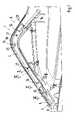
- FIG. 1is a view of a grip shell with an inserted supporting carrier
- FIG. 2is a sectional view along line II-II of FIG. 1 of the holding grip in the area of a centering pin;
- FIG. 3is a sectional view along line III-III of FIG. 1 of the holding grip in the area of an end-side connection element;
- FIG. 4is a sectional view along line IV-IV of FIG. 1 of the grip shell and the supporting carrier;
- FIG. 5is a sectional view along line V-V of FIG. 1 of the holding grip in the area of a hot connection point of the supporting carrier;
- FIG. 6is a sectional view along line VI-VI of FIG. 1 of the holding grip in the area of an end-side connection of the supporting carrier with the vehicle;
- FIG. 7is an enlarged representation of the connecting edges of the grip shells with indentations.
- the holding grip 1comprises two semicircular grip shells 2 , 3 mutually connected, for example, by a gluing-together or locking-together.
- a supporting carrier 4which in its cross-section consists of an I-profile, is arranged in an embedded manner inside these grip shells 2 , 3 and which in each case has connection elements 5 , 6 on the end side for a fastening to the vehicle structure.
- connection elements 5 , 6are constructed in one piece with the supporting carrier 4 .
- Connection element 5extends out of the grip shells 2 , 3 in a bare manner or exposed and is covered by a shell 8 .
- This connection element 5has, for example, a square cross-section and has at least two transversely extending bores 9 , 10 which extend to the grip 1 and accommodate the fastening screws 11 which can be connected with the vehicle structure 12 .
- the additional connection element 6consists of a sleeve-shaped receiving element 13 which is arranged to be embedded in the two grip shells 2 , 3 .
- a receiving bore 14 ( FIG. 3 ) for a fastening screw ( 15 )is arranged which establishes a fixed connection to the vehicle structure.
- the profile of the supporting carrier 4is situated with its web 15 in a common plane X-X with abutting connection edges 16 , 16 a .
- the grip shells 2 , 3are supported on front edges of the flanges 18 , 19 of the profile.
- the connecting edges 16 , 16 a and 17 , 17 a of the grip shells 2 , 3are arranged to be mutually overlapping.
- the connecting edges 16 a , 17 a of grip shell 16have a shoulder 20 , 21 into which the opposite connecting edges 16 , 17 are inserted.
- one indentation 22 , 23respectively is formed in the connection area of the edges 16 , 16 a and 17 , 17 a , and a seam of a covering made of leather or another material for the grip 1 is situated in the indentation 22 , 23 .
- the other materialmay be a fabric, a foil, a leather imitation or the like.
- the supporting carrier 4can be fixed on a grip shell 2 , 3 by a welding dome 24 ( FIG. 5 ) which is hot-riveted for this purpose.
- the welding dome 24comprises, for example, two spaced ribs 25 and 26 .
- centering pins 27( FIG. 2 ) with a cross-shaped cross-section are provided on one grip shell 2 or 3 and can each be fitted into a centering bush 28 to hold the two grip shells 2 , 3 in a predetermined connection position with respect to one another.
- the grip shells 2 , 3can be provided with a covering of leather or another covering.
Landscapes
- Engineering & Computer Science (AREA)
- Transportation (AREA)
- Mechanical Engineering (AREA)
- Passenger Equipment (AREA)
Abstract
Description
Claims (16)
Applications Claiming Priority (2)
| Application Number | Priority Date | Filing Date | Title |
|---|---|---|---|
| DE102005026836ADE102005026836A1 (en) | 2005-06-10 | 2005-06-10 | Handle for a motor vehicle |
| DE102005026836.6 | 2005-06-10 |
Publications (2)
| Publication Number | Publication Date |
|---|---|
| US20070018471A1 US20070018471A1 (en) | 2007-01-25 |
| US7584526B2true US7584526B2 (en) | 2009-09-08 |
Family
ID=37012028
Family Applications (1)
| Application Number | Title | Priority Date | Filing Date |
|---|---|---|---|
| US11/449,842Active2027-11-30US7584526B2 (en) | 2005-06-10 | 2006-06-09 | Grip for a motor vehicle |
Country Status (3)
| Country | Link |
|---|---|
| US (1) | US7584526B2 (en) |
| EP (1) | EP1731360B8 (en) |
| DE (2) | DE102005026836A1 (en) |
Cited By (1)
| Publication number | Priority date | Publication date | Assignee | Title |
|---|---|---|---|---|
| US20190111821A1 (en)* | 2016-03-28 | 2019-04-18 | Nifco America Corp. | Assist grip |
Families Citing this family (4)
| Publication number | Priority date | Publication date | Assignee | Title |
|---|---|---|---|---|
| US8905168B2 (en)* | 2011-10-06 | 2014-12-09 | Kawasaki Jukogyo Kabushiki Kaisha | Utility vehicle |
| US9162354B1 (en)* | 2014-03-26 | 2015-10-20 | Green Guard Industry Ltd. | Handle cover structure |
| US10166158B2 (en)* | 2015-07-17 | 2019-01-01 | Eos Surfaces, Llc | Antimicrobial covers for rails |
| DE102015215780A1 (en)* | 2015-08-19 | 2017-02-23 | Siemens Aktiengesellschaft | Haptic handrail cover |
Citations (22)
| Publication number | Priority date | Publication date | Assignee | Title |
|---|---|---|---|---|
| US2146415A (en)* | 1937-06-10 | 1939-02-07 | Aluminum Cooking Utensil Compa | Two-piece bakelite grip |
| US2231222A (en)* | 1939-06-26 | 1941-02-11 | Kewaskum Aluminum Company | Handle for cooking utensils |
| FR1225785A (en) | 1959-02-18 | 1960-07-04 | Maglum | Metal handle, in particular for motor vehicle door |
| FR1562374A (en) | 1967-08-19 | 1969-04-04 | ||
| US3977054A (en) | 1975-01-06 | 1976-08-31 | Chivas Products Ltd. | Strap fitting for automobile interior and other uses |
| DE7623712U1 (en) | 1976-07-28 | 1976-11-18 | Messerschmitt-Boelkow-Blohm Gmbh, 8000 Muenchen | HANDLE |
| DE7713094U1 (en) | 1977-04-26 | 1977-09-01 | Gebr. Happich Gmbh, 5600 Wuppertal | HANDLE, IN PARTICULAR HANDLE FOR VEHICLES |
| US4261078A (en)* | 1980-01-21 | 1981-04-14 | Samsonite Corporation | Carrying handle |
| US4340990A (en)* | 1978-12-28 | 1982-07-27 | Societe Delsey | Object intended to be held in the hand, in particular a suitcase handle, and a process for manufacturing same |
| DE8706310U1 (en) | 1987-05-02 | 1987-06-19 | Zipperle, Michael, 7140 Ludwigsburg | Roof grab handle for motor vehicles |
| DE19522224A1 (en) | 1994-06-24 | 1996-08-08 | Happich Gmbh Gebr | Handrail and support holder kit for buses and coaches |
| US5579556A (en)* | 1995-12-14 | 1996-12-03 | Chung; Fu S. | Handle of a stroller |
| US5771536A (en)* | 1995-08-30 | 1998-06-30 | Weber-Stephen Products Co. | Handle assembly for grill |
| US5781956A (en)* | 1996-01-17 | 1998-07-21 | Marshalltown Trowel Company | Plastic molded float handle |
| US5943737A (en)* | 1996-08-07 | 1999-08-31 | Honda Giken Kogyo Kabushiki Kaisha | Door grip structure for vehicles |
| DE29920776U1 (en) | 1999-11-26 | 2000-01-13 | Utescheny-Endos GmbH, 75059 Zaisenhausen | Handle for vehicle interiors |
| US6092858A (en)* | 1995-07-14 | 2000-07-25 | Nylex Corporation Limited | Moulded interior door panel |
| US6247204B1 (en)* | 1999-09-15 | 2001-06-19 | Mike Hamby | Handle for trowel and related tools |
| JP2001219775A (en) | 2000-02-08 | 2001-08-14 | Kasai Kogyo Co Ltd | Fixing structure of hollow interior member |
| US20020108213A1 (en)* | 2000-11-21 | 2002-08-15 | Kraft Tool Company | Soft grip tool handle and method of manufacture |
| DE10204168C2 (en) | 2002-02-01 | 2003-11-27 | Johnson Contr Interiors Gmbh | Interior part for a vehicle |
| US20060064852A1 (en)* | 2004-09-24 | 2006-03-30 | Penn Elcom, Inc. | Strap handle |
- 2005
- 2005-06-10DEDE102005026836Apatent/DE102005026836A1/ennot_activeCeased
- 2006
- 2006-03-14DEDE502006000788Tpatent/DE502006000788D1/enactiveActive
- 2006-03-14EPEP06005139Apatent/EP1731360B8/ennot_activeCeased
- 2006-06-09USUS11/449,842patent/US7584526B2/enactiveActive
Patent Citations (22)
| Publication number | Priority date | Publication date | Assignee | Title |
|---|---|---|---|---|
| US2146415A (en)* | 1937-06-10 | 1939-02-07 | Aluminum Cooking Utensil Compa | Two-piece bakelite grip |
| US2231222A (en)* | 1939-06-26 | 1941-02-11 | Kewaskum Aluminum Company | Handle for cooking utensils |
| FR1225785A (en) | 1959-02-18 | 1960-07-04 | Maglum | Metal handle, in particular for motor vehicle door |
| FR1562374A (en) | 1967-08-19 | 1969-04-04 | ||
| US3977054A (en) | 1975-01-06 | 1976-08-31 | Chivas Products Ltd. | Strap fitting for automobile interior and other uses |
| DE7623712U1 (en) | 1976-07-28 | 1976-11-18 | Messerschmitt-Boelkow-Blohm Gmbh, 8000 Muenchen | HANDLE |
| DE7713094U1 (en) | 1977-04-26 | 1977-09-01 | Gebr. Happich Gmbh, 5600 Wuppertal | HANDLE, IN PARTICULAR HANDLE FOR VEHICLES |
| US4340990A (en)* | 1978-12-28 | 1982-07-27 | Societe Delsey | Object intended to be held in the hand, in particular a suitcase handle, and a process for manufacturing same |
| US4261078A (en)* | 1980-01-21 | 1981-04-14 | Samsonite Corporation | Carrying handle |
| DE8706310U1 (en) | 1987-05-02 | 1987-06-19 | Zipperle, Michael, 7140 Ludwigsburg | Roof grab handle for motor vehicles |
| DE19522224A1 (en) | 1994-06-24 | 1996-08-08 | Happich Gmbh Gebr | Handrail and support holder kit for buses and coaches |
| US6092858A (en)* | 1995-07-14 | 2000-07-25 | Nylex Corporation Limited | Moulded interior door panel |
| US5771536A (en)* | 1995-08-30 | 1998-06-30 | Weber-Stephen Products Co. | Handle assembly for grill |
| US5579556A (en)* | 1995-12-14 | 1996-12-03 | Chung; Fu S. | Handle of a stroller |
| US5781956A (en)* | 1996-01-17 | 1998-07-21 | Marshalltown Trowel Company | Plastic molded float handle |
| US5943737A (en)* | 1996-08-07 | 1999-08-31 | Honda Giken Kogyo Kabushiki Kaisha | Door grip structure for vehicles |
| US6247204B1 (en)* | 1999-09-15 | 2001-06-19 | Mike Hamby | Handle for trowel and related tools |
| DE29920776U1 (en) | 1999-11-26 | 2000-01-13 | Utescheny-Endos GmbH, 75059 Zaisenhausen | Handle for vehicle interiors |
| JP2001219775A (en) | 2000-02-08 | 2001-08-14 | Kasai Kogyo Co Ltd | Fixing structure of hollow interior member |
| US20020108213A1 (en)* | 2000-11-21 | 2002-08-15 | Kraft Tool Company | Soft grip tool handle and method of manufacture |
| DE10204168C2 (en) | 2002-02-01 | 2003-11-27 | Johnson Contr Interiors Gmbh | Interior part for a vehicle |
| US20060064852A1 (en)* | 2004-09-24 | 2006-03-30 | Penn Elcom, Inc. | Strap handle |
Non-Patent Citations (1)
| Title |
|---|
| European Search Report dated Sep. 28, 2006 with English translation of relevant portion (Four (4) Pages). |
Cited By (1)
| Publication number | Priority date | Publication date | Assignee | Title |
|---|---|---|---|---|
| US20190111821A1 (en)* | 2016-03-28 | 2019-04-18 | Nifco America Corp. | Assist grip |
Also Published As
| Publication number | Publication date |
|---|---|
| DE102005026836A1 (en) | 2006-12-21 |
| US20070018471A1 (en) | 2007-01-25 |
| EP1731360B1 (en) | 2008-05-21 |
| EP1731360B8 (en) | 2008-08-13 |
| EP1731360A1 (en) | 2006-12-13 |
| DE502006000788D1 (en) | 2008-07-03 |
Similar Documents
| Publication | Publication Date | Title |
|---|---|---|
| US7584526B2 (en) | Grip for a motor vehicle | |
| US8342477B2 (en) | Hinged clamp bracket | |
| US20180031149A1 (en) | Pipe clamp | |
| AU2014268101B2 (en) | Attachment element | |
| US10919197B2 (en) | Device for reinforcing, sealing or insulating a structural element | |
| CN108883685A (en) | Torsion-bar spring | |
| SE9700485D0 (en) | automotive Body | |
| KR102361302B1 (en) | Under cover fastening clip | |
| JP2006322308A (en) | Sleeper | |
| CZ20001323A3 (en) | Compound structural element | |
| JP2015010664A (en) | Connection part structure between plate members | |
| US20240116450A1 (en) | Roof rack for a motor vehicle, motor vehicle, and method for producing a roof rack | |
| US6872463B2 (en) | Reinforcing rod for body and/or chassis elements for a motor vehicle | |
| KR970038686A (en) | Indoor ceiling structure for bus | |
| KR200147803Y1 (en) | Fastening device of prefabricated panel | |
| CZ264199A3 (en) | Attachment plate to fix the hinges to the retaining wall | |
| JP4021470B1 (en) | Pipe fitting | |
| JP3703896B2 (en) | Joining member | |
| JP2010013013A (en) | Structure of hinge cover section of vehicle and assembling method of structure of hinge cover section of vehicle | |
| KR20180042586A (en) | A greenhouses are equipped with a reinforced structure and method of construction | |
| KR200384756Y1 (en) | Joint ball for connecting beam | |
| CN222558024U (en) | Prefabricated wall panel buckle groove structure | |
| US11293467B2 (en) | Chassis anchoring systems | |
| KR200319043Y1 (en) | Structural expansion joint | |
| KR200257673Y1 (en) | Connecting device of building prefabricated panel |
Legal Events
| Date | Code | Title | Description |
|---|---|---|---|
| AS | Assignment | Owner name:DR. ING. H.C.F. PORSCHE AKTIENGESELLSCHAFT, GERMAN Free format text:ASSIGNMENT OF ASSIGNORS INTEREST;ASSIGNOR:PANDURA, MICHAEL;REEL/FRAME:018443/0676 Effective date:20060814 | |
| AS | Assignment | Owner name:DR. ING. H.C.F. PORSCHE AKTIENGESELLSCHAFT (COMPAN Free format text:MERGER;ASSIGNOR:DR. ING. H.C.F. PORSCHE AKTIENGESELLSCHAFT;REEL/FRAME:021184/0926 Effective date:20070427 | |
| FEPP | Fee payment procedure | Free format text:PAYOR NUMBER ASSIGNED (ORIGINAL EVENT CODE: ASPN); ENTITY STATUS OF PATENT OWNER: LARGE ENTITY | |
| STCF | Information on status: patent grant | Free format text:PATENTED CASE | |
| AS | Assignment | Owner name:DR. ING. H.C.F. PORSCHE AKTIENGESELLSCHAFT, GERMAN Free format text:CHANGE OF NAME;ASSIGNOR:PORSCHE ZWISCHENHOLDING GMBH;REEL/FRAME:025227/0747 Effective date:20091130 Owner name:PORSCHE ZWISCHENHOLDING GMBH, GERMANY Free format text:MERGER;ASSIGNOR:DR. ING. H.C.F. PORSCHE AKTIENGESELLSCHAFT;REEL/FRAME:025227/0699 Effective date:20091125 | |
| FPAY | Fee payment | Year of fee payment:4 | |
| FPAY | Fee payment | Year of fee payment:8 | |
| MAFP | Maintenance fee payment | Free format text:PAYMENT OF MAINTENANCE FEE, 12TH YEAR, LARGE ENTITY (ORIGINAL EVENT CODE: M1553); ENTITY STATUS OF PATENT OWNER: LARGE ENTITY Year of fee payment:12 |