US7584298B2 - Topology aware route control - Google Patents
Topology aware route controlDownload PDFInfo
- Publication number
- US7584298B2 US7584298B2US10/735,589US73558903AUS7584298B2US 7584298 B2US7584298 B2US 7584298B2US 73558903 AUS73558903 AUS 73558903AUS 7584298 B2US7584298 B2US 7584298B2
- Authority
- US
- United States
- Prior art keywords
- data
- path
- network
- paths
- address space
- Prior art date
- Legal status (The legal status is an assumption and is not a legal conclusion. Google has not performed a legal analysis and makes no representation as to the accuracy of the status listed.)
- Active, expires
Links
- 238000005259measurementMethods0.000claimsabstractdescription50
- 238000000034methodMethods0.000claimsdescription163
- 239000000523sampleSubstances0.000claimsdescription156
- 230000000694effectsEffects0.000claimsdescription14
- 238000013439planningMethods0.000claimsdescription3
- 244000025221Humulus lupulusSpecies0.000description122
- 230000008569processEffects0.000description55
- 238000004458analytical methodMethods0.000description47
- 230000002776aggregationEffects0.000description40
- 238000004220aggregationMethods0.000description40
- 238000004891communicationMethods0.000description26
- 235000008694Humulus lupulusNutrition0.000description24
- 230000004044responseEffects0.000description24
- 238000010586diagramMethods0.000description21
- 230000008859changeEffects0.000description20
- 230000009471actionEffects0.000description17
- 238000012544monitoring processMethods0.000description15
- 230000006399behaviorEffects0.000description12
- 239000000047productSubstances0.000description11
- 230000015556catabolic processEffects0.000description10
- 238000013459approachMethods0.000description9
- 230000005540biological transmissionEffects0.000description9
- 239000003795chemical substances by applicationSubstances0.000description9
- 238000006731degradation reactionMethods0.000description9
- 230000006855networkingEffects0.000description9
- 238000003860storageMethods0.000description9
- 238000001514detection methodMethods0.000description8
- 230000006870functionEffects0.000description8
- 235000019580granularityNutrition0.000description8
- 230000002829reductive effectEffects0.000description7
- 238000005070samplingMethods0.000description7
- 238000001914filtrationMethods0.000description6
- 230000007246mechanismEffects0.000description6
- 238000012546transferMethods0.000description6
- 230000008901benefitEffects0.000description5
- 238000009826distributionMethods0.000description5
- 238000005516engineering processMethods0.000description5
- 238000005206flow analysisMethods0.000description5
- 230000003287optical effectEffects0.000description5
- 102100028253Breast cancer anti-estrogen resistance protein 3Human genes0.000description4
- 102100038284Cytospin-BHuman genes0.000description4
- 101710144128Non-structural protein 2Proteins0.000description4
- 101710144121Non-structural protein 5Proteins0.000description4
- 238000012545processingMethods0.000description4
- 101000610620Homo sapiens Putative serine protease 29Proteins0.000description3
- 102100040345Putative serine protease 29Human genes0.000description3
- 230000004931aggregating effectEffects0.000description3
- 239000013256coordination polymerSubstances0.000description3
- 239000004744fabricSubstances0.000description3
- 238000012423maintenanceMethods0.000description3
- 230000008520organizationEffects0.000description3
- 230000002085persistent effectEffects0.000description3
- 230000000246remedial effectEffects0.000description3
- 239000013589supplementSubstances0.000description3
- 238000012384transportation and deliveryMethods0.000description3
- 238000011144upstream manufacturingMethods0.000description3
- 101710128742Cytochrome b6-f complex iron-sulfur subunit 2Proteins0.000description2
- 101150045440ISP1 geneProteins0.000description2
- 101100353471Mus musculus Prss28 geneProteins0.000description2
- 101710138767Non-structural glycoprotein 4Proteins0.000description2
- 101710144127Non-structural protein 1Proteins0.000description2
- 102100031776SH2 domain-containing protein 3AHuman genes0.000description2
- 101100509103Schizosaccharomyces pombe (strain 972 / ATCC 24843) ish1 geneProteins0.000description2
- 101100397225Schizosaccharomyces pombe (strain 972 / ATCC 24843) isp3 geneProteins0.000description2
- 102100031056Serine protease 57Human genes0.000description2
- 101710197596Serine protease 57Proteins0.000description2
- 238000004364calculation methodMethods0.000description2
- 238000006243chemical reactionMethods0.000description2
- 238000007796conventional methodMethods0.000description2
- 238000012937correctionMethods0.000description2
- 230000000593degrading effectEffects0.000description2
- 208000002153familial abdominal 3 aortic aneurysmDiseases0.000description2
- 230000006872improvementEffects0.000description2
- 230000000670limiting effectEffects0.000description2
- 230000007774longtermEffects0.000description2
- 238000007726management methodMethods0.000description2
- 230000002093peripheral effectEffects0.000description2
- 230000009467reductionEffects0.000description2
- 238000010079rubber tappingMethods0.000description2
- 238000013024troubleshootingMethods0.000description2
- 230000000007visual effectEffects0.000description2
- 241001385733Aesculus indicaSpecies0.000description1
- 101000775660Anarhichas lupus Type-3 ice-structuring protein 1.5Proteins0.000description1
- 101000775628Anarhichas lupus Type-3 ice-structuring protein 1.9Proteins0.000description1
- 238000012935AveragingMethods0.000description1
- RYGMFSIKBFXOCR-UHFFFAOYSA-NCopperChemical compound[Cu]RYGMFSIKBFXOCR-UHFFFAOYSA-N0.000description1
- 235000009809Humulus lupulus var lupuloidesNutrition0.000description1
- 235000006878Humulus lupulus var neomexicanusNutrition0.000description1
- 235000009800Humulus lupulus var pubescensNutrition0.000description1
- 235000009808Humulus lupulus var. lupulusNutrition0.000description1
- 101710144111Non-structural protein 3Proteins0.000description1
- 101000643905Nostoc sp. (strain PCC 7120 / SAG 25.82 / UTEX 2576) Cytochrome b6-f complex iron-sulfur subunit 3Proteins0.000description1
- 101000775697Pseudopleuronectes americanus Ice-structuring protein 3Proteins0.000description1
- 102100021798SH2 domain-containing protein 3CHuman genes0.000description1
- ODCKICSDIPVTRM-UHFFFAOYSA-N[4-[2-hydroxy-3-(propan-2-ylazaniumyl)propoxy]naphthalen-1-yl] sulfateChemical compoundC1=CC=C2C(OCC(O)CNC(C)C)=CC=C(OS(O)(=O)=O)C2=C1ODCKICSDIPVTRM-UHFFFAOYSA-N0.000description1
- 230000006978adaptationEffects0.000description1
- 230000002411adverseEffects0.000description1
- 230000004075alterationEffects0.000description1
- 230000002547anomalous effectEffects0.000description1
- 238000013528artificial neural networkMethods0.000description1
- 230000002457bidirectional effectEffects0.000description1
- 238000004422calculation algorithmMethods0.000description1
- 238000012508change requestMethods0.000description1
- 238000004590computer programMethods0.000description1
- 239000000470constituentSubstances0.000description1
- 238000010276constructionMethods0.000description1
- 238000007405data analysisMethods0.000description1
- 230000003247decreasing effectEffects0.000description1
- 230000001934delayEffects0.000description1
- 230000001627detrimental effectEffects0.000description1
- 238000011161developmentMethods0.000description1
- 230000007613environmental effectEffects0.000description1
- 230000007717exclusionEffects0.000description1
- 239000000284extractSubstances0.000description1
- 230000002349favourable effectEffects0.000description1
- 239000000835fiberSubstances0.000description1
- 238000009499grossingMethods0.000description1
- 230000000977initiatory effectEffects0.000description1
- 238000009434installationMethods0.000description1
- 230000003993interactionEffects0.000description1
- 230000002452interceptive effectEffects0.000description1
- 238000013507mappingMethods0.000description1
- 238000000691measurement methodMethods0.000description1
- 239000000203mixtureSubstances0.000description1
- YHXISWVBGDMDLQ-UHFFFAOYSA-NmoclobemideChemical compoundC1=CC(Cl)=CC=C1C(=O)NCCN1CCOCC1YHXISWVBGDMDLQ-UHFFFAOYSA-N0.000description1
- 238000005457optimizationMethods0.000description1
- 230000001151other effectEffects0.000description1
- 230000036961partial effectEffects0.000description1
- 230000007170pathologyEffects0.000description1
- 230000000737periodic effectEffects0.000description1
- 230000000644propagated effectEffects0.000description1
- 230000005855radiationEffects0.000description1
- 230000010076replicationEffects0.000description1
- 230000003362replicative effectEffects0.000description1
- 238000012552reviewMethods0.000description1
- 230000008054signal transmissionEffects0.000description1
- 238000007619statistical methodMethods0.000description1
- 230000008685targetingEffects0.000description1
- 230000002123temporal effectEffects0.000description1
- 230000036962time dependentEffects0.000description1
- 230000007723transport mechanismEffects0.000description1
- 230000001960triggered effectEffects0.000description1
- 239000013598vectorSubstances0.000description1
Images


Classifications
- H—ELECTRICITY
- H04—ELECTRIC COMMUNICATION TECHNIQUE
- H04L—TRANSMISSION OF DIGITAL INFORMATION, e.g. TELEGRAPHIC COMMUNICATION
- H04L45/00—Routing or path finding of packets in data switching networks
- H04L45/24—Multipath
- H—ELECTRICITY
- H04—ELECTRIC COMMUNICATION TECHNIQUE
- H04L—TRANSMISSION OF DIGITAL INFORMATION, e.g. TELEGRAPHIC COMMUNICATION
- H04L43/00—Arrangements for monitoring or testing data switching networks
- H—ELECTRICITY
- H04—ELECTRIC COMMUNICATION TECHNIQUE
- H04L—TRANSMISSION OF DIGITAL INFORMATION, e.g. TELEGRAPHIC COMMUNICATION
- H04L45/00—Routing or path finding of packets in data switching networks
- H04L45/02—Topology update or discovery
- H—ELECTRICITY
- H04—ELECTRIC COMMUNICATION TECHNIQUE
- H04L—TRANSMISSION OF DIGITAL INFORMATION, e.g. TELEGRAPHIC COMMUNICATION
- H04L45/00—Routing or path finding of packets in data switching networks
- H04L45/02—Topology update or discovery
- H04L45/04—Interdomain routing, e.g. hierarchical routing
- H—ELECTRICITY
- H04—ELECTRIC COMMUNICATION TECHNIQUE
- H04L—TRANSMISSION OF DIGITAL INFORMATION, e.g. TELEGRAPHIC COMMUNICATION
- H04L45/00—Routing or path finding of packets in data switching networks
- H04L45/12—Shortest path evaluation
- H04L45/123—Evaluation of link metrics
- H—ELECTRICITY
- H04—ELECTRIC COMMUNICATION TECHNIQUE
- H04L—TRANSMISSION OF DIGITAL INFORMATION, e.g. TELEGRAPHIC COMMUNICATION
- H04L45/00—Routing or path finding of packets in data switching networks
- H04L45/12—Shortest path evaluation
- H04L45/128—Shortest path evaluation for finding disjoint paths
- H04L45/1283—Shortest path evaluation for finding disjoint paths with disjoint links
- H—ELECTRICITY
- H04—ELECTRIC COMMUNICATION TECHNIQUE
- H04L—TRANSMISSION OF DIGITAL INFORMATION, e.g. TELEGRAPHIC COMMUNICATION
- H04L45/00—Routing or path finding of packets in data switching networks
- H04L45/24—Multipath
- H04L45/247—Multipath using M:N active or standby paths
- H—ELECTRICITY
- H04—ELECTRIC COMMUNICATION TECHNIQUE
- H04L—TRANSMISSION OF DIGITAL INFORMATION, e.g. TELEGRAPHIC COMMUNICATION
- H04L45/00—Routing or path finding of packets in data switching networks
- H04L45/302—Route determination based on requested QoS
- H04L45/306—Route determination based on the nature of the carried application
- H04L45/3065—Route determination based on the nature of the carried application for real time traffic
- H—ELECTRICITY
- H04—ELECTRIC COMMUNICATION TECHNIQUE
- H04L—TRANSMISSION OF DIGITAL INFORMATION, e.g. TELEGRAPHIC COMMUNICATION
- H04L45/00—Routing or path finding of packets in data switching networks
- H04L45/38—Flow based routing
- H—ELECTRICITY
- H04—ELECTRIC COMMUNICATION TECHNIQUE
- H04L—TRANSMISSION OF DIGITAL INFORMATION, e.g. TELEGRAPHIC COMMUNICATION
- H04L45/00—Routing or path finding of packets in data switching networks
- H04L45/70—Routing based on monitoring results
- H—ELECTRICITY
- H04—ELECTRIC COMMUNICATION TECHNIQUE
- H04L—TRANSMISSION OF DIGITAL INFORMATION, e.g. TELEGRAPHIC COMMUNICATION
- H04L43/00—Arrangements for monitoring or testing data switching networks
- H04L43/10—Active monitoring, e.g. heartbeat, ping or trace-route
- H—ELECTRICITY
- H04—ELECTRIC COMMUNICATION TECHNIQUE
- H04L—TRANSMISSION OF DIGITAL INFORMATION, e.g. TELEGRAPHIC COMMUNICATION
- H04L43/00—Arrangements for monitoring or testing data switching networks
- H04L43/12—Network monitoring probes
- H—ELECTRICITY
- H04—ELECTRIC COMMUNICATION TECHNIQUE
- H04L—TRANSMISSION OF DIGITAL INFORMATION, e.g. TELEGRAPHIC COMMUNICATION
- H04L45/00—Routing or path finding of packets in data switching networks
- H04L45/02—Topology update or discovery
- H04L45/033—Topology update or discovery by updating distance vector protocols
Definitions
- the present inventionrelates generally to the control of data over network communications systems, and more specifically to topology-based route control of data over communications networks.
- Networksare communications systems that connect nodes or points for the purpose of sharing resources.
- a nodetypically represents a computer or collection of computers or other computing devices. Interchangeably referred to herein as a “point,” a node is typically an endpoint for a particular segment along a network “path” or “route.”
- a routedescribes a path between two nodes which may or may not encompass intermediate nodes, connections, sub-routes and the like between a data source, such as a web-based database, and a destination, such as a customer, partner, or branch website.
- Networkstypically represent a topology of devices and connections such as computers, servers, peripheral equipment, and other computing devices, connected by cables, wires, or other communication media for use in transmitting data and information in the form of electronic signals, for example.
- Networksmay be classified in a number of ways, including nodal and topology. Nodes can be classified as servers, computers, or other types of computing devices and typically include routers, hubs, and switches. Networks can also be classified according to the topology of the network.
- topology-based classificationsnetworks are classified by the configuration of the network equipment and components. Star, bus, ring, and hybrid configurations are representative network configurations well known in the art. Another topology-based classification relates a particular type of network to a number of aggregated devices associated therewith.
- a Local Area Network or LANcan be used over a short-distance, such as within a building or small cluster of buildings.
- computing resourcesare spread over a larger area, such as a city or town, a Metropolitan Area Network or MAN may be used.
- Computers, servers, routers, switches, and hubsare representative of some types of equipment that are networked for the purpose of sharing with other users, regardless of the type of network.
- networks over large geographic areasare generally classified as Wide Area Networks or WANs.
- WANscan also connect LANs or other WANs thus forming larger networks encompassing more users and branch offices.
- CIDRclassless inter-domain routing
- a routing tableis established using a variety of network sizes.
- a networkmay have numerous IP addresses, such as a corporate LAN.
- the network(or a group of such networks) is listed in a routing table as a network prefix.
- a prefixcan be, for example, a 32 bit IP address that has an associated netmask indicating how many of the leading bits are significant.
- routing control productsforce users to make a route control decision that improve some portions of the address space at the expense of possibly degrading other portions of the address space related to a second geographic region.
- conventional productsmay not be aware of an address distribution and users consequently confront control decisions that can introduce larger problems than those resolved by limited route control decisions.
- address allocations in a single aggregated routecan fall into widely different locations.
- one of the address allocationsoccurs in San Jose (12.0.128.0/1) and another in New York (12.0.0.0/1). It is uncommon that a single route decision for the /16 can effectively optimize every address in the block. Users may face performance degradations at some destinations in order to optimize performance at other destinations because conventional routing control products do not adjust for multi-homed network configurations. Alternatively, users may fail to recognize this geographic diversity, not realizing a large-scale route (e.g., a /16 route) may be geographically widespread and thus direct data routing in an inefficient manner. Upon fixing small problems for a particular destination will introduce greater problems for a larger set of destinations.
- the productmay then introduce performance route flapping for a large address block.
- control decisions on routes in a routing tablemove large volumes of traffic between two NSPs.
- the delivery of high volumes of advertisementscan significantly disrupt multi-homed enterprise networks.
- the line of signal transmission from a source to a destinationtraverses a “first mile,” a “middle mile,” and a “last mile,” the latter of which can be located at either end of a data path, typically connecting the switch or central office of a telecommunications service provider such as Pacific Bell to a customer's PBX.
- the “last mile,” a bottleneckhas received attention over the past few years.
- the “last mile”is the connection between end-users and a communications network, such as a connection from a central office to a home subscriber or user.
- Systemssuch as xDSL and cable access using coaxial cable have emerged to dramatically improve last mile performance.
- the “first mile” bottleneckis part of the network where content is hosted on Web servers. First mile access has improved, for example, through the use of more powerful Web servers, higher speed communications channels between servers and storage, and load balancing techniques.
- NSPsNetwork Service Providers
- ISPsInternet Service Providers
- Routes received through peering pointsare defined as a single AS away from a BGP routing perspective. That makes these routes highly preferable by BGP (and by the provider because the connections are cost-free). However, when there are capacity problems at a peering point and performance through it suffers, traffic associated with BGP still passes through the problematic peering point and thus, the end-to-end performance and routing of all data traffic will suffer.
- This technologycharacterizes candidate paths in which to route data over and includes at least two types.
- Active probesare the first type, which are near real-time active calibration of the data path, using tools such as ICMP, traceroute, Sting, and vendors or service providers such as CQOS, Inc., and Keynote, Inc.
- Another traditional approachis real time passive analysis of the traffic being sent and received, utilizing such tools as TCPdump, and vendors such as Network Associates, Inc., Narus, Inc., Brix, Inc., and P-cube, Inc.
- an advertisement or announcement for a shorter prefix lengthwill direct data traffic to an increased number of multiple nodes or points, as opposed to the use of a longer prefix length that directs data traffic to specific points.
- the more susceptible a shorter prefixis to geographically-related problems.
- using arbitrarily long prefix lengths such as /24can result in many specific advertisements to numerous specific destinations to solve a single problem.
- inefficient data routing and controlcan lead to significant expenses as high rates and volume of data are often metered on a per unit basis.
- a company using an internet or network service provider that enables access for data traffic over telecommunications networksmay assess charges based upon data throughput, data volume, or time-connection charges. Greater data traffic and usage will result in higher costs charged to the organization providing the data.
- costsmay become too expensive to efficiently use active probes without significantly increasing data volume.
- time and network condition-sensitive applicationsare used among distributed and/or multi-homed enterprises, then inefficient route control will result in significant costs and lowered financial performance within an organization.
- Another significant disadvantage associated within conventional data route control techniquesis cost.
- active probesAnother common problem with active probes is the impact they can have on the remote destination, especially with respect to security policy. Given the volume of active probes that often must be sent to collect sufficient performance information, these active probes can often be mistaken for denial of service attacks. Often times the port numbers used by the active probes can be mistaken for a port scan. These common Internet “attacks” are often detected automatically by security devices such as firewalls and intrusion detection systems. Often these devices are not sophisticated enough to distinguish a harmless network probe from a legitimate attack. As such, route control can often trigger false security alarms at the destination being optimized. This results in administrative overhead in handling security alerts incurred as a result of the probing.
- Still another drawback to common approaches to route controlinclude the unrestricted use of active probes. These probes represent excessive additional traffic and increased overhead costs in sending data over a network. This overhead can be significant if the number of destinations being probed is large. For example, common probe techniques for 10,000 destinations can fill an entire T1 circuit. This overhead is wasted bandwidth that is not communicating relevant application information.
- the present inventionmeets the needs described above by providing topology aware route control.
- the present inventionuses proxy points for measuring different routes so that measurements are more accurate and can be meaningfully compared.
- Traditional route control techniquesare based upon end-to-end measurements or measurements that are essentially end-to-end, i.e. within one or two hops of the end.
- a drawback of using end-to-end measurementsis that the measurements can be misleading. For example, comparing end-to-end measurements of two paths that share a significant non-diverse section does not provide a valid comparison because the portion of the measurements related to the non-diverse section distorts the comparison.
- Convergence point analysisrepresents a simple and effective method of identifying proxy points. Convergence point analysis can run using only local information and can identify proxy points that are more specific than other methods. In addition, convergence point analysis is effective in identifying path diversity. With convergence point analysis, the eventual measurements to the identified proxy point are the most accurate while still obtaining all of the benefits that measurement proxies entail (security, aggregation, accuracy, relevance, diversity). However, the invention is not limited by the method used to identify the proxy points, as all methods deliver some, if not all, of the benefits mentioned above.
- the path performance from each source to the convergence pointis measured and compared. Because the measurements are to the convergence point rather than to the destination address space, the measurements reflect the performance of the diverse portions of the different paths. Based on the measurements, an optimum route or path is identified. The measurements of the path performances can be performed periodically so that the routing can be dynamically changed as network conditions change.
- the address spaces associated with the convergence pointcan be aggregated.
- the identification of the pathsprovide information regarding the topology of the network. This information can be used to aggregate address space. Specific addresses associated with a single convergence point are compared to determine which addresses can be aggregated. In some aspects of the invention, it is possible to aggregate specific addresses associated with different convergence points so long as the paths to the specific addresses share a common next hop.
- proxy pointsthat are identified using DNS servers, third-party measurements or any other identification methods.
- Each pathbegins at a source and terminates at the destination address space.
- Proxy pointsare identified either as the paths are identified or once each path is identified.
- a proxy pointis a point between the source and the destination address space. Different proxy points can be associated with different paths.
- the proxy pointis located within the middle mile of the path.
- FIG. 1Ais an exemplary computer system for presenting to a user a user interface suitable to practice an embodiment of the present invention
- FIG. 1Bshows basic subsystems in the computer system of FIG. 1A ;
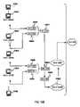
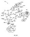
- FIG. 1Cis a generalized diagram of one exemplary computer network suitable for use with the present invention.
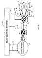
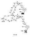
- FIG. 1Ddepicts a typical data network using multi-path
- FIG. 1Eillustrates a simplified data network and flow control system in accordance with a specific embodiment of the present invention
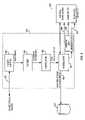
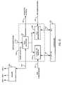
- FIG. 2is a simplified block diagram of one embodiment of a flow control system according to one embodiment the present invention.
- FIG. 3is a functional block diagram of an exemplary passive calibrator of FIG. 2 ;
- FIG. 4is a functional block diagram of an exemplary content flow analyzer of FIG. 3 ;
- FIG. 5is a functional block diagram of an export flow analyzer of FIG. 3 in accordance to one embodiment of the present invention.
- FIG. 6is a functional block diagram of a passive flow analyzer of FIG. 3 according to a specific embodiment
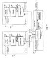
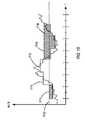
- FIG. 7is a simplified timing diagram of determining network performance metrics with an exemplary flow control system located near a client or a source;
- FIG. 8is a simplified timing diagram of determining network performance metrics with an exemplary flow control system located near a server or a destination;
- FIG. 9is a network diagram of an exemplary passive calibrator with distributed packet capture according to another embodiment of the present invention.
- FIG. 10is a network diagram of distributed passive flow elements according to yet another embodiment of the present invention.
- FIG. 11is a functional block diagram of the distributed passive flow elements of FIG. 10 according to still yet another embodiment of the present invention.
- FIG. 12is a detailed block diagram of an exemplary usage collector according to a specific embodiment of the present invention.
- FIG. 13is a block diagram of a routing server using an associated configuration element receiving one or more protocol feeds, according to one embodiment of the present invention
- FIG. 14is a graphical representation illustrating an exemplary method to determine the amount of bandwidth available that can be used without additional cost in accordance to the present invention
- FIG. 15is a graphical representation illustrating an exemplary method to calculate billable rates in accordance to the present invention.
- FIG. 16is a graphical representation depicting an exemplary method to calculate billable rates using short range forecasting in accordance to the present invention.
- FIG. 17is a representation of an exemplary address or prefix list according to an embodiment of the present invention.
- FIG. 18illustrates an exemplary embodiment of a simplified data network path illustrating three data paths through several network service providers in accordance with the present invention
- FIGS. 19A , 19 B, 19 C, 19 D, 19 E, and 19 F, collectively FIG. 19illustrate network topologies including convergence points and destinations in accordance with an exemplary embodiment of the present invention
- FIGS. 20A , 20 B, and 20 C, collectively FIG. 20are a further illustration of FIG. 19 , with five destination subnetworks associated with IP address prefixes of 24 bit length in accordance with an exemplary embodiment of the present invention
- FIGS. 21A and 21Bare graphical representations illustrating an exemplary data structure for relating convergence point information to address space in accordance with a specific embodiment of the present invention
- FIG. 22is a flowchart depicting an exemplary method of collecting path trace information to determine convergence points in accordance with a specific embodiment of the present invention
- FIG. 24is a graphical representation illustrating another exemplary data structure for relating convergence point information and next-hop information to an address space in accordance with another specific embodiment of the present invention.
- FIG. 26illustrates an exemplary routing table according to a specific embodiment of the present invention
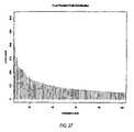
- FIG. 27illustrates a graphical representation of a four-NSP prefix distribution of convergence point analysis information, in accordance with an embodiment of the present invention
- FIG. 28illustrates a network topology for path trace measurement and analysis and a path trace report, in accordance with an embodiment of the present invention
- FIG. 29illustrates a path diversity report, in accordance with an embodiment of the present invention.
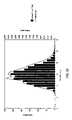
- FIG. 30illustrates a path length report, in accordance with an embodiment of the present invention.
- FIG. 31illustrates a destination distance and traffic volume report, in accordance with an embodiment of the present invention.
- the present inventionincreases the efficiency of routing data between a source and a destination point and vice versa over a network by adjusting a data route with near-real time frequency.
- Topological mapsare created by embodiments of the present invention using data stored in a repository (e.g., characteristics of nodes such as IP addresses, latency, RTT, etc.), received in response to active probes generated by a system in accordance with one embodiment of the present invention.
- a repositorye.g., characteristics of nodes such as IP addresses, latency, RTT, etc.
- a data path as described hereincan be a route, or path, from a first point (e.g., source) to a second point (e.g., destination), and is divided into path portions or “hops,” each of which connects two or more peering points or nodes along a contiguous path between a source and a destination point.
- Data control techniquesgenerally use address prefix lengths that exist in a routing table, typically identified using length designations such as “/24.” The longer the prefix, the more specific the address.
- a /19 prefixrepresents an address space that is a larger subset of addresses than that of a /24 prefix.
- a problemoccurs with an address with a /19 prefix, a larger number of addresses would be affected than a point with a prefix of /24. Thus, a /19 prefix would affect more destinations and/or addresses than a /24 prefix.
- Such techniquesassign arbitrary-length prefixes to route announcements.
- By creating topological network maps using convergence point analysissome embodiments of the present invention, as described below, permit fewer announcements to be used, but with greater specificity. Thus, data traffic volume is reduced and the efficiency of data routing and control is improved.
- Some of the embodiments of the present inventionsignificantly reduce the number of active probes so as to not inhibit the efficiency of data routing by increasing the amount of traffic between the destination and the source.
- Some embodiments of the present inventioncan also provide a system and a method using a data structure that can store information, such as IP addresses, for announcing route changes and updates to a particular data path. The stored data within the data structure then can be modified in response to changes over time that occurs in a network or data route.
- FIGS. 1A , 1 B, and 1 Cillustrate basic hardware components suitable for practicing a specific embodiment of the present invention.
- FIG. 1Ais an illustration of an exemplary computer system 1 including display 3 having display screen 5 .
- Cabinet 7houses standard computer components such as a disk drive, CD-ROM drive, display adapter, network card, random access memory (RAM), central processing unit (CPU), and other components, subsystems and devices.
- User input devicessuch as mouse 11 having buttons 13 , and keyboard 9 are shown.
- Other user input devicessuch as a trackball, touch-screen, digitizing tablet, voice or visual recognition, etc. can be used.
- the computer systemis illustrative of but one type of computer system, such as a desktop computer, suitable for use with the present invention.
- Computerscan be configured with many different hardware components and can be made in many dimensions and styles (e.g., laptop, palmtop, pentop, server, workstation, mainframe). Any hardware platform suitable for performing the processing described herein is suitable for use with the present invention.
- FIG. 1Billustrates subsystems that might typically be found in a computer such as computer 1 .
- subsystems within box 20are directly interfaced to internal bus 22 .
- Such subsystemstypically are contained within the computer system such as within cabinet 7 of FIG. 1A .
- Subsystemsinclude input/output (I/O) controller 24 , System Memory (or random access memory “RAM”) 26 , central processing unit CPU 28 , Display Adapter 30 , Serial Port 40 , Fixed Disk 42 , Network Interface Adapter 44 (e.g., Network Interface Card, or NIC), which in turn is configured to communicate with a network, such as by electrical, radio, or optical means known in the art.
- I/Oinput/output
- RAMrandom access memory
- FIG. 1Bis illustrative of but one suitable configuration. Subsystems, components or devices other than those shown in FIG. 1B can be added. A suitable computer system also can be achieved using fewer than all of the sub-systems shown in FIG. 1B . For example, a standalone computer need not be coupled to a network so Network Interface 44 would not be required. Other subsystems such as a CD-ROM drive, graphics accelerator, etc. can be included in the configuration without affecting the performance of the system of the present invention.
- FIG. 1Cis a generalized diagram of a typical network that might be used to practice an embodiment of the present invention.
- network system 80includes several local networks coupled to computer data network 82 , such as the Internet, WAN (Wide Area Network), or similar networks.
- Computer data network 82such as the Internet, WAN (Wide Area Network), or similar networks.
- Network systems as described hereinrefer to one or more local networks and network service providers that make up one or more paths from a source to a destination and vice versa.
- Network systemsshould be understood to also denote data networks that include one or more computing devices in communication using any networking technology.
- the present inventionis suitable for use with any multi-path network relying upon more than one Internet/network service provider (e.g., a multi-homed network interconnected to other networks), especially those networks that employ Internet Protocol (IP) for routing data, such as flows having one or more packets of information according to the protocol.
- IPInternet Protocol
- FIG. 1Ca specific implementation is not shown in FIG. 1C , one having ordinary skill in the art should appreciate that a data flow control system according to the present invention can be deployed within one or more data networks 82 or configured to operate with network system 80 .
- Computer USER 1is connected to Server 1 , wherein the connection can be by any network protocol, such as Ethernet, Asynchronous Transfer Mode, IEEE standard 1553 bus, modem connection, Universal Serial Bus, etc.
- the communication linkneed not be a wire but can be infrared, radio wave transmission, etc.
- Server 1is coupled to the data network 82 , such as the Internet or, for example, any other data network that uses protocols such as Transmission Control Protocol/Internet Protocol for data communication.
- the data networkis shown symbolically as a collection of server routers 82 .
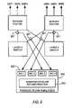
- FIG. 1Dshows the effects of typical multi-path (e.g., ECMP) techniques on a route control system using active calibration alone.
- ECMPmulti-path
- Distance in a router and/or networking contextcan refer to metrics other than physical distance, such as bandwidth or time latencies between routers thus characterizing hops.
- the trafficmay take a different equal-cost path.
- the implications for path calibrationare that the active probes sent across the network between Washington D.C. and San Jose may take the northern path through Chicago 172 while the customer's traffic may take the southern path through Dallas 173 , because while the destination IP address is the same, the source IP address is different. Thus, the path measured may not be the path that is actually taken by the customer's traffic.
- the present inventionintelligently controlled routes containing data traffic using a system and a technique to assure service levels of customer data traffic in accordance with the present invention.
- FIG. 1Eillustrates an exemplary data network within a portion of a network system 80 of FIG. 1C including NSPs 92 , and a flow control system in accordance with a specific embodiment of the present invention.
- Exemplary flow control system 90is configured to communicate with one or more network elements of the data network.
- flow control system 90is shown external of and in communication with the elements of source network 94 , switch 96 , and router 99 , flow control system 90 can be wholly embodied in any of the elements shown, or alternatively, can be distributed, in portions, over each of the elements.
- flow control system 90resides on one or more servers or network elements within exemplary source network 94 .
- An exemplary data networkincludes one or more source networks 94 .
- a source network 94typically is a local network including one or more servers owned and operated by application service providers, managed service providers, content delivery networks, web hosting companies, individual enterprises, corporations, entities and the like. Such service providers typically communicate information to users that are further removed from the multi-homed network service providers 92 , such as NSP 1 , NSP 2 , NSP 3 , . . . and NSPn.
- network service providers 92are coupled to a source network or source node, point, or address so as to be considered a first set of data networks.
- These NSPs, or first set of data networksare in turn coupled to a second set of networks, wherein the second set is connected to multiple other networks, thus establishing one or more paths from a source to a destination and vice versa.
- the multiple connections between router 98 and multiple network service providers 92provide an operator of source network 94 with information to direct data traffic according to the best performing network service provider.
- Switch 96operates to transfer bidirectional data 99 , such as IP data, bi-directionally from source network 94 to router 98 .
- bidirectional data 99such as IP data
- switch 96need not be used to practice the subject invention.
- router 98includes one or more routers running an exemplary protocol, such as TCP/IP, UDP, or BGP (e.g., BGP4, used between autonomous systems implementing networking equipment manufactured by companies such as CisCOTM or JuniperTM implementations), for example, and preferably has route visibility across multiple network service providers (“NSPs”).
- exemplary protocolsuch as TCP/IP, UDP, or BGP
- BGPe.g., BGP4, used between autonomous systems implementing networking equipment manufactured by companies such as CisCOTM or JuniperTM implementations
- NSPsnetwork service providers
- system 90operates to measure end-to-end (i.e., source to destination and destination to source) data traffic 95 in terms of flow characteristics, such as performance, cost, bandwidth, and the like.
- Flow control system 90also generates statistics associated with data paths across multiple network service providers in real time, or near-real time. Such statistics are communicated to source network 94 for providing network engineering personnel, for example, with report information 91 such that on-the-fly reports are created to provide information related to route-change activity, traffic performance as delivered to selected destinations and transit provider usage (i.e., bandwidth), cost, and the like.
- a local computing deviceuses report information 91 from system 90 to generate visual representations on, for example, a graphical user-friendly interface (“GUI”) where the representations are indicative of data traffic along one or more paths (e.g., paths between a source and a destination).
- GUIgraphical user-friendly interface
- Network or systems administration personnel, or any entity responsible with flow control, with access to source network 94can provide control information 93 (including, for example, flow characteristics) to flow control system 90 to modify system operation by, for example, changing data traffic flow from an under-performing current, or default, path to a better performing path. Intervention by network administration personnel, however, is not necessary for flow control system 90 to operate in accordance with the present invention.
- Flow control system 90further functions to compare specific data traffic flows (i.e., both uni- and bi-directional traffic flows outbound from and inbound into the data network) to determine whether a particular traffic flow meets one or more rules of an associated flow policy.
- a flow policyincludes a set of one or more rules that is associated with a particular data traffic flow related to particular system user (e.g., as denoted by IP address prefix).
- Minimum criteriacan represent the lower levels of a range of values that defines acceptable routing behavior associated with a particular traffic flow characteristic.
- a rulecan set: the maximum acceptable cost, with or without regard to network service provider cost; the maximum load or bandwidth usage associated with traffic flows through specific providers; a range of acceptable (or non-acceptable) service providers; the maximum acceptable latency or loss over one or more paths across multiple network service providers; acceptable ranges of performance for each network service provider, such as maximum burst limits, minimum performance commitments and range of costs (i.e., cost structures with regards to time of day, type of traffic, etc.); and any other data flow characteristic that can influence the measurement or the control of data traffic.
- Flow control system 90further operates to detect when one or more rules, or flow policies, are violated and then to take remedial action. That is, flow control system 90 enforces policies associated with data traffic flow by correcting detrimental deviations in performance (i.e., service level assurance), costs or bandwidth (i.e., load in terms of percent capacity available per path). Flow control system 90 makes such corrections based on real- or near-real time traffic analysis, local path diversity (i.e., modifying one or more egress paths from a data network), and visibility (as determined, for example, by active probing) into downstream available paths. For example, for a destination related to a specific traffic flow, flow control system 90 directs, or re-directs, traffic to one or more alternative paths to resolve a particular flow's deviation in terms of flow characteristics, from its flow policy.
- detrimental deviations in performancei.e., service level assurance
- bandwidthi.e., load in terms of percent capacity available per path.
- Flow control system 90makes such corrections based on real
- FIG. 2illustrates a specific embodiment of flow control system 90 of FIG. 1D .
- flow control system in FIG. 2is a reactive flow control system. That is, a reactive flow control system is designed to react to policy violations indicating sub-standard routing of data traffic over one or more data networks or service providers (i.e., addresses pass-fail criteria) rather than optimizing performance at some targeted level of acceptable operation.
- flow control system of FIG. 2operates to optimize performance and/or usage by selecting the path having the most desired specific performance characteristic, for example, that at least meet the minimum level of service.
- Flow control system 200can include controller 205 , passive calibrator 203 , active calibrator 208 , configuration element 211 , and usage collector 214 , each of which can be realized in hardware, software, or a combination thereof.
- controller 205 , passive calibrator 203 , active calibrator 208 , configuration element 211 , and usage collector 214are software modules designed to perform specific processes, as described herein, in accordance to the present invention. Such modules can reside in one or more computing devices, such as the computing devices shown in FIG. 1A , or alternatively, over one or more user-type machines (i.e., servers) coupled over a data network or network system.
- Exemplary passive calibrator 203 , active calibrator 208 and usage collector 214are coupled to controller 205 to, in part, provide flow characteristics of data traffic.
- Controller 205receives monitored flow characteristics as well as flow policies to be enforced. User or machine-generated rules pertaining to the flow policies 206 for route control are provided to controller 205 . Specific parameters or operating guidelines for the present invention can be entered at controller 205 to ensure flow control system 200 maintains an appropriate level of operation, monitoring, and alarm status.
- Controller 205is configured to determine if a flow policy is violated, and upon detection of such a violation, then to select a remedial action to resolve the violation.
- Configuration element 211is coupled to controller 205 to receive information to initiate remedial actions and is configured to communicate such actions to data director 220 . Thereafter, data director 220 implements the corrective action to resolve the pending violation, for example, by changing the traffic flow from the current path to a better performing path.
- flow control system 200can include traffic repository 221 and flow policy repository 218 .
- Exemplary traffic repository 221 and flow policy repository 218are databases, such as a storage device, configured to store a large number of records in one or more data structures.
- Traffic repository 221is designed to store and to communicate information related to traffic flow and route characteristics
- flow policy repository 218is designed to store and to communicate policy information or rules to govern the performance and cost of each of the data traffic flows.
- One having ordinary skill in the art of database managementshould appreciate that many database techniques may be employed to effectuate the repositories of the present invention.
- flow control system 200 of FIG. 2monitors egress and ingress data flow 201 , such as IP data traffic, to determine whether data flow 201 to and from source network is within the performance tolerances set by the associated flow policy.
- Flow control system 200receives data flow 201 by replication, such as by a network switch, by using a splitter, such as an optical splitter, or any other tapping means know to those having ordinary skill in the art.
- Data flow 202which is exactly, or near exactly, the same as the information contained within data flow 201 , is provided to passive calibrator 203 .
- Passive calibrator 203monitors the data traffic of data flow 201 and communicates information 204 related to the traffic and traffic performance to controller 205 .
- Controller 205is configured to receive policy data 206 representing one or more policies that correspond to a particular traffic flow, such as a particular data flow.
- the particular data flowcan be associated with a certain user identified by a destination prefix, for example.
- controller 205determines the levels of performance, cost, and/or utilization that the particular traffic is to meet. For example, controller 205 determines whether a particular traffic flow of data flow 201 is meeting defined performance levels (i.e., service levels) as defined by one or more requirements or criteria, such as inbound and outbound network latency, packet loss, network jitter, and the like.
- Active calibrator 208functions to send and to receive one or more active probes 207 , of varying types, into and from the data networks. These probes are designed to measure network performance including, but not limited to, the path taken across one or more available providers (i.e., to determine if a provider is a transit AS rather than peer AS), next hop-in-use, and other network parameters.
- controller 205sends an active probe request 209 to active calibrator 208 . Such a request is required if controller 205 determines that additional information regarding alternative paths or network system characteristics are necessary to better enforce policies in reactive flow control systems, or alternatively, to prevent such policy violations in optimized flow control systems.
- Usage collector 214is configured to receive NSP data 217 representing one or more network provider configurations. Generally, such configurations include the number of paths (“pipes”) associated with each provider and the size thereof. Additionally, NSP data 217 can relate to a provider's cost or billing structure and can also include each provider's associated set or subset of addresses, each provider's billing methods (i.e., byte/min, etc.), etc. Moreover, usage collector 214 is configured to collect usage information 213 from the network elements, such as switches, border routers, provider gear, and other devices used to transport data over data networks. Usage collector 214 is configured to provide controller 205 with provider utilization and billing information 215 , which represents aggregated data based upon NSP data 217 and usage information 213 .
- provider utilization and billing information 215which represents aggregated data based upon NSP data 217 and usage information 213 .
- Usage data or utilization datacan be measured in various ways to include connection or link time, data packet volume, and/or other metrics not included here specifically.
- Other utilization and billing information 215includes data that represents cost, billing, utilization, etc., for each network service provider of interest.
- NSP data 217can be provided to usage collector 214 in a variety of ways.
- data describing, defining, controlling, or modifying data paths as used for the data flows described hereincan be provided by an entity having authority to do so, such as a network engineer entering the data into a computing device using a GUI in source network 94 of FIG. 1E , which for example, can represent information displayed in FIG. 27 .
- usage collector 214is configured to monitor usage characteristics defining a network service provider's data traffic capacity, costs, etc.
- Usage data 213 provided to usage collector 214includes usage information and characteristics from network elements, such as switches, border routers, routers, provider gear, and other devices used to transport data over data networks. Usage refers to the data (i.e., data such as X Mb samples at time ( 0 )) that represents instantaneous or near instantaneous measurement of characteristics (i.e., usage characteristics, data volume, etc.) that define, for example, the load and available capacity of each network service provider. Utilization is the usage rate over time.
- NSP 1For example, suppose the usage collector monitoring NSP 1 measures the system's utilization of NSP 1 , or capacity over time, as X Mb at time( 0 ) and Y Mb at time( 1 ). This raw data, or usage, is used to calculate utilization, or usage rate for NSPI (e.g., Y ⁇ X/time( 1 ) ⁇ time( 0 )).
- Bandwidthis the total capacity for each path or hop available for traffic flow. In one embodiment, the usage can be measured in any hop in any path at any number of hops or networks from a first point. Load is typically defined as the amount of capacity a particular path is used to carry data traffic and can be expressed as load/bandwidth.
- Usage collector 214is designed to generate utilization and billing information 215 based upon usage information 1213 and NSP data 217 . Since each of the providers has different cost and billing structures, as well as methods of determining usage costs, usage collector 214 operates to aggregate usage information 213 accordingly to provide controller 205 with utilization and billing information 215 . Software applications or other means (e.g., by human manipulation) may be used to implement utilization and billing information for financial accounting purposes.
- Usage collector 214then provides the utilization billing information 215 to controller 205 for each network service provider of interest.
- the usage collectorcan provide additional information based upon the provider usage information, to the controller, as needed to better effectuate route control.
- Configuration element 211is designed to communicate routing changes in the network to data director 220 . Once configuration element 211 sends one or more routing changes, data director 220 then moves the subject data flow 201 from a current path to another path (e.g., from NSPI to NSP 2 to NSPn or a first path of NSPI to a second path of NSPI). Data director 220 thus operates to distribute traffic to these destinations across multiple network service provider links based on, for example, the cost and performance measured across each link.
- configuration element 211communicates one or more routing changes 210 with data director 220 , for example, by using a routing protocol such as BGP.
- Configuration element 211functions to dynamically control routing behavior by modifying the source address, for example, of the traffic passing through configuration element 211 .
- the source addressis modified in a way that improves application performance as well as cost requirements.
- active calibrator 208provides active mechanisms within system 200 for determining the nature of downstream or upstream paths. This information is typically not available in any conventional protocol used on data networks such as the Internet, and is collected external to the normal processes of networking. As shown in FIG. 2 , active calibrator 208 is coupled to controller 205 to provide at least a destination prefix that is not meeting the policy requirements, such as minimum performance level. Once received, active calibrator 208 then initiates a calibration process that determines some, most, or all of the available network paths to the destination address as well as performance levels. Controller 205 is designed to select the most suitable probes that active calibrator 208 is to use, based on the particular policy requiring enforcement or correction, and thereafter to initiate active probing of network paths using active calibrator 208 .
- active calibrator 208resides in data director 220 within, or alternatively, can be integrated into controller 205 .
- routerssuitable to practice the present invention.
- One example of suitable active probesis the RMON probe.
- SAAService Assurance Agent
- RMONremote monitoring
- SAAallows routers to measure and report network-originated application round trip times (“RTT”).
- RTTnetwork-originated application round trip times
- An exemplary active calibrator 208can use ICMP (Internet Control Message Protocol) echo request or other ping-type probes, lightweight TCP-based probes, Sting probes, “pathchar” probes, lightweight probes using User Datagram Protocol (“UDP”) packets with a predefined TTL (time to live), traceroute probes, or other active probes that are suitable for use by active calibrator 208 in accordance with the present invention.
- ICMPInternet Control Message Protocol
- UDPUser Datagram Protocol
- TTLtime to live
- traceroute probesor other active probes that are suitable for use by active calibrator 208 in accordance with the present invention.
- weightwhether heavy or lightweight, is a local measure of whether a particular data route is preferred over another. A weight is given to a data route by a particular router using a route map and is intended for use only by that router.
- the lightweight probes referred to hereinindicate that they are intended for a specific predetermined router, per a route map created in accordance with an embodiment of the present
- probesare received by active calibrator 208 of FIG. 2 and can be sent out by their source addresses. Such probes can be sourced and received on an exemplary stats computer system resident, for example, in the local premises, or as a stats process on a router.
- the active calibrator and its use of probesoperate in accordance to probes described in a U.S. Patent Application, entitled “System and Method to Assure Network Service Levels with Intelligent Routing,” having U.S. patent application Ser. No. 09/833,219 and filed on Apr. 10, 2001, and is incorporated by reference for all purposes.
- Exemplary passive calibrator 203 of FIG. 2is configured to receive, without interfering with, network communication data 201 , such as customer network or Internet traffic.
- Network communication data path 201i.e., including one or more IP data traffic flows
- passive calibrator 203includes the default or currently routed path of the data traffic that is provided to passive calibration element 203 from data director 220 .
- the currently routed pathis, for example, the path (e.g., hop-by-hop) between routers that a packet would take, as determined by standard routing protocols, flow control policy, or other performances parameters.
- Passive calibrator 203is coupled (i.e., electrically, optically, by radio waves, etc.) to controller 205 to provide information which indicates whether the specific IP data traffic is within the range of acceptable performance metrics, such as determined by a flow policy.
- Passive calibrator 203operates to instantaneously monitor all traffic received via data flow 202 and is designed to overcome the complications of relying solely on active traffic analysis, such as EMCP, as shown with respect to FIG. 1D .
- active traffic analysissuch as EMCP
- passive calibrator 203operates to overcome the complications of performing only active traffic analysis in the presence of multi-path (e.g., ECMP).
- multi-pathe.g., ECMP
- passive calibrator 203is coupled to store, fetch and update traffic and route information stored in traffic repository 221 (connection not shown).
- traffic repository 221is a database configured to store and to maintain data representing traffic and route information, which is useful to the end user employing a flow control system, such as system 200 of FIG. 2 , as well as the operators of, for example, a network service provider.
- the data within traffic repository 221includes long term statistics describe the flow characteristics of the data traffic. These statistics can be used for reporting, analysis purposes, and providing general feedback to a user of a flow control system according to the present invention.
- Such feedbackcan consist, for example, of types of traffic being sent, source addresses, destination addresses, applications, traffic sent by ToS or DSCP (“DiffServ Code Point”) setting (which might be integrated into a differentiated billing system), volume of traffic, and the like.
- DiffServ Code Pointtraffic sent by ToS or DSCP (“DiffServ Code Point”) setting (which might be integrated into a differentiated billing system), volume of traffic, and the like.
- Traffic repository 221where, for example, a reporting engine or some other analysis application can access to the statistics.
- the information stored in traffic repository 221includes data representing such traffic route characteristics arranged in any suitable data structure as would be appreciated by one skilled in the art.
- FIG. 3is a detailed functional block diagram showing exemplary elements of a passive calibrator 303 according to an embodiment of the present invention.
- Passive calibrator 303includes, for example, passive flow analyzer 330 , export flow analyzer 331 , and content analyzer 332 .
- passive flow analyzer 330performs passive analysis on the traffic to monitor current traffic flow characteristics so the controller can determine whether the monitored current traffic flow meets associated policy requirements.
- Export flow analyzer 331performs passive analysis on exported flow records from a network device, such as from those devices (e.g., router) that advertise traffic type, source and destination addresses, and other information related to the traffic that it travels across service provider links.
- a network devicesuch as from those devices (e.g., router) that advertise traffic type, source and destination addresses, and other information related to the traffic that it travels across service provider links.
- An example of such a network deviceis Cisco's NetFlowTM product.
- passive flow analyzer 330operates in accordance to the passive flow analyzer described in the above-mentioned U.S. patent application of Ser. No. 09/833,219.
- the passive flow analyzerprovides the one or more prefix lists, or portions thereof, to the controller for use in determining a policy violation, for determining which routes or path comply with the flow policy, which path is the optimum path for routing data, and the like.
- An exemplary prefix listthat can be generated by export flow analyzer 331 and content flow analyzer 332 , as well as passive flow analyzer 330 .
- List 1970includes aggregate flow information for each address 1920 and/or prefix.
- record 1975include the following data: for address 1.2.4.7, this address was monitored four times during the sampling time interval (delta)t with a total flow volume of 360 bytes.
- new prefix list 1980includes address 1.2.4.9 having one occurrence (first time) over (delta)t interval.
- data representing address, occurrence, number of bytes, time interval, etc.can be used to manipulate the data such in a way that the controller can easily obtain.
- Content flow analyzer 332is typically used when the main source of traffic flow 340 is web site or other content.
- Content source 341can be configured such that special or premium content 342 that must be optimized can be identified by the flow control system by using, for example, an embedded URL 343 .
- URL 343redirects the client to a content server running on the content flow analyzer 332 .
- Content flow analyzer 332receives a request for the content element, which is generally an image file (e.g., 1 ⁇ 1 GIF) and is invisible or imperceptible in relation with the main original content, and responds to the client with the content element 344 .
- Content flow analyzer 332then stores or logs this transaction in log files and, by using the log files, content flow analyzer 332 is able to perform aggregation and assemble content prefix list 334 .
- the list 334is passed along to controller 205 , for example, for active service level monitoring and policy enforcement.
- FIG. 4illustrates a functional block diagram of an exemplary content flow analyzer 432 .
- Content flow analyzer 432handles requests 420 for a small element of content, which is, for example, a 1 ⁇ 1 pixel image file that is imperceptible (although it need not be) on the resulting page.
- the small elementis associated with the premium or generally specific pages of a larger set of content.
- the small elementis, for example, a small redirect URL embedded within the content.
- aggregator 454classifies prefixes according to frequency of occurrence and provides aggregated (i.e., grouped) prefixes 426 to prefix list generator 455 .
- Prefix list generator 455creates destination prefix list 428 according, for example, to a prefix's importance in relation to the overall operation of the system as defined by the aggregated or grouped prefixes 426 . For example, each monitored traffic flow is examined to determine the performance characteristics associated with a destination prefix or address.
- Aggregate prefixes 426can be generally classified in terms of flow frequency, and average or total flow volume.
- Prefix list generator 455sends updates to current prefix list 428 to controller 205 of FIG. 2 , and also notifies other elements of the system with new prefix notification signal 432 when a new prefix is observed.
- Prefix list generator 455stores the prefix information 430 to persistent storage for reporting and analysis purposes.
- a new prefixprovides an additional alternate path or path segment that was unknown until a certain point of time.
- the new alternate path or path portion associated with the new prefixcan provide for flow policy compliance, and thus can be used to re-route or modify the routing of data in accordance with am embodiment of the present invention to correct a policy violation.
- FIG. 5illustrates a functional block diagram of exemplary export flow analyzer 531 .
- Export flow analyzer 531includes format interpreter 549 , parser 550 and prefix list generator 552 .
- Format interpreter 549is configured to receive export flow datagrams 520 from the network elements designed to send them. Format interpreter 549 then communicates individual flow information 522 to parser 550 .
- Parser 550operates to interpret destination IP elements from the flows monitored by the passive calibrator. Parser 550 also aggregates traffic flow according to total flow volume or transportation rate (e.g., in bytes/time unit) as well as flow frequency of destination addresses, for example, into aggregate elements. Thereafter, parser 550 sends the aggregate elements 524 to aggregator 551 .
- total flow volume or transportation ratee.g., in bytes/time unit
- Destination prefix list 528is generated by prefix list generator 552 by, for example, ranking and organizing traffic flow characteristics related to prefixes in order of relative importance.
- List 528contains data representing an aggregation of prefixes and is organized by relevance, as determined by the system or an entity to ensure policy enforcement. For example, one or more prefixes can be ordered in terms of flow frequency and average or total flow volume in relation to prefixes available in the overall system.
- Prefix list generator 552sends updates to the current prefix list to controller 205 of FIG. 2 and also notifies other elements of the system when a new prefix is observed via a new prefix notification signal 532 .
- Prefix list generator 552stores prefix information 530 to persistent storage for reporting and analysis purposes.
- FIG. 6illustrates a function block diagram of an exemplary passive flow analyzer 630 of FIG. 3 .
- passive flow analyzer 630is designed to generate prefix list 634 and new prefix notification signal 635 and generates aggregated flow data 680 , including network performance and usage statistics (e.g., data) grouped into relevant characteristics. For example, prefixes of a certain size can be aggregated, or grouped, from highest traffic volume to lowest as observed over time.
- the aggregated flow data 680is communicated to controller 605 and are used by the controller to determine whether the current traffic flow violates or fails to conform to an associated flow policy for a given destination.
- the passive flow analyzer 630also functions to store aggregated flow data 680 in traffic repository 621 , where it can be used for characterizing historical route and traffic flow performance.
- a prefix list generatoris not included in the passive flow analyzer of FIG. 6 .
- Passive flow analyzer 630uses a copy of the traffic 602 via a passive network tap or spanned switch port, as shown in FIG. 2 , to monitor the network performance for traffic. Passive flow analyzer 630 also can monitor and characterize UDP traffic patterns for detection of anomalous behavior, such as non-periodic traffic flow, or the like. Passive flow analyzer 630 can use various neural network techniques to learn and understand normal UDP behavior for the application in question, and indicate when that behavior has changed, possibly indicating a service level violation which can be verified or explained with well known active probing techniques.
- passive flow analyzer 630is designed to be “application-aware” according to how each of the particular traffic flows is classified. Traffic can be classified according to the classifier described in the above-mentioned U.S. patent application Ser. No. 09/833,219. Passive flow analyzer 630 can inspect the payload of each packet of traffic 602 to interpret the performance and operation of specific network applications, such as capture and interpretation of the Realtime Transport Control Protocol (“RTCP”) for voice over IP (“VoIP”), for example.
- RTCPRealtime Transport Control Protocol
- VoIPvoice over IP
- passive flow analyzer 330includes packet capture engine 650 , packet parser 651 , correlation engine 652 , and aggregator 653 .
- Packet capture engine 650is a passive receiver configured to receive traffic (e.g., IP data traffic) coming into and out of the network. Control signals are exchanged between aggregator 653 and controller 605 (e.g., requests from controller 605 ). Capture of traffic is used to facilitate traffic analysis and for determining whether a current traffic route meets minimum service levels or policy requirements. Packet capture engine 650 is designed to remove one, several or all packets from a traffic stream, including packets leaving the network and entering the network.
- Packet capture engine 250operates to remove certain packets up, for example, from the network drivers in the kernel to user space by writing custom network drivers to capture part of a packet. Using DMA, the partial packet can be copied directly into user space without using the computer CPU. Such packets are typically removed according to one or more filters before they are captured. Such filters and the use thereof are well known in the art and can be designed to, for example, remove all types of TCP traffic, a specific address range or ranges, or any combination of source or destination address, protocol, packet size, or data match, etc. Several common libraries exist to perform this function, the most common being “libpcap.” Libpcap is a system-independent interface for packet capture written at the Lawrence Berkeley National Laboratory. Berkeley Packet Filter is another example of such capture program.
- TCP elements parsed from the TCP headersare especially useful in determining whether a policy is being enforced, in terms of performance.
- An increasing amount of trafficdoes not rely on TCP and instead uses UDP.
- UDPdoes not contain the necessary information to determine service levels according to conventional approaches.
- the present inventionmight employ a statistically relevant amount of collateral TCP traffic going to the same prefix or a series of active probes to the same destinations, and/or have the analyzer parse deeper into the packet and understand the traffic at the application layer (e.g., layer 7), for example.
- the application layere.g., layer 7
- reducing the variance in inter-packet arrival timesmight be desirable.
- Many real time protocols and standardssuch as H.323 as defined by the International Telecommunications Union (ITU) can report the jitter in back channel communication known as the RTCP (“Real-Time Transport Control Protocol”), which is used to distribute time-dependent media data via IP multicast with feedback.
- RTCPReal-Time Transport Control Protocol
- passive flow analyzer 630 of FIG. 3is “application-aware,” it can capture and observe the contents of the RTCP and be aware when the underlying network path is not meeting minimum jitter requirements. This can trigger an SLA violation in the same manner that 30% packet loss would when monitoring packet loss.
- Correlator 652operates to interpret and to group the packet elements (e.g., TCP and IP) from the packets to determine the current service level of the flow and then groups the packets into a specific traffic flow. Flows are reconstructed, or grouped, by matching source and destination IP addresses and port numbers, similar to the process of stateful monitoring of firewalls. Correlator 652 determines the current service level by measuring several traffic characteristics during a TCP transaction. For example, correlator 652 determines the round trip time (“RTT”) incurred on a network, and hence, this serves as a measure of latency for the network traffic.
- RTTround trip time
- FIG. 7shows how correlator 652 of passive flow analyzer 630 of FIG. 6 , placed near a source (e.g., client having a source address), can determine the network latency (“NL”) and server response time (“SRT”) for a TCP traffic stream.
- FIG. 8shows how correlator 652 of passive flow analyzer 630 of FIG. 6 , placed near a destination (e.g., server having a destination address), can determine the network latency (“NL”) and server response time (“SRT”) for a TCP traffic stream
- Correlator 652 of FIG. 6determines NL, for example, by estimating the difference 791 of FIG. 7 in time between a TCP SYN packet and its corresponding TCP SYN ACK packet.
- the difference in time between SYN and SYN ACK 791is a rough estimation of the RTT excluding the small amount of time 790 that the server takes to respond to SYN.
- the SYN ACK packetis handled in the kernel of most operating systems and is generally assumed to be near zero. For each new TCP stream that is initiated from the source, correlator 652 can observe a time instantaneous value for network latency.
- Packet lossis calculated, as a percentage, by correlator 652 by maintaining the state of all of the retransmitted packets that occur. From this value, correlator 652 calculates percentage packet loss from a total count of segments sent.
- Correlator 652also determines SRT 792 of FIG. 7 , for example, by estimating the delta time (i.e., difference) 793 between, for example, the HTTP GET message 795 and the first data segment received and then by subtracting the previous value for the RTT. This assumes that the previous value for the RTT has not changed beyond an operable range since the TCP handshake occurred.
- the measurement shown by 794indicates that measured congestion increases in the path as SRT 792 correspondingly increases. For purposes of this example, it is assumed that the data segments in the initial HTTP GET are sent back to back.
- the passive flow analyzer 630is deployed close to (i.e., minimal or negligible latency due to geographically different locations) the clients requesting content from the IP data network, such as the Internet.
- Correlator 652also determines SRT 892 of FIG. 8 , for example, by estimating the delta time between the HTTP GET message 893 and the first data segment 894 .
- the passive flow analyzer 630 of FIG. 6is deployed on the server end as will occur for most content delivery installations.
- SRT 892 determined by correlator 652depends on its location along the path that the traffic traverses. If passive flow analyzer 630 of FIG. 6 is on the client side, server response time 792 of FIG. 7 can be estimated as the delta in time between the HTTP GET Request message and the first data segment returned minus the RTT observed before the GET Request as shown in FIG. 7 . If passive flow analyzer 630 of FIG. 6 is closer to the server side, the estimation is essentially the delta in time between the GET Request and the response as shown in FIG. 8 .
- TCP Congestion Window(“cwnd”) and by identifying the delta in receive time between segments that were sent back to back by the server, where the TCP congestion window controls the number of packets a TCP flow may have in the network at any time.
- Correlator 652is coupled to provide the above determined exemplary flow characteristics to aggregator 653 .
- aggregator 653primarily operates to group flows going to (or alternatively, coming from) each set of specific destinations together into one grouping.
- Aggregator 653uses the service level statistic for each of the individual flows, received from Correlator 652 , to generate an aggregate of service level statistics for each grouping of flows that are to go to the same destinations in the data network, such as the Internet.
- Aggregator 653is also coupled to traffic storage 621 to store such aggregated (i.e., grouped by address prefix) traffic flow characteristics. Traffic flow characteristics (or traffic profiles) are then used for future statistical manipulation and flow prediction.
- traffic storage 621is the equivalent, or the same, as storage 221 of FIG. 2 .
- the granularity of the destinationsis the same as the granularity of changes that can be made in the routing table.
- flow control system of FIG. 2can install routes with prefixes of any length (i.e., 0/ to /32), though the general practice is not to do so.
- Aggregator 653can start aggregating flow statistics at the /32 level (i.e., class C networks) and continue all the way up to the /8 level (i.e., class A networks) into a data structure, such as a patricia or radix trie, or a parent-child data structure, or the like. In this way, it is possible to seek very quickly the necessary granularity of the routing change that needs to be made to ensure the service level is met.
- Aggregation techniques employed by aggregator 653are used. to maintain the system 200 of FIG. 2 to acceptable performance service levels, such as determined by one or more flow policy requirements. Since network performance has been shown not to generally follow conventional statistical distribution, such as Gaussian or Poisson distribution, average calculations for service levels across all flows are not as reliable a measurement of a typical performance behavior during a time interval. If the service level agreement (SLA) or policy, however, states that the average service level must be maintained, then the outlying occurrences of poor performance will cause the average to be skewed, thus requiring corrective action to restore the minimum service levels being offered.
- SLAservice level agreement
- a meaningful way to describe typical service levels being offered across data flowscan be to use median values, rather than average values, in some embodiments of the present invention. A person having ordinary skill in the arts will appreciate that either technique is possible and will depend on the definition of the service level that must be maintained.
- FIG. 9illustrates how passive flow analyzer 930 , according to another embodiment of the present invention, is capable of packet capture and flow reconstruction across more than one network interface, each interface represented by a network interface card (“NIC”).
- NICnetwork interface card
- many switch fabricsare constructed in a manner by tapping into a single point in the data stream or replicating a single port. The switch does not guarantee that passive flow analyzer 930 will see all of the traffic in both directions. Bi-directional traffic is required for optional flow reconstruction for passive analysis.
- the switch fabric showncan be passively tapped at tap points 921 at four places (as shown) and connected to passive flow analyzer 930 at four different network interface cards (NIC) 922 .
- Passive taps at tap points 921can be mirrored switch ports, optical/electrical passive taps, or the like.
- Passive flow analyzer 930can include either a single or combined aggregated flow reconstruction element 953 that can collect captured data from multiple network interfaces in order to perform flow reconstruction.
- FIG. 10illustrates yet another embodiment of the present invention where passive flow analyzer 630 of FIG. 6 is distributed in nature.
- FIG. 10shows traffic flow 1020 bi-directionally traveling via several local traffic source points.
- Distributed local passive flow agents 1025can be tapped passively at tap point 1024 into traffic flow 1020 .
- Passive flow agents 1025are distributed such that each agent monitors and conveys individual flow characteristics.
- the traffic sourcesare distributed across a layer 3 infrastructure, for example, and are separated by one or more routers 1026 . This arrangement prevents the passive flow analyzer 930 of FIG. 9 from collecting information across the same layer 2 switch fabric as in FIG. 9 .
- Each of the passive flow agents 1025performs local flow reconstruction and then exports flow data records 1027 over the network to a central passive flow analyzer 1028 , performs flow aggregation and service level analysis across all of the distributed passive flow agents 1025 .
- FIG. 11illustrates a more detailed functional block diagram depicting multiple passive flow agents 1125 separately distributed and a single central passive flow analyzer 1128 .
- Each passive flow agent 1125includes packet capture 1150 , parser 1151 and correlator 1152 functions on each of the local traffic flows.
- Correlator 1152exports flow records 1129 with substantial data reduction to central passive flow analyzer 1128 . Substantial data reduction reduces the amount of information forwarded to the central passive flow analyzer, which can be effectuated by using well-known encoding techniques.
- Central passive flow analyzer 1128accepts flow export records 1129 from each passive flow agent 1125 and central aggregator 1153 performs prefix aggregation on each of the exported flows. Thus, the centrally aggregated flow information can be used to determine if a particular policy violation is occurring.
- FIG. 12illustrates a detailed block diagram of usage collector 214 of FIG. 2 .
- Usage collector 1215operates to collect usage information 1273 from network providers, such as byte counters (i.e., the amount of traffic transmitted to and received from network service providers). Usage collector 1215 uses this information to calculate network service provider utilization, load, etc., of data paths associated with the provider.
- network providerssuch as byte counters (i.e., the amount of traffic transmitted to and received from network service providers).
- Usage collector 1215uses this information to calculate network service provider utilization, load, etc., of data paths associated with the provider.
- Usage collector 1215also operates to reconstruct provider billing records. Usage collector 1215 accepts provider configuration information 1271 related to each network service provider (NSP) connection. This NSP configuration information 1271 details provider interfaces on the various routers 1272 (e.g., egress routers), provider next-hop IP addresses traceroute probes (to verify the current provider in use with trace probes), billing period start and end dates, circuit bandwidth for calculating the utilization and price per megabit/sec, minimum bandwidth commitment, burstable rates, provider sampling interval, provider billing algorithm, a utilization alarm threshold and the like.
- NSPnetwork service provider
- exemplary raw collector 1274sends a query 1290 (e.g., SNMP) to collect interface raw byte counters from routers 1272 on each of the provider circuits at a specified sampling interval.
- Provider circuitsinclude paths, pipes (virtual and/or physical), T1, and the like.
- Raw Collector 1274places the raw byte counters 1280 into persistent storage for later reporting and analysis.
- Raw collector 1274sends the raw information to two other components: utilization monitor 1275 and bill reconstructor 1276 .
- Utilization monitor 1275calculates the ingress and egress circuit utilization for each provider using the raw byte counts and the NSP configuration information 1271 .
- NSP configuration information 1271includes the bandwidth of the provider's circuits.
- Utilization information 264includes data representing utilization trends for use with short range forecasting models (e.g., ARIMA, exponential smoothing, etc.) such that utilization monitor 1275 can determine whether bandwidth is trending up or down (i.e., increasing or decreasing in size) for a given service provider.
- short range forecasting modelse.g., ARIMA, exponential smoothing, etc.
- Bill reconstructor 1276uses the billing information from NSP configuration data 1271 to reconstruct the current provider billable rate for the current billing period.
- Billing informationincludes information explaining the methods that specific providers use to calculate costs, such as a billing rate. Such methods of calculating bills for using a network provider are well known in the art.
- Bill reconstructor 1276applies similar provider billing methods to the raw byte counters from raw collector 1274 to generate the bill and related billing rates, etc. The generated bills, which can be mapped into dollar amounts, are typically estimates since the sample times between the provider and usage collector 1215 generally do not match exactly.
- Bill reconstructor 1276will send billing information 1261 to controller 1202 for use in peak avoidance and least cost routing. Peak avoidance can be defined as a method of avoiding using a path or path portion at a higher a billing rate, such as shown in FIG. 15 .
- Least cost routingrefers to a method of using or defaulting traffic to the least expensive provider.
- controller 1202uses data from billing message 1261 , including billing rates, to determine an alternate path based in part on a path's free bandwidth (i.e., path does not incur additional cost to use), in accordance with the flow policy.
- configuration element 211is coupled to controller 205 and to data director 220 .
- Controller 205provides the best path, as defined by a particular flow policy, to reach a destination prefix to configuration element 211 .
- Configuration element 211operates to change the default routing behavior (i.e., current path) for the destination requiring corrective action.
- Configuration element 211changes the routing behavior by, for example, sending a modified routing table of addresses to data director 220 .
- data director 220informs controller 205 that a route change has been implemented. Thereafter, controller 205 communicates signal 230 back to passive calibrator 202 to clear its state and to resume monitoring the destination. The destination is monitored to ensure that the updated path of the routing table, or path, meets minimum service levels (e.g., no violations of SLA, or no unacceptable deviations from agreed upon performance metrics as defined by the associated flow policy).
- minimum service levelse.g., no violations of SLA, or no unacceptable deviations from agreed upon performance metrics as defined by the associated flow policy.
- configuration element 211resides in a route server. In another aspect, configuration element 211 resides in a router and is configured to modify a route map or table. In yet another aspect, configuration element 211 is adapted to provide configuration information, or routing table. In still yet another aspect, the path information is stored within the configuration element 211 according to whether it is related to inbound or outbound traffic.
- FIG. 13shows an example of yet another embodiment of the present invention, where configuration element 211 of FIG. 2 resides in a network element, such as route server 1391 .
- Configuration element 1384 of FIG. 13operates similarly to other adaptations of configuration elements described herein. That is, configuration element 1384 modulates the current or default routes of data traffic and thus modifies the default routing behavior, for example, in a local deployment (e.g., Point of Presence, or “POP”).
- Route server 1391 (“RS”)receives a full set or subset of routing tables from the data networks of interest.
- the routing tablesare received into route server 1391 by way of one or more default BGP4 feeds 1392 into BGP4 Engine 1382 from a full set or subset of the local transit providers.
- BGP4 Engine 1382integrates, or merges, the routes into a single BGP4 routing table 1383 of best available routes.
- route server 1391maintains an iBGP session with all of the internal BGP capable routers rather than maintaining the BGP4 sessions as shown in FIG. 13 . With a single iBGP session there is no need to configure all of the BGP sessions with the network service providers before making route changes.
- Configuration element 1384is designed to receive one or more BGP4 routing tables 1383 from BGP4 engine 1382 and can be adapted to receive one or more control signals and data resulting from the control processes of controller 1305 . In operations, configuration element 1384 receives, from controller 1305 , the necessary routing changes to be implemented in default routing table 1388 . Then, configuration element 1384 incorporates one or more changes in modified routing table 1389 .
- configuration element 1384operates to modify BGP4 routing table 1383 and to generate one or more modified BGP4 routing tables 1388 .
- Modified BGP4 routing table 1388includes changed routing 1389 , advertisements of more specific routes, etc.
- New modified BGP4 routing table 1388is then fed to all BGP clients in the network, which then is used to guide traffic to the destination.
- the ingress point into a networkis determined typically by the advertisements of routes made to downstream providers and a provider policy (set of rules that is set up by such providers).
- a provider policyset of rules that is set up by such providers.
- the network service providere.g., “ISP”
- Controller 205 of FIG. 2is designed to receive performance characteristics, such as latency, loss, jitter, etc., as monitored by the calibrator elements as well as usage characteristics, such as bandwidth, costs, etc., as monitored by the usage collector. Controller 205 is coupled to policy repository 218 to receive flow policies, which typically include service level agreement (“SLA”) performance metrics. These metrics, or requirements, are compared against the monitored performance and usage characteristics. If a particular policy is violated (i.e., one or more performance metrics are outside one or more expected ranges or values), controller 205 determines a subset of one or more alternate data paths that conform to the associated flow policy. In another example, controller 205 selects a best or optimized path as an alternate data path that best meets the performance requirements and usage requirements, as defined by the policy.
- SLAservice level agreement
- controller 205initiates active calibration by request active probing.
- the active calibratorsends one or more calibration probes on probe path 207 out into the one or more data networks.
- the returning probes on probe path 207provide information back to controller 205 , which contains the identities of available paths and performance information related thereto.
- controller 205is designed to receive real- or near-real time network performance characteristics (i.e., loss, latency, jitter, etc.) from passive calibrator 203 as monitor in traffic flows in which it has access. After, controller 205 provides a routing change, or update, to configuration element 211 , it also communicates a signal 230 to passive calibrator 203 when an updated route change is made to a specific destination. Signal 230 initiates the clearing of the state of passive calibrator 203 so that the calibrator resumes monitoring the specific destination to ensure that the updated route of the routing table, or path, is flow policy compliant. Clear state signal 338 of FIG. 3 depicts the signal that comes from the controller to initiate the resetting of the passive flow analyzer's state.
- real- or near-real time network performance characteristicsi.e., loss, latency, jitter, etc.
- controller 205operates to interpret the aggregated flow data over an interval of time for each of the groupings of destination prefixes. And if a policy violation occurs, controller 205 determines which of the alternate paths is best suited for the prefix or traffic type associated with the current traffic flow. Controller 205 then sends the necessary routing changes to configuration element 211 . That is, controller 205 resolve policy violations relating to non-compliant network performance characteristics, in accordance with the associated flow policy. This process can be repeated until the policy violation is resolved.
- controller 1202 of FIG. 12is designed to receive real or near-real time data representing network usage characteristics from usage collector 1215 , such as usage rate, billing rates, etc. Controller 1202 uses this information to resolve policy violations relating to non-compliant usages characteristics, in accordance with the associated flow policy. That is, prior to or during a route change, controller 1202 not only does the controller consider the performance of alternate paths, but also whether those alternate paths either avoid peak data traffic over a specific provider's path (i.e., adequate bandwidth related to time-of-day) or are the least cost paths in view of the flow policies.
- controller 1202is configured to receive routing tables, for example, to determine which of the current traffic flows or routing of data on certain paths, or path portions thereof, are congested (i.e., loaded) with respect to a particular provider path or paths. Controller 1202 also is designed to receive data representing flow volumes for each of the alternate provider paths to determine which subset of flows of a set of traffic flows to or from a given destination prefix are in compliance with the associated flow policy in terms of traffic flow volume.
- An exemplary controller of the present inventionthus is designed to obtain information related to the performance and usage of data networks and the make corrective action to effectively and efficiently route data over paths or path portions that meet at least associated policy requirements.
- controller 205is coupled to policy repository 218 for receiving one or more policies.
- a policyis a set of rules or threshold values (i.e., maximums, minimums, and/or ranges of acceptable operations) that controller 205 uses these rules to compare against the actual flow characteristics of a specific traffic flow.
- a policycan be the user-defined mechanism employed by controller 205 to detect specific traffic flows that are to be monitored and acted upon, if necessary.
- a policycan also specify how the particular policy should be enforced (i.e., in includes a hierarchical structure to resolve violations from highest to lowest precedence).
- an exemplary policyincludes requirements, or rules, related to detection, performance, cost, and precedence, one having ordinary skill the art should appreciate that less, or additional parameters, can be measured and enforced according the present invention.
- Detectionis defined as the techniques or mechanisms by which flow control system 200 determines which traffic should be acted upon in response to a policy violation.
- the traffic flowcan be identified, by name, by source or destination addresses, by source or destination ports, or any other known identification techniques.
- a policycan be identified by address prefix. That is, system 200 will monitor the traffic flow to and/or from a specific prefix, and if necessary, can enforce the associated flow policy in accordance to its requirements.
- a policy defined for more specific prefixescan take precedence over more general prefixes. For example, a policy defined for a /24 prefix can take precedence over a /16 prefix even if the /16 prefix contains the specific /24.
- Performancecan be a policy requirement that describes one or more target performance levels (i.e., network/QoS policy parameters) or thresholds applied to a given prefix or prefix list. Although more than one performance-based policy requirement may be defined, in this example only a single policy is applied to a given prefix or prefix list. Exemplary performance requirements include loss, latency, jitter, and the like.
- Costis expressed in the policy definition in terms of precedence and whether the policy is predictive or reactive. Costs also can be characterized by usage collector 214 of FIG. 2 through bill reconstruction and reconciliation of bandwidth utilization in both aggregate and very granular levels (e.g., by /24 destination network). Cost predictive requirements are used to proactively divert traffic from one provider to another in order to avoid establishing a peak (i.e., “peak avoidance”) that may trigger a new or higher billable rate. Cost reactive requirements are used to reactively divert traffic from one provider to another when a minimum commit rate or current billable rate is exceeded or when like cost requirements are not in compliance.
- both cost predictive and reactive requirementsresult in a binary decision (i.e., a circuit or path, for example, is either in compliance with or in violation of a flow policy).
- a binary decisioni.e., a circuit or path, for example, is either in compliance with or in violation of a flow policy.
- predictive costthe transit circuit is either in compliance, or soon to be violation of a flow policy. Regardless, an action must be taken to resolve the situation, unless cost is preceded by performance (i.e., performance requirements are to be addressed prior to making a cost-based change).
- Precedenceis a policy requirement that describes one or more target usage or utilization characteristics or levels.
- Precedencecan include provider preference and maximum utilization (i.e., load) requirements.
- the provider preference requirementis, for example, an arbitrary ranking of providers that is used when an action must be taken, but when two or more transits may be selected in order to enforce the policy.
- the flow control systemcan automatically set the provider or path preference requirement if it is not configured explicitly by the system's operator. This requirement is then applied as a tiebreaker in deadlocked situations such that the provider with the highest preference wins the tie and thus receives the diverted traffic flow.
- the maximum usage requirementcan be used as either may also be used an actual operational threshold not to be exceeded or as a tiebreaker.
- Maximum usageis configured, for example, in the transit provider section of the configuration and takes either a percentage argument (i.e., in terms of available bandwidth), or alternatively, can be set as an absolute value in terms of Mb/s (i.e., not to exceed available bandwidth).
- the traffic flowis associated with a prefix of 24.0.34.0/24, is currently carrying traffic at 240 kbits/sec, and is reached via provider 1 of 3.
- Provider 1is currently carrying 2 Mbits/sec and has a minimum commit of 5 Mbits/sec.
- the controller of the flow control system using the policycan monitor the alternate traffic routes, or paths, and can determine the following flow characteristics as they relate to the providers:
- ISP 1is in a violation state since loss of 5% exceeds the maximum loss requirement of 2% and since loss has been designated with the precedence of 10, with 50 being the lowest. Corrective action must be taken.
- the policywill be enforced without latency or loss information (i.e., because there is, for example, no visibility into the performance of the other links).
- the controllermay initiate active probing using the active calibrator to determine whether the other ISPs (including ISP 2 and ISP 3 ) are in compliance. Alternatively, the controller might determine the course of action based on the next parameter in the policy where the requirement is known (e.g., cost in this case). Since ISP 2 is in compliance and ISP 3 is not, ISP 2 would be chosen by the controller. If the two were both in compliance, the controller would go to the next ranked requirement, which is MaxUtil. If this is the case, ISP 2 is still selected.
- the policysuch as the above exemplary policy, is input into the controller 205 of FIG. 2 and is associated with, for example, a specific prefix.
- the general detection methodabsolute, baseline/historical, etc.
- the policyalso defines the resolution method (e.g. procedure) to be used in the combination with performance metrics that must be met before the violation is considered resolved.
- Other parameterssuch as cost and utilization thresholds can be set per prefix. This gives the controller an indication of which prefixes should not be moved for cost or utilization reasons and which prefixes should be moved under any circumstances.
- controller 205In order for controller 205 to handle peering connections, controller 205 communicates with the data director 220 to retrieve reachability information (i.e., routing tables) for the specific prefix that is about to be changed. In the case of transit circuits, controller 205 uses active calibrator 207 to determine reachability information (i.e., routing tables) for a given destination by, for example, sending active probes to the destination and then waiting for the response.
- reachability informationi.e., routing tables
- FIG. 14illustrates how the availability of “free” bandwidth is expressed for a given provider and as measured by usage collector 214 of FIG. 2 .
- current usage rate 1602 and the current billable rate 1600is determined.
- time point t 0 . 5 1603represents an over-sampled time point.
- Difference 1601 between these two valuesrepresents an amount of bandwidth available to be used without incurring any additional cost (i.e., “free” bandwidth).
- the free bandwidth per providercan be used to select a subset of compliant providers when a performance-based policy is in violation by the current or default provider. Additionally, this information can be used to apply cost and/or load-based policies for each provider.
- FIG. 15depicts how usage collector 214 calculates the time-continuous billable rate as shown in FIG. 14 .
- Most providersstart out with a minimum commitment level 1710 . If the current usage starts out below that commitment, the free bandwidth 1711 is shown below level 1710 .
- Samplesare collected at twice the provider sampling rate, for example, to ensure that an accurate rate is being calculated (i.e., this is a conservative estimate and if the rate deviates from the provider rate, it will be higher and represent an overestimation of the billable rate).
- the small tick marks on the time axisrepresent the samples collected by the system (i.e., over-sampling).
- the billable ratewhich generally can be expressed as the 95 th percentile of most or all rate samples, may exceed the minimum commitment as shown by successively higher tiers 1713 of the billable rate in FIG. 15 .
- a new billable rate 1714is set and the system again has free bandwidth 1718 below level 1714 available for use.
- FIG. 16shows how an exemplary system 200 can detect a cost-based policy violation.
- the cost policy requirementis defined to be an absolute threshold, as shown by 1813 .
- This thresholdcan be an absolute rate or a set dollar amount to spend (which is converted by the system to an average billable rate).
- the actual traffic rate 1814should be such that a new billable rate above 1813 is never established.
- the traffic rate for the next few samples 1815can be forecasted, and if this forecast predicts that a new billable rate 1816 will be established, controller 205 of FIG. 2 can react by moving traffic off of this provider.
- using data contained in a routing tableenables data traffic flow to be altered between multiple providers in a multi-homed networking configuration.
- convergence point analysiswhich is described below, some embodiments of the present invention can improve the efficiency of conventional data traffic flow techniques and technologies so as to maximize efficiency by reducing the amount of traffic, particularly where multi-homed networking configurations exist.
- an exemplary method and systemestablishes a reference for monitoring the performance of candidate paths over which data flows between a source and a number of destinations within, for example, a particular address space.
- the pathsare monitored to determine whether the associated flow characteristics, such as performance, cost, bandwidth, and the like, are suitable for routing data in accordance with a policy.
- candidate path performancechanges over time, such as degradations in performance, the method and system changes the routing of data.
- the topology of the network and its candidate pathsare discovered by, for example, “path tracing.” That is, the network topology is identified by the structural and/or functional features of the candidate paths, including nodes on each of the paths.
- one or more discovery probes“trace” the paths of available candidate routes. To trace the paths, discovery probes generate data for distinguishing the candidate paths by identifying the nodes on the paths and by comparing path performance (e.g., in terms of flow characteristics). This data can be gathered and stored in the exemplary data structures of FIGS. 20C , 21 A and 24 , as described below, for route control purposes.
- the results of path tracingcan yield data representing characteristics (e.g., RTT, loss, etc.) from which candidate paths can be described.
- characteristicse.g., RTT, loss, etc.
- Statistical analysis of the data gathered from path tracingcan be used to construct (i.e., model) and identify available candidate paths in which to route data over.
- a discovery probeis a path trace probe configured to determine at least the performance characteristics associated with a candidate path.
- Path trace probescan also be used to identify nodes (e.g., network elements or the like), address spaces (e.g., subnetworks), specific destinations (e.g., identified by a unique network identifier, such as a “/32” IP address), and other aspects of a network. Once discovered, the information obtained from path traced probes can be considered in the decision on how to select appropriate paths for optimal route control.
- an exemplary flow control systemis configured to use passive flow analysis, as described above, to identify and characterize the performance of candidate paths.
- passive flow analysis and discovery probe path tracingcan both be used to obtain data flow information, such as data path latency, round trip times (RTT) in data pathing, and other like characteristics. This information is useful in generating a topological model or map of candidate paths from which to guide data routing decisions.
- RTTround trip times
- This informationis useful in generating a topological model or map of candidate paths from which to guide data routing decisions.
- the volume of monitoring probe trafficcan be reduced, which, among other things, minimizes triggering security measures unnecessarily.
- appropriate lengths of advertisementscan also be determined to route data according to an optimized aggregation of destinations (e.g., destinations described by subset of addresses).
- destinationse.g., destinations described by subset of addresses.
- each candidate pathis evaluated to identify a reference to monitor data flows.
- the referencecould be any common node that is associated with two or more paths.
- a common point or node where at least two candidate paths intersect, or converge,is referred herein as a “convergence point.”
- a property of most convergence pointsis that between a node designated as the convergence point and a destination each of the candidate paths share the same path. That is, the diversity in each of the candidate paths become non-existent (i.e., path diversity is zero). Since the nodes located between the convergence point and the destination are the same on non-diverse portions of the candidate paths, only the convergence point need be monitored (e.g., by active probing) to determine the flow characteristics along the candidate paths between a source and a destination.
- convergence and sub-convergence pointsare identified and monitored to determine an efficient data route.
- Sub-convergence pointsare points that have less than the largest number of paths that converge into a non-diverse path portion. For example, node 1867 of FIG. 18 is sub-convergence point since only two paths of interest converge at node 1867 , whereas three paths intersect at node 1875 . With three paths (i.e., the largest number of converging paths) converging at node 1875 , this node is denoted as the convergence point.
- convergence pointsare used to monitor one or more addresses aggregated in a specific address space that can be identified by a destination prefix, which can be monitored by one monitoring probe, such as an active probe.
- a convergence pointcan be monitored for addresses associated with multiple destination prefixes.
- a convergence pointcan be used to monitor a specific destination described by 10.0.1.124/32 as well as other destinations included in an address space identified as 10.0.1.0/22, which includes multiple subnetworks, one of which is 10.0.1.0/24.
- multiple path traces to a convergence point over multiple pathscan be employed to determine at what level of granularity is optimum at which to aggregate a set of addresses.
- the resulting aggregated set of addressescan also be referred to as an address space.
- An exemplary convergence point analysis methodologyis further described below with regard to FIGS. 21A and 24 , with particular use of convergence point and next hop information, respectively. Convergence point analysis is designed to at least reduce much of the overhead associated with sending numerous active probes to cover most or all of the destinations.
- a sourcecan refer to one or more entities that generally provide data flow.
- a sourcecan also refer to a network element, such a router, for communicating data along the paths.
- a source(such as Sources A, B, and C below) can also refer to egress routers associated with (and sometimes a hop within) a specific NSP.
- a destinationcan refer to a single destination (e.g., IP address) as well as an address space in which a subset number of destinations (i.e., subset of IP addresses) reside. The terms source and destination can be used interchangeably.
- convergence pointscan be used to provide a reference where nodes cannot be identified and/or are nonresponsive.
- Nonresponsive nodeshinders the development of a comprehensive understanding of the network topology. Without compensating for the loss of identifying nonresponsive, route control most likely will not be optimal.
- Nonresponsive nodesare observed when a candidate path includes a data filter, a firewall, or any other security or traffic minimization mechanism.
- An example of a nonresponsive nodeis a node that filters traffic in accordance with a NSP's policy.
- convergence pointsas a reference probe point proximate (e.g., one node or hop from a nonresponsive node) to the nonresponsive node, paths downstream (i.e., between the convergence point and destination(s)) can be characterized for purposes of route control.
- the convergence pointsare monitored to determine whether a path over which data is routed is compliant with at least one policy (i.e., flow characteristics are within acceptable service levels).
- Active probing of a convergence point applicationyields, for example, RTT, loss, latency, as well as other performance characteristics for the diverse portion (i.e., between the source and a convergence point) of the network path(s). Consequently, the result(s) from a single active probe can be reported for prefixes sharing a convergence point without actively probing nodes associated with each path related to a destination prefix.
- active probesare generated by the active calibrator ( FIG. 2 ) and are directed to probe a specific convergence point. In other words, this reduces the need to generate large numbers of probes for relevant addresses associated with shorter advertisements (again, shorter advertisements of addresses and netmasks are indicative of larger amounts of addresses that require probing) that otherwise are subject to probing.
- a large volume of active probesare required to determine acceptable, alternate candidate routes. The corresponding large volume of active probing can themselves thereby degrade network performance by congesting routes. Additionally, increased amounts of probes may be unwittingly generated if a point fails to respond to active probing.
- path trace probingcan determine which probed nodes are convergence points.
- the active calibrator of an exemplary flow control systemgenerates and sends an active probe to a convergence point.
- the convergence pointis monitored for changes using active probing (i.e., by periodically sending an active probe to the specific convergence point).
- FIG. 18is representative of several data networks for which route control in accordance with an embodiment of the present invention can be employed.
- An exemplary network arrangement 1800 of five network service providers (NSPs) 1810 , 1820 , 1830 , 1840 , 1850is shown along with three distinct data paths 1860 , 1870 , and 1880 .
- the three candidate paths 1860 , 1870 , 1880represent data paths traversing NSPs 1810 , 1820 , 1830 , 1840 , 1850 to transfer data between a source and a destination.
- the portion of a path between two nodescan be a “hop,” but is not limited as such.
- a routecan also be composed of several hops between a source and a destination node.
- Data path 1860extends from the source through NSP 1 1810 , NSP 4 1840 , and NSP 5 1850 to the destination.
- Data path 1870extends from the source through NSP 2 1820 , NSP 4 1840 , and NSP 5 1850 to the destination.
- Data path 1880extends from the source through NSP 3 1830 and NSP 5 1850 to the destination.
- a source data flowis communicated first through NSPs 1810 , 1820 , 1830 . Data then passes through NSPs 1840 , 1850 .
- source data flowscan enter a data path through multiple NSPs which, although not shown in FIG. 18 , is not meant to be a limitation of the present invention.
- data path 1870intersects with data path 1860 at convergence point 1867 .
- Path trace probescan be transmitted along data paths 1860 , 1870 , and 1880 to discover any convergence point, such as 1867 or 1875 .
- Responsive probe datais received from path trace probing one or more points along data paths 1860 , 1870 , and 1880 to construct available candidate paths.
- active probing of convergence points and responsive datais analyzed by active calibrator 208 and controller 205 to efficiently control data routing, as described above with regard to controller 205 of FIG. 2 .
- Multi-homed organizationssuch as a business enterprise with widely-dispersed geographic resources using multiple network service providers can be associated with sources A, B, and C in FIG. 18 from which to communicate data via the NSPs shown.
- Exemplary network 19 A 00 of FIG. 19Aillustrates two sources (Source A and Source B) and a specific destination computing device 1952 having a specific IP address of 10.0.1.125/32.
- Computing device 1952is associated with address space 1951 , which can be described as 10.0.1.0/24.
- exemplary data structures 19 A 60 , 19 A 70 and 19 A 80which can reside in repository 2511 of FIG. 25 (but are not limited thereto), for relating data representing nodes characteristics, such as node identifiers.
- nodes on Path Awill be associated with an identifier 19 A 64 .
- identifiers “A 5 , A 6 , and A 7 ”are associated with the “ . . . fifth, sixth, seventh . . . ” nodes.
- Path Be.g., from SB to node B 14 . The results of discovery can be stored in data structure 19 A 70 .
- node 1910After node 1910 is identified as a convergence point, this node can be actively probed periodically, or as deemed necessary, to determine whether a path to destination 1952 is performing in accordance with the relevant policy. In this example, no other convergence point has been discovered and the path portion from node 1910 to address space 1951 is determined to be non-diverse. And since computing device 1952 resides the address space defined as 10.0.1.0/24, then node 1910 is a suitable probe point to monitor traffic flows between address space 1951 and Sources A and B. Hence, an active probe sent to node 1910 can at least ascertain the performance of a path of interest.
- K 3is common to both Paths A and B and cannot be avoided (data communicated along both paths must traverse the corresponding path portion), since the K 3 is associated with a non-diverse path.
- These RTTscan be determined by actively probing each path from Source A and B to node 1910 . With all other flow characteristics begin equal, a flow control system will direct the traffic flow of interest over Path B (i.e., between SB and destination) because its total RTT is measured to be 40 ms (K 2 +K 3 ), which is more desirable than the RTT of 50 ms (K 1 +K 3 ) over Path A (i.e., between SA and destination).
- the convergence point at node 1910is actively probed and K 2 is determined to have increased to 70 ms. But K 1 remains unchanged. Since Path B is now less desirable with a RTT of 90 ms than Path A, the flow control system will take appropriate action to route data flows of interest over Path A rather than Path B. For example, the flow control system (not shown) will announce that packets destined to address space 1951 should be routed via a router at Source A. Although RTT was monitored, any other flow characteristic, or combination thereof, can be monitored in accordance with the present invention.
- machine 1952is shown as a computer, one skilled in the art should recognize that any network element (e.g., router), subnetwork (e.g., LAN), server, or other destination item can be substituted for destination computing device 1952 .
- FIG. 19A(and FIG. 19B ) describe specific addresses that in practice may not be used in a manner described herein (e.g., aggregated two address to form a /31 subnetwork), these Figures are for purposes of illustration and explanation. Further the present invention is not restricted to /32 addresses and prefixes, and can accommodate any number of addresses, such as /128.
- FIG. 19Bdepicts a relationship of destination devices and/or networks and an exemplary addressing scheme, such as IP addressing, to further illustrate how convergence points can provide a reference for a set of addresses.
- FIG. 19Bshows only four computing devices, it should be understood that many more computing devices and/or destinations are possible.
- Destination devices 19 B 02 , 19 B 04 , 19 B 32 , and 19 B 34are respectfully designated with specific addresses 10.0.1.125/32, 10.0.1.124/32, 10.0.1.126/32, and 10.0.1.127/32.
- destination devices 19 B 01 and 19 B 99represent the first and last machines of 256 computing devices that comprise an aggregated subnetwork identified as 10.0.1.0/24.
- contiguous specific addressessuch as these are distributed within a common subnetwork address prefix, but for purposes of this example they are not.
- the least significant byte 19 B 36 of address 10.0.1.126/32is 01111110 and the least significant byte 19 B 38 of 10.0.1.127/32 is 01111111.
- the least significant bitis also disregarded here as “don't care,” or “X,” then both addresses can be described by least significant byte 19 B 40 .
- all four specific addressescan be represented by least significant byte 19 B 50 and designated by address space 19 B 52 having an address/prefix of 10.0.1.123/30.
- FIG. 20Cdepicts an exemplary data structure 20 C 50 for leveraging the relationships between convergence points and addressing schemes to provide for route control in accordance with an embodiment of the present invention.
- data structure 20 C 50includes specific addresses 20 C 51 relating to the computing devices of FIG. 19C , which are populated in data structure 20 C 50 .
- Prefix flags 20 C 52indicates whether any of the specific addresses 20 C 51 can be aggregated to an appropriate prefix level.
- CP 20 C 53includes identified nodes that are convergence points.
- data structure 20 C 50includes data representing that convergence point “w” of CP 20 C 53 is associated with each address 20 C 51 in records 20 C 56 .
- Addresses 20 C 51 associated with records 20 C 54 and 20 C 56do not include data representing a relationship to convergence point “w.” Rather, records 20 C 54 and 20 C 60 indicate that addresses 10.0.1.64/32 and 10.0.1.128/32 are not related to a convergence point.
- a flow control systemincludes logic 20 C 20 to determine whether any of the prefix flags are to be set. Since all the addresses in records 20 C 56 share convergence point “w,” logic 20 C 20 operates to set the flags to an appropriate level of aggregation. However, since addresses 10.0.1.64/32 and 10.0.1.128/32 are not related to a convergence point, the corresponding convergence point field 20 C 53 is left vacant.
- a flow control systemoperates, for example, to set the “/30” prefix flags since this level of aggregation sufficiently describes each of the addresses in records 20 C 56 . However, the /30 with respect to addresses 10.0.1.64/32 and 10.0.1.128/32 are not set.
- Logic 20 C 22detects the set /30 prefix flags and then selects and associates a single route announcement of 10.0.1.124/30 to each address for routing data. That is, the flow control system includes logic 20 C 22 to associate an aggregated address space 20 C 55 (“Ag Add Sp”), if applicable. In the case of records 20 C 54 and 20 C 60 , no level of aggregation is set and these routes most likely will announced in accordance with conventional route selection techniques.
- each packet 2541 of FIG. 25 that leaves a particular source for one of the specific addresseswill be matched to the /30 route and will be directed to the appropriate data path.
- the data structures shown in FIG. 20Care but one way to associate convergence points to address spaces for the purpose of obtaining an optimize route announcement.
- FIGS. 21A and 2113depict an alternate data structure for another exemplary method of obtaining an optimized route announcement in accordance with another embodiment of the present invention.
- FIG. 19Cdepicts an exemplary network 19 C 00 including at least four paths from Sources A and B to destination address spaces 1951 and 1953 .
- Path Ai.e., SA between address space 1951
- Path Bi.e., SB between address space 1951
- convergence point at node 1910are discovered and identified in a manner similar to that of network 19 A 00 of FIG. 19A .
- another networkis discovered having an address space 1953 defined as 10.0.5.0/24, which includes router 1954 having an IP address of 10.0.5.192/32.
- the discovery of the network associated with address space 1953could have been accomplished by passive flow analysis and/or other known discovery techniques, such as using manual methods, netflow, checkpoint, etc.
- a second convergence pointis present at node 1955 , which can be a reference for address space 1953 .
- the traffic flows along path portions SA-A 6 and SB-B 10can also be monitored.
- routing of datacan be adapted to pick optimal paths according to the topological and/or geographic diversity between destinations. For example, suppose address space 1953 is located around Boston, Mass., U.S.A., address space 1951 is located around San Francisco, Calif., U.S.A., and the source is generally located in Los Angeles, Calif., U.S.A.
- Source A and node 1955i.e., path of SA-A 3 -AA 7
- Source B and node 1955i.e., path of SB-B 4 -BB 8
- active probingdetermines that the path of SA-A 3 -AA 7 is most desired to communicate data flows between the source in Los Angeles and the address space in Boston.
- the path of SB-B 10is the most optimum to route date between Los Angeles and San Francisco.
- preliminary route selection techniquessuch as those performed by BGP.
- BGP preliminary route selectiondetermines that the best way to route data from the source to address space 1951 is to announce a route 10.0.0.0/19 to, for example, a router at source A. That is, all packets matched against 10.0.0.0/19 will be routed out Source A.
- this announcementrequires data flows to address space 1953 to traverse path SA-A 6 -A 10 , which in this example includes path portions in Chicago, Ill. and New York City. Such detours increase transit time, latency, etc.
- FIG. 19Ddepicts a network similar to that of 19 A 00 of FIG. 19A , but includes another source, Source C, another path, and additional address space.
- a convergence pointis a node where at least two paths intersect.
- node 1910represents a convergence point for path A (i.e., SA through node A 6 ), path B (i.e., SB through node B 10 ), and path C (path defined by path portion SC through node C 8 , where SC denotes Source C).
- path tracing probesare sent along the paths to discover the available candidate paths.
- paths A, B, and Crepresent the available candidate paths in the illustrated example.
- paths A, B and Care of varying number of hops.
- Path Aup to node/convergence point 1910 , represents 6 hops.
- path trace probes Path Bonly reaches node 1920 after 6 hops from source B, thereby falling 4 hops short of node and convergence point 1910 .
- Path Cultimately, never reaches the convergence point at node 1910 , but instead reaches node and convergence point 1930 , and requires 1 hop more than path A to node 1930 .
- path Arepresents the shortest route between the source and destination addresses or address space, since the hop-length is equidistant (1 hop, identified as 1940 ) from node and convergence point 1930 to destinations 1950 and 1960 .
- hop-lengthis equidistant (1 hop, identified as 1940 ) from node and convergence point 1930 to destinations 1950 and 1960 .
- addresses 1950 and 1960there may be numerous addresses represented only as an aggregate of addresses or address spaces identifying several exemplary IP addresses and prefix, such as 10.0.0.0/24, 10.0.1.0/24, 10.0.3.0/24, 10.1.0.0/24, and 10.1.1.0/24. Further detail of this exemplary address space is depicted in FIG. 19E and discussed below.
- flow control system 200Upon discovering the topology of the network routes including convergence points 1910 and 1930 , flow control system 200 ( FIG. 2 ) has discovered paths A, B, and C and identified convergence points at nodes 1910 and 1930 .
- Active probescan be generated by active calibrator 208 ( FIG. 2 ) and sent to nodes/convergence point 1930 .
- Responsive data representing node and/or path characteristicse.g., RTT, loss, jitter, etc.
- the data from path tracesis analyzed to yield information, such as IP addresses and prefixes identifying a node and convergence point address and prefix.
- path Awill be path traced along its complete length, through node and convergence point 1930 .
- active probingwill stop at convergence point 1930 because it represents the closest convergence point prior to reaching destinations 1950 and 1960 .
- Path Bwill be path traced only as far as node and convergence point 1910 , as the path diversity with respect to Path A is equivalent to zero from that point onwards to the destination. That is, Path A and Path B share the same nodes from convergence point 1930 to the destination along which data is communicated.
- Path Cwill be path traced to point 1930 and, from that point onwards to the destination, will not be path traced.
- FIG. 19Dalso includes route information 1901 from the SA-A 6 path, route information 1902 from the SB-B 10 path and route information 1903 from the SC-C 8 path.
- This route informationcan be generated in accordance with any networking protocol, such as BGP, and provides a list of one or more routes for reaching destinations.
- Such route informationis depicted in FIG. 20A .
- routes received into the source from Source Ai.e., Next Hop A, or NH-A
- exemplary data structure 20 A 10a route received into the source from Source A
- NH-Ai.e., Next Hop A, or NH-A
- Similar routes to reachable destinationsare recorded in data structure 20 A 12 (with respect to Source B) and data structure 20 A 14 (with respect to Source C).
- FIG. 19Eillustrates a subset of probe points generated from active and/or path trace probing.
- the data routes between convergence point 1930 and destinations 2010 and 2020comprise 5 path portions, each of which can be a hop. Regardless of the number of hops or portions of paths A, B, and C prior to convergence point 1930 , from thereon, every path has an additional 5 segments between convergence point 1930 and destinations 2010 and 2020 , but within a smaller address space. Further, each of the IP addresses beyond destinations 2010 and 2020 are also shown.
- Sub-destinations, represented by network clouds 2030 , 2040 , 2050 , 2060 , and 2070can include IP addresses of specific destinations beyond destination points 2010 and 2020 . These points can represent ingress and/or egress points beyond destination points 2010 and 2020 . Examples of sub-destinations may be branch servers within a LAN or WAN, backup servers, hubs, or other components for servicing multiple destinations.
- the common path portions from convergence point 1930 to destinations 2010 , 2020 , and 2030 through 2070contain zero network path diversity.
- address space 19 D 12is address space 19 D 12 , which includes subsets of addresses identified by 10.0.4.0/24 and 10.0.5.0/24.
- Address space 19 D 12is shown to be related to convergence point 2 at node 19 D 11 and is reachable from Source A via path SA-AA 4 , from Source B via path SB-BB 5 , and/or from Source C via path SC-CC 4 .
- address space 19 D 22 identified by 10.0.6.0/23includes a smaller address space 19 D 23 , which includes a subset of addresses identified by 10.0.6.0/24.
- At least address space 19 D 23is reachable from Source A via path SA-AAA 3 , from Source B via path SB-BBB 3 , and/or from Source C via path SC-CCC 5 , where each of these paths traverses through convergence point 3 at node 19 D 15 .
- address spaces 19 D 12 , 19 D 51 , 19 D 60 , and 19 D 23have been discovered by passively analyzing traffic flows between those address spaces and the sources, whereas the candidate paths and the nodes thereof have been discovered by discovery probes.
- undiscovered address spaces 1913 D 55 and 19 D 24are shown in broken lines.
- undiscovered address spaces and subsets of address thereofare presumed to be related to the convergence point associated with other address spaces in a binary, parent-child lineage.
- undiscovered 10.0.7.0/24is presumed to be a subset of 10.0.6.0/23
- undiscovered 10.0.2.0/24is presumed to be a subset of 10.0.0.0/22 since other sibling address spaces 10.0.0.0/24, 10.0.1.0/24 and 10.0.3.0/24 share the same parent or superset of address spaces, as shown in FIG. 21A .
- address space 19 D 55 identified by 10.0.2.0/24is subsequently identified and found not to share the same convergence point (i.e., convergence point 1 ) associated with address space 19 D 51 , but rather shares convergence point 2 (or any other convergence point other than convergence point 1 ), then address space 19 D 13 will represent addresses identified by 10.0.2.0/24.
- FIG. 20Adepicts exemplary routes received from the discovered candidate paths of network 19 F 00 of FIG. 19F .
- routes 20 A 20 received from paths SAA 7 , SA-AA 4 , and SA-AAA 3are recorded in data structure 20 A 10 along with next hop 20 A 22 and other information 20 A 24 that might be used to make routing decisions.
- Next hop 20 A 22 information of structure 20 A 10are all “As” because the associate routes are reachable from source A.
- the routes 20 A 20 reachable via Source B and Source Care recorded in data structures 20 A 12 and 20 A 14 , respectively.
- Routes received from Source B into, for example, a flow control systemare associated with Next hop B, or NH-B, as shown in Next Hop B 20 A 22
- routes received form Source Care associated with Next hop C, or NH-C, as shown in Next Hop C 20 A 22 .
- Records 20 A 50indicate that routes to 10.0.0.0./16 can be reached via any Next Hop NH-A, NH-B, or NH-C.
- records 20 A 70indicate that routes to address spaces 4.0.0.0/19, 10.4.0.0/16 and 12.0.0.0/8 can be reached via all Next Hops A, B, and C. Again, such routes can be received by certain networking protocols, such as BGP.
- FIG. 20Billustrates how an exemplary flow control system in accordance with a specific embodiment uses route information that is recorded in exemplary data structures 20 B 12 and 20 B 60 to optimize the announcements of routes, which in turn, optimizes the routing of data between the source(s) and destination(s).
- a preliminary route selection process 20 B 10is performed on the data representing routes (and accompanying information, such as next hop, etc.) from tables 20 A 10 , 20 A 12 , and 20 A 14 in FIG. 20A .
- Process 20 B 10generates data representing routing information that can be populated in at least one data structure 20 B 12 , as shown in FIG.
- process 20 B 10which illustrates new relationships between routes 20 B 14 and next hop 20 B 16 information (as well as other information 20 B 18 known in the art), for example.
- process 20 B 10is performed in accordance with BGP active route selection criteria. It should be noted that process 20 B 10 is optional in some embodiments and need not be required.
- process 20 B 10determines and selects data flows to these routes via next hop C because, in this instance, path SA-A 7 (from source A to address space 19 D 60 ) of FIG. 19F has the least number of transit AS hops (not shown) for the majority of routes to address space 10.0.0.0/16.
- this routeis designated to route data through next hop C, which in some embodiments, can be a routing device from which data flows to the destination.
- this routei.e., 10.0.0.0/16
- this routewill be announced to next hop C for route control.
- route control process 20 B 42For routes related to address space 10.0.0.0/16, consider that a convergence point (i.e., convergence point one) was found by route control process 20 B 42 to be related to a subset of addresses constituting that address. And suppose that routing data according to these more specific addresses (e.g., 10.0.0.0/24 10.0.1.0/24, 10.1.1.0/24, and 10.0.3.0/24) has been determined by route control process 20 B 42 to provide better data routing with respect to at least one flow characteristic (e.g., for enforcing a policy) than a more general route of 10.0.0.0/16.
- convergence pointi.e., convergence point one
- route controldetermines that routing data to the more specific address spaces via source A rather than the preliminarily select source C would provide for optimum routing as determined, for example, by passive flow analysis. Route control process 20 B 42 would then select the more specific routes to route data and/or the optimum next hop, as indicated in data structure portion 20 B 30 .
- a route control process 20 B 40 in accordance with a specific embodimentoperates to further optimize data representing the route announcements 20 B 30 .
- the flow control processcan operate to optimize the route announcement for routes 10.0.3.0/24 and 10.0.1.0/24. Since address space 19 D 50 of FIG. 19F is presumed to represent destination address spaces 10.0.0.0/24 10.0.1.0/24, 10.0.2.0/24, and 10.0.3.0/24, address space 19 D 50 can be identified as 10.0.0.0/22.
- FIG. 21Aillustrates an example of how the optimized route can be determined.
- route control process 20 B 40operates to optimize data representing route announcements 20 B 30 for route 10.1.1.0/24. Since address space 19 B 60 includes 10.1.1.0/24 and 10.1.0.0/24, this address space can be identified as 10.1.0.0/23. Accordingly, data representing an updated route announcement 20 B 34 will be placed in data structure 20 B 60 as route 20 B 62 , which is used to route data flows and packets therein to address space 19 B 60 . Again, FIG. 21A illustrates how this route can be optimized for routing data.
- route control 20 B 45determines that at least two subsets of addresses (e.g., 10.0.6.0/24 and 10.0.4.0/24) constitute the address space defined by 10.0.0.0/16. Further, suppose that route control 20 B 45 determines that data flows between the source and these address spaces are to preliminarily be routed via next hop A, respectively. In this instance, the more specific address spaces identified by 10.0.6.0/24 and 10.0.4.0/24 are related to (different) convergence point 2 (at node 19 D 15 ) and convergence point 3 (at node 19 D 11 ), respectively. According to the criteria of preliminary route selection process 20 B 10 , data flows to be routed between the source and the destination address space 19 D 23 of FIG.
- next hop Care routed via next hop C, as indicated in the next hop field 20 B 16 of data structure 20 B 12 of FIG. 20B .
- data flows between the source and destination address space 19 B 12are routed via next hop C as well.
- process 20 B 10operates to minimize the number of ASes on path over which data flows.
- path SC-CCC 5 via next hop Cis selected and recorded in the next hop field 20 B 16 for routing data to address spaces 10.0.4.0/24 and 10.0.6.0/24.
- next hop Chas been selected according to process 20 B 10 , regardless of the flow characteristics associated with these paths to address spaces 10.0.4.0/24 and 10.0.6.0/24.
- the default routing behaviormay not provide for optimum data transport.
- An exemplary flow control system employing route control process 20 B 40is configured to further determine the optimum path in which to route data over, by way of, for example, passive analyzation techniques described herein.
- the flow control systemuses route control process 20 B 45 to select paths that provide a path that either satisfies a specific policy, or is the optimum path in which to route data over.
- process 20 B 45determines that next hop C provide for satisfactory data transport, but rather next hop B does provide for optimal data transport.
- process 20 B 45selects next hop B and associates data representing next hop B into the next hop fields related to routes 10.0.6.0/24 and 10.0.4.0/24 in data structure 20 B 36 .
- Route control process 20 B 50determines that routes 10.0.6.0/24 and 10.0.4.0/24 are related to next hop B. That is, data flows between the source and destination address spaces 10.0.6.0/24 and 10.0.4.0/24 should at least route via next hop B.
- Process 20 B 50operates to further optimize the designation (for route announcement, for example) in which to route data by updating route field 20 B 62 with a substitute route of 10.0.4.0/22.
- the respective address spacescan be aggregated.
- FIG. 24illustrates how this updated route can be determined.
- route control processes 20 B 40 , 20 B 45 and 20 B 50can be distributed throughout the flow control system and networks. In a specific embodiment, these processes and/or modules can reside in control module 2525 of flow control process 200 in FIG. 25 . Additionally, data structures 20 B 12 and 20 B 60 can be located anywhere in the flow control system and networks. In a specific embodiment, data structure 20 B 12 resides in router 2545 in repository 2598 of FIG. 25 and data structure 20 B 60 resides in router 2545 in repository 2599 . Such data structures can be combined and can be of any data structure known in the art. Also, these data structures can be located in separate routers.
- FIG. 21Aillustrates an exemplary data structure 2100 for storing and comparing convergence point information for aggregating routes and information thereof, and to announce routes as determined by, for example, convergence point analysis.
- Data structure 2100includes information relating to convergence points, relationships between convergence points and address spaces, discovered and undiscovered address spaces, and other similar information that describes features of network 19 F 00 of FIG. 19F .
- data structure 2100 of FIG. 21Ais represented as a multiple-level binary data structure, any other data structure known in the art that can relate information pertinent to topological-based route control, as described herein, is suitable to practice the present invention. In the example shown in FIG.
- the data structureis a four-level, binary tree-type data structure shown as a subset of a larger thirty-two-level structure (or of any other number of levels), having parent-child relationships between various points on a network and corresponding levels of granularity of address prefix or netmask.
- the relationship between parent address space and child address spaceis illustrated, for example, in connection with the discussion of FIG. 19B .
- FIG. 21Aillustrates a portion of a more comprehensive data structure covering numerous relationships.
- This data structurerepresents exemplary structural relationships between data representing address space and data representing convergence points. These relationships facilitate combining subsets of address spaces to achieve the ability to determine common destinations under a single convergence point. Thus, the subsets of addresses can be monitored by a single probe.
- Some embodiments of the present inventionavoid voluminous data traffic volume from probing all points above and below convergence points as found with conventional data flow control systems.
- each data cell of data structure 2100is represented by a “circle” and is “linked” to a parent data cell representing a higher level of address aggregation and/or a child data cell representing a lower level of address aggregation.
- a data cellrepresents a portion of the network of interest, which can be described as an address space, for example, in terms of an IP address and a prefix (i.e., netmask).
- data cell 2120represents an address space defined by 10.0.0.0/22.
- Its parent data cellis data cell 2110 , which represents an address space defined by 10.0.0.0/21
- one of its child data cellsis data cell 2122 , which represents an address space defined by 10.0.0.0/23.
- Data cellssuch as 2120 indicate their parent-child relationships as being “linked” by one or more lines, as the case may be. Further, each data cell contains data representing one or more convergence points that are associated with the represented address space. For example, data cell 2122 contains data identifying convergence point 1 (i.e., “I”) as related to the address space 10.0.0.0/23. As shown in FIG. 19F , convergence point 1 at node 1930 lies on a path between the source and address space 19 D 51 , and again, provides a reference to address space 19 D 51 for actively probing the data path between the source(s) and destination(s).
- convergence point 1 at node 1930lies on a path between the source and address space 19 D 51 , and again, provides a reference to address space 19 D 51 for actively probing the data path between the source(s) and destination(s).
- parent data cellsrepresent an address space that includes an aggregation of its child data cells.
- data cell 2122is a parent cell to data cells 2124 and 2126 .
- the address spaces associated with 10.0.0.0/24 (data cell 2124 ) and 10.0.1.0/24 (data cell 2126 )can be expressed as 10.0.[00000000].0/24 and 10.0.[00000001].0/24, respectively, where the third byte of the addresses is expressed in binary.
- these address spacescontain the same convergence point (i.e., “1”), the address spaces can effectively be aggregated because convergence point 1 can be used to monitor traffic flow characteristics associated with the path(s) from the source to the destinations identified by both 10.0.[00000000.
- both address spacescan be aggregated and identified by 10.0.0000000X.0/24, which in turn can be described as address space 10.0.0.0/23 (i.e., data cell 2122 ).
- address space 10.0.0.0/23i.e., data cell 2122 .
- Data cell 2110is the parent data cell for each of the child data cells shown in FIG. 21A , except for cells 2134 , 2136 , and 2138 . The exclusion of data cells 2134 , 2136 , and 2138 is discussed below.
- Data cell 2110is also the highest level address space in the network topology illustrated in FIG. 19F and contains data representing three convergence points 1 , 2 , and 3 .
- Parent data cellsgenerally contain the convergence points associated with each of its child data cells.
- Data cell 2120is also a parent data cell, but for data cells 2122 , 2124 , 2126 , 2128 , 2130 , and 2132 . Again, data cell 2120 is identified as address space 10.0.0.0/22 and contains a single convergence point 1 identified by an IP address of 66.185.23.1.
- data cell 2140is a parent data cell for the data cells 2142 , 2144 , 2146 , 2148 , 2150 , and 2152 .
- data cell 2140contains data representing convergence points 2 and 3 , which are respectively identified with IP addresses 66.185.75.1 and 209.74.3.1. Because the address space 10.0.4.0/22 includes two convergence points, the performance of the paths between the source(s) and this address space related to data cell 2140 cannot be adequately monitored by a specific convergence point. Therefore, child data cells 2142 (i.e., 10.0.4.0/23) and 2144 (i.e., 10.0.6.0/23) will not be aggregated (without additional information, e.g., next hop) to form the address space represented by data cell 2140 .
- data cell 2134 and its children data cells 2136 and 2138are excluded from address aggregation into address spaces represented by data cells 2120 and 2110 .
- Data cells 2134 , 2136 and 2138are thus deemed “disjoint” because they are not direct descendants from either of data cells 2120 and 2110 .
- Data cells 2134 , 2136 and 2138do, however, contain the same convergence point 1 , as shown in FIG. 19F .
- data cells 2134i.e., 10.1.0.0/23
- these cellswould be required to be at least linked to an address space identified by 10.0000000X.0.0/16, if, for example, all address spaces described by 10.0.0.0/16 are related to a single convergence point.
- address spaces 19 D 24i.e., 10.0.7.0/24) and 19 D 55 (i.e., 10.0.2.0/24) have yet to be discovered, unlike the other address spaces represented by data cells in FIG. 21A .
- the broken lines of the circle representing data cells 2130 and 2152indicate that these are undiscovered address space. If discovered in the network topology by path trace probing, by passive flow analysis methodologies, or the like, data cells 2152 and 2130 will then populate data structure 2100 and will include their respective convergence points.
- FIG. 21Bdepicts an exemplary portion of data structure 2100 of FIG. 21A in response to discovering address space 10.0.2.0/24 related to convergence point 2 .
- data cell 21 B 30contains data representing convergence point 2 .
- its parent data cells 21 B 20i.e., 10.0.2.0/23) and 21 B 28 (i.e., 10.0.0.0/22) contain both convergence points 1 and 2 .
- convergence point 2being “pushed up” through data cells 21 B 20 and 21 B 28 , the address spaces related to these cells are no longer appropriate to aggregate to 10.0.0.0/22.
- the level of aggregationis “pushed down” through to child data cells having one convergence point.
- data cell 2122contains only convergence point 1 , which indicates that 10.0.0.0/23 is an appropriate level of aggregation.
- Data cells 21 B 30 and 2132have only one convergence point (convergence points 2 and 1 , respectively). Therefore, 10.0.2.0/24 and 10.0.3.0/24 are appropriate levels of aggregation for addresses.
- Data structure 2100can reside in repository 2511 of an exemplary flow control system 200 , as shown in FIG. 25 .
- Data structure 2100 of FIG. 21Ais not limited to reside therein and can reside any where within the flow control system and networks.
- flow control system 200 (and/or controller/control module 2525 ) of FIG. 25 and data structure 2100 of FIG. 21Aare used to govern route control process 20 B 40 of FIG. 2013 , for example.
- flow control system 200operates upon the specific route that is associated with 10.0.3.0/24 of data structure 20 B 30 (e.g., portion of 201312). To determine whether this specific route is optimized in its level of aggregation, the flow control system determines that first it is not optimized. To provide an optimized level of aggregation in which to announce (and route data), the flow control system determines a data cell that corresponds to the specific route's level of aggregation. That is, specific route 10.0.3.0/24 is matched to data cell 2132 of FIG. 21A .
- the flow control systemmoves up through the parent-child linkages until a parent (or grandparent, etc.) data cell represents the largest number of addresses (i.e., largest address space) while containing one convergence point. In this case, that is data cell 2120 . Therefore, the proper level of aggregation represented by data cell 2120 is 10.0.0.0/22, which is placed into data structure 20 B 60 in the form of route update 20 B 23 , as shown in FIG. 2013 . The above process is similarly followed for the specific route associated with 10.0.1.0/24 of data structure 20 B 30 .
- route controlin accordance with an exemplary embodiment of the present invention uses tree-oriented analyses such as those illustrated and described as in FIG. 21A .
- tree-oriented analysessuch as those illustrated and described as in FIG. 21A .
- FIG. 22is a control flowchart 2200 illustrating an example of the method of determining characteristics associated with each hop and point.
- each point along path Acan be path trace probed in sequence, thereby generating responsive data which is stored in a repository or other data structure for constructing a map of the network topology.
- a path traceis started on one or more candidate paths in step 2210 .
- the IP address of each hopcan be recorded in a data structure and checked against previously recorded data.
- each hop discovered by a returning probeis checked to see if it has either been probed or recorded previously.
- the decision as to whether each hop has been seen (e.g., probed and/or recorded) previouslyis determined by comparing the probe-generated information (such as an updated IP address) to stored data such as archived IP addresses contained within a data structure. If the hop has been previously probed and/or recorded and information matches previously recorded hops (signifying the discovery of a convergence point), the candidate path trace is halted and the sub-convergence point is recorded in step 2250 and 2260 .
- the probe-generated informationsuch as an updated IP address
- step 2270another decision point as to whether the path trace should be ended occurs at step 2270 . If, however, the candidate path trace reveals a sub-convergence point, it is recorded in a data structure at step 2260 . If the hop has not been probed or recorded previously, then another condition-determining decision occurs at step 2270 . In step 2270 , one of four possible conditions may result in the termination of the overall path tracing condition. The first condition is whether the probe has reached its intended destination. The second condition is whether a predetermined number of probes fail to generated responsive data such as convergence point characteristics, data, or parameters. Third, if a routing loop is encountered, the path tracing condition will be ended.
- the path traceis ended. If path trace probing is halted, then the process is done as reflected in step 2280 .
- the number of failures to be seen before ending the probecan be pre-set as a stored rule for use by the active calibrator 208 ( FIG. 2 ), either by the system, user or another means.
- FIG. 23shows logic that can further reduce the number of path trace probes to a destination, further reducing the possibility of triggering security measures. Logic processes, as described above, halt all path traces, including the first probes to reach the destination, except when all candidate paths have a convergence point.
- FIG. 23illustrates an exemplary control flowchart 2300 for a method further describing the end condition of step 2270 in FIG. 22 , in accordance with another embodiment of the present invention.
- probe pointssuch as convergence points are discovered and/or established regardless of whether transit AS or destinations filter or prevent probe information from returning back. More specifically, the method establishes an alternate point in which to probe if either a transit AS or a destination prevents the generation of information in response to probes. In one embodiment, the method establishes as an alternate probe point a node one hop removed from a non-responsive node. Again, a sequential path trace is started in step 2310 , for example, by controller 205 of FIG. 2 .
- a probeis sent to a next hop in step 2320 and, in step 2330 , determines if the probe provides data about nodes along one or more paths in response to the path trace probe. If responsive data is received, then the path trace to a specific node is considered complete in step 2370 .
- the systemdetermines if the target node (i.e., a convergence point) was non-responsive to the probe and, if so whether it was proximate to an intended destination.
- the target nodei.e., a convergence point
- controller 205can determine whether the IP address, among other characteristics matches a recorded IP address for a known transit AS. Controller 205 can also determine whether the probe has reached its probe depth, or whether the probe has failed. For example, a probe depth of “Y’ might specify that three failed probing attempts are allowed before probing is halted.
- the probe depthspecifies a limit which prevents excessive probing from, for example, triggering security measures to be implemented. Examples of security measures which might be implemented can be similar to those in response, for example, to a denial of service attack. If the target node is nonresponsive then the system, in step 2350 determines whether the probe reached its destination or in the transit AS of the destination, which is the AS directly upstream from the destination. Generally, the upstream AS can be identified, for example, by the BGP daemon (described below in connection with FIG. 25 ).
- a probeis non-responsive, then this may indicate a filtered address or “black hole” which, when recorded in a data structure such as a repository or database, can indicate a network problem, latency, or obstruction, thus invoking alternate data routing and route control to determine an alternate path.
- the systemdetermines if the hop reached its desired destination or sub-convergence point at step 2360 . If it is the last hop, then the path trace is recorded as completed. A new active probe session is started, targeting the convergence point whose IP address is the last recorded convergence point in the repository or other data structure as shown in step 2370 . If the hop is answered from step 2330 and if the hop is at its destination convergence point, the path trace is considered complete. If not, then the next probe (i.e., incremental time to live) is sent, restarting at step 2320 .
- the next probei.e., incremental time to live
- Additional logic shown in FIG. 23can be applied using data (e.g., nonresponses, lack of response to particular probes, etc.) from a data structure to determine if filtering is occurring close to the destination or if the filtering is happening in the middle mile. If the filter is seen close to the destination the system may not be able to resolve a complete data path to the destination filters. If the problem is seen in the middle mile the system can continue to look for valid hops after the maximum number of probes is sent. In some embodiments, a system wide limit can be set as a redundant measure to handle cases of routing loops or other pathologies that occur in the network.
- datae.g., nonresponses, lack of response to particular probes, etc.
- FIG. 24shows an another exemplary data structure in accordance with another embodiment of the present invention that incorporates, for example, source-specific information such as “next hop” information.
- Next hop informationcan supplement exemplary convergence point methodologies according the present invention.
- “Next hop”is information related to a network path portion or node located one hop from a particular node (e.g., source node).
- next hop informationcan include identifiers of egress router that are located on specific paths between the source node and one or more destination addresses.
- a next hopcan be an address (i.e., identifier) from a routing table or other data structure that directs data traffic flow (i.e., routing table of BGPd as shown in FIG. 26 ).
- a routermay have an IP address of 66.185.23.1 and designated by “NH-A.” Data traffic routed over this link or NSP will have a next hop address of “NH-A” in the local routing table.
- This routerrepresents as a node or point may be associated with convergence points within a specific address space, as designated and announced by specific prefix length (e.g., /19). However, next hop information is not necessarily associated with convergence points.
- next hop identifiers A, B and C, as described hereincan refer to Source A node (e.g., router), Source B node, and Source C node, respectively.
- the destinations in the network of FIG. 21Aare also reflected in FIG. 24 as 2424 , 2426 , 2430 , 2436 , 2438 , 2446 , 2448 , 2450 , and 2452 .
- Next hop information for each of these destination prefixescan be determined, in one embodiment, by using the routing table of BGPd on the current internal routing table of controller 205 ( FIG. 2 ).
- An exemplary flow control system, for each destination network of FIG. 24does a route lookup and stores next hop information in a repository or storage application with convergence point information.
- next hop informationcan be used to select the appropriate prefix length that should be announced (e.g., to network routers identified by next hop information).
- data cells 2142 and 2144 of FIG. 21Awhich each have different (but one) convergence points.
- the specific address spaces identified as 10.0.4.0/23 and 10.0.6.0/23are to be used for routing data.
- next hop informationis used to supplement convergence point information.
- Destination 10.0.6.0/23is, still is routed over NH-B since the problem did not affect this portion of the address space (since it is related to a path associated with convergence point 3 ).
- This routingcan be affected by leaving the more general route of 10.0.4.0/22 via NH-B in place (the more specific 10.0.4.0/23 over NH-A will take precedence in the routing table) or 10.0.4.0/22 can be withdrawn and replaced with 10.0.6.0/23 over NHB.
- Data structure 2100 of FIG. 24can reside in repository 2511 of an exemplary flow control system 200 , as shown in FIG. 25 .
- Data structure 2 100 of FIG. 24is not limited to reside therein and can reside any where within the flow control system and networks.
- flow control system 200 (and/or controller/control module 2525 ) of FIG. 25 and data structure 2100 of FIG. 24are used to govern, or embody, route control process 20 B 50 of FIG. 2013 , for example.
- flow control system 200is used to control the routing of data over network 19 F 00 of FIG. 19F .
- the flow control systemdetermines that after passively monitoring the data traffic over paths from each source to each address space 19 D 12 (i.e., 10.0.4.0/24) and 19 D 23 (i.e., 10.0.6.0/24) that paths passing through Source B have the most desirable path performance characteristics (e.g., favorable in terms of RTT, loss, latency, etc).
- the route control process 20 B 45 of flow control system 200operates to override the preliminary next hop information, as determined by the preliminary route selection process 20 B 10 .
- next hop Cwhich is associated with 10.0.6.0/24, is changed to next hop B in data structure 20 B 36 .
- next hop C associated with 10.0.4.0/24is changed to next hop B in data structure 20 B 36 .
- Route control process 20 B 50 of the flow control systemfurther operates on route and next hop information from 20 B 36 .
- the flow control systemdetermines whether it is not optimized.
- the flow control systemdetermines a data cell that corresponds to a preliminary route's level of aggregation.
- the route control process 20 B 50evaluates the preliminary route(s) of 10.0.4.0/24 and 10.0.6.0/24 against the address spaces associated with the data cells of FIG. 24 . Then, the flow control system moves up through the parent-child linkages until a parent (or grandparent, etc.) data cell represents the largest number of addresses (i.e., largest address space) while containing, for example, one convergence point.
- a parent (or grandparent, etc.) data cellrepresents the largest number of addresses (i.e., largest address space) while containing, for example, one convergence point.
- the largest address space containing just convergence point 2 in this exampleis data cell 2442 .
- the largest address space containing just convergence point 3 in this exampleis data cell 2444 .
- route control process 20 B 50determines whether data cells 2442 and 2444 and their respective address spaces relate to one next hop identifier. In this case, it is NH-B. Although children nodes 2442 and 2444 of parent node 2440 have different, albeit one, convergence points, nodes 2442 and 2444 are related to the same next hop identifier NH-B. Therefore, the proper level of aggregation represented by the parent data cell 2440 is 10.0.4.0/22, which is placed into data structure 20 B 60 in the form of route update 20 B 38 , as shown in FIG. 20B .
- FIG. 25illustrates an exemplary network 2500 coupled to a flow control system in accordance with an embodiment of the present invention.
- Destination nodes 2550are reached via network A 2560 and network B 2570 by routing data traffic flow over Internet backbone 2580 through convergence point 2585 .
- Destination nodes 2550can also represent intermediate nodes in a destination AS. Beyond convergence point 2585 , destination nodes 2550 are encompassed by address space 2590 .
- a third-party vendormay provide the BGP daemon application 2530 for protocol-driven standardization of data networking communications.
- BGP daemonsmay be written in various languages and formats such as C or C#, generally incorporating the latest versions of BGP, such as BGP4.
- BGP4One having ordinary skill should appreciate how to script a BGP daemon suitable to practice the present invention.
- other protocolsmay replace BGP and the description herein is not intended to limit daemon application 2530 to only those incorporating BGP.
- Other standards bodiessuch as the IETF may release new RFCs for new protocols and alternative embodiments of the present invention may use these daemons.
- Internet 2580is a typical electronic network which connects to network A 2560 and network B 2570 , but may be embodied by alternative electronic networks such as a LAN, WAN, or other type of distributed computing network.
- Probe signals that are generated to provide diagnostic data on data routesare sent to the control module 2525 .
- Repository 2511is but one vehicle to store data described herein according to any appropriate data structure. Additionally, although router 2545 is shown to be one routing device, the routing functionality can be distributed across any number of routing devices. Moreover, data structures 2598 and 2599 can be combined, or alternatively, data structure 2598 can be modified by the flow control system so as to be transformed into data structure 2599 . One having ordinary skilled in the art should recognize that the flow control system and peripheral network elements can be arranged in any fashion, functionally and structurally, to practice the present invention.
- FIG. 26is an illustration of an exemplary data structure 2610 , which can be implemented by a routing table, repository, database, or any of a number of other data structures.
- Data structure 2610may be used to store data and other information for use by flow control system 200 ( FIG. 2 ).
- Datasuch as IP addresses, prefix/netmask, latency, next hop in information, next hop out information, convergence point identification, user configurable operating parameters, and other data may be stored in data structure 2610 .
- Data gathered in response to path trace and active probingmay also be used.
- Using recorded informationsuch as IP addresses or conditions recorded in data structure 2610 enables the creation of a topological network map, from which efficient data routes are constructed.
- Candidate path convergence point IP addressesare stored in data structure 2610 for topologically-mapping network data routes. Aggregating IP addresses of convergence points between a source and a destination node or point enables efficient data route control in accordance with an embodiment of the present invention.
- a probe pointcan be set to be one hop prior to a destination (as discussed above) or a point along a data route where, for example, probes fail to generate responsive information because they are continuously filtered such as described in connection with FIG. 23 .
- the network probe pointis the first common hop along all of the candidate paths. By sending active probes to each of these points, any responsive information received by the system is recorded in data structure 2610 for use in constructing a topologically-aware network map. Again, as convergence points represent points in the network where path diversity is zero, these points are mapped by the present invention to determine an efficient data route.
- FIG. 27illustrates the number of destination networks behind the lowest-level prefix convergence points observed over an hour, in accordance with an embodiment of the present invention.
- the effectsare fairly uniform with an average of 100 networks behind each convergence IP. Measuring just the convergence point yields a 100 to 1 gain in scaling or efficiency, that is, a single measurement today can do the work of 100 measurements of the past.
- some destinationsmay observe little or no network path diversity.
- High density convergence pointsmay emerge and, when probing to these high density convergence points, they may be only a few hops away. The majority of the network path may have zero network path diversity. Thus, convergence point analysis can effectively measure the level of path diversity offered by the correct set of NSPs.
- end-to-end measurementsare good at indicating deviations from normal operating parameters and detecting performance problems.
- effects on non-diverse portions of a pathcan cloud end-to-end provider/NSP comparisons.
- End-to-end measurement and control techniquessuch as TCP probes, ICMP/UDP probes that traverse non-diverse portions of the path, measurement techniques such as web objects and other application based measurements are often confused by last-mile congestion. Because of queuing and other effects, any measurements through congestion can vary by large amounts (e.g. latency that varies by +/ ⁇ 100s of ms is not uncommon).
- any given providermay appear to have substantially better or poorer performance for any given measurement due to these random effects.
- last-mile conditionswhich cannot be solved with routing, may cloud the eventual routing decision that is made based on these poor and highly variable measurements. Whenever possible, more accurate measurements can be made by avoiding the shared portion of the route or path.
- FIG. 28shows a route where a performance problem (high latency, +63 ms, at the highlighted link) occurs beyond the convergence point.
- This high latencyis a problem that cannot be solved through routing, as every available path traverses the shared hop where the problem occurs. Any technique that measures through that congestion will experience highly variable measurements as described above. It is not possible to make an accurate decision using end-to-end measurements under these circumstances. Measuring instead to the convergence point allows an effective assessment of all the candidate paths relative to the diversity being offered along the route. By measuring up to the point of the path that can be controlled by routing, the embodiment is not subject to the variable effects on the non-diverse path. Thus being aware of these situations, the product is prevented from making route changes that attempt resolution of problems it cannot effectively solve.
- spurious route changes and churncan occur.
- the variance in latencycan be very-high. For example, one sample may vary by 100s of ms from a next, to the same destination, as part of the same flow.
- these effectscan be isolated to a last-mile link beyond the convergence point where no path diversity exists. While passive analysis observes these as performance problems, embodiments of the present invention can recognize that a data flow is already on the best-performing path available.
- each route shown in FIG. 28is useful for the network operator or engineer, especially when troubleshooting problems related to a specific destination.
- This reporting capabilityis an important aspect of the embodiment.
- the view into each route shown in FIG. 28including the individual links and relative performance over each link allows the operators to quickly assess each route and understand the intermediate providers that are traversed, the relative performance of each of those providers, where the route converges, what percentage of the route is actually diverse over the current set of providers, as well as a quick indication of any and all problem areas such as poor performance that were encountered on the path.
- such a reportis very useful not simply for troubleshooting actual problems, but understanding every detail about how the providers are able to reach this particular destination.
- FIG. 28illustrates the overall diversity that is offered to the indicated destination.
- This diversitycan be expressed as a percentage of the total path.
- the remaining linkhas 5 diverse and 5 non-diverse links and is thus 50% diverse.
- Averaging all of these togetheryields a total diversity of 53% to this destination.
- the network plannersmight consider adding another provider that converges closer to the eventual destination, thus offering better reach to that destination, and lowering the risk that any given network failure will impact the application.
- FIG. 29illustrates one embodiment of such a report.
- all of the paths to the destinations of interestare assessed for diversity and plotted from 0% diverse to 100% diverse.
- the line in FIG. 29represents the number of destinations or prefixes that correspond to the various diversity percentages.
- Each destinationcan be weighted by the amount of traffic being sent to that destination over the duration of the report as shown by the bars of the chart.
- a common problem in conventional topology discovery probesresults when intermediate service providers filter the response to traceroute packets. This results in several hops within that provider that do not respond.
- Conventional topology discovery probesmay confuse these filters with security filters that are commonly implemented near a destination. If the approach is to continue increasing the time-to-live (TTL) rate of active probing until a valid hop is returned, this will not generate a response when the trace is hitting a filter at the destination.
- TTLtime-to-live
- a simple embodimentis to administratively set a depth at which the system will give up if no valid hop returns. For example, a configuration that sets the max loss filter at 3 hops would halt the trace if three concurrent hops did not return a result.
- the sub-convergence point 1910 and the convergence point 1930are recorded.
- additional prefixessuch as point 1950 at IP address/prefix 10.0.3.0/24 and point 1960 located at IP address/prefix 10.1.0.0/2
- the path trace methodologydiscovers the same convergence point 1930 at IP address 66.185.23.1. This is added to the repository of convergence points and a single probe is generated and sent to convergence point 1930 for 10.0.0.0/24 whereupon it is recorded as a result to 10.0.1.0/24, 10.0.3.0/24, 10.1.0.0/24, and 10.1.1.0/24, all of which have the same convergence point. This greatly reduces the volume of probe traffic over conventional methods of route control.
- convergence point analysiscan be used in data networks where the data network provides the communication means, such as physical inter connective links comprising copper wire, fiber optic cable, or the like, for transmitting and receiving signals.
- wireless communication meanssuch as radio waves or the like, are also understood to provide means to transfer. information from a source to a destination.
- a carrier waveis electromagnetic energy propagated from a source by radiation, optical or conduction waves and is suitable for embodying an information-bearing signal, such as a computer data signal.
- a carrier wavebehaves, or is modulated, according to a network protocol, such as Ethernet, IEEE 1394, TCP/IP, or any other communication protocol, so as to include computer data information.
- the computer data signalincludes a computer program for practicing the present invention.
- the carrier wavecan be, for example, a direct current, an alternating current, or a pulse chain.
- modulation of the carrier waveit may be processed in such a way that its amplitude, frequency, or some other property varies so as to embody data for transfer.
- route control processes discussed abovewere separated to emphasize the functionality of the processes, and that theses process can be constituents of the processes underlying the flow control system and/or the controller.
- data structures described abovewere also separated to better illustrate certain aspects of the present invention.
- a single repository and/or data structurecomprise each of the data structures described above.
- convergence pointsas exemplary probe points or proxy points
- Other means of point identificationare contemplated by the invention and include using other intermediate hops along the data path, common address points inside a destination network block, such as the broadcast address, common network infrastructure elements, such as gateway routers or DNS servers, techniques, such as triangulation of third-party measurements, as well as other similar means.
- a proxy pointcan be selected as the last known hop along a data path before an administrative boundary blocks the measurement. Common administrative boundaries, such as network firewalls block measurements to the destination end point.
- the probing elementtypically has to “back off” by one hop in order to collect data and avoid security mechanisms or firewalls.
- This “N ⁇ 1” hopis the last point on the data path that will respond to measurement and is an example of a very simple proxy point for the destination.
- Other common proxy pointsare well-known addresses inside a destination network. Addresses, such as the gateway address, typically “.1” of any address block (e.g. 24.0.16.0/24 uses 24.0.16.1 as the default router gateway address) can be a proxy point for many destinations in the network. Other addresses, such as the broadcast address, “.255”, the network address itself, “.0”, or other similar proxy points also can be used.
- DNS servers or gateway routersOther means of point identification involve common network infrastructure elements, such as DNS servers or gateway routers. For example, when a DNS request is issued from a client it is sent from the client's local DNS server. Measuring the performance to this DNS server can be used as a proxy for the destination performance. When multiple clients share a DNS server (as is common) this measurement can be used as a proxy for all those clients. When a DNS request is observed locally, some active measurements (i.e. active probes, pings, etc.) can be made to the originating DNS server. The path that represents the best performance (or lowest link utilization) to the DNS server can be used for the upcoming transaction. To enable subsequent decisions, the Time To Live (TTL) of the response should be set low. This allows subsequent responses that may differ due to dynamic changes in network performance or link load.
- TTLTime To Live
- DNS serversare a common technique for global load balancing. However, in order to use DNS servers for more explicit routing, the client address space needs to be mapped to the DNS server. In addition, the use of DNS servers to identify proxy points assumes proximity of the client and the DNS server.
- Another approach to identifying proxy pointsis to use third-party measurements from a variety of locations throughout the network to identify common points representing a set of destinations.
- This approachcommonly involves triangulation of third-party measurements to a set of destinations, e.g. an entire Autonomous System, to identify common proxy points for those destinations.
- the proxy pointscan be communicated to the edge device making the measurements for routing and other purposes.
- the performance measurements from the third-party serversare accurate, but an assumption is made that the topology view from the third-party servers closely matches that of the source, at least close to the destinations.
- an extensive array of third-party measurementsmay be needed for this approach to be effective.
Landscapes
- Engineering & Computer Science (AREA)
- Computer Networks & Wireless Communication (AREA)
- Signal Processing (AREA)
- Data Exchanges In Wide-Area Networks (AREA)
Abstract
Description
| Policy Requirement | Precedence | Value or | ||
| Loss | ||||
| 10 | 2 | |||
| Latency | ||||
| 20 | ||||
| Cost | ||||
| 30 | ||||
| Maximum usage | ||||
| 40 | ||||
| 50 | ||||
| Requirement | Value for ISP1 | Value for ISP2 | Value for |
| Loss | |||
| 5% (violation) | Not available | Not available | |
| Latency | 140 ms | Not available | Not available |
| Cost | In compliance | In violation | In violation |
| Max Usage/as | 5 Mb/s | 5 Mb/s | 5 Mb/s |
| Measured | 2 Mb/s | 4 Mb/s | 5.5 Mb/s |
| Latency | (compliance) | (compliance) | (violation) |
| 100 | 100 | 100 ms | |
Claims (16)
Priority Applications (1)
| Application Number | Priority Date | Filing Date | Title |
|---|---|---|---|
| US10/735,589US7584298B2 (en) | 2002-12-13 | 2003-12-12 | Topology aware route control |
Applications Claiming Priority (2)
| Application Number | Priority Date | Filing Date | Title |
|---|---|---|---|
| US43328502P | 2002-12-13 | 2002-12-13 | |
| US10/735,589US7584298B2 (en) | 2002-12-13 | 2003-12-12 | Topology aware route control |
Publications (2)
| Publication Number | Publication Date |
|---|---|
| US20060182034A1 US20060182034A1 (en) | 2006-08-17 |
| US7584298B2true US7584298B2 (en) | 2009-09-01 |
Family
ID=32595147
Family Applications (1)
| Application Number | Title | Priority Date | Filing Date |
|---|---|---|---|
| US10/735,589Active2026-02-13US7584298B2 (en) | 2002-12-13 | 2003-12-12 | Topology aware route control |
Country Status (4)
| Country | Link |
|---|---|
| US (1) | US7584298B2 (en) |
| EP (1) | EP1570604A4 (en) |
| AU (1) | AU2003300900A1 (en) |
| WO (1) | WO2004056047A1 (en) |
Cited By (125)
| Publication number | Priority date | Publication date | Assignee | Title |
|---|---|---|---|---|
| US20050083955A1 (en)* | 2003-09-29 | 2005-04-21 | Guichard James N. | Methods and apparatus to support routing of information |
| US20060029035A1 (en)* | 2004-03-25 | 2006-02-09 | Chase Christopher J | Method and apparatus for selecting routes for distribution within IP networks |
| US20060075093A1 (en)* | 2004-10-05 | 2006-04-06 | Enterasys Networks, Inc. | Using flow metric events to control network operation |
| US20070173993A1 (en)* | 2006-01-23 | 2007-07-26 | Nielsen Benjamin J | Method and system for monitoring fleet metrics |
| US20070189189A1 (en)* | 2006-02-13 | 2007-08-16 | Cisco Technology, Inc. | Method and system for simplified network wide traffic and/or flow monitoring in a data network |
| US20070214280A1 (en)* | 2006-03-09 | 2007-09-13 | Patel Keyur P | Backup BGP paths for non-multipath BGP fast convergence |
| US20080052566A1 (en)* | 2006-06-24 | 2008-02-28 | Cashman Paul N | System and method for detecting routing problems |
| US20080189353A1 (en)* | 2003-08-01 | 2008-08-07 | Gray Eric W | Systems and methods for inferring services on a network |
| US20080240150A1 (en)* | 2007-03-29 | 2008-10-02 | Daniel Manuel Dias | Method and apparatus for network distribution and provisioning of applications across multiple domains |
| US20090013383A1 (en)* | 2007-07-02 | 2009-01-08 | Cisco Technology, Inc. | Monitoring network service affecting events, taking action, and automating subscriber notification |
| US20090055550A1 (en)* | 2007-08-23 | 2009-02-26 | Broadcom Corporation | Method and system for increasing throughput rate by dynamically modifying connection parameters |
| US20090067330A1 (en)* | 2007-09-06 | 2009-03-12 | Ian Michael Charles Shand | Computing path information to a destination node in a data communication network |
| US20090240834A1 (en)* | 2008-03-18 | 2009-09-24 | Canon Kabushiki Kaisha | Management apparatus, communication path control method, communication path control system, and computer-readable storage medium |
| US20090287369A1 (en)* | 2008-05-02 | 2009-11-19 | General Electric Company | Method and System for Providing Supplemental Services to Telematics Systems |
| US20090327903A1 (en)* | 2006-07-06 | 2009-12-31 | Referentia Systems, Inc. | System and Method for Network Topology and Flow Visualization |
| US20100040045A1 (en)* | 2008-08-14 | 2010-02-18 | Stmicroelectronics Rousset Sas | Data processing system having distributed processing means for using intrinsic latencies of the system |
| US20100085889A1 (en)* | 2004-01-23 | 2010-04-08 | Duffield Nicholas G | Statistical, Signature-Based Approach to IP Traffic Classification |
| US20100202772A1 (en)* | 2007-09-19 | 2010-08-12 | Fiberhome Telecommunication Technologies Co., Ltd. | Method and Device For Validating a Link Attribute In The Nodes Of Automatically Switched Optical Network |
| US20110010446A1 (en)* | 2009-07-10 | 2011-01-13 | Telcordia Technologies, Inc. | Program and Method for Adaptively Maintaining a Local Peer Group in a Dynamic Environment |
| US8009559B1 (en)* | 2008-08-28 | 2011-08-30 | Juniper Networks, Inc. | Global flow tracking system |
| US8018866B1 (en)* | 2008-08-26 | 2011-09-13 | Juniper Networks, Inc. | Adaptively applying network acceleration services with an intermediate network device |
| US20110228702A1 (en)* | 2009-08-26 | 2011-09-22 | Noblis, Inc. | System and Method for Providing Network Resiliency |
| US8040808B1 (en) | 2008-10-20 | 2011-10-18 | Juniper Networks, Inc. | Service aware path selection with a network acceleration device |
| US8072901B1 (en)* | 2005-05-09 | 2011-12-06 | Cisco Technology, Inc. | Technique for efficient probing to verify policy conformance |
| US8094575B1 (en) | 2009-03-24 | 2012-01-10 | Juniper Networks, Inc. | Routing protocol extension for network acceleration service-aware path selection within computer networks |
| US20120023230A1 (en)* | 2009-03-25 | 2012-01-26 | Hosking Michael R | Network topology |
| US8108551B1 (en)* | 2009-09-15 | 2012-01-31 | Symantec Corporation | Systems and methods for monitoring physical paths within a computer network |
| US20120099139A1 (en)* | 2010-10-26 | 2012-04-26 | Xerox Corporation | System and methods for adaptive lot sizing in cellular manufacturing |
| US8209293B2 (en) | 2003-04-03 | 2012-06-26 | Commvault Systems, Inc. | System and method for extended media retention |
| US8230171B2 (en) | 2005-12-19 | 2012-07-24 | Commvault Systems, Inc. | System and method for improved media identification in a storage device |
| US20120207058A1 (en)* | 2005-08-19 | 2012-08-16 | James Mark Shaw | Method and systems for determining path of a virtual connection through a network |
| US8341182B2 (en) | 2006-12-22 | 2012-12-25 | Commvault Systems, Inc. | Systems and methods of media management, such as management of media to and from a media storage library |
| US20130018999A1 (en)* | 2011-07-11 | 2013-01-17 | Cisco Technology, Inc. | Placement of service delivery locations of a distributed computing service based on logical topology |
| US20130103678A1 (en)* | 2011-10-24 | 2013-04-25 | Konstantin Tretjakov | Processing Search Queries Using A Data Structure |
| US20130117466A1 (en)* | 2011-11-08 | 2013-05-09 | Google Inc. | Splitting a network traffic flow |
| US8527503B2 (en) | 2011-10-24 | 2013-09-03 | Skype | Processing search queries in a network of interconnected nodes |
| US8526485B2 (en) | 2009-09-23 | 2013-09-03 | General Instrument Corporation | Using equalization coefficients of end devices in a cable television network to determine and diagnose impairments in upstream channels |
| US8539118B2 (en) | 2006-09-22 | 2013-09-17 | Commvault Systems, Inc. | Systems and methods of media management, such as management of media to and from a media storage library, including removable media |
| US8537972B2 (en) | 2006-12-07 | 2013-09-17 | General Instrument Corporation | Method and apparatus for determining micro-reflections in a network |
| US8654640B2 (en) | 2010-12-08 | 2014-02-18 | General Instrument Corporation | System and method for IP video delivery using distributed flexible channel bonding |
| US8706976B2 (en) | 2007-08-30 | 2014-04-22 | Commvault Systems, Inc. | Parallel access virtual tape library and drives |
| US8730807B2 (en) | 2005-06-24 | 2014-05-20 | At&T Intellectual Property Ii, L.P. | Systems, methods, and devices for monitoring networks |
| US8832031B2 (en) | 2006-12-22 | 2014-09-09 | Commvault Systems, Inc. | Systems and methods of hierarchical storage management, such as global management of storage operations |
| US8837302B2 (en) | 2012-04-27 | 2014-09-16 | Motorola Mobility Llc | Mapping a network fault |
| US8868736B2 (en) | 2012-04-27 | 2014-10-21 | Motorola Mobility Llc | Estimating a severity level of a network fault |
| US8867371B2 (en) | 2012-04-27 | 2014-10-21 | Motorola Mobility Llc | Estimating physical locations of network faults |
| US8937992B2 (en) | 2011-08-30 | 2015-01-20 | General Instrument Corporation | Method and apparatus for updating equalization coefficients of adaptive pre-equalizers |
| US8955107B2 (en) | 2008-09-12 | 2015-02-10 | Juniper Networks, Inc. | Hierarchical application of security services within a computer network |
| US9003460B2 (en)* | 2012-04-27 | 2015-04-07 | Google Technology Holdings LLC | Network monitoring with estimation of network path to network element location |
| US9025469B2 (en) | 2013-03-15 | 2015-05-05 | Arris Technology, Inc. | Method for estimating cable plant topology |
| US9026674B1 (en)* | 2010-03-22 | 2015-05-05 | Satish K Kanna | System and method for accurately displaying communications traffic information |
| US9042236B2 (en) | 2013-03-15 | 2015-05-26 | Arris Technology, Inc. | Method using equalization data to determine defects in a cable plant |
| US9065731B2 (en) | 2012-05-01 | 2015-06-23 | Arris Technology, Inc. | Ensure upstream channel quality measurement stability in an upstream channel bonding system using T4 timeout multiplier |
| US9069799B2 (en) | 2012-12-27 | 2015-06-30 | Commvault Systems, Inc. | Restoration of centralized data storage manager, such as data storage manager in a hierarchical data storage system |
| US9088355B2 (en) | 2006-03-24 | 2015-07-21 | Arris Technology, Inc. | Method and apparatus for determining the dynamic range of an optical link in an HFC network |
| US9113181B2 (en) | 2011-12-13 | 2015-08-18 | Arris Technology, Inc. | Dynamic channel bonding partial service triggering |
| US9136943B2 (en) | 2012-07-30 | 2015-09-15 | Arris Technology, Inc. | Method of characterizing impairments detected by equalization on a channel of a network |
| US9143429B2 (en) | 2012-02-28 | 2015-09-22 | Google Inc. | Identifying an egress point to a network location |
| US9154394B2 (en) | 2010-09-28 | 2015-10-06 | Brocade Communications Systems, Inc. | Dynamic latency-based rerouting |
| US20150334019A1 (en)* | 2014-05-16 | 2015-11-19 | Hitachi, Ltd. | Routing control method and non-transitory computer-readable recording medium storing routing control program |
| US9197886B2 (en) | 2013-03-13 | 2015-11-24 | Arris Enterprises, Inc. | Detecting plant degradation using peer-comparison |
| US9201917B2 (en) | 2003-04-03 | 2015-12-01 | Commvault Systems, Inc. | Systems and methods for performing storage operations in a computer network |
| US9244779B2 (en) | 2010-09-30 | 2016-01-26 | Commvault Systems, Inc. | Data recovery operations, such as recovery from modified network data management protocol data |
| US9507525B2 (en) | 2004-11-05 | 2016-11-29 | Commvault Systems, Inc. | Methods and system of pooling storage devices |
| US9525638B2 (en) | 2013-10-15 | 2016-12-20 | Internap Corporation | Routing system for internet traffic |
| US20160373588A1 (en)* | 2009-01-28 | 2016-12-22 | Headwater Partners I Llc | System and method for providing user notifications |
| US9529871B2 (en) | 2012-03-30 | 2016-12-27 | Commvault Systems, Inc. | Information management of mobile device data |
| US9729569B2 (en) | 2015-04-21 | 2017-08-08 | International Business Machines Corporation | Solution-centric reporting of security warnings |
| US9762537B1 (en)* | 2008-10-14 | 2017-09-12 | Juniper Networks, Inc. | Secure path selection within computer networks |
| US9928144B2 (en) | 2015-03-30 | 2018-03-27 | Commvault Systems, Inc. | Storage management of data using an open-archive architecture, including streamlined access to primary data originally stored on network-attached storage and archived to secondary storage |
| US10064055B2 (en) | 2009-01-28 | 2018-08-28 | Headwater Research Llc | Security, fraud detection, and fraud mitigation in device-assisted services systems |
| US10064033B2 (en) | 2009-01-28 | 2018-08-28 | Headwater Research Llc | Device group partitions and settlement platform |
| US10070305B2 (en) | 2009-01-28 | 2018-09-04 | Headwater Research Llc | Device assisted services install |
| US10080250B2 (en) | 2009-01-28 | 2018-09-18 | Headwater Research Llc | Enterprise access control and accounting allocation for access networks |
| US10101913B2 (en) | 2015-09-02 | 2018-10-16 | Commvault Systems, Inc. | Migrating data to disk without interrupting running backup operations |
| US20180367445A1 (en)* | 2017-06-20 | 2018-12-20 | Cisco Technology, Inc. | Network path selection |
| US10171681B2 (en) | 2009-01-28 | 2019-01-01 | Headwater Research Llc | Service design center for device assisted services |
| US10171988B2 (en) | 2009-01-28 | 2019-01-01 | Headwater Research Llc | Adapting network policies based on device service processor configuration |
| US10171995B2 (en) | 2013-03-14 | 2019-01-01 | Headwater Research Llc | Automated credential porting for mobile devices |
| US10171990B2 (en) | 2009-01-28 | 2019-01-01 | Headwater Research Llc | Service selection set publishing to device agent with on-device service selection |
| US20190081884A1 (en)* | 2017-09-12 | 2019-03-14 | Adara Networks, Inc. | Dynamic link state routing protocol |
| US10237757B2 (en) | 2009-01-28 | 2019-03-19 | Headwater Research Llc | System and method for wireless network offloading |
| US10237146B2 (en) | 2009-01-28 | 2019-03-19 | Headwater Research Llc | Adaptive ambient services |
| US10237773B2 (en) | 2009-01-28 | 2019-03-19 | Headwater Research Llc | Device-assisted services for protecting network capacity |
| US10248996B2 (en) | 2009-01-28 | 2019-04-02 | Headwater Research Llc | Method for operating a wireless end-user device mobile payment agent |
| US10264138B2 (en) | 2009-01-28 | 2019-04-16 | Headwater Research Llc | Mobile device and service management |
| US20190123993A1 (en)* | 2017-10-24 | 2019-04-25 | Keysight Technologies, Inc. | Methods, systems, and computer readable media for intelligent network topology mapping |
| US10320990B2 (en) | 2009-01-28 | 2019-06-11 | Headwater Research Llc | Device assisted CDR creation, aggregation, mediation and billing |
| US10321320B2 (en) | 2009-01-28 | 2019-06-11 | Headwater Research Llc | Wireless network buffered message system |
| US10326800B2 (en) | 2009-01-28 | 2019-06-18 | Headwater Research Llc | Wireless network service interfaces |
| US10326675B2 (en) | 2009-01-28 | 2019-06-18 | Headwater Research Llc | Flow tagging for service policy implementation |
| US10432505B2 (en) | 2013-12-26 | 2019-10-01 | Coriant Operations, Inc. | Systems, apparatuses, and methods for rerouting network traffic |
| US10462627B2 (en) | 2009-01-28 | 2019-10-29 | Headwater Research Llc | Service plan design, user interfaces, application programming interfaces, and device management |
| US10477199B2 (en) | 2013-03-15 | 2019-11-12 | Arris Enterprises Llc | Method for identifying and prioritizing fault location in a cable plant |
| US10492102B2 (en) | 2009-01-28 | 2019-11-26 | Headwater Research Llc | Intermediate networking devices |
| US10547678B2 (en) | 2008-09-15 | 2020-01-28 | Commvault Systems, Inc. | Data transfer techniques within data storage devices, such as network attached storage performing data migration |
| US10681179B2 (en) | 2009-01-28 | 2020-06-09 | Headwater Research Llc | Enhanced curfew and protection associated with a device group |
| US10716006B2 (en) | 2009-01-28 | 2020-07-14 | Headwater Research Llc | End user device that secures an association of application to service policy with an application certificate check |
| US10715352B2 (en)* | 2016-07-20 | 2020-07-14 | Cisco Technology, Inc. | Reducing data transmissions in a virtual private network |
| US10715342B2 (en) | 2009-01-28 | 2020-07-14 | Headwater Research Llc | Managing service user discovery and service launch object placement on a device |
| US10742735B2 (en) | 2017-12-12 | 2020-08-11 | Commvault Systems, Inc. | Enhanced network attached storage (NAS) services interfacing to cloud storage |
| US10771980B2 (en) | 2009-01-28 | 2020-09-08 | Headwater Research Llc | Communications device with secure data path processing agents |
| US10779177B2 (en) | 2009-01-28 | 2020-09-15 | Headwater Research Llc | Device group partitions and settlement platform |
| US10783581B2 (en) | 2009-01-28 | 2020-09-22 | Headwater Research Llc | Wireless end-user device providing ambient or sponsored services |
| US10798252B2 (en) | 2009-01-28 | 2020-10-06 | Headwater Research Llc | System and method for providing user notifications |
| US10841839B2 (en) | 2009-01-28 | 2020-11-17 | Headwater Research Llc | Security, fraud detection, and fraud mitigation in device-assisted services systems |
| US10985977B2 (en) | 2009-01-28 | 2021-04-20 | Headwater Research Llc | Quality of service for device assisted services |
| US20210271581A1 (en)* | 2019-05-22 | 2021-09-02 | Vmware, Inc. | Exponential decay real-time capacity planning |
| US11178552B2 (en)* | 2018-08-23 | 2021-11-16 | John Mezzalingua Associates, LLC | System and method for creating and managing private subnetworks of LTE base stations |
| US11218854B2 (en) | 2009-01-28 | 2022-01-04 | Headwater Research Llc | Service plan design, user interfaces, application programming interfaces, and device management |
| US11412366B2 (en) | 2009-01-28 | 2022-08-09 | Headwater Research Llc | Enhanced roaming services and converged carrier networks with device assisted services and a proxy |
| US11438376B2 (en)* | 2019-11-26 | 2022-09-06 | T-Mobile Usa Inc. | Problematic autonomous system routing detection |
| US20230015677A1 (en)* | 2020-07-24 | 2023-01-19 | Nvidia Corporation | Extensible network traffic engineering platform for increasing network resiliency in cloud applications |
| US11593223B1 (en) | 2021-09-02 | 2023-02-28 | Commvault Systems, Inc. | Using resource pool administrative entities in a data storage management system to provide shared infrastructure to tenants |
| US20230075230A1 (en)* | 2021-08-18 | 2023-03-09 | Subspace Alpha (assignment for the benefit of creditors), LLC | End to end pathfinding through an overlay network |
| US11966464B2 (en) | 2009-01-28 | 2024-04-23 | Headwater Research Llc | Security techniques for device assisted services |
| US11973804B2 (en) | 2009-01-28 | 2024-04-30 | Headwater Research Llc | Network service plan design |
| US11985155B2 (en) | 2009-01-28 | 2024-05-14 | Headwater Research Llc | Communications device with secure data path processing agents |
| US12088498B2 (en) | 2022-02-03 | 2024-09-10 | Karunesh Rama KAIMAL | Methods and systems for determining preferred linked network path between two network devices |
| US12137004B2 (en) | 2009-01-28 | 2024-11-05 | Headwater Research Llc | Device group partitions and settlement platform |
| US20250141954A1 (en)* | 2023-10-31 | 2025-05-01 | Level 3 Communications, Llc | Enhanced management of egress traffic to a peer communications network |
| US12339824B2 (en) | 2023-09-27 | 2025-06-24 | Kenneth Kinion | Append-only optimized database using sorted radix tries |
| US12388810B2 (en) | 2009-01-28 | 2025-08-12 | Headwater Research Llc | End user device that secures an association of application to service policy with an application certificate check |
| US12389218B2 (en) | 2009-01-28 | 2025-08-12 | Headwater Research Llc | Service selection set publishing to device agent with on-device service selection |
| US12432130B2 (en) | 2009-01-28 | 2025-09-30 | Headwater Research Llc | Flow tagging for service policy implementation |
Families Citing this family (312)
| Publication number | Priority date | Publication date | Assignee | Title |
|---|---|---|---|---|
| US6016307A (en)* | 1996-10-31 | 2000-01-18 | Connect One, Inc. | Multi-protocol telecommunications routing optimization |
| US7769873B1 (en) | 2002-10-25 | 2010-08-03 | Juniper Networks, Inc. | Dynamically inserting filters into forwarding paths of a network device |
| EP1570604A4 (en) | 2002-12-13 | 2008-05-07 | Internap Network Services Corp | ROUTE CONTROL IN ACCORDANCE WITH TOPOLOGY |
| US20040148391A1 (en)* | 2003-01-11 | 2004-07-29 | Lake Shannon M | Cognitive network |
| US7447798B2 (en)* | 2003-02-10 | 2008-11-04 | Internap Network Services Corporation | Methods and systems for providing dynamic domain name system for inbound route control |
| US9137033B2 (en) | 2003-03-18 | 2015-09-15 | Dynamic Network Services, Inc. | Methods and systems for monitoring network routing |
| US7505416B2 (en)* | 2003-03-31 | 2009-03-17 | Finisar Corporation | Network tap with integrated circuitry |
| US7251216B2 (en)* | 2003-04-23 | 2007-07-31 | At&T Corp. | Methods and systems for configuring voice over internet protocol network quality of service |
| US8078758B1 (en) | 2003-06-05 | 2011-12-13 | Juniper Networks, Inc. | Automatic configuration of source address filters within a network device |
| JP2005033740A (en)* | 2003-07-11 | 2005-02-03 | Nec Access Technica Ltd | Load distribution network failure monitoring system of adsl router and method therefor |
| US7529192B2 (en)* | 2003-07-21 | 2009-05-05 | Arbor Networks | System and method for correlating traffic and routing information |
| US9525566B2 (en)* | 2003-07-31 | 2016-12-20 | Cloudsoft Corporation Limited | Self-managed mediated information flow |
| US7415019B2 (en)* | 2003-08-22 | 2008-08-19 | Samsung Electronics Co., Ltd. | Apparatus and method for collecting active route topology information in a mobile ad hoc network |
| US7626948B1 (en)* | 2003-09-12 | 2009-12-01 | Cisco Technology, Inc. | System and method for verifying the validity of a path in a network environment |
| US20060036900A1 (en)* | 2004-01-16 | 2006-02-16 | O'connor Paul E | Communication system that reduces the amount of time required to switch over from an active access card to a standby access card |
| FI20040149A0 (en)* | 2004-01-30 | 2004-01-30 | Nokia Corp | Obtaining routing information |
| US8055755B2 (en)* | 2004-02-05 | 2011-11-08 | At&T Intellectual Property Ii, L.P. | Method for determining VoIP gateway performance and SLAs based upon path measurements |
| KR100631201B1 (en)* | 2004-02-11 | 2006-10-04 | 삼성전자주식회사 | Method of cost-based routing using backoff scheme |
| US7447153B2 (en)* | 2004-02-19 | 2008-11-04 | Internap Network Services Corporation | System and method for end to end route control |
| US7496500B2 (en)* | 2004-03-01 | 2009-02-24 | Microsoft Corporation | Systems and methods that determine intent of data and respond to the data based on the intent |
| JP4335724B2 (en)* | 2004-03-26 | 2009-09-30 | 富士通株式会社 | Transmission packet compensation system and transmission packet compensation method |
| WO2005093576A1 (en)* | 2004-03-28 | 2005-10-06 | Robert Iakobashvili | Visualization of packet network performance, analysis and optimization for design |
| US7389347B2 (en)* | 2004-04-16 | 2008-06-17 | International Business Machines Corporation | Active probing for real-time diagnosis |
| US7512085B2 (en)* | 2004-06-24 | 2009-03-31 | International Business Machines Corporation | Method for multicast tunneling for mobile devices |
| US9264384B1 (en) | 2004-07-22 | 2016-02-16 | Oracle International Corporation | Resource virtualization mechanism including virtual host bus adapters |
| US20060039288A1 (en)* | 2004-08-17 | 2006-02-23 | National Applied Research Laboratories National Center For High-Performance Computing | Network status monitoring and warning method |
| US7570605B1 (en) | 2004-08-30 | 2009-08-04 | Juniper Networks, Inc. | Multicast data trees for multicast virtual private networks |
| US7543049B2 (en)* | 2004-09-09 | 2009-06-02 | Sharp Laboratories Of America, Inc. | Systems and methods for efficient discovery of a computing device on a network |
| US9197857B2 (en) | 2004-09-24 | 2015-11-24 | Cisco Technology, Inc. | IP-based stream splicing with content-specific splice points |
| US8966551B2 (en) | 2007-11-01 | 2015-02-24 | Cisco Technology, Inc. | Locating points of interest using references to media frames within a packet flow |
| US8095601B2 (en)* | 2004-10-22 | 2012-01-10 | Microsoft Corporation | Inter-proximity communication within a rendezvous federation |
| US20110082928A1 (en) | 2004-10-22 | 2011-04-07 | Microsoft Corporation | Maintaining consistency within a federation infrastructure |
| US8014321B2 (en)* | 2004-10-22 | 2011-09-06 | Microsoft Corporation | Rendezvousing resource requests with corresponding resources |
| US8392515B2 (en)* | 2004-10-22 | 2013-03-05 | Microsoft Corporation | Subfederation creation and maintenance in a federation infrastructure |
| US20060090003A1 (en)* | 2004-10-22 | 2006-04-27 | Microsoft Corporation | Rendezvousing resource requests with corresponding resources |
| US8095600B2 (en)* | 2004-10-22 | 2012-01-10 | Microsoft Corporation | Inter-proximity communication within a rendezvous federation |
| US8549180B2 (en) | 2004-10-22 | 2013-10-01 | Microsoft Corporation | Optimizing access to federation infrastructure-based resources |
| US8090880B2 (en)* | 2006-11-09 | 2012-01-03 | Microsoft Corporation | Data consistency within a federation infrastructure |
| US7388870B2 (en)* | 2004-11-05 | 2008-06-17 | Time Warner Cable, Inc. | System and method for providing premium transport in a DOCSIS-compliant cable network |
| US8184547B2 (en)* | 2004-11-18 | 2012-05-22 | Aspect Software, Inc. | Discrete choice method of reporting and predicting multiple transaction types |
| US8014390B2 (en)* | 2004-11-30 | 2011-09-06 | Broadcom Corporation | Policy based routing using a fast filter processor |
| US8005084B2 (en)* | 2004-11-30 | 2011-08-23 | Broadcom Corporation | Mirroring in a network device |
| US7826481B2 (en) | 2004-11-30 | 2010-11-02 | Broadcom Corporation | Network for supporting advance features on legacy components |
| US7830892B2 (en) | 2004-11-30 | 2010-11-09 | Broadcom Corporation | VLAN translation in a network device |
| US7554984B2 (en)* | 2004-11-30 | 2009-06-30 | Broadcom Corporation | Fast filter processor metering and chaining |
| US7680107B2 (en) | 2004-11-30 | 2010-03-16 | Broadcom Corporation | High speed trunking in a network device |
| US7715384B2 (en) | 2004-11-30 | 2010-05-11 | Broadcom Corporation | Unicast trunking in a network device |
| US7633879B2 (en)* | 2004-12-13 | 2009-12-15 | Cisco Technology, Inc. | Method and apparatus for discovering the incoming media path for an internet protocol media session |
| US20060133282A1 (en)* | 2004-12-21 | 2006-06-22 | Nortel Networks Limited | Systems and methods for multipath routing |
| US20090292824A1 (en)* | 2005-01-21 | 2009-11-26 | Internap Network Services Corporation | System And Method For Application Acceleration On A Distributed Computer Network |
| US7602702B1 (en) | 2005-02-10 | 2009-10-13 | Juniper Networks, Inc | Fast reroute of traffic associated with a point to multi-point network tunnel |
| US7990888B2 (en)* | 2005-03-04 | 2011-08-02 | Cisco Technology, Inc. | System and methods for network reachability detection |
| US20060215577A1 (en)* | 2005-03-22 | 2006-09-28 | Guichard James N | System and methods for identifying network path performance |
| US7903798B1 (en)* | 2005-04-05 | 2011-03-08 | At&T Intellectual Property Ii, L.P. | Method and apparatus for monitoring blocked calls in a communication network |
| US10225282B2 (en)* | 2005-04-14 | 2019-03-05 | International Business Machines Corporation | System, method and program product to identify a distributed denial of service attack |
| US7755787B2 (en) | 2005-04-29 | 2010-07-13 | Hewlett-Packard Development Company, L.P. | Method and system for managing shared printers |
| US20060259602A1 (en)* | 2005-05-12 | 2006-11-16 | Randall Stewart | Method and apparatus for transport level server advertisement and discovery |
| US20060268714A1 (en)* | 2005-05-13 | 2006-11-30 | Andre Szczepanek | Rapid I/O Compliant Congestion Control |
| US20060274760A1 (en)* | 2005-06-07 | 2006-12-07 | Level 3 Communications, Inc. | Internet packet quality monitor |
| US8082348B1 (en)* | 2005-06-17 | 2011-12-20 | AOL, Inc. | Selecting an instance of a resource using network routability information |
| US20070008949A1 (en)* | 2005-07-07 | 2007-01-11 | Nokia Corporation | Method for automatic route aggregation in a communication system |
| US7990965B1 (en) | 2005-07-28 | 2011-08-02 | Juniper Networks, Inc. | Transmission of layer two (L2) multicast traffic over multi-protocol label switching networks |
| US9166807B2 (en)* | 2005-07-28 | 2015-10-20 | Juniper Networks, Inc. | Transmission of layer two (L2) multicast traffic over multi-protocol label switching networks |
| US7706280B2 (en)* | 2005-08-01 | 2010-04-27 | Limelight Networks, Inc. | Heavy load packet-switched routing |
| US7961625B2 (en) | 2005-08-01 | 2011-06-14 | Limelight Networks, Inc. | Routing under heavy loading |
| US9813283B2 (en) | 2005-08-09 | 2017-11-07 | Oracle International Corporation | Efficient data transfer between servers and remote peripherals |
| US7564803B1 (en) | 2005-08-29 | 2009-07-21 | Juniper Networks, Inc. | Point to multi-point label switched paths with label distribution protocol |
| US7903557B1 (en)* | 2005-09-21 | 2011-03-08 | Qlogic, Corporation | Multipathing using multiple endpoint addresses for load balancing in a network |
| US8166197B2 (en)* | 2005-10-25 | 2012-04-24 | Oracle International Corporation | Multipath routing process |
| US8077699B2 (en)* | 2005-11-07 | 2011-12-13 | Microsoft Corporation | Independent message stores and message transport agents |
| US7930752B2 (en)* | 2005-11-18 | 2011-04-19 | Nexthink S.A. | Method for the detection and visualization of anomalous behaviors in a computer network |
| WO2007067693A2 (en)* | 2005-12-07 | 2007-06-14 | Tektronix, Inc. | Systems and methods for discovering sctp associations in a network |
| US7983174B1 (en) | 2005-12-19 | 2011-07-19 | Cisco Technology, Inc. | Method and apparatus for diagnosing a fault in a network path |
| US7912934B1 (en) | 2006-01-09 | 2011-03-22 | Cisco Technology, Inc. | Methods and apparatus for scheduling network probes |
| US7957364B2 (en)* | 2006-01-24 | 2011-06-07 | Hewlett-Packard Development Company, L.P. | Determining network paths |
| US7839850B2 (en)* | 2006-01-30 | 2010-11-23 | Juniper Networks, Inc. | Forming equal cost multipath multicast distribution structures |
| US8270395B2 (en)* | 2006-01-30 | 2012-09-18 | Juniper Networks, Inc. | Forming multicast distribution structures using exchanged multicast optimization data |
| JP4583312B2 (en)* | 2006-01-30 | 2010-11-17 | 富士通株式会社 | Communication status determination method, communication status determination system, and determination device |
| US20090168645A1 (en)* | 2006-03-22 | 2009-07-02 | Tester Walter S | Automated Network Congestion and Trouble Locator and Corrector |
| US7839840B2 (en)* | 2006-05-30 | 2010-11-23 | Lockheed Martin Corporation | Method and system for routing traffic in a communication network |
| US8028026B2 (en)* | 2006-05-31 | 2011-09-27 | Microsoft Corporation | Perimeter message filtering with extracted user-specific preferences |
| US8726020B2 (en)* | 2006-05-31 | 2014-05-13 | Microsoft Corporation | Updating configuration information to a perimeter network |
| US7787380B1 (en) | 2006-06-30 | 2010-08-31 | Juniper Networks, Inc. | Resource reservation protocol with traffic engineering point to multi-point label switched path hierarchy |
| US7742482B1 (en) | 2006-06-30 | 2010-06-22 | Juniper Networks, Inc. | Upstream label assignment for the resource reservation protocol with traffic engineering |
| US7839862B1 (en) | 2006-06-30 | 2010-11-23 | Juniper Networks, Inc. | Upstream label assignment for the label distribution protocol |
| FR2903548B1 (en)* | 2006-07-05 | 2008-10-17 | Ginkgo Networks | METHOD FOR AUTOMATICALLY CONTROLLING A TELECOMMUNICATIONS NETWORK WITH LOCAL KNOWLEDGE MUTUALIZATION |
| US7639609B2 (en) | 2006-07-18 | 2009-12-29 | Opnet Technologies, Inc. | Controlled incremental multi-protocol label switching (MPLS) traffic engineering |
| US7898968B2 (en)* | 2006-09-15 | 2011-03-01 | Citrix Systems, Inc. | Systems and methods for selecting efficient connection paths between computing devices |
| US7848337B1 (en)* | 2006-11-14 | 2010-12-07 | Cisco Technology, Inc. | Auto probing endpoints for performance and fault management |
| US8713192B2 (en)* | 2006-12-08 | 2014-04-29 | Yahoo! Inc. | System and method for routing streaming data requests |
| US8040820B2 (en)* | 2007-03-06 | 2011-10-18 | Cisco Technology, Inc. | Modelling service flows in dynamic access domains |
| US20080240096A1 (en)* | 2007-03-29 | 2008-10-02 | Twisted Pair Solutions, Inc. | Method, apparatus, system, and article of manufacture for providing distributed convergence nodes in a communication network environment |
| EP2137882B1 (en) | 2007-04-19 | 2012-01-11 | OPNET Technologies, Inc. | Interactive mpls traffic engineering |
| WO2008134590A1 (en) | 2007-04-26 | 2008-11-06 | Mushroom Networks | Link aggregation methods and devices |
| US7814192B2 (en)* | 2007-05-09 | 2010-10-12 | Computer Associates Think, Inc. | System and method for automatically deploying a network design |
| US8023419B2 (en) | 2007-05-14 | 2011-09-20 | Cisco Technology, Inc. | Remote monitoring of real-time internet protocol media streams |
| US7936695B2 (en) | 2007-05-14 | 2011-05-03 | Cisco Technology, Inc. | Tunneling reports for real-time internet protocol media streams |
| US8661101B2 (en)* | 2007-06-01 | 2014-02-25 | Avaya Inc. | Method of IP address de-aliasing |
| US7835406B2 (en) | 2007-06-18 | 2010-11-16 | Cisco Technology, Inc. | Surrogate stream for monitoring realtime media |
| US8111627B2 (en)* | 2007-06-29 | 2012-02-07 | Cisco Technology, Inc. | Discovering configured tunnels between nodes on a path in a data communications network |
| US7817546B2 (en) | 2007-07-06 | 2010-10-19 | Cisco Technology, Inc. | Quasi RTP metrics for non-RTP media flows |
| US7817547B2 (en)* | 2007-10-02 | 2010-10-19 | Microsoft Corporation | Uncovering the differences in backbone networks |
| US8339965B2 (en)* | 2007-10-02 | 2012-12-25 | Microsoft Corporation | Uncovering the differences in backbone networks |
| US8125926B1 (en) | 2007-10-16 | 2012-02-28 | Juniper Networks, Inc. | Inter-autonomous system (AS) virtual private local area network service (VPLS) |
| US8625457B2 (en)* | 2007-12-03 | 2014-01-07 | International Business Machines Corporation | Method and apparatus for concurrent topology discovery |
| US8976783B2 (en)* | 2007-12-19 | 2015-03-10 | At&T Intellectual Property I, L.P. | Method and apparatus for assuring voice over internet protocol service |
| US8509063B1 (en)* | 2007-12-21 | 2013-08-13 | World Wide Packets, Inc. | Deactivating a packet tunnel based on at least one performance characteristic |
| US9338083B2 (en)* | 2007-12-28 | 2016-05-10 | At&T Intellectual Property I, Lp | ECMP path tracing in an MPLS enabled network |
| US8880724B2 (en)* | 2008-01-31 | 2014-11-04 | Cisco Technology, Inc. | Event triggered traceroute for optimized routing in a computer network |
| US7936780B1 (en) | 2008-03-12 | 2011-05-03 | Juniper Networks, Inc. | Hierarchical label distribution protocol for computer networks |
| US7836198B2 (en)* | 2008-03-20 | 2010-11-16 | International Business Machines Corporation | Ethernet virtualization using hardware control flow override |
| WO2009135122A1 (en)* | 2008-05-01 | 2009-11-05 | Saudi Arabian Oil Company | Adaptive wireless process control system and method |
| US8230498B2 (en)* | 2008-05-19 | 2012-07-24 | Cisco Technology, Inc. | System and method for defending against denial of service attacks on virtual talk groups |
| WO2009147674A1 (en)* | 2008-06-03 | 2009-12-10 | Ethos Networks Ltd. | Automatic signaling method and device for telecommunication services |
| JPWO2009151134A1 (en)* | 2008-06-13 | 2011-11-17 | Kddi株式会社 | Resource point calculation of resource information and point distribution method |
| US8340094B2 (en) | 2008-07-01 | 2012-12-25 | Twisted Pair Solutions, Inc. | Method, apparatus, system, and article of manufacture for reliable low-bandwidth information delivery across mixed-mode unicast and multicast networks |
| US8069023B1 (en)* | 2008-09-02 | 2011-11-29 | Juniper Networks, Inc. | Hardware support for instruction set emulation |
| US7929557B2 (en)* | 2008-11-14 | 2011-04-19 | Juniper Networks, Inc. | Summarization and longest-prefix match within MPLS networks |
| US8077726B1 (en) | 2008-12-10 | 2011-12-13 | Juniper Networks, Inc. | Fast reroute for multiple label switched paths sharing a single interface |
| US9104986B2 (en)* | 2009-03-09 | 2015-08-11 | Centurylink Intellectual Property Llc | Customer premise equipment with access to free market based pricing for bandwidth on a communications network |
| JP5532347B2 (en)* | 2009-03-23 | 2014-06-25 | 日本電気株式会社 | Route setting server, route setting method, and route setting program |
| US20100256823A1 (en)* | 2009-04-04 | 2010-10-07 | Cisco Technology, Inc. | Mechanism for On-Demand Environmental Services Based on Network Activity |
| US8325601B2 (en)* | 2009-05-08 | 2012-12-04 | Canon Kabushiki Kaisha | Reliable network streaming of a single data stream over multiple physical interfaces |
| US8259726B2 (en)* | 2009-05-28 | 2012-09-04 | Force10 Networks, Inc. | Method and apparatus for forwarding table reduction |
| US8687621B2 (en)* | 2009-06-04 | 2014-04-01 | Cisco Technology, Inc. | Dynamically right-sizing prefixes for network and application performance |
| EP2278756B1 (en)* | 2009-07-02 | 2016-10-26 | Bull S.A.S. | Methods and devices for evaluating interconnection efficiency of parallel computer networks based upon static routing schemes |
| US9973446B2 (en) | 2009-08-20 | 2018-05-15 | Oracle International Corporation | Remote shared server peripherals over an Ethernet network for resource virtualization |
| US20110078230A1 (en)* | 2009-09-25 | 2011-03-31 | Emilio Sepulveda | Method and system for providing a cdn with granular quality of service |
| EP2486706B1 (en)* | 2009-10-07 | 2016-12-07 | Riverbed Technology, Inc. | Network path discovery and analysis |
| KR101073552B1 (en)* | 2009-10-09 | 2011-10-17 | 삼성모바일디스플레이주식회사 | Organic light emitting diode display and method of manufacturing the same |
| US8301982B2 (en)* | 2009-11-18 | 2012-10-30 | Cisco Technology, Inc. | RTP-based loss recovery and quality monitoring for non-IP and raw-IP MPEG transport flows |
| KR101089832B1 (en)* | 2010-01-25 | 2011-12-05 | 포항공과대학교 산학협력단 | Network autonomous management system |
| US8422514B1 (en) | 2010-02-09 | 2013-04-16 | Juniper Networks, Inc. | Dynamic configuration of cross-domain pseudowires |
| US8310957B1 (en) | 2010-03-09 | 2012-11-13 | Juniper Networks, Inc. | Minimum-cost spanning trees of unicast tunnels for multicast distribution |
| WO2011111284A1 (en)* | 2010-03-12 | 2011-09-15 | 日本電気株式会社 | Linkage information output device, linkage information output method and computer-readable recording media |
| US10089410B2 (en) | 2010-04-02 | 2018-10-02 | Objectivity, Inc. | For acceleration of pathway selection, application, and ranking in a hybrid network |
| US10523402B1 (en)* | 2010-05-07 | 2019-12-31 | William George Pabst | Multi-media full duplex packet data splitter |
| US8819714B2 (en) | 2010-05-19 | 2014-08-26 | Cisco Technology, Inc. | Ratings and quality measurements for digital broadcast viewers |
| US9331963B2 (en) | 2010-09-24 | 2016-05-03 | Oracle International Corporation | Wireless host I/O using virtualized I/O controllers |
| US9054978B2 (en)* | 2011-02-07 | 2015-06-09 | Nec Corporation | Path selection method and control server |
| CN103444132B (en)* | 2011-03-18 | 2016-06-01 | 日本电气株式会社 | network system and switching method thereof |
| CN103430484B (en)* | 2011-04-19 | 2017-01-18 | 慧与发展有限责任合伙企业 | Method and system for characterizing network devices |
| US8665890B2 (en)* | 2011-05-20 | 2014-03-04 | The Regents Of The University Of California | Hybrid cross-layer routing protocol for MANETs |
| US9225628B2 (en)* | 2011-05-24 | 2015-12-29 | Mellanox Technologies Ltd. | Topology-based consolidation of link state information |
| US9246838B1 (en) | 2011-05-27 | 2016-01-26 | Juniper Networks, Inc. | Label switched path setup using fast reroute bypass tunnel |
| US8640236B2 (en)* | 2011-06-27 | 2014-01-28 | Cisco Technology, Inc. | Performing a defensive procedure in response to certain path advertisements |
| US9106663B2 (en)* | 2012-02-01 | 2015-08-11 | Comcast Cable Communications, Llc | Latency-based routing and load balancing in a network |
| US8868735B2 (en)* | 2012-02-02 | 2014-10-21 | Cisco Technology, Inc. | Wide area network optimization |
| US20150019756A1 (en)* | 2012-02-10 | 2015-01-15 | Nec Corporation | Computer system and virtual network visualization method |
| US9425987B2 (en) | 2012-02-10 | 2016-08-23 | Nec Corporation | Computer system and visualization method of virtual network |
| US8743893B2 (en) | 2012-05-18 | 2014-06-03 | Renesys | Path reconstruction and interconnection modeling (PRIM) |
| US9537749B2 (en)* | 2012-06-06 | 2017-01-03 | Tufin Software Technologies Ltd. | Method of network connectivity analyses and system thereof |
| US8725799B2 (en)* | 2012-06-21 | 2014-05-13 | Google Inc. | Server-side timing estimation of client-side actions |
| US8837479B1 (en) | 2012-06-27 | 2014-09-16 | Juniper Networks, Inc. | Fast reroute between redundant multicast streams |
| US8909736B1 (en)* | 2012-07-12 | 2014-12-09 | Juniper Networks, Inc. | Content delivery network referral |
| US9137116B1 (en) | 2012-07-12 | 2015-09-15 | Juniper Networks, Inc. | Routing protocol interface for generalized data distribution |
| KR102041067B1 (en)* | 2012-07-13 | 2019-11-05 | 어댑티브 스펙트럼 앤드 시그널 얼라인먼트, 인크. | Method and system for performance measurement of a communication link |
| US20140086065A1 (en)* | 2012-09-24 | 2014-03-27 | International Business Machines Corporation | Disjoint multi-paths with service guarantee extension |
| US9049148B1 (en) | 2012-09-28 | 2015-06-02 | Juniper Networks, Inc. | Dynamic forwarding plane reconfiguration in a network device |
| US9083550B2 (en) | 2012-10-29 | 2015-07-14 | Oracle International Corporation | Network virtualization over infiniband |
| US10397100B1 (en) | 2012-12-27 | 2019-08-27 | Sitting Man, Llc | Routing methods, systems, and computer program products using a region scoped outside-scope identifier |
| US10447575B1 (en) | 2012-12-27 | 2019-10-15 | Sitting Man, Llc | Routing methods, systems, and computer program products |
| US10587505B1 (en) | 2012-12-27 | 2020-03-10 | Sitting Man, Llc | Routing methods, systems, and computer program products |
| US10419334B1 (en) | 2012-12-27 | 2019-09-17 | Sitting Man, Llc | Internet protocol routing methods, systems, and computer program products |
| US10374938B1 (en) | 2012-12-27 | 2019-08-06 | Sitting Man, Llc | Routing methods, systems, and computer program products |
| US10904144B2 (en) | 2012-12-27 | 2021-01-26 | Sitting Man, Llc | Methods, systems, and computer program products for associating a name with a network path |
| US10476787B1 (en) | 2012-12-27 | 2019-11-12 | Sitting Man, Llc | Routing methods, systems, and computer program products |
| US10411998B1 (en) | 2012-12-27 | 2019-09-10 | Sitting Man, Llc | Node scope-specific outside-scope identifier-equipped routing methods, systems, and computer program products |
| US10212076B1 (en)* | 2012-12-27 | 2019-02-19 | Sitting Man, Llc | Routing methods, systems, and computer program products for mapping a node-scope specific identifier |
| US10404582B1 (en) | 2012-12-27 | 2019-09-03 | Sitting Man, Llc | Routing methods, systems, and computer program products using an outside-scope indentifier |
| US10419335B1 (en) | 2012-12-27 | 2019-09-17 | Sitting Man, Llc | Region scope-specific outside-scope indentifier-equipped routing methods, systems, and computer program products |
| US10397101B1 (en) | 2012-12-27 | 2019-08-27 | Sitting Man, Llc | Routing methods, systems, and computer program products for mapping identifiers |
| US10411997B1 (en) | 2012-12-27 | 2019-09-10 | Sitting Man, Llc | Routing methods, systems, and computer program products for using a region scoped node identifier |
| US10404583B1 (en) | 2012-12-27 | 2019-09-03 | Sitting Man, Llc | Routing methods, systems, and computer program products using multiple outside-scope identifiers |
| US9014006B2 (en) | 2013-01-31 | 2015-04-21 | Mellanox Technologies Ltd. | Adaptive routing using inter-switch notifications |
| US11301514B2 (en) | 2013-03-02 | 2022-04-12 | Leon Guzenda | System and method to identify islands of nodes within a graph database |
| US10789294B2 (en)* | 2013-03-02 | 2020-09-29 | Leon Guzenda | Method and system for performing searches of graphs as represented within an information technology system |
| US10313180B2 (en)* | 2013-03-13 | 2019-06-04 | Dell Products L.P. | Systems and methods for managing switching devices in an information handling system |
| US8953500B1 (en) | 2013-03-29 | 2015-02-10 | Juniper Networks, Inc. | Branch node-initiated point to multi-point label switched path signaling with centralized path computation |
| KR20140122044A (en)* | 2013-04-09 | 2014-10-17 | 한국전자통신연구원 | Apparatus and method for detecting slow read dos |
| KR20140124157A (en)* | 2013-04-16 | 2014-10-24 | 삼성전자주식회사 | Apparatus and method for generating key hierarchy in radio network |
| US20140337464A1 (en)* | 2013-05-10 | 2014-11-13 | Alcatel-Lucent Canada Inc. | System and method for inline http notification |
| US9736046B1 (en)* | 2013-05-30 | 2017-08-15 | EMC IP Holding Company LLC | Path analytics using codebook correlation |
| US9722815B2 (en) | 2013-07-10 | 2017-08-01 | Sunil Mukundan | Edge-gateway multipath method and system |
| US10454714B2 (en) | 2013-07-10 | 2019-10-22 | Nicira, Inc. | Method and system of overlay flow control |
| US10749711B2 (en) | 2013-07-10 | 2020-08-18 | Nicira, Inc. | Network-link method useful for a last-mile connectivity in an edge-gateway multipath system |
| US9467369B2 (en) | 2013-08-02 | 2016-10-11 | Time Warner Cable Enterprises Llc | Packetized content delivery apparatus and methods |
| US9762532B2 (en)* | 2013-08-14 | 2017-09-12 | Coriant Oy | Method and network device for configuring a data transfer network |
| FR3011424A1 (en)* | 2013-09-30 | 2015-04-03 | Orange | METHODS FOR CONFIGURING AND MANAGING AN IP NETWORK, CORRESPONDING COMPUTER DEVICES AND PROGRAMS. |
| US9288143B2 (en)* | 2013-10-14 | 2016-03-15 | Hewlett Packard Enterprise Development Lp | Data flow path determination |
| WO2015076708A1 (en)* | 2013-11-19 | 2015-05-28 | Telefonaktiebolaget L M Ericsson (Publ) | Method and first network node for managing a first ip path used by a connection |
| US11675837B2 (en)* | 2014-03-17 | 2023-06-13 | Modelizeit Inc. | Analysis of data flows in complex enterprise IT environments |
| US9813259B2 (en) | 2014-05-13 | 2017-11-07 | Cisco Technology, Inc. | Probing available bandwidth along a network path |
| US9654361B2 (en)* | 2014-05-13 | 2017-05-16 | Cisco Technology, Inc. | Dynamic collection of network metrics for predictive analytics |
| US9729473B2 (en) | 2014-06-23 | 2017-08-08 | Mellanox Technologies, Ltd. | Network high availability using temporary re-routing |
| US9806994B2 (en) | 2014-06-24 | 2017-10-31 | Mellanox Technologies, Ltd. | Routing via multiple paths with efficient traffic distribution |
| US9699067B2 (en) | 2014-07-22 | 2017-07-04 | Mellanox Technologies, Ltd. | Dragonfly plus: communication over bipartite node groups connected by a mesh network |
| CN115277489B (en) | 2014-09-16 | 2024-03-08 | 帕洛阿尔托网络公司 | System, method and computer readable medium for monitoring and controlling network traffic |
| WO2016049609A1 (en)* | 2014-09-25 | 2016-03-31 | Hughes Network Systems, Llc | Application-aware multihoming for data traffic acceleration in data communications networks |
| US10666544B1 (en) | 2014-09-26 | 2020-05-26 | Lumeta Corporation | Method and apparatus for providing situational awareness |
| CN104506482B (en)* | 2014-10-10 | 2018-09-11 | 香港理工大学 | Network attack detection method and device |
| US10070155B2 (en)* | 2014-11-10 | 2018-09-04 | Time Warner Cable Enterprises Llc | Packetized content delivery apparatus and methods |
| WO2016074738A1 (en)* | 2014-11-14 | 2016-05-19 | Huawei Technologies Co., Ltd. | Data routing with a machine learning-based routing model |
| US11032176B2 (en)* | 2015-01-14 | 2021-06-08 | Hughes Network Systems, Llc | Determining link conditions of a client LAN/WAN from measurement point to client devices and application servers of interest |
| US9806895B1 (en) | 2015-02-27 | 2017-10-31 | Juniper Networks, Inc. | Fast reroute of redundant multicast streams |
| US20160269247A1 (en)* | 2015-03-13 | 2016-09-15 | Nec Laboratories America, Inc. | Accelerating stream processing by dynamic network aware topology re-optimization |
| US9894005B2 (en) | 2015-03-31 | 2018-02-13 | Mellanox Technologies, Ltd. | Adaptive routing controlled by source node |
| WO2016161127A1 (en)* | 2015-04-01 | 2016-10-06 | Neutrona Networks International Llc | Network management system with traffic engineering for a software defined network |
| US10135789B2 (en) | 2015-04-13 | 2018-11-20 | Nicira, Inc. | Method and system of establishing a virtual private network in a cloud service for branch networking |
| US10425382B2 (en) | 2015-04-13 | 2019-09-24 | Nicira, Inc. | Method and system of a cloud-based multipath routing protocol |
| US10498652B2 (en) | 2015-04-13 | 2019-12-03 | Nicira, Inc. | Method and system of application-aware routing with crowdsourcing |
| US10320629B2 (en) | 2015-04-17 | 2019-06-11 | Level 3 Communications, Llc | Illicit route viewing system and method of operation |
| JP5977860B1 (en)* | 2015-06-01 | 2016-08-24 | エヌ・ティ・ティ・コミュニケーションズ株式会社 | COMMUNICATION CONTROL METHOD, COMMUNICATION CONTROL DEVICE, AND PROGRAM |
| US10104531B2 (en)* | 2015-06-22 | 2018-10-16 | Intel IP Corporation | Apparatus, system and method of communicating in a data path group |
| US9917747B2 (en) | 2015-09-29 | 2018-03-13 | International Business Machines Corporation | Problem detection in a distributed digital network through distributed packet analysis |
| US10346423B2 (en) | 2015-11-17 | 2019-07-09 | Leon Guzenda | Minimizing resource contention while loading graph structures into a distributed database |
| US9973435B2 (en) | 2015-12-16 | 2018-05-15 | Mellanox Technologies Tlv Ltd. | Loopback-free adaptive routing |
| US10819621B2 (en) | 2016-02-23 | 2020-10-27 | Mellanox Technologies Tlv Ltd. | Unicast forwarding of adaptive-routing notifications |
| US10116698B1 (en)* | 2016-04-06 | 2018-10-30 | Amazon Technologies, Inc. | Managing network firewall configuration utilizing source lists |
| US10178029B2 (en) | 2016-05-11 | 2019-01-08 | Mellanox Technologies Tlv Ltd. | Forwarding of adaptive routing notifications |
| CN107612829B (en)* | 2016-07-12 | 2021-11-26 | 华为技术有限公司 | Method and device for acquiring path information of data message |
| US10650621B1 (en) | 2016-09-13 | 2020-05-12 | Iocurrents, Inc. | Interfacing with a vehicular controller area network |
| US10268345B2 (en)* | 2016-11-17 | 2019-04-23 | General Electric Company | Mehtod and system for multi-modal lineage tracing and impact assessment in a concept lineage data flow network |
| US10200294B2 (en) | 2016-12-22 | 2019-02-05 | Mellanox Technologies Tlv Ltd. | Adaptive routing based on flow-control credits |
| US10979335B2 (en)* | 2017-01-27 | 2021-04-13 | Solarwinds Worldwide, Llc | Network link performance |
| US20200036624A1 (en) | 2017-01-31 | 2020-01-30 | The Mode Group | High performance software-defined core network |
| US10992558B1 (en) | 2017-11-06 | 2021-04-27 | Vmware, Inc. | Method and apparatus for distributed data network traffic optimization |
| US10992568B2 (en) | 2017-01-31 | 2021-04-27 | Vmware, Inc. | High performance software-defined core network |
| US11252079B2 (en) | 2017-01-31 | 2022-02-15 | Vmware, Inc. | High performance software-defined core network |
| US20180219765A1 (en) | 2017-01-31 | 2018-08-02 | Waltz Networks | Method and Apparatus for Network Traffic Control Optimization |
| US11706127B2 (en) | 2017-01-31 | 2023-07-18 | Vmware, Inc. | High performance software-defined core network |
| US11121962B2 (en) | 2017-01-31 | 2021-09-14 | Vmware, Inc. | High performance software-defined core network |
| US10574528B2 (en) | 2017-02-11 | 2020-02-25 | Nicira, Inc. | Network multi-source inbound quality of service methods and systems |
| US10778528B2 (en) | 2017-02-11 | 2020-09-15 | Nicira, Inc. | Method and system of connecting to a multipath hub in a cluster |
| US20180278514A1 (en)* | 2017-03-27 | 2018-09-27 | Juniper Networks, Inc. | Traceroute for multi-path routing |
| US10595215B2 (en)* | 2017-05-08 | 2020-03-17 | Fortinet, Inc. | Reducing redundant operations performed by members of a cooperative security fabric |
| US10511507B2 (en)* | 2017-05-09 | 2019-12-17 | Cisco Technology, Inc. | Routing network traffic based on whether an application associated with traffic is a rerouting application as defined by a policy and whether a second path ranking exceeds a first path ranking |
| US10523539B2 (en) | 2017-06-22 | 2019-12-31 | Nicira, Inc. | Method and system of resiliency in cloud-delivered SD-WAN |
| US10959098B2 (en) | 2017-10-02 | 2021-03-23 | Vmware, Inc. | Dynamically specifying multiple public cloud edge nodes to connect to an external multi-computer node |
| US10999165B2 (en) | 2017-10-02 | 2021-05-04 | Vmware, Inc. | Three tiers of SaaS providers for deploying compute and network infrastructure in the public cloud |
| US10958479B2 (en) | 2017-10-02 | 2021-03-23 | Vmware, Inc. | Selecting one node from several candidate nodes in several public clouds to establish a virtual network that spans the public clouds |
| US10911314B2 (en) | 2017-10-02 | 2021-02-02 | Servicenow, Inc. | Systems and methods for determining entry points for mapping a network |
| US11089111B2 (en) | 2017-10-02 | 2021-08-10 | Vmware, Inc. | Layer four optimization for a virtual network defined over public cloud |
| US10999100B2 (en) | 2017-10-02 | 2021-05-04 | Vmware, Inc. | Identifying multiple nodes in a virtual network defined over a set of public clouds to connect to an external SAAS provider |
| US11115480B2 (en) | 2017-10-02 | 2021-09-07 | Vmware, Inc. | Layer four optimization for a virtual network defined over public cloud |
| US11223514B2 (en) | 2017-11-09 | 2022-01-11 | Nicira, Inc. | Method and system of a dynamic high-availability mode based on current wide area network connectivity |
| US10846253B2 (en)* | 2017-12-21 | 2020-11-24 | Advanced Micro Devices, Inc. | Dynamic page state aware scheduling of read/write burst transactions |
| RU2691192C1 (en)* | 2017-12-27 | 2019-06-11 | Общество с ограниченной ответственностью "АСП Лабс" | Firewall system |
| US10644995B2 (en) | 2018-02-14 | 2020-05-05 | Mellanox Technologies Tlv Ltd. | Adaptive routing in a box |
| CN111771365B (en) | 2018-02-26 | 2022-11-15 | 特许通讯运营公司 | Apparatus and method for packaged content routing and distribution |
| US10798230B2 (en)* | 2018-08-23 | 2020-10-06 | Morgan Stanley Services Group Inc. | Faulty distributed system component identification |
| US10862781B2 (en) | 2018-11-07 | 2020-12-08 | Saudi Arabian Oil Company | Identifying network issues using an agentless probe and end-point network locations |
| US10924328B2 (en)* | 2018-11-16 | 2021-02-16 | Saudi Arabian Oil Company | Root cause analysis for unified communications performance issues |
| US10944622B2 (en) | 2018-11-16 | 2021-03-09 | Saudi Arabian Oil Company | Root cause analysis for unified communications performance issues |
| RU2702274C1 (en)* | 2018-12-28 | 2019-10-07 | федеральное государственное автономное образовательное учреждение высшего образования "Санкт-Петербургский политехнический университет Петра Великого" (ФГАОУ ВО "СПбПУ") | Method of generating a universal input signal for neuron network intrusion detector in inter-machine networks |
| US11005724B1 (en) | 2019-01-06 | 2021-05-11 | Mellanox Technologies, Ltd. | Network topology having minimal number of long connections among groups of network elements |
| US11425216B2 (en)* | 2019-04-01 | 2022-08-23 | Cloudflare, Inc. | Virtual private network (VPN) whose traffic is intelligently routed |
| US11121985B2 (en) | 2019-08-27 | 2021-09-14 | Vmware, Inc. | Defining different public cloud virtual networks for different entities based on different sets of measurements |
| US11178107B2 (en)* | 2019-09-30 | 2021-11-16 | Michael Schloss | System and method for detecting surreptitious packet rerouting |
| US11611507B2 (en) | 2019-10-28 | 2023-03-21 | Vmware, Inc. | Managing forwarding elements at edge nodes connected to a virtual network |
| US10951576B1 (en)* | 2019-12-10 | 2021-03-16 | Oracle International Corporation | Method and apparatus for accurate GLB achieved by using distributed DNS reflection |
| US11489783B2 (en) | 2019-12-12 | 2022-11-01 | Vmware, Inc. | Performing deep packet inspection in a software defined wide area network |
| US11394640B2 (en) | 2019-12-12 | 2022-07-19 | Vmware, Inc. | Collecting and analyzing data regarding flows associated with DPI parameters |
| US11438789B2 (en) | 2020-01-24 | 2022-09-06 | Vmware, Inc. | Computing and using different path quality metrics for different service classes |
| WO2021151960A1 (en) | 2020-01-28 | 2021-08-05 | British Telecommunications Public Limited Company | Routing of bursty data flows |
| GB2592903A (en)* | 2020-01-28 | 2021-09-15 | British Telecomm | Routing of bursty data flows |
| US11477127B2 (en) | 2020-07-02 | 2022-10-18 | Vmware, Inc. | Methods and apparatus for application aware hub clustering techniques for a hyper scale SD-WAN |
| US11363124B2 (en) | 2020-07-30 | 2022-06-14 | Vmware, Inc. | Zero copy socket splicing |
| US11575594B2 (en) | 2020-09-10 | 2023-02-07 | Mellanox Technologies, Ltd. | Deadlock-free rerouting for resolving local link failures using detour paths |
| US11411911B2 (en) | 2020-10-26 | 2022-08-09 | Mellanox Technologies, Ltd. | Routing across multiple subnetworks using address mapping |
| US11977934B2 (en)* | 2020-11-12 | 2024-05-07 | New Relic, Inc. | Automation solutions for event logging and debugging on KUBERNETES |
| US11444865B2 (en) | 2020-11-17 | 2022-09-13 | Vmware, Inc. | Autonomous distributed forwarding plane traceability based anomaly detection in application traffic for hyper-scale SD-WAN |
| US11575600B2 (en) | 2020-11-24 | 2023-02-07 | Vmware, Inc. | Tunnel-less SD-WAN |
| CN114650232B (en)* | 2020-12-02 | 2024-03-12 | 中盈优创资讯科技有限公司 | Network quality analysis method and device based on QOS queue flow |
| US11601356B2 (en) | 2020-12-29 | 2023-03-07 | Vmware, Inc. | Emulating packet flows to assess network links for SD-WAN |
| US12218845B2 (en) | 2021-01-18 | 2025-02-04 | VMware LLC | Network-aware load balancing |
| CN116783874A (en) | 2021-01-18 | 2023-09-19 | Vm维尔股份有限公司 | Network aware load balancing |
| US11979325B2 (en) | 2021-01-28 | 2024-05-07 | VMware LLC | Dynamic SD-WAN hub cluster scaling with machine learning |
| US12368676B2 (en) | 2021-04-29 | 2025-07-22 | VMware LLC | Methods for micro-segmentation in SD-WAN for virtual networks |
| US11388086B1 (en) | 2021-05-03 | 2022-07-12 | Vmware, Inc. | On demand routing mesh for dynamically adjusting SD-WAN edge forwarding node roles to facilitate routing through an SD-WAN |
| US12009987B2 (en) | 2021-05-03 | 2024-06-11 | VMware LLC | Methods to support dynamic transit paths through hub clustering across branches in SD-WAN |
| US11729065B2 (en) | 2021-05-06 | 2023-08-15 | Vmware, Inc. | Methods for application defined virtual network service among multiple transport in SD-WAN |
| US12015536B2 (en) | 2021-06-18 | 2024-06-18 | VMware LLC | Method and apparatus for deploying tenant deployable elements across public clouds based on harvested performance metrics of types of resource elements in the public clouds |
| US12250114B2 (en) | 2021-06-18 | 2025-03-11 | VMware LLC | Method and apparatus for deploying tenant deployable elements across public clouds based on harvested performance metrics of sub-types of resource elements in the public clouds |
| US11489720B1 (en) | 2021-06-18 | 2022-11-01 | Vmware, Inc. | Method and apparatus to evaluate resource elements and public clouds for deploying tenant deployable elements based on harvested performance metrics |
| US11870682B2 (en) | 2021-06-22 | 2024-01-09 | Mellanox Technologies, Ltd. | Deadlock-free local rerouting for handling multiple local link failures in hierarchical network topologies |
| US12047282B2 (en) | 2021-07-22 | 2024-07-23 | VMware LLC | Methods for smart bandwidth aggregation based dynamic overlay selection among preferred exits in SD-WAN |
| US11375005B1 (en) | 2021-07-24 | 2022-06-28 | Vmware, Inc. | High availability solutions for a secure access service edge application |
| US12267364B2 (en) | 2021-07-24 | 2025-04-01 | VMware LLC | Network management services in a virtual network |
| US11632323B2 (en)* | 2021-08-18 | 2023-04-18 | Microsoft Technology Licensing, Llc | Routing information exchange between separate networks to improve end-to-end network performance for users |
| US12218814B2 (en)* | 2021-09-23 | 2025-02-04 | Palo Alto Networks, Inc. | Capacity agnostic scoring of network path health based on packet loss |
| US11943146B2 (en) | 2021-10-01 | 2024-03-26 | VMware LLC | Traffic prioritization in SD-WAN |
| US11765103B2 (en) | 2021-12-01 | 2023-09-19 | Mellanox Technologies, Ltd. | Large-scale network with high port utilization |
| US12081629B1 (en)* | 2021-12-10 | 2024-09-03 | Amazon Technologies, Inc. | Machine learning pipeline management for automated software deployment |
| US12184557B2 (en) | 2022-01-04 | 2024-12-31 | VMware LLC | Explicit congestion notification in a virtual environment |
| US12425395B2 (en) | 2022-01-15 | 2025-09-23 | VMware LLC | Method and system of securely adding an edge device operating in a public network to an SD-WAN |
| US12368591B2 (en) | 2022-03-09 | 2025-07-22 | Saudi Arabian Oil Company | Blockchain enhanced identity access management system |
| US20230370363A1 (en)* | 2022-05-13 | 2023-11-16 | At&T Intellectual Property I, L.P. | Dynamic tunnel split/merge using centralized controller |
| US12425342B2 (en)* | 2022-05-18 | 2025-09-23 | Cisco Technology, Inc. | Layer 4 load aware load balancing |
| US11909815B2 (en) | 2022-06-06 | 2024-02-20 | VMware LLC | Routing based on geolocation costs |
| US20230403234A1 (en)* | 2022-06-08 | 2023-12-14 | Mellanox Technologies, Ltd. | Adaptive routing for asymmetrical topologies |
| US12166661B2 (en) | 2022-07-18 | 2024-12-10 | VMware LLC | DNS-based GSLB-aware SD-WAN for low latency SaaS applications |
| US12316524B2 (en)* | 2022-07-20 | 2025-05-27 | VMware LLC | Modifying an SD-wan based on flow metrics |
| US12155563B2 (en) | 2022-09-05 | 2024-11-26 | Mellanox Technologies, Ltd. | Flexible per-flow multipath managed by sender-side network adapter |
| US12328251B2 (en) | 2022-09-08 | 2025-06-10 | Mellano Technologies, Ltd. | Marking of RDMA-over-converged-ethernet (RoCE) traffic eligible for adaptive routing |
| US12034587B1 (en) | 2023-03-27 | 2024-07-09 | VMware LLC | Identifying and remediating anomalies in a self-healing network |
| US12057993B1 (en) | 2023-03-27 | 2024-08-06 | VMware LLC | Identifying and remediating anomalies in a self-healing network |
| US12425332B2 (en) | 2023-03-27 | 2025-09-23 | VMware LLC | Remediating anomalies in a self-healing network |
| US12047425B1 (en)* | 2023-05-17 | 2024-07-23 | Cisco Technology, Inc. | Cognitive networking using a device endpoint agent |
| US12355655B2 (en) | 2023-08-16 | 2025-07-08 | VMware LLC | Forwarding packets in multi-regional large scale deployments with distributed gateways |
| US12261777B2 (en) | 2023-08-16 | 2025-03-25 | VMware LLC | Forwarding packets in multi-regional large scale deployments with distributed gateways |
| US12388714B2 (en)* | 2024-01-16 | 2025-08-12 | Selector Software, Inc. | Methods and apparatus for determining a path that a data packet would traverse through a communication network at a time of interest |
Citations (94)
| Publication number | Priority date | Publication date | Assignee | Title |
|---|---|---|---|---|
| US3801757A (en) | 1972-08-02 | 1974-04-02 | Hubbell Inc Harvey | Heavy duty connector |
| US4873517A (en) | 1988-06-23 | 1989-10-10 | International Business Machines Corporation | Method for selecting least weight end node to end node route in a data communications network |
| US5575676A (en) | 1994-02-25 | 1996-11-19 | The Whitaker Corporation | Cam-equipped connector |
| US5598532A (en) | 1993-10-21 | 1997-01-28 | Optimal Networks | Method and apparatus for optimizing computer networks |
| US5724513A (en) | 1994-06-30 | 1998-03-03 | Digital Equipment Corporation | Traffic shaping system for asynchronous transfer mode networks |
| US5742585A (en)* | 1993-08-24 | 1998-04-21 | Canon Kabushiki Kaisha | Network for connecting a plurality of nodes using a plurality of channels |
| US5781534A (en) | 1995-10-31 | 1998-07-14 | Novell, Inc. | Method and apparatus for determining characteristics of a path |
| WO1998046937A1 (en) | 1997-04-14 | 1998-10-22 | George Alan Limpkin | Lighting apparatus |
| US5870561A (en) | 1996-03-15 | 1999-02-09 | Novell, Inc. | Network traffic manager server for providing policy-based recommendations to clients |
| US5898668A (en) | 1996-12-13 | 1999-04-27 | Siemens Information And Communication Networks, Inc. | Method and system for increasing quality of service at or below a threshold cost |
| US5933425A (en) | 1995-12-04 | 1999-08-03 | Nec Corporation | Source routing for connection-oriented network with repeated call attempts for satisfying user-specified QOS parameters |
| US5953312A (en) | 1996-09-13 | 1999-09-14 | Bay Networks | Method and apparatus for determining alternate routes in a network using a connection-oriented protocol |
| US5974237A (en) | 1996-12-18 | 1999-10-26 | Northern Telecom Limited | Communications network monitoring |
| US6047326A (en) | 1997-03-20 | 2000-04-04 | Nokia Telecommunications, Oy | Accounting system and method for a nominal bit rate network service |
| US6047331A (en) | 1997-02-19 | 2000-04-04 | Massachusetts Institute Of Technology | Method and apparatus for automatic protection switching |
| US6055571A (en) | 1997-11-20 | 2000-04-25 | Nec Usa, Inc. | Computer network with microeconomic flow control |
| US6064677A (en) | 1996-06-27 | 2000-05-16 | Xerox Corporation | Multiple rate sensitive priority queues for reducing relative data transport unit delay variations in time multiplexed outputs from output queued routing mechanisms |
| US6078957A (en) | 1998-11-20 | 2000-06-20 | Network Alchemy, Inc. | Method and apparatus for a TCP/IP load balancing and failover process in an internet protocol (IP) network clustering system |
| US6084858A (en) | 1997-01-29 | 2000-07-04 | Cabletron Systems, Inc. | Distribution of communication load over multiple paths based upon link utilization |
| US6097699A (en) | 1998-06-05 | 2000-08-01 | Gte Laboratories Incorporated | Method and system for monitoring broadband quality of services |
| JP2000235824A (en) | 1999-02-15 | 2000-08-29 | Harness Syst Tech Res Ltd | Breaker device |
| US6130890A (en) | 1998-09-11 | 2000-10-10 | Digital Island, Inc. | Method and system for optimizing routing of data packets |
| US6154778A (en) | 1998-05-19 | 2000-11-28 | Hewlett-Packard Company | Utility-based multi-category quality-of-service negotiation in distributed systems |
| US6181679B1 (en) | 1993-03-19 | 2001-01-30 | International Business Machines Corporation | Management of packet transmission networks |
| US6185635B1 (en) | 1998-05-30 | 2001-02-06 | Alcatel Networks Corporation | Method and circuit for transporting data based on the content of ingress data words and egress data words |
| US6213791B1 (en) | 1997-08-29 | 2001-04-10 | Yazaki Corporation | Coupling detecting structure of lever coupling type connector |
| US6226751B1 (en) | 1998-04-17 | 2001-05-01 | Vpnet Technologies, Inc. | Method and apparatus for configuring a virtual private network |
| US6236642B1 (en) | 1997-07-17 | 2001-05-22 | Siemens Information And Communication Networks, Inc. | Apparatus and method for network resource preservation |
| US6244880B1 (en) | 1999-08-04 | 2001-06-12 | Yazaki Corporation | Low-insertion force connector |
| US6249801B1 (en) | 1998-07-15 | 2001-06-19 | Radware Ltd. | Load balancing |
| US6252848B1 (en) | 1999-03-22 | 2001-06-26 | Pluris, Inc. | System performance in a data network through queue management based on ingress rate monitoring |
| US6256314B1 (en) | 1998-08-11 | 2001-07-03 | Avaya Technology Corp. | Apparatus and methods for routerless layer 3 forwarding in a network |
| US6262976B1 (en) | 1998-09-17 | 2001-07-17 | Ordered Networks, Inc. | System and method for network flow optimization using traffic classes |
| US6275470B1 (en) | 1999-06-18 | 2001-08-14 | Digital Island, Inc. | On-demand overlay routing for computer-based communication networks |
| US20010021176A1 (en) | 2000-03-13 | 2001-09-13 | Itaru Mimura | Method of monitoring quality of communication for each flow |
| US6292464B1 (en) | 1997-09-17 | 2001-09-18 | Nortel Networks Limited | Apparatus and method for self routing control mechanism for restoring fiber optic communications network connections |
| US20010037387A1 (en) | 2000-03-21 | 2001-11-01 | F5 Networks, Inc., | Method and system for optimizing a network by independently scaling control segments and data flow |
| WO2001033805A3 (en) | 1999-11-02 | 2002-01-03 | Sun Microsystems Inc | Method and apparatus for determining approximate network distances using reference locations |
| US20020010765A1 (en) | 2000-07-21 | 2002-01-24 | John Border | Method and system for prioritizing traffic in a network |
| US6363056B1 (en) | 1998-07-15 | 2002-03-26 | International Business Machines Corporation | Low overhead continuous monitoring of network performance |
| US6363053B1 (en) | 1999-02-08 | 2002-03-26 | 3Com Corporation | Method and apparatus for measurement-based conformance testing of service level agreements in networks |
| US20020040400A1 (en) | 1999-07-15 | 2002-04-04 | F5 Networks, Inc. | Method and system for storing load balancing information with an HTTP cookie |
| US20020057699A1 (en) | 2000-04-19 | 2002-05-16 | Roberts Lawrence G. | Micro-flow management |
| US6393486B1 (en) | 1995-06-23 | 2002-05-21 | Cisco Technology, Inc. | System and method using level three protocol information for network centric problem analysis and topology construction of actual or planned routed network |
| US6400681B1 (en) | 1996-06-20 | 2002-06-04 | Cisco Technology, Inc. | Method and system for minimizing the connection set up time in high speed packet switching networks |
| US6404769B1 (en) | 1996-06-26 | 2002-06-11 | Motorola, Inc. | Directional routing of packets in a satellite network |
| US6405219B2 (en) | 1999-06-22 | 2002-06-11 | F5 Networks, Inc. | Method and system for automatically updating the version of a set of files stored on content servers |
| US20020078223A1 (en) | 2000-10-17 | 2002-06-20 | Baldonado Omar C. | Method and apparatus for performance and cost optimization in an internetwork |
| US20020075813A1 (en) | 2000-10-17 | 2002-06-20 | Baldonado Omar C. | Method and apparatus for coordinating routing parameters via a back-channel communication medium |
| US20020105909A1 (en) | 2001-02-07 | 2002-08-08 | Mark Flanagan | Quality-of-service monitor |
| US20020105911A1 (en) | 1998-11-24 | 2002-08-08 | Parag Pruthi | Apparatus and method for collecting and analyzing communications data |
| US20020110084A1 (en) | 2000-12-18 | 2002-08-15 | Butt Alan B. | Application based bandwidth limiting proxies |
| US20020141378A1 (en) | 2001-03-28 | 2002-10-03 | Bays Robert James | Methods, apparatuses and systems facilitating deployment, support and configuration of network routing policies |
| US20020145981A1 (en) | 2001-04-10 | 2002-10-10 | Eric Klinker | System and method to assure network service levels with intelligent routing |
| US6466984B1 (en) | 1999-07-02 | 2002-10-15 | Cisco Technology, Inc. | Method and apparatus for policy-based management of quality of service treatments of network data traffic flows by integrating policies with application programs |
| US20020163884A1 (en) | 2001-05-03 | 2002-11-07 | Amir Peles | Controlling traffic on links between autonomous systems |
| US20020184393A1 (en) | 2000-10-17 | 2002-12-05 | Leddy John G. | Routing information exchange |
| US20020186661A1 (en) | 2001-05-04 | 2002-12-12 | Terago Communications, Inc. | System and method for hierarchical policing of flows and subflows of a data stream |
| US6496477B1 (en) | 1999-07-09 | 2002-12-17 | Texas Instruments Incorporated | Processes, articles, and packets for network path diversity in media over packet applications |
| US20030002443A1 (en) | 2001-05-24 | 2003-01-02 | International Business Machines Corporation | System and method for enhancing the availability of routing systems through equal cost multipath |
| US20030012145A1 (en) | 2001-07-13 | 2003-01-16 | Nigel Bragg | Routing for a communications network |
| US20030016627A1 (en) | 2001-07-23 | 2003-01-23 | Melampy Patrick J. | System and method for determining flow quality statistics for real-time transport protocol data flows |
| US6549781B1 (en) | 1999-12-15 | 2003-04-15 | Verizon Laboratories Inc. | System and methods for rapidly determining CDMA network performance |
| US20030074449A1 (en) | 2001-10-12 | 2003-04-17 | Rory Smith | Bandwidth allocation in a synchronous transmission network for packet oriented signals |
| US20030079005A1 (en) | 2001-05-29 | 2003-04-24 | 61C Networks, Inc. | System and method for efficient wide area network routing |
| US20030076840A1 (en) | 2001-10-18 | 2003-04-24 | Priya Rajagopal | Multi-path analysis for managing machine communications in a network |
| US20030086422A1 (en) | 2001-11-02 | 2003-05-08 | Netvmg, Inc. | System and method to provide routing control of information over networks |
| US20030088671A1 (en) | 2001-11-02 | 2003-05-08 | Netvmg, Inc. | System and method to provide routing control of information over data networks |
| US20030088529A1 (en) | 2001-11-02 | 2003-05-08 | Netvmg, Inc. | Data network controller |
| US20030118029A1 (en) | 2000-08-31 | 2003-06-26 | Maher Robert Daniel | Method and apparatus for enforcing service level agreements |
| US20030133443A1 (en) | 2001-11-02 | 2003-07-17 | Netvmg, Inc. | Passive route control of data networks |
| US20030142627A1 (en)* | 2002-01-31 | 2003-07-31 | Sun Microsystems, Inc. | Method of optimizing network capacity and fault tolerance in deadlock-free routing |
| US6625150B1 (en) | 1998-12-17 | 2003-09-23 | Watchguard Technologies, Inc. | Policy engine architecture |
| US20030214913A1 (en) | 2002-05-17 | 2003-11-20 | Chao Kan | Passive network monitoring system |
| US6658457B2 (en) | 1999-03-19 | 2003-12-02 | Fujitsu Limited | Device and method for interconnecting distant networks through dynamically allocated bandwidth |
| US6665702B1 (en) | 1998-07-15 | 2003-12-16 | Radware Ltd. | Load balancing |
| US6678248B1 (en) | 1997-08-29 | 2004-01-13 | Extreme Networks | Policy based quality of service |
| US6690649B1 (en) | 1998-05-22 | 2004-02-10 | Nec Corporation | QoS management apparatus |
| US20040044761A1 (en)* | 2002-09-03 | 2004-03-04 | Phillipi Mark P. | Systems and methods for broadband network optimization |
| US6724722B1 (en) | 1999-03-19 | 2004-04-20 | Lucent Technologies Inc. | Managing congestion and potential traffic growth in an information network |
| US6728265B1 (en) | 1999-07-30 | 2004-04-27 | Intel Corporation | Controlling frame transmission |
| US6738349B1 (en) | 2000-03-01 | 2004-05-18 | Tektronix, Inc. | Non-intrusive measurement of end-to-end network properties |
| WO2004056047A1 (en) | 2002-12-13 | 2004-07-01 | Internap Network Services Corporation | Topology aware route control |
| US6785237B1 (en) | 2000-03-31 | 2004-08-31 | Networks Associates Technology, Inc. | Method and system for passive quality of service monitoring of a network |
| US6801502B1 (en) | 1999-05-07 | 2004-10-05 | At&T Corp. | Method and apparatus for load-sensitive routing of long-lived packet flows |
| US6831890B1 (en) | 2000-10-31 | 2004-12-14 | Agilent Technologies, Inc. | Measuring network performance parameters in data communication networks |
| US6831893B1 (en) | 2000-04-03 | 2004-12-14 | P-Cube, Ltd. | Apparatus and method for wire-speed classification and pre-processing of data packets in a full duplex network |
| US20040258226A1 (en) | 2000-10-03 | 2004-12-23 | Tierra Telecom, Inc. Aka Tierra Telecommunications | Monitoring and control module |
| US6842783B1 (en) | 2000-02-18 | 2005-01-11 | International Business Machines Corporation | System and method for enforcing communications bandwidth based service level agreements to plurality of customers hosted on a clustered web server |
| US6857025B1 (en) | 2000-04-05 | 2005-02-15 | International Business Machines Corporation | Highly scalable system and method of regulating internet traffic to server farm to support (min,max) bandwidth usage-based service level agreements |
| US6904020B1 (en) | 2000-11-01 | 2005-06-07 | Agilent Technologies, Inc. | System and method for monitoring communication networks using data stream characterization |
| US6947379B1 (en) | 2001-04-03 | 2005-09-20 | Cisco Technology, Inc. | Packet routing to reduce susceptibility to disturbances |
| US7065482B2 (en) | 2001-05-17 | 2006-06-20 | International Business Machines Corporation | Internet traffic analysis tool |
| US7164657B2 (en) | 1999-11-12 | 2007-01-16 | Inmon Corporation | Intelligent collaboration across network systems |
Family Cites Families (1)
| Publication number | Priority date | Publication date | Assignee | Title |
|---|---|---|---|---|
| US1679A (en)* | 1840-07-10 | Machine for making card-paper |
- 2003
- 2003-12-12EPEP03813418Apatent/EP1570604A4/ennot_activeWithdrawn
- 2003-12-12AUAU2003300900Apatent/AU2003300900A1/ennot_activeAbandoned
- 2003-12-12WOPCT/US2003/039642patent/WO2004056047A1/ennot_activeApplication Discontinuation
- 2003-12-12USUS10/735,589patent/US7584298B2/enactiveActive
Patent Citations (110)
| Publication number | Priority date | Publication date | Assignee | Title |
|---|---|---|---|---|
| US3801757A (en) | 1972-08-02 | 1974-04-02 | Hubbell Inc Harvey | Heavy duty connector |
| US4873517A (en) | 1988-06-23 | 1989-10-10 | International Business Machines Corporation | Method for selecting least weight end node to end node route in a data communications network |
| US6181679B1 (en) | 1993-03-19 | 2001-01-30 | International Business Machines Corporation | Management of packet transmission networks |
| US5742585A (en)* | 1993-08-24 | 1998-04-21 | Canon Kabushiki Kaisha | Network for connecting a plurality of nodes using a plurality of channels |
| US5598532A (en) | 1993-10-21 | 1997-01-28 | Optimal Networks | Method and apparatus for optimizing computer networks |
| US5575676A (en) | 1994-02-25 | 1996-11-19 | The Whitaker Corporation | Cam-equipped connector |
| US5724513A (en) | 1994-06-30 | 1998-03-03 | Digital Equipment Corporation | Traffic shaping system for asynchronous transfer mode networks |
| US6393486B1 (en) | 1995-06-23 | 2002-05-21 | Cisco Technology, Inc. | System and method using level three protocol information for network centric problem analysis and topology construction of actual or planned routed network |
| US5781534A (en) | 1995-10-31 | 1998-07-14 | Novell, Inc. | Method and apparatus for determining characteristics of a path |
| US5933425A (en) | 1995-12-04 | 1999-08-03 | Nec Corporation | Source routing for connection-oriented network with repeated call attempts for satisfying user-specified QOS parameters |
| US5870561A (en) | 1996-03-15 | 1999-02-09 | Novell, Inc. | Network traffic manager server for providing policy-based recommendations to clients |
| US6400681B1 (en) | 1996-06-20 | 2002-06-04 | Cisco Technology, Inc. | Method and system for minimizing the connection set up time in high speed packet switching networks |
| US6404769B1 (en) | 1996-06-26 | 2002-06-11 | Motorola, Inc. | Directional routing of packets in a satellite network |
| US6064677A (en) | 1996-06-27 | 2000-05-16 | Xerox Corporation | Multiple rate sensitive priority queues for reducing relative data transport unit delay variations in time multiplexed outputs from output queued routing mechanisms |
| US5953312A (en) | 1996-09-13 | 1999-09-14 | Bay Networks | Method and apparatus for determining alternate routes in a network using a connection-oriented protocol |
| US5898668A (en) | 1996-12-13 | 1999-04-27 | Siemens Information And Communication Networks, Inc. | Method and system for increasing quality of service at or below a threshold cost |
| US5974237A (en) | 1996-12-18 | 1999-10-26 | Northern Telecom Limited | Communications network monitoring |
| US6084858A (en) | 1997-01-29 | 2000-07-04 | Cabletron Systems, Inc. | Distribution of communication load over multiple paths based upon link utilization |
| US6047331A (en) | 1997-02-19 | 2000-04-04 | Massachusetts Institute Of Technology | Method and apparatus for automatic protection switching |
| US6047326A (en) | 1997-03-20 | 2000-04-04 | Nokia Telecommunications, Oy | Accounting system and method for a nominal bit rate network service |
| WO1998046937A1 (en) | 1997-04-14 | 1998-10-22 | George Alan Limpkin | Lighting apparatus |
| EP0974029A1 (en) | 1997-04-14 | 2000-01-26 | George Alan Limpkin | Lighting apparatus |
| US6236642B1 (en) | 1997-07-17 | 2001-05-22 | Siemens Information And Communication Networks, Inc. | Apparatus and method for network resource preservation |
| US6678248B1 (en) | 1997-08-29 | 2004-01-13 | Extreme Networks | Policy based quality of service |
| US6213791B1 (en) | 1997-08-29 | 2001-04-10 | Yazaki Corporation | Coupling detecting structure of lever coupling type connector |
| US6292464B1 (en) | 1997-09-17 | 2001-09-18 | Nortel Networks Limited | Apparatus and method for self routing control mechanism for restoring fiber optic communications network connections |
| US6055571A (en) | 1997-11-20 | 2000-04-25 | Nec Usa, Inc. | Computer network with microeconomic flow control |
| US6226751B1 (en) | 1998-04-17 | 2001-05-01 | Vpnet Technologies, Inc. | Method and apparatus for configuring a virtual private network |
| US6154778A (en) | 1998-05-19 | 2000-11-28 | Hewlett-Packard Company | Utility-based multi-category quality-of-service negotiation in distributed systems |
| US6690649B1 (en) | 1998-05-22 | 2004-02-10 | Nec Corporation | QoS management apparatus |
| US6185635B1 (en) | 1998-05-30 | 2001-02-06 | Alcatel Networks Corporation | Method and circuit for transporting data based on the content of ingress data words and egress data words |
| US6097699A (en) | 1998-06-05 | 2000-08-01 | Gte Laboratories Incorporated | Method and system for monitoring broadband quality of services |
| US6249801B1 (en) | 1998-07-15 | 2001-06-19 | Radware Ltd. | Load balancing |
| US20020103846A1 (en) | 1998-07-15 | 2002-08-01 | Radware Ltd. | Load balancing |
| US6665702B1 (en) | 1998-07-15 | 2003-12-16 | Radware Ltd. | Load balancing |
| US6363056B1 (en) | 1998-07-15 | 2002-03-26 | International Business Machines Corporation | Low overhead continuous monitoring of network performance |
| US6256314B1 (en) | 1998-08-11 | 2001-07-03 | Avaya Technology Corp. | Apparatus and methods for routerless layer 3 forwarding in a network |
| US6130890A (en) | 1998-09-11 | 2000-10-10 | Digital Island, Inc. | Method and system for optimizing routing of data packets |
| US6262976B1 (en) | 1998-09-17 | 2001-07-17 | Ordered Networks, Inc. | System and method for network flow optimization using traffic classes |
| US6078957A (en) | 1998-11-20 | 2000-06-20 | Network Alchemy, Inc. | Method and apparatus for a TCP/IP load balancing and failover process in an internet protocol (IP) network clustering system |
| US20020105911A1 (en) | 1998-11-24 | 2002-08-08 | Parag Pruthi | Apparatus and method for collecting and analyzing communications data |
| US6625150B1 (en) | 1998-12-17 | 2003-09-23 | Watchguard Technologies, Inc. | Policy engine architecture |
| US6363053B1 (en) | 1999-02-08 | 2002-03-26 | 3Com Corporation | Method and apparatus for measurement-based conformance testing of service level agreements in networks |
| JP2000235824A (en) | 1999-02-15 | 2000-08-29 | Harness Syst Tech Res Ltd | Breaker device |
| US6658457B2 (en) | 1999-03-19 | 2003-12-02 | Fujitsu Limited | Device and method for interconnecting distant networks through dynamically allocated bandwidth |
| US20040196787A1 (en) | 1999-03-19 | 2004-10-07 | Yufei Wang | Managing congestion and traffic flow by considering the minimization of link utilization values |
| US6724722B1 (en) | 1999-03-19 | 2004-04-20 | Lucent Technologies Inc. | Managing congestion and potential traffic growth in an information network |
| US6252848B1 (en) | 1999-03-22 | 2001-06-26 | Pluris, Inc. | System performance in a data network through queue management based on ingress rate monitoring |
| US6801502B1 (en) | 1999-05-07 | 2004-10-05 | At&T Corp. | Method and apparatus for load-sensitive routing of long-lived packet flows |
| US6473405B2 (en)* | 1999-06-18 | 2002-10-29 | Digital Island, Inc. | On-demand overlay routing for computer-based communication networks |
| US6275470B1 (en) | 1999-06-18 | 2001-08-14 | Digital Island, Inc. | On-demand overlay routing for computer-based communication networks |
| US6405219B2 (en) | 1999-06-22 | 2002-06-11 | F5 Networks, Inc. | Method and system for automatically updating the version of a set of files stored on content servers |
| US6466984B1 (en) | 1999-07-02 | 2002-10-15 | Cisco Technology, Inc. | Method and apparatus for policy-based management of quality of service treatments of network data traffic flows by integrating policies with application programs |
| US6496477B1 (en) | 1999-07-09 | 2002-12-17 | Texas Instruments Incorporated | Processes, articles, and packets for network path diversity in media over packet applications |
| US20020040400A1 (en) | 1999-07-15 | 2002-04-04 | F5 Networks, Inc. | Method and system for storing load balancing information with an HTTP cookie |
| US6374300B2 (en) | 1999-07-15 | 2002-04-16 | F5 Networks, Inc. | Method and system for storing load balancing information with an HTTP cookie |
| US6728265B1 (en) | 1999-07-30 | 2004-04-27 | Intel Corporation | Controlling frame transmission |
| US6244880B1 (en) | 1999-08-04 | 2001-06-12 | Yazaki Corporation | Low-insertion force connector |
| WO2001033805A3 (en) | 1999-11-02 | 2002-01-03 | Sun Microsystems Inc | Method and apparatus for determining approximate network distances using reference locations |
| US6724733B1 (en) | 1999-11-02 | 2004-04-20 | Sun Microsystems, Inc. | Method and apparatus for determining approximate network distances using reference locations |
| US7164657B2 (en) | 1999-11-12 | 2007-01-16 | Inmon Corporation | Intelligent collaboration across network systems |
| US6549781B1 (en) | 1999-12-15 | 2003-04-15 | Verizon Laboratories Inc. | System and methods for rapidly determining CDMA network performance |
| US6842783B1 (en) | 2000-02-18 | 2005-01-11 | International Business Machines Corporation | System and method for enforcing communications bandwidth based service level agreements to plurality of customers hosted on a clustered web server |
| US6738349B1 (en) | 2000-03-01 | 2004-05-18 | Tektronix, Inc. | Non-intrusive measurement of end-to-end network properties |
| US20010021176A1 (en) | 2000-03-13 | 2001-09-13 | Itaru Mimura | Method of monitoring quality of communication for each flow |
| US20010037387A1 (en) | 2000-03-21 | 2001-11-01 | F5 Networks, Inc., | Method and system for optimizing a network by independently scaling control segments and data flow |
| US6785237B1 (en) | 2000-03-31 | 2004-08-31 | Networks Associates Technology, Inc. | Method and system for passive quality of service monitoring of a network |
| US6831893B1 (en) | 2000-04-03 | 2004-12-14 | P-Cube, Ltd. | Apparatus and method for wire-speed classification and pre-processing of data packets in a full duplex network |
| US6857025B1 (en) | 2000-04-05 | 2005-02-15 | International Business Machines Corporation | Highly scalable system and method of regulating internet traffic to server farm to support (min,max) bandwidth usage-based service level agreements |
| US6574195B2 (en) | 2000-04-19 | 2003-06-03 | Caspian Networks, Inc. | Micro-flow management |
| US20020057699A1 (en) | 2000-04-19 | 2002-05-16 | Roberts Lawrence G. | Micro-flow management |
| US6954431B2 (en) | 2000-04-19 | 2005-10-11 | Caspian Networks, Inc. | Micro-flow management |
| US20020010765A1 (en) | 2000-07-21 | 2002-01-24 | John Border | Method and system for prioritizing traffic in a network |
| US20020010792A1 (en) | 2000-07-21 | 2002-01-24 | John Border | Method and system for improving network performance by utilizing path selection, path activation, and profiles |
| US20030118029A1 (en) | 2000-08-31 | 2003-06-26 | Maher Robert Daniel | Method and apparatus for enforcing service level agreements |
| US20040258226A1 (en) | 2000-10-03 | 2004-12-23 | Tierra Telecom, Inc. Aka Tierra Telecommunications | Monitoring and control module |
| US20020184393A1 (en) | 2000-10-17 | 2002-12-05 | Leddy John G. | Routing information exchange |
| US20020078223A1 (en) | 2000-10-17 | 2002-06-20 | Baldonado Omar C. | Method and apparatus for performance and cost optimization in an internetwork |
| US20020075813A1 (en) | 2000-10-17 | 2002-06-20 | Baldonado Omar C. | Method and apparatus for coordinating routing parameters via a back-channel communication medium |
| US6831890B1 (en) | 2000-10-31 | 2004-12-14 | Agilent Technologies, Inc. | Measuring network performance parameters in data communication networks |
| US6904020B1 (en) | 2000-11-01 | 2005-06-07 | Agilent Technologies, Inc. | System and method for monitoring communication networks using data stream characterization |
| US20020110084A1 (en) | 2000-12-18 | 2002-08-15 | Butt Alan B. | Application based bandwidth limiting proxies |
| US20020105909A1 (en) | 2001-02-07 | 2002-08-08 | Mark Flanagan | Quality-of-service monitor |
| US20020141378A1 (en) | 2001-03-28 | 2002-10-03 | Bays Robert James | Methods, apparatuses and systems facilitating deployment, support and configuration of network routing policies |
| US6947379B1 (en) | 2001-04-03 | 2005-09-20 | Cisco Technology, Inc. | Packet routing to reduce susceptibility to disturbances |
| US20020145981A1 (en) | 2001-04-10 | 2002-10-10 | Eric Klinker | System and method to assure network service levels with intelligent routing |
| US7269157B2 (en) | 2001-04-10 | 2007-09-11 | Internap Network Services Corporation | System and method to assure network service levels with intelligent routing |
| US20020163884A1 (en) | 2001-05-03 | 2002-11-07 | Amir Peles | Controlling traffic on links between autonomous systems |
| US20020186661A1 (en) | 2001-05-04 | 2002-12-12 | Terago Communications, Inc. | System and method for hierarchical policing of flows and subflows of a data stream |
| US7065482B2 (en) | 2001-05-17 | 2006-06-20 | International Business Machines Corporation | Internet traffic analysis tool |
| US20030002443A1 (en) | 2001-05-24 | 2003-01-02 | International Business Machines Corporation | System and method for enhancing the availability of routing systems through equal cost multipath |
| US20030079005A1 (en) | 2001-05-29 | 2003-04-24 | 61C Networks, Inc. | System and method for efficient wide area network routing |
| US20030012145A1 (en) | 2001-07-13 | 2003-01-16 | Nigel Bragg | Routing for a communications network |
| US20030016627A1 (en) | 2001-07-23 | 2003-01-23 | Melampy Patrick J. | System and method for determining flow quality statistics for real-time transport protocol data flows |
| US20030074449A1 (en) | 2001-10-12 | 2003-04-17 | Rory Smith | Bandwidth allocation in a synchronous transmission network for packet oriented signals |
| US20030076840A1 (en) | 2001-10-18 | 2003-04-24 | Priya Rajagopal | Multi-path analysis for managing machine communications in a network |
| WO2003040874A3 (en) | 2001-11-02 | 2003-07-17 | Netvmg Inc | Providing routing control of information over networks |
| WO2003040947A9 (en) | 2001-11-02 | 2004-04-29 | Netvmg Inc | Data network controller |
| US20030086422A1 (en) | 2001-11-02 | 2003-05-08 | Netvmg, Inc. | System and method to provide routing control of information over networks |
| US20030088529A1 (en) | 2001-11-02 | 2003-05-08 | Netvmg, Inc. | Data network controller |
| WO2003041342A1 (en) | 2001-11-02 | 2003-05-15 | Netvmg, Inc. | System and method to provide routing control of information over data networks |
| US20030133443A1 (en) | 2001-11-02 | 2003-07-17 | Netvmg, Inc. | Passive route control of data networks |
| US20070140128A1 (en) | 2001-11-02 | 2007-06-21 | Eric Klinker | System and method to provide routing control of information over networks |
| US7222190B2 (en) | 2001-11-02 | 2007-05-22 | Internap Network Services Corporation | System and method to provide routing control of information over data networks |
| US20030088671A1 (en) | 2001-11-02 | 2003-05-08 | Netvmg, Inc. | System and method to provide routing control of information over data networks |
| US20030142627A1 (en)* | 2002-01-31 | 2003-07-31 | Sun Microsystems, Inc. | Method of optimizing network capacity and fault tolerance in deadlock-free routing |
| US20030214913A1 (en) | 2002-05-17 | 2003-11-20 | Chao Kan | Passive network monitoring system |
| US20040044761A1 (en)* | 2002-09-03 | 2004-03-04 | Phillipi Mark P. | Systems and methods for broadband network optimization |
| WO2004056047A1 (en) | 2002-12-13 | 2004-07-01 | Internap Network Services Corporation | Topology aware route control |
| EP1570604A1 (en) | 2002-12-13 | 2005-09-07 | Internap Network Services Corporation | Topology aware route control |
Non-Patent Citations (3)
| Title |
|---|
| International Search Report issued for International Patent Application No. PCT/US03/39642. |
| International Search Report mailed Jun. 7, 2004 for international patent application PCT/US03/39642. |
| Labovitz, et al., "Delayed Internet Routing Convergence", IEEE, vol. 9, No. 3, Jun. 2001, 293-306. |
Cited By (253)
| Publication number | Priority date | Publication date | Assignee | Title |
|---|---|---|---|---|
| US8924428B2 (en) | 2001-11-23 | 2014-12-30 | Commvault Systems, Inc. | Systems and methods of media management, such as management of media to and from a media storage library |
| US8463753B2 (en) | 2003-04-03 | 2013-06-11 | Commvault Systems, Inc. | System and method for extended media retention |
| US8209293B2 (en) | 2003-04-03 | 2012-06-26 | Commvault Systems, Inc. | System and method for extended media retention |
| US9201917B2 (en) | 2003-04-03 | 2015-12-01 | Commvault Systems, Inc. | Systems and methods for performing storage operations in a computer network |
| US9940043B2 (en) | 2003-04-03 | 2018-04-10 | Commvault Systems, Inc. | Systems and methods for performing storage operations in a computer network |
| US9251190B2 (en) | 2003-04-03 | 2016-02-02 | Commvault Systems, Inc. | System and method for sharing media in a computer network |
| US10162712B2 (en) | 2003-04-03 | 2018-12-25 | Commvault Systems, Inc. | System and method for extended media retention |
| US20080189353A1 (en)* | 2003-08-01 | 2008-08-07 | Gray Eric W | Systems and methods for inferring services on a network |
| US8400941B2 (en)* | 2003-08-01 | 2013-03-19 | Eric W. Gray | Systems and methods for inferring services on a network |
| US20050083955A1 (en)* | 2003-09-29 | 2005-04-21 | Guichard James N. | Methods and apparatus to support routing of information |
| US7698456B2 (en)* | 2003-09-29 | 2010-04-13 | Cisco Technology, Inc. | Methods and apparatus to support routing of information |
| US8031599B2 (en)* | 2004-01-23 | 2011-10-04 | At&T Intellectual Property Ii, Lp | Statistical, signature-based approach to IP traffic classification |
| US20100085889A1 (en)* | 2004-01-23 | 2010-04-08 | Duffield Nicholas G | Statistical, Signature-Based Approach to IP Traffic Classification |
| US20060029035A1 (en)* | 2004-03-25 | 2006-02-09 | Chase Christopher J | Method and apparatus for selecting routes for distribution within IP networks |
| US20060075093A1 (en)* | 2004-10-05 | 2006-04-06 | Enterasys Networks, Inc. | Using flow metric events to control network operation |
| US10191675B2 (en) | 2004-11-05 | 2019-01-29 | Commvault Systems, Inc. | Methods and system of pooling secondary storage devices |
| US9507525B2 (en) | 2004-11-05 | 2016-11-29 | Commvault Systems, Inc. | Methods and system of pooling storage devices |
| US9722928B2 (en) | 2005-05-09 | 2017-08-01 | Cisco Technology, Inc. | Link policy routing based on link utilization |
| US8072901B1 (en)* | 2005-05-09 | 2011-12-06 | Cisco Technology, Inc. | Technique for efficient probing to verify policy conformance |
| US8730807B2 (en) | 2005-06-24 | 2014-05-20 | At&T Intellectual Property Ii, L.P. | Systems, methods, and devices for monitoring networks |
| US20120207058A1 (en)* | 2005-08-19 | 2012-08-16 | James Mark Shaw | Method and systems for determining path of a virtual connection through a network |
| US8948049B2 (en)* | 2005-08-19 | 2015-02-03 | Riverbed Technology, Inc. | Method and systems for determining path of a virtual connection through a network |
| US8230171B2 (en) | 2005-12-19 | 2012-07-24 | Commvault Systems, Inc. | System and method for improved media identification in a storage device |
| US8463994B2 (en) | 2005-12-19 | 2013-06-11 | Commvault Systems, Inc. | System and method for improved media identification in a storage device |
| US20070173993A1 (en)* | 2006-01-23 | 2007-07-26 | Nielsen Benjamin J | Method and system for monitoring fleet metrics |
| US7804832B2 (en)* | 2006-02-13 | 2010-09-28 | Cisco Technology, Inc. | Method and system for simplified network wide traffic and/or flow monitoring in a data network |
| US20110010449A1 (en)* | 2006-02-13 | 2011-01-13 | Cisco Technology, Inc. | Method and system for simplified network wide traffic and/or flow monitoring in a data network |
| US8542681B2 (en) | 2006-02-13 | 2013-09-24 | Cisco Technology, Inc. | Method and system for simplified network wide traffic and/or flow monitoring in a data network |
| US20070189189A1 (en)* | 2006-02-13 | 2007-08-16 | Cisco Technology, Inc. | Method and system for simplified network wide traffic and/or flow monitoring in a data network |
| US7813265B2 (en)* | 2006-03-09 | 2010-10-12 | Cisco Technology, Inc. | Backup BGP paths for non-multipath BGP fast convergence |
| US20070214280A1 (en)* | 2006-03-09 | 2007-09-13 | Patel Keyur P | Backup BGP paths for non-multipath BGP fast convergence |
| US9088355B2 (en) | 2006-03-24 | 2015-07-21 | Arris Technology, Inc. | Method and apparatus for determining the dynamic range of an optical link in an HFC network |
| US20080052566A1 (en)* | 2006-06-24 | 2008-02-28 | Cashman Paul N | System and method for detecting routing problems |
| US20090327903A1 (en)* | 2006-07-06 | 2009-12-31 | Referentia Systems, Inc. | System and Method for Network Topology and Flow Visualization |
| US9003292B2 (en)* | 2006-07-06 | 2015-04-07 | LiveAction, Inc. | System and method for network topology and flow visualization |
| US9240930B2 (en)* | 2006-07-06 | 2016-01-19 | LiveAction, Inc. | System for network flow visualization through network devices within network topology |
| US9246772B2 (en)* | 2006-07-06 | 2016-01-26 | LiveAction, Inc. | System and method for network topology and flow visualization |
| US9350622B2 (en)* | 2006-07-06 | 2016-05-24 | LiveAction, Inc. | Method and system for real-time visualization of network flow within network device |
| US20130159864A1 (en)* | 2006-07-06 | 2013-06-20 | John Kei Smith | System for Network Flow Visualization through Network Devices within Network Topology |
| US20130159863A1 (en)* | 2006-07-06 | 2013-06-20 | John Kei Smith | System and Method for Network Topology and Flow Visualization |
| US20130159865A1 (en)* | 2006-07-06 | 2013-06-20 | John Kei Smith | Method and System for Real-Time Visualization of Network Flow within Network Device |
| US8656068B2 (en) | 2006-09-22 | 2014-02-18 | Commvault Systems, Inc. | Systems and methods of media management, such as management of media to and from a media storage library, including removable media |
| US8886853B2 (en) | 2006-09-22 | 2014-11-11 | Commvault Systems, Inc. | Systems and methods for uniquely identifying removable media by its manufacturing defects wherein defects includes bad memory or redundant cells or both |
| US8539118B2 (en) | 2006-09-22 | 2013-09-17 | Commvault Systems, Inc. | Systems and methods of media management, such as management of media to and from a media storage library, including removable media |
| US8537972B2 (en) | 2006-12-07 | 2013-09-17 | General Instrument Corporation | Method and apparatus for determining micro-reflections in a network |
| US8484165B2 (en) | 2006-12-22 | 2013-07-09 | Commvault Systems, Inc. | Systems and methods of media management, such as management of media to and from a media storage library |
| US8346733B2 (en) | 2006-12-22 | 2013-01-01 | Commvault Systems, Inc. | Systems and methods of media management, such as management of media to and from a media storage library |
| US8402000B2 (en) | 2006-12-22 | 2013-03-19 | Commvault Systems, Inc. | Systems and methods of media management, such as management of media to and from a media storage library |
| US8832031B2 (en) | 2006-12-22 | 2014-09-09 | Commvault Systems, Inc. | Systems and methods of hierarchical storage management, such as global management of storage operations |
| US8341182B2 (en) | 2006-12-22 | 2012-12-25 | Commvault Systems, Inc. | Systems and methods of media management, such as management of media to and from a media storage library |
| US8756203B2 (en) | 2006-12-22 | 2014-06-17 | Commvault Systems, Inc. | Systems and methods of media management, such as management of media to and from a media storage library |
| US8346734B2 (en) | 2006-12-22 | 2013-01-01 | Commvault Systems, Inc. | Systems and methods of media management, such as management of media to and from a media storage library |
| US8140666B2 (en)* | 2007-03-29 | 2012-03-20 | International Business Machines Corporation | Method and apparatus for network distribution and provisioning of applications across multiple domains |
| US20080240150A1 (en)* | 2007-03-29 | 2008-10-02 | Daniel Manuel Dias | Method and apparatus for network distribution and provisioning of applications across multiple domains |
| US20090013383A1 (en)* | 2007-07-02 | 2009-01-08 | Cisco Technology, Inc. | Monitoring network service affecting events, taking action, and automating subscriber notification |
| US8065727B2 (en)* | 2007-07-02 | 2011-11-22 | Cisco Technology, Inc. | Monitoring network service affecting events, taking action, and automating subscriber notification |
| US7912911B2 (en)* | 2007-08-23 | 2011-03-22 | Broadcom Corporation | Method and system for increasing throughput rate by dynamically modifying connection parameters |
| US20090055550A1 (en)* | 2007-08-23 | 2009-02-26 | Broadcom Corporation | Method and system for increasing throughput rate by dynamically modifying connection parameters |
| US8706976B2 (en) | 2007-08-30 | 2014-04-22 | Commvault Systems, Inc. | Parallel access virtual tape library and drives |
| US8996823B2 (en) | 2007-08-30 | 2015-03-31 | Commvault Systems, Inc. | Parallel access virtual tape library and drives |
| US7965642B2 (en)* | 2007-09-06 | 2011-06-21 | Cisco Technology, Inc. | Computing path information to a destination node in a data communication network |
| US20090067330A1 (en)* | 2007-09-06 | 2009-03-12 | Ian Michael Charles Shand | Computing path information to a destination node in a data communication network |
| US20100202772A1 (en)* | 2007-09-19 | 2010-08-12 | Fiberhome Telecommunication Technologies Co., Ltd. | Method and Device For Validating a Link Attribute In The Nodes Of Automatically Switched Optical Network |
| US20090240834A1 (en)* | 2008-03-18 | 2009-09-24 | Canon Kabushiki Kaisha | Management apparatus, communication path control method, communication path control system, and computer-readable storage medium |
| US8301330B2 (en)* | 2008-05-02 | 2012-10-30 | General Electric Company | Method and system for providing supplemental services to telematics systems |
| US20090287369A1 (en)* | 2008-05-02 | 2009-11-19 | General Electric Company | Method and System for Providing Supplemental Services to Telematics Systems |
| US9019950B2 (en)* | 2008-08-14 | 2015-04-28 | Stmicroelectronics Rousset Sas | Data processing system having distributed processing means for using intrinsic latencies of the system |
| US20100040045A1 (en)* | 2008-08-14 | 2010-02-18 | Stmicroelectronics Rousset Sas | Data processing system having distributed processing means for using intrinsic latencies of the system |
| US8018866B1 (en)* | 2008-08-26 | 2011-09-13 | Juniper Networks, Inc. | Adaptively applying network acceleration services with an intermediate network device |
| US8009559B1 (en)* | 2008-08-28 | 2011-08-30 | Juniper Networks, Inc. | Global flow tracking system |
| US8854988B2 (en) | 2008-08-28 | 2014-10-07 | Juniper Networks, Inc. | Global flow tracking system |
| US8955107B2 (en) | 2008-09-12 | 2015-02-10 | Juniper Networks, Inc. | Hierarchical application of security services within a computer network |
| US10547678B2 (en) | 2008-09-15 | 2020-01-28 | Commvault Systems, Inc. | Data transfer techniques within data storage devices, such as network attached storage performing data migration |
| US9762537B1 (en)* | 2008-10-14 | 2017-09-12 | Juniper Networks, Inc. | Secure path selection within computer networks |
| US9774520B1 (en) | 2008-10-20 | 2017-09-26 | Juniper Networks, Inc. | Service aware path selection with a network acceleration device |
| US8040808B1 (en) | 2008-10-20 | 2011-10-18 | Juniper Networks, Inc. | Service aware path selection with a network acceleration device |
| US10171990B2 (en) | 2009-01-28 | 2019-01-01 | Headwater Research Llc | Service selection set publishing to device agent with on-device service selection |
| US11570309B2 (en) | 2009-01-28 | 2023-01-31 | Headwater Research Llc | Service design center for device assisted services |
| US12432130B2 (en) | 2009-01-28 | 2025-09-30 | Headwater Research Llc | Flow tagging for service policy implementation |
| US12401984B2 (en) | 2009-01-28 | 2025-08-26 | Headwater Research Llc | Enhanced roaming services and converged carrier networks with device assisted services and a proxy |
| US12389217B2 (en) | 2009-01-28 | 2025-08-12 | Headwater Research Llc | Device assisted services install |
| US12389218B2 (en) | 2009-01-28 | 2025-08-12 | Headwater Research Llc | Service selection set publishing to device agent with on-device service selection |
| US12388810B2 (en) | 2009-01-28 | 2025-08-12 | Headwater Research Llc | End user device that secures an association of application to service policy with an application certificate check |
| US12309024B2 (en) | 2009-01-28 | 2025-05-20 | Headwater Research Llc | Quality of service for device assisted services |
| US12200786B2 (en) | 2009-01-28 | 2025-01-14 | Headwater Research Llc | Enterprise access control and accounting allocation for access networks |
| US12184700B2 (en) | 2009-01-28 | 2024-12-31 | Headwater Research Llc | Automated device provisioning and activation |
| US12166596B2 (en) | 2009-01-28 | 2024-12-10 | Disney Enterprises, Inc. | Device-assisted services for protecting network capacity |
| US12143909B2 (en) | 2009-01-28 | 2024-11-12 | Headwater Research Llc | Service plan design, user interfaces, application programming interfaces, and device management |
| US12137004B2 (en) | 2009-01-28 | 2024-11-05 | Headwater Research Llc | Device group partitions and settlement platform |
| US12101434B2 (en) | 2009-01-28 | 2024-09-24 | Headwater Research Llc | Device assisted CDR creation, aggregation, mediation and billing |
| US11985155B2 (en) | 2009-01-28 | 2024-05-14 | Headwater Research Llc | Communications device with secure data path processing agents |
| US11973804B2 (en) | 2009-01-28 | 2024-04-30 | Headwater Research Llc | Network service plan design |
| US11966464B2 (en) | 2009-01-28 | 2024-04-23 | Headwater Research Llc | Security techniques for device assisted services |
| US11968234B2 (en) | 2009-01-28 | 2024-04-23 | Headwater Research Llc | Wireless network service interfaces |
| US11923995B2 (en) | 2009-01-28 | 2024-03-05 | Headwater Research Llc | Device-assisted services for protecting network capacity |
| US11757943B2 (en) | 2009-01-28 | 2023-09-12 | Headwater Research Llc | Automated device provisioning and activation |
| US11750477B2 (en) | 2009-01-28 | 2023-09-05 | Headwater Research Llc | Adaptive ambient services |
| US11665592B2 (en) | 2009-01-28 | 2023-05-30 | Headwater Research Llc | Security, fraud detection, and fraud mitigation in device-assisted services systems |
| US11665186B2 (en) | 2009-01-28 | 2023-05-30 | Headwater Research Llc | Communications device with secure data path processing agents |
| US11589216B2 (en) | 2009-01-28 | 2023-02-21 | Headwater Research Llc | Service selection set publishing to device agent with on-device service selection |
| US11582593B2 (en) | 2009-01-28 | 2023-02-14 | Head Water Research Llc | Adapting network policies based on device service processor configuration |
| US11563592B2 (en) | 2009-01-28 | 2023-01-24 | Headwater Research Llc | Managing service user discovery and service launch object placement on a device |
| US11538106B2 (en) | 2009-01-28 | 2022-12-27 | Headwater Research Llc | Wireless end-user device providing ambient or sponsored services |
| US11533642B2 (en) | 2009-01-28 | 2022-12-20 | Headwater Research Llc | Device group partitions and settlement platform |
| US11516301B2 (en) | 2009-01-28 | 2022-11-29 | Headwater Research Llc | Enhanced curfew and protection associated with a device group |
| US11494837B2 (en) | 2009-01-28 | 2022-11-08 | Headwater Research Llc | Virtualized policy and charging system |
| US11477246B2 (en) | 2009-01-28 | 2022-10-18 | Headwater Research Llc | Network service plan design |
| US20160373588A1 (en)* | 2009-01-28 | 2016-12-22 | Headwater Partners I Llc | System and method for providing user notifications |
| US11425580B2 (en) | 2009-01-28 | 2022-08-23 | Headwater Research Llc | System and method for wireless network offloading |
| US11412366B2 (en) | 2009-01-28 | 2022-08-09 | Headwater Research Llc | Enhanced roaming services and converged carrier networks with device assisted services and a proxy |
| US11405429B2 (en) | 2009-01-28 | 2022-08-02 | Headwater Research Llc | Security techniques for device assisted services |
| US11405224B2 (en) | 2009-01-28 | 2022-08-02 | Headwater Research Llc | Device-assisted services for protecting network capacity |
| US11363496B2 (en) | 2009-01-28 | 2022-06-14 | Headwater Research Llc | Intermediate networking devices |
| US11337059B2 (en) | 2009-01-28 | 2022-05-17 | Headwater Research Llc | Device assisted services install |
| US11228617B2 (en) | 2009-01-28 | 2022-01-18 | Headwater Research Llc | Automated device provisioning and activation |
| US11218854B2 (en) | 2009-01-28 | 2022-01-04 | Headwater Research Llc | Service plan design, user interfaces, application programming interfaces, and device management |
| US10064055B2 (en) | 2009-01-28 | 2018-08-28 | Headwater Research Llc | Security, fraud detection, and fraud mitigation in device-assisted services systems |
| US10064033B2 (en) | 2009-01-28 | 2018-08-28 | Headwater Research Llc | Device group partitions and settlement platform |
| US10070305B2 (en) | 2009-01-28 | 2018-09-04 | Headwater Research Llc | Device assisted services install |
| US10080250B2 (en) | 2009-01-28 | 2018-09-18 | Headwater Research Llc | Enterprise access control and accounting allocation for access networks |
| US11219074B2 (en) | 2009-01-28 | 2022-01-04 | Headwater Research Llc | Enterprise access control and accounting allocation for access networks |
| US11190545B2 (en) | 2009-01-28 | 2021-11-30 | Headwater Research Llc | Wireless network service interfaces |
| US11190427B2 (en) | 2009-01-28 | 2021-11-30 | Headwater Research Llc | Flow tagging for service policy implementation |
| US11190645B2 (en) | 2009-01-28 | 2021-11-30 | Headwater Research Llc | Device assisted CDR creation, aggregation, mediation and billing |
| US10171681B2 (en) | 2009-01-28 | 2019-01-01 | Headwater Research Llc | Service design center for device assisted services |
| US10171988B2 (en) | 2009-01-28 | 2019-01-01 | Headwater Research Llc | Adapting network policies based on device service processor configuration |
| US11134102B2 (en) | 2009-01-28 | 2021-09-28 | Headwater Research Llc | Verifiable device assisted service usage monitoring with reporting, synchronization, and notification |
| US11096055B2 (en) | 2009-01-28 | 2021-08-17 | Headwater Research Llc | Automated device provisioning and activation |
| US11039020B2 (en) | 2009-01-28 | 2021-06-15 | Headwater Research Llc | Mobile device and service management |
| US10200541B2 (en)* | 2009-01-28 | 2019-02-05 | Headwater Research Llc | Wireless end-user device with divided user space/kernel space traffic policy system |
| US10985977B2 (en) | 2009-01-28 | 2021-04-20 | Headwater Research Llc | Quality of service for device assisted services |
| US10237757B2 (en) | 2009-01-28 | 2019-03-19 | Headwater Research Llc | System and method for wireless network offloading |
| US10237146B2 (en) | 2009-01-28 | 2019-03-19 | Headwater Research Llc | Adaptive ambient services |
| US10237773B2 (en) | 2009-01-28 | 2019-03-19 | Headwater Research Llc | Device-assisted services for protecting network capacity |
| US10248996B2 (en) | 2009-01-28 | 2019-04-02 | Headwater Research Llc | Method for operating a wireless end-user device mobile payment agent |
| US10264138B2 (en) | 2009-01-28 | 2019-04-16 | Headwater Research Llc | Mobile device and service management |
| US10869199B2 (en) | 2009-01-28 | 2020-12-15 | Headwater Research Llc | Network service plan design |
| US10855559B2 (en) | 2009-01-28 | 2020-12-01 | Headwater Research Llc | Adaptive ambient services |
| US10848330B2 (en) | 2009-01-28 | 2020-11-24 | Headwater Research Llc | Device-assisted services for protecting network capacity |
| US10841839B2 (en) | 2009-01-28 | 2020-11-17 | Headwater Research Llc | Security, fraud detection, and fraud mitigation in device-assisted services systems |
| US10320990B2 (en) | 2009-01-28 | 2019-06-11 | Headwater Research Llc | Device assisted CDR creation, aggregation, mediation and billing |
| US10834577B2 (en) | 2009-01-28 | 2020-11-10 | Headwater Research Llc | Service offer set publishing to device agent with on-device service selection |
| US10321320B2 (en) | 2009-01-28 | 2019-06-11 | Headwater Research Llc | Wireless network buffered message system |
| US10326800B2 (en) | 2009-01-28 | 2019-06-18 | Headwater Research Llc | Wireless network service interfaces |
| US10326675B2 (en) | 2009-01-28 | 2019-06-18 | Headwater Research Llc | Flow tagging for service policy implementation |
| US10803518B2 (en) | 2009-01-28 | 2020-10-13 | Headwater Research Llc | Virtualized policy and charging system |
| US10462627B2 (en) | 2009-01-28 | 2019-10-29 | Headwater Research Llc | Service plan design, user interfaces, application programming interfaces, and device management |
| US10798252B2 (en) | 2009-01-28 | 2020-10-06 | Headwater Research Llc | System and method for providing user notifications |
| US10798558B2 (en) | 2009-01-28 | 2020-10-06 | Headwater Research Llc | Adapting network policies based on device service processor configuration |
| US10492102B2 (en) | 2009-01-28 | 2019-11-26 | Headwater Research Llc | Intermediate networking devices |
| US10536983B2 (en) | 2009-01-28 | 2020-01-14 | Headwater Research Llc | Enterprise access control and accounting allocation for access networks |
| US10798254B2 (en) | 2009-01-28 | 2020-10-06 | Headwater Research Llc | Service design center for device assisted services |
| US10791471B2 (en) | 2009-01-28 | 2020-09-29 | Headwater Research Llc | System and method for wireless network offloading |
| US10582375B2 (en) | 2009-01-28 | 2020-03-03 | Headwater Research Llc | Device assisted services install |
| US10681179B2 (en) | 2009-01-28 | 2020-06-09 | Headwater Research Llc | Enhanced curfew and protection associated with a device group |
| US10694385B2 (en) | 2009-01-28 | 2020-06-23 | Headwater Research Llc | Security techniques for device assisted services |
| US10716006B2 (en) | 2009-01-28 | 2020-07-14 | Headwater Research Llc | End user device that secures an association of application to service policy with an application certificate check |
| US10783581B2 (en) | 2009-01-28 | 2020-09-22 | Headwater Research Llc | Wireless end-user device providing ambient or sponsored services |
| US10715342B2 (en) | 2009-01-28 | 2020-07-14 | Headwater Research Llc | Managing service user discovery and service launch object placement on a device |
| US10779177B2 (en) | 2009-01-28 | 2020-09-15 | Headwater Research Llc | Device group partitions and settlement platform |
| US10771980B2 (en) | 2009-01-28 | 2020-09-08 | Headwater Research Llc | Communications device with secure data path processing agents |
| US10749700B2 (en) | 2009-01-28 | 2020-08-18 | Headwater Research Llc | Device-assisted services for protecting network capacity |
| US8094575B1 (en) | 2009-03-24 | 2012-01-10 | Juniper Networks, Inc. | Routing protocol extension for network acceleration service-aware path selection within computer networks |
| US20120023230A1 (en)* | 2009-03-25 | 2012-01-26 | Hosking Michael R | Network topology |
| US8935386B2 (en)* | 2009-03-25 | 2015-01-13 | British Telecommunications Public Limited Company | Network topology |
| US20110010446A1 (en)* | 2009-07-10 | 2011-01-13 | Telcordia Technologies, Inc. | Program and Method for Adaptively Maintaining a Local Peer Group in a Dynamic Environment |
| US8762518B2 (en)* | 2009-07-10 | 2014-06-24 | Telcordia Technologies, Inc. | Program and method for adaptively maintaining a local peer group in a dynamic environment |
| US8472347B2 (en)* | 2009-08-26 | 2013-06-25 | Noblis, Inc. | System and method for providing network resiliency |
| US20110228702A1 (en)* | 2009-08-26 | 2011-09-22 | Noblis, Inc. | System and Method for Providing Network Resiliency |
| US8108551B1 (en)* | 2009-09-15 | 2012-01-31 | Symantec Corporation | Systems and methods for monitoring physical paths within a computer network |
| US8526485B2 (en) | 2009-09-23 | 2013-09-03 | General Instrument Corporation | Using equalization coefficients of end devices in a cable television network to determine and diagnose impairments in upstream channels |
| US9026674B1 (en)* | 2010-03-22 | 2015-05-05 | Satish K Kanna | System and method for accurately displaying communications traffic information |
| US9154394B2 (en) | 2010-09-28 | 2015-10-06 | Brocade Communications Systems, Inc. | Dynamic latency-based rerouting |
| US9557929B2 (en) | 2010-09-30 | 2017-01-31 | Commvault Systems, Inc. | Data recovery operations, such as recovery from modified network data management protocol data |
| US10275318B2 (en) | 2010-09-30 | 2019-04-30 | Commvault Systems, Inc. | Data recovery operations, such as recovery from modified network data management protocol data |
| US11640338B2 (en) | 2010-09-30 | 2023-05-02 | Commvault Systems, Inc. | Data recovery operations, such as recovery from modified network data management protocol data |
| US9244779B2 (en) | 2010-09-30 | 2016-01-26 | Commvault Systems, Inc. | Data recovery operations, such as recovery from modified network data management protocol data |
| US10983870B2 (en) | 2010-09-30 | 2021-04-20 | Commvault Systems, Inc. | Data recovery operations, such as recovery from modified network data management protocol data |
| US20120099139A1 (en)* | 2010-10-26 | 2012-04-26 | Xerox Corporation | System and methods for adaptive lot sizing in cellular manufacturing |
| US8769542B2 (en)* | 2010-10-26 | 2014-07-01 | Palo Alto Research Center Incorporated | System for adaptive lot sizing in cellular manufacturing for balancing workloads across multiple cells using split-then-merge operations and earliest completion route algorithm |
| US8654640B2 (en) | 2010-12-08 | 2014-02-18 | General Instrument Corporation | System and method for IP video delivery using distributed flexible channel bonding |
| US20130018999A1 (en)* | 2011-07-11 | 2013-01-17 | Cisco Technology, Inc. | Placement of service delivery locations of a distributed computing service based on logical topology |
| US8892708B2 (en)* | 2011-07-11 | 2014-11-18 | Cisco Technology, Inc. | Placement of service delivery locations of a distributed computing service based on logical topology |
| US8937992B2 (en) | 2011-08-30 | 2015-01-20 | General Instrument Corporation | Method and apparatus for updating equalization coefficients of adaptive pre-equalizers |
| US20130103678A1 (en)* | 2011-10-24 | 2013-04-25 | Konstantin Tretjakov | Processing Search Queries Using A Data Structure |
| US8521724B2 (en)* | 2011-10-24 | 2013-08-27 | Skype | Processing search queries using a data structure |
| US8527503B2 (en) | 2011-10-24 | 2013-09-03 | Skype | Processing search queries in a network of interconnected nodes |
| US9015340B2 (en)* | 2011-11-08 | 2015-04-21 | Google Inc. | Splitting a network traffic flow |
| US20130117466A1 (en)* | 2011-11-08 | 2013-05-09 | Google Inc. | Splitting a network traffic flow |
| US9113181B2 (en) | 2011-12-13 | 2015-08-18 | Arris Technology, Inc. | Dynamic channel bonding partial service triggering |
| US9143429B2 (en) | 2012-02-28 | 2015-09-22 | Google Inc. | Identifying an egress point to a network location |
| US10318542B2 (en) | 2012-03-30 | 2019-06-11 | Commvault Systems, Inc. | Information management of mobile device data |
| US9529871B2 (en) | 2012-03-30 | 2016-12-27 | Commvault Systems, Inc. | Information management of mobile device data |
| US8837302B2 (en) | 2012-04-27 | 2014-09-16 | Motorola Mobility Llc | Mapping a network fault |
| US8868736B2 (en) | 2012-04-27 | 2014-10-21 | Motorola Mobility Llc | Estimating a severity level of a network fault |
| US9003460B2 (en)* | 2012-04-27 | 2015-04-07 | Google Technology Holdings LLC | Network monitoring with estimation of network path to network element location |
| US8867371B2 (en) | 2012-04-27 | 2014-10-21 | Motorola Mobility Llc | Estimating physical locations of network faults |
| US9065731B2 (en) | 2012-05-01 | 2015-06-23 | Arris Technology, Inc. | Ensure upstream channel quality measurement stability in an upstream channel bonding system using T4 timeout multiplier |
| US9136943B2 (en) | 2012-07-30 | 2015-09-15 | Arris Technology, Inc. | Method of characterizing impairments detected by equalization on a channel of a network |
| US9069799B2 (en) | 2012-12-27 | 2015-06-30 | Commvault Systems, Inc. | Restoration of centralized data storage manager, such as data storage manager in a hierarchical data storage system |
| US11243849B2 (en) | 2012-12-27 | 2022-02-08 | Commvault Systems, Inc. | Restoration of centralized data storage manager, such as data storage manager in a hierarchical data storage system |
| US10303559B2 (en) | 2012-12-27 | 2019-05-28 | Commvault Systems, Inc. | Restoration of centralized data storage manager, such as data storage manager in a hierarchical data storage system |
| US9197886B2 (en) | 2013-03-13 | 2015-11-24 | Arris Enterprises, Inc. | Detecting plant degradation using peer-comparison |
| US11743717B2 (en) | 2013-03-14 | 2023-08-29 | Headwater Research Llc | Automated credential porting for mobile devices |
| US10834583B2 (en) | 2013-03-14 | 2020-11-10 | Headwater Research Llc | Automated credential porting for mobile devices |
| US10171995B2 (en) | 2013-03-14 | 2019-01-01 | Headwater Research Llc | Automated credential porting for mobile devices |
| US9350618B2 (en) | 2013-03-15 | 2016-05-24 | Arris Enterprises, Inc. | Estimation of network path and elements using geodata |
| US9042236B2 (en) | 2013-03-15 | 2015-05-26 | Arris Technology, Inc. | Method using equalization data to determine defects in a cable plant |
| US9025469B2 (en) | 2013-03-15 | 2015-05-05 | Arris Technology, Inc. | Method for estimating cable plant topology |
| US10477199B2 (en) | 2013-03-15 | 2019-11-12 | Arris Enterprises Llc | Method for identifying and prioritizing fault location in a cable plant |
| US9525638B2 (en) | 2013-10-15 | 2016-12-20 | Internap Corporation | Routing system for internet traffic |
| US10432505B2 (en) | 2013-12-26 | 2019-10-01 | Coriant Operations, Inc. | Systems, apparatuses, and methods for rerouting network traffic |
| US20150334019A1 (en)* | 2014-05-16 | 2015-11-19 | Hitachi, Ltd. | Routing control method and non-transitory computer-readable recording medium storing routing control program |
| US11500730B2 (en) | 2015-03-30 | 2022-11-15 | Commvault Systems, Inc. | Storage management of data using an open-archive architecture, including streamlined access to primary data originally stored on network-attached storage and archived to secondary storage |
| US9928144B2 (en) | 2015-03-30 | 2018-03-27 | Commvault Systems, Inc. | Storage management of data using an open-archive architecture, including streamlined access to primary data originally stored on network-attached storage and archived to secondary storage |
| US10733058B2 (en) | 2015-03-30 | 2020-08-04 | Commvault Systems, Inc. | Storage management of data using an open-archive architecture, including streamlined access to primary data originally stored on network-attached storage and archived to secondary storage |
| US9729569B2 (en) | 2015-04-21 | 2017-08-08 | International Business Machines Corporation | Solution-centric reporting of security warnings |
| US10091232B2 (en) | 2015-04-21 | 2018-10-02 | International Business Machines Corporation | Solution-centric reporting of security warnings |
| US11157171B2 (en) | 2015-09-02 | 2021-10-26 | Commvault Systems, Inc. | Migrating data to disk without interrupting running operations |
| US10747436B2 (en) | 2015-09-02 | 2020-08-18 | Commvault Systems, Inc. | Migrating data to disk without interrupting running operations |
| US10318157B2 (en) | 2015-09-02 | 2019-06-11 | Commvault Systems, Inc. | Migrating data to disk without interrupting running operations |
| US10101913B2 (en) | 2015-09-02 | 2018-10-16 | Commvault Systems, Inc. | Migrating data to disk without interrupting running backup operations |
| US10715352B2 (en)* | 2016-07-20 | 2020-07-14 | Cisco Technology, Inc. | Reducing data transmissions in a virtual private network |
| US10462042B2 (en)* | 2017-06-20 | 2019-10-29 | Cisco Technology, Inc. | Network path selection |
| US11863429B2 (en) | 2017-06-20 | 2024-01-02 | Cisco Technology, Inc. | Network path selection |
| US11611503B2 (en) | 2017-06-20 | 2023-03-21 | Cisco Technology, Inc. | Network path selection |
| US20180367445A1 (en)* | 2017-06-20 | 2018-12-20 | Cisco Technology, Inc. | Network path selection |
| US11245616B2 (en) | 2017-06-20 | 2022-02-08 | Cisco Technology, Inc. | Network path selection |
| US20190081884A1 (en)* | 2017-09-12 | 2019-03-14 | Adara Networks, Inc. | Dynamic link state routing protocol |
| US10554538B2 (en)* | 2017-09-12 | 2020-02-04 | Adara Networks, Inc. | Dynamic link state routing protocol |
| US10892976B2 (en)* | 2017-10-24 | 2021-01-12 | Keysight Technologies, Inc. | Methods, systems, and computer readable media for intelligent network topology mapping |
| US20190123993A1 (en)* | 2017-10-24 | 2019-04-25 | Keysight Technologies, Inc. | Methods, systems, and computer readable media for intelligent network topology mapping |
| US11575747B2 (en) | 2017-12-12 | 2023-02-07 | Commvault Systems, Inc. | Enhanced network attached storage (NAS) services interfacing to cloud storage |
| US12003581B2 (en) | 2017-12-12 | 2024-06-04 | Commvault Systems, Inc. | Enhanced network attached storage (NAS) interoperating with and overflowing to cloud storage resources |
| US10742735B2 (en) | 2017-12-12 | 2020-08-11 | Commvault Systems, Inc. | Enhanced network attached storage (NAS) services interfacing to cloud storage |
| US12375560B2 (en) | 2017-12-12 | 2025-07-29 | Commvault Systems, Inc. | Enhanced network attached storage (NAS) services interfacing to cloud storage |
| US11178552B2 (en)* | 2018-08-23 | 2021-11-16 | John Mezzalingua Associates, LLC | System and method for creating and managing private subnetworks of LTE base stations |
| US11943637B2 (en)* | 2018-08-23 | 2024-03-26 | John Mezzalingua Associates, LLC | System and method for creating and managing private subnetworks of LTE base stations |
| US20230422052A1 (en)* | 2018-08-23 | 2023-12-28 | John Mezzalingua Associates, LLC | System and method for creating and managing private subnetworks of lte base stations |
| US12212980B2 (en)* | 2018-08-23 | 2025-01-28 | John Mezzalingua Associates, LLC | System and method for creating and managing private subnetworks of LTE base stations |
| US20210271581A1 (en)* | 2019-05-22 | 2021-09-02 | Vmware, Inc. | Exponential decay real-time capacity planning |
| US11748230B2 (en)* | 2019-05-22 | 2023-09-05 | Vmware, Inc. | Exponential decay real-time capacity planning |
| US11438376B2 (en)* | 2019-11-26 | 2022-09-06 | T-Mobile Usa Inc. | Problematic autonomous system routing detection |
| US20230015677A1 (en)* | 2020-07-24 | 2023-01-19 | Nvidia Corporation | Extensible network traffic engineering platform for increasing network resiliency in cloud applications |
| US11876697B2 (en)* | 2020-07-24 | 2024-01-16 | Nvidia Corporation | Extensible network traffic engineering platform for increasing network resiliency in cloud applications |
| US20230075230A1 (en)* | 2021-08-18 | 2023-03-09 | Subspace Alpha (assignment for the benefit of creditors), LLC | End to end pathfinding through an overlay network |
| US12348390B2 (en) | 2021-08-18 | 2025-07-01 | Neoatomic LLC | Overlay network for improved real-time packet flows |
| US11928031B2 (en) | 2021-09-02 | 2024-03-12 | Commvault Systems, Inc. | Using resource pool administrative entities to provide shared infrastructure to tenants |
| US12204414B2 (en) | 2021-09-02 | 2025-01-21 | Commvault Systems, Inc. | Using resource pool administrative entities in a data storage management system to provide shared infrastructure to tenants |
| US11593223B1 (en) | 2021-09-02 | 2023-02-28 | Commvault Systems, Inc. | Using resource pool administrative entities in a data storage management system to provide shared infrastructure to tenants |
| US12088498B2 (en) | 2022-02-03 | 2024-09-10 | Karunesh Rama KAIMAL | Methods and systems for determining preferred linked network path between two network devices |
| US12339824B2 (en) | 2023-09-27 | 2025-06-24 | Kenneth Kinion | Append-only optimized database using sorted radix tries |
| US20250141954A1 (en)* | 2023-10-31 | 2025-05-01 | Level 3 Communications, Llc | Enhanced management of egress traffic to a peer communications network |
Also Published As
| Publication number | Publication date |
|---|---|
| EP1570604A1 (en) | 2005-09-07 |
| AU2003300900A1 (en) | 2004-07-09 |
| EP1570604A4 (en) | 2008-05-07 |
| US20060182034A1 (en) | 2006-08-17 |
| WO2004056047A1 (en) | 2004-07-01 |
Similar Documents
| Publication | Publication Date | Title |
|---|---|---|
| US7584298B2 (en) | Topology aware route control | |
| US7561517B2 (en) | Passive route control of data networks | |
| US7222190B2 (en) | System and method to provide routing control of information over data networks | |
| US7668966B2 (en) | Data network controller | |
| US7606160B2 (en) | System and method to provide routing control of information over networks | |
| US7269157B2 (en) | System and method to assure network service levels with intelligent routing | |
| EP1861963B1 (en) | System and methods for identifying network path performance | |
| EP1891526B1 (en) | System and methods for providing a network path verification protocol | |
| CA2424680C (en) | Method and apparatus for the assessment and optimization of network traffic | |
| EP1511220B1 (en) | Non-intrusive method for routing policy discovery | |
| US20140297849A1 (en) | System and Method for Service Assurance in IP Networks | |
| TW200300313A (en) | System and method to provide routing control of information over data networks | |
| EP1826947A2 (en) | Method and apparatus for the assessment and optimization of network traffic | |
| Cardona et al. | Collection and Analysis of data for Inter-domain Traffic Engineering | |
| 小林淳史 et al. | A study of flow-based IP traffic measurement for large-scale networks |
Legal Events
| Date | Code | Title | Description |
|---|---|---|---|
| AS | Assignment | Owner name:NETVMG, INC., CALIFORNIA Free format text:ASSIGNMENT OF ASSIGNORS INTEREST;ASSIGNORS:KLINKER, ERIC;JOHNSON, JEREMY T.;GRADY, BRIAN DOUGLAS;AND OTHERS;REEL/FRAME:020453/0539;SIGNING DATES FROM 20030106 TO 20030107 | |
| AS | Assignment | Owner name:INTERNAP NETWORK SERVICES CORPORATION, GEORGIA Free format text:ASSIGNMENT OF ASSIGNORS INTEREST;ASSIGNOR:NETVMG, INC.;REEL/FRAME:021873/0394 Effective date:20081119 | |
| FEPP | Fee payment procedure | Free format text:PAYOR NUMBER ASSIGNED (ORIGINAL EVENT CODE: ASPN); ENTITY STATUS OF PATENT OWNER: SMALL ENTITY | |
| STCF | Information on status: patent grant | Free format text:PATENTED CASE | |
| AS | Assignment | Owner name:WELLS FARGO CAPITAL FINANCE, LLC, AS AGENT, MASSAC Free format text:SECURITY AGREEMENT;ASSIGNOR:INTERNAP NETWORK SERVICES CORPORATION;REEL/FRAME:025337/0437 Effective date:20101102 | |
| FEPP | Fee payment procedure | Free format text:PAYER NUMBER DE-ASSIGNED (ORIGINAL EVENT CODE: RMPN); ENTITY STATUS OF PATENT OWNER: SMALL ENTITY | |
| FPAY | Fee payment | Year of fee payment:4 | |
| AS | Assignment | Owner name:INTERNAP NETWORK SERVICES CORPORATION, GEORGIA Free format text:RELEASE BY SECURED PARTY;ASSIGNOR:WELLS FARGO CAPITAL FINANCE, LLC (AS AGENT);REEL/FRAME:031710/0635 Effective date:20131126 | |
| AS | Assignment | Owner name:JEFFERIES FINANCE LLC (AS COLLATERAL AGENT), NEW Y Free format text:SECURITY AGREEMENT;ASSIGNOR:INTERNAP NETWORK SERVICES CORPORATION;REEL/FRAME:031765/0527 Effective date:20131126 | |
| AS | Assignment | Owner name:INTERNAP CORPORATION, GEORGIA Free format text:CHANGE OF NAME;ASSIGNOR:INTERNAP NETWORK SERVICES CORPORATION;REEL/FRAME:035000/0349 Effective date:20141124 | |
| FPAY | Fee payment | Year of fee payment:8 | |
| AS | Assignment | Owner name:INTERNAP CORPORATION, GEORGIA Free format text:RELEASE BY SECURED PARTY;ASSIGNOR:JEFFERIES FINANCE LLC;REEL/FRAME:041929/0328 Effective date:20170406 | |
| AS | Assignment | Owner name:JEFFERIES FINANCE LLC, NEW YORK Free format text:SECURITY INTEREST;ASSIGNOR:INTERNAP CORPORATION;REEL/FRAME:044547/0029 Effective date:20170406 | |
| AS | Assignment | Owner name:INTERNAP CORPORATION, VIRGINIA Free format text:RELEASE OF PATENT SECURITY AGREEMENT RECORDED AT REEL 044547/FRAME 0029;ASSIGNOR:JEFFERIES FINANCE LLC;REEL/FRAME:052617/0103 Effective date:20200508 Owner name:WILMINGTON TRUST, NATIONAL ASSOCIATION, MINNESOTA Free format text:SECURITY INTEREST;ASSIGNOR:INTERNAP HOLDING LLC;REEL/FRAME:052616/0515 Effective date:20200508 | |
| AS | Assignment | Owner name:INTERNAP CORPORATION, VIRGINIA Free format text:RELEASE BY SECURED PARTY;ASSIGNOR:JEFFERIES FINANCE LLC;REEL/FRAME:052628/0018 Effective date:20200508 | |
| AS | Assignment | Owner name:INTERNAP HOLDING LLC, VIRGINIA Free format text:CHANGE OF NAME;ASSIGNOR:INTERNAP CORPORATION;REEL/FRAME:054868/0048 Effective date:20200508 | |
| FEPP | Fee payment procedure | Free format text:MAINTENANCE FEE REMINDER MAILED (ORIGINAL EVENT CODE: REM.); ENTITY STATUS OF PATENT OWNER: SMALL ENTITY | |
| FEPP | Fee payment procedure | Free format text:11.5 YR SURCHARGE- LATE PMT W/IN 6 MO, SMALL ENTITY (ORIGINAL EVENT CODE: M2556); ENTITY STATUS OF PATENT OWNER: SMALL ENTITY | |
| MAFP | Maintenance fee payment | Free format text:PAYMENT OF MAINTENANCE FEE, 12TH YR, SMALL ENTITY (ORIGINAL EVENT CODE: M2553); ENTITY STATUS OF PATENT OWNER: SMALL ENTITY Year of fee payment:12 | |
| AS | Assignment | Owner name:WILMINGTON TRUST, NATIONAL ASSOCIATION, MINNESOTA Free format text:SECURITY INTEREST;ASSIGNOR:INTERNAP HOLDING LLC;REEL/FRAME:057615/0812 Effective date:20210924 | |
| AS | Assignment | Owner name:INTERNAP HOLDING LLC, VIRGINIA Free format text:RELEASE BY SECURED PARTY;ASSIGNOR:WILMINGTON TRUST, NATIONAL ASSOCIATION;REEL/FRAME:059884/0443 Effective date:20220506 |