US7583885B2 - Fiber distribution enclosure - Google Patents
Fiber distribution enclosureDownload PDFInfo
- Publication number
- US7583885B2 US7583885B2US11/725,139US72513907AUS7583885B2US 7583885 B2US7583885 B2US 7583885B2US 72513907 AUS72513907 AUS 72513907AUS 7583885 B2US7583885 B2US 7583885B2
- Authority
- US
- United States
- Prior art keywords
- mounting structure
- front side
- enclosure
- cable
- distribution assembly
- Prior art date
- Legal status (The legal status is an assumption and is not a legal conclusion. Google has not performed a legal analysis and makes no representation as to the accuracy of the status listed.)
- Active
Links
Images


Classifications
- G—PHYSICS
- G02—OPTICS
- G02B—OPTICAL ELEMENTS, SYSTEMS OR APPARATUS
- G02B6/00—Light guides; Structural details of arrangements comprising light guides and other optical elements, e.g. couplings
- G02B6/44—Mechanical structures for providing tensile strength and external protection for fibres, e.g. optical transmission cables
- G02B6/4439—Auxiliary devices
- G02B6/444—Systems or boxes with surplus lengths
- G02B6/4441—Boxes
- G02B6/4442—Cap coupling boxes
- G—PHYSICS
- G02—OPTICS
- G02B—OPTICAL ELEMENTS, SYSTEMS OR APPARATUS
- G02B6/00—Light guides; Structural details of arrangements comprising light guides and other optical elements, e.g. couplings
- G02B6/44—Mechanical structures for providing tensile strength and external protection for fibres, e.g. optical transmission cables
- G02B6/4439—Auxiliary devices
- G02B6/444—Systems or boxes with surplus lengths
- G02B6/4441—Boxes
- G02B6/4446—Cable boxes, e.g. splicing boxes with two or more multi fibre cables
- G02B6/44465—Seals
- G—PHYSICS
- G02—OPTICS
- G02B—OPTICAL ELEMENTS, SYSTEMS OR APPARATUS
- G02B6/00—Light guides; Structural details of arrangements comprising light guides and other optical elements, e.g. couplings
- G02B6/44—Mechanical structures for providing tensile strength and external protection for fibres, e.g. optical transmission cables
- G02B6/4439—Auxiliary devices
- G02B6/444—Systems or boxes with surplus lengths
- G02B6/4441—Boxes
- G02B6/44515—Fibre drop terminals with surplus length
- G—PHYSICS
- G02—OPTICS
- G02B—OPTICAL ELEMENTS, SYSTEMS OR APPARATUS
- G02B6/00—Light guides; Structural details of arrangements comprising light guides and other optical elements, e.g. couplings
- G02B6/44—Mechanical structures for providing tensile strength and external protection for fibres, e.g. optical transmission cables
- G02B6/4439—Auxiliary devices
- G02B6/444—Systems or boxes with surplus lengths
- G02B6/44528—Patch-cords; Connector arrangements in the system or in the box
Definitions
- the present inventionrelates generally to optical fiber management.
- the present inventionrelates to optical fiber management in a fiber distribution assembly.
- Outside plant (OSP) telecommunications equipmentincluding terminations and splitters, may be housed in protective enclosures.
- the enclosuresmay be above ground, or may be below ground.
- Below-ground solutionsare known which store the equipment in a below-ground vault.
- the vaultis typically accessible through a top door.
- Optical fiber cablesmay be extended to a customer's premises prior to that customer actually requesting or needing service. For example, cables may be extended to premises adjacent the premises of a current customer, as it may be cost effective to extend both cables at the same time. Or, the cables may be extended to new building sites in anticipation of the new occupants of those sites requesting fiber optic service.
- the present inventionrelates to a fiber optic telecommunications distribution assembly and management of optical cables.
- an optical fiber distribution assemblyincludes an enclosure having a top, a bottom, and an interior.
- the enclosureis formed by a base and a cover joined at a waterproof seal.
- the baseincludes a plurality of openings configured to accept an input cable carrying an input signal and an output cable carrying an output signal.
- the assemblyalso includes a mounting structure within the interior of the enclosure.
- the mounting structureforms a planar surface having a front side, a rear side, and top and bottom ends, the bottom end connected to the base and the top end extending toward the top of the enclosure within the interior of the enclosure.
- the assemblyfurther includes a splitter housing located on the front side of the mounting structure adjacent the bottom end.
- the splitter housingincludes a fiber optic splitter, the fiber optic splitter configured to split the input signal into a plurality of secondary signals.
- the assemblyalso includes a plurality of adapters located on the front side of the mounting structure adjacent the top end. Each adapter includes a first connection end for receiving a connector terminated to a cable carrying one of the secondary signals and a second connection end for receiving a connector terminated to an optical cable.
- the assemblyalso includes an excess connector storage structure on the front side of the mounting structure adjacent the bottom end. The excess connector storage structure is configured to provide a termination location for optical cables carrying the plurality of secondary signals when not connected to a customer via an output cable.
- a method of routing fiber optic signalsincludes accessing an interior of a fiber optic distribution assembly.
- the methodalso includes detaching an optical cable carrying a secondary signal from an excess connector storage structure in the assembly.
- the methodalso includes routing the optical cable to an adapter via at least one radius limiter and at least one of a plurality of fanouts in the assembly.
- radius limiters, fanouts, and additional fiber optic routing equipmentare included.
- an excess connector storage structurecan be included, and is configured to store optical cable carrying secondary signals when not connected for use by a customer.
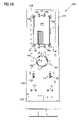
- FIG. 1is a front plan view of a fiber optic enclosure useable to implement various aspects of the present disclosure
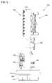
- FIG. 2is a bottom plan view of the fiber optic enclosure of FIG. 1 ;
- FIG. 3is a front perspective view of a fiber optic distribution assembly shown with the cover removed to provide access to inner components of the assembly and incorporating fiber optic cabling to illustrate optical signal routing;
- FIG. 4is a front perspective exploded view of the fiber optic distribution assembly of FIG. 3 , with cabling removed;
- FIG. 5is a front plan view of the fiber optic distribution assembly of FIG. 3 , with cabling removed;
- FIG. 6is a front plan view of the fiber optic distribution assembly of FIG. 3 , incorporating fiber optic cabling to illustrate optical signal routing;
- FIG. 7is a close-up perspective view of a portion of the fiber optic distribution assembly of FIG. 3 showing a plurality of adapter modules;
- FIG. 8is a rear perspective view of the fiber optic distribution assembly of FIG. 3 incorporating fiber optic cabling to illustrate optical signal routing;
- FIG. 9is a rear perspective exploded view of the fiber optic distribution assembly of FIG. 3 , with cabling removed;
- FIG. 10is a rear plan view of the fiber optic distribution assembly of FIG. 3 , with cabling removed;
- FIG. 11is a rear plan view of the fiber optic distribution assembly of FIG. 3 , incorporating fiber optic cabling to illustrate optical signal routing;
- FIG. 12is a side plan view of the fiber optic distribution assembly of FIG. 3 , with cabling removed;
- FIG. 13is a front perspective view of a second possible fiber optic distribution assembly shown with the cover removed to provide access to inner components of the assembly and incorporating fiber optic cabling to illustrate optical signal routing;
- FIG. 14is a rear perspective view of the fiber optic distribution assembly shown in FIG. 13 ;
- FIG. 15is a further rear perspective view of the fiber optic distribution assembly of FIG. 13 , with an adapter module in an extended position;
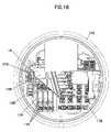
- FIG. 16is a top plan view of the fiber optic distribution assembly of FIG. 13 ;
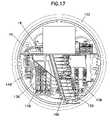
- FIG. 17is a further top plan view of the fiber optic distribution assembly of FIG. 13 , with an adapter module in an extended position.
- the present disclosureis generally related to a fiber optic distribution assembly, such as can be used in a variety of above ground and below ground outside plant (OSP) environments.
- OSPabove ground and below ground outside plant
- an enclosure 102configured for use in a fiber optic cable distribution assembly 100 is illustrated.
- the enclosure 102is useable in above ground and below ground applications and incorporating a number of fiber optic components, as described below.
- the enclosure 102is defined by a cover 104 and a base 106 , and includes an interior volume for containing fiber optic components.
- the enclosure 102is substantially cylindrical, and is constructed from watertight materials, such as metal or plastic.
- the enclosurehas a top 103 and a bottom 105 , defined by the cover 104 and base 106 , respectively.
- the cover 104 and base 106include mating abutting flanges 108 , 110 , respectively, and an O-ring (not shown).
- the abutting flanges 108 , 110are shaped for receiving a V-clamp (not shown) for forming a water-tight seal.
- any water that might be present in an underground vault housing the fiber optic distribution cable assembly 100does not reach the inner components of assembly 100 .
- the clamping arrangement between the cover 104 and base 106is described in further detail in U.S. patent application Ser. No. 11/137,855, the disclosure of which is incorporated by reference. It should be noted that a V-clamp/O-ring arrangement is one of the many possible sealing techniques that may be used to form a sealed enclosure 102 for distribution assembly 100 .
- a BSETM or BMTTM series thermoplastic sealed enclosuredistributed by Channell Commercial Corporation may be used for the enclosure 102 .
- the various internal fiber optic components within the enclosure 102fit within a cylindrical internal space having a diameter determined by the enclosure.
- the enclosureis pressurized, causing the air pressure in the interior of the enclosure 102 to exceed the atmospheric pressure outside the enclosure. Pressurization of the enclosure 102 helps further prevent moisture from penetrating the enclosure and reaching the fiber optic components in the interior of the assembly 100 .
- the base 106includes a plurality of openings 112 sized to accept fiber optic cables of various sizes and configurations.
- the openingsare punch-through type openings.
- Each openingis surrounded by a cylindrical extension 114 extending downwardly from the base 106 .
- the extensions 114provide a location at which a seal can be formed between the cable and the enclosure 102 .
- To insert a cable into the enclosure 102an opening of the correct diameter is selected, and the punch-through plate guarding the opening is removed. The cable can then be inserted into the selected opening 112 for connection to components internal to the enclosure 102 .
- Those openings which are not usedremain capped or sealed to prevent water from entering the enclosure when it is sealed.
- the enclosure 102may be mounted in a variety of locations, depending upon the routing requirements of a fiber optic network in which the assembly 100 is incorporated.
- the enclosurecan have a stand, pedestal or pole mount arrangement, or can also be installed in a rack or handhole location.
- the fiber optic distribution assembly 100is shown with the cover 104 removed to allow access to the components in the interior of the assembly.
- the fiber optic distribution assembly 100includes a mounting structure 116 .
- the mounting structure 116is generally planar, and includes a top 118 , a bottom end 120 , a front side 122 , a rear side 124 , a right side 126 and a left side 128 .
- the fiber optic cablesinclude an input cable 10 and an output cable 12 each carrying a plurality of optical signals, as described below.
- the input and output cables 10 , 12respectively, enter the base 106 of the enclosure 102 and central strength members of the cables affix to the rear side 124 of a mounting structure 116 via support clamps 130 .
- Fiber clamps 131also hold the jackets of the input cable 10 and output cable 12 in place, and ground the jackets of the fiber cables 10 , 12 to the mounting structure 116 .
- One or more fiber strands in the input cable 10are optionally spliced using a splice tray, described below, to secondary input cables 10 ′ then routed to the front side 122 of the mounting structure 116 through an opening 132 near the bottom end 120 .
- Fiber strands 11 from the input cable 10 which are not routed by the assembly 100are placed around the perimeter of the rear side 124 of the mounting structure 116 and to the output cable 12 .
- the mounting structure 116is configured to support a number of fiber optic components mounted to the front side 122 and rear side 124 .
- the front side 122 of the mounting structure 116shown in FIGS. 3-7 , includes a splitter housing 134 , an adapter assembly 136 , an excess connector storage structure 138 , and various radius limiters 140 and fan outs 142 .
- the rear side 124 of the mounting structure 116shown in FIGS. 8-11 , includes an optional splice tray 144 and various other cable support and routing features. Layout and operation of these components are described below.
- the fiber optic distribution assembly 100Adjacent the bottom end 120 of the front side 122 of the mounting structure 116 , the fiber optic distribution assembly 100 includes a splitter housing 134 , such as a splitter chassis or splitter bank.
- the splitter housing 134houses a plurality of splitter modules 145 that split the incoming optical signals carried through the input cable 10 (i.e., a feeder cable, an outside plant cable, or an OSP cable), routed into the enclosure 102 through the base 106 , into a plurality of secondary signals which can be distributed through the output cable 12 exiting through the base 106 to customer locations.
- the splitter housing 134accepts up to four splitter modules 145 . Different numbers of splitter modules are possible depending upon the size of the enclosure and the number of connections desired.
- Each splitter module 145includes a plurality of input connectors 146 that extend along the module.
- the input connectors 146preferably accept SC type connectors for optical signals.
- Splitter adapter assemblies 147are positioned and arranged at the inputs of one or more splitter modules 145 such that when an input cable is slidably inserted into the splitter housing 134 , input connectors 146 of the splitter modules 145 plug into the splitter adapter assemblies 147 . Dust plugs (not shown) are utilized when there is not a splitter module 145 connected to a splitter adapter assembly 147 .
- each signalis split into twenty four signals by internal splitter circuitry within the splitter module.
- This type of a splitter configurationis called a 1 ⁇ 24 splitter. It should be noted that other splitter configurations such as a 1 ⁇ 32 splitter, a 2 ⁇ 16 splitter, a 1 ⁇ 16 splitter, etc., could be used in other embodiments depending upon the desired service.
- Split signal cables (i.e., secondary cables) 14are then directed out of outputs 148 of splitter module 144 .
- the split signal cables 14are also preferably terminated with connectors.
- splitter modules 145may be added to the assembly 100 .
- the splitter modules 145can be added or removed from the splitter housing 134 without interrupting or disrupting activity of other splitter modules present in the housing.
- Each splitter module 145includes preconnectorized split signal cables, shown as secondary cables 14 , which can be stored in the excess connector storage structure 138 , described below, until use in the adapter assembly 136 .
- Splitter modules similar to those shown hereinare described in greater detail in commonly owned U.S. patent application Ser. Nos. 10/980,978, filed Nov. 3, 2004; 11/138,063, filed May 25, 2005; 11/138,889, filed May 25, 2005; and 11/354,297, filed Feb. 13, 2006, the entire disclosures of which are incorporated herein by reference.
- the adapter assembly 136resides at the top 118 of the front side 122 of the mounting structure 116 .
- the adapter assembly 136defines the connection routing from a service provider to one or more customers, and allows a service technician to conveniently activate and route fiber optic service to various pre-wired customer locations.
- the adapter assembly 136includes 16 horizontally arranged adapter modules 148 , each containing 6 adapters 150 for a total of 96 adapter connections. Different numbers of adapters 150 can be included in the adapter assembly 136 as well.
- the adapters 150have an input end and an output end, and each end is configured to accept a preconnectorized fiber optic cable.
- Each adapter module 148is mounted on an adapter module mount 152 that connect to the mounting structure 116 .
- Adapter module mounts 152provide structural support for and allow for slidability of adapter modules 148 .
- Adapter module mounts 152have extensions 154 for slidably receiving adapter modules 148 .
- Adapter modules 148are horizontally disposed and slidable between a retracted position and an extended position forwardly from the mounting structure 116 .
- the slidability of adapter modules 148facilitates access to densely populated adapters 150 and the corresponding cable connectors therein.
- Similar sliding adapter modulesare described in greater detail in commonly owned U.S. Pat. Nos. 5,497,444; 5,717,810; 6,591,051; and U.S. Patent Publication No. 2007/0025675, the disclosures of which are incorporated herein by reference.
- an excess connector storage structure 138resides on the front side 122 of the mounting structure 116 next to the splitter housing 134 , proximate the bottom end 120 .
- a number of the split signal cables 14may be directed to the excess connector storage structure 138 rather than the adapters 150 in the adapter assembly 136 , described above.
- the excess connector storage structure 138includes a bulkhead 156 that defines mounting slots 158 for mounting connector holders 159 .
- Each connector holder 159includes a plurality of openings for receiving and releasably holding fiber optic connector such as the connectors on the split signal cables 14 extending from the splitter modules 144 .
- the excess connector storage structure 134holds 40 connectors, with each of the mounting connector holders 159 holding eight connectors. In other embodiments, more or fewer connectors can be held in the storage structure 138 .
- the openings in connector holders 159may not provide a continuous optical path but rather house and protect a polished end face of an optical fiber within cable 14 . This protection may be provided in combination with an endcap (not shown), such as shown in commonly-owned U.S. patent application Ser. No. 10/610,325, filed on Jun. 30, 2003, the disclosure of which is incorporated herein by reference.
- a connector holder 159may enclose and protect the polished end face of the connector terminating cable without the need for a protective endcap. Excess connector storage structure 138 and connector holder 159 are described in greater detail in commonly-owned U.S. patent application Ser. No. 10/871,555, filed on Jun. 18, 2004, the disclosure of which is incorporated herein by reference.
- a radius limiter 140resides between the splitter housing 134 and the adapter assembly 136 , and routes the split signal cables 14 leading from the splitter housing 134 downwardly toward either the excess connector storage structure 138 or to one or more additional radius limiters 140 .
- the unused split signal cables 14route directly to the excess connector storage structure 138 .
- the cablesare routed to the adapter assembly 136 via additional radius limiters 140 which in turn route the cables upwardly within the assembly 100 to a plurality of fanouts 142 .
- the fanouts 142also provide radius limiting protection and also redirect the now-upwardly oriented split signal cables 14 horizontally into an unoccupied adapter 150 within the adapter assembly 136 .
- One or more cable clips 141may hold the cables in place along the radius limiters 140 .
- the fiber splice tray 144resides opposite the adapter assembly 136 , and houses up to four splice modules 160 .
- the output connectors of the adapter assembly 136connect to a second set of split signal cables 16 leading from the adapter assembly 136 which route through a slotted opening 161 along the edge of the mounting structure 116 , and optionally into one or more of the splice modules 160 in the fiber splice tray 144 .
- the splice modules 160receive optical cables from the adapter assembly 136 , and fuse optical fibers together for signal transmission.
- the input cable 10is spliced in one splice module 160 with a secondary input cable 10 ′ which leads through the opening 132 to the splitter modules 145 on the front side 122 of the mounting structure 116 .
- a second splice module 160fuses the cables 16 leading from the adapter assembly 136 on the front side 122 with optical fibers within an output cable 12 leading out from the enclosure 102 to a customer location.
- the splice tray 144 and splice modules 160are not included in the assembly 100 .
- the cables 16can be connected to the output cable 12 by a second set of adapters, or the output cable 12 can be connectorized and directly connected to the output connectors of the adapter assembly 134 .
- An optional excess cable storage structure 162mounts on the rear side 124 of the mounting structure 116 , directly below the fiber splice tray 144 .
- the excess cable storage structure 162is a spool structure which provides a cable slack storage arrangement for excess length of the optical fibers of the input cable 10 , output cable 12 or second split signal cables 16 .
- the excess cable storage structure 162also provides bend radius protection to the cables and routes the optical fibers of the input cable 10 and output cable 12 between the splice tray 144 and the bottom end of the assembly 100 , where the cables enter or exit the openings 112 in the base 106 .
- Cable clips 141may be located near the optional excess cable storage structure 162 to hold optical cables in place on the spool.
- Radius limiters 140positioned near inputs and outputs of the splice tray guide and protect optical fibers entering one or more of the splice modules 160 . Additional radius limiters 140 at each corner of the splice tray 144 guide the unrouted optical fiber strands 11 from the input cable 10 to the output cable 12 along the perimeter of the rear side 124 of the mounting structure 116 .
- FIGS. 13-17show a second possible fiber optic distribution assembly 200 with the cover removed to provide access to inner components of the assembly.
- the assembly 200can be environmentally protected using an enclosure such as disclosed in FIGS. 1-2 , above.
- the assembly 200includes a mounting structure 216 configured to support fiber optic components mounted thereon.
- the mounting structure 216includes a front side 222 and a rear side 224 .
- the front side 222 of the mounting structure 216includes a splitter housing 134 , an adapter assembly 136 , an excess connector storage structure 138 , and various radius limiters 140 and fan outs 142 .
- the rear side 224 of the mounting structure 216includes a cable support structure 266 having a plurality of cable tie-downs 267 , or an optional splice tray (not shown).
- the front and rear sidescan include additional cable holding equipment, as well as various other cable support and routing features. Operation of these components and routing of optical signals among the components is described above in conjunction with the assembly 100 .
- a pass through adapter module 148 ′attaches to the mounting structure 216 alongside the splitter housing 134 , as shown in FIG. 13 .
- Single fiber or multifiber cables routed to the pass through adapter module 148 ′route optical signal cables through the assembly 200 along the same path as the cables split via splitter modules 145 .
- a cable received by the assembly 200 as part of an input cable 10can be routed to the front side of the structure 216 and connected to either an adapter 150 in the pass through adapter module 148 ′ or to a splitter adapter assembly 147 at the input of one of the splitter modules 145 . Cables routed to the splitter adapter assembly 147 are split into 24 optical signals and routed as previously described.
- Cables routed to the pass through adapter module 148 ′are not split, and therefore connecting cables extend from the output of the adapter module 148 ′ to route the plurality of optical signals to the adapter assembly 136 for connection, via an adapter 150 in an adapter module 148 , to other cables leading out of the assembly 200 .
- an output cablecan connect directly to adapter module 148 ′, and not pass through the adapter assembly 136 .
- the mounting structure 216includes a plurality of cable routing slots 270 disposed along a top portion of one side of the structure, in the same location as the slotted opening 161 of the mounting structure 116 , above.
- the cable routing slots 270provide cable management and slack allowance for split signal cables 16 connected to the adapter modules, and are the method by which the split signal cables 16 leading from the adapter assembly 136 pass to the rear side of the mounting structure 216 , where they attach to the cable support structure 266 or optionally enter a splice tray and then route out of the assembly 200 .
- Each of the cable routing slots 270extends horizontally from the edge of the mounting structure toward an interior point proximate to the cable support structure 266 (or splice tray), at which each slot 270 terminates at a connector pass-through opening 271 .
- the slots 270are of a width to allow the split signal cables 16 to slide through, but are not sufficiently wide along the entire length to allow a connectorized end of a cable 16 to pass through the mounting structure 216 .
- the connector pass-through openings 271 located at the end of each slot 270have a larger diameter than the width of the slot, and are sufficiently large to allow the connectorized end of the split signal cables 16 to pass through the mounting structure 216 .
- a technicianpasses the preconnectorized output cable from the cable support structure 266 or a splice tray through the connector pass-through openings 271 to connect to adapters 150 in the adapter assembly 136 .
- the technicianwill slide one or more of the adapter modules 148 from its retracted position to an extended position, as illustrated in FIGS. 14-17 . Movement of the adapter, modules 148 between the retracted position and extended position causes the slackened split signal cables 16 connected to that module to be extended, resulting in the split signal cables 16 sliding along the slot.
- the plurality of slots 270corresponds to the number of adapter modules 148 in the adapter assembly 136 , such that each of the adapter modules 148 is associated with a corresponding slot 270 .
- Cable routing in the assembly 200corresponds to the routing described in the assembly 100 described above, but does not include routing through a splice tray.
- the input cable 10enters the enclosure 102 , and one or more fibers from that cable 10 ′ are passed to the front side 222 of the mounting structure 216 .
- the fibers 10 ′are connected to either one of the splitter modules 145 , or to the pass through adapter module 148 ′.
- cables 14are routed from the splitter module 145 or adapter module 148 ′ to the excess connector storage structure 138 or to the adapter modules 148 , which connect to signal cables 16 .
- the signal cables 16pass through slots 270 to connect to the output cable 12 , in this instance without first routing to a splice tray.
- fiber optic distribution assemblies 100 , 200can be positioned in any orientation.
Landscapes
- Physics & Mathematics (AREA)
- General Physics & Mathematics (AREA)
- Optics & Photonics (AREA)
- Mechanical Coupling Of Light Guides (AREA)
- Light Guides In General And Applications Therefor (AREA)
Abstract
Description
Claims (33)
Priority Applications (5)
| Application Number | Priority Date | Filing Date | Title |
|---|---|---|---|
| US11/725,139US7583885B2 (en) | 2006-11-28 | 2007-03-15 | Fiber distribution enclosure |
| PCT/US2007/083308WO2008067110A1 (en) | 2006-11-28 | 2007-11-01 | Fiber distribution enclosure |
| EP07863767AEP2089750A1 (en) | 2006-11-28 | 2007-11-01 | Fiber distribution enclosure |
| TW096143085ATW200838073A (en) | 2006-11-28 | 2007-11-14 | Fiber distribution enclosure |
| ARP070105240AAR063974A1 (en) | 2006-11-28 | 2007-11-27 | OPTICAL AND METHOD FIBER DISTRIBUTION AREA |
Applications Claiming Priority (2)
| Application Number | Priority Date | Filing Date | Title |
|---|---|---|---|
| US86175006P | 2006-11-28 | 2006-11-28 | |
| US11/725,139US7583885B2 (en) | 2006-11-28 | 2007-03-15 | Fiber distribution enclosure |
Publications (2)
| Publication Number | Publication Date |
|---|---|
| US20080124038A1 US20080124038A1 (en) | 2008-05-29 |
| US7583885B2true US7583885B2 (en) | 2009-09-01 |
Family
ID=39277310
Family Applications (1)
| Application Number | Title | Priority Date | Filing Date |
|---|---|---|---|
| US11/725,139ActiveUS7583885B2 (en) | 2006-11-28 | 2007-03-15 | Fiber distribution enclosure |
Country Status (5)
| Country | Link |
|---|---|
| US (1) | US7583885B2 (en) |
| EP (1) | EP2089750A1 (en) |
| AR (1) | AR063974A1 (en) |
| TW (1) | TW200838073A (en) |
| WO (1) | WO2008067110A1 (en) |
Cited By (14)
| Publication number | Priority date | Publication date | Assignee | Title |
|---|---|---|---|---|
| US20080203240A1 (en)* | 2007-01-19 | 2008-08-28 | Mark Smrha | Lateral storage spool for overhead cable pathway |
| US20090067803A1 (en)* | 2007-01-19 | 2009-03-12 | Adc Telecommunications, Inc. | Overhead cable termination arrangement |
| US20090245744A1 (en)* | 2007-03-09 | 2009-10-01 | Adc Telecommunications, Inc. | Wall mount distribution arrangement |
| US20110181158A1 (en)* | 2010-01-18 | 2011-07-28 | Adc Telecommunications, Inc. | Fiber distribution enclosure |
| US8186890B2 (en) | 1997-05-20 | 2012-05-29 | Adc Telecommunications, Inc. | Fiber connector and adapter |
| US8208781B1 (en) | 2009-12-03 | 2012-06-26 | Adtran, Inc. | Fiber optic connector panel |
| US9829665B1 (en) | 2017-04-27 | 2017-11-28 | Afl Telecommunications Llc | Fiber optic splice enclosures |
| US10048452B1 (en) | 2017-06-28 | 2018-08-14 | Sumitomo Electric Lightwave Corp. | System and method for joining and distributing a single optical fiber cable to multiple rack shelves |
| US10180553B2 (en)* | 2017-02-17 | 2019-01-15 | Corning Research & Development Corporation | Terminal assemblies, end cap assemblies, and fiber optic enclosures incorporating the same |
| US10261279B1 (en) | 2017-10-12 | 2019-04-16 | Sumitomo Electric Lightwave Corp. | System and method for distributing high fiber count optical cable to network racks |
| US10830975B2 (en)* | 2015-01-12 | 2020-11-10 | Afl Telecommunications Llc | Fiber optic terminal enclosure |
| US11150428B2 (en) | 2017-03-20 | 2021-10-19 | CommScope Connectivity Belgium BVBA | Telecommunications system and methods |
| US20240345354A1 (en)* | 2016-04-07 | 2024-10-17 | Commscope Technologies Llc | Telecommunications module and frame |
| US12276857B2 (en) | 2019-10-07 | 2025-04-15 | Commscope Technologies Llc | Fiber distribution hub including sealed splice module |
Families Citing this family (45)
| Publication number | Priority date | Publication date | Assignee | Title |
|---|---|---|---|---|
| US7916988B2 (en)* | 2006-12-22 | 2011-03-29 | Verizon Services Corp. | Optical splitter assembly |
| US7349616B1 (en) | 2007-01-12 | 2008-03-25 | Corning Cable Systems Llc | Fiber optic local convergence points for multiple dwelling units |
| EP2573602B1 (en) | 2007-09-06 | 2014-07-09 | Prysmian S.p.A. | Modular system and methods for connecting an external communication network to a user network of a building |
| CN102209921B (en)* | 2008-10-09 | 2015-11-25 | 康宁光缆系统有限公司 | There is the fibre-optic terminus supported from the adapter panel of the input and output optical fiber of optical splitters |
| MX2011008002A (en)* | 2009-01-28 | 2011-09-15 | Adc Telecommunications Inc | Fiber optic enclosure. |
| US20110013875A1 (en)* | 2009-07-16 | 2011-01-20 | Adc Telecommunications, Inc. | Fiber optic enclosure with adapter bulkhead positioned beneath pivotal splice tray |
| US8606067B2 (en)* | 2009-09-04 | 2013-12-10 | Adc Telecommunications, Inc. | Pedestal terminal with swing frame |
| WO2011076275A1 (en)* | 2009-12-23 | 2011-06-30 | Prysmian S.P.A. | Optical termination assembly |
| NZ605540A (en)* | 2010-07-02 | 2015-02-27 | Chih-Kuang Hsing | Optical cable connection box with auxiliary device for gap filling and waterproofing |
| WO2012054454A2 (en) | 2010-10-19 | 2012-04-26 | Corning Cable Systems Llc | Transition box for multiple dwelling unit fiber optic distribution network |
| US8861919B2 (en) | 2011-02-16 | 2014-10-14 | Tyco Electronics Corporation | Fiber optic closure |
| US9417418B2 (en) | 2011-09-12 | 2016-08-16 | Commscope Technologies Llc | Flexible lensed optical interconnect device for signal distribution |
| US9219546B2 (en) | 2011-12-12 | 2015-12-22 | Corning Optical Communications LLC | Extremely high frequency (EHF) distributed antenna systems, and related components and methods |
| US10110307B2 (en) | 2012-03-02 | 2018-10-23 | Corning Optical Communications LLC | Optical network units (ONUs) for high bandwidth connectivity, and related components and methods |
| US9791653B2 (en)* | 2012-04-03 | 2017-10-17 | CommScope Connectivity Belgium BVBA | Telecommunications enclosure organizer |
| NZ706687A (en) | 2012-09-28 | 2017-09-29 | Adc Telecommunications Inc | Fiber optic cassette |
| US9753229B2 (en) | 2012-09-28 | 2017-09-05 | Commscope Connectivity Uk Limited | Manufacture and testing of fiber optic cassette |
| US9223094B2 (en) | 2012-10-05 | 2015-12-29 | Tyco Electronics Nederland Bv | Flexible optical circuit, cassettes, and methods |
| ES1141660Y (en) | 2012-12-19 | 2015-10-14 | Tyco Electronics Raychem Bvba | Distribution device with incrementally added dividers |
| CN105074525A (en) | 2013-01-29 | 2015-11-18 | 泰科电子瑞侃有限公司 | Fiber Distribution System |
| EP2989496B1 (en) | 2013-04-24 | 2019-06-12 | CommScope Connectivity Belgium BVBA | Universal mounting mechanism for mounting a telecommunications chassis to a telecommunications fixture |
| AP2015008820A0 (en) | 2013-04-24 | 2015-10-31 | Adc Czech Republic Sro | Optical fiber distribution system |
| US10094985B2 (en)* | 2013-09-23 | 2018-10-09 | Commscope Connectivity Uk Limited | Cleaning pads for fiber optic connectors |
| AU2015276109B2 (en) | 2014-06-17 | 2020-11-19 | Adc Czech Republic, S.R.O. | Cable distribution system |
| US9641659B2 (en)* | 2014-12-12 | 2017-05-02 | Boyce Technologies Inc. | Access node and method |
| AU2016239875C1 (en)* | 2015-04-03 | 2021-06-24 | CommScope Connectivity Belgium BVBA | Telecommunications distribution elements |
| US10606009B2 (en) | 2015-12-01 | 2020-03-31 | CommScope Connectivity Belgium BVBA | Cable distribution system with fan out devices |
| EP3408701B1 (en) | 2016-01-28 | 2023-04-26 | CommScope Connectivity Belgium BVBA | Modular telecommunications enclosure |
| WO2018046677A1 (en) | 2016-09-08 | 2018-03-15 | CommScope Connectivity Belgium BVBA | Telecommunications distribution elements |
| CA2984824A1 (en)* | 2016-11-08 | 2018-05-08 | Ortronics, Inc. | Splice managers and related methods of use |
| US20190064463A1 (en)* | 2017-07-25 | 2019-02-28 | Ofs Fitel, Llc | In-line outdoor façade optical fiber distribution closure |
| US11409068B2 (en) | 2017-10-02 | 2022-08-09 | Commscope Technologies Llc | Fiber optic circuit and preparation method |
| US11852882B2 (en) | 2018-02-28 | 2023-12-26 | Commscope Technologies Llc | Packaging assembly for telecommunications equipment |
| US11635578B2 (en) | 2018-04-17 | 2023-04-25 | CommScope Connectivity Belgium BVBA | Telecommunications distribution elements |
| EP3845044B1 (en) | 2018-08-31 | 2023-02-15 | CommScope Connectivity Belgium BVBA | Frame assemblies for optical fiber distribution elements |
| EP3844546A1 (en) | 2018-08-31 | 2021-07-07 | CommScope Connectivity Belgium BVBA | Frame assemblies for optical fiber distribution elements |
| EP3844547A1 (en) | 2018-08-31 | 2021-07-07 | CommScope Connectivity Belgium BVBA | Frame assemblies for optical fiber distribution elements |
| PL3844973T3 (en) | 2018-08-31 | 2025-03-03 | CommScope Connectivity Belgium BVBA | Frame assemblies for optical fiber distribution elements |
| WO2020043914A1 (en) | 2018-08-31 | 2020-03-05 | CommScope Connectivity Belgium BVBA | Frame assemblies for optical fiber distribution elements |
| WO2020084012A1 (en) | 2018-10-23 | 2020-04-30 | CommScope Connectivity Belgium BVBA | Frame assemblies for optical fiber distribution elements |
| EP3914947A1 (en) | 2019-01-25 | 2021-12-01 | CommScope Connectivity Belgium BVBA | Frame assemblies for optical fiber distribution elements |
| US10585256B1 (en)* | 2019-03-29 | 2020-03-10 | Corning Research & Development Corporation | Terminal of an optical fiber network having a bypass module |
| WO2021148544A1 (en) | 2020-01-22 | 2021-07-29 | CommScope Connectivity Belgium BVBA | Cable termination units for optical fiber distribution elements |
| US12099246B2 (en) | 2020-01-24 | 2024-09-24 | CommScope Connectivity Belgium BVBA | Telecommunications distribution elements |
| US12339511B2 (en) | 2020-03-31 | 2025-06-24 | Commscope Technologies Llc | Fiber optic cable management systems and methods |
Citations (44)
| Publication number | Priority date | Publication date | Assignee | Title |
|---|---|---|---|---|
| US5497444A (en) | 1994-01-21 | 1996-03-05 | Adc Telecommunications, Inc. | High-density fiber distribution frame |
| US5734776A (en)* | 1996-08-28 | 1998-03-31 | Adc Telecommunications, Inc. | Outside plant cross-connect apparatus |
| US6330389B1 (en)* | 1999-11-18 | 2001-12-11 | Lucent Technologies, Inc. | System for organizing optical fibers |
| US6359228B1 (en) | 2000-01-31 | 2002-03-19 | Corning Cable Systems Llc | Splice closure |
| US6411767B1 (en) | 1999-08-24 | 2002-06-25 | Corning Cable Systems Llc | Optical fiber interconnection closures |
| US6483977B2 (en) | 2001-04-12 | 2002-11-19 | Corning Cable Systems Llc | Fiber management frame having movable work platform |
| US6496640B1 (en) | 1999-12-16 | 2002-12-17 | Corning Cable Systems Llc | Splice closure with removable and pivotable splice trays, and associated methods |
| US6539160B2 (en) | 2000-10-27 | 2003-03-25 | Corning Cable Systems Llc | Optical fiber splicing and connecting assembly with coupler cassette |
| US6542688B1 (en) | 2000-10-27 | 2003-04-01 | Corning Cable Systems Llc | Optical fiber splicing and connecting assembly |
| US6560394B1 (en) | 2000-11-17 | 2003-05-06 | Corning Cable Systems Llc | Fiber management frame for closure |
| US20030112964A1 (en) | 2001-12-17 | 2003-06-19 | Morgan Kevin L. | Re-enterable housing for xDSL/POTS splitter |
| US6591051B2 (en) | 2001-11-16 | 2003-07-08 | Adc Telecommunications, Inc. | Fiber termination block with angled slide |
| US6621975B2 (en)* | 2001-11-30 | 2003-09-16 | Corning Cable Systems Llc | Distribution terminal for network access point |
| US6654536B2 (en) | 2001-04-12 | 2003-11-25 | Corning Cable Systems Llc | Fiber management frame having connector platform |
| US20030231849A1 (en) | 2002-06-18 | 2003-12-18 | Diana Rodriguez | Closures and cassettes for housing bridge and/or transition optical fibers in dispersion-managed networks |
| US6766094B2 (en)* | 2002-06-28 | 2004-07-20 | Corning Cable Systems Llc | Aerial closure for local convergence point |
| US6778752B2 (en)* | 2002-05-31 | 2004-08-17 | Corning Cable Systems Llc | Below grade closure for local convergence point |
| US6792191B1 (en) | 2003-04-22 | 2004-09-14 | Corning Cable Systems Llc | Local convergence cabinet |
| US6798967B2 (en) | 2001-04-12 | 2004-09-28 | Corning Cable Systems Llc | Fiber management frame for securely retaining optical fiber connection trays |
| WO2004086112A1 (en) | 2003-03-20 | 2004-10-07 | Tyco Electronics Corporation | Optical fiber interconnect cabinet |
| US6856747B2 (en)* | 2001-05-25 | 2005-02-15 | Preformed Line Products Company | Fiber optic cable closure and assembly |
| US20050105873A1 (en) | 2003-11-17 | 2005-05-19 | Fiber Optic Network Solutions Corporation | Systems and methods for managing optical fibers and components within an enclosure in an optical communications networks |
| US20050207711A1 (en) | 2004-03-19 | 2005-09-22 | Vo Chanh C | Optical termination pedestal |
| US7013074B2 (en)* | 2004-02-06 | 2006-03-14 | Corning Cable Systems Llc | Optical connection closure having at least one connector port |
| US20060083475A1 (en)* | 2003-10-06 | 2006-04-20 | Christopher Grubish | Optical fiber splice case |
| US7038137B2 (en)* | 2003-06-18 | 2006-05-02 | Preformed Line Products Company | Fiber closure system |
| US20060093301A1 (en) | 2004-11-03 | 2006-05-04 | Zimmel Steven C | Fiber optic module and system including rear connectors |
| US20060193587A1 (en)* | 2005-02-25 | 2006-08-31 | Charles Industries, Ltd. | Fiber optic splice enclosure |
| US20060193588A1 (en)* | 2005-02-28 | 2006-08-31 | Mertesdorf Daniel R | Fiber access terminal |
| US20060263029A1 (en) | 2005-05-18 | 2006-11-23 | Mudd Ronald L | High density optical fiber distribution enclosure |
| US20060269206A1 (en) | 2005-05-25 | 2006-11-30 | Zimmel Steven C | Fiber optic adapter module |
| US20060269205A1 (en) | 2005-05-25 | 2006-11-30 | Zimmel Steven C | Fiber optic splitter module |
| US20060269204A1 (en) | 2005-05-25 | 2006-11-30 | Michael Barth | Outside plant fiber distribution enclosure with radial arrangement |
| US20070025675A1 (en) | 2005-07-27 | 2007-02-01 | Anne Kramer | Fiber optic adapter module |
| US20070031100A1 (en)* | 2005-08-04 | 2007-02-08 | Garcia Cesar G | Optical fiber distribution cabinet |
| US20070047894A1 (en) | 2005-08-29 | 2007-03-01 | Matt Holmberg | Outside plant enclosure with pivoting fiber trays |
| US7190874B1 (en)* | 2005-10-03 | 2007-03-13 | Adc Telecommunications, Inc. | Fiber demarcation box with cable management |
| US7194181B2 (en) | 2005-03-31 | 2007-03-20 | Adc Telecommunications, Inc. | Adapter block including connector storage |
| US7198409B2 (en) | 2003-06-30 | 2007-04-03 | Adc Telecommunications, Inc. | Fiber optic connector holder and method |
| US7218827B2 (en) | 2004-06-18 | 2007-05-15 | Adc Telecommunications, Inc. | Multi-position fiber optic connector holder and method |
| US7233731B2 (en) | 2003-07-02 | 2007-06-19 | Adc Telecommunications, Inc. | Telecommunications connection cabinet |
| US7308183B2 (en)* | 2006-01-04 | 2007-12-11 | Adc Telecommunications, Inc. | Fiber access terminal including moisture barrier plate |
| US7330628B1 (en)* | 2006-10-23 | 2008-02-12 | Adc Telecommunications, Inc. | Fiber access terminal including moisture barrier plate with punch out |
| US7418183B2 (en)* | 2006-02-08 | 2008-08-26 | Charles Industries, Ltd. | Fiber optic splice enclosure |
- 2007
- 2007-03-15USUS11/725,139patent/US7583885B2/enactiveActive
- 2007-11-01EPEP07863767Apatent/EP2089750A1/ennot_activeWithdrawn
- 2007-11-01WOPCT/US2007/083308patent/WO2008067110A1/enactiveApplication Filing
- 2007-11-14TWTW096143085Apatent/TW200838073A/enunknown
- 2007-11-27ARARP070105240Apatent/AR063974A1/enunknown
Patent Citations (51)
| Publication number | Priority date | Publication date | Assignee | Title |
|---|---|---|---|---|
| US5717810A (en) | 1994-01-21 | 1998-02-10 | Adc Telecommunications, Inc. | High-density fiber distribution frame |
| US5497444A (en) | 1994-01-21 | 1996-03-05 | Adc Telecommunications, Inc. | High-density fiber distribution frame |
| US5734776A (en)* | 1996-08-28 | 1998-03-31 | Adc Telecommunications, Inc. | Outside plant cross-connect apparatus |
| US6493501B2 (en) | 1999-08-24 | 2002-12-10 | Corning Cable Systems Llc | Optical fiber interconnection closures |
| US6411767B1 (en) | 1999-08-24 | 2002-06-25 | Corning Cable Systems Llc | Optical fiber interconnection closures |
| US6330389B1 (en)* | 1999-11-18 | 2001-12-11 | Lucent Technologies, Inc. | System for organizing optical fibers |
| US6496640B1 (en) | 1999-12-16 | 2002-12-17 | Corning Cable Systems Llc | Splice closure with removable and pivotable splice trays, and associated methods |
| US6359228B1 (en) | 2000-01-31 | 2002-03-19 | Corning Cable Systems Llc | Splice closure |
| US6539160B2 (en) | 2000-10-27 | 2003-03-25 | Corning Cable Systems Llc | Optical fiber splicing and connecting assembly with coupler cassette |
| US6542688B1 (en) | 2000-10-27 | 2003-04-01 | Corning Cable Systems Llc | Optical fiber splicing and connecting assembly |
| US6560394B1 (en) | 2000-11-17 | 2003-05-06 | Corning Cable Systems Llc | Fiber management frame for closure |
| US6483977B2 (en) | 2001-04-12 | 2002-11-19 | Corning Cable Systems Llc | Fiber management frame having movable work platform |
| US6798967B2 (en) | 2001-04-12 | 2004-09-28 | Corning Cable Systems Llc | Fiber management frame for securely retaining optical fiber connection trays |
| US6654536B2 (en) | 2001-04-12 | 2003-11-25 | Corning Cable Systems Llc | Fiber management frame having connector platform |
| US6856747B2 (en)* | 2001-05-25 | 2005-02-15 | Preformed Line Products Company | Fiber optic cable closure and assembly |
| US6591051B2 (en) | 2001-11-16 | 2003-07-08 | Adc Telecommunications, Inc. | Fiber termination block with angled slide |
| US6621975B2 (en)* | 2001-11-30 | 2003-09-16 | Corning Cable Systems Llc | Distribution terminal for network access point |
| US20030112964A1 (en) | 2001-12-17 | 2003-06-19 | Morgan Kevin L. | Re-enterable housing for xDSL/POTS splitter |
| US6778752B2 (en)* | 2002-05-31 | 2004-08-17 | Corning Cable Systems Llc | Below grade closure for local convergence point |
| US20030231849A1 (en) | 2002-06-18 | 2003-12-18 | Diana Rodriguez | Closures and cassettes for housing bridge and/or transition optical fibers in dispersion-managed networks |
| US6766094B2 (en)* | 2002-06-28 | 2004-07-20 | Corning Cable Systems Llc | Aerial closure for local convergence point |
| WO2004086112A1 (en) | 2003-03-20 | 2004-10-07 | Tyco Electronics Corporation | Optical fiber interconnect cabinet |
| US7142764B2 (en) | 2003-03-20 | 2006-11-28 | Tyco Electronics Corporation | Optical fiber interconnect cabinets, termination modules and fiber connectivity management for the same |
| US6792191B1 (en) | 2003-04-22 | 2004-09-14 | Corning Cable Systems Llc | Local convergence cabinet |
| US7038137B2 (en)* | 2003-06-18 | 2006-05-02 | Preformed Line Products Company | Fiber closure system |
| US7198409B2 (en) | 2003-06-30 | 2007-04-03 | Adc Telecommunications, Inc. | Fiber optic connector holder and method |
| US7233731B2 (en) | 2003-07-02 | 2007-06-19 | Adc Telecommunications, Inc. | Telecommunications connection cabinet |
| US20060083475A1 (en)* | 2003-10-06 | 2006-04-20 | Christopher Grubish | Optical fiber splice case |
| US20050129379A1 (en) | 2003-11-17 | 2005-06-16 | Fiber Optic Network Solutions Corporation | Systems and methods for optical fiber distribution and management |
| US20050105873A1 (en) | 2003-11-17 | 2005-05-19 | Fiber Optic Network Solutions Corporation | Systems and methods for managing optical fibers and components within an enclosure in an optical communications networks |
| US7013074B2 (en)* | 2004-02-06 | 2006-03-14 | Corning Cable Systems Llc | Optical connection closure having at least one connector port |
| US20050207711A1 (en) | 2004-03-19 | 2005-09-22 | Vo Chanh C | Optical termination pedestal |
| US7218827B2 (en) | 2004-06-18 | 2007-05-15 | Adc Telecommunications, Inc. | Multi-position fiber optic connector holder and method |
| US20060093301A1 (en) | 2004-11-03 | 2006-05-04 | Zimmel Steven C | Fiber optic module and system including rear connectors |
| US20060193587A1 (en)* | 2005-02-25 | 2006-08-31 | Charles Industries, Ltd. | Fiber optic splice enclosure |
| US20060193588A1 (en)* | 2005-02-28 | 2006-08-31 | Mertesdorf Daniel R | Fiber access terminal |
| US7194181B2 (en) | 2005-03-31 | 2007-03-20 | Adc Telecommunications, Inc. | Adapter block including connector storage |
| US20060263029A1 (en) | 2005-05-18 | 2006-11-23 | Mudd Ronald L | High density optical fiber distribution enclosure |
| US20060269206A1 (en) | 2005-05-25 | 2006-11-30 | Zimmel Steven C | Fiber optic adapter module |
| US20060269204A1 (en) | 2005-05-25 | 2006-11-30 | Michael Barth | Outside plant fiber distribution enclosure with radial arrangement |
| US20060269205A1 (en) | 2005-05-25 | 2006-11-30 | Zimmel Steven C | Fiber optic splitter module |
| US7260301B2 (en)* | 2005-05-25 | 2007-08-21 | Adc Telecommunications, Inc. | Outside plant fiber distribution enclosure with radial arrangement |
| US20070025675A1 (en) | 2005-07-27 | 2007-02-01 | Anne Kramer | Fiber optic adapter module |
| US20070031100A1 (en)* | 2005-08-04 | 2007-02-08 | Garcia Cesar G | Optical fiber distribution cabinet |
| US20070047894A1 (en) | 2005-08-29 | 2007-03-01 | Matt Holmberg | Outside plant enclosure with pivoting fiber trays |
| US7352945B2 (en)* | 2005-08-29 | 2008-04-01 | Adc Telecommunications, Inc. | Outside plant enclosure with pivoting fiber trays |
| US7190874B1 (en)* | 2005-10-03 | 2007-03-13 | Adc Telecommunications, Inc. | Fiber demarcation box with cable management |
| US7327926B2 (en)* | 2005-10-03 | 2008-02-05 | Adc Telecommunications, Inc. | Fiber demarcation box with cable management |
| US7308183B2 (en)* | 2006-01-04 | 2007-12-11 | Adc Telecommunications, Inc. | Fiber access terminal including moisture barrier plate |
| US7418183B2 (en)* | 2006-02-08 | 2008-08-26 | Charles Industries, Ltd. | Fiber optic splice enclosure |
| US7330628B1 (en)* | 2006-10-23 | 2008-02-12 | Adc Telecommunications, Inc. | Fiber access terminal including moisture barrier plate with punch out |
Non-Patent Citations (1)
| Title |
|---|
| U.S. Appl. No. 11/354,297, filed Feb. 13, 2006. |
Cited By (28)
| Publication number | Priority date | Publication date | Assignee | Title |
|---|---|---|---|---|
| US8186890B2 (en) | 1997-05-20 | 2012-05-29 | Adc Telecommunications, Inc. | Fiber connector and adapter |
| US9383524B2 (en) | 1997-05-20 | 2016-07-05 | Commscope Technologies Llc | Fiber connector and adapter |
| US8870466B2 (en) | 1997-05-20 | 2014-10-28 | Adc Telecommunications, Inc. | Fiber connector and adapter |
| US8070112B2 (en) | 2007-01-19 | 2011-12-06 | Adc Telecommunications, Inc. | Lateral storage spool for overhead cable pathway |
| US10585259B2 (en) | 2007-01-19 | 2020-03-10 | Commscope Technologies Llc | Overhead cable termination arrangement |
| US20110116758A1 (en)* | 2007-01-19 | 2011-05-19 | Adc Telecommunications, Inc. | Overhead cable termination arrangement |
| US7899299B2 (en)* | 2007-01-19 | 2011-03-01 | Adc Telecommunications, Inc. | Overhead cable termination arrangement |
| US20080203240A1 (en)* | 2007-01-19 | 2008-08-28 | Mark Smrha | Lateral storage spool for overhead cable pathway |
| US9632274B2 (en) | 2007-01-19 | 2017-04-25 | Commscope Technologies Llc | Overhead cable termination arrangement |
| US20090067803A1 (en)* | 2007-01-19 | 2009-03-12 | Adc Telecommunications, Inc. | Overhead cable termination arrangement |
| US8376288B2 (en) | 2007-01-19 | 2013-02-19 | Adc Telecommunications, Inc. | Lateral storage spool for overhead cable pathway |
| US8750670B2 (en)* | 2007-01-19 | 2014-06-10 | Adc Telecommunications, Inc. | Overhead cable termination arrangement |
| US20090245744A1 (en)* | 2007-03-09 | 2009-10-01 | Adc Telecommunications, Inc. | Wall mount distribution arrangement |
| US7831125B2 (en) | 2007-03-09 | 2010-11-09 | Adc Telecommunications, Inc. | Wall mount distribution arrangement |
| US8208781B1 (en) | 2009-12-03 | 2012-06-26 | Adtran, Inc. | Fiber optic connector panel |
| US20110181158A1 (en)* | 2010-01-18 | 2011-07-28 | Adc Telecommunications, Inc. | Fiber distribution enclosure |
| US8498510B2 (en)* | 2010-01-18 | 2013-07-30 | Adc Telecommunications, Inc. | Fiber distribution enclosure |
| US10830975B2 (en)* | 2015-01-12 | 2020-11-10 | Afl Telecommunications Llc | Fiber optic terminal enclosure |
| US12271047B2 (en)* | 2016-04-07 | 2025-04-08 | Commscope Technologies Llc | Telecommunications module and frame |
| US20240345354A1 (en)* | 2016-04-07 | 2024-10-17 | Commscope Technologies Llc | Telecommunications module and frame |
| US10180553B2 (en)* | 2017-02-17 | 2019-01-15 | Corning Research & Development Corporation | Terminal assemblies, end cap assemblies, and fiber optic enclosures incorporating the same |
| US11150428B2 (en) | 2017-03-20 | 2021-10-19 | CommScope Connectivity Belgium BVBA | Telecommunications system and methods |
| US9829665B1 (en) | 2017-04-27 | 2017-11-28 | Afl Telecommunications Llc | Fiber optic splice enclosures |
| US10241287B2 (en) | 2017-04-27 | 2019-03-26 | Afl Telecommunications Llc | Fiber optic splice enclosures |
| US10345538B2 (en) | 2017-06-28 | 2019-07-09 | Sumitomo Electric Lightwave Corp. | System and method for joining and distributing a single optical fiber cable to multiple rack shelves |
| US10048452B1 (en) | 2017-06-28 | 2018-08-14 | Sumitomo Electric Lightwave Corp. | System and method for joining and distributing a single optical fiber cable to multiple rack shelves |
| US10261279B1 (en) | 2017-10-12 | 2019-04-16 | Sumitomo Electric Lightwave Corp. | System and method for distributing high fiber count optical cable to network racks |
| US12276857B2 (en) | 2019-10-07 | 2025-04-15 | Commscope Technologies Llc | Fiber distribution hub including sealed splice module |
Also Published As
| Publication number | Publication date |
|---|---|
| AR063974A1 (en) | 2009-03-04 |
| EP2089750A1 (en) | 2009-08-19 |
| US20080124038A1 (en) | 2008-05-29 |
| WO2008067110A1 (en) | 2008-06-05 |
| TW200838073A (en) | 2008-09-16 |
Similar Documents
| Publication | Publication Date | Title |
|---|---|---|
| US7583885B2 (en) | Fiber distribution enclosure | |
| US12306450B2 (en) | Fiber distribution hub | |
| US10782497B2 (en) | Telecommunications connection cabinet | |
| US7190874B1 (en) | Fiber demarcation box with cable management | |
| US6160946A (en) | Outside plant fiber distribution apparatus and method | |
| US8606067B2 (en) | Pedestal terminal with swing frame | |
| WO2011050185A2 (en) | Fiber distribution hub and cable for use therewith | |
| US8380034B2 (en) | Splice holder device using downwardly-extending arms | |
| US8498510B2 (en) | Fiber distribution enclosure | |
| US11150428B2 (en) | Telecommunications system and methods | |
| US20250306323A1 (en) | Fiber distribution hub including sealed splice module |
Legal Events
| Date | Code | Title | Description |
|---|---|---|---|
| AS | Assignment | Owner name:ADC TELECOMMUNICATIONS, INC., MINNESOTA Free format text:ASSIGNMENT OF ASSIGNORS INTEREST;ASSIGNORS:KOWALCZYK, SCOTT C.;KAML, JONATHAN R.;SMITH, TREVOR D.;REEL/FRAME:019582/0158;SIGNING DATES FROM 20070508 TO 20070514 | |
| STCF | Information on status: patent grant | Free format text:PATENTED CASE | |
| FPAY | Fee payment | Year of fee payment:4 | |
| AS | Assignment | Owner name:TYCO ELECTRONICS SERVICES GMBH, SWITZERLAND Free format text:ASSIGNMENT OF ASSIGNORS INTEREST;ASSIGNOR:ADC TELECOMMUNICATIONS, INC.;REEL/FRAME:036060/0174 Effective date:20110930 | |
| AS | Assignment | Owner name:COMMSCOPE EMEA LIMITED, IRELAND Free format text:ASSIGNMENT OF ASSIGNORS INTEREST;ASSIGNOR:TYCO ELECTRONICS SERVICES GMBH;REEL/FRAME:036956/0001 Effective date:20150828 | |
| AS | Assignment | Owner name:COMMSCOPE TECHNOLOGIES LLC, NORTH CAROLINA Free format text:ASSIGNMENT OF ASSIGNORS INTEREST;ASSIGNOR:COMMSCOPE EMEA LIMITED;REEL/FRAME:037012/0001 Effective date:20150828 | |
| AS | Assignment | Owner name:JPMORGAN CHASE BANK, N.A., AS COLLATERAL AGENT, ILLINOIS Free format text:PATENT SECURITY AGREEMENT (TERM);ASSIGNOR:COMMSCOPE TECHNOLOGIES LLC;REEL/FRAME:037513/0709 Effective date:20151220 Owner name:JPMORGAN CHASE BANK, N.A., AS COLLATERAL AGENT, ILLINOIS Free format text:PATENT SECURITY AGREEMENT (ABL);ASSIGNOR:COMMSCOPE TECHNOLOGIES LLC;REEL/FRAME:037514/0196 Effective date:20151220 Owner name:JPMORGAN CHASE BANK, N.A., AS COLLATERAL AGENT, IL Free format text:PATENT SECURITY AGREEMENT (TERM);ASSIGNOR:COMMSCOPE TECHNOLOGIES LLC;REEL/FRAME:037513/0709 Effective date:20151220 Owner name:JPMORGAN CHASE BANK, N.A., AS COLLATERAL AGENT, IL Free format text:PATENT SECURITY AGREEMENT (ABL);ASSIGNOR:COMMSCOPE TECHNOLOGIES LLC;REEL/FRAME:037514/0196 Effective date:20151220 | |
| FPAY | Fee payment | Year of fee payment:8 | |
| AS | Assignment | Owner name:COMMSCOPE TECHNOLOGIES LLC, NORTH CAROLINA Free format text:RELEASE BY SECURED PARTY;ASSIGNOR:JPMORGAN CHASE BANK, N.A.;REEL/FRAME:048840/0001 Effective date:20190404 Owner name:REDWOOD SYSTEMS, INC., NORTH CAROLINA Free format text:RELEASE BY SECURED PARTY;ASSIGNOR:JPMORGAN CHASE BANK, N.A.;REEL/FRAME:048840/0001 Effective date:20190404 Owner name:ALLEN TELECOM LLC, ILLINOIS Free format text:RELEASE BY SECURED PARTY;ASSIGNOR:JPMORGAN CHASE BANK, N.A.;REEL/FRAME:048840/0001 Effective date:20190404 Owner name:COMMSCOPE, INC. OF NORTH CAROLINA, NORTH CAROLINA Free format text:RELEASE BY SECURED PARTY;ASSIGNOR:JPMORGAN CHASE BANK, N.A.;REEL/FRAME:048840/0001 Effective date:20190404 Owner name:ANDREW LLC, NORTH CAROLINA Free format text:RELEASE BY SECURED PARTY;ASSIGNOR:JPMORGAN CHASE BANK, N.A.;REEL/FRAME:048840/0001 Effective date:20190404 Owner name:COMMSCOPE TECHNOLOGIES LLC, NORTH CAROLINA Free format text:RELEASE BY SECURED PARTY;ASSIGNOR:JPMORGAN CHASE BANK, N.A.;REEL/FRAME:049260/0001 Effective date:20190404 Owner name:ANDREW LLC, NORTH CAROLINA Free format text:RELEASE BY SECURED PARTY;ASSIGNOR:JPMORGAN CHASE BANK, N.A.;REEL/FRAME:049260/0001 Effective date:20190404 Owner name:REDWOOD SYSTEMS, INC., NORTH CAROLINA Free format text:RELEASE BY SECURED PARTY;ASSIGNOR:JPMORGAN CHASE BANK, N.A.;REEL/FRAME:049260/0001 Effective date:20190404 Owner name:COMMSCOPE, INC. OF NORTH CAROLINA, NORTH CAROLINA Free format text:RELEASE BY SECURED PARTY;ASSIGNOR:JPMORGAN CHASE BANK, N.A.;REEL/FRAME:049260/0001 Effective date:20190404 Owner name:ALLEN TELECOM LLC, ILLINOIS Free format text:RELEASE BY SECURED PARTY;ASSIGNOR:JPMORGAN CHASE BANK, N.A.;REEL/FRAME:049260/0001 Effective date:20190404 | |
| AS | Assignment | Owner name:JPMORGAN CHASE BANK, N.A., NEW YORK Free format text:TERM LOAN SECURITY AGREEMENT;ASSIGNORS:COMMSCOPE, INC. OF NORTH CAROLINA;COMMSCOPE TECHNOLOGIES LLC;ARRIS ENTERPRISES LLC;AND OTHERS;REEL/FRAME:049905/0504 Effective date:20190404 Owner name:JPMORGAN CHASE BANK, N.A., NEW YORK Free format text:ABL SECURITY AGREEMENT;ASSIGNORS:COMMSCOPE, INC. OF NORTH CAROLINA;COMMSCOPE TECHNOLOGIES LLC;ARRIS ENTERPRISES LLC;AND OTHERS;REEL/FRAME:049892/0396 Effective date:20190404 Owner name:WILMINGTON TRUST, NATIONAL ASSOCIATION, AS COLLATE Free format text:PATENT SECURITY AGREEMENT;ASSIGNOR:COMMSCOPE TECHNOLOGIES LLC;REEL/FRAME:049892/0051 Effective date:20190404 Owner name:WILMINGTON TRUST, NATIONAL ASSOCIATION, AS COLLATERAL AGENT, CONNECTICUT Free format text:PATENT SECURITY AGREEMENT;ASSIGNOR:COMMSCOPE TECHNOLOGIES LLC;REEL/FRAME:049892/0051 Effective date:20190404 | |
| FEPP | Fee payment procedure | Free format text:MAINTENANCE FEE REMINDER MAILED (ORIGINAL EVENT CODE: REM.); ENTITY STATUS OF PATENT OWNER: LARGE ENTITY | |
| FEPP | Fee payment procedure | Free format text:11.5 YR SURCHARGE- LATE PMT W/IN 6 MO, LARGE ENTITY (ORIGINAL EVENT CODE: M1556); ENTITY STATUS OF PATENT OWNER: LARGE ENTITY | |
| MAFP | Maintenance fee payment | Free format text:PAYMENT OF MAINTENANCE FEE, 12TH YEAR, LARGE ENTITY (ORIGINAL EVENT CODE: M1553); ENTITY STATUS OF PATENT OWNER: LARGE ENTITY Year of fee payment:12 | |
| AS | Assignment | Owner name:WILMINGTON TRUST, DELAWARE Free format text:SECURITY INTEREST;ASSIGNORS:ARRIS SOLUTIONS, INC.;ARRIS ENTERPRISES LLC;COMMSCOPE TECHNOLOGIES LLC;AND OTHERS;REEL/FRAME:060752/0001 Effective date:20211115 | |
| AS | Assignment | Owner name:COMMSCOPE, INC. OF NORTH CAROLINA, NORTH CAROLINA Free format text:PARTIAL RELEASE OF ABL SECURITY INTEREST;ASSIGNOR:JPMORGAN CHASE BANK, N.A.;REEL/FRAME:060649/0305 Effective date:20220712 Owner name:ARRIS ENTERPRISES LLC, NORTH CAROLINA Free format text:PARTIAL RELEASE OF ABL SECURITY INTEREST;ASSIGNOR:JPMORGAN CHASE BANK, N.A.;REEL/FRAME:060649/0305 Effective date:20220712 Owner name:COMMSCOPE TECHNOLOGIES LLC, NORTH CAROLINA Free format text:PARTIAL RELEASE OF ABL SECURITY INTEREST;ASSIGNOR:JPMORGAN CHASE BANK, N.A.;REEL/FRAME:060649/0305 Effective date:20220712 Owner name:COMMSCOPE, INC. OF NORTH CAROLINA, NORTH CAROLINA Free format text:PARTIAL RELEASE OF TERM LOAN SECURITY INTEREST;ASSIGNOR:JPMORGAN CHASE BANK, N.A.;REEL/FRAME:060649/0286 Effective date:20220712 Owner name:ARRIS ENTERPRISES LLC, NORTH CAROLINA Free format text:PARTIAL RELEASE OF TERM LOAN SECURITY INTEREST;ASSIGNOR:JPMORGAN CHASE BANK, N.A.;REEL/FRAME:060649/0286 Effective date:20220712 Owner name:COMMSCOPE TECHNOLOGIES LLC, NORTH CAROLINA Free format text:PARTIAL RELEASE OF TERM LOAN SECURITY INTEREST;ASSIGNOR:JPMORGAN CHASE BANK, N.A.;REEL/FRAME:060649/0286 Effective date:20220712 Owner name:BISON PATENT LICENSING, LLC, GEORGIA Free format text:ASSIGNMENT OF ASSIGNORS INTEREST;ASSIGNOR:COMMSCOPE TECHNOLOGIES LLC;REEL/FRAME:060641/0312 Effective date:20220628 | |
| AS | Assignment | Owner name:COMMSCOPE, INC. OF NORTH CAROLINA, NORTH CAROLINA Free format text:PARTIAL TERMINATION AND RELEASE OF SECURITY INTEREST IN PATENTS;ASSIGNOR:WILMINGTON TRUST, NATIONAL ASSOCIATION, AS COLLATERAL AGENT;REEL/FRAME:060671/0324 Effective date:20220711 Owner name:ARRIS ENTERPRISES LLC, PENNSYLVANIA Free format text:PARTIAL TERMINATION AND RELEASE OF SECURITY INTEREST IN PATENTS;ASSIGNOR:WILMINGTON TRUST, NATIONAL ASSOCIATION, AS COLLATERAL AGENT;REEL/FRAME:060671/0324 Effective date:20220711 Owner name:COMMSCOPE TECHNOLOGIES LLC, NORTH CAROLINA Free format text:PARTIAL TERMINATION AND RELEASE OF SECURITY INTEREST IN PATENTS;ASSIGNOR:WILMINGTON TRUST, NATIONAL ASSOCIATION, AS COLLATERAL AGENT;REEL/FRAME:060671/0324 Effective date:20220711 | |
| AS | Assignment | Owner name:ARRIS ENTERPRISES LLC, GEORGIA Free format text:RELEASE BY SECURED PARTY;ASSIGNOR:WILMINGTON TRUST, NATIONAL ASSOCIATION;REEL/FRAME:063270/0220 Effective date:20221116 Owner name:COMMSCOPE, INC. OF NORTH CAROLINA, NORTH CAROLINA Free format text:RELEASE BY SECURED PARTY;ASSIGNOR:WILMINGTON TRUST, NATIONAL ASSOCIATION;REEL/FRAME:063270/0220 Effective date:20221116 Owner name:COMMSCOPE TECHNOLOGIES LLC, NORTH CAROLINA Free format text:RELEASE BY SECURED PARTY;ASSIGNOR:WILMINGTON TRUST, NATIONAL ASSOCIATION;REEL/FRAME:063270/0220 Effective date:20221116 | |
| AS | Assignment | Owner name:ARRIS ENTERPRISES LLC, GEORGIA Free format text:PARTIAL TERMINATION AND RELEASE OF SECURITY INTEREST IN PATENTS RECORDED AT R/F 060752/0001;ASSIGNOR:WILMINGTON TRUST;REEL/FRAME:063322/0209 Effective date:20221116 Owner name:COMMSCOPE, INC. OF NORTH CAROLINA, NORTH CAROLINA Free format text:PARTIAL TERMINATION AND RELEASE OF SECURITY INTEREST IN PATENTS RECORDED AT R/F 060752/0001;ASSIGNOR:WILMINGTON TRUST;REEL/FRAME:063322/0209 Effective date:20221116 Owner name:COMMSCOPE TECHNOLOGIES LLC, NORTH CAROLINA Free format text:PARTIAL TERMINATION AND RELEASE OF SECURITY INTEREST IN PATENTS RECORDED AT R/F 060752/0001;ASSIGNOR:WILMINGTON TRUST;REEL/FRAME:063322/0209 Effective date:20221116 | |
| AS | Assignment | Owner name:RUCKUS WIRELESS, LLC (F/K/A RUCKUS WIRELESS, INC.), NORTH CAROLINA Free format text:RELEASE OF SECURITY INTEREST AT REEL/FRAME 049905/0504;ASSIGNOR:JPMORGAN CHASE BANK, N.A., AS COLLATERAL AGENT;REEL/FRAME:071477/0255 Effective date:20241217 Owner name:COMMSCOPE TECHNOLOGIES LLC, NORTH CAROLINA Free format text:RELEASE OF SECURITY INTEREST AT REEL/FRAME 049905/0504;ASSIGNOR:JPMORGAN CHASE BANK, N.A., AS COLLATERAL AGENT;REEL/FRAME:071477/0255 Effective date:20241217 Owner name:COMMSCOPE, INC. OF NORTH CAROLINA, NORTH CAROLINA Free format text:RELEASE OF SECURITY INTEREST AT REEL/FRAME 049905/0504;ASSIGNOR:JPMORGAN CHASE BANK, N.A., AS COLLATERAL AGENT;REEL/FRAME:071477/0255 Effective date:20241217 Owner name:ARRIS SOLUTIONS, INC., NORTH CAROLINA Free format text:RELEASE OF SECURITY INTEREST AT REEL/FRAME 049905/0504;ASSIGNOR:JPMORGAN CHASE BANK, N.A., AS COLLATERAL AGENT;REEL/FRAME:071477/0255 Effective date:20241217 Owner name:ARRIS TECHNOLOGY, INC., NORTH CAROLINA Free format text:RELEASE OF SECURITY INTEREST AT REEL/FRAME 049905/0504;ASSIGNOR:JPMORGAN CHASE BANK, N.A., AS COLLATERAL AGENT;REEL/FRAME:071477/0255 Effective date:20241217 Owner name:ARRIS ENTERPRISES LLC (F/K/A ARRIS ENTERPRISES, INC.), NORTH CAROLINA Free format text:RELEASE OF SECURITY INTEREST AT REEL/FRAME 049905/0504;ASSIGNOR:JPMORGAN CHASE BANK, N.A., AS COLLATERAL AGENT;REEL/FRAME:071477/0255 Effective date:20241217 |