US7583883B2 - Fiber optic connector holder - Google Patents
Fiber optic connector holderDownload PDFInfo
- Publication number
- US7583883B2 US7583883B2US11/190,511US19051105AUS7583883B2US 7583883 B2US7583883 B2US 7583883B2US 19051105 AUS19051105 AUS 19051105AUS 7583883 B2US7583883 B2US 7583883B2
- Authority
- US
- United States
- Prior art keywords
- fiber optic
- optic connector
- housing
- connector holder
- cavity
- Prior art date
- Legal status (The legal status is an assumption and is not a legal conclusion. Google has not performed a legal analysis and makes no representation as to the accuracy of the status listed.)
- Expired - Fee Related, expires
Links
Images


Classifications
- G—PHYSICS
- G02—OPTICS
- G02B—OPTICAL ELEMENTS, SYSTEMS OR APPARATUS
- G02B6/00—Light guides; Structural details of arrangements comprising light guides and other optical elements, e.g. couplings
- G02B6/24—Coupling light guides
- G02B6/36—Mechanical coupling means
- G02B6/38—Mechanical coupling means having fibre to fibre mating means
- G02B6/3807—Dismountable connectors, i.e. comprising plugs
- G02B6/3833—Details of mounting fibres in ferrules; Assembly methods; Manufacture
- G02B6/3847—Details of mounting fibres in ferrules; Assembly methods; Manufacture with means preventing fibre end damage, e.g. recessed fibre surfaces
- G02B6/3849—Details of mounting fibres in ferrules; Assembly methods; Manufacture with means preventing fibre end damage, e.g. recessed fibre surfaces using mechanical protective elements, e.g. caps, hoods, sealing membranes
- G—PHYSICS
- G02—OPTICS
- G02B—OPTICAL ELEMENTS, SYSTEMS OR APPARATUS
- G02B6/00—Light guides; Structural details of arrangements comprising light guides and other optical elements, e.g. couplings
- G02B6/24—Coupling light guides
- G02B6/36—Mechanical coupling means
- G02B6/38—Mechanical coupling means having fibre to fibre mating means
- G02B6/3807—Dismountable connectors, i.e. comprising plugs
- G02B6/3873—Connectors using guide surfaces for aligning ferrule ends, e.g. tubes, sleeves, V-grooves, rods, pins, balls
- G02B6/3874—Connectors using guide surfaces for aligning ferrule ends, e.g. tubes, sleeves, V-grooves, rods, pins, balls using tubes, sleeves to align ferrules
- G02B6/3878—Connectors using guide surfaces for aligning ferrule ends, e.g. tubes, sleeves, V-grooves, rods, pins, balls using tubes, sleeves to align ferrules comprising a plurality of ferrules, branching and break-out means
- G02B6/3879—Linking of individual connector plugs to an overconnector, e.g. using clamps, clips, common housings comprising several individual connector plugs
- G—PHYSICS
- G02—OPTICS
- G02B—OPTICAL ELEMENTS, SYSTEMS OR APPARATUS
- G02B6/00—Light guides; Structural details of arrangements comprising light guides and other optical elements, e.g. couplings
- G02B6/24—Coupling light guides
- G02B6/36—Mechanical coupling means
- G02B6/38—Mechanical coupling means having fibre to fibre mating means
- G02B6/3807—Dismountable connectors, i.e. comprising plugs
- G02B6/389—Dismountable connectors, i.e. comprising plugs characterised by the method of fastening connecting plugs and sockets, e.g. screw- or nut-lock, snap-in, bayonet type
- G02B6/3893—Push-pull type, e.g. snap-in, push-on
- G—PHYSICS
- G02—OPTICS
- G02B—OPTICAL ELEMENTS, SYSTEMS OR APPARATUS
- G02B6/00—Light guides; Structural details of arrangements comprising light guides and other optical elements, e.g. couplings
- G02B6/44—Mechanical structures for providing tensile strength and external protection for fibres, e.g. optical transmission cables
- G02B6/4439—Auxiliary devices
- G02B6/444—Systems or boxes with surplus lengths
- G02B6/44528—Patch-cords; Connector arrangements in the system or in the box
Definitions
- the present applicationrelates to a fiber optic connector holder for fiber optic telecommunications installations.
- telecommunications equipmentto support the current and potential future needs of a particular group of customers may make it desirable to install more capacity than the current customer base alone may dictate. Excess capacity may be installed to permit the easy addition of new circuits for new or existing customers. A telecommunications connection cabinet with such excess capacity may be pre-configured at a fabrication facility and installed in the field to include more circuits than are necessary to provide service to the existing customers. Prior to the linkage of these surplus or future expansion circuits to customers, it is desirable to provide for storage, organization and protection of the patch cords or other connection cables within the cabinet.
- connection cablesmight include fiber optic patch cords terminated with fiber optic connectors.
- Fiber optic connectorsinclude a polished end face, typically held by a ferrule, which permits positioning of the optical fiber held by the connector to receive and transmit signals another optical fiber or optical light source. It is desirable to keep these polished end faces as free of contaminants as possible to improve the transmission of light to and from the optical fiber held by the connector. Such contaminants which might adversely impact the transmission of light to and from the optical fiber include but are not limited to dust and finger prints.
- Dust capsmay be provided for connectors to protect the polished end face of the optical fiber.
- the connectoris not capable of being received in known optical fiber adapters, such as those described in U.S. Pat. No. 5,317,663, and U.S. Pat. No. 6,347,888.
- a connectormay be inserted into one of these known adapters for storage or pre-wiring of a cross-connection point, an interconnection point or some other type telecommunications switching or connection equipment with the dust cap removed.
- the adaptersmight provide some protection from contaminants to a single connector inserted into an adapter, these adapters are not as effective as a dust cap in protecting the polished end face.
- Fiber optic connector holderswere disclosed in commonly-owned U.S. patent application Ser. No. 10/613,764, filed Jul. 2, 2003 and entitled Fiber to the Premise Cabinet. The disclosure of this application is incorporated herein by reference.
- the present inventionrelates generally to fiber optic connector holders. More specifically, the present invention relates to a fiber optic connector holder including a housing with at least one cavity for receiving a fiber optic connector with a dust cap in place about a terminal end of the connector.
- the housingmay be integrally molded with retaining structures for releasably engaging the fiber optic connector and releasable catches for mounting the housing at a mount location. The presence of a fiber optic connector within a cavity of the housing may prevent the removal of the housing from a mounting location.
- FIG. 1is a perspective view of a connector holder assembly according to the present invention.
- FIG. 2is a second perspective view of the connector holder assembly of FIG. 1 .
- FIG. 3is a side view of the connector holder assembly of FIG. 1 .
- FIG. 4is a side cross-sectional, partially exploded view of the connector holder assembly of FIG. 1 .
- FIG. 5is a perspective view of a connector holder of FIG. 1 , with a pair of fiber optic cables and connectors.
- FIG. 6is a second perspective view of the connector holder of FIG. 5 .
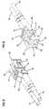
- FIG. 7is a first side view of the connector holder of FIG. 5 .
- FIG. 8is a second side view of the connector holder of FIG. 5 .
- FIG. 9is a side cross-sectional view of the connector holder of FIG. 5 .
- FIG. 10is a perspective view of the connector holder of FIG. 5 , with the cables and connectors removed.
- FIG. 11is a second perspective view of the connector holder of FIG. 10 .
- FIG. 12is an end view of an alternative embodiment of a connector holder according to the present invention.
- FIG. 13is a first side view of the connector holder of FIG. 12 .
- FIG. 14is a second side view of the connector holder of FIG. 12 .
- FIG. 15is a third side view of the connector holder of FIG. 12 .
- FIG. 16is a fourth side view of the connector holder of FIG. 12 .
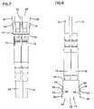
- FIG. 17is a side cross-sectional view of the connector holder of FIG. 10 .
- FIG. 18is a side cross-sectional view of the connector holder of FIG. 17 , with mounting tabs deflected inward for insertion at a mounting location.
- a connector holder assembly or sliding adapter module 10includes a housing 12 with a plurality of connector holders 14 mounted to housing 12 . Inserted within each connector holder 12 are a pair of fiber optic cables 16 , each including a connector 18 terminating the cable and a dust cap 20 mounted about a terminal end of the cable. Housing 12 includes a pair of opposing side walls 22 within each of which is formed a sliding groove 24 . As shown in U.S. Pat. No. 6,591,051, issued Jul. 8, 2003, the disclosure of which is incorporated herein by reference, such grooves 24 may engage side guides for slidably mounting connector holder assembly 10 to a telecommunications device.
- housing 12At the top of housing 12 is mounted a pivoting handle 26 to lift connector holder assembly 10 within the side guides and initiate and permit sliding movement of connector holder assembly 10 .
- a slide handle or clip 28At the bottom of housing 12 is a slide handle or clip 28 which may operate to retain connector holder assembly 10 within the side guides in a retracted or an extended position.
- connectors 18are received within a pair of cavities 30 within connector holder 14 .
- Connectors 18are engaged and releasably held within cavities 30 in a manner similar to the manner a known fiber optic adapter would engage connector 18 .
- connector holder 14permits the insertion of connector 18 with dust cap 20 in place about a terminal end of cable 16 , and further only permits insertion of a single connector 18 within cavity 30 .
- Known fiber optic adaptersare configured to receive and optically connect two connectors 18 and cannot receive a connector 18 with a dust cap 20 in place, as shown.
- Housing 12includes a plurality of mounting locations 32 for receiving and mounting connector holders 14 .
- connector holder 14includes a deflectable or movable mounting tab 34 and an opposing fixed mounting tab 36 on opposite sides of the connector holder.
- Movable tab 34deflects inward into cavity 30 to permit passage of connector holder 14 between a pair of opposing sides walls 38 defining an opening 40 at one of the mounting locations 32 .
- movable tabs 34spring back into their original undeflected position. Side walls 38 are then trapped between tabs 34 and 36 to hold connector holder 14 at mounting location 32 .
- mounting locations 32may also be populated with fiber optic adapters to used in the optical connection of two optical fiber cables 16 and connectors 18 .
- Such adaptersare well known in the telecommunications industry.
- housing 12is configured to provide a temporary holding location for fibers within a telecommunication chassis, module, rack, bulkhead, or other telecommunications device or installation.
- the temporary holding locationpermits storage of fiber 16 and connector 18 with protective dust cap 20 in place.
- connector 18can be removed from connector holder 14 , dust cap 20 removed from about the terminal end of cable 16 and cable 16 can be directed to the location where the connection is desired.
- the connector holder 14may be removed from housing 12 and either discarded or saved for future use.
- a compatible form factor fiber optic adaptermay be placed at mounting the now vacant mounting location 32 .
- housing 12is generally angled from perpendicular to an axis of insertion A of connectors 18 into connector holders 14 . While housing 12 is shown with two offset pairs of mounting locations 32 , with each opening 40 of the pair generally aligned with each other, it is anticipated that all four mounting locations 32 may be offset from each other. Such a continual offset arrangement of connector holders 14 might generally follow the angle of housing 12 . As shown in the referenced patents, housing 12 may also be configured with all the connectors holders in a line generally perpendicular to axis of insertion A.
- connector holders 14there are four connector holders 14 providing eight cavities 30 for receiving connectors 18 .
- Other numbers of connector holdersmay be provided and housing 12 extended or otherwise altered as necessary to accommodate more or fewer numbers of connector holders.
- Housing 12may also be adapted to mount connector holders of difference sizes or configurations.
- connector holder 14includes a housing 42 with a first end 44 and a second end 46 .
- Connector 18is inserted within cavity 30 through first end 44 and dust cap 20 mounted about the terminal end of cable 16 extends within cavity 30 to a position adjacent second end 46 .
- Each connector 18includes a releasable catch 19 .
- each cavity 30is an inner surface 48 of an outer side 50 , in which are located tabs 34 and 36 . As shown in FIG. 9 , when connector 18 is positioned within cavity 30 , connector 18 sits in close proximity to inner surface 48 of the corresponding side 50 . With one of the connectors 18 in place within cavity 30 , movable tab 34 cannot be deflected inward.
- each tab 34includes a ramp 34 angled toward first end 44 and a catch 54 .
- Catch 54is opposed by a catch 56 defined by fixed tab 36 .
- side walls 38 of opening 40are engaged to secure connector holder 14 to mounting location 32 .
- housing 42includes an opening 60 in each side 50 .
- a flexible arm 62is attached to side 50 at a proximal end 64 and extends to a distal end 66 within opening 60 .
- Movable tab 34is mounted adjacent distal end 66 and deflection of flexible arm 62 into cavity 30 beyond inner surface 48 permits positioning of connector holder 14 at mounting location 32 .
- Each cavity 30may also include structures 68 which engage releasable catch 19 of connector 18 to releasably secure connector 18 to connector holder 14 . While connectors 18 are shown as LC format connectors and connector holder 14 is configured to releasable engage connectors of this format, it is anticipated that other brands, styles or formats of connectors and corresponding mating structures may be used on housing 42 within the scope of the present disclosure.
- FIGS. 12 to 16show a second embodiment of a connector holder 114 with a housing 142 .
- Connector holder 114 and housing 142are configured similarly to connector holder 14 and housing 42 , with similar elements labeled with the same numbers.
- housing 42 and 142each include a transverse bulkhead 74 adjacent second end 46 and a transverse bulkhead 76 adjacent first end 44 .
- An open top 78 to cavity 30is defined between bulkheads 74 and 76 .
- the open top of cavity 30is provided to permit easier molding of housings 42 and 142 , so that each of the housings may be integral one-piece moldings including both connector engaging structures 68 and mounting tabs 34 and 36 .
- Bulkheads 74 and 76provide lateral strength to housings 42 and 142 and permit the remainder of cavities 30 to have an open top.
- Existing adapters and connector holdersmay have either connector engagement structures or mounting tabs provided in separate parts of molding which are assembled to form the adapter or connector holder.
- a longitudinal bulkhead 80which extends from a bottom 82 of housings 42 and 142 to at least transverse bulkheads 74 and 76 .
- FIGS. 17 and 18The extent of deflection required to position or remove connector holder 14 at mounting location 32 is shown in FIGS. 17 and 18 .
- arm 62in an undeflected position, arm 62 is generally in line with side wall 50 so that an inner surface 72 of arm 62 is generally in line with inner surface 48 .
- a connector 18can be positioned or removed from cavity 30 without any interference.
- Catches 54 and 56are facing each other and in position to capture sides 38 of opening 40 .
- movable tabs 34are depressed inward, deflecting arms 62 about proximal end 64 so that inner surface 72 of arm 62 is positioned inwardly from inner surface 48 of wall 50 into cavity 30 . Such deflection would not be possible with a connector 18 within cavity 30 . With movable tab 34 depressed inwardly enough so that an outermost extension 70 generally aligned with wall 50 , side 38 of opening 40 can be removed from or placed between catches 54 and 56 . Arms 62 are preferably made of a resilient deformable material that will return to the undeflected location shown in FIG. 17 after being depressed to the deflected location shown in FIG. 18 .
- a mounting location for connector holder 14may be defined in a variety of locations, wherever temporary storage of a connector with a protective dust cap in place may be desired.
- the configuration of connector holder 14 (and 114 )provides security against accidental removal from a mounting opening when connectors are positioned within cavities 30 , so that equipment with such connector holders may provide control of preinstalled cables in telecommunications equipment during transport, handling, installation, or environmental disturbances.
- connector holders and mounting locations according to the present disclosuremay be incorporated into bulkheads which are part of telecommunications equipment, such as that described in U.S. Pat. No. 6,556,763, issued Apr. 29, 2003, the disclosure of which is incorporated herein by reference. It is also anticipated that connector holders and mounting locations according to the present invention may be incorporated into drawers which are part of telecommunications equipment, such as that described in U.S. Pat. No. 6,504,988, issued Jan. 7, 2003, and in commonly-owned U.S. patent application Ser. No. 09/900,465, filed Jul. 6, 2001, the disclosures of which are incorporated herein by reference.
Landscapes
- Physics & Mathematics (AREA)
- General Physics & Mathematics (AREA)
- Optics & Photonics (AREA)
- Mechanical Coupling Of Light Guides (AREA)
- Connector Housings Or Holding Contact Members (AREA)
- Light Guides In General And Applications Therefor (AREA)
Abstract
Description
Claims (20)
Priority Applications (14)
| Application Number | Priority Date | Filing Date | Title |
|---|---|---|---|
| US11/190,511US7583883B2 (en) | 2005-07-26 | 2005-07-26 | Fiber optic connector holder |
| AU2006276114AAU2006276114B2 (en) | 2005-07-26 | 2006-07-20 | Fiber optic connector holder |
| AT06788020TATE422062T1 (en) | 2005-07-26 | 2006-07-20 | FIBER OPTICAL CONNECTOR HOLDER |
| KR1020087004432AKR20080033447A (en) | 2005-07-26 | 2006-07-20 | Fiber optic connector holder |
| PCT/US2006/028243WO2007015949A2 (en) | 2005-07-26 | 2006-07-20 | Fiber optic connector holder |
| EP06788020AEP1913430B1 (en) | 2005-07-26 | 2006-07-20 | Fiber optic connector holder |
| CN2006800270663ACN101228467B (en) | 2005-07-26 | 2006-07-20 | Optical fiber connector holder |
| JP2008523982AJP2009503582A (en) | 2005-07-26 | 2006-07-20 | Fiber optic connector holder |
| DK06788020TDK1913430T3 (en) | 2005-07-26 | 2006-07-20 | Fiber optic connector holder |
| MX2008000832AMX2008000832A (en) | 2005-07-26 | 2006-07-20 | Fiber optic connector holder. |
| DE602006005056TDE602006005056D1 (en) | 2005-07-26 | 2006-07-20 | FIBER OPTIC CONNECTOR HOLDER |
| ES06788020TES2317577T3 (en) | 2005-07-26 | 2006-07-20 | CARRIER FOR OPTICAL FIBER CONNECTORS. |
| US12/507,292US7945137B2 (en) | 2005-07-26 | 2009-07-22 | Fiber optic connector holder |
| US13/079,245US8391664B2 (en) | 2005-07-26 | 2011-04-04 | Fiber optic connector holder |
Applications Claiming Priority (1)
| Application Number | Priority Date | Filing Date | Title |
|---|---|---|---|
| US11/190,511US7583883B2 (en) | 2005-07-26 | 2005-07-26 | Fiber optic connector holder |
Related Child Applications (1)
| Application Number | Title | Priority Date | Filing Date |
|---|---|---|---|
| US12/507,292ContinuationUS7945137B2 (en) | 2005-07-26 | 2009-07-22 | Fiber optic connector holder |
Publications (2)
| Publication Number | Publication Date |
|---|---|
| US20070025674A1 US20070025674A1 (en) | 2007-02-01 |
| US7583883B2true US7583883B2 (en) | 2009-09-01 |
Family
ID=37398903
Family Applications (3)
| Application Number | Title | Priority Date | Filing Date |
|---|---|---|---|
| US11/190,511Expired - Fee RelatedUS7583883B2 (en) | 2005-07-26 | 2005-07-26 | Fiber optic connector holder |
| US12/507,292Expired - Fee RelatedUS7945137B2 (en) | 2005-07-26 | 2009-07-22 | Fiber optic connector holder |
| US13/079,245Expired - Fee RelatedUS8391664B2 (en) | 2005-07-26 | 2011-04-04 | Fiber optic connector holder |
Family Applications After (2)
| Application Number | Title | Priority Date | Filing Date |
|---|---|---|---|
| US12/507,292Expired - Fee RelatedUS7945137B2 (en) | 2005-07-26 | 2009-07-22 | Fiber optic connector holder |
| US13/079,245Expired - Fee RelatedUS8391664B2 (en) | 2005-07-26 | 2011-04-04 | Fiber optic connector holder |
Country Status (12)
| Country | Link |
|---|---|
| US (3) | US7583883B2 (en) |
| EP (1) | EP1913430B1 (en) |
| JP (1) | JP2009503582A (en) |
| KR (1) | KR20080033447A (en) |
| CN (1) | CN101228467B (en) |
| AT (1) | ATE422062T1 (en) |
| AU (1) | AU2006276114B2 (en) |
| DE (1) | DE602006005056D1 (en) |
| DK (1) | DK1913430T3 (en) |
| ES (1) | ES2317577T3 (en) |
| MX (1) | MX2008000832A (en) |
| WO (1) | WO2007015949A2 (en) |
Cited By (13)
| Publication number | Priority date | Publication date | Assignee | Title |
|---|---|---|---|---|
| US20090285541A1 (en)* | 2005-07-26 | 2009-11-19 | Adc Telecommunications, Inc. | Fiber optic connector holder |
| US20100310226A1 (en)* | 2009-06-03 | 2010-12-09 | Emerson Network Power, Energy Systems, North America, Inc. | Dust Caps for Fiber Optic Connectors |
| US20110013876A1 (en)* | 2009-07-17 | 2011-01-20 | Adc Telecommunications, Inc. | Fiber Optic Dust Cap and Connector for Terminating Multi-Fiber Optical Cables |
| US20110019962A1 (en)* | 2008-11-07 | 2011-01-27 | Childers Darrell R | Removable Sleeve for Fiber Optic Connectors for High Density Applications |
| US20110058775A1 (en)* | 2009-06-03 | 2011-03-10 | Emerson Network Power, Energy Systems, North America, Inc. | Dust Caps for Fiber Optic Connectors |
| US20110116748A1 (en)* | 2009-10-16 | 2011-05-19 | Adc Telecommunications, Inc. | Managed connectivity in fiber optic systems and methods thereof |
| US20110188813A1 (en)* | 2010-02-04 | 2011-08-04 | Thomas Marcouiller | Fiber Optic Dust Cap and Connector for Terminating Multi-Fiber Optical Cables |
| US8382382B2 (en) | 2008-08-27 | 2013-02-26 | Adc Telecommunications, Inc. | Fiber optic adapter with integrally molded ferrule alignment structure |
| US9014527B2 (en) | 2011-04-25 | 2015-04-21 | Adc Telecommunication, Inc. | Rack and chassis for fiber optic sliding adapter modules |
| US9146362B2 (en) | 2012-09-21 | 2015-09-29 | Adc Telecommunications, Inc. | Insertion and removal tool for a fiber optic ferrule alignment sleeve |
| US10302874B2 (en) | 2015-05-15 | 2019-05-28 | Commscope Telecommunications (Shanghai) Co., Ltd. | Alignment sleeve assembly and fiber optic adapter |
| US10598883B1 (en)* | 2017-12-15 | 2020-03-24 | Afl Ig Llc | Lanyard organizing tool for cable assembly |
| US12164153B2 (en) | 2019-01-09 | 2024-12-10 | Commscope Technologies Llc | Fiber optic adapter with integrally molded structures |
Families Citing this family (30)
| Publication number | Priority date | Publication date | Assignee | Title |
|---|---|---|---|---|
| US7167628B2 (en)* | 2004-12-13 | 2007-01-23 | Adc Telecommunications, Inc. | Service blocker device and method |
| US7349619B2 (en)* | 2005-05-25 | 2008-03-25 | Adc Telecommunications, Inc. | Fiber service blocker |
| US7734138B2 (en)* | 2007-05-30 | 2010-06-08 | Corning Cable Systems Llc | Fiber optic connector holders |
| US11294136B2 (en) | 2008-08-29 | 2022-04-05 | Corning Optical Communications LLC | High density and bandwidth fiber optic apparatuses and related equipment and methods |
| US8452148B2 (en) | 2008-08-29 | 2013-05-28 | Corning Cable Systems Llc | Independently translatable modules and fiber optic equipment trays in fiber optic equipment |
| US8184938B2 (en) | 2008-08-29 | 2012-05-22 | Corning Cable Systems Llc | Rear-installable fiber optic modules and equipment |
| US8538226B2 (en) | 2009-05-21 | 2013-09-17 | Corning Cable Systems Llc | Fiber optic equipment guides and rails configured with stopping position(s), and related equipment and methods |
| EP2443497B1 (en) | 2009-06-19 | 2020-03-04 | Corning Cable Systems LLC | High density and bandwidth fiber optic apparatus |
| JP5144623B2 (en) | 2009-10-28 | 2013-02-13 | Seiオプティフロンティア株式会社 | Optical connector assembly method |
| US8821030B2 (en)* | 2010-01-29 | 2014-09-02 | Afl Telecommunications Llc | High fiber count package foam insert |
| US9632270B2 (en) | 2010-04-30 | 2017-04-25 | Corning Optical Communications LLC | Fiber optic housings configured for tool-less assembly, and related components and methods |
| US9720195B2 (en) | 2010-04-30 | 2017-08-01 | Corning Optical Communications LLC | Apparatuses and related components and methods for attachment and release of fiber optic housings to and from an equipment rack |
| US9377597B2 (en)* | 2010-06-02 | 2016-06-28 | Commscope Technologies Llc | Aggregator for a switch rack system |
| WO2012106510A2 (en) | 2011-02-02 | 2012-08-09 | Corning Cable Systems Llc | Dense fiber optic connector assemblies and related connectors and cables suitable for establishing optical connections for optical backplanes in equipment racks |
| US9606303B2 (en)* | 2011-03-01 | 2017-03-28 | Us Conec, Ltd. | Grouping device for high density connector arrangements |
| NL1039467C2 (en)* | 2012-03-14 | 2013-09-18 | Conxys Technologies Internat B V | PANEL. |
| CN104823090B (en)* | 2012-11-30 | 2017-04-05 | 泰科电子公司 | Fiber optic connectors with field-installable outer connector housings |
| TWI451146B (en)* | 2013-02-23 | 2014-09-01 | Ezontek Technologies Co Ltd | Optical fiber adapter |
| CN104849816B (en) | 2014-02-14 | 2017-01-11 | 泰科电子(上海)有限公司 | Optical fiber connector and assembly method therefor |
| CN104849815B (en) | 2014-02-14 | 2017-01-18 | 泰科电子(上海)有限公司 | Optical fiber connector and assembly method therefor |
| CN105445862B (en) | 2014-07-09 | 2018-01-19 | 泰科电子(上海)有限公司 | The joints of optical fibre and its on-site assembly method |
| DE102014011611B4 (en) | 2014-08-01 | 2018-12-20 | Dürr Somac GmbH | Device for filling air conditioning systems (MAC) with a refrigerant in the vehicle final assembly |
| US9885845B2 (en)* | 2015-01-15 | 2018-02-06 | Commscope, Inc. Of North Carolina | Module and assembly for fiber optic interconnections |
| US10620385B2 (en) | 2015-11-30 | 2020-04-14 | Commscope Technologies Llc | Fiber optic connector and assembly thereof |
| US10641970B2 (en) | 2015-12-16 | 2020-05-05 | Commscope Technologies Llc | Field installed fiber optic connector |
| CN110998398B (en)* | 2017-06-28 | 2022-09-06 | 康宁研究与开发公司 | Fiber extender port, assembly and method of making same |
| EP3673308B1 (en) | 2017-08-23 | 2024-04-03 | Commscope Technologies LLC | Drop terminal |
| US11953750B2 (en) | 2020-04-30 | 2024-04-09 | Commscope Technologies Llc | Interlocking fiber optic connector holder |
| US20250028127A1 (en) | 2023-07-23 | 2025-01-23 | Sterlite Technologies Limited | Tool to Remove Dust Cap of Fiber Connector |
| EP4556975A1 (en)* | 2023-11-16 | 2025-05-21 | Corning Research And Development Corporation | Fiber optic cable management apparatus and terminal |
Citations (13)
| Publication number | Priority date | Publication date | Assignee | Title |
|---|---|---|---|---|
| EP0597501A1 (en) | 1992-11-13 | 1994-05-18 | International Business Machines Corporation | Fiber optic connector housing |
| US5317663A (en) | 1993-05-20 | 1994-05-31 | Adc Telecommunications, Inc. | One-piece SC adapter |
| US5647043A (en)* | 1995-10-12 | 1997-07-08 | Lucent Technologies, Inc. | Unipartite jack receptacle |
| JP2001188134A (en) | 1999-12-28 | 2001-07-10 | Sanwa Denki Kogyo Co Ltd | Panel installation fixture for optical adaptor |
| US6347888B1 (en) | 1998-11-23 | 2002-02-19 | Adc Telecommunications, Inc. | Fiber optic adapter, including hybrid connector system |
| US6409392B1 (en)* | 1999-10-19 | 2002-06-25 | Fitel Usa Corp. | Duplex clip for clipping two optical fiber simplex connectors together to form a duplex connector |
| US20030223703A1 (en) | 1999-12-07 | 2003-12-04 | Wenzong Chen | Self-contained fiber optic connector module |
| US20050002633A1 (en) | 2003-07-02 | 2005-01-06 | Solheid James J. | Telecommunications connection cabinet |
| JP2005345589A (en) | 2004-06-01 | 2005-12-15 | Yazaki Corp | Optical adapter removal jig |
| US6983095B2 (en) | 2003-11-17 | 2006-01-03 | Fiber Optic Network Solutions Corporation | Systems and methods for managing optical fibers and components within an enclosure in an optical communications network |
| US7198409B2 (en) | 2003-06-30 | 2007-04-03 | Adc Telecommunications, Inc. | Fiber optic connector holder and method |
| US7218827B2 (en) | 2004-06-18 | 2007-05-15 | Adc Telecommunications, Inc. | Multi-position fiber optic connector holder and method |
| US20080008436A1 (en) | 2003-11-17 | 2008-01-10 | Fiber Optics Network Solutions Corp. | Hinged parking in fiber distribution hubs |
Family Cites Families (7)
| Publication number | Priority date | Publication date | Assignee | Title |
|---|---|---|---|---|
| US6364537B1 (en)* | 2000-02-08 | 2002-04-02 | The Siemon Company | Dual polarity fiber optic adapter |
| EP1233437A3 (en)* | 2001-02-16 | 2002-11-06 | Tyco Electronics AMP GmbH | Plug-in module, carrier plate and relay arrangement |
| US7203317B2 (en)* | 2001-10-31 | 2007-04-10 | Hewlett-Packard Development Company, L.P. | System for enabling lazy-revocation through recursive key generation |
| US6591051B2 (en) | 2001-11-16 | 2003-07-08 | Adc Telecommunications, Inc. | Fiber termination block with angled slide |
| CN2554640Y (en)* | 2002-06-12 | 2003-06-04 | 富士康(昆山)电脑接插件有限公司 | Joints of optical fibre |
| US7527509B1 (en)* | 2005-06-21 | 2009-05-05 | Ideal Industries, Inc. | Electrical disconnect with push-in connectors |
| US7583883B2 (en)* | 2005-07-26 | 2009-09-01 | Adc Telecommunications, Inc. | Fiber optic connector holder |
- 2005
- 2005-07-26USUS11/190,511patent/US7583883B2/ennot_activeExpired - Fee Related
- 2006
- 2006-07-20ESES06788020Tpatent/ES2317577T3/enactiveActive
- 2006-07-20CNCN2006800270663Apatent/CN101228467B/ennot_activeExpired - Fee Related
- 2006-07-20WOPCT/US2006/028243patent/WO2007015949A2/enactiveApplication Filing
- 2006-07-20DEDE602006005056Tpatent/DE602006005056D1/enactiveActive
- 2006-07-20EPEP06788020Apatent/EP1913430B1/ennot_activeNot-in-force
- 2006-07-20ATAT06788020Tpatent/ATE422062T1/ennot_activeIP Right Cessation
- 2006-07-20JPJP2008523982Apatent/JP2009503582A/enactivePending
- 2006-07-20DKDK06788020Tpatent/DK1913430T3/enactive
- 2006-07-20KRKR1020087004432Apatent/KR20080033447A/ennot_activeCeased
- 2006-07-20MXMX2008000832Apatent/MX2008000832A/enactiveIP Right Grant
- 2006-07-20AUAU2006276114Apatent/AU2006276114B2/ennot_activeCeased
- 2009
- 2009-07-22USUS12/507,292patent/US7945137B2/ennot_activeExpired - Fee Related
- 2011
- 2011-04-04USUS13/079,245patent/US8391664B2/ennot_activeExpired - Fee Related
Patent Citations (27)
| Publication number | Priority date | Publication date | Assignee | Title |
|---|---|---|---|---|
| EP0597501A1 (en) | 1992-11-13 | 1994-05-18 | International Business Machines Corporation | Fiber optic connector housing |
| US5317663A (en) | 1993-05-20 | 1994-05-31 | Adc Telecommunications, Inc. | One-piece SC adapter |
| US5647043A (en)* | 1995-10-12 | 1997-07-08 | Lucent Technologies, Inc. | Unipartite jack receptacle |
| US6347888B1 (en) | 1998-11-23 | 2002-02-19 | Adc Telecommunications, Inc. | Fiber optic adapter, including hybrid connector system |
| US6409392B1 (en)* | 1999-10-19 | 2002-06-25 | Fitel Usa Corp. | Duplex clip for clipping two optical fiber simplex connectors together to form a duplex connector |
| US20030223703A1 (en) | 1999-12-07 | 2003-12-04 | Wenzong Chen | Self-contained fiber optic connector module |
| JP2001188134A (en) | 1999-12-28 | 2001-07-10 | Sanwa Denki Kogyo Co Ltd | Panel installation fixture for optical adaptor |
| US7407330B2 (en) | 2003-06-30 | 2008-08-05 | Adc Telecommunications, Inc. | Fiber optic connector holder and method |
| US7198409B2 (en) | 2003-06-30 | 2007-04-03 | Adc Telecommunications, Inc. | Fiber optic connector holder and method |
| US20050002633A1 (en) | 2003-07-02 | 2005-01-06 | Solheid James J. | Telecommunications connection cabinet |
| US20080075411A1 (en) | 2003-07-02 | 2008-03-27 | Adc Telecommunications, Inc. | Telecommunications connection cabinet |
| US7233731B2 (en) | 2003-07-02 | 2007-06-19 | Adc Telecommunications, Inc. | Telecommunications connection cabinet |
| US7146089B2 (en) | 2003-11-17 | 2006-12-05 | Fiber Optic Network Solutions Corporation | Systems and methods for fiber distribution hub administration |
| US6983095B2 (en) | 2003-11-17 | 2006-01-03 | Fiber Optic Network Solutions Corporation | Systems and methods for managing optical fibers and components within an enclosure in an optical communications network |
| US7200317B2 (en) | 2003-11-17 | 2007-04-03 | Fiber Optic Network Solutions Corporation | Systems and methods for optical fiber distribution and management |
| US7103255B2 (en) | 2003-11-17 | 2006-09-05 | Fiber Optic Networks Solutions Corporation | Optical splitter module |
| US7171102B2 (en) | 2003-11-17 | 2007-01-30 | Fiber Optic Network Solutions Corporation | Optical communication signal distribution enclosure |
| US7088899B2 (en) | 2003-11-17 | 2006-08-08 | Fiber Optic Networks Solutions Corporation | Configuring pigtails in a fiber distribution hub |
| US20080008436A1 (en) | 2003-11-17 | 2008-01-10 | Fiber Optics Network Solutions Corp. | Hinged parking in fiber distribution hubs |
| US20080013910A1 (en) | 2003-11-17 | 2008-01-17 | Fiber Optics Network Solutions Corp. | Hinged parking in fiber distribution hubs |
| US7400816B2 (en) | 2003-11-17 | 2008-07-15 | Fiber Optics Network Solutions Corp. | Telecommunications apparatus for distributing optical communications signals |
| US7369741B2 (en) | 2003-11-17 | 2008-05-06 | Fiber Optics Network Solutions Corp. | Storage adapter with dust cap posts |
| JP2005345589A (en) | 2004-06-01 | 2005-12-15 | Yazaki Corp | Optical adapter removal jig |
| US7218827B2 (en) | 2004-06-18 | 2007-05-15 | Adc Telecommunications, Inc. | Multi-position fiber optic connector holder and method |
| US20080025684A1 (en) | 2004-06-18 | 2008-01-31 | Adc Telecommunications, Inc. | Fiber Optic Splitter |
| US20080019655A1 (en) | 2004-06-18 | 2008-01-24 | Adc Telecommunications, Inc. | Fiber Optic Splitter |
| US7277620B2 (en) | 2004-06-18 | 2007-10-02 | Adc Telecommunications, Inc. | Fiber optic splitter |
Non-Patent Citations (3)
| Title |
|---|
| 24 photos of LambdaUnite(R) Blank Card; "LambdaUnite(R) MultiService Switch (MSS)" brochure (2003); and "Lucent's LambdaUnite(R) Busts Out" official release (Jan. 29, 2002). |
| U.S. Appl. No. 12/185,504 and Drawings, Filed Aug. 4, 2008 and Preliminary Amendment Filed Sep. 4, 2008. |
| U.S. Appl. No. 12/194,328 and Drawings, Filed Aug. 19, 2008. |
Cited By (36)
| Publication number | Priority date | Publication date | Assignee | Title |
|---|---|---|---|---|
| US7945137B2 (en)* | 2005-07-26 | 2011-05-17 | Adc Telecommunications, Inc. | Fiber optic connector holder |
| US20090285541A1 (en)* | 2005-07-26 | 2009-11-19 | Adc Telecommunications, Inc. | Fiber optic connector holder |
| US8845205B2 (en) | 2008-08-27 | 2014-09-30 | Adc Telecommunications, Inc. | Fiber optic adapter with integrally molded ferrule alignment structure |
| US9354402B2 (en) | 2008-08-27 | 2016-05-31 | Commscope Technologies Llc | Fiber optic adapter with integrally molded ferrule alignment structure |
| US9778422B2 (en) | 2008-08-27 | 2017-10-03 | Commscope Technologies Llc | Fiber optic adapter with integrally molded ferrule alignment structure |
| US10197741B2 (en) | 2008-08-27 | 2019-02-05 | Commscope Technologies Llc | Fiber optic adapter with integrally molded ferrule alignment structure |
| US8992095B2 (en) | 2008-08-27 | 2015-03-31 | Adc Telecommunications, Inc. | Fiber optic adapter with integrally molded ferrule alignment structure |
| US12001061B2 (en) | 2008-08-27 | 2024-06-04 | Commscope Technologies Llc | Fiber optic adapter with integrally molded ferrule alignment structure |
| US11567267B2 (en) | 2008-08-27 | 2023-01-31 | Commscope Technologies Llc | Fiber optic adapter with integrally molded ferrule alignment structure |
| US10795090B2 (en) | 2008-08-27 | 2020-10-06 | Commscope Technologies Llc | Fiber optic adapter with integrally molded ferrule alignment structure |
| US11262507B2 (en) | 2008-08-27 | 2022-03-01 | Commscope Technologies Llc | Fiber optic adapter with integrally molded ferrule alignment structure |
| US8382382B2 (en) | 2008-08-27 | 2013-02-26 | Adc Telecommunications, Inc. | Fiber optic adapter with integrally molded ferrule alignment structure |
| US8559781B2 (en)* | 2008-11-07 | 2013-10-15 | Us Conec, Ltd. | Removable sleeve for fiber optic connectors for high density applications |
| US20110019962A1 (en)* | 2008-11-07 | 2011-01-27 | Childers Darrell R | Removable Sleeve for Fiber Optic Connectors for High Density Applications |
| US8244089B2 (en) | 2009-06-03 | 2012-08-14 | Emerson Network Power, Energy Systems, North America, Inc. | Dust caps for fiber optic connectors |
| US20100310226A1 (en)* | 2009-06-03 | 2010-12-09 | Emerson Network Power, Energy Systems, North America, Inc. | Dust Caps for Fiber Optic Connectors |
| US20110058775A1 (en)* | 2009-06-03 | 2011-03-10 | Emerson Network Power, Energy Systems, North America, Inc. | Dust Caps for Fiber Optic Connectors |
| US7899300B2 (en) | 2009-06-03 | 2011-03-01 | Emerson Network Power, Energy Systems, North America, Inc. | Dust caps for fiber optic connectors |
| US8374478B2 (en) | 2009-07-17 | 2013-02-12 | Adc Telecommunications, Inc. | Fiber optic dust cap and connector for terminating multi-fiber optical cables |
| US20110013876A1 (en)* | 2009-07-17 | 2011-01-20 | Adc Telecommunications, Inc. | Fiber Optic Dust Cap and Connector for Terminating Multi-Fiber Optical Cables |
| US10678001B2 (en) | 2009-10-16 | 2020-06-09 | Commscope Technologies Llc | Managed connectivity in fiber optic systems and methods thereof |
| US9810860B2 (en) | 2009-10-16 | 2017-11-07 | Commscope Technologies Llc | Managed connectivity in fiber optic systems and methods thereof |
| US12235494B2 (en) | 2009-10-16 | 2025-02-25 | Commscope Technologies Llc | Managed connectivity in fiber optic systems and methods thereof |
| US20110116748A1 (en)* | 2009-10-16 | 2011-05-19 | Adc Telecommunications, Inc. | Managed connectivity in fiber optic systems and methods thereof |
| US11630269B2 (en) | 2009-10-16 | 2023-04-18 | Commscope Technologies Llc | Managed connectivity in fiber optic systems and methods thereof |
| US9176294B2 (en) | 2009-10-16 | 2015-11-03 | Tyco Electronics Services Gmbh | Managed connectivity in fiber optic systems and methods thereof |
| US8596882B2 (en)* | 2009-10-16 | 2013-12-03 | Adc Telecommunications, Inc. | Managed connectivity in fiber optic systems and methods thereof |
| US11231555B2 (en) | 2009-10-16 | 2022-01-25 | Commscope Technologies Llc | Managed connectivity in fiber optic systems and methods thereof |
| US8262294B2 (en) | 2010-02-04 | 2012-09-11 | Adc Telecommunications, Inc. | Fiber optic dust cap and connector for terminating multi-fiber optical cables |
| US20110188813A1 (en)* | 2010-02-04 | 2011-08-04 | Thomas Marcouiller | Fiber Optic Dust Cap and Connector for Terminating Multi-Fiber Optical Cables |
| US9014527B2 (en) | 2011-04-25 | 2015-04-21 | Adc Telecommunication, Inc. | Rack and chassis for fiber optic sliding adapter modules |
| US9146362B2 (en) | 2012-09-21 | 2015-09-29 | Adc Telecommunications, Inc. | Insertion and removal tool for a fiber optic ferrule alignment sleeve |
| US9915793B2 (en) | 2012-09-21 | 2018-03-13 | Commscope Technologies Llc | Removal tool for a fiber optic ferrule alignment sleeve |
| US10302874B2 (en) | 2015-05-15 | 2019-05-28 | Commscope Telecommunications (Shanghai) Co., Ltd. | Alignment sleeve assembly and fiber optic adapter |
| US10598883B1 (en)* | 2017-12-15 | 2020-03-24 | Afl Ig Llc | Lanyard organizing tool for cable assembly |
| US12164153B2 (en) | 2019-01-09 | 2024-12-10 | Commscope Technologies Llc | Fiber optic adapter with integrally molded structures |
Also Published As
| Publication number | Publication date |
|---|---|
| MX2008000832A (en) | 2008-03-19 |
| ES2317577T3 (en) | 2009-04-16 |
| DK1913430T3 (en) | 2009-05-11 |
| WO2007015949A2 (en) | 2007-02-08 |
| CN101228467A (en) | 2008-07-23 |
| CN101228467B (en) | 2010-10-06 |
| US20070025674A1 (en) | 2007-02-01 |
| US20110176785A1 (en) | 2011-07-21 |
| AU2006276114A2 (en) | 2008-05-15 |
| US20090285541A1 (en) | 2009-11-19 |
| US7945137B2 (en) | 2011-05-17 |
| AU2006276114B2 (en) | 2011-11-17 |
| AU2006276114A1 (en) | 2007-02-08 |
| KR20080033447A (en) | 2008-04-16 |
| ATE422062T1 (en) | 2009-02-15 |
| EP1913430B1 (en) | 2009-01-28 |
| EP1913430A2 (en) | 2008-04-23 |
| DE602006005056D1 (en) | 2009-03-19 |
| US8391664B2 (en) | 2013-03-05 |
| JP2009503582A (en) | 2009-01-29 |
| WO2007015949A3 (en) | 2007-05-31 |
Similar Documents
| Publication | Publication Date | Title |
|---|---|---|
| US7583883B2 (en) | Fiber optic connector holder | |
| US12222572B2 (en) | Fiber optic splitter module | |
| US7844159B2 (en) | Telecommunications connection cabinet | |
| WO2020198155A1 (en) | Fiber optic adapter holder; assembly; and method | |
| AU2012265621B2 (en) | Fiber optic splitter module | |
| MX2008009529A (en) | Fiber optic splitter module |
Legal Events
| Date | Code | Title | Description |
|---|---|---|---|
| AS | Assignment | Owner name:ADC TELECOMMUNICATIONS, INC., MINNESOTA Free format text:ASSIGNMENT OF ASSIGNORS INTEREST;ASSIGNORS:KOWALCZYK, SCOTT;MCKNIGHT, JOY K.;REEL/FRAME:017019/0527 Effective date:20050923 | |
| STCF | Information on status: patent grant | Free format text:PATENTED CASE | |
| FPAY | Fee payment | Year of fee payment:4 | |
| AS | Assignment | Owner name:TYCO ELECTRONICS SERVICES GMBH, SWITZERLAND Free format text:ASSIGNMENT OF ASSIGNORS INTEREST;ASSIGNOR:ADC TELECOMMUNICATIONS, INC.;REEL/FRAME:036060/0174 Effective date:20110930 | |
| AS | Assignment | Owner name:COMMSCOPE EMEA LIMITED, IRELAND Free format text:ASSIGNMENT OF ASSIGNORS INTEREST;ASSIGNOR:TYCO ELECTRONICS SERVICES GMBH;REEL/FRAME:036956/0001 Effective date:20150828 | |
| AS | Assignment | Owner name:COMMSCOPE TECHNOLOGIES LLC, NORTH CAROLINA Free format text:ASSIGNMENT OF ASSIGNORS INTEREST;ASSIGNOR:COMMSCOPE EMEA LIMITED;REEL/FRAME:037012/0001 Effective date:20150828 | |
| AS | Assignment | Owner name:JPMORGAN CHASE BANK, N.A., AS COLLATERAL AGENT, ILLINOIS Free format text:PATENT SECURITY AGREEMENT (TERM);ASSIGNOR:COMMSCOPE TECHNOLOGIES LLC;REEL/FRAME:037513/0709 Effective date:20151220 Owner name:JPMORGAN CHASE BANK, N.A., AS COLLATERAL AGENT, ILLINOIS Free format text:PATENT SECURITY AGREEMENT (ABL);ASSIGNOR:COMMSCOPE TECHNOLOGIES LLC;REEL/FRAME:037514/0196 Effective date:20151220 Owner name:JPMORGAN CHASE BANK, N.A., AS COLLATERAL AGENT, IL Free format text:PATENT SECURITY AGREEMENT (TERM);ASSIGNOR:COMMSCOPE TECHNOLOGIES LLC;REEL/FRAME:037513/0709 Effective date:20151220 Owner name:JPMORGAN CHASE BANK, N.A., AS COLLATERAL AGENT, IL Free format text:PATENT SECURITY AGREEMENT (ABL);ASSIGNOR:COMMSCOPE TECHNOLOGIES LLC;REEL/FRAME:037514/0196 Effective date:20151220 | |
| FPAY | Fee payment | Year of fee payment:8 | |
| AS | Assignment | Owner name:COMMSCOPE TECHNOLOGIES LLC, NORTH CAROLINA Free format text:RELEASE BY SECURED PARTY;ASSIGNOR:JPMORGAN CHASE BANK, N.A.;REEL/FRAME:048840/0001 Effective date:20190404 Owner name:ALLEN TELECOM LLC, ILLINOIS Free format text:RELEASE BY SECURED PARTY;ASSIGNOR:JPMORGAN CHASE BANK, N.A.;REEL/FRAME:048840/0001 Effective date:20190404 Owner name:REDWOOD SYSTEMS, INC., NORTH CAROLINA Free format text:RELEASE BY SECURED PARTY;ASSIGNOR:JPMORGAN CHASE BANK, N.A.;REEL/FRAME:048840/0001 Effective date:20190404 Owner name:COMMSCOPE, INC. OF NORTH CAROLINA, NORTH CAROLINA Free format text:RELEASE BY SECURED PARTY;ASSIGNOR:JPMORGAN CHASE BANK, N.A.;REEL/FRAME:048840/0001 Effective date:20190404 Owner name:ANDREW LLC, NORTH CAROLINA Free format text:RELEASE BY SECURED PARTY;ASSIGNOR:JPMORGAN CHASE BANK, N.A.;REEL/FRAME:048840/0001 Effective date:20190404 Owner name:ALLEN TELECOM LLC, ILLINOIS Free format text:RELEASE BY SECURED PARTY;ASSIGNOR:JPMORGAN CHASE BANK, N.A.;REEL/FRAME:049260/0001 Effective date:20190404 Owner name:REDWOOD SYSTEMS, INC., NORTH CAROLINA Free format text:RELEASE BY SECURED PARTY;ASSIGNOR:JPMORGAN CHASE BANK, N.A.;REEL/FRAME:049260/0001 Effective date:20190404 Owner name:ANDREW LLC, NORTH CAROLINA Free format text:RELEASE BY SECURED PARTY;ASSIGNOR:JPMORGAN CHASE BANK, N.A.;REEL/FRAME:049260/0001 Effective date:20190404 Owner name:COMMSCOPE TECHNOLOGIES LLC, NORTH CAROLINA Free format text:RELEASE BY SECURED PARTY;ASSIGNOR:JPMORGAN CHASE BANK, N.A.;REEL/FRAME:049260/0001 Effective date:20190404 Owner name:COMMSCOPE, INC. OF NORTH CAROLINA, NORTH CAROLINA Free format text:RELEASE BY SECURED PARTY;ASSIGNOR:JPMORGAN CHASE BANK, N.A.;REEL/FRAME:049260/0001 Effective date:20190404 | |
| AS | Assignment | Owner name:JPMORGAN CHASE BANK, N.A., NEW YORK Free format text:ABL SECURITY AGREEMENT;ASSIGNORS:COMMSCOPE, INC. OF NORTH CAROLINA;COMMSCOPE TECHNOLOGIES LLC;ARRIS ENTERPRISES LLC;AND OTHERS;REEL/FRAME:049892/0396 Effective date:20190404 Owner name:JPMORGAN CHASE BANK, N.A., NEW YORK Free format text:TERM LOAN SECURITY AGREEMENT;ASSIGNORS:COMMSCOPE, INC. OF NORTH CAROLINA;COMMSCOPE TECHNOLOGIES LLC;ARRIS ENTERPRISES LLC;AND OTHERS;REEL/FRAME:049905/0504 Effective date:20190404 Owner name:WILMINGTON TRUST, NATIONAL ASSOCIATION, AS COLLATE Free format text:PATENT SECURITY AGREEMENT;ASSIGNOR:COMMSCOPE TECHNOLOGIES LLC;REEL/FRAME:049892/0051 Effective date:20190404 Owner name:WILMINGTON TRUST, NATIONAL ASSOCIATION, AS COLLATERAL AGENT, CONNECTICUT Free format text:PATENT SECURITY AGREEMENT;ASSIGNOR:COMMSCOPE TECHNOLOGIES LLC;REEL/FRAME:049892/0051 Effective date:20190404 | |
| FEPP | Fee payment procedure | Free format text:MAINTENANCE FEE REMINDER MAILED (ORIGINAL EVENT CODE: REM.); ENTITY STATUS OF PATENT OWNER: LARGE ENTITY | |
| LAPS | Lapse for failure to pay maintenance fees | Free format text:PATENT EXPIRED FOR FAILURE TO PAY MAINTENANCE FEES (ORIGINAL EVENT CODE: EXP.); ENTITY STATUS OF PATENT OWNER: LARGE ENTITY | |
| STCH | Information on status: patent discontinuation | Free format text:PATENT EXPIRED DUE TO NONPAYMENT OF MAINTENANCE FEES UNDER 37 CFR 1.362 | |
| FP | Lapsed due to failure to pay maintenance fee | Effective date:20210901 | |
| AS | Assignment | Owner name:WILMINGTON TRUST, DELAWARE Free format text:SECURITY INTEREST;ASSIGNORS:ARRIS SOLUTIONS, INC.;ARRIS ENTERPRISES LLC;COMMSCOPE TECHNOLOGIES LLC;AND OTHERS;REEL/FRAME:060752/0001 Effective date:20211115 | |
| AS | Assignment | Owner name:RUCKUS WIRELESS, LLC (F/K/A RUCKUS WIRELESS, INC.), NORTH CAROLINA Free format text:RELEASE OF SECURITY INTEREST AT REEL/FRAME 049905/0504;ASSIGNOR:JPMORGAN CHASE BANK, N.A., AS COLLATERAL AGENT;REEL/FRAME:071477/0255 Effective date:20241217 Owner name:COMMSCOPE TECHNOLOGIES LLC, NORTH CAROLINA Free format text:RELEASE OF SECURITY INTEREST AT REEL/FRAME 049905/0504;ASSIGNOR:JPMORGAN CHASE BANK, N.A., AS COLLATERAL AGENT;REEL/FRAME:071477/0255 Effective date:20241217 Owner name:COMMSCOPE, INC. OF NORTH CAROLINA, NORTH CAROLINA Free format text:RELEASE OF SECURITY INTEREST AT REEL/FRAME 049905/0504;ASSIGNOR:JPMORGAN CHASE BANK, N.A., AS COLLATERAL AGENT;REEL/FRAME:071477/0255 Effective date:20241217 Owner name:ARRIS SOLUTIONS, INC., NORTH CAROLINA Free format text:RELEASE OF SECURITY INTEREST AT REEL/FRAME 049905/0504;ASSIGNOR:JPMORGAN CHASE BANK, N.A., AS COLLATERAL AGENT;REEL/FRAME:071477/0255 Effective date:20241217 Owner name:ARRIS TECHNOLOGY, INC., NORTH CAROLINA Free format text:RELEASE OF SECURITY INTEREST AT REEL/FRAME 049905/0504;ASSIGNOR:JPMORGAN CHASE BANK, N.A., AS COLLATERAL AGENT;REEL/FRAME:071477/0255 Effective date:20241217 Owner name:ARRIS ENTERPRISES LLC (F/K/A ARRIS ENTERPRISES, INC.), NORTH CAROLINA Free format text:RELEASE OF SECURITY INTEREST AT REEL/FRAME 049905/0504;ASSIGNOR:JPMORGAN CHASE BANK, N.A., AS COLLATERAL AGENT;REEL/FRAME:071477/0255 Effective date:20241217 |