US7583815B2 - Wide-area site-based video surveillance system - Google Patents
Wide-area site-based video surveillance systemDownload PDFInfo
- Publication number
- US7583815B2 US7583815B2US11/098,579US9857905AUS7583815B2US 7583815 B2US7583815 B2US 7583815B2US 9857905 AUS9857905 AUS 9857905AUS 7583815 B2US7583815 B2US 7583815B2
- Authority
- US
- United States
- Prior art keywords
- map
- site
- target
- view
- computer
- Prior art date
- Legal status (The legal status is an assumption and is not a legal conclusion. Google has not performed a legal analysis and makes no representation as to the accuracy of the status listed.)
- Active, expires
Links
Images


Classifications
- G—PHYSICS
- G06—COMPUTING OR CALCULATING; COUNTING
- G06V—IMAGE OR VIDEO RECOGNITION OR UNDERSTANDING
- G06V20/00—Scenes; Scene-specific elements
- G06V20/50—Context or environment of the image
- G06V20/52—Surveillance or monitoring of activities, e.g. for recognising suspicious objects
- G—PHYSICS
- G08—SIGNALLING
- G08B—SIGNALLING OR CALLING SYSTEMS; ORDER TELEGRAPHS; ALARM SYSTEMS
- G08B13/00—Burglar, theft or intruder alarms
- G08B13/18—Actuation by interference with heat, light, or radiation of shorter wavelength; Actuation by intruding sources of heat, light, or radiation of shorter wavelength
- G08B13/189—Actuation by interference with heat, light, or radiation of shorter wavelength; Actuation by intruding sources of heat, light, or radiation of shorter wavelength using passive radiation detection systems
- G08B13/194—Actuation by interference with heat, light, or radiation of shorter wavelength; Actuation by intruding sources of heat, light, or radiation of shorter wavelength using passive radiation detection systems using image scanning and comparing systems
- G08B13/196—Actuation by interference with heat, light, or radiation of shorter wavelength; Actuation by intruding sources of heat, light, or radiation of shorter wavelength using passive radiation detection systems using image scanning and comparing systems using television cameras
- G08B13/19602—Image analysis to detect motion of the intruder, e.g. by frame subtraction
- G08B13/19613—Recognition of a predetermined image pattern or behaviour pattern indicating theft or intrusion
- G—PHYSICS
- G08—SIGNALLING
- G08B—SIGNALLING OR CALLING SYSTEMS; ORDER TELEGRAPHS; ALARM SYSTEMS
- G08B29/00—Checking or monitoring of signalling or alarm systems; Prevention or correction of operating errors, e.g. preventing unauthorised operation
- G08B29/18—Prevention or correction of operating errors
- G08B29/185—Signal analysis techniques for reducing or preventing false alarms or for enhancing the reliability of the system
- G08B29/188—Data fusion; cooperative systems, e.g. voting among different detectors
Definitions
- This inventionrelates to surveillance systems. Specifically, the invention relates to a video-based surveillance system that monitors a wide range of area by fusing the data from multiple surveillance cameras.
- IVSintelligent video surveillance
- Some state of art intelligent video surveillance (IVS) systemcan perform content analysis on the image view of each camera. Based on user defined rules or policies, IVS systems can automatically detect potential threats by detecting, tracking and analyzing the targets in the scene. While this type of system has been proven to be very effective and helpful for video surveillance applications, its capability may be constrained by the fact that an isolated single camera can only monitor a limited area. Further, conventional systems usually do not remember past targets, especially when the past targets appeared to act normally, thus a conventional system cannot detect the threats which can only be inferred by repeatable actions.
- a nuclear power plantmay have more than ten intelligent surveillance cameras monitoring the surroundings of one of its critical facilities. It may be desirable to receive an alert when there may be some target (e.g., a human or vehicle) loitering around the site for more than fifteen minutes, or when the same target approaches the site more than three times in a day.
- the conventional individual camera systemwould fail to detect the threats because a target of interest may loiter at the site for more than an hour, but not stay in any single camera view for more than two minutes, or the same suspect target might approach the site five times in a day but from different directions.
- the inventionincludes a method, a system, an apparatus, and an article of manufacture for wide-area site-based video surveillance.
- An embodiment of the inventionmay be a computer-readable medium contains software that, when read by a computer, causes the computer to perform a method for wide-area site-based surveillance.
- the methodincludes receiving surveillance data, including view targets, from a plurality of sensors at a site; synchronizing the surveillance data to a single time source; maintaining a site model of the site, wherein the site model comprises a site map, a human size map, and a sensor network model; analyzing the synchronized data using the site model to determine if the view targets represent a same physical object in the site.
- the methodfurther includes creating a map target corresponding to a physical object in the site, wherein the map target includes at least one view target; receiving a user-defined global event of interest, wherein the user-defined global event of interest is based on the site map and based on a set of rules; detecting the user-defined global event of interest in real time based on a behavior of the map target; and responding to the detected event of interest according to a user-defined response to the user-defined global event of interest.
- the inventionmay be a computer-readable medium containing software that, when read by a computer, causes the computer to perform a method for wide-area site-based surveillance, the software comprising: a data receiver module, adapted to receive and synchronize surveillance data, including view targets, from a plurality of sensors at a site; and a data fusion engine, adapted to receive the synchronized data, wherein the data fusion engine comprises: a site model manager, adapted to maintain a site model, wherein the site model comprises a site map, a human size map, and a sensor network model; a target fusion engine, adapted to analyze the synchronized data using the site model to determine if the view targets represent a same physical object in the site, and create a map target corresponding to a physical object in the site, wherein the map target comprises at least one view target; and an event detect and response engine, adapted to detect an event of interest based on a behavior of the map target.
- a data receiver moduleadapted to receive and synchronize surveillance data,
- a system for the inventionincludes a computer system including a computer-readable medium having software to operate a computer in accordance with the invention.
- An apparatus for the inventionincludes a computer including a computer-readable medium having software to operate the computer in accordance with the invention.
- An article of manufacture for the inventionincludes a computer-readable medium having software to operate a computer in accordance with the invention.
- FIG. 1depicts a typical application scenario of the invention
- FIG. 2depicts a conceptual block diagram of the present system
- FIG. 3depicts a block diagram of a data receiver module
- FIG. 4lists the major graphic user interface (GUI) components
- FIG. 5depicts the main components of the data fusion engine
- FIG. 6depicts a conceptual block diagram of the site model manager
- FIG. 7illustrates the three major modules in the map-based calibrator
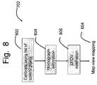
- FIG. 8depicts the procedures to calibrate a normal static camera
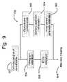
- FIG. 9depicts the procedure to perform the PTZ camera calibration
- FIG. 10illustrates the human model and the human size statistic table
- FIG. 11depicts an example case that the site map may be an aerial photo, in which enough control points may be available;
- FIG. 12illustrates another application example that may use a building blueprint as the site map
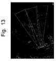
- FIG. 13illustrates another example case where only a map may be available but no control points
- FIG. 14illustrates how to provide camera connection information through GUI
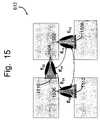
- FIG. 15illustrates a camera network model
- FIG. 16depicts a conceptual block diagram of map target engine
- FIG. 17illustrates some examples of the wide area site-based event detection and responses.
- FIG. 18illustrates how to build an exemplary large system using a scalable structure.
- a “video”may refer to motion pictures represented in analog and/or digital form. Examples of video may include: television, movies, image sequences from a video camera or other observer, and computer-generated image sequences.
- a “frame”may refer to a particular image or other discrete unit within a video.
- An “object”may refer to an item of interest in a video. Examples of an object may include: a person, a vehicle, an animal, and a physical subject.
- a “target”may refer to a computer model of an object.
- the targetmay be derived from the image processing, with a one to one correspondence between targets and objects.
- a “view”may refer to what a camera may see for a particular camera viewing position.
- a cameramay have multiple views if its position or viewing angle change.
- a “map” or a “site map”may refer to an image or graphical representation of the site of interest. Examples of a map may include: an aerial photograph, a blueprint, a computer graphical drawing, a video frame, or a normal photograph of the site.
- a “view target”may refer to a target from each single camera IVS system and the associated site location information, for each camera.
- a “map target”may refer to an integrated model of an object on the map. Each map target may at one time correspond to one and only one object in the real world, but may include several view targets.
- a “video sensor”may refer to an IVS system which only processes one camera feed.
- the inputsmay be the frame, and outputs may be tracked targets in that particular camera field of view (FOV).
- FOVcamera field of view
- a “fusion sensor”may refer to the present cross-camera site IVS system which may not process raw video frames.
- the inputsmay be view target data from a single IVS system, or may be map target data from other fusion sensors.
- a “sensor”may refer to any apparatus for obtaining information about events occurring in a view. Examples include: color and monochrome cameras, video cameras, static cameras, pan-tilt-zoom cameras, omni-cameras, closed-circuit television (CCTV) cameras, charge-coupled device (CCD) sensors, analog and digital cameras, PC cameras, web cameras, tripwire event detectors, loitering event detectors, and infra-red-imaging devices. If not more specifically described, a “camera” refers to any sensing device.
- a “computer”refers to any apparatus that is capable of accepting a structured input, processing the structured input according to prescribed rules, and producing results of the processing as output.
- the computercan include, for example, any apparatus that accepts data, processes the data in accordance with one or more stored software programs, generates results, and typically includes input, output, storage, arithmetic, logic, and control units.
- Examples of a computerinclude: a computer; a general purpose computer; a supercomputer; a mainframe; a super mini-computer; a mini-computer; a workstation; a micro-computer; a server; an interactive television; a web appliance; a telecommunications device with internet access; a hybrid combination of a computer and an interactive television; a portable computer; a personal digital assistant (PDA); a portable telephone; and application-specific hardware to emulate a computer and/or software, for example, a programmable gate array (PGA) or a programmed digital signal processor (DSP).
- a computercan be stationary or portable.
- a computercan have a single processor or multiple processors, which can operate in parallel and/or not in parallel.
- a computeralso refer to two or more computers connected together via a network for transmitting or receiving information between the computers.
- An example of such a computermay include a distributed computer system for processing information via computers linked by a network.
- a “computer-readable medium”may refer to any storage device used for storing data accessible by a computer. Examples of a computer-readable medium include: a magnetic hard disk; a floppy disk; an optical disk, such as a CD-ROM and a DVD; a magnetic tape; and a memory chip.
- Softwaremay refer to prescribed rules to operate a computer. Examples of software include: software; code segments; instructions; software programs; computer programs; and programmed logic.
- a “computer system”may refer to a system having a computer, where the computer comprises a computer-readable medium embodying software to operate the computer.
- a “network”may refer to a number of computers and associated devices that may be connected by communication facilities.
- a networkmay involve permanent connections such as cables or temporary connections such as those made through telephone, wireless, or other communication links.
- Examples of a networkinclude: an internet, such as the Internet; an intranet; a local area network (LAN); a wide area network (WAN); and a combination of networks, such as an internet and an intranet.
- Embodiments of the present inventionmay be based on existing single camera IVS systems with increased automatic situation awareness capability under both spatial and temporal domains.
- the input to the systemmay be content analysis results from multiple individual cameras, such as tracked humans and vehicles.
- the outputmay be tracked targets in the site under monitoring and global events detected by the system.
- the task of the systemmay be to perform data fusion on the information from individual sensors and provide more reliable and powerful surveillance capability.
- a first challengemay be to determine how to associate the targets from different cameras.
- the individual cameras or sensorsusually may be looking at different areas; and they may or may not have overlapped fields of view.
- a physical targetmay be detected, it may be detected simultaneously by multiple cameras but with different target ids.
- a targetmay also be detected by the same or different camera at different times.
- the inventive systemmay receive detected targets from different cameras for every sample moment. How to reliably associate the different detected targets that correspond to the same physical target may be difficult.
- the new technologiesmay include: map-based static, PTZ and omni camera calibration methods; camera network traffic models; human relative size maps; appearance-based target verification; and target fusion algorithms.
- a second challengemay be to determine how to provide prompt and easy understandable global and local situation awareness.
- the wide-area multi-sensor IVSalso may need to integrate the potentially duplicated events produced by different individual IVS sensors so as not to confuse the operators.
- embodiments of the present inventionmay include a general site model, together with a site-based event detector.
- a third challengemay be to determine how to support a large number of cameras and sensors. Since the data may come from distributed sensors and possibly out of sequential order, the data may need to be synchronized with a minimum amount of latency. Data communication among cameras and a center unit may be viable, but increasing the number of cameras may cause a bandwidth limitation issue. Embodiments of the present invention may include a scalable architecture developed to remove this potential limitation.
- FIG. 1depicts an exemplary application scenario for the present invention.
- a conventional IVS systemonly monitors the FOV of each individual camera.
- Embodiments of the present inventionmay monitor both the spatial and temporal domains. Spatially, the monitoring area from an individual camera FOV may be expanded to the whole site of interest by fusing the information gathered by the multiple cameras in the site. Temporally, each target may be tracked for a much longer period of time, even if the target may be temporarily outside of a FOV.
- the systemmay recognize that it was still the same target that appeared a while ago using some new appearance verification technologies of the invention. For example, an object following a path indicated by the dashed lines 112 or 114 may be tracked around the building and determined not to be suspicious, while an object following a path indicated by the dotted line 116 may be tracked and found to be suspicious when it re-enters the FOV of camera 102 .
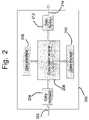
- FIG. 2depicts a conceptual block diagram of an embodiment of the present cross-camera site IVS system 200 , which includes input data 202 , a data receiver 204 , a data fusion engine 206 , a user interface 208 , a data storage 210 , a data sender 212 and output data 214 .
- the input data 202may include the information gathered by lower-level IVS systems, including other cross-camera site IVS systems (e.g., fusion sensors) as well as individual IVS systems (e.g., video cameras).
- the input data 202may be targets, video frames, and/or camera coordinates (e.g., pan-tilt-zoom (PTZ) coordinates).
- all the sensorsmay use the same time server, in other words, they may use the same clock. This may be achieved, for example, through network time synchronization.
- the input data 202may include a timestamp of the data's own sensor.
- the data receiver 204may contain internal buffers for each input sensor.
- a major task of the data receiver 204may be to synchronize the input data 202 and pass them to the data fusion engine 206 .
- the user interface 208may be used to obtain necessary information about the site and the system from the user, and provide visual assistance to the operator for better situation awareness.
- the data fusion engine 206may build and maintain the site model, integrate the corresponding input map and view targets into the map targets in the current site, detect all the events of interest in the site and perform user desired responses to these events.
- Data storage unit 210may store and manage all the useful information used or generated by the system.
- Data sender 212may be in charge of sending controls to any PTZ cameras in the system and sending map targets to the higher level fusion sensors.
- the output data 214may be map targets, current site information and/or other camera commands, e.g., PTZ commands.
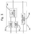
- FIG. 3depicts a conceptual block diagram of the data receiver 204 .
- Module 302may include a list of target buffers and module 304 may include a list of image buffers.
- Each input sensormay have its own target buffer and image buffer. These buffers may be time indexed.
- the buffermay check the timestamp of that data to compare with the current system time. If the latency may be greater than the system allowed latency, the buffer may discard the data and ask for newer data.
- Data synchronizer 306may check the buffers in variable frequency based on the working load of the fusion system and the processing frame rate of the input sensors.
- the outputs of data synchronizer 306 to the data fusion engine 206may include target data from different sensors but with a very narrow time window.
- Module 308may be dedicated to PTZ camera controls. The pan, tilt and zoom values of a PTZ camera may be required to calibrate the camera on to the site model.
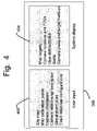
- FIG. 4lists the major components of the user interface 208 .
- Block 402may include the data to be obtained from the operator.
- Block 404may include the information extracted from the scene, which may be used to provide the operator with better visual perception and situation awareness.
- the first user-supplied item that the system may requireis the site map. Examples of a site map include: a satellite image of the site, a blue print of the site, an aerial photograph of the site, a computer graphical drawing of the site, or even a normal photograph of the site.
- the purpose of the site mapmay be to assist the user to set up the global view of the site under surveillance.
- the map calibration pointsmay be a list of pairs of map points and image points.
- the map calibration pointsmay be optional input, and may be needed only when both the map and enough control points on the map are available.
- the control pointmay refer to a point on that map having an easily-identified corresponding point in the video frame.
- Camera informationmay refer to the specific properties of each camera, such as camera type, map location, lens specifications, etc.
- Camera relationship descriptionmay be needed when both the site map and the camera information are lacking.
- the relationship descriptionprovides the normal entry/exit regions in each camera view and each potential path of a target moving from one camera view to another camera view.
- Embodiments of the present inventionmay provide a wide range of visual information in addition to the source videos.
- the systemmay, for example, mark up the targets in both the source video frame and the site map in real-time; display the camera locations on the map and their fixed (for static camera) or moving (PTZ camera) field of views; and display an alert once the event is triggered.
- FIG. 5depicts the main components of the data fusion engine 206 .
- the site model manager 502may be in charge of building and maintaining the site model, which may include the camera to site calibration information and the site traffic information.
- the target fusion engine 504may be used to combine all the corresponding view targets from the same or different video sensors into a map target which corresponds to each individual object in the site.
- Event detection and response engine 506may be used to detect any event of interest and handle detected event of interest according to the user pre-set configurations.
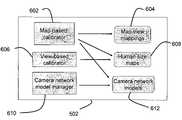
- FIG. 6depicts a conceptual block diagram of the site model manager 502 .
- Map-view mappings 604may store the camera to site map calibration information and provide the corresponding map location for each video frame pixel and the corresponding image location for each map point. This mapping relationship may be created by the map-based calibrator 602 , which may support at least three types of cameras: normal static camera, PTZ camera, and omni-camera. In the wide-area IVS systems, physical location, size and velocity in the site for each target in the video frame may be needed. Knowing both the intrinsic and extrinsic camera parameters, referred as camera calibration, may be very useful for this purpose.
- Traditional camera calibrationmay be performed by viewing a three-dimensional (3D) reference object with a known Euclidean structure.
- 3Dthree-dimensional
- An example of this approachis described, for example, in R. Y. Tsai. “A Versatile Camera Calibration Technique for High-Accuracy 3D Machine Vision Metrology Using Off-the-Shelf TV Cameras and Lenses,” IEEE Journal of Robotics and Automation, 3(4):323-344, August 1987, which may be herein incorporated by reference.
- This type of techniquemay yield the best results if the 3D geometry of the reference object is known with high accuracy.
- this type of techniquemay be directly applicable to multi-camera systems by simply repeating the calibration process independently for each camera.
- setting up the 3D reference object with great accuracymay be an elaborate task that requires special equipment and becomes more difficult as the dimensions of the view volume increase.
- Camera parametersmay be recovered from homographs between the model plane and the image plane computed from correspondences between the reference points and their projections.
- a homographmay be a matrix associating two 3D planes in a space.
- Embodiments of the present inventionmay use new methods to quickly and accurately extract the physical location and size of a target, as well as to guide the PTZ cameras in the site to focus on the targets of interest.
- the site-model managermay need to provide three types of information: the site map location of each view target; the actual size of the target; and the object traffic model of the site. These types of information may be stored in map-view mappings 604 , human size maps 608 and camera network models 612 , which may be created and managed by map-based calibrator 602 , view-based calibrator 606 and camera network model manager 610 , respectively.
- FIG. 7illustrates the three exemplary modules in the map-based calibrator 602 .
- Module 702may be used to calibrate normal static cameras
- module 704may be used to calibrate PTZ cameras
- module 706may be specially used for omni-cameras.
- FIG. 8shows an exemplary procedure to calibrate a normal static camera, as performed by module 702 .
- a homograph estimation methodmay generate an image to site map mapping.
- a homograph Hmay be a 3 ⁇ 3 matrix associating two 3D planes in the space. It may be used extensively to map one 3D place to an image plane, or two image planes from different cameras.
- the ground plane in the video framemay be calibrated to the ground on the site map by using some landmark control points. The minimum number of control point pairs may be four.
- the map-to-image homographsmay be computed for all the static cameras. Since every camera view may be mapping onto the same site map, all of the cameras may be automatically co-calibrated.
- the static camera calibratormay also estimate the effective field of view (EFOV) of each camera on the map.
- EFOVeffective field of view
- This EFOVmay provide the user the effective monitoring area of each camera in the site. If a target of interest, e.g. a human, moves out of the EFOV, the video sensor may not be able to detect and track it reliably due mainly to the small target image size.
- the accuracy of the EFOVmay not only help the user to plan the camera placements, but may also be used for the target fusion engine to perform cross camera target handoff.
- an average human image size at this locationmust be greater than a threshold T_human_min_image_size, which may be determined by the sensitivity of each video sensor; and, the mapping imprecision from the image to the map must be less than a threshold T_max_mapping_imprecision.
- the second criterionmay be to ensure that the mapping between each camera view image and the site map may be generally fairly accurate.
- FIG. 9depicts the procedure to perform the PTZ camera calibration, as performed by block 706 .
- the exact camera extrinsic calibration parametersmay need to be known, including camera map location and height, initial pan, tilt, roll angles and zoom level, and the camera relative intrinsic calibration parameters, including especially the relative focal length compared to the image size.
- Embodiments of the present inventionmay use a method to estimate the camera calibration parameters that may only need to compute one 2D plane (site map) to image plane mapping. This may be much simpler to operate in practice than the conventional calibration methods.
- the userselects control points.
- the user selected control points 802may be used to compute the homograph between the map ground plane and the image ground plane.
- the EFOV of the camera on the mapmay be estimated.
- an initial estimate on the camera calibration parametersmay be provided.
- the calibration matrixmay be derived through the camera rotation, translation and projection operations, thereby setting up coordination transformation between image space and map space. Note that the homograph that was obtained earlier may be doing the same job.
- the main taskmay be to refine the camera calibration estimation to make the calibration matrix consistent with the homograph matrix. The refinement may be done by iteratively searching the parameter space around the initial values using coarse to fine steps.
- one set of camera calibration parametersmay correspond to one and only one homograph between one 3D world plane and the image plane.
- the final optimal calibration parametersmay be the values that generate minimum mean control points matching error. Since the inventive system may assume the ground of the site is a plane, which may not be perfectly satisfied in practice, this final matching error may be also one type of accuracy measure on this assumption and the precision on the user input control points. The smaller the error, the more accurate the estimated map-view mapping may be.
- the final homograph and the EFOVmay be then recomputed using the new control points obtained through the final camera calibration parameters.
- the map-view mapping 604may provide the physical location information of each view target, especially when the view target footprint may be used as the location and velocity estimation. But since the site map may be a 2D representation, the exact 3D dimensions of the target may be still lacking. This physical size information may be used to perform tasks such as target classification.
- Human size map 608may be used to provide the physical size information of each map target.
- the human size map 608may be a frame size lookup table that shows, on each image position, what the expected average human image height and image area are.
- the target's relative sizemay be compared to the expected average human size at that image position.
- the target's relative sizemay be converted to an absolute physical size using an estimated average human size, for example, 1.75 meters in height and 0.5 meters in width and depth.
- the mapmay be generated by projecting the 3D human object back onto the image.
- the human size mapmay be generated by self-learning.
- self-learninghuman detection and tracking may be performed on each sensor.
- the human modelmay include two parts: the head model 1002 and shape model 1004 .
- a head detection and trackermay be used to detect and track human heads.
- the systemmay require that a human object must be of a certain shape, specifically, the height to width ratio must be within a certain range.
- the probability that the target is a humanmay be very high (e.g., greater than 99.5% certain). As shown in FIG.
- these high probability targetsmay be added into the human size statistic table.
- Each section of the tablerepresents an area of the image.
- the shade of the sectionrepresents the average size of human observed at area of the image. In this case, the darker the section, the larger the average size of observed humans. (The fact that the shaded area may be resembles a human head and shoulders may be coincidental.)
- the human size mapmay be generated by averaging and interpolating on the human size statistic table.
- Embodiments of the wide-area site-based IVS system of the present inventionmay support a flexible site model.
- the site map that the system supportsmay be in several formats.
- FIG. 11shows a site map that may be an aerial photo, in which enough control points may be available.
- map-view mapping 604 and human size map 608may be directly computed, and the camera network model 612 may also be obtained indirectly.
- FIG. 12illustrates another example where the site map may be a building blueprint.
- control pointsmay be available, for example, a corner of the room.
- FIG. 13illustrates an example case where the map may be available but there may be no control points.
- user input estimate camera FOVsmay be accepted by the system to provide an initial setup on the camera network model 612 .
- a connection between two camerasincludes two parts: the connecting entry/exit regions on both cameras and the approximate physical distance between the two entry/exit regions.
- entry/exit regions 1402 and 1404separated by a distance D 1 form a connection.
- the camera network model 612may be created and then continuously updated by the camera network model manager using the past high confidence map targets.
- high confidencemay mean that the map target may be consistent in size and shape and may have been tracked by the system for a relatively long duration.
- FIG. 15illustrates an exemplary camera network model 612 .
- Each camera 1502 , 1504 , 1506may have a FOV 1508 , 1510 , 1512 , respectively.
- Each FOVmay have at least one entry/exit point, designated as E 11 , E 12 , E 21 , E 22 , E 31 , and E 32 .
- E 11 , E 12 , E 21 , E 22 , E 31 , and E 32A path from E 21 to E 11 is possible, while a path from E 22 directly to E 12 is not possible.
- An objectmay, for example, exit FOV 1510 and later enter FOV 1508 , and the system may be able to determine that the targets from camera 1504 and camera 1502 were the same target based on the network model and the appearance matching.
- FIG. 16depicts one iteration of map target fusion engine process 504 .
- the map target enginemay have four pipeline processes.
- the first module 1602may update view targets.
- each view targetmay correspond to one image target produced by each video sensor.
- a view targetmay further have a map location and size information.
- the correspondence between the view target and the image targetmay be the view target ID.
- One map targetmay contain multiple view targets from different views or from the same view but in different temporal segments.
- the map targetmay have a primary view target that provides the most reliable representation of the physical object at that time.
- the view target fusion modulelooks for any stable new view targets to see if they belong to any existing map targets. If the new view target matches an existing map target, it will be merged into this map target in block 1604 , and trigger the map target update in block 1606 . Otherwise, the system may produce a new map target based on the new view target.
- the matching measure between two targetsmay be the combination of three probabilities: the location matching probability, the size matching probability and the appearance matching probability.
- the location matching probabilitymay be estimated using the target map location from the map view mapping and the camera network traffic model.
- the size matching probabilitymay be computed from the relative human size value of each target.
- the appearance matching probabilitymay be obtained by comparing the two appearance models of the targets under investigation.
- the appearance model of an exemplary embodimentmay be a distributed intensity histogram, which includes multiple histograms for different spatial partitions of the target.
- the appearance matchingmay be the average correlation between the corresponding spatial partitioned histograms.
- the tasks of the map target update process in block 1606may be to determine the primary view target and update the general target properties such as map location, velocity, classification type and stability status, etc. Since target occlusion may cause significant map location estimation errors, a map target needs also to be tested for whether it actually corresponds to another existing map target when the map target switches from one stable status to a different stable status. A stable status means the target has consistent shape and size in a temporal window. One map target may have multiple different stable periods due to occlusions.
- the map target fusion module 1608may merge two matching map targets in to the one map target that has a longer history.
- FIG. 17illustrates some examples of the wide area site-based event detection and responses from event detect and response engine 506 .
- the site model and the cross camera tracking of the map targetsmay enable performance of wide-area site-based event detection, which is what the traditional single camera based IVS cannot provide.
- Tripwire event detector 1702 and loitering event detector 1704may be two typical examples.
- the definition of the rule and detection of the eventsmay be very similar to those in single camera IVS system: only use site map to replace video frame; and use map target to replace view target. These wide-area map-based events may be used in addition to the single camera based event detections.
- the automatic target close up monitoring using PTZ camerasmay be performed.
- the usermay require PTZ camera to zoom-in and follow the target as one type of event response.
- the systemmay determine the pan, tilt and zoom level of a dedicated PTZ camera and may control the camera to follow the target of interest.
- the hand-off from one PTZ camera to another PTZ camera in the sitemay be also developed. This may be achieved by automatically selecting the camera which can provide the required target coverage with the smallest zoom-in level.
- a larger zoom-in valueusually makes the video more sensitive to camera stabilization and PTZ command latencies, which may be undesirable for this application scenario.
- FIG. 18illustrates how to build an exemplary large system using a scalable structure, where the individual IVS system may be a video sensor and site-based multiple IVS system may act as a fusion sensor.
- This multi-level structureensures that each fusion sensor only processes a limited amount of input data. The major requirement may be that every fusion sensor use the same site map coordinates, thus the fusion sensor at lower levels only monitors a portion of the top level site.
Landscapes
- Engineering & Computer Science (AREA)
- Physics & Mathematics (AREA)
- General Physics & Mathematics (AREA)
- Multimedia (AREA)
- Theoretical Computer Science (AREA)
- Computer Vision & Pattern Recognition (AREA)
- Computer Security & Cryptography (AREA)
- Closed-Circuit Television Systems (AREA)
Abstract
Description
Claims (21)
Priority Applications (4)
| Application Number | Priority Date | Filing Date | Title |
|---|---|---|---|
| US11/098,579US7583815B2 (en) | 2005-04-05 | 2005-04-05 | Wide-area site-based video surveillance system |
| TW095111993ATW200708102A (en) | 2005-04-05 | 2006-04-04 | Wide-area site-based video surveillance system |
| US11/397,930US20080291278A1 (en) | 2005-04-05 | 2006-04-05 | Wide-area site-based video surveillance system |
| PCT/US2006/012558WO2006107999A2 (en) | 2005-04-05 | 2006-04-05 | Wide-area site-based video surveillance system |
Applications Claiming Priority (1)
| Application Number | Priority Date | Filing Date | Title |
|---|---|---|---|
| US11/098,579US7583815B2 (en) | 2005-04-05 | 2005-04-05 | Wide-area site-based video surveillance system |
Related Child Applications (1)
| Application Number | Title | Priority Date | Filing Date |
|---|---|---|---|
| US11/397,930Continuation-In-PartUS20080291278A1 (en) | 2005-04-05 | 2006-04-05 | Wide-area site-based video surveillance system |
Publications (2)
| Publication Number | Publication Date |
|---|---|
| US20060222209A1 US20060222209A1 (en) | 2006-10-05 |
| US7583815B2true US7583815B2 (en) | 2009-09-01 |
Family
ID=37070530
Family Applications (1)
| Application Number | Title | Priority Date | Filing Date |
|---|---|---|---|
| US11/098,579Active2026-12-22US7583815B2 (en) | 2005-04-05 | 2005-04-05 | Wide-area site-based video surveillance system |
Country Status (3)
| Country | Link |
|---|---|
| US (1) | US7583815B2 (en) |
| TW (1) | TW200708102A (en) |
| WO (1) | WO2006107999A2 (en) |
Cited By (32)
| Publication number | Priority date | Publication date | Assignee | Title |
|---|---|---|---|---|
| US20060227997A1 (en)* | 2005-03-31 | 2006-10-12 | Honeywell International Inc. | Methods for defining, detecting, analyzing, indexing and retrieving events using video image processing |
| US20070035612A1 (en)* | 2005-08-09 | 2007-02-15 | Korneluk Jose E | Method and apparatus to capture and compile information perceivable by multiple handsets regarding a single event |
| US20080143821A1 (en)* | 2006-12-16 | 2008-06-19 | Hung Yi-Ping | Image Processing System For Integrating Multi-Resolution Images |
| US20080279452A1 (en)* | 2007-03-30 | 2008-11-13 | Michael Keane | Virtual Earth Image Isolation System |
| US20090015460A1 (en)* | 2006-06-08 | 2009-01-15 | Fox Philip A | Radar visibility model |
| US20090027501A1 (en)* | 2007-07-27 | 2009-01-29 | Sportvision, Inc. | Detecting an object in an image using camera registration data indexed to location or camera sensors |
| US20100073475A1 (en)* | 2006-11-09 | 2010-03-25 | Innovative Signal Analysis, Inc. | Moving object detection |
| US20100321473A1 (en)* | 2007-10-04 | 2010-12-23 | Samsung Techwin Co., Ltd. | Surveillance camera system |
| US20110090358A1 (en)* | 2009-10-19 | 2011-04-21 | Canon Kabushiki Kaisha | Image pickup apparatus, information processing apparatus, and information processing method |
| US20110169867A1 (en)* | 2009-11-30 | 2011-07-14 | Innovative Signal Analysis, Inc. | Moving object detection, tracking, and displaying systems |
| US20110181733A1 (en)* | 2010-01-26 | 2011-07-28 | Sanyo Electric Co., Ltd. | Calibrating apparatus |
| US8193909B1 (en)* | 2010-11-15 | 2012-06-05 | Intergraph Technologies Company | System and method for camera control in a surveillance system |
| US20120243730A1 (en)* | 2011-03-22 | 2012-09-27 | Abdelkader Outtagarts | Collaborative camera services for distributed real-time object analysis |
| US8311275B1 (en) | 2008-06-10 | 2012-11-13 | Mindmancer AB | Selective viewing of a scene |
| US8478711B2 (en) | 2011-02-18 | 2013-07-02 | Larus Technologies Corporation | System and method for data fusion with adaptive learning |
| US9147260B2 (en) | 2010-12-20 | 2015-09-29 | International Business Machines Corporation | Detection and tracking of moving objects |
| US9294757B1 (en)* | 2013-03-15 | 2016-03-22 | Google Inc. | 3-dimensional videos of objects |
| US9374870B2 (en) | 2012-09-12 | 2016-06-21 | Sensity Systems Inc. | Networked lighting infrastructure for sensing applications |
| US9456293B2 (en) | 2013-03-26 | 2016-09-27 | Sensity Systems Inc. | Sensor nodes with multicast transmissions in lighting sensory network |
| US9582671B2 (en) | 2014-03-06 | 2017-02-28 | Sensity Systems Inc. | Security and data privacy for lighting sensory networks |
| US9746370B2 (en) | 2014-02-26 | 2017-08-29 | Sensity Systems Inc. | Method and apparatus for measuring illumination characteristics of a luminaire |
| US9760792B2 (en) | 2015-03-20 | 2017-09-12 | Netra, Inc. | Object detection and classification |
| US9922271B2 (en) | 2015-03-20 | 2018-03-20 | Netra, Inc. | Object detection and classification |
| US9933297B2 (en) | 2013-03-26 | 2018-04-03 | Sensity Systems Inc. | System and method for planning and monitoring a light sensory network |
| US10033992B1 (en) | 2014-09-09 | 2018-07-24 | Google Llc | Generating a 3D video of an event using crowd sourced data |
| US10139819B2 (en) | 2014-08-22 | 2018-11-27 | Innovative Signal Analysis, Inc. | Video enabled inspection using unmanned aerial vehicles |
| US10362112B2 (en) | 2014-03-06 | 2019-07-23 | Verizon Patent And Licensing Inc. | Application environment for lighting sensory networks |
| US10417570B2 (en) | 2014-03-06 | 2019-09-17 | Verizon Patent And Licensing Inc. | Systems and methods for probabilistic semantic sensing in a sensory network |
| WO2020219873A1 (en)* | 2019-04-24 | 2020-10-29 | Hubbell Incorporated | System and method for integrated surveillance and communication into lighting equipment |
| US10908678B2 (en) | 2017-04-28 | 2021-02-02 | FLIR Belgium BVBA | Video and image chart fusion systems and methods |
| US12380701B2 (en) | 2023-05-18 | 2025-08-05 | SanDisk Technologies, Inc. | Predictive adjustment of multi-camera surveillance video data capture |
| US12401765B2 (en) | 2023-06-27 | 2025-08-26 | SanDisk Technologies, Inc. | Predictive adjustment of multi-camera surveillance video data capture using graph maps |
Families Citing this family (48)
| Publication number | Priority date | Publication date | Assignee | Title |
|---|---|---|---|---|
| US8564661B2 (en) | 2000-10-24 | 2013-10-22 | Objectvideo, Inc. | Video analytic rule detection system and method |
| US8711217B2 (en) | 2000-10-24 | 2014-04-29 | Objectvideo, Inc. | Video surveillance system employing video primitives |
| US9892606B2 (en) | 2001-11-15 | 2018-02-13 | Avigilon Fortress Corporation | Video surveillance system employing video primitives |
| US7424175B2 (en)* | 2001-03-23 | 2008-09-09 | Objectvideo, Inc. | Video segmentation using statistical pixel modeling |
| US7956890B2 (en)* | 2004-09-17 | 2011-06-07 | Proximex Corporation | Adaptive multi-modal integrated biometric identification detection and surveillance systems |
| US20060066719A1 (en)* | 2004-09-24 | 2006-03-30 | Objectvideo, Inc. | Method for finding paths in video |
| US20080166015A1 (en) | 2004-09-24 | 2008-07-10 | Object Video, Inc. | Method for finding paths in video |
| JP2009509582A (en)* | 2005-09-22 | 2009-03-12 | スリーエム イノベイティブ プロパティズ カンパニー | Artifact reduction in 3D imaging |
| KR101392294B1 (en) | 2006-04-17 | 2014-05-27 | 오브젝트비디오 인코퍼레이티드 | Video segmentation using statistical pixel modeling |
| TW200822751A (en)* | 2006-07-14 | 2008-05-16 | Objectvideo Inc | Video analytics for retail business process monitoring |
| US20080074496A1 (en)* | 2006-09-22 | 2008-03-27 | Object Video, Inc. | Video analytics for banking business process monitoring |
| US8531521B2 (en)* | 2006-10-06 | 2013-09-10 | Sightlogix, Inc. | Methods and apparatus related to improved surveillance using a smart camera |
| US8401240B2 (en)* | 2006-11-09 | 2013-03-19 | University Of Florida Research Foundation, Inc. | Passive single camera imaging system for determining motor vehicle speed |
| US7777783B1 (en) | 2007-03-23 | 2010-08-17 | Proximex Corporation | Multi-video navigation |
| US9544563B1 (en) | 2007-03-23 | 2017-01-10 | Proximex Corporation | Multi-video navigation system |
| US20080273754A1 (en)* | 2007-05-04 | 2008-11-06 | Leviton Manufacturing Co., Inc. | Apparatus and method for defining an area of interest for image sensing |
| US9646312B2 (en)* | 2007-11-07 | 2017-05-09 | Game Design Automation Pty Ltd | Anonymous player tracking |
| DE102007053812A1 (en)* | 2007-11-12 | 2009-05-14 | Robert Bosch Gmbh | Video surveillance system configuration module, configuration module monitoring system, video surveillance system configuration process, and computer program |
| EP2093636A1 (en)* | 2008-02-21 | 2009-08-26 | Siemens Aktiengesellschaft | Method for controlling an alarm management system |
| US9398266B2 (en)* | 2008-04-02 | 2016-07-19 | Hernan Carzalo | Object content navigation |
| WO2009122416A2 (en)* | 2008-04-02 | 2009-10-08 | Evt Technologies Ltd. | Object content navigation |
| US9019381B2 (en) | 2008-05-09 | 2015-04-28 | Intuvision Inc. | Video tracking systems and methods employing cognitive vision |
| EP2161634A1 (en)* | 2008-09-03 | 2010-03-10 | BAE Systems PLC | Estimating a state of at least one target |
| CA2735787A1 (en)* | 2008-09-03 | 2010-03-11 | Bae Systems Plc | Estimating a state of at least one target |
| US20100318588A1 (en)* | 2009-06-12 | 2010-12-16 | Avaya Inc. | Spatial-Temporal Event Correlation for Location-Based Services |
| EP2270761A1 (en)* | 2009-07-01 | 2011-01-05 | Thales | System architecture and process for tracking individuals in large crowded environments |
| US8564667B2 (en)* | 2009-08-21 | 2013-10-22 | Empire Technology Development Llc | Surveillance system |
| AU2009243528B2 (en)* | 2009-12-04 | 2013-08-01 | Canon Kabushiki Kaisha | Location-based signature selection for multi-camera object tracking |
| TWI416068B (en) | 2009-12-10 | 2013-11-21 | Ind Tech Res Inst | Object tracking method and apparatus for a non-overlapping-sensor network |
| GB201002855D0 (en)* | 2010-02-19 | 2010-04-07 | Materialise Dental Nv | Method and system for achiving subject-specific, three-dimensional information about the geometry of part of the body |
| JP2013186819A (en)* | 2012-03-09 | 2013-09-19 | Omron Corp | Image processing device, image processing method, and image processing program |
| WO2013149340A1 (en) | 2012-04-02 | 2013-10-10 | Mcmaster University | Optimal camera selection iν array of monitoring cameras |
| EP2672694B1 (en)* | 2012-06-05 | 2014-01-15 | Axis AB | Improved control of an image capturing device |
| EP3317680B1 (en)* | 2015-06-26 | 2021-03-31 | INTEL Corporation | System manager to adaptively manage data collection devices in distributed computing systems, corresponding method and corresponding machine readable medium |
| JP6742195B2 (en)* | 2016-08-23 | 2020-08-19 | キヤノン株式会社 | Information processing apparatus, method thereof, and computer program |
| EP3324209A1 (en)* | 2016-11-18 | 2018-05-23 | Dibotics | Methods and systems for vehicle environment map generation and updating |
| EP3619104B1 (en)* | 2017-05-04 | 2021-12-15 | Carnegie Mellon University | State estimation and localization for rov-based structural inspection |
| CN110062198B (en)* | 2018-01-18 | 2022-04-05 | 杭州海康威视数字技术股份有限公司 | Monitoring evidence obtaining method, device and system, electronic equipment and storage medium |
| TWI682368B (en)* | 2018-07-03 | 2020-01-11 | 緯創資通股份有限公司 | Surveillance system and surveillance method using multi-dimensional sensor data |
| US10915796B2 (en)* | 2018-10-30 | 2021-02-09 | Disney Enterprises, Inc. | ID association and indoor localization via passive phased-array and computer vision motion correlation |
| CN111753609B (en)* | 2019-08-02 | 2023-12-26 | 杭州海康威视数字技术股份有限公司 | Target identification method and device and camera |
| CN112128624A (en)* | 2020-06-08 | 2020-12-25 | 广东希睿数字科技有限公司 | A gas digital twin 3D visualization intelligent operation and maintenance system |
| US11755643B2 (en)* | 2020-07-06 | 2023-09-12 | Microsoft Technology Licensing, Llc | Metadata generation for video indexing |
| CA3210157A1 (en)* | 2021-01-29 | 2022-08-04 | Saam, Inc. | Sensor fusion for fire detection & air quality monitoring |
| US20240163402A1 (en)* | 2021-06-18 | 2024-05-16 | Daniel KARIO | System, apparatus, and method of surveillance |
| CN113989761B (en)* | 2021-10-29 | 2025-06-24 | 中汽创智科技有限公司 | Object tracking method, device, electronic device and storage medium |
| CN114708556A (en)* | 2022-04-19 | 2022-07-05 | 北京市商汤科技开发有限公司 | Detection method, detection device, electronic equipment and storage medium |
| JP2024088984A (en)* | 2022-12-21 | 2024-07-03 | キヤノン株式会社 | Information processing device, information processing method, and computer program |
Citations (16)
| Publication number | Priority date | Publication date | Assignee | Title |
|---|---|---|---|---|
| US6359647B1 (en)* | 1998-08-07 | 2002-03-19 | Philips Electronics North America Corporation | Automated camera handoff system for figure tracking in a multiple camera system |
| US20020071033A1 (en)* | 2000-12-12 | 2002-06-13 | Philips Electronics North America Corporation | Apparatus and methods for resolution of entry/exit conflicts for security monitoring systems |
| US20030023595A1 (en)* | 2001-06-12 | 2003-01-30 | Carlbom Ingrid Birgitta | Method and apparatus for retrieving multimedia data through spatio-temporal activity maps |
| US20030085992A1 (en)* | 2000-03-07 | 2003-05-08 | Sarnoff Corporation | Method and apparatus for providing immersive surveillance |
| US6628835B1 (en) | 1998-08-31 | 2003-09-30 | Texas Instruments Incorporated | Method and system for defining and recognizing complex events in a video sequence |
| US20040008253A1 (en)* | 2002-07-10 | 2004-01-15 | Monroe David A. | Comprehensive multi-media surveillance and response system for aircraft, operations centers, airports and other commercial transports, centers and terminals |
| US20040017930A1 (en) | 2002-07-19 | 2004-01-29 | Samsung Electronics Co., Ltd. | System and method for detecting and tracking a plurality of faces in real time by integrating visual ques |
| US20040066970A1 (en) | 1995-11-01 | 2004-04-08 | Masakazu Matsugu | Object extraction method, and image sensing apparatus using the method |
| US20040075738A1 (en)* | 1999-05-12 | 2004-04-22 | Sean Burke | Spherical surveillance system architecture |
| US20040155960A1 (en)* | 2002-04-19 | 2004-08-12 | Wren Technology Group. | System and method for integrating and characterizing data from multiple electronic systems |
| US20050024206A1 (en)* | 2003-06-19 | 2005-02-03 | Supun Samarasekera | Method and apparatus for providing a scalable multi-camera distributed video processing and visualization surveillance system |
| US20050036036A1 (en)* | 2001-07-25 | 2005-02-17 | Stevenson Neil James | Camera control apparatus and method |
| US20050073585A1 (en)* | 2003-09-19 | 2005-04-07 | Alphatech, Inc. | Tracking systems and methods |
| US6970183B1 (en) | 2000-06-14 | 2005-11-29 | E-Watch, Inc. | Multimedia surveillance and monitoring system including network configuration |
| US20050265582A1 (en)* | 2002-11-12 | 2005-12-01 | Buehler Christopher J | Method and system for tracking and behavioral monitoring of multiple objects moving through multiple fields-of-view |
| US7006950B1 (en)* | 2000-06-12 | 2006-02-28 | Siemens Corporate Research, Inc. | Statistical modeling and performance characterization of a real-time dual camera surveillance system |
- 2005
- 2005-04-05USUS11/098,579patent/US7583815B2/enactiveActive
- 2006
- 2006-04-04TWTW095111993Apatent/TW200708102A/enunknown
- 2006-04-05WOPCT/US2006/012558patent/WO2006107999A2/enactiveApplication Filing
Patent Citations (16)
| Publication number | Priority date | Publication date | Assignee | Title |
|---|---|---|---|---|
| US20040066970A1 (en) | 1995-11-01 | 2004-04-08 | Masakazu Matsugu | Object extraction method, and image sensing apparatus using the method |
| US6359647B1 (en)* | 1998-08-07 | 2002-03-19 | Philips Electronics North America Corporation | Automated camera handoff system for figure tracking in a multiple camera system |
| US6628835B1 (en) | 1998-08-31 | 2003-09-30 | Texas Instruments Incorporated | Method and system for defining and recognizing complex events in a video sequence |
| US20040075738A1 (en)* | 1999-05-12 | 2004-04-22 | Sean Burke | Spherical surveillance system architecture |
| US20030085992A1 (en)* | 2000-03-07 | 2003-05-08 | Sarnoff Corporation | Method and apparatus for providing immersive surveillance |
| US7006950B1 (en)* | 2000-06-12 | 2006-02-28 | Siemens Corporate Research, Inc. | Statistical modeling and performance characterization of a real-time dual camera surveillance system |
| US6970183B1 (en) | 2000-06-14 | 2005-11-29 | E-Watch, Inc. | Multimedia surveillance and monitoring system including network configuration |
| US20020071033A1 (en)* | 2000-12-12 | 2002-06-13 | Philips Electronics North America Corporation | Apparatus and methods for resolution of entry/exit conflicts for security monitoring systems |
| US20030023595A1 (en)* | 2001-06-12 | 2003-01-30 | Carlbom Ingrid Birgitta | Method and apparatus for retrieving multimedia data through spatio-temporal activity maps |
| US20050036036A1 (en)* | 2001-07-25 | 2005-02-17 | Stevenson Neil James | Camera control apparatus and method |
| US20040155960A1 (en)* | 2002-04-19 | 2004-08-12 | Wren Technology Group. | System and method for integrating and characterizing data from multiple electronic systems |
| US20040008253A1 (en)* | 2002-07-10 | 2004-01-15 | Monroe David A. | Comprehensive multi-media surveillance and response system for aircraft, operations centers, airports and other commercial transports, centers and terminals |
| US20040017930A1 (en) | 2002-07-19 | 2004-01-29 | Samsung Electronics Co., Ltd. | System and method for detecting and tracking a plurality of faces in real time by integrating visual ques |
| US20050265582A1 (en)* | 2002-11-12 | 2005-12-01 | Buehler Christopher J | Method and system for tracking and behavioral monitoring of multiple objects moving through multiple fields-of-view |
| US20050024206A1 (en)* | 2003-06-19 | 2005-02-03 | Supun Samarasekera | Method and apparatus for providing a scalable multi-camera distributed video processing and visualization surveillance system |
| US20050073585A1 (en)* | 2003-09-19 | 2005-04-07 | Alphatech, Inc. | Tracking systems and methods |
Non-Patent Citations (4)
| Title |
|---|
| Kumar, et al., Aerial Video Surveillance and Exploitation, Proceedings of the IEEE, vol. 89, Oct. 2001, pp. 1518-1539. |
| P.F. Sturm and S.J. Maybank, "On Plane-Based Camera Calibration: A General Algorithm, Singularities, Applications," Proc. Computer Vision and Pattern Recognition, vol. 1, pp. 432-437, 1999. |
| R. Y. Tsai, "A Versatile Camera Calibration Technique for High-Accuracy 3D Machine Vision Metrology Using Off-The-Shelf TV Cameras and Lenses," IEEE Journal of Robotics and Automation, 3(4), pp. 323-344, Aug. 1987. |
| Z. Zhang, "Flexible Camera Calibration by Viewing a Plane From Unknown Orientations," Proc. 7th International Conference on Computer Vision, vol. 1, pp. 666-673, 1999. |
Cited By (65)
| Publication number | Priority date | Publication date | Assignee | Title |
|---|---|---|---|---|
| US7801328B2 (en)* | 2005-03-31 | 2010-09-21 | Honeywell International Inc. | Methods for defining, detecting, analyzing, indexing and retrieving events using video image processing |
| US20060227997A1 (en)* | 2005-03-31 | 2006-10-12 | Honeywell International Inc. | Methods for defining, detecting, analyzing, indexing and retrieving events using video image processing |
| US20070035612A1 (en)* | 2005-08-09 | 2007-02-15 | Korneluk Jose E | Method and apparatus to capture and compile information perceivable by multiple handsets regarding a single event |
| US9030351B2 (en)* | 2006-06-08 | 2015-05-12 | Vista Research, Inc. | Sensor suite and signal processing for border surveillance |
| US20090015460A1 (en)* | 2006-06-08 | 2009-01-15 | Fox Philip A | Radar visibility model |
| US8330647B2 (en) | 2006-06-08 | 2012-12-11 | Vista Research, Inc. | Sensor suite and signal processing for border surveillance |
| US8026842B2 (en)* | 2006-06-08 | 2011-09-27 | Vista Research, Inc. | Method for surveillance to detect a land target |
| US20100283662A1 (en)* | 2006-06-08 | 2010-11-11 | Fox Phillilp A | Method for surveillance to detect a land target |
| US8026844B2 (en) | 2006-06-08 | 2011-09-27 | Vista Research, Inc. | Radar visibility model |
| US20110001657A1 (en)* | 2006-06-08 | 2011-01-06 | Fox Philip A | Sensor suite and signal processing for border surveillance |
| US9696409B2 (en)* | 2006-06-08 | 2017-07-04 | Vista Research, Inc. | Sensor suite and signal processing for border surveillance |
| US8803972B2 (en) | 2006-11-09 | 2014-08-12 | Innovative Signal Analysis, Inc. | Moving object detection |
| US20100073475A1 (en)* | 2006-11-09 | 2010-03-25 | Innovative Signal Analysis, Inc. | Moving object detection |
| US9413956B2 (en) | 2006-11-09 | 2016-08-09 | Innovative Signal Analysis, Inc. | System for extending a field-of-view of an image acquisition device |
| US20080143821A1 (en)* | 2006-12-16 | 2008-06-19 | Hung Yi-Ping | Image Processing System For Integrating Multi-Resolution Images |
| US7719568B2 (en)* | 2006-12-16 | 2010-05-18 | National Chiao Tung University | Image processing system for integrating multi-resolution images |
| US20080279452A1 (en)* | 2007-03-30 | 2008-11-13 | Michael Keane | Virtual Earth Image Isolation System |
| US8253799B2 (en)* | 2007-07-27 | 2012-08-28 | Sportvision, Inc. | Detecting an object in an image using camera registration data indexed to location or camera sensors |
| US20090027501A1 (en)* | 2007-07-27 | 2009-01-29 | Sportvision, Inc. | Detecting an object in an image using camera registration data indexed to location or camera sensors |
| US20100321473A1 (en)* | 2007-10-04 | 2010-12-23 | Samsung Techwin Co., Ltd. | Surveillance camera system |
| US8508595B2 (en)* | 2007-10-04 | 2013-08-13 | Samsung Techwin Co., Ltd. | Surveillance camera system for controlling cameras using position and orientation of the cameras and position information of a detected object |
| US9172919B2 (en) | 2008-06-10 | 2015-10-27 | Mindmancer AB | Selective viewing of a scene |
| US8965047B1 (en) | 2008-06-10 | 2015-02-24 | Mindmancer AB | Selective viewing of a scene |
| US8311275B1 (en) | 2008-06-10 | 2012-11-13 | Mindmancer AB | Selective viewing of a scene |
| US9237266B2 (en)* | 2009-10-19 | 2016-01-12 | Canon Kabushiki Kaisha | Image pickup apparatus and method for detecting an entrance or exit event of an object in a frame image and medium storing a program causing a computer to function as the apparatus |
| US20110090358A1 (en)* | 2009-10-19 | 2011-04-21 | Canon Kabushiki Kaisha | Image pickup apparatus, information processing apparatus, and information processing method |
| US9679202B2 (en) | 2009-10-19 | 2017-06-13 | Canon Kabushiki Kaisha | Information processing apparatus with display control unit configured to display on a display apparatus a frame image, and corresponding information processing method, and medium |
| US10510231B2 (en) | 2009-11-30 | 2019-12-17 | Innovative Signal Analysis, Inc. | Moving object detection, tracking, and displaying systems |
| US9430923B2 (en)* | 2009-11-30 | 2016-08-30 | Innovative Signal Analysis, Inc. | Moving object detection, tracking, and displaying systems |
| US20110169867A1 (en)* | 2009-11-30 | 2011-07-14 | Innovative Signal Analysis, Inc. | Moving object detection, tracking, and displaying systems |
| US20110181733A1 (en)* | 2010-01-26 | 2011-07-28 | Sanyo Electric Co., Ltd. | Calibrating apparatus |
| US8411999B2 (en)* | 2010-01-26 | 2013-04-02 | Sanyo Electric Co., Ltd. | Calibrating apparatus |
| US20120212611A1 (en)* | 2010-11-15 | 2012-08-23 | Intergraph Technologies Company | System and Method for Camera Control in a Surveillance System |
| US8624709B2 (en)* | 2010-11-15 | 2014-01-07 | Intergraph Technologies Company | System and method for camera control in a surveillance system |
| US8193909B1 (en)* | 2010-11-15 | 2012-06-05 | Intergraph Technologies Company | System and method for camera control in a surveillance system |
| US9147260B2 (en) | 2010-12-20 | 2015-09-29 | International Business Machines Corporation | Detection and tracking of moving objects |
| US8478711B2 (en) | 2011-02-18 | 2013-07-02 | Larus Technologies Corporation | System and method for data fusion with adaptive learning |
| US9002057B2 (en)* | 2011-03-22 | 2015-04-07 | Alcatel Lucent | Collaborative camera services for distributed real-time object analysis |
| US20120243730A1 (en)* | 2011-03-22 | 2012-09-27 | Abdelkader Outtagarts | Collaborative camera services for distributed real-time object analysis |
| US9374870B2 (en) | 2012-09-12 | 2016-06-21 | Sensity Systems Inc. | Networked lighting infrastructure for sensing applications |
| US9699873B2 (en) | 2012-09-12 | 2017-07-04 | Sensity Systems Inc. | Networked lighting infrastructure for sensing applications |
| US9959413B2 (en) | 2012-09-12 | 2018-05-01 | Sensity Systems Inc. | Security and data privacy for lighting sensory networks |
| US9294757B1 (en)* | 2013-03-15 | 2016-03-22 | Google Inc. | 3-dimensional videos of objects |
| US9933297B2 (en) | 2013-03-26 | 2018-04-03 | Sensity Systems Inc. | System and method for planning and monitoring a light sensory network |
| US9456293B2 (en) | 2013-03-26 | 2016-09-27 | Sensity Systems Inc. | Sensor nodes with multicast transmissions in lighting sensory network |
| US10158718B2 (en) | 2013-03-26 | 2018-12-18 | Verizon Patent And Licensing Inc. | Sensor nodes with multicast transmissions in lighting sensory network |
| US9746370B2 (en) | 2014-02-26 | 2017-08-29 | Sensity Systems Inc. | Method and apparatus for measuring illumination characteristics of a luminaire |
| US10791175B2 (en) | 2014-03-06 | 2020-09-29 | Verizon Patent And Licensing Inc. | Application environment for sensory networks |
| US11616842B2 (en) | 2014-03-06 | 2023-03-28 | Verizon Patent And Licensing Inc. | Application environment for sensory networks |
| US11544608B2 (en) | 2014-03-06 | 2023-01-03 | Verizon Patent And Licensing Inc. | Systems and methods for probabilistic semantic sensing in a sensory network |
| US9582671B2 (en) | 2014-03-06 | 2017-02-28 | Sensity Systems Inc. | Security and data privacy for lighting sensory networks |
| US10417570B2 (en) | 2014-03-06 | 2019-09-17 | Verizon Patent And Licensing Inc. | Systems and methods for probabilistic semantic sensing in a sensory network |
| US10362112B2 (en) | 2014-03-06 | 2019-07-23 | Verizon Patent And Licensing Inc. | Application environment for lighting sensory networks |
| US10139819B2 (en) | 2014-08-22 | 2018-11-27 | Innovative Signal Analysis, Inc. | Video enabled inspection using unmanned aerial vehicles |
| US10033992B1 (en) | 2014-09-09 | 2018-07-24 | Google Llc | Generating a 3D video of an event using crowd sourced data |
| US9922271B2 (en) | 2015-03-20 | 2018-03-20 | Netra, Inc. | Object detection and classification |
| US9760792B2 (en) | 2015-03-20 | 2017-09-12 | Netra, Inc. | Object detection and classification |
| US9934447B2 (en) | 2015-03-20 | 2018-04-03 | Netra, Inc. | Object detection and classification |
| US10908678B2 (en) | 2017-04-28 | 2021-02-02 | FLIR Belgium BVBA | Video and image chart fusion systems and methods |
| WO2020219873A1 (en)* | 2019-04-24 | 2020-10-29 | Hubbell Incorporated | System and method for integrated surveillance and communication into lighting equipment |
| US20200342238A1 (en)* | 2019-04-24 | 2020-10-29 | Hubbell Incorporated | System and method for integrated surveillance and communication into lighting equipment |
| US11886642B2 (en)* | 2019-04-24 | 2024-01-30 | Hubbell Incorporated | System and method for integrated surveillance and communication into lighting equipment |
| US12346504B2 (en) | 2019-04-24 | 2025-07-01 | Hubbell Incorporated | System and method for integrated surveillance and communication into lighting equipment |
| US12380701B2 (en) | 2023-05-18 | 2025-08-05 | SanDisk Technologies, Inc. | Predictive adjustment of multi-camera surveillance video data capture |
| US12401765B2 (en) | 2023-06-27 | 2025-08-26 | SanDisk Technologies, Inc. | Predictive adjustment of multi-camera surveillance video data capture using graph maps |
Also Published As
| Publication number | Publication date |
|---|---|
| US20060222209A1 (en) | 2006-10-05 |
| TW200708102A (en) | 2007-02-16 |
| WO2006107999A2 (en) | 2006-10-12 |
| WO2006107999A3 (en) | 2007-03-01 |
Similar Documents
| Publication | Publication Date | Title |
|---|---|---|
| US7583815B2 (en) | Wide-area site-based video surveillance system | |
| US20080291278A1 (en) | Wide-area site-based video surveillance system | |
| EP3985611B1 (en) | Building radar-camera surveillance system | |
| Senior et al. | Acquiring multi-scale images by pan-tilt-zoom control and automatic multi-camera calibration | |
| US20070058717A1 (en) | Enhanced processing for scanning video | |
| US10614311B2 (en) | Automatic extraction of secondary video streams | |
| KR102239530B1 (en) | Method and camera system combining views from plurality of cameras | |
| Boult et al. | Omni-directional visual surveillance | |
| US8150103B2 (en) | Background modeling with feature blocks | |
| Collins et al. | A system for video surveillance and monitoring | |
| US8180107B2 (en) | Active coordinated tracking for multi-camera systems | |
| US8289392B2 (en) | Automatic multiscale image acquisition from a steerable camera | |
| US20100165112A1 (en) | Automatic extraction of secondary video streams | |
| US20050134685A1 (en) | Master-slave automated video-based surveillance system | |
| KR101290782B1 (en) | System and method for Multiple PTZ Camera Control Based on Intelligent Multi-Object Tracking Algorithm | |
| KR101916093B1 (en) | Method for tracking object | |
| US12169620B2 (en) | Video display method, device and system, and video camera | |
| KR20150019230A (en) | Method and apparatus for tracking object using multiple camera | |
| KR101996907B1 (en) | Apparatus for tracking object | |
| Zhang et al. | Video surveillance using a multi-camera tracking and fusion system | |
| Wu et al. | Using scene features to improve wide-area video surveillance | |
| KR20240002340A (en) | System and method for surveilling video using collaboration of PTZ cameras, and a recording medium recording a computer readable program for executing the method | |
| Sheikh et al. | Trajectory association across non-overlapping moving cameras in planar scenes | |
| Redding et al. | Urban video surveillance from airborne and ground-based platforms | |
| Ciurapiński et al. | Data fusion concept in multispectral system for perimeter protection of stationary and moving objects |
Legal Events
| Date | Code | Title | Description |
|---|---|---|---|
| AS | Assignment | Owner name:OBJECTVIDEO, INC., VIRGINIA Free format text:ASSIGNMENT OF ASSIGNORS INTEREST;ASSIGNORS:ZHANG, ZHONG;YU, LI;LIU, HAIYING;AND OTHERS;REEL/FRAME:016928/0920;SIGNING DATES FROM 20050513 TO 20050521 | |
| AS | Assignment | Owner name:OBJECTVIDEO, INC., VIRGINIA Free format text:THE ADDITION OF THREE ASSIGNORS FOR THE ASSIGNMENT RECORDED ON 8/24/05, REEL/FRAME 016928/0920.;ASSIGNORS:ZHANG, ZHONG;YU, LI;LIU, HAIYING;AND OTHERS;REEL/FRAME:017877/0277;SIGNING DATES FROM 20050513 TO 20050521 | |
| AS | Assignment | Owner name:RJF OV, LLC, DISTRICT OF COLUMBIA Free format text:SECURITY AGREEMENT;ASSIGNOR:OBJECTVIDEO, INC.;REEL/FRAME:020478/0711 Effective date:20080208 Owner name:RJF OV, LLC,DISTRICT OF COLUMBIA Free format text:SECURITY AGREEMENT;ASSIGNOR:OBJECTVIDEO, INC.;REEL/FRAME:020478/0711 Effective date:20080208 | |
| AS | Assignment | Owner name:RJF OV, LLC, DISTRICT OF COLUMBIA Free format text:GRANT OF SECURITY INTEREST IN PATENT RIGHTS;ASSIGNOR:OBJECTVIDEO, INC.;REEL/FRAME:021744/0464 Effective date:20081016 Owner name:RJF OV, LLC,DISTRICT OF COLUMBIA Free format text:GRANT OF SECURITY INTEREST IN PATENT RIGHTS;ASSIGNOR:OBJECTVIDEO, INC.;REEL/FRAME:021744/0464 Effective date:20081016 | |
| STCF | Information on status: patent grant | Free format text:PATENTED CASE | |
| FEPP | Fee payment procedure | Free format text:PAYOR NUMBER ASSIGNED (ORIGINAL EVENT CODE: ASPN); ENTITY STATUS OF PATENT OWNER: LARGE ENTITY | |
| FEPP | Fee payment procedure | Free format text:PAT HOLDER NO LONGER CLAIMS SMALL ENTITY STATUS, ENTITY STATUS SET TO UNDISCOUNTED (ORIGINAL EVENT CODE: STOL); ENTITY STATUS OF PATENT OWNER: LARGE ENTITY | |
| AS | Assignment | Owner name:OBJECTVIDEO, INC., VIRGINIA Free format text:RELEASE OF SECURITY AGREEMENT/INTEREST;ASSIGNOR:RJF OV, LLC;REEL/FRAME:027810/0117 Effective date:20101230 | |
| FPAY | Fee payment | Year of fee payment:4 | |
| AS | Assignment | Owner name:AVIGILON FORTRESS CORPORATION, CANADA Free format text:ASSIGNMENT OF ASSIGNORS INTEREST;ASSIGNOR:OBJECTVIDEO, INC.;REEL/FRAME:034552/0224 Effective date:20141217 | |
| AS | Assignment | Owner name:HSBC BANK CANADA, CANADA Free format text:SECURITY INTEREST;ASSIGNOR:AVIGILON FORTRESS CORPORATION;REEL/FRAME:035387/0569 Effective date:20150407 | |
| FPAY | Fee payment | Year of fee payment:8 | |
| AS | Assignment | Owner name:AVIGILON FORTRESS CORPORATION, CANADA Free format text:RELEASE BY SECURED PARTY;ASSIGNOR:HSBC BANK CANADA;REEL/FRAME:047032/0063 Effective date:20180813 | |
| MAFP | Maintenance fee payment | Free format text:PAYMENT OF MAINTENANCE FEE, 12TH YEAR, LARGE ENTITY (ORIGINAL EVENT CODE: M1553); ENTITY STATUS OF PATENT OWNER: LARGE ENTITY Year of fee payment:12 | |
| AS | Assignment | Owner name:MOTOROLA SOLUTIONS, INC., ILLINOIS Free format text:NUNC PRO TUNC ASSIGNMENT;ASSIGNOR:AVIGILON FORTRESS CORPORATION;REEL/FRAME:061746/0897 Effective date:20220411 |