US7583769B2 - Operating GPS receivers in GPS-adverse environment - Google Patents
Operating GPS receivers in GPS-adverse environmentDownload PDFInfo
- Publication number
- US7583769B2 US7583769B2US11/424,847US42484706AUS7583769B2US 7583769 B2US7583769 B2US 7583769B2US 42484706 AUS42484706 AUS 42484706AUS 7583769 B2US7583769 B2US 7583769B2
- Authority
- US
- United States
- Prior art keywords
- gps
- receiver
- remote sensor
- parameters
- receivers
- Prior art date
- Legal status (The legal status is an assumption and is not a legal conclusion. Google has not performed a legal analysis and makes no representation as to the accuracy of the status listed.)
- Active, expires
Links
- 238000004891communicationMethods0.000claimsabstractdescription51
- 230000004044responseEffects0.000claimsabstractdescription12
- 238000000034methodMethods0.000claimsdescription39
- 238000001514detection methodMethods0.000description39
- 238000007726management methodMethods0.000description28
- 235000021178picnicNutrition0.000description14
- 238000010586diagramMethods0.000description13
- 230000000694effectsEffects0.000description9
- 238000005516engineering processMethods0.000description9
- 235000013351cheeseNutrition0.000description7
- 230000008569processEffects0.000description7
- 230000033001locomotionEffects0.000description6
- 241000220225MalusSpecies0.000description5
- 230000004913activationEffects0.000description5
- 239000000284extractSubstances0.000description4
- 230000009471actionEffects0.000description3
- 230000006978adaptationEffects0.000description3
- 230000005540biological transmissionEffects0.000description3
- 238000004364calculation methodMethods0.000description3
- 230000006870functionEffects0.000description3
- 238000012986modificationMethods0.000description3
- 230000004048modificationEffects0.000description3
- 230000003213activating effectEffects0.000description2
- 230000008901benefitEffects0.000description2
- 230000015572biosynthetic processEffects0.000description2
- 238000012937correctionMethods0.000description2
- 238000012544monitoring processMethods0.000description2
- 230000009467reductionEffects0.000description2
- 230000008685targetingEffects0.000description2
- 230000002123temporal effectEffects0.000description2
- 241001124569LycaenidaeSpecies0.000description1
- 230000002411adverseEffects0.000description1
- 238000004458analytical methodMethods0.000description1
- 235000021016applesNutrition0.000description1
- 238000013459approachMethods0.000description1
- 230000009118appropriate responseEffects0.000description1
- 239000004020conductorSubstances0.000description1
- 230000007123defenseEffects0.000description1
- 230000003111delayed effectEffects0.000description1
- 230000007613environmental effectEffects0.000description1
- 230000003090exacerbative effectEffects0.000description1
- 238000010348incorporationMethods0.000description1
- 238000012804iterative processMethods0.000description1
- 238000004519manufacturing processMethods0.000description1
- 239000000463materialSubstances0.000description1
- 238000003032molecular dockingMethods0.000description1
- 230000006855networkingEffects0.000description1
- 230000005855radiationEffects0.000description1
- 230000035945sensitivityEffects0.000description1
- 230000008054signal transmissionEffects0.000description1
- 238000001228spectrumMethods0.000description1
- 239000000126substanceSubstances0.000description1
Images


Classifications
- G—PHYSICS
- G01—MEASURING; TESTING
- G01S—RADIO DIRECTION-FINDING; RADIO NAVIGATION; DETERMINING DISTANCE OR VELOCITY BY USE OF RADIO WAVES; LOCATING OR PRESENCE-DETECTING BY USE OF THE REFLECTION OR RERADIATION OF RADIO WAVES; ANALOGOUS ARRANGEMENTS USING OTHER WAVES
- G01S19/00—Satellite radio beacon positioning systems; Determining position, velocity or attitude using signals transmitted by such systems
- G01S19/01—Satellite radio beacon positioning systems transmitting time-stamped messages, e.g. GPS [Global Positioning System], GLONASS [Global Orbiting Navigation Satellite System] or GALILEO
- G01S19/13—Receivers
- G01S19/20—Integrity monitoring, fault detection or fault isolation of space segment
- G—PHYSICS
- G01—MEASURING; TESTING
- G01S—RADIO DIRECTION-FINDING; RADIO NAVIGATION; DETERMINING DISTANCE OR VELOCITY BY USE OF RADIO WAVES; LOCATING OR PRESENCE-DETECTING BY USE OF THE REFLECTION OR RERADIATION OF RADIO WAVES; ANALOGOUS ARRANGEMENTS USING OTHER WAVES
- G01S19/00—Satellite radio beacon positioning systems; Determining position, velocity or attitude using signals transmitted by such systems
- G01S19/01—Satellite radio beacon positioning systems transmitting time-stamped messages, e.g. GPS [Global Positioning System], GLONASS [Global Orbiting Navigation Satellite System] or GALILEO
- G01S19/03—Cooperating elements; Interaction or communication between different cooperating elements or between cooperating elements and receivers
- G01S19/07—Cooperating elements; Interaction or communication between different cooperating elements or between cooperating elements and receivers providing data for correcting measured positioning data, e.g. DGPS [differential GPS] or ionosphere corrections
- G—PHYSICS
- G01—MEASURING; TESTING
- G01S—RADIO DIRECTION-FINDING; RADIO NAVIGATION; DETERMINING DISTANCE OR VELOCITY BY USE OF RADIO WAVES; LOCATING OR PRESENCE-DETECTING BY USE OF THE REFLECTION OR RERADIATION OF RADIO WAVES; ANALOGOUS ARRANGEMENTS USING OTHER WAVES
- G01S19/00—Satellite radio beacon positioning systems; Determining position, velocity or attitude using signals transmitted by such systems
- G01S19/01—Satellite radio beacon positioning systems transmitting time-stamped messages, e.g. GPS [Global Positioning System], GLONASS [Global Orbiting Navigation Satellite System] or GALILEO
- G01S19/13—Receivers
- G01S19/21—Interference related issues ; Issues related to cross-correlation, spoofing or other methods of denial of service
- G01S19/215—Interference related issues ; Issues related to cross-correlation, spoofing or other methods of denial of service issues related to spoofing
- G—PHYSICS
- G01—MEASURING; TESTING
- G01S—RADIO DIRECTION-FINDING; RADIO NAVIGATION; DETERMINING DISTANCE OR VELOCITY BY USE OF RADIO WAVES; LOCATING OR PRESENCE-DETECTING BY USE OF THE REFLECTION OR RERADIATION OF RADIO WAVES; ANALOGOUS ARRANGEMENTS USING OTHER WAVES
- G01S19/00—Satellite radio beacon positioning systems; Determining position, velocity or attitude using signals transmitted by such systems
- G01S19/01—Satellite radio beacon positioning systems transmitting time-stamped messages, e.g. GPS [Global Positioning System], GLONASS [Global Orbiting Navigation Satellite System] or GALILEO
- G01S19/13—Receivers
- G01S19/34—Power consumption
Definitions
- Twitchell U.S. Pat. No. 6,745,027 B2titled “Class Switched Networks for Tracking Articles”
- Twitchell International Patent Application Publication No. WO 03/032501 A2which international patent application designated the United States and was published in English (titled “Network Formation in Asset-Tracking System Based on Asset Class”); Twitchell International Patent Application Publication No. WO 03/098851 A1, which international patent application designated the United States and was published in English (titled “LPRF Device Wake Up Using Wireless Tag”); Twitchell U.S. Patent Application Publication No.
- Satellite navigation systemssuch as the system commonly known as the Global Positioning System (“GPS”), operated by the United States Department of Defense, are well known. Satellite navigation systems are used for determining a precise location almost anywhere on Earth. In particular, GPS can be used by anyone, free of charge, to make such determinations. For this reason, among others, satellite navigation systems are generically referred to hereinafter as GPS.
- GPSGlobal Positioning System
- GPSis divided into three segments: space, control, and user.
- the space segmentcomprises the GPS satellite constellation.
- the control segmentcomprises ground stations around the world that are responsible for monitoring the flight paths of the GPS satellites, synchronizing the satellites' onboard atomic clocks, and uploading data for transmission by the satellites.
- the user segmentconsists of GPS receivers used for both military and civilian applications.
- the GPS systemuses a satellite constellation of at least 24 active satellites orbiting about 20,000 km above the Earth. Each satellite makes a complete orbit of the Earth every 12 hours. Satellite positions are carefully calculated so that, from any point on the Earth, four or more of the satellites will be in direct line of sight to any location. Each satellite carries four atomic clocks so that the transmission time of the signals is known precisely. The flight paths of the satellites are measured by five monitor stations around the world. A master control station processes their combined observations and sends updates to the satellites through monitor stations. The updates synchronize the atomic clocks on board each satellite to within one microsecond and also adjust the ephemeris of the satellites' internal orbital model to match the observations of the satellites from the ground.
- GPS receiverscalculate their current position, i.e., latitude, longitude, elevation, and the precise time using the process of trilateration. Trilateration involves measuring the distance to at least four satellites by comparing the satellites' coded time signal transmissions. The receiver calculates the orbit of each satellite based on information encoded in its radio signal and measures the distance to each satellite based on the time delay from when the satellite signal was sent until it was received.
- the receivershould theoretically be located at the intersection of four imaginary spheres, one around each satellite, with a radius equal to the time delay between the satellite and the receiver multiplied by the speed of the radio signals.
- GPS calculationsare more complex for several reasons.
- One complicationis that GPS receivers do not have atomic clocks, so the precise time is not known when the signals arrive. Fortunately, even the relatively simple clock within the receiver provides an accurate comparison of the timing of the signals from the different satellites. The receiver is able to determine exactly when the signals were received by adjusting its internal clock (and therefore the spheres' radii) so that the spheres intersect near one point.
- GPSis used for both military and civilian purposes.
- the primary military purposesare to allow improved command and control of forces through improved location awareness and to facilitate accurate targeting of smart bombs, cruise missiles, or other munitions.
- Civiliansuse GPS for location determination and navigation purposes.
- Low cost GPS receiversare widely available, combined in a bundle with a PDA or car computer.
- the GPS systemis used as a navigation aid in airplanes, ships and cars.
- the GPS systemcan also be used by computer controlled harvesters, mine trucks and other vehicles.
- GPS signalscan be affected by multipath issues, where radio signals reflect off surrounding terrain such as buildings, canyon walls, hard ground, etc. causing delay in when a signal reaches a receiver. This delay causes inaccuracy in position location.
- Multipath issuesare particularly present in urban environments where a significant amount of obstructions are present.
- a variety of receiver techniqueshave been developed to mitigate multipath errors. For long delay multipath, the receiver itself can recognize the wayward signal and discard it. To address shorter delay multipath due to the signals reflecting off the ground, specialized antennas may be used. However, this form of multipath is harder to filter out as it is only slightly delayed as compared to the direct signal, thus causing effects almost indistinguishable from routine fluctuations in atmospheric delay.
- Radio receiverscan be jammed in simple ways, such as by transmitting radio frequency noise in the frequency spectrum in which the receiver operates. More sophisticated jammers use various techniques to alter radio signals like those being sent from satellites. Such techniques may include trying to attack modulation schemes, fooling a receiver into locking onto incorrect radio signals, or mixing signals that inhibit a receiver from demodulating the data of the signal.
- GPS deniersor “GPS denial devices” shall generally refer collectively to GPS jammers, GPS repeaters (devices that rebroadcast or repeat GPS signals or GPS-like signals, thereby creating confusion for GPS receivers), GPS interrupters (devices that use such techniques as crossover bands and disruptive cancellation to interrupt GPS radio signals from the GPS satellites), and all other devices that are or may be used to disrupt reliable operation of GPS receivers.
- GPSis particularly vulnerable to signal disruption because GPS receivers are extremely sensitive.
- the receivershave to be sensitive to receive relatively weak signals from orbiting satellites.
- a relatively low-powered jammertransmitting on the GPS frequency band, can overpower legitimate GPS signals over a wide area—as much as a 100 kilometer circle at just 1 watt radiated power.
- GPS receiversare so sensitive that there have been documented situations of unintentional jamming. In one such situation three separate jamming signals were being generated by VHF/UHF television antenna preamplifiers. The signals from the preamplifiers were strong enough to completely jam GPS within a one-kilometer radius at sea level.
- GPS jammers and other GPS denial devicesmay be used to deny signal acquisition and/or confuse a GPS receiver into giving erroneous results. Preventing the denial of GPS to troops in the field is potentially crucial in preventing causalities and carrying out successful military operations. Further exacerbating the problem is the fact that GPS denial devices are difficult to detect and find. Accordingly, a system for detecting and/or locating such jammers is needed.
- a related problempertains to the use of jamming technology against an adversary while minimizing the effects of such use on one's own GPS receivers. More specifically, jamming technology is often difficult to control, affecting friendly GPS receivers the same way as adversarial GPS receivers. If GPS jamming technology is being used anywhere in the vicinity, by a friendly party or an adversarial party, it may not be possible to rely on one's GPS receivers, thus requiring friendly forces to operate with reduced accuracy or, perhaps worse, to operate under the impression that their GPS information is accurate when in fact it is not. Accordingly, a need exists for means to control the use of friendly GPS jamming technology such that the effects of the friendly GPS jammers on one's own GPS receivers are minimized and/or localized.
- the present inventionincludes many aspects and features.
- a system for detecting a GPS denial deviceincludes: a plurality of GPS receivers for receiving radio signals from GPS satellites, wherein each of the plurality of GPS receivers determines parameters based on the signals received from the GPS satellites, the parameters including positional parameters; a plurality of remote sensor interfaces, each remote sensor interface of the plurality of remote sensor interfaces being associated with a respective GPS receiver of the plurality of GPS receivers such that each remote sensor interface extracts the GPS parameters from a respective GPS receiver, wherein the plurality of remote sensor interfaces are communication nodes in an ad hoc wireless network; a gateway, serving as a communication node in the ad hoc wireless network, that receives the extracted GPS parameters from one or more of the plurality of remote sensor interfaces; and a computer management system, disposed in communication with the gateway, that receives the extracted GPS parameters from the gateway and compares the determined GPS parameters with historical GPS parameters for the plurality of GPS receivers to detect whether an active GPS denial device is present in the vicinity of
- the parameters determined by the plurality of GPS receiversinclude positional parameters.
- the positional parametersmay include latitude and longitude, and the may include non-positional GPS parameters, such as parameters pertaining to one or more GPS signals.
- each GPS receiver of the plurality of GPS receiversis directly associated with a respective remote sensor interface of the plurality of remote sensor interfaces.
- Each GPS receiver and the respective remote sensor interface with which it is directly associatedmay be integrated into a unitary component contained within a single housing, or each GPS receiver and the respective remote sensor interface with which it is directly associated may be physically separated from one another and contained in different housings.
- Each GPS receiver and the respective remote sensor interface with which it is directly associatedmay be connected wirelessly, or each GPS receiver and the respective remote sensor interface with which it is directly associated may be connected by way of a cabled connection.
- At least one remote sensor interface of the plurality of remote sensor interfacesincludes a standards based radio.
- the at least one remote sensor interfacemay include a Wake-Up Receiver.
- the Wake-Up Receiveris adapted receive a wireless wake-up signal and to activate the standards based radio in response thereto
- the gatewayincludes a Wake-Up Transmitter that is adapted to transmit a wireless wake-up signal to activate the standards based radio.
- the gatewayincludes a standards based radio adapted to communicate with the standards based radio of the at least one remote sensor.
- the standards based radio of the at least one remote sensoris adapted to communicate with the gateway via other remote sensor interfaces using hopping.
- the computer management systemincludes at least one server.
- the servermay be physically co-located with the gateway, or the at least one server may be a central server communicatively connected to the gateway via an external network.
- the systemfurther includes a GPS denier, associated with one of the remote sensor interfaces, for disrupting reliable operation of GPS receivers.
- the GPS denieris adapted to be selectively activated.
- the GPS denieris associated with the remote sensor interface such that the remote sensor interface effectuates the activation of the GPS denier.
- the gatewaycommunicates instructions to the remote sensor interface with which the GPS denier is associated in order to selectively activate the GPS denier.
- the computer management systemcontrols the instructions communicated by the gateway, thereby selectively controlling the activation of the GPS denier.
- a method for detecting a GPS denial deviceincludes: receiving radio signals from GPS satellites; determining GPS parameters based on the received radio signals; transmitting the parameters; and comparing determined GPS parameters to historical GPS parameters to detect the presence of a GPS denial device.
- the methodfurther includes the step of providing a plurality of GPS receivers that each carry out the steps of receiving radio signals from GPS satellites and determining GPS parameters based on the received radio signals.
- the methodfurther includes the step of providing a plurality of remote sensor interfaces that each carry out the step of transmitting the parameters.
- the step of providing a plurality of remote sensor interfacesmay include the step of providing a plurality of remote sensor interfaces that each include a standards based radio that carries out the step of transmitting the parameters, and may include a step of providing a plurality of remote sensor interfaces includes associating each remote sensor interface with a respective GPS receiver.
- the step of transmitting the parametersincludes transmitting the parameters via an ad hoc wireless network. Additionally, the method further includes the steps of: receiving the transmitted parameters at a gateway; and communicating the received parameters from the gateway to a computer management system. The step of communicating the received parameters to a computer management system includes communicating the received parameters via an external network.
- a method of determining the location of a GPS denial deviceincludes: in an area of interest, deploying a plurality of GPS receivers, each interfaced with a respective remote sensor interface, the remote sensor interfaces being communication nodes in an ad hoc wireless network; relaying GPS parameters from the plurality of GPS receivers to a computer management system via the ad hoc wireless network; assessing the relative accuracy of GPS parameters determined by at least two of the plurality of GPS receivers, the accuracy of the GPS parameters of one of the at least two GPS receivers being significantly greater than the accuracy of the GPS parameters of the other of the at least two GPS receivers; and determining at least an approximate direction, relative to one or more of the at least two GPS receivers, in which a GPS denial device is likely to be located, the determination being based on the relative accuracies of the at least two GPS receivers.
- a system for operating a GPS receiver in a GPS-adverse environmentincludes: a plurality of GPS receivers for receiving radio signals from GPS satellites, wherein each of the plurality of GPS receivers is adapted to determine parameters for itself based on the signals received from the GPS satellites, the parameters including positional parameters, wherein at least one of the GPS receivers, defining a first set of GPS receivers, is able to accurately determine its positional parameters and at least one other of the GPS receivers, defining a second set of GPS receivers, is unable to determine its positional parameters accurately; a plurality of remote sensor interfaces, each remote sensor interface of the plurality of remote sensor interfaces being associated with and in electronic communication with a respective GPS receiver of either the first set or second set of GPS receivers such that each remote sensor interface is adapted to extract the GPS parameters from a respective GPS receiver, wherein the plurality of remote sensor interfaces are communication nodes in an ad hoc wireless network such that each of said plurality of remote sensor interfaces is in
- the computer management systemis co-located with identified GPS receiver at the remote sensor interface associated therewith.
- the computer management systemis co-located with selected GPS receiver, of the first set of GPS receivers, at the remote sensor interface associated therewith.
- the computer management systemis located remotely from the remote sensor interfaces.
- the systemfurther includes a gateway, serving as a communication node in the ad hoc wireless network, that is adapted to receive the extracted GPS parameters from one or more of the plurality of remote sensor interfaces. Additionally, the computer management system is co-located with the gateway.
- the computer management systemis adapted to identify the GPS receiver that is not accurately determining its positional parameters by receiving the extracted GPS parameters from the identified receiver and comparing the determined GPS parameters with historical GPS parameters for the identified GPS receiver.
- the GPS informationincludes at least one of Ephemeris information, Almanac information, GPS time information, approximate location information, and information on GPS satellites that should be in view of the identified GPS receiver.
- each remote sensor interfaceincludes a standards based radio adapted for transmitting and receiving the GPS information. Additionally, the at least one remote sensor interface includes a Wake-Up Receiver, and the Wake-Up Receiver is adapted receive a wireless wake-up signal and to activate the standards based radio in response thereto.
- a method for determining a location of a GPS receiver in a GPS-adverse environmentincludes: providing a plurality of GPS receivers, each interfaced with a respective remote sensor interface, the remote sensor interfaces being communication nodes in an ad hoc wireless network; determining the locations of a first set of GPS receivers using radio signals received from GPS satellites; communicating GPS information, via the ad hoc wireless network, from one or more GPS receiver of the first set of GPS receivers to an identified GPS receiver that is unable to determine GPS parameters from GPS radio signals received from GPS satellites; and determining the locations of the identified GPS receiver using the GPS information from the one or more GPS receiver of the first set of GPS receivers.
- a selective GPS denial systemincludes: a plurality of GPS deniers for disrupting reliable operation of GPS receivers, wherein each of the plurality of GPS deniers may be selectively activated; a plurality of remote sensor interfaces, each remote sensor interface of the plurality of remote sensor interfaces being associated with a respective GPS denier of the plurality of GPS deniers such that each remote sensor interface effectuates the activation of a respective GPS denier, wherein the plurality of remote sensor interfaces are communication nodes in an ad hoc wireless network; a gateway, serving as a communication node in the ad hoc wireless network, that communicates instructions to one or more of the plurality of remote sensor interfaces to selectively activate the GPS denier respectively associated therewith; and a computer management system, disposed in communication with the gateway, that controls the instructions communicated by the gateway, thereby selectively controlling which GPS deniers, of the plurality of GPS deniers, are activated.
- At least one of the GPS deniersis a GPS jammer, a GPS repeater and/or a GPS signal interruption device.
- each GPS denier of the plurality of GPS deniersis directly associated with a respective remote sensor interface of the plurality of remote sensor interfaces.
- each GPS denier and the respective remote sensor interface with which it is directly associatedmay be integrated into a unitary component contained within a single housing, or each GPS denier and the respective remote sensor interface with which it is directly associated may be physically separated from one another and contained in different housings.
- each GPS denier and the respective remote sensor interface with which it is directly associatedmay be connected wirelessly, or each GPS denier and the respective remote sensor interface with which it is directly associated may be connected by way of a cabled connection.
- At least one remote sensor interface of the plurality of remote sensor interfacesincludes a standards based radio.
- the at least one remote sensor interfaceincludes a Wake-Up Receiver.
- the Wake-Up Receiveris adapted receive a wireless wake-up signal and to activate the standards based radio in response thereto
- the gatewayincludes a Wake-Up Transmitter that is adapted to transmit a wireless wake-up signal to activate the standards based radio.
- the gatewayincludes a standards based radio adapted to communicate with the standards based radio of the at least one remote sensor.
- the standards based radio of the at least one remote sensoris adapted to communicate with the gateway via other remote sensor interfaces using hopping.
- the computer management systemincludes one or more servers. Further, at least one server may be physically co-located with the gateway, or at least one server may be a central server communicatively connected to the gateway via an external network.
- the systemfurther includes a GPS receiver, associated with one of the remote sensor interfaces, for receiving radio signals from GPS satellites and determining parameters based on the signals received from the GPS satellites, the parameters including positional parameters.
- the GPS receiveris associated with the remote sensor interface such that the remote sensor interface extracts the GPS parameters from the GPS receiver.
- the gatewayreceives the extracted GPS parameters from the remote sensor interface, and the computer management system receives the extracted GPS parameters from the gateway and compares the determined GPS parameters with historical GPS parameters for the GPS receiver to detect whether an active GPS denial device is present in the vicinity of the GPS receiver.
- a method for selective GPS denialincludes: disposing at least a portion of a selective GPS denial system in an area of interest, the selective GPS denial system including (i) a plurality of remote sensor interfaces, each of which is associated with a GPS denier, that form the communication nodes in an ad hoc wireless network, and (ii) a computer management system that communicates instructions to one or more of the plurality of remote sensor interfaces to selectively activate the GPS denier respectively associated therewith; determining the location of each of the plurality of remote sensor interfaces within the area of interest; identifying one or more regions within the area of interest in which GPS denial is desired; transmitting instructions to selected ones of the plurality of remote sensor interfaces, in the identified regions, to activate the respective GPS deniers associated therewith; and at each of the selected ones of the plurality of remote sensor interfaces, in response to receiving the transmitted instructions, activating the GPS denier associated therewith, thereby causing GPS denial in the identified regions.
- the methodfurther includes the step of establishing a corridor of operation in which GPS parameters may be determined accurately based on the location of the identified regions.
- a tactical GPS denial/denial detection systemincludes: a plurality of GPS detection/denial devices, each having (i) a GPS receiver for receiving radio signals from GPS satellites and determining parameters based on the signals received from the GPS satellites, the parameters including positional parameters, (ii) a GPS denier for disrupting reliable operation of GPS receivers, wherein the GPS denier may be selectively activated, and (iii) a remote sensor interface adapted to extract the GPS parameters from the GPS receiver and to effectuate the activation of the GPS denier, (iv) wherein the plurality of remote sensor interfaces are communication nodes in an ad hoc wireless network; a gateway, serving as a communication node in the ad hoc wireless network, that receives the extracted GPS parameters from one or more of the plurality of remote sensor interfaces and that communicates instructions to one or more of the plurality of remote sensor interfaces to selectively activate the GPS denier respectively associated therewith; and a computer management system, disposed in communication with the gateway
- a method of deploying a GPS denial/denial detection systemincludes: deploying a plurality of a plurality of GPS detection/denial devices in an area of interest, each having (i) a GPS receiver for receiving radio signals from GPS satellites and determining parameters based on the signals received from the GPS satellites, the parameters including positional parameters, (ii) a GPS denier for disrupting reliable operation of GPS receivers, wherein the GPS denier may be selectively activated, (iii) a remote sensor interface adapted to extract the GPS parameters from the GPS receiver and to effectuate the activation of the GPS denier, (iv) wherein the plurality of remote sensor interfaces are communication nodes in an ad hoc wireless network; assessing the area of interest for adversarial GPS denial devices using the plurality of GPS receivers and the ad hoc wireless network; based on the assessment, determining a tactical operation to be carried out against at least one adversarial GPS denial device; and selectively activating, using the
- the methodfurther includes the step of, after carrying out the determined tactical operation, reassessing the area of interest for adversarial GPS denial devices using the plurality of GPS receivers and the ad hoc wireless network.
- the methodfurther includes the step of establishing a corridor of operation in which GPS parameters may be determined accurately based on the locations of the activated GPS deniers, thereby facilitating tactical operations using the established corridor.
- FIG. 1is a block diagram of a GPS denier detection system in accordance with a preferred embodiment of the present invention
- FIG. 2is a block diagram of another GPS denier detection system
- FIG. 3is a block diagram of an exemplary GPS-RSI for use in the system of FIG. 1 ;
- FIG. 4is a block diagram of yet another GPS denier detection system
- FIG. 5is a block diagram of an exemplary gateway for use in the system of FIG. 1 ;
- FIG. 6illustrates a first operational mode in which a detection system is used to detect the presence of a GPS denial device in an area of interest
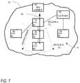
- FIG. 7illustrates a second operational mode in which a detection system is used to detect the presence of a GPS denial device in an area of interest
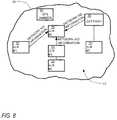
- FIG. 8illustrates a third operational mode in which a detection system is used to detect the presence or direction of a GPS denial device, in an area of interest, utilizing network assistance in calculating GPS parameters;
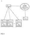
- FIG. 9is a block diagram of a GPS denial system in accordance with another alternative preferred embodiment of the present invention.
- FIG. 10is a block diagram of an exemplary denial RSI for use in the system of FIG. 9 ;
- FIG. 11is a block diagram of an exemplary gateway for use in the system of FIG. 9 ;
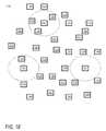
- FIG. 12illustrates a fourth operational mode in which a GPS denier system is used to control selected GPS denier RSIs;
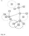
- FIGS. 13 and 14are block diagrams of a combined GPS detection/denial management system in accordance with another preferred embodiment of the present invention.
- FIGS. 15-18illustrate an exemplary seventh operational mode in which a combined GPS detection/denial management system is deployed and utilized as a tactical measure.
- any sequence(s) and/or temporal order of steps of various processes or methods that are described hereinare illustrative and not restrictive. Accordingly, it should be understood that, although steps of various processes or methods may be shown and described as being in a sequence or temporal order, the steps of any such processes or methods are not limited to being carried out in any particular sequence or order, absent an indication otherwise. Indeed, the steps in such processes or methods generally may be carried out in various different sequences and orders while still falling within the scope of the present invention. Accordingly, it is intended that the scope of patent protection afforded the present invention is to be defined by the appended claims rather than the description set forth herein.
- a picnic basket having an appledescribes “a picnic basket having at least one apple” as well as “a picnic basket having apples.”
- a picnic basket having a single appledescribes “a picnic basket having only one apple.”
- FIG. 1is a block diagram of a GPS denier detection system 10 in accordance with a preferred embodiment of the present invention.
- the detection system 10comprises a plurality of remote sensor interfaces, each of which includes a GPS receiver integral therewith (each a “GPS-RSI”) 20 , at least one gateway 40 , an external network 16 and a computer management system 14 .
- GPS-RSIs 20 and the gateway 40each comprise a communication node in one or more ad hoc wireless networks, some of which are described further hereinbelow.
- the computer management system 14primarily includes a server, and although different computer management system arrangements may be utilized, all arrangements will generally be referred to hereinafter as a “server.” Further, as shown in the detection system 110 of FIG. 2 , the server 14 may be physically co-located with the gateway 40 , thereby foregoing the need for an external network connecting the gateway 40 to the server 14 .
- the combination of a gateway 40 with a server 14 in a unitary componentis sometimes referred to as a “gateway controller.”
- a GPS-RSI 20is diagrammatically shown to include: a Wake-Up Receiver 22 for receiving wireless signals, a GPS receiver 24 for calculating the position of the GPS-RSI 20 and thus the position of the individual or equipment carrying the GPS-RSI 20 , a standards based radio 26 for two-way wireless communications with, for example, one or more other GPS-RSIs 20 and/or one or more gateways 40 , and an electrical power source 28 , such as a battery.
- the GPS receiver 24is incorporated directly into the GPS-RSI 20 , and as such a separate interface between the respective devices is not illustrated.
- a GPS receiver 24may be physically separated from, but associated with, the other portions of a GPS-RSI 20 , thereby providing generally similar functionality to the arrangement depicted in FIGS. 1 and 2 . Such an arrangement is shown in the detection system 210 of FIG. 4 .
- the GPS receiver 24 and the other portions of the GPS-RSI 20may be contained in separate housings, and electronic communication between the GPS receiver 24 and the other portions of the GPS-RSI 20 are exchanged wirelessly in some embodiments of the invention and by way of a cabled connection in other embodiments.
- the GPS-RSI 20may further include a sensor interface 30 for acquiring data from one or more sensors associated with the GPS-RSI 20 .
- the GPS-RSI 20is associated with military equipment and personnel assets, such individual soldiers, operational units or vehicles or other equipment carrying or supporting personnel or equipment
- the GPS-RSI 20preferably is capable of interfacing with sensors that, for example, monitor the assets, environmental characteristics of the assets, and/or geographical locations of the assets.
- sensorsmay actually be included within the GPS-RSI 20 ; in other embodiments, such sensors may be external to the GPS-RSI 20 but nevertheless disposed in electronic communication with the sensor interface for data exchange therebetween.
- the sensor interfacecomprises a multi-conductor connector, such as a ribbon cable, that passes from the interior of an GPS-RSI 20 and to an external sensor, sensor array, or docking station that receives the GPS-RSI 20 .
- exemplary sensorsinclude, but are not limited to, electronic seals, magnetic seals, cameras, microphones, temperature sensors, humidity sensors, radiation sensors, and motion sensors.
- the standards based radio 26which has a relatively high power consumption rate when active, is generally dormant until awakened.
- the Wake-Up Receiver 22which has a relatively low power consumption rate compared to that of the standards based radio 26 , generally remains active for detecting incoming wireless wake-up signals.
- the Wake-Up Receiver 22Upon receipt of a wake-up signal intended for the GPS-RSI 20 , the Wake-Up Receiver 22 generally wakes-up the standards based radio 26 for receiving and transmitting data via the standards based radio 26 .
- Those components of the GPS-RSI 20 that consume relatively high amounts of power therebyare generally active only when needed.
- the Wake-up Receiver 22includes components for receiving wireless wake-up signals.
- the Wake-Up Receiver 22is generally similar in function to the “WT Component” described in detail, for example, in incorporated International Patent Application Publication No. WO 03/098851 A1 (and which international application entered the U.S. national phase and published as U.S. Patent Application Publication No. US 2005/0215280, also incorporated herein by reference).
- the Wake-Up Receiver 22moreover has been occasionally referred to as a “tag turn-on circuit,” a “TTOC” or a “Wake-Up Rx.”
- the process for determining whether to wake-up the standards based radio of the GPS-RSI 20furthermore may include a number of steps that are performed in a particular sequence, especially if the GPS-RSI 20 is disposed in a noisy radio-frequency (RF) environment.
- RFradio-frequency
- Reduction in unnecessary power consumptionmay also be achieved by utilizing common designation ad hoc networks such as, for example, class-based networks.
- Common designation networkingis disclosed, for example, in U.S. patent application Ser. No. 11/161,539, which published as U.S. Patent Application Publication No. 2006/0023678 A1, each of which is hereby incorporated herein by reference.
- a gateway 40may include: a Wake-Up Transmitter 42 for transmitting wireless signals, a standards based radio 26 for two-way wireless communications with one or more GPS-RSIs 20 and/or one or more other gateways 40 , and an electrical power source 48 , such as a battery.
- the gateway 40may also include a GPS receiver 24 for calculating the position of the gateway 40 and/or a sensor interface 30 for acquiring data from one or more sensors associated with the gateway 40 .
- the Wake-Up Transmitter 42includes components for transmitting wireless wake-up signals.
- the Wake-Up Transmitter 42has occasionally been referred to as a “tag turn-on,” a “TTO” or a “Wake-Up Tx,” and the Wake-Up Transmitter 42 is capable of sending signals to Wake-Up Receivers 22 , TTOCs, or the like, for wake-up of GPS-RSIs 20 .
- a gatewaymay include a Wake-Up Receiver 22 like those included in the GPS-RSIs 20 , either in place of or in addition to the Wake-Up Transmitter.
- the Wake-Up Transmitteris further capable of sending signals to gateways 40 .
- the gateway 40facilitates communication between one or more wireless networks, formed using the gateway 40 and one or more of the GPS-RSIs 20 as communication nodes, and the external network 16 .
- the gateway 40further includes one or more appropriate connections for communicating with such an external network 16 , such connection including but not limited to a network interface for mobile phone, WiFi, two-way radio, secure radio links, Ethernet, and/or satellite communications.
- Each gateway 40thus serves as an access point for communications with the external network 16 .
- Electronic communication between the network interface and the external network 16may be exchanged wirelessly in some embodiments of the invention and by way of a cabled connection in other embodiments.
- the external network 16may include wired or wireless communications using any of the foregoing technologies or combination thereof, as well as any other appropriate communication technologies. Additionally, the external network 16 may incorporate use of the Internet or some other wide area network.
- the GPS-RSIs 20are programmed to communicate directly with the gateway 40 or to communicate via hopping. Because the GPS-RSIs 20 can hop between one another to reach a gateway 40 , fewer gateways 40 are needed to cover an area.
- the gateway 40communicates with the server 14 , which is disposed on and/or connected to the external network 16 .
- the server 14is responsible for numerous functions in detecting the presence of a GPS denial device. For example, as described below, the server 14 extracts GPS parameters from each GPS-RSI 20 and compares such extracted parameters with historical parameters. The server 14 also acts as an application interface and provides control for the GPS receivers 24 and any other sensors communicatively connected to a GPS-RSI 20 via sensor interface 30 .
- the present inventionrelates to use of such components in implementations involving GPS denier detection and/or selective GPS jamming.
- the system of FIG. 1has the ability to determine or detect whether a GPS denial device is present so that it can be identified and knocked out by military action and has the ability to find a GPS denial device based on the effect that it is having on multiple GPS receivers disposed in a particular area.
- An RSI with an associated GPS receiveris relatively inexpensive and may be housed within a relatively small form factor. Accordingly, such RSI-GPS receiver combinations may be deployed on a large scale due to the relatively low expense and size of the combination. Further, the small size renders the combination relatively inconspicuous and easily disguisable, which is particularly advantageous in military applications.
- FIGS. 6-9are block diagrams of detector systems in accordance with multiple preferred operational modes of a system of the present invention.
- FIG. 6illustrates a first operational mode in which a detection system 10 is used to detect the presence of a GPS denial device 60 in an area of interest 50 .
- the detection system 10once again comprises a plurality of GPS-RSIs 20 , a gateway 40 , an external network (not shown) and a server (not shown).
- the GPS-RSIs 20 and the gateway 40are the communication nodes of an ad hoc wireless network.
- the system of FIG. 6is able to detect the presence of the GPS denial device 60 as follows.
- the GPS receivers 24accept GPS radio signals from GPS satellites (not shown). Based on such signals, the GPS receivers 24 determine positional parameters such as latitude, longitude, and altitude. GPS receivers 24 may also determine, or be used to determine, parameters such as signal velocity, signal strength, satellites in view, and various other information related to received GPS radio signals.
- a microprocessor or the like (not shown) in each GPS-RSI 20extracts the available parameters from the GPS receiver 24 associated therewith and the GPS-RSI 20 uses its standards based radio 26 to communicate the parameters to the server 14 via the gateway 40 and external network 16 .
- GPS-RSI 20is unable to communicate directly with the gateway 40 , conventional hopping techniques may be used to communicate the parameters to the gateway 40 via one or more intermediate GPS-RSIs 20 .
- a software applicationstores the parameters in an appropriate location and format for later retrieval and examination.
- GPS parameter datais preferably gathered on a regular basis, with the frequency being selected on the basis of one or more factors, such as accuracy, speed, bandwidth, data capacity, and the like.
- GPS parameter datais gathered at a frequency controlled by the server 14 using the Wake-Up Transmitters 42 and Wake-Up Receivers 22 to awaken the various GPS-RSIs 20 as desired. More specifically, when the server 14 (or the software application being executed thereon) determines that it is time to receive GPS parameter data from the GPS receiver 24 of a GPS-RSI 20 , the server 14 may control one or more gateways 40 to transmit, via their respective Wake-Up Transmitters 42 , a wake-up signal appropriate to awaken the GPS-RSI 20 .
- Such signalsmay be tailored to awaken a particular GPS-RSI 20 , all GPS-RSIs 20 in a wireless network, or any subset thereof, as desired.
- the Wake-Up Receiver 22 of the GPS-RSI 20Upon receiving such a wake-up signal, the Wake-Up Receiver 22 of the GPS-RSI 20 causes the GPS receiver 24 and the standards based radio 26 to awaken, and the GPS receiver 24 is set into listening mode. After a sufficient duration has passed for the GPS receiver 24 to gather radio signal information, the desired parameters are read out of the GPS receiver 24 and transmitted by the standards based radio 26 for relay back to the server 14 for analysis.
- the gateway 40is equipped with its own GPS receiver 24 , then GPS parameters from the gateway GPS receiver 24 may likewise be gathered and relayed back to the server 14 . In this regard, it may be desirable for the gateway 40 to be likewise equipped with a Wake-Up Receiver 22 in order to conserve power or to simplify operation of the system 10 .
- a GPS-RSI 20 or gateway 40can also awaken the GPS-RSIs 20 .
- other devicessuch as a real-time clocks, or sensor triggers such as those based on motion, temperature, or humidity and optionally gathered via the sensor interface 30 .
- radio standby time and receive mode currentsno longer drive battery requirements. Further, battery power is actually conserved because the GPS-RSI 20 has the ability to enable event-driven monitoring of GPS receivers 24 .
- Parameters extracted from the receivers 24 at any particular timecan be compared to previously extracted, historical parameters, which are stored at the server, to deduce whether a jammer 60 is present. More specifically, algorithms may be used to determine when newly-received GPS parameter data is likely corrupted by the operation of a nearby GPS denial device 60 . If the server 14 determines that a GPS denial device 60 appears to be present in the vicinity of a GPS-RSI 20 , appropriate information may be relayed back to the GPS-RSI 20 , to one or more other GPS-RSIs 20 , to other nearby equipment (not shown), or in any other way appropriate for notifying the equipment and/or a user as to the presence of a GPS denial device 60 operating nearby. In addition, or alternatively, appropriate information may be relayed to unrelated personnel or equipment in any location. For example, in military operations, if a GPS denial device 60 is discovered, it may be desirable to order an air strike targeting the GPS denial device 60 .
- FIG. 7illustrates a second operational mode in which a detection system 10 is used to detect the direction of a GPS denial device 60 in an area of interest 50 .
- the detection system 10once again comprises a plurality of GPS-RSIs 20 , a gateway 40 , an external network (not shown) and a server (not shown), and as shown, the GPS-RSIs 20 and the gateway 40 are the communication nodes of an ad hoc wireless network.
- GPS denial devices 60tend to be directional, so information about the status of GPS receivers 24 and their relative positions can be used to determine the location of a GPS denial device 60 . More particularly, the difficulty encountered by the GPS receiver 24 in calculating an accurate position may be used as a rough indicator of the proximity of a GPS denial device 60 . For example, if the server 14 determines, based on a comparison of current GPS parameter data to historical GPS parameter data, that a GPS receiver 24 is denied or prevented from calculating a position altogether, the likelihood of a GPS denial device 60 being relatively near that GPS-RSI 20 is high. If the server 14 determines that a GPS receiver 24 is able to calculate a partial position or a position close to its previously-determined, historical, position, the GPS receiver 24 is likely farther away from the GPS denial device 60 .
- FIG. 7illustrates a first region (“Region A”) 52 , defined generally as a region in which GPS receivers 24 is denied or prevented from calculating a position altogether, and a second region (“Region B”) 54 , defined generally as a region in which GPS receivers 24 are able to calculate at least a partial position but for which the calculation is adversely affected by a GPS denial device 60 .
- the GPS-RSI 20 labeled “G-R # 2 ”is shown to be disposed in Region A 52
- the GPS-RSIs 20 labeled “G-R # 3 ” and “G-R # 4 ”are shown to be disposed in Region B 54 .
- the general direction of a GPS denial device 60may be visualized by drawing an imaginary arrow 56 starting from a GPS receiver 24 with a partially erroneous position (such as “G-R # 3 ” and “G-R # 4 ”) and drawn through to a GPS receiver 24 (such as “G-R # 2 ”) that is denied a position calculation altogether.
- Such an arrow 56points generally in the direction of the GPS denial device 60 .
- Other GPS parameterscan be studied to determine likely proximity of a GPS receiver 24 relative to a GPS denial device 60 , thereby providing a distance estimate in addition to a directional estimate. Similar techniques can be used if the radio receiver is something other than a GPS receiver 24 .
- FIG. 8illustrates a third operational mode in which a detection system 10 is used to detect the presence or direction of a GPS denial device 60 , in an area of interest 50 , utilizing network assistance in calculating GPS parameters.
- a detection system 10is used to detect the presence or direction of a GPS denial device 60 , in an area of interest 50 , utilizing network assistance in calculating GPS parameters.
- Such an operational modemay be useful in certain environments, such as urban environments, jungle canopy, mountainous regions and high multi-path environments, in which standard GPS receivers 24 frequently have difficulty generating accurate GPS parameters independently.
- the detection system 10once again comprises a plurality of GPS-RSIs 20 , a gateway 40 , an external network (not shown) and a server (not shown), and as shown, the GPS-RSIs 20 and the gateway 40 are the communication nodes of an ad hoc wireless network.
- Pertinent informationsuch as Ephemeris, Almanac, GPS time, approximate location, satellites that should be in view, and the like is determined by a GPS receiver 24 known to be reliable, such as a GPS receiver 24 located at a gateway 40 known to be uncompromised and uncorrupted, and/or provided by the server 14 .
- the information thus developedis then downloaded from the gateway 40 to the GPS-RSI 20 that is encountering difficulty in determining GPS parameters accurately.
- the GPS receiver 24may then be able to calculate its position and other GPS parameters accurately without relying solely on the GPS radio signals it receives from the GPS system. If so, then the GPS parameters may be relayed back to the server 14 as described previously, and using the newly-calculated GPS parameters as historic data, the GPS receiver 24 may then be restarted to determine the effects, if any, of a GPS denial device 60 .
- FIG. 9is a block diagram of a GPS denial system 70 in accordance with a preferred embodiment of the present invention.
- the detection system 70comprises a plurality of remote sensor interfaces, each of which includes a GPS denier 84 integral therewith (each a “denial RSI”) 80 , at least one gateway 90 , an external network 16 and a computer management system 14 .
- the denial RSIs 80 and the gateway 90each comprise a communication node in one or more ad hoc wireless networks, some of which are described further hereinbelow.
- the computer management system or server 14 and external network 16may be similar to those of FIG. 1 , described above, except that the computer management system (again referred to generally as a “server”) 14 has different or additional functionality as described below. Also, as with the system 10 of FIG. 1 , the server 14 may be physically co-located with the gateway 90 , thereby foregoing the need for the external network, and the combination of a gateway 90 with a server 14 in a unitary component is sometimes referred to as a “gateway controller.”
- a denial RSI 80is diagrammatically shown to include: a Wake-Up Receiver 22 for receiving wireless signals, a GPS denier 84 for jamming enemy GPS receivers (not shown), a standards based radio 26 for two-way wireless communications with, for example, one or more other denial RSIs 80 and/or one or more gateways 90 , and an electrical power source 28 , such as a battery.
- the GPS denier 84is incorporated directly into the denial RSI 80 , and as such a separate interface between the respective devices is not illustrated.
- a GPS denier 84alternatively may be physically separated from, but associated with, the other portions of a denial RSI 80 , thereby providing generally similar functionality to the arrangement depicted in FIG. 10 .
- the GPS denier 84 and the other portions of the denial RSI 80may be contained in separate housings, and electronic communication between the GPS denier 84 and the other portions of the denial RSI 80 are exchanged wirelessly in some embodiments of the invention and by way of a cabled connection in other embodiments.
- the denial RSI 80may further include a sensor interface 30 for acquiring data from one or more sensors associated with the denial RSI 80 .
- the sensor interface 30is similar to, and provides similar functionality as, the sensor interface 30 of the GPS-RSI 20 .
- the standards based radio 26 and Wake-Up Receiver 22are also similar to those of the GPS-RSI 20 , and like the GPS-RSI 20 , reduction in unnecessary power consumption may also be achieved by utilizing common designation ad hoc networks such as, for example, class-based networks.
- a gateway 90may include: a Wake-Up Transmitter 42 for transmitting wireless signals, a standards based radio 26 for two-way wireless communications with one or more denial RSIs 80 and/or one or more other gateways 90 , and an electrical power source 48 , such as a battery.
- the gateway 90may also include a GPS denier 84 for jamming enemy GPS receivers and/or a sensor interface 30 for acquiring data from one or more sensors associated with the gateway 90 .
- the components of the gateway 90may be generally similar to the corresponding components of the gateway 40 of FIG. 5 .
- the gateway 90 of FIG. 11facilitates communication between one or more wireless networks, in this case formed using the gateway 90 and one or more of the denial RSIs 80 as communication nodes, and the external network 16 .
- the gateway 90once again further includes one or more appropriate connections for communicating with such an external network 16 , such connection including but not limited to a network interface for mobile phone, WiFi, two-way radio, secure radio links, Ethernet, and/or satellite communications.
- each gateway 90thus serves as an access point for communications with the external network 16 .
- Electronic communication between the network interface and the external network 16may once again be exchanged wirelessly in some embodiments of the invention and by way of a cabled connection in other embodiments.
- the denial RSIs 80are programmed to communicate directly with the gateway 90 or to communicate via hopping. Because the denial RSIs 80 can hop between one another to reach a gateway 90 , fewer gateways 90 are needed to cover an area.
- the gateway 90communicates with the server 14 , which in at least one embodiment is disposed on and/or connected to the external network 16 , and in at least another embodiment is physically co-located with the gateway 90 as stated previously.
- the server 14is responsible for numerous functions in controlling the operation of the GPS deniers 84 .
- the server 14may send messages or signals to the gateway 90 , or to the denial RSIs 80 via the gateway 90 , to activate or deactivate one or more of the respective GPS deniers 84 .
- common designation networksmay be utilized to control one GPS denier 84 or gateway 90 , all the GPS deniers 84 and gateways 90 , or any subset thereof.
- the server 14may also track location information about the respective denial RSIs 80 and/or gateway 90 , thereby facilitating the localized use of the respective GPS deniers 84 as desired.
- GPS parametersmay be used to track the location of the denial RSIs 80 and gateway 90 .
- GPS parametersmay be developed, for example, but not limited to, through the use of GPS receivers located at or near the denial RSIs 80 and/or gateway 90 .
- GPS receiverssuch as the GPS receivers 24 described above may be associated with the respective denial RSIs 80 as described hereinbelow.
- FIG. 12illustrates a fourth operational mode in which a GPS denier system 70 is used to control selected denier RSIs 80 so as to create a corridor of reliable GPS operation, in an area of interest 50 , that is free from the effects of friendly GPS deniers 84 .
- the detection system 70once again comprises a plurality of denier RSIs 80 , a gateway 90 , an external network (not shown) and a server (not shown), and as shown, the denier RSIs 80 and the gateway 90 are the communication nodes of an ad hoc wireless network.
- the denier RSIs 80 labeled “DENIER-RSI # 1 ” and “DENIER-RSI # 5 ”are shown to have active GPS deniers 84 , while the remaining denier RSIs 80 are shown in thave inactive GPS deniers 84 .
- a corridor of reliable GPS operationis shown to exist in the region between the respective ranges of operation of “DENIER-RSI # 1 ” and “DENIER-RSI # 5 .”
- Localized GPS denialis thus provided in the regions around “DENIER-RSI # 1 ” and “DENIER-RSI # 5 ” while troop movement, such as in the direction of the arrows 58 , is permitted through the corridor, without GPS receivers carried by such troops being affected by those deniers 84 .
- the selection of particular denial RSIs 80 to be activated or deactivatedmay be controlled by the server 14 , and the locations of the denial RSIs 80 are preferably tracked by the server 14 so as to provide useful locational information to friendly parties as appropriate.
- a GPS detection system 20 and a GPS denier system 70may be combined in a single GPS detection and denial management system 110 , as represented in FIGS. 13-17 .
- a system 110may make use of combined GPS detection/denial RSIs 120 and/or combined GPS detection/denial-equipped gateways 140 .
- Combined GPS detection/denial RSIs 120include both a GPS receiver 24 and a GPS denier 84 , as those components are described previously, and combined GPS detection/denial-equipped gateways 140 likewise include both a GPS receiver 24 and a GPS denier 84 , wherein the respective GPS receiver 24 and a GPS denier 84 may be operated independently, preferably under the control of a server 14 .
- such a system 110may include multiple gateways 40 , 90 , 140 , each of which may be connected to the server 14 via an external network 16 .
- FIGS. 13 and 14are block diagrams of a combined GPS detection/denial management system 120 in accordance with another preferred embodiment of the present invention. More particularly, FIG. 13 illustrates a fifth operational mode in which GPS-equipped RSIs 20 , 120 and GPS-equipped gateways 40 , 140 form ad hoc wireless networks that are separate from ad hoc wireless networks formed by GPS denier-equipped RSIs 80 , 120 and GPS denier-equipped gateways 90 , 140 , while FIG.
- FIG. 14illustrates a sixth operational mode in which ad hoc wireless networks are formed that include GPS-equipped RSIs 20 , 120 , GPS denier-equipped RSIs 80 , 120 , GPS-equipped gateways 40 , 140 and GPS denier-equipped gateways 90 , 140 .
- each operational modeit is assumed that one or more enemy GPS denial devices 60 are operating in the vicinity of the system 120 .
- the combined GPS detection/denial-equipped gateway 140 and a first of the GPS denier-equipped RSIs 80have been activated
- FIG. 14the combined GPS detection/denial-equipped gateway 140 and the first GPS denier-equipped RSI 80 have been deactivated
- a second GPS denier-equipped RSI 80 and the combined GPS detection/denial RSI 120have been activated.
- the fifth and sixth operational modesare merely variations of the same operational mode, wherein the types of devices that are included in a particular ad hoc network may be controlled using different designations in a common designation ad hoc network, as described previously.
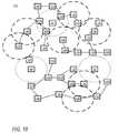
- FIGS. 15-18illustrate an exemplary seventh operational mode in which a combined GPS detection/denial management system 120 is deployed and utilized as a tactical measure.
- a deployment methodologymay be utilized, for example, when it is desired to search an area of interest for enemy GPS denial devices 60 for the purpose of identification and possible tactical measures against the GPS denial devices 60 , or when it has already been established that such devices 60 are operating and additional identification and possible tactical measures are desired.
- gatewayssuch as combined GPS detection/denial-equipped gateways 140 , may be set up in the area of interest, or, if available, pre-existing gateways may be utilized.
- GPS-equipped RSIswhich are preferably combined GPS detection/denial RSIs 120 , are deployed in the area of interest. Deployment may be achieved via air drop, by land vehicle, by personnel traveling on foot, or by any combination thereof. Pre-existing RSIs, including any combination of RSI devices 20 , 80 , 120 , may likewise be utilized.
- each of the GPS-equipped RSIs 120may be activated (if not previously activated) via one or more ad hoc wireless networks, as shown in FIG. 17 , and GPS parameters from the various GPS receivers 24 , in both the RSIs 120 and the gateways 140 , may be transmitted back to the gateways 140 .
- the GPS parametersare then communicated via the external network to the server (not shown).
- hoppingmay be used to transmit the GPS parameters from more remotely-located RSIs 120 back to the various gateways 140 . If deployment has been successful, some of the GPS-equipped RSIs 120 are within range of the enemy GPS denial devices 60 , while others are located out of range of such devices 60 .
- the server 14assesses all of the GPS parameter data, determining which RSIs 120 and which gateways 140 are within the vicinity of a GPS denial device 60 and where such GPS denial devices 60 are likely to be located. Such determinations may be accomplished using the techniques described hereinabove, including vicinity assessment, direction assessment, and network-aided correction and assessment.
- the server 14is preferably capable of accumulating and combining all information thus developed. Further, the server 14 may provide various graphical user interfaces (“GUIs”) and/or other user interfaces (“UIs”) that may assist user in locating the GPS denial devices 60 and tactical planning with regard an appropriate response to such GPS denial devices 60 . As described previously, the server 14 may also provide appropriate information back to one or more of the RSIs 120 , gateways 140 , and/or other personnel, equipment, and the like.
- GUIsgraphical user interfaces
- UIsuser interfaces
- an appropriate tactical responsemay likewise be developed. As shown in FIG. 18 , some of the GPS deniers 84 may be activated, while others remain deactivated. Selection of GPS deniers 84 to be activated may be based on the tactical response chosen for dealing with the enemy GPS denial devices 60 .
- the tactical responsemay include operations intended to destroy one or more enemy GPS denial devices 60 , to disrupt operation of one or more enemy GPS denial devices 60 using electronic techniques and the like, or other tactical strategies.
- An example of an electronic techniqueis the use of conventional signal cancellation techniques, where a signal that is an exact inversion of a jamming signal produced by an enemy GPS denial device 60 is transmitted, thereby effectively destroying the jamming signal.
- the GPS deniers 84 that are activatedmay be selected in order to achieve tightly-controlled corridors between the zones of coverage of both enemy and friendly GPS denial devices 60 , 84 .
- Such a corridor or regionis illustrated in FIG. 18 , extending from the lower left corner of the area of interest into the center of the area, and further extending from the center of the area toward the right-hand side of the area. GPS receivers in the corridor may accurately make position determinations.
- the corridorthus permits free movement or operation, using reliable GPS determinations, as part of a direct tactical response to the enemy GPS denial devices 60 as well as unrelated movement or operation by friendly forces.
- multiple GPS deniers 84may be deployed with associated RSIs to create a patchwork of GPS deniers 84 to fit situational needs.
- precise deployment and control of GPS deniers 84allows defined areas to be selected for jamming without having to deny GPS access to a larger area.
- GPS receivers 24can be replaced with any radio receiver to determine the jamming effects on a receiver in an “area of interest”. Parameters from each of these receivers 24 may be different, but the comparison of the parameters by the associated server 14 enables the system 110 to determine the extent of the jamming.
- the present inventionalso provides benefits such as the ability to determine the type of GPS denial device 60 so that corrections can be made in the actual position, and improved sensitivity and diversity making detection of GPS denial devices 60 more robust.
- the techniques described hereinmay also be used to measure the effectiveness of actions to remove known GPS denial devices 60 .
- a system 110such as that of FIGS. 15-18 can be utilized to repeatedly search an area of interest for adversarial GPS denial devices 60 after one or more tactical actions have been taken.
- This stepcan measure the effectiveness of the tactical operation by determining whether or not the adversarial GPS denial devices 60 are still in operation.
- the stepcan also be help identify the presence and location of additional GPS denial devices 60 that had not been previously detected.
- any of the gateways 40 , 90 , 140 described hereinmay also or alternatively be carried on an airborne platform, such as an Unmanned Aerial Vehicle (UAV), airship, airplane, or the like.
- UAVUnmanned Aerial Vehicle
- the gateway 40 , 90 , 140would communicate to the various RSIs 20 , 80 , 120 or land-based gateways 40 , 90 , 140 via wireless LAN (Local Area Network) and communicate over a satellite back to a remote server 14 .
- a gateway controller(comprised of a gateway 40 , 90 , 140 and a server 14 ) can also be mounted on the aerial platform and potentially provide database updates remotely.
- At least some of the techniques described herein for locating enemy GPS denial devices 60may likewise be utilized to identify monitor regions in which GPS reception is affected by friendly GPS deniers 84 , to provide feedback regarding the effects of friendly GPS denial attempts, and the like.
Landscapes
- Engineering & Computer Science (AREA)
- Radar, Positioning & Navigation (AREA)
- Remote Sensing (AREA)
- Computer Networks & Wireless Communication (AREA)
- Physics & Mathematics (AREA)
- General Physics & Mathematics (AREA)
- Computer Security & Cryptography (AREA)
- Position Fixing By Use Of Radio Waves (AREA)
Abstract
Description
Claims (12)
Priority Applications (8)
| Application Number | Priority Date | Filing Date | Title |
|---|---|---|---|
| US11/424,847US7583769B2 (en) | 2005-06-16 | 2006-06-16 | Operating GPS receivers in GPS-adverse environment |
| US12/168,195US20080304443A1 (en) | 2000-12-22 | 2008-07-07 | Standards based communictions for a container security system |
| US12/202,247US20090016308A1 (en) | 2000-12-22 | 2008-08-30 | Antenna in cargo container monitoring and security system |
| US12/346,448US7733944B2 (en) | 2005-06-16 | 2008-12-30 | Operating GPS receivers in GPS-adverse environment |
| US12/473,264US8218514B2 (en) | 2000-12-22 | 2009-05-27 | Wireless data communications network system for tracking containers |
| US12/556,538US8280345B2 (en) | 2000-12-22 | 2009-09-09 | LPRF device wake up using wireless tag |
| US12/774,589US20100214060A1 (en) | 2000-12-22 | 2010-05-05 | Wireless data communications network system for tracking containers |
| US12/780,823US8078139B2 (en) | 2000-12-22 | 2010-05-14 | Wireless data communications network system for tracking container |
Applications Claiming Priority (2)
| Application Number | Priority Date | Filing Date | Title |
|---|---|---|---|
| US59523305P | 2005-06-16 | 2005-06-16 | |
| US11/424,847US7583769B2 (en) | 2005-06-16 | 2006-06-16 | Operating GPS receivers in GPS-adverse environment |
Related Parent Applications (1)
| Application Number | Title | Priority Date | Filing Date |
|---|---|---|---|
| US11/424,849Continuation-In-PartUS7574168B2 (en) | 2000-12-22 | 2006-06-16 | Selective GPS denial system |
Related Child Applications (3)
| Application Number | Title | Priority Date | Filing Date |
|---|---|---|---|
| US11/424,845Continuation-In-PartUS7574300B2 (en) | 2000-12-22 | 2006-06-16 | GPS denial device detection and location system |
| US12/140,253Continuation-In-PartUS20080303897A1 (en) | 2000-12-22 | 2008-06-16 | Visually capturing and monitoring contents and events of cargo container |
| US12/346,448ContinuationUS7733944B2 (en) | 2005-06-16 | 2008-12-30 | Operating GPS receivers in GPS-adverse environment |
Publications (2)
| Publication Number | Publication Date |
|---|---|
| US20070001898A1 US20070001898A1 (en) | 2007-01-04 |
| US7583769B2true US7583769B2 (en) | 2009-09-01 |
Family
ID=37588795
Family Applications (2)
| Application Number | Title | Priority Date | Filing Date |
|---|---|---|---|
| US11/424,847Active2028-01-01US7583769B2 (en) | 2000-12-22 | 2006-06-16 | Operating GPS receivers in GPS-adverse environment |
| US12/346,448ActiveUS7733944B2 (en) | 2005-06-16 | 2008-12-30 | Operating GPS receivers in GPS-adverse environment |
Family Applications After (1)
| Application Number | Title | Priority Date | Filing Date |
|---|---|---|---|
| US12/346,448ActiveUS7733944B2 (en) | 2005-06-16 | 2008-12-30 | Operating GPS receivers in GPS-adverse environment |
Country Status (1)
| Country | Link |
|---|---|
| US (2) | US7583769B2 (en) |
Cited By (11)
| Publication number | Priority date | Publication date | Assignee | Title |
|---|---|---|---|---|
| US20110163914A1 (en)* | 2009-12-31 | 2011-07-07 | Seymour Leslie | Gps with aiding from ad-hoc peer-to-peer bluetooth networks |
| US9532310B2 (en) | 2008-12-25 | 2016-12-27 | Google Inc. | Receiver state estimation in a duty cycled radio |
| US9571986B2 (en) | 2014-05-07 | 2017-02-14 | Johnson Controls Technology Company | Systems and methods for detecting and using equipment location in a building management system |
| US9860839B2 (en) | 2004-05-27 | 2018-01-02 | Google Llc | Wireless transceiver |
| US9986484B2 (en) | 2005-07-01 | 2018-05-29 | Google Llc | Maintaining information facilitating deterministic network routing |
| US10481574B2 (en) | 2016-05-04 | 2019-11-19 | Johnson Controls Technology Company | Building alarm management system with mobile device notifications |
| US10664792B2 (en) | 2008-05-16 | 2020-05-26 | Google Llc | Maintaining information facilitating deterministic network routing |
| US10982868B2 (en) | 2015-05-04 | 2021-04-20 | Johnson Controls Technology Company | HVAC equipment having locating systems and methods |
| US20230003898A1 (en)* | 2021-06-30 | 2023-01-05 | Guangzhou Xiaopeng Autopilot Technology Co., Ltd. | System and method for global navigation satellite system (gnss) outlier detection and rejection and application of same |
| US11698461B1 (en) | 2019-11-20 | 2023-07-11 | Telephonics Corp. | GPS denial detection and reporting and mitigation |
| US11698462B1 (en)* | 2020-11-19 | 2023-07-11 | Flex Force Enterprises Inc. | Operational disruption of vehicle containing GNSS receiver |
Families Citing this family (31)
| Publication number | Priority date | Publication date | Assignee | Title |
|---|---|---|---|---|
| US7783246B2 (en) | 2005-06-16 | 2010-08-24 | Terahop Networks, Inc. | Tactical GPS denial and denial detection system |
| US7574168B2 (en) | 2005-06-16 | 2009-08-11 | Terahop Networks, Inc. | Selective GPS denial system |
| US7574300B2 (en) | 2005-06-16 | 2009-08-11 | Terahop Networks, Inc. | GPS denial device detection and location system |
| US7583769B2 (en) | 2005-06-16 | 2009-09-01 | Terahop Netowrks, Inc. | Operating GPS receivers in GPS-adverse environment |
| US7917409B1 (en)* | 2002-10-22 | 2011-03-29 | PPI Technology Services, LP | Method for monitoring and assembling equipment |
| CN1952602A (en)* | 2005-10-18 | 2007-04-25 | 国际商业机器公司 | Method and apparatus for determining the location of a user in an area |
| WO2007067831A1 (en) | 2005-10-31 | 2007-06-14 | Terahop Networks, Inc. | Determining relative elevation using gps and ranging |
| US7647071B2 (en)* | 2007-03-29 | 2010-01-12 | Broadcom Corporation | Communication devices with integrated gyrators and methods for use therewith |
| US8254847B2 (en)* | 2007-04-23 | 2012-08-28 | Department 13, LLC | Distributed wireless communications for tactical network dominance |
| US7894830B2 (en)* | 2007-04-28 | 2011-02-22 | Broadcom Corporation | Motion adaptive wireless local area network, wireless communications device and integrated circuits for use therewith |
| US8203451B2 (en)* | 2007-09-24 | 2012-06-19 | Savi Technology, Inc. | Method and apparatus for tracking and monitoring containers |
| US8643539B2 (en)* | 2008-11-19 | 2014-02-04 | Nokomis, Inc. | Advance manufacturing monitoring and diagnostic tool |
| KR101640208B1 (en)* | 2010-12-03 | 2016-07-18 | 한국전자통신연구원 | Apparatus and method for automatically generating parameters of a satellite operation procedure |
| US8630798B2 (en) | 2011-03-31 | 2014-01-14 | Motorola Mobility Llc | Electronic system and method for personal navigation |
| JP5358814B2 (en)* | 2011-05-31 | 2013-12-04 | トヨタ自動車株式会社 | Sensor information supplement system and sensor information supplement method |
| US11093722B2 (en) | 2011-12-05 | 2021-08-17 | Adasa Inc. | Holonomic RFID reader |
| US10476130B2 (en) | 2011-12-05 | 2019-11-12 | Adasa Inc. | Aerial inventory antenna |
| US10050330B2 (en) | 2011-12-05 | 2018-08-14 | Adasa Inc. | Aerial inventory antenna |
| US10846497B2 (en) | 2011-12-05 | 2020-11-24 | Adasa Inc. | Holonomic RFID reader |
| US9780435B2 (en) | 2011-12-05 | 2017-10-03 | Adasa Inc. | Aerial inventory antenna |
| US9747480B2 (en) | 2011-12-05 | 2017-08-29 | Adasa Inc. | RFID and robots for multichannel shopping |
| US9052387B2 (en)* | 2011-12-14 | 2015-06-09 | Lonestar Inventions, L.P. | Tamper resistant transponder with satellite link for airplane and ship safety |
| US8989922B2 (en)* | 2013-03-15 | 2015-03-24 | Azure Sky Group, LLC. | Modular drone and methods for use |
| EP3002610A3 (en)* | 2014-10-03 | 2016-06-22 | The Mitre Corporation | Detection of satellite system anomalies |
| US20170245361A1 (en)* | 2016-01-06 | 2017-08-24 | Nokomis, Inc. | Electronic device and methods to customize electronic device electromagnetic emissions |
| US10591609B1 (en) | 2017-01-11 | 2020-03-17 | Telephonics Corp. | System and method for providing accurate position location information to military forces in a disadvantaged signal environment |
| US10448864B1 (en) | 2017-02-24 | 2019-10-22 | Nokomis, Inc. | Apparatus and method to identify and measure gas concentrations |
| KR101866405B1 (en)* | 2017-11-27 | 2018-06-12 | 주식회사 포스트에피 | A Method of compressing data for Global Positioning System, a method of restoring the data for GPS and GPS device |
| US11489847B1 (en) | 2018-02-14 | 2022-11-01 | Nokomis, Inc. | System and method for physically detecting, identifying, and diagnosing medical electronic devices connectable to a network |
| GB2578922B (en) | 2018-11-14 | 2023-06-28 | Ge Aviat Systems Ltd | Detecting the spoofing of a signal |
| US11401033B2 (en)* | 2019-05-09 | 2022-08-02 | Noa, Inc. | Remote sensor data acquisition using autonomous drones |
Citations (200)
| Publication number | Priority date | Publication date | Assignee | Title |
|---|---|---|---|---|
| US3805265A (en) | 1971-10-06 | 1974-04-16 | Rcds Enterprises Inc | Radiant wave locating system |
| US4165024A (en) | 1977-09-09 | 1979-08-21 | Cato Oil And Grease Co. | Bulk shipping container |
| US4613990A (en) | 1984-06-25 | 1986-09-23 | At&T Bell Laboratories | Radiotelephone transmission power control |
| US4680583A (en) | 1985-01-30 | 1987-07-14 | Northern Telecom Limited | Terminal address assignment in a broadcast transmission system |
| US4688244A (en) | 1986-11-10 | 1987-08-18 | Marwan Hannon | Integrated cargo security system |
| US4750197A (en) | 1986-11-10 | 1988-06-07 | Denekamp Mark L | Integrated cargo security system |
| US4817537A (en) | 1987-03-16 | 1989-04-04 | Cripe Alan R | Container carrying convertible rail-highway vehicle |
| US5040238A (en) | 1990-06-29 | 1991-08-13 | Motorola, Inc. | Trunking system communication resource reuse method |
| US5054052A (en) | 1989-04-03 | 1991-10-01 | Mitsubishi Denki Kabushiki Kaisha | Mobile telephone device with low power consumption |
| EP0467036A2 (en) | 1990-06-15 | 1992-01-22 | Savi Technology, Inc. | Method and apparatus for radio identification and tracking |
| US5117501A (en) | 1988-08-08 | 1992-05-26 | General Electric Company | Dynamic regrouping in a trunked radio communications system |
| US5129096A (en) | 1989-05-12 | 1992-07-07 | Tunstall Telecom Limited | System which routes radio transmissions to selected repeaters for retransmission |
| US5210540A (en) | 1991-06-18 | 1993-05-11 | Pioneer Electronic Corporation | Global positioning system |
| US5265025A (en) | 1990-07-11 | 1993-11-23 | Mitsubishi Denki Kabushiki Kaisha | Navigation system using satellite signals |
| US5295154A (en) | 1991-10-01 | 1994-03-15 | Norand Corporation | Radio frequency local area network |
| US5331637A (en) | 1993-07-30 | 1994-07-19 | Bell Communications Research, Inc. | Multicast routing using core based trees |
| US5369784A (en) | 1991-08-01 | 1994-11-29 | City Communications Limited | Radio communications system using multiple simultaneously transmitting transceivers |
| US5400254A (en) | 1992-06-19 | 1995-03-21 | Sharp Kabushiki Kaisha | Trace display apparatus for a navigation system |
| US5425051A (en) | 1992-11-09 | 1995-06-13 | Norand Corporation | Radio frequency communication network having adaptive parameters |
| US5442758A (en) | 1993-07-19 | 1995-08-15 | Sequent Computer Systems, Inc. | Apparatus and method for achieving reduced overhead mutual exclusion and maintaining coherency in a multiprocessor system utilizing execution history and thread monitoring |
| US5511232A (en) | 1994-12-02 | 1996-04-23 | Motorola, Inc. | Method for providing autonomous radio talk group configuration |
| US5565858A (en) | 1994-09-14 | 1996-10-15 | Northrop Grumman Corporation | Electronic inventory system for stacked containers |
| US5579306A (en) | 1994-09-01 | 1996-11-26 | Ericsson Inc. | Time and frequency slot allocation system and method |
| US5590409A (en) | 1994-05-12 | 1996-12-31 | Ntt Mobile Communications Network Inc. | Transmission power control method and a transmission power control apparatus |
| US5596652A (en) | 1995-03-23 | 1997-01-21 | Portable Data Technologies, Inc. | System and method for accounting for personnel at a site and system and method for providing personnel with information about an emergency site |
| US5604892A (en) | 1992-09-01 | 1997-02-18 | Nuttall; David J. H. | Method for modeling a physical system of elements using a relational database |
| US5606313A (en) | 1993-12-10 | 1997-02-25 | Motorola, Inc. | Low power addressable data communication device and method |
| US5640151A (en) | 1990-06-15 | 1997-06-17 | Texas Instruments Incorporated | Communication system for communicating with tags |
| GB2308947A (en) | 1996-01-04 | 1997-07-09 | I D Systems Ltd | Identification tag with environmental sensing facility |
| US5652751A (en) | 1996-03-26 | 1997-07-29 | Hazeltine Corporation | Architecture for mobile radio networks with dynamically changing topology using virtual subnets |
| US5682379A (en) | 1993-12-23 | 1997-10-28 | Norand Corporation | Wireless personal local area network |
| US5732077A (en) | 1995-11-13 | 1998-03-24 | Lucent Technologies Inc. | Resource allocation system for wireless networks |
| US5761195A (en) | 1995-05-04 | 1998-06-02 | Interwave Communications International, Ltd. | Methods and apparatus for connecting calls in a hierarchical cellular network |
| US5790946A (en) | 1993-07-15 | 1998-08-04 | Rotzoll; Robert R. | Wake up device for a communications system |
| US5793882A (en) | 1995-03-23 | 1998-08-11 | Portable Data Technologies, Inc. | System and method for accounting for personnel at a site and system and method for providing personnel with information about an emergency site |
| US5833910A (en) | 1995-10-03 | 1998-11-10 | Mecanismos Auxiliares Industiales S.A. | Mold and method for manufacturing conduit grommet elements |
| US5862803A (en) | 1993-09-04 | 1999-01-26 | Besson; Marcus | Wireless medical diagnosis and monitoring equipment |
| US5890054A (en) | 1996-11-14 | 1999-03-30 | Telxon Corporation | Emergency mobile routing protocol |
| US5892441A (en) | 1996-06-26 | 1999-04-06 | Par Government Systems Corporation | Sensing with active electronic tags |
| US5907491A (en) | 1996-08-23 | 1999-05-25 | Csi Technology, Inc. | Wireless machine monitoring and communication system |
| US5917423A (en) | 1995-04-12 | 1999-06-29 | Lojack Corporation | Vehicles tracking transponder system and transponding method |
| US5939982A (en) | 1997-06-09 | 1999-08-17 | Auratek Security Inc. | Apparatus for monitoring opening of sealed containers |
| US5943610A (en) | 1996-04-05 | 1999-08-24 | Nec Corporation | Transmission power control with dynamic step values |
| US5950124A (en) | 1995-09-06 | 1999-09-07 | Telxon Corporation | Cellular communication system with dynamically modified data transmission parameters |
| US5951613A (en)* | 1996-10-23 | 1999-09-14 | Caterpillar Inc. | Apparatus and method for determining the position of a work implement |
| US5974236A (en) | 1992-03-25 | 1999-10-26 | Aes Corporation | Dynamically reconfigurable communications network and method |
| US5977913A (en) | 1997-02-07 | 1999-11-02 | Dominion Wireless | Method and apparatus for tracking and locating personnel |
| US6006100A (en) | 1990-05-25 | 1999-12-21 | Norand Corporation | Multi-level, hierarchical radio-frequency communication system |
| US6005884A (en) | 1995-11-06 | 1999-12-21 | Ems Technologies, Inc. | Distributed architecture for a wireless data communications system |
| US6072784A (en) | 1997-07-25 | 2000-06-06 | At&T Corp. | CDMA mobile station wireless transmission power management with adaptive scheduling priorities based on battery power level |
| US6078789A (en) | 1996-05-01 | 2000-06-20 | Bodenmann; Olivier | Wireless peripheral interface |
| US6091724A (en) | 1997-11-20 | 2000-07-18 | International Business Machines Corporation | Routing messages within a network using the data content of the message |
| US6097707A (en) | 1995-05-19 | 2000-08-01 | Hodzic; Migdat I. | Adaptive digital wireless communications network apparatus and process |
| US6104512A (en) | 1998-01-23 | 2000-08-15 | Motorola, Inc. | Method for adjusting the power level of an infrared signal |
| US6118988A (en) | 1998-03-02 | 2000-09-12 | Hyundai Electronics Industries Co., Ltd. | Transmission power control system and method for a mobile station |
| US6125306A (en) | 1995-10-13 | 2000-09-26 | Matsushita Electric Industrial Co., Ltd. | System for controlling physical distribution pallets |
| US6127976A (en) | 1998-09-03 | 2000-10-03 | Wherenet, Inc. | Distributed network for multi-lateration with circularly polarized antenna for hemispherical coverage |
| US6127928A (en) | 1998-02-10 | 2000-10-03 | E-Tag Systems, Inc. | Method and apparatus for locating and tracking documents and other objects |
| US6134587A (en) | 1996-12-27 | 2000-10-17 | Nec Corporation | Method of setting up ad hoc local area network, method of communicating using said network, and terminal for use with said network |
| WO2000068907A1 (en) | 1999-05-06 | 2000-11-16 | Pinpoint Corporation | An asset and personnel tagging system utilizing gps |
| WO2000069186A1 (en) | 1999-05-07 | 2000-11-16 | Telefonaktiebolaget Lm Ericsson (Publ) | A communication system |
| US6192400B1 (en) | 1990-05-25 | 2001-02-20 | Intermec Ip Corp. | Multilevel data communication system including local and host systems |
| US6198913B1 (en) | 1997-08-31 | 2001-03-06 | Samsung Electronics Co., Ltd. | Automatic wake-up device for radio automatic recognition terminal and communication method using the terminal |
| US6201974B1 (en) | 1996-09-06 | 2001-03-13 | Nokia Mobile Phones Limited | Mobile station and network having hierarchical index for cell broadcast service |
| US20010000019A1 (en) | 1997-07-24 | 2001-03-15 | Bowers John H. | Inventory system using articles with RFID tags |
| US6256303B1 (en) | 1999-10-15 | 2001-07-03 | Akoo, Inc. | Wireless broadcast link to remote receiver |
| US6313745B1 (en) | 2000-01-06 | 2001-11-06 | Fujitsu Limited | System and method for fitting room merchandise item recognition using wireless tag |
| US20010050550A1 (en) | 2000-02-29 | 2001-12-13 | Norio Yoshida | High frequency component, communication apparatus, and method for measuring characteristics of high frequency component |
| US6354493B1 (en) | 1999-12-23 | 2002-03-12 | Sensormatic Electronics Corporation | System and method for finding a specific RFID tagged article located in a plurality of RFID tagged articles |
| US6360169B1 (en) | 2000-09-07 | 2002-03-19 | Umesh Dudabey | System for determining and tracking changes in location |
| US20020039896A1 (en) | 2000-10-04 | 2002-04-04 | Brown Barry Allen Thomas | Method and apparatus for disabling mobile telephones |
| US6381467B1 (en) | 2000-06-22 | 2002-04-30 | Motorola, Inc. | Method and apparatus for managing an ad hoc wireless network |
| US20020050932A1 (en) | 2000-10-30 | 2002-05-02 | Ocean Systems Engineering Corporation | Environment and hazard condition monitoring system |
| US6405102B1 (en) | 1996-06-21 | 2002-06-11 | Symbol Technologies, Inc. | RF-interrogatable processing system |
| US6404082B1 (en) | 1999-09-24 | 2002-06-11 | Siemens Westinghouse Power Corporation | Exciter having thermally isolated diode wheel and method of removing diode wheel for same |
| US6409082B1 (en) | 1997-07-25 | 2002-06-25 | Perseu Administration (Proprietary) Limited | Tracking of products |
| US6418299B1 (en) | 1996-01-11 | 2002-07-09 | Bbn Corporation | Self-organizing mobile wireless station network |
| US20020089434A1 (en) | 2000-11-06 | 2002-07-11 | Ohanes Ghazarian | Electronic vehicle product and personnel monitoring |
| US6424264B1 (en) | 2000-10-12 | 2002-07-23 | Safetzone Technologies Corporation | System for real-time location of people in a fixed environment |
| US6424260B2 (en) | 1998-09-11 | 2002-07-23 | Key-Trak, Inc. | Mobile object tracking system |
| US20020098861A1 (en) | 2001-01-19 | 2002-07-25 | International Business Machines Corporation | Method and system for preventing wireless devices from interfering with other equipment in a sensitive area |
| US6427913B1 (en) | 1998-09-11 | 2002-08-06 | Key-Trak, Inc. | Object control and tracking system with zonal transition detection |
| US6437692B1 (en) | 1998-06-22 | 2002-08-20 | Statsignal Systems, Inc. | System and method for monitoring and controlling remote devices |
| US20020119770A1 (en) | 2000-12-22 | 2002-08-29 | Twitchell Robert W. | Class switched networks for tracking articles |
| US20020146985A1 (en) | 2001-01-31 | 2002-10-10 | Axonn Corporation | Battery operated remote transceiver (BORT) system and method |
| US6473607B1 (en) | 1998-06-01 | 2002-10-29 | Broadcom Corporation | Communication device with a self-calibrating sleep timer |
| US6476708B1 (en) | 1998-03-20 | 2002-11-05 | Hid Corporation | Detection of an RFID device by an RF reader unit operating in a reduced power state |
| US20030008692A1 (en) | 2001-07-05 | 2003-01-09 | Phelan John Roux | Energy conservation in battery powered tag |
| US6512478B1 (en) | 1999-12-22 | 2003-01-28 | Rockwell Technologies, Llc | Location position system for relay assisted tracking |
| US6529142B2 (en) | 2000-07-24 | 2003-03-04 | Shipong Norman Yeh | Parked vehicle location finder |
| US6542114B1 (en) | 2000-09-07 | 2003-04-01 | Savi Technology, Inc. | Method and apparatus for tracking items using dual frequency tags |
| US6547137B1 (en) | 2000-02-29 | 2003-04-15 | Larry J. Begelfer | System for distribution and control of merchandise |
| US20030083064A1 (en) | 2001-10-30 | 2003-05-01 | Rotem Cooper | Scheduling acquisition attempts of service providing systems |
| US6559620B2 (en) | 2001-03-21 | 2003-05-06 | Digital Angel Corporation | System and method for remote monitoring utilizing a rechargeable battery |
| EP1317733A2 (en) | 2000-09-07 | 2003-06-11 | Savi Technology, Inc. | Method and apparatus for tracking devices using tags |
| US6587755B1 (en) | 2000-07-12 | 2003-07-01 | International Business Machines Corporation | Virtual signs for improving information communicated to the automotive driver |
| US6600418B2 (en) | 2000-12-12 | 2003-07-29 | 3M Innovative Properties Company | Object tracking and management system and method using radio-frequency identification tags |
| US20030144020A1 (en) | 2002-01-31 | 2003-07-31 | Raghu Challa | Intermediate wake mode to track sleep clock frequency in a wireless communication device |
| US20030141973A1 (en) | 2001-07-24 | 2003-07-31 | Hen-Geul Yeh | Smart object locator |
| US6611556B1 (en) | 1999-05-21 | 2003-08-26 | Steve J. Koerner | Identification system for monitoring the presence/absence of members of a defined set |
| US6614349B1 (en) | 1999-12-03 | 2003-09-02 | Airbiquity Inc. | Facility and method for tracking physical assets |
| US6617962B1 (en) | 2000-01-06 | 2003-09-09 | Samsys Technologies Inc. | System for multi-standard RFID tags |
| US20030179073A1 (en) | 2002-03-20 | 2003-09-25 | Ohanes Ghazarian | Electronic secure locking system |
| US20030182077A1 (en) | 2002-03-25 | 2003-09-25 | Emord Nicholas Jon | Seamless sensory system |
| US20030209601A1 (en) | 2000-10-11 | 2003-11-13 | Chung Kevin Kwong-Tai | Article tracking system and method |
| WO2003098175A1 (en) | 2002-05-21 | 2003-11-27 | Intelligent Devices Inc. | Method for measuring temperature using a remote, passive, calibrated rf/rfid tag including a method for calibration |
| US6665585B2 (en) | 2000-01-31 | 2003-12-16 | Ishikarajima-Harima Jukogyo Kabushiki Kaisha | Method and apparatus for container management |
| US20030236077A1 (en) | 2002-04-10 | 2003-12-25 | Zarlink Semiconductor Ab | Method of saving power in communication devices |
| US20040021572A1 (en) | 2002-08-05 | 2004-02-05 | Schoen Marc L. | Electronic baggage tracking and identification |
| EP0748085B1 (en) | 1995-06-07 | 2004-02-11 | General Electric Company | Local communication network for power reduction and enhanced reliability in a multiple node tracking system |
| US6700533B1 (en) | 1999-05-06 | 2004-03-02 | Rf Technologies, Inc. | Asset and personnel tagging system utilizing GPS |
| US20040041731A1 (en) | 2002-08-29 | 2004-03-04 | Omron Corporation | Wireless node that uses a circular polarized antenna and a mechanism for preventing corner reflections of an inside of a metal box space |
| US6720888B2 (en) | 2000-09-07 | 2004-04-13 | Savi Technology, Inc. | Method and apparatus for tracking mobile devices using tags |
| US20040082296A1 (en) | 2000-12-22 | 2004-04-29 | Seekernet Incorporated | Network Formation in Asset-Tracking System Based on Asset Class |
| US6737974B2 (en) | 2001-09-18 | 2004-05-18 | Kent H. Dickinson | Shipping container and system along with shipping method employing the same |
| US20040100415A1 (en) | 2000-06-06 | 2004-05-27 | Veitch Jeffrey Douglas | Sample container with radiofrequency identifier tag |
| US20040100394A1 (en) | 2002-10-28 | 2004-05-27 | Hitt Dale K. | Distributed environmental control in a wireless sensor system |
| US6747562B2 (en) | 2001-11-13 | 2004-06-08 | Safetzone Technologies Corporation | Identification tag for real-time location of people |
| US6753775B2 (en) | 2002-08-27 | 2004-06-22 | Hi-G-Tek Ltd. | Smart container monitoring system |
| US20040119588A1 (en) | 2001-05-02 | 2004-06-24 | Marks Roger Julian | Door mountable alarm system |
| US20040121793A1 (en) | 2002-12-24 | 2004-06-24 | Weigele Ingo W. | Methods and apparatus for controlling power to electrical circuitry of a wireless communication device having a subscriber identity module (SIM) interface |
| US6761312B2 (en) | 1999-07-30 | 2004-07-13 | Salamander Technologies, Inc. | System and method for tracking victims of a mass casualty incident |
| US20040135691A1 (en) | 2003-01-13 | 2004-07-15 | Mark Duron | Package-integrated RF relay |
| US6765484B2 (en) | 2000-09-07 | 2004-07-20 | Savi Technology, Inc. | Method and apparatus for supplying commands to a tag |
| US20040183673A1 (en) | 2003-01-31 | 2004-09-23 | Nageli Hans Peter | Portable detachable self-contained tracking unit for two-way satellite communication with a central server |
| US6816063B2 (en) | 1999-01-29 | 2004-11-09 | Intermec Ip Corp | Radio frequency identification systems and methods for waking up data storage devices for wireless communication |
| US20040233041A1 (en) | 2001-03-27 | 2004-11-25 | Karl Bohman | Container surveillance system and related method |
| US20040233054A1 (en) | 2003-03-31 | 2004-11-25 | Neff Raymond Lynn | Wireless monitoring device |
| US20040232924A1 (en) | 2001-06-22 | 2004-11-25 | Hilleary Thomas N. | Methods and systems for automated pipeline testing |
| US20040246463A1 (en) | 2003-01-29 | 2004-12-09 | Milinusic Tomislav F. | Method and apparatus for optical inertial measurement |
| US6847892B2 (en) | 2001-10-29 | 2005-01-25 | Digital Angel Corporation | System for localizing and sensing objects and providing alerts |
| US20050073406A1 (en) | 2003-09-03 | 2005-04-07 | Easley Linda G. | System and method for providing container security |
| US20050087235A1 (en) | 2003-10-22 | 2005-04-28 | Skorpik James R. | Sensor assembly, system including RFID sensor assemblies, and method |
| US20050090211A1 (en) | 2003-10-28 | 2005-04-28 | Antti Lilja | Method and radio terminal equipment arrangement for power control, radio terminal equipment and secondary terminal unit |
| US20050088299A1 (en) | 2003-10-24 | 2005-04-28 | Bandy William R. | Radio frequency identification (RFID) based sensor networks |
| US20050093702A1 (en) | 2000-12-22 | 2005-05-05 | Twitchell Robert W.Jr. | Manufacture of LPRF device wake up using wireless tag |
| US20050093703A1 (en) | 2000-12-22 | 2005-05-05 | Twitchell Robert W.Jr. | Systems and methods having LPRF device wake up using wireless tag |
| EP0748083B1 (en) | 1995-06-07 | 2005-06-15 | General Electric Company | Use of mutter mode in asset tracking for gathering data from cargo sensors |
| US20050128080A1 (en) | 2003-02-21 | 2005-06-16 | Hall Larry L. | Cargo lock and monitoring apparatus and process |
| US20050145018A1 (en) | 2004-01-07 | 2005-07-07 | Ashok Sabata | Remote Monitoring of Pipelines using Wireless Sensor Network |
| US20050146445A1 (en) | 2003-12-31 | 2005-07-07 | Sleboda Pawel W. | Vehicle information display and communication system having an antenna array |
| US6919803B2 (en) | 2002-06-11 | 2005-07-19 | Intelligent Technologies International Inc. | Low power remote asset monitoring |
| US6927688B2 (en) | 2003-04-02 | 2005-08-09 | Caci International Inc. | Method for enabling communication and condition monitoring from inside of a sealed shipping container using impulse radio wireless techniques |
| US20050190759A1 (en) | 2004-02-28 | 2005-09-01 | Samsung Electronics Co., Ltd. | Method for transmitting a hello packet and a medium access control protocol layer module of a mobile station in a mobile ad hoc network |
| US6940392B2 (en) | 2001-04-24 | 2005-09-06 | Savi Technology, Inc. | Method and apparatus for varying signals transmitted by a tag |
| US20050199716A1 (en) | 2004-03-10 | 2005-09-15 | Microsoft Corporation | Method and system for communicating with identification tags |
| US20050215280A1 (en) | 2000-12-22 | 2005-09-29 | Twitchell Jr Robert W | Lprf device wake up using wireless tag |
| US20050226201A1 (en) | 1999-05-28 | 2005-10-13 | Afx Technology Group International, Inc. | Node-to node messaging transceiver network with dynamec routing and configuring |
| KR20050102419A (en) | 2004-04-22 | 2005-10-26 | 엘지전자 주식회사 | Wireless network system |
| US20050246133A9 (en)* | 2000-05-05 | 2005-11-03 | Bernd Mann | Control system or process for the automatic control of a moveable bucket wheel device |
| US20050261037A1 (en) | 2004-05-18 | 2005-11-24 | Raghunath Mandayam T | Conservation of battery power in mobile devices having communication capabilities |
| US20050270160A1 (en) | 2004-06-04 | 2005-12-08 | Maines Paper And Food Service, Inc. | Radio frequency device for tracking goods |
| US6975614B2 (en) | 2002-09-04 | 2005-12-13 | Harris Corporation | Intelligent communication node object beacon framework in a mobile ad hoc network |
| US20060022872A1 (en) | 2004-07-30 | 2006-02-02 | Integrinautics Corporation | Asynchronous local position determination system and method |
| US6999780B1 (en) | 2002-07-30 | 2006-02-14 | Bellsouth Intellectual Property Corporation | Method and system for determining the altitude of a mobile wireless device |
| US7012529B2 (en) | 2003-06-17 | 2006-03-14 | United Security Applications Id, Inc. | Electronic security system for monitoring and recording activity and data relating to cargo |
| US7027773B1 (en) | 1999-05-28 | 2006-04-11 | Afx Technology Group International, Inc. | On/off keying node-to-node messaging transceiver network with dynamic routing and configuring |
| US20060109106A1 (en) | 2004-11-22 | 2006-05-25 | Maersk Logistics Usa, Inc. | Shipping container monitoring and tracking system |
| US20060114102A1 (en) | 2004-11-26 | 2006-06-01 | Industrial Technology Research Institute | High performance RFID system and operating method thereof |
| US20060135145A1 (en) | 2004-12-17 | 2006-06-22 | Bbnt Solutions Llc | Methods and apparatus for reduced energy communication in an ad hoc network |
| US20060132485A1 (en)* | 2001-02-16 | 2006-06-22 | Milinusic Tomislav F | Surveillance management system |
| US20060163422A1 (en) | 2005-01-26 | 2006-07-27 | Raytheon Company | Pseudo GPS aided multiple projectile bistatic guidance |
| US20060164239A1 (en) | 2003-01-14 | 2006-07-27 | Loda David C | Shipping container and method of using same |
| US20060164232A1 (en) | 2003-04-09 | 2006-07-27 | Visible Assets, Inc. | Auditable security for cargo containers and other repositories |
| US7088229B2 (en) | 2004-06-14 | 2006-08-08 | Oracle International Corporation | Methods and systems for verifying the position and status of hierarchically arranged objects |
| EP1692599A2 (en) | 2003-12-08 | 2006-08-23 | Savi Technology, Inc. | Efficient aggregate summary views of massive numbers of items in highly concurrent update environments |
| EP1692668A2 (en) | 2003-12-09 | 2006-08-23 | Savi Technology, Inc. | Item-level visibility of nested and adjacent containers |
| US7103344B2 (en) | 2000-06-08 | 2006-09-05 | Menard Raymond J | Device with passive receiver |
| US7126470B2 (en) | 2004-03-31 | 2006-10-24 | Harris Corporation | Wireless ad-hoc RFID tracking system |
| US20060270382A1 (en) | 2002-10-22 | 2006-11-30 | Antti Lappetelainen | Method and device for transponder aided wake-up of a low power radio device |
| US20070001898A1 (en) | 2005-06-16 | 2007-01-04 | Terahop Networks, Inc. | operating gps receivers in gps-adverse environment |
| KR20070005515A (en) | 2005-07-06 | 2007-01-10 | 삼성전자주식회사 | Structure of a superframe transmitted in a wireless communication network, a method of transmitting the superframe, and a wake-up control method of a device through the superframe |
| US20070008408A1 (en) | 2005-06-22 | 2007-01-11 | Ron Zehavi | Wide area security system and method |
| US20070032951A1 (en) | 2005-04-19 | 2007-02-08 | Jaymart Sensors, Llc | Miniaturized Inertial Measurement Unit and Associated Methods |
| US20070040732A1 (en) | 2001-04-12 | 2007-02-22 | Garmin Ltd. | Device and method for calibrating and improving the accuracy of barometric altimeters with gps-derived altitudes |
| US7191934B2 (en) | 2003-07-21 | 2007-03-20 | Salamander Technologies, Inc. | Technique for creating incident-specific credentials at the scene of a large-scale incident or WMD event |
| US7196622B2 (en) | 2003-04-09 | 2007-03-27 | Savi Technology, Inc. | State monitoring of a container |
| US7200132B2 (en) | 2000-12-22 | 2007-04-03 | Terahop Networks, Inc. | Forming ad hoc RSI networks among transceivers sharing common designation |
| US7209468B2 (en) | 2000-12-22 | 2007-04-24 | Terahop Networks, Inc. | Forming communication cluster of wireless AD HOC network based on common designation |
| US7212122B2 (en) | 2003-12-30 | 2007-05-01 | G2 Microsystems Pty. Ltd. | Methods and apparatus of meshing and hierarchy establishment for tracking devices |
| US20070099629A1 (en) | 2005-10-31 | 2007-05-03 | Terahop Networks, Inc. | Using gps and ranging to determine relative elevation of an asset |
| US7221668B2 (en) | 2000-12-22 | 2007-05-22 | Terahop Networks, Inc. | Communications within population of wireless transceivers based on common designation |
| EP0829995B1 (en) | 1996-09-16 | 2007-05-23 | Sphere Communications Inc. | Lan telephone system |
| US7230933B2 (en) | 2002-04-17 | 2007-06-12 | Microsoft Corporation | Reducing idle power consumption in a networked battery operated device |
| US20070135179A1 (en) | 2000-07-26 | 2007-06-14 | Hardman Gordon E | System for conserving battery life in a battery operated device |
| US7233284B2 (en) | 2005-11-22 | 2007-06-19 | The United States Of America As Represented By The Secretary Of The Navy | Handheld GPS jammer locator |
| US7282944B2 (en) | 2003-07-25 | 2007-10-16 | Power Measurement, Ltd. | Body capacitance electric field powered device for high voltage lines |
| US7313421B2 (en) | 2004-09-28 | 2007-12-25 | G2 Microsystems Pty. Ltd. | GPS receiver having RF front end power management and simultaneous baseband searching of frequency and code chip offset |
| US7315281B2 (en) | 2004-07-30 | 2008-01-01 | G2 Microsystems Pty. Ltd. | Location determination method and system for asset tracking devices |
| US7319397B2 (en) | 2004-08-26 | 2008-01-15 | Avante International Technology, Inc. | RFID device for object monitoring, locating, and tracking |
| US7340260B2 (en) | 2002-10-09 | 2008-03-04 | Mdf Holdings, Inc. | System and method for tracking the location of multiple mobile radio transceiver units |
| US7349803B2 (en) | 2004-10-18 | 2008-03-25 | Trex Enterprises Corp. | Daytime stellar imager |
| US7349804B2 (en) | 2004-10-18 | 2008-03-25 | Trex Enterprises Corp. | Daytime stellar imager |
| US7348875B2 (en) | 2004-05-04 | 2008-03-25 | Battelle Memorial Institute | Semi-passive radio frequency identification (RFID) tag with active beacon |
| US20080096583A1 (en) | 2005-01-26 | 2008-04-24 | Broadcom Corporation | Gps enabled cell phone with common interest alerts |
| US7376507B1 (en) | 2004-05-27 | 2008-05-20 | Sandia Corporation | Geophysics-based method of locating a stationary earth object |
| US7391321B2 (en) | 2005-01-10 | 2008-06-24 | Terahop Networks, Inc. | Keyhole communication device for tracking and monitoring shipping container and contents thereof |
| US7440781B2 (en) | 2005-10-07 | 2008-10-21 | Symbol Technologies, Inc. | System and method for power conservation in a wireless device |
| US20080264888A1 (en)* | 2002-11-18 | 2008-10-30 | Mi-Jack Products, Inc. | Inventory storage and retrieval system and method with guidance for load-handling vehicle |
| US20080309550A1 (en) | 2004-10-21 | 2008-12-18 | Nokia Corporation | Satellite Based Positioning |
Family Cites Families (7)
| Publication number | Priority date | Publication date | Assignee | Title |
|---|---|---|---|---|
| US6717241B1 (en)* | 2000-08-31 | 2004-04-06 | Micron Technology, Inc. | Magnetic shielding for integrated circuits |
| US7783246B2 (en) | 2005-06-16 | 2010-08-24 | Terahop Networks, Inc. | Tactical GPS denial and denial detection system |
| US7542849B2 (en)* | 2005-06-03 | 2009-06-02 | Terahop Networks, Inc. | Network aided terrestrial triangulation using stars (NATTS) |
| US7574300B2 (en) | 2005-06-16 | 2009-08-11 | Terahop Networks, Inc. | GPS denial device detection and location system |
| US7574168B2 (en) | 2005-06-16 | 2009-08-11 | Terahop Networks, Inc. | Selective GPS denial system |
| US20050231425A1 (en)* | 2001-09-10 | 2005-10-20 | American Gnc Corporation | Wireless wide area networked precision geolocation |
| US20050114023A1 (en)* | 2003-11-26 | 2005-05-26 | Williamson Walton R. | Fault-tolerant system, apparatus and method |
- 2006
- 2006-06-16USUS11/424,847patent/US7583769B2/enactiveActive
- 2008
- 2008-12-30USUS12/346,448patent/US7733944B2/enactiveActive
Patent Citations (212)
| Publication number | Priority date | Publication date | Assignee | Title |
|---|---|---|---|---|
| US3805265A (en) | 1971-10-06 | 1974-04-16 | Rcds Enterprises Inc | Radiant wave locating system |
| US4165024A (en) | 1977-09-09 | 1979-08-21 | Cato Oil And Grease Co. | Bulk shipping container |
| US4613990A (en) | 1984-06-25 | 1986-09-23 | At&T Bell Laboratories | Radiotelephone transmission power control |
| US4680583A (en) | 1985-01-30 | 1987-07-14 | Northern Telecom Limited | Terminal address assignment in a broadcast transmission system |
| US4688244A (en) | 1986-11-10 | 1987-08-18 | Marwan Hannon | Integrated cargo security system |
| US4750197A (en) | 1986-11-10 | 1988-06-07 | Denekamp Mark L | Integrated cargo security system |
| US4817537A (en) | 1987-03-16 | 1989-04-04 | Cripe Alan R | Container carrying convertible rail-highway vehicle |
| US5117501A (en) | 1988-08-08 | 1992-05-26 | General Electric Company | Dynamic regrouping in a trunked radio communications system |
| US5054052A (en) | 1989-04-03 | 1991-10-01 | Mitsubishi Denki Kabushiki Kaisha | Mobile telephone device with low power consumption |
| US5129096A (en) | 1989-05-12 | 1992-07-07 | Tunstall Telecom Limited | System which routes radio transmissions to selected repeaters for retransmission |
| US6192400B1 (en) | 1990-05-25 | 2001-02-20 | Intermec Ip Corp. | Multilevel data communication system including local and host systems |
| US6006100A (en) | 1990-05-25 | 1999-12-21 | Norand Corporation | Multi-level, hierarchical radio-frequency communication system |
| US5640151A (en) | 1990-06-15 | 1997-06-17 | Texas Instruments Incorporated | Communication system for communicating with tags |
| EP0467036A2 (en) | 1990-06-15 | 1992-01-22 | Savi Technology, Inc. | Method and apparatus for radio identification and tracking |
| US5686902A (en) | 1990-06-15 | 1997-11-11 | Texas Instruments Incorporated | Communication system for communicating with tags |
| US5040238A (en) | 1990-06-29 | 1991-08-13 | Motorola, Inc. | Trunking system communication resource reuse method |
| US5265025A (en) | 1990-07-11 | 1993-11-23 | Mitsubishi Denki Kabushiki Kaisha | Navigation system using satellite signals |
| US5210540A (en) | 1991-06-18 | 1993-05-11 | Pioneer Electronic Corporation | Global positioning system |
| US5369784A (en) | 1991-08-01 | 1994-11-29 | City Communications Limited | Radio communications system using multiple simultaneously transmitting transceivers |
| US5295154A (en) | 1991-10-01 | 1994-03-15 | Norand Corporation | Radio frequency local area network |
| US5974236A (en) | 1992-03-25 | 1999-10-26 | Aes Corporation | Dynamically reconfigurable communications network and method |
| US5400254A (en) | 1992-06-19 | 1995-03-21 | Sharp Kabushiki Kaisha | Trace display apparatus for a navigation system |
| US5604892A (en) | 1992-09-01 | 1997-02-18 | Nuttall; David J. H. | Method for modeling a physical system of elements using a relational database |
| US5425051A (en) | 1992-11-09 | 1995-06-13 | Norand Corporation | Radio frequency communication network having adaptive parameters |
| US6760578B2 (en) | 1993-07-15 | 2004-07-06 | Micron Technology, Inc. | Wake up device for a communications system |
| US5790946A (en) | 1993-07-15 | 1998-08-04 | Rotzoll; Robert R. | Wake up device for a communications system |
| US5442758A (en) | 1993-07-19 | 1995-08-15 | Sequent Computer Systems, Inc. | Apparatus and method for achieving reduced overhead mutual exclusion and maintaining coherency in a multiprocessor system utilizing execution history and thread monitoring |
| US5331637A (en) | 1993-07-30 | 1994-07-19 | Bell Communications Research, Inc. | Multicast routing using core based trees |
| US5862803A (en) | 1993-09-04 | 1999-01-26 | Besson; Marcus | Wireless medical diagnosis and monitoring equipment |
| US5606313A (en) | 1993-12-10 | 1997-02-25 | Motorola, Inc. | Low power addressable data communication device and method |
| US5682379A (en) | 1993-12-23 | 1997-10-28 | Norand Corporation | Wireless personal local area network |
| US5590409A (en) | 1994-05-12 | 1996-12-31 | Ntt Mobile Communications Network Inc. | Transmission power control method and a transmission power control apparatus |
| US5579306A (en) | 1994-09-01 | 1996-11-26 | Ericsson Inc. | Time and frequency slot allocation system and method |
| US5565858A (en) | 1994-09-14 | 1996-10-15 | Northrop Grumman Corporation | Electronic inventory system for stacked containers |
| US5511232A (en) | 1994-12-02 | 1996-04-23 | Motorola, Inc. | Method for providing autonomous radio talk group configuration |
| US5596652A (en) | 1995-03-23 | 1997-01-21 | Portable Data Technologies, Inc. | System and method for accounting for personnel at a site and system and method for providing personnel with information about an emergency site |
| US5793882A (en) | 1995-03-23 | 1998-08-11 | Portable Data Technologies, Inc. | System and method for accounting for personnel at a site and system and method for providing personnel with information about an emergency site |
| US5917423A (en) | 1995-04-12 | 1999-06-29 | Lojack Corporation | Vehicles tracking transponder system and transponding method |
| US5761195A (en) | 1995-05-04 | 1998-06-02 | Interwave Communications International, Ltd. | Methods and apparatus for connecting calls in a hierarchical cellular network |
| US6097707A (en) | 1995-05-19 | 2000-08-01 | Hodzic; Migdat I. | Adaptive digital wireless communications network apparatus and process |
| EP0748083B1 (en) | 1995-06-07 | 2005-06-15 | General Electric Company | Use of mutter mode in asset tracking for gathering data from cargo sensors |
| EP0748085B1 (en) | 1995-06-07 | 2004-02-11 | General Electric Company | Local communication network for power reduction and enhanced reliability in a multiple node tracking system |
| US5950124A (en) | 1995-09-06 | 1999-09-07 | Telxon Corporation | Cellular communication system with dynamically modified data transmission parameters |
| US5833910A (en) | 1995-10-03 | 1998-11-10 | Mecanismos Auxiliares Industiales S.A. | Mold and method for manufacturing conduit grommet elements |
| US6125306A (en) | 1995-10-13 | 2000-09-26 | Matsushita Electric Industrial Co., Ltd. | System for controlling physical distribution pallets |
| US6005884A (en) | 1995-11-06 | 1999-12-21 | Ems Technologies, Inc. | Distributed architecture for a wireless data communications system |
| US5732077A (en) | 1995-11-13 | 1998-03-24 | Lucent Technologies Inc. | Resource allocation system for wireless networks |
| GB2308947A (en) | 1996-01-04 | 1997-07-09 | I D Systems Ltd | Identification tag with environmental sensing facility |
| US6418299B1 (en) | 1996-01-11 | 2002-07-09 | Bbn Corporation | Self-organizing mobile wireless station network |
| US5652751A (en) | 1996-03-26 | 1997-07-29 | Hazeltine Corporation | Architecture for mobile radio networks with dynamically changing topology using virtual subnets |
| US5943610A (en) | 1996-04-05 | 1999-08-24 | Nec Corporation | Transmission power control with dynamic step values |
| US6078789A (en) | 1996-05-01 | 2000-06-20 | Bodenmann; Olivier | Wireless peripheral interface |
| US6405102B1 (en) | 1996-06-21 | 2002-06-11 | Symbol Technologies, Inc. | RF-interrogatable processing system |
| US5892441A (en) | 1996-06-26 | 1999-04-06 | Par Government Systems Corporation | Sensing with active electronic tags |
| US5907491A (en) | 1996-08-23 | 1999-05-25 | Csi Technology, Inc. | Wireless machine monitoring and communication system |
| US6201974B1 (en) | 1996-09-06 | 2001-03-13 | Nokia Mobile Phones Limited | Mobile station and network having hierarchical index for cell broadcast service |
| EP0829995B1 (en) | 1996-09-16 | 2007-05-23 | Sphere Communications Inc. | Lan telephone system |
| US5951613A (en)* | 1996-10-23 | 1999-09-14 | Caterpillar Inc. | Apparatus and method for determining the position of a work implement |
| US5890054A (en) | 1996-11-14 | 1999-03-30 | Telxon Corporation | Emergency mobile routing protocol |
| US6134587A (en) | 1996-12-27 | 2000-10-17 | Nec Corporation | Method of setting up ad hoc local area network, method of communicating using said network, and terminal for use with said network |
| US5977913A (en) | 1997-02-07 | 1999-11-02 | Dominion Wireless | Method and apparatus for tracking and locating personnel |
| US5939982A (en) | 1997-06-09 | 1999-08-17 | Auratek Security Inc. | Apparatus for monitoring opening of sealed containers |
| US20010000019A1 (en) | 1997-07-24 | 2001-03-15 | Bowers John H. | Inventory system using articles with RFID tags |
| US6072784A (en) | 1997-07-25 | 2000-06-06 | At&T Corp. | CDMA mobile station wireless transmission power management with adaptive scheduling priorities based on battery power level |
| US6409082B1 (en) | 1997-07-25 | 2002-06-25 | Perseu Administration (Proprietary) Limited | Tracking of products |
| US6198913B1 (en) | 1997-08-31 | 2001-03-06 | Samsung Electronics Co., Ltd. | Automatic wake-up device for radio automatic recognition terminal and communication method using the terminal |
| US6091724A (en) | 1997-11-20 | 2000-07-18 | International Business Machines Corporation | Routing messages within a network using the data content of the message |
| US6104512A (en) | 1998-01-23 | 2000-08-15 | Motorola, Inc. | Method for adjusting the power level of an infrared signal |
| US6127928A (en) | 1998-02-10 | 2000-10-03 | E-Tag Systems, Inc. | Method and apparatus for locating and tracking documents and other objects |
| US6118988A (en) | 1998-03-02 | 2000-09-12 | Hyundai Electronics Industries Co., Ltd. | Transmission power control system and method for a mobile station |
| EP0944014B1 (en) | 1998-03-20 | 2005-12-28 | HID Corporation | Transponder system and method |
| US6476708B1 (en) | 1998-03-20 | 2002-11-05 | Hid Corporation | Detection of an RFID device by an RF reader unit operating in a reduced power state |
| US6473607B1 (en) | 1998-06-01 | 2002-10-29 | Broadcom Corporation | Communication device with a self-calibrating sleep timer |
| US20050043068A1 (en) | 1998-06-01 | 2005-02-24 | Aki Shohara | Communication device with a self-calibrating sleep timer |
| US6437692B1 (en) | 1998-06-22 | 2002-08-20 | Statsignal Systems, Inc. | System and method for monitoring and controlling remote devices |
| US6127976A (en) | 1998-09-03 | 2000-10-03 | Wherenet, Inc. | Distributed network for multi-lateration with circularly polarized antenna for hemispherical coverage |
| US6424260B2 (en) | 1998-09-11 | 2002-07-23 | Key-Trak, Inc. | Mobile object tracking system |
| US6427913B1 (en) | 1998-09-11 | 2002-08-06 | Key-Trak, Inc. | Object control and tracking system with zonal transition detection |
| US6816063B2 (en) | 1999-01-29 | 2004-11-09 | Intermec Ip Corp | Radio frequency identification systems and methods for waking up data storage devices for wireless communication |
| WO2000068907A1 (en) | 1999-05-06 | 2000-11-16 | Pinpoint Corporation | An asset and personnel tagging system utilizing gps |
| US6700533B1 (en) | 1999-05-06 | 2004-03-02 | Rf Technologies, Inc. | Asset and personnel tagging system utilizing GPS |
| WO2000069186A1 (en) | 1999-05-07 | 2000-11-16 | Telefonaktiebolaget Lm Ericsson (Publ) | A communication system |
| US6611556B1 (en) | 1999-05-21 | 2003-08-26 | Steve J. Koerner | Identification system for monitoring the presence/absence of members of a defined set |
| US20050226201A1 (en) | 1999-05-28 | 2005-10-13 | Afx Technology Group International, Inc. | Node-to node messaging transceiver network with dynamec routing and configuring |
| US7027773B1 (en) | 1999-05-28 | 2006-04-11 | Afx Technology Group International, Inc. | On/off keying node-to-node messaging transceiver network with dynamic routing and configuring |
| US6761312B2 (en) | 1999-07-30 | 2004-07-13 | Salamander Technologies, Inc. | System and method for tracking victims of a mass casualty incident |
| US6404082B1 (en) | 1999-09-24 | 2002-06-11 | Siemens Westinghouse Power Corporation | Exciter having thermally isolated diode wheel and method of removing diode wheel for same |
| US6256303B1 (en) | 1999-10-15 | 2001-07-03 | Akoo, Inc. | Wireless broadcast link to remote receiver |
| US6614349B1 (en) | 1999-12-03 | 2003-09-02 | Airbiquity Inc. | Facility and method for tracking physical assets |
| US6512478B1 (en) | 1999-12-22 | 2003-01-28 | Rockwell Technologies, Llc | Location position system for relay assisted tracking |
| US6354493B1 (en) | 1999-12-23 | 2002-03-12 | Sensormatic Electronics Corporation | System and method for finding a specific RFID tagged article located in a plurality of RFID tagged articles |
| US6313745B1 (en) | 2000-01-06 | 2001-11-06 | Fujitsu Limited | System and method for fitting room merchandise item recognition using wireless tag |
| US6617962B1 (en) | 2000-01-06 | 2003-09-09 | Samsys Technologies Inc. | System for multi-standard RFID tags |
| US6665585B2 (en) | 2000-01-31 | 2003-12-16 | Ishikarajima-Harima Jukogyo Kabushiki Kaisha | Method and apparatus for container management |
| US20010050550A1 (en) | 2000-02-29 | 2001-12-13 | Norio Yoshida | High frequency component, communication apparatus, and method for measuring characteristics of high frequency component |
| US6547137B1 (en) | 2000-02-29 | 2003-04-15 | Larry J. Begelfer | System for distribution and control of merchandise |
| US20050246133A9 (en)* | 2000-05-05 | 2005-11-03 | Bernd Mann | Control system or process for the automatic control of a moveable bucket wheel device |
| US20040100415A1 (en) | 2000-06-06 | 2004-05-27 | Veitch Jeffrey Douglas | Sample container with radiofrequency identifier tag |
| US7103344B2 (en) | 2000-06-08 | 2006-09-05 | Menard Raymond J | Device with passive receiver |
| US6381467B1 (en) | 2000-06-22 | 2002-04-30 | Motorola, Inc. | Method and apparatus for managing an ad hoc wireless network |
| US6587755B1 (en) | 2000-07-12 | 2003-07-01 | International Business Machines Corporation | Virtual signs for improving information communicated to the automotive driver |
| US6529142B2 (en) | 2000-07-24 | 2003-03-04 | Shipong Norman Yeh | Parked vehicle location finder |
| US20070135179A1 (en) | 2000-07-26 | 2007-06-14 | Hardman Gordon E | System for conserving battery life in a battery operated device |
| US6765484B2 (en) | 2000-09-07 | 2004-07-20 | Savi Technology, Inc. | Method and apparatus for supplying commands to a tag |
| EP1317733A2 (en) | 2000-09-07 | 2003-06-11 | Savi Technology, Inc. | Method and apparatus for tracking devices using tags |
| US6360169B1 (en) | 2000-09-07 | 2002-03-19 | Umesh Dudabey | System for determining and tracking changes in location |
| US6720888B2 (en) | 2000-09-07 | 2004-04-13 | Savi Technology, Inc. | Method and apparatus for tracking mobile devices using tags |
| US6542114B1 (en) | 2000-09-07 | 2003-04-01 | Savi Technology, Inc. | Method and apparatus for tracking items using dual frequency tags |
| US20020039896A1 (en) | 2000-10-04 | 2002-04-04 | Brown Barry Allen Thomas | Method and apparatus for disabling mobile telephones |
| US20030209601A1 (en) | 2000-10-11 | 2003-11-13 | Chung Kevin Kwong-Tai | Article tracking system and method |
| US6424264B1 (en) | 2000-10-12 | 2002-07-23 | Safetzone Technologies Corporation | System for real-time location of people in a fixed environment |
| US20020050932A1 (en) | 2000-10-30 | 2002-05-02 | Ocean Systems Engineering Corporation | Environment and hazard condition monitoring system |
| US20020089434A1 (en) | 2000-11-06 | 2002-07-11 | Ohanes Ghazarian | Electronic vehicle product and personnel monitoring |
| US6600418B2 (en) | 2000-12-12 | 2003-07-29 | 3M Innovative Properties Company | Object tracking and management system and method using radio-frequency identification tags |
| US7200132B2 (en) | 2000-12-22 | 2007-04-03 | Terahop Networks, Inc. | Forming ad hoc RSI networks among transceivers sharing common designation |
| US7209771B2 (en) | 2000-12-22 | 2007-04-24 | Terahop Networks, Inc. | Battery powered wireless transceiver having LPRF component and second wake up receiver |
| US7209468B2 (en) | 2000-12-22 | 2007-04-24 | Terahop Networks, Inc. | Forming communication cluster of wireless AD HOC network based on common designation |
| US7133704B2 (en) | 2000-12-22 | 2006-11-07 | Terahop Networks, Inc. | Manufacture of LPRF device wake up using wireless tag |
| US6745027B2 (en) | 2000-12-22 | 2004-06-01 | Seekernet Incorporated | Class switched networks for tracking articles |
| US7155264B2 (en) | 2000-12-22 | 2006-12-26 | Terahop Networks, Inc. | Systems and methods having LPRF device wake up using wireless tag |
| US20020119770A1 (en) | 2000-12-22 | 2002-08-29 | Twitchell Robert W. | Class switched networks for tracking articles |
| US20050093703A1 (en) | 2000-12-22 | 2005-05-05 | Twitchell Robert W.Jr. | Systems and methods having LPRF device wake up using wireless tag |
| US20050093702A1 (en) | 2000-12-22 | 2005-05-05 | Twitchell Robert W.Jr. | Manufacture of LPRF device wake up using wireless tag |
| US20040082296A1 (en) | 2000-12-22 | 2004-04-29 | Seekernet Incorporated | Network Formation in Asset-Tracking System Based on Asset Class |
| US6934540B2 (en) | 2000-12-22 | 2005-08-23 | Seekernet, Inc. | Network formation in asset-tracking system based on asset class |
| US7221668B2 (en) | 2000-12-22 | 2007-05-22 | Terahop Networks, Inc. | Communications within population of wireless transceivers based on common designation |
| US20050215280A1 (en) | 2000-12-22 | 2005-09-29 | Twitchell Jr Robert W | Lprf device wake up using wireless tag |
| US20020098861A1 (en) | 2001-01-19 | 2002-07-25 | International Business Machines Corporation | Method and system for preventing wireless devices from interfering with other equipment in a sensitive area |
| US20020146985A1 (en) | 2001-01-31 | 2002-10-10 | Axonn Corporation | Battery operated remote transceiver (BORT) system and method |
| US20060132485A1 (en)* | 2001-02-16 | 2006-06-22 | Milinusic Tomislav F | Surveillance management system |
| US6559620B2 (en) | 2001-03-21 | 2003-05-06 | Digital Angel Corporation | System and method for remote monitoring utilizing a rechargeable battery |
| US20040233041A1 (en) | 2001-03-27 | 2004-11-25 | Karl Bohman | Container surveillance system and related method |
| US20070040732A1 (en) | 2001-04-12 | 2007-02-22 | Garmin Ltd. | Device and method for calibrating and improving the accuracy of barometric altimeters with gps-derived altitudes |
| US6940392B2 (en) | 2001-04-24 | 2005-09-06 | Savi Technology, Inc. | Method and apparatus for varying signals transmitted by a tag |
| US20040119588A1 (en) | 2001-05-02 | 2004-06-24 | Marks Roger Julian | Door mountable alarm system |
| US20040232924A1 (en) | 2001-06-22 | 2004-11-25 | Hilleary Thomas N. | Methods and systems for automated pipeline testing |
| US20030008692A1 (en) | 2001-07-05 | 2003-01-09 | Phelan John Roux | Energy conservation in battery powered tag |
| US20030141973A1 (en) | 2001-07-24 | 2003-07-31 | Hen-Geul Yeh | Smart object locator |
| US6737974B2 (en) | 2001-09-18 | 2004-05-18 | Kent H. Dickinson | Shipping container and system along with shipping method employing the same |
| US6847892B2 (en) | 2001-10-29 | 2005-01-25 | Digital Angel Corporation | System for localizing and sensing objects and providing alerts |
| US20030083064A1 (en) | 2001-10-30 | 2003-05-01 | Rotem Cooper | Scheduling acquisition attempts of service providing systems |
| US6747562B2 (en) | 2001-11-13 | 2004-06-08 | Safetzone Technologies Corporation | Identification tag for real-time location of people |
| US20030144020A1 (en) | 2002-01-31 | 2003-07-31 | Raghu Challa | Intermediate wake mode to track sleep clock frequency in a wireless communication device |
| US20030179073A1 (en) | 2002-03-20 | 2003-09-25 | Ohanes Ghazarian | Electronic secure locking system |
| US20030182077A1 (en) | 2002-03-25 | 2003-09-25 | Emord Nicholas Jon | Seamless sensory system |
| US20030236077A1 (en) | 2002-04-10 | 2003-12-25 | Zarlink Semiconductor Ab | Method of saving power in communication devices |
| US7230933B2 (en) | 2002-04-17 | 2007-06-12 | Microsoft Corporation | Reducing idle power consumption in a networked battery operated device |
| WO2003098175A1 (en) | 2002-05-21 | 2003-11-27 | Intelligent Devices Inc. | Method for measuring temperature using a remote, passive, calibrated rf/rfid tag including a method for calibration |
| US6919803B2 (en) | 2002-06-11 | 2005-07-19 | Intelligent Technologies International Inc. | Low power remote asset monitoring |
| US6999780B1 (en) | 2002-07-30 | 2006-02-14 | Bellsouth Intellectual Property Corporation | Method and system for determining the altitude of a mobile wireless device |
| US20040021572A1 (en) | 2002-08-05 | 2004-02-05 | Schoen Marc L. | Electronic baggage tracking and identification |
| US6753775B2 (en) | 2002-08-27 | 2004-06-22 | Hi-G-Tek Ltd. | Smart container monitoring system |
| US20040041731A1 (en) | 2002-08-29 | 2004-03-04 | Omron Corporation | Wireless node that uses a circular polarized antenna and a mechanism for preventing corner reflections of an inside of a metal box space |
| US6975614B2 (en) | 2002-09-04 | 2005-12-13 | Harris Corporation | Intelligent communication node object beacon framework in a mobile ad hoc network |
| US7340260B2 (en) | 2002-10-09 | 2008-03-04 | Mdf Holdings, Inc. | System and method for tracking the location of multiple mobile radio transceiver units |
| US20060270382A1 (en) | 2002-10-22 | 2006-11-30 | Antti Lappetelainen | Method and device for transponder aided wake-up of a low power radio device |
| US20040100394A1 (en) | 2002-10-28 | 2004-05-27 | Hitt Dale K. | Distributed environmental control in a wireless sensor system |
| US20080264888A1 (en)* | 2002-11-18 | 2008-10-30 | Mi-Jack Products, Inc. | Inventory storage and retrieval system and method with guidance for load-handling vehicle |
| US20040121793A1 (en) | 2002-12-24 | 2004-06-24 | Weigele Ingo W. | Methods and apparatus for controlling power to electrical circuitry of a wireless communication device having a subscriber identity module (SIM) interface |
| US20040135691A1 (en) | 2003-01-13 | 2004-07-15 | Mark Duron | Package-integrated RF relay |
| US20060164239A1 (en) | 2003-01-14 | 2006-07-27 | Loda David C | Shipping container and method of using same |
| US20040246463A1 (en) | 2003-01-29 | 2004-12-09 | Milinusic Tomislav F. | Method and apparatus for optical inertial measurement |
| US20040183673A1 (en) | 2003-01-31 | 2004-09-23 | Nageli Hans Peter | Portable detachable self-contained tracking unit for two-way satellite communication with a central server |
| US20050128080A1 (en) | 2003-02-21 | 2005-06-16 | Hall Larry L. | Cargo lock and monitoring apparatus and process |
| US20040233054A1 (en) | 2003-03-31 | 2004-11-25 | Neff Raymond Lynn | Wireless monitoring device |
| US6927688B2 (en) | 2003-04-02 | 2005-08-09 | Caci International Inc. | Method for enabling communication and condition monitoring from inside of a sealed shipping container using impulse radio wireless techniques |
| US7196622B2 (en) | 2003-04-09 | 2007-03-27 | Savi Technology, Inc. | State monitoring of a container |
| US20060164232A1 (en) | 2003-04-09 | 2006-07-27 | Visible Assets, Inc. | Auditable security for cargo containers and other repositories |
| US7012529B2 (en) | 2003-06-17 | 2006-03-14 | United Security Applications Id, Inc. | Electronic security system for monitoring and recording activity and data relating to cargo |
| US7191934B2 (en) | 2003-07-21 | 2007-03-20 | Salamander Technologies, Inc. | Technique for creating incident-specific credentials at the scene of a large-scale incident or WMD event |
| US7282944B2 (en) | 2003-07-25 | 2007-10-16 | Power Measurement, Ltd. | Body capacitance electric field powered device for high voltage lines |
| US7098784B2 (en) | 2003-09-03 | 2006-08-29 | System Planning Corporation | System and method for providing container security |
| US20050073406A1 (en) | 2003-09-03 | 2005-04-07 | Easley Linda G. | System and method for providing container security |
| US20050087235A1 (en) | 2003-10-22 | 2005-04-28 | Skorpik James R. | Sensor assembly, system including RFID sensor assemblies, and method |
| US20050088299A1 (en) | 2003-10-24 | 2005-04-28 | Bandy William R. | Radio frequency identification (RFID) based sensor networks |
| US20050090211A1 (en) | 2003-10-28 | 2005-04-28 | Antti Lilja | Method and radio terminal equipment arrangement for power control, radio terminal equipment and secondary terminal unit |
| EP1692599A2 (en) | 2003-12-08 | 2006-08-23 | Savi Technology, Inc. | Efficient aggregate summary views of massive numbers of items in highly concurrent update environments |
| EP1692668A2 (en) | 2003-12-09 | 2006-08-23 | Savi Technology, Inc. | Item-level visibility of nested and adjacent containers |
| US7212122B2 (en) | 2003-12-30 | 2007-05-01 | G2 Microsystems Pty. Ltd. | Methods and apparatus of meshing and hierarchy establishment for tracking devices |
| US20050146445A1 (en) | 2003-12-31 | 2005-07-07 | Sleboda Pawel W. | Vehicle information display and communication system having an antenna array |
| US20050145018A1 (en) | 2004-01-07 | 2005-07-07 | Ashok Sabata | Remote Monitoring of Pipelines using Wireless Sensor Network |
| US20050190759A1 (en) | 2004-02-28 | 2005-09-01 | Samsung Electronics Co., Ltd. | Method for transmitting a hello packet and a medium access control protocol layer module of a mobile station in a mobile ad hoc network |
| US20050199716A1 (en) | 2004-03-10 | 2005-09-15 | Microsoft Corporation | Method and system for communicating with identification tags |
| US7126470B2 (en) | 2004-03-31 | 2006-10-24 | Harris Corporation | Wireless ad-hoc RFID tracking system |
| KR20050102419A (en) | 2004-04-22 | 2005-10-26 | 엘지전자 주식회사 | Wireless network system |
| US7348875B2 (en) | 2004-05-04 | 2008-03-25 | Battelle Memorial Institute | Semi-passive radio frequency identification (RFID) tag with active beacon |
| US20050261037A1 (en) | 2004-05-18 | 2005-11-24 | Raghunath Mandayam T | Conservation of battery power in mobile devices having communication capabilities |
| US7376507B1 (en) | 2004-05-27 | 2008-05-20 | Sandia Corporation | Geophysics-based method of locating a stationary earth object |
| US20050270160A1 (en) | 2004-06-04 | 2005-12-08 | Maines Paper And Food Service, Inc. | Radio frequency device for tracking goods |
| US7142121B2 (en) | 2004-06-04 | 2006-11-28 | Endicott Interconnect Technologies, Inc. | Radio frequency device for tracking goods |
| US7088229B2 (en) | 2004-06-14 | 2006-08-08 | Oracle International Corporation | Methods and systems for verifying the position and status of hierarchically arranged objects |
| US20060022872A1 (en) | 2004-07-30 | 2006-02-02 | Integrinautics Corporation | Asynchronous local position determination system and method |
| US7315281B2 (en) | 2004-07-30 | 2008-01-01 | G2 Microsystems Pty. Ltd. | Location determination method and system for asset tracking devices |
| US7319397B2 (en) | 2004-08-26 | 2008-01-15 | Avante International Technology, Inc. | RFID device for object monitoring, locating, and tracking |
| US7313421B2 (en) | 2004-09-28 | 2007-12-25 | G2 Microsystems Pty. Ltd. | GPS receiver having RF front end power management and simultaneous baseband searching of frequency and code chip offset |
| US7349803B2 (en) | 2004-10-18 | 2008-03-25 | Trex Enterprises Corp. | Daytime stellar imager |
| US7349804B2 (en) | 2004-10-18 | 2008-03-25 | Trex Enterprises Corp. | Daytime stellar imager |
| US20080309550A1 (en) | 2004-10-21 | 2008-12-18 | Nokia Corporation | Satellite Based Positioning |
| US20060109106A1 (en) | 2004-11-22 | 2006-05-25 | Maersk Logistics Usa, Inc. | Shipping container monitoring and tracking system |
| US20060114102A1 (en) | 2004-11-26 | 2006-06-01 | Industrial Technology Research Institute | High performance RFID system and operating method thereof |
| US20060135145A1 (en) | 2004-12-17 | 2006-06-22 | Bbnt Solutions Llc | Methods and apparatus for reduced energy communication in an ad hoc network |
| US7391321B2 (en) | 2005-01-10 | 2008-06-24 | Terahop Networks, Inc. | Keyhole communication device for tracking and monitoring shipping container and contents thereof |
| US20060163422A1 (en) | 2005-01-26 | 2006-07-27 | Raytheon Company | Pseudo GPS aided multiple projectile bistatic guidance |
| US20080096583A1 (en) | 2005-01-26 | 2008-04-24 | Broadcom Corporation | Gps enabled cell phone with common interest alerts |
| US20070032951A1 (en) | 2005-04-19 | 2007-02-08 | Jaymart Sensors, Llc | Miniaturized Inertial Measurement Unit and Associated Methods |
| US20070001898A1 (en) | 2005-06-16 | 2007-01-04 | Terahop Networks, Inc. | operating gps receivers in gps-adverse environment |
| US20070008408A1 (en) | 2005-06-22 | 2007-01-11 | Ron Zehavi | Wide area security system and method |
| KR20070005515A (en) | 2005-07-06 | 2007-01-10 | 삼성전자주식회사 | Structure of a superframe transmitted in a wireless communication network, a method of transmitting the superframe, and a wake-up control method of a device through the superframe |
| US7440781B2 (en) | 2005-10-07 | 2008-10-21 | Symbol Technologies, Inc. | System and method for power conservation in a wireless device |
| US20070099628A1 (en) | 2005-10-31 | 2007-05-03 | Terahop Networks, Inc. | Determining relative elevation using gps and ranging |
| US20070099629A1 (en) | 2005-10-31 | 2007-05-03 | Terahop Networks, Inc. | Using gps and ranging to determine relative elevation of an asset |
| US7233284B2 (en) | 2005-11-22 | 2007-06-19 | The United States Of America As Represented By The Secretary Of The Navy | Handheld GPS jammer locator |
Non-Patent Citations (23)
| Title |
|---|
| "Cluster Based Routing Protocol", Internet-Draft Mingliang, Jiang et al., National University of Singapore, Jul. 1999. |
| "Scalable Routing Strategies for Ad hoc Wireless Networks", Atsushi Iwata et al., IEEE Journal on Selected Areas in Communications, Special Issue on Adhoc Networks, Aug. 1999, pp. 1369-1379. |
| Atsushi Iwata, et al., Scalable Routing Strategies for Ad Hoc Wireless Networks, IEEE Journal on Selected Areas in Communications, vol. 17, No. 8, Aug. 1999, pp. 1369-1379. |
| Charles E. Perkins, Ad Hoc Networks, Jan. 2001, table of contents, chapters 1, 4, and 11. |
| Daniel Lihui Gu et al., C-ICAMA, A Centralized Intelligent Channel Assigned Multiple Access for Multi-Layer Ad-Hoc Wireless Networks with UAVs, 6 pages, 2000. |
| Daniel Lihui Gu et al., Hierarchical Routing for Multi-Layer Ad-Hoc Wireless Networks with UAV's, 5 pages, 2000. |
| Ezio Valdevit, Cascading in Fibre Channel: How to Build a Multi-Switch Fabric, pp. 1-12. |
| Gary Morgan, Miniature Tags Provide Visibility & Cohesion for an LIA Battalion Level 'Proof of Principle', Pacific NW National Laboratory, Apr. 2001, Gary.morgan@pnl.gov. |
| Guangyu Pei et al., Mobility Management in Hierarchical Multi-hop Mobile Wireless Networks, 6 pages, 1999. |
| Guangyu Pei, et al., A Wireless Hierarchical Routing Protocol with Group Mobility, 1998 IEEE, 5 pages. |
| http://www.cs.ucla.edu/NRL/wireless/PAPER/draft-ietf-manet-admrp-02.txt, Sung-Ju Lee et al., On-Demand Multicast Routing Protocol (ODMRP) for Ad Hoc Networks, Jan. 2000, visited Nov. 13, 2000. |
| http://www/iprg/nokia.com/charliep/txt/manet/term.txt, Mobile Ad Hoc Networking Terminology, C. Perkins, Nov. 17, 1998, visited Nov. 13, 2000. |
| J.J. Gardia-Luna-Aceves et al., Source-Tree Routing in Wireless Networks, 1999, 10 pages. |
| Jaap Haartsen et al., Bluetooth: Vision, Goals, and Architecture, Mobile Computing & Communications Review, vol. 1, No. 2, 1998, 8 pages. |
| Jaap Haartsen, Bluetooth-The Universal Radio Interface for Ad Hoc, Wireless Connectivity, Ericsson Review No. 3, pp. 110-117, 1998. |
| Jean-Pierre Hubaux et al., Toward Self-Organized Mobile Ad Hoc Networks: The Terminodes Project, IEEE Communications Magazine, Jan. 2001, pp. 118-124. |
| Keshavarzian et al., Energy-Efficient Link Assessment in Wireless Sensor Networks, INFOCOM 2004. 23rd Annual Joint Conference of the IEEE Computer and Communications Societies, vol. 3, 2004, pp. 1751-1761. |
| Kevin Sharp, Physical Reality: A Second Look, Supply Chain Systems, http://www.idsystems.com/reader/1999-03/phys0399-pt2/index.htm, Mar. 1999, Helmers Publishing, Inc. |
| Melodia et al., On the Interdependence of Distributed Topology Control and Geographical Routing in Ad Hoc and Sensor Networks, Selected Areas in Communications, IEEE Journal, vol. 23, Issue 3, Mar. 2005, pp. 520-532. |
| Ram Ramanathan et al., Hierarchically-Organized, Multihop Mobile Wireless Networks for Quality-of-Service Support, pp. 1-35, 1998. |
| Stojmenovic et al., Design Giudelines for Routing Protocols in Ad Hoc and Sensor Networks with a Realistic Physical Layer, Communications Magazine, IEEE, vol. 43, Issue 3, Mar. 2005, pp. 101-106. |
| U.S. Appl. No. 60/444,029, of Nageli, filed Jan. 31, 2003. |
| U.S. Appl. No. 60/499,338, of Easley et al., filed Sep. 3, 2003. |
Cited By (24)
| Publication number | Priority date | Publication date | Assignee | Title |
|---|---|---|---|---|
| US10861316B2 (en) | 2004-05-27 | 2020-12-08 | Google Llc | Relaying communications in a wireless sensor system |
| US10573166B2 (en) | 2004-05-27 | 2020-02-25 | Google Llc | Relaying communications in a wireless sensor system |
| US10565858B2 (en) | 2004-05-27 | 2020-02-18 | Google Llc | Wireless transceiver |
| US9860839B2 (en) | 2004-05-27 | 2018-01-02 | Google Llc | Wireless transceiver |
| US9955423B2 (en) | 2004-05-27 | 2018-04-24 | Google Llc | Measuring environmental conditions over a defined time period within a wireless sensor system |
| US10015743B2 (en) | 2004-05-27 | 2018-07-03 | Google Llc | Relaying communications in a wireless sensor system |
| US10229586B2 (en) | 2004-05-27 | 2019-03-12 | Google Llc | Relaying communications in a wireless sensor system |
| US10395513B2 (en) | 2004-05-27 | 2019-08-27 | Google Llc | Relaying communications in a wireless sensor system |
| US10425877B2 (en) | 2005-07-01 | 2019-09-24 | Google Llc | Maintaining information facilitating deterministic network routing |
| US10813030B2 (en) | 2005-07-01 | 2020-10-20 | Google Llc | Maintaining information facilitating deterministic network routing |
| US9986484B2 (en) | 2005-07-01 | 2018-05-29 | Google Llc | Maintaining information facilitating deterministic network routing |
| US11308440B2 (en) | 2008-05-16 | 2022-04-19 | Google Llc | Maintaining information facilitating deterministic network routing |
| US10664792B2 (en) | 2008-05-16 | 2020-05-26 | Google Llc | Maintaining information facilitating deterministic network routing |
| US9699736B2 (en) | 2008-12-25 | 2017-07-04 | Google Inc. | Reducing a number of wake-up frames in a sequence of wake-up frames |
| US9532310B2 (en) | 2008-12-25 | 2016-12-27 | Google Inc. | Receiver state estimation in a duty cycled radio |
| US20110163914A1 (en)* | 2009-12-31 | 2011-07-07 | Seymour Leslie | Gps with aiding from ad-hoc peer-to-peer bluetooth networks |
| US8884817B2 (en)* | 2009-12-31 | 2014-11-11 | CSR Technology Holdings Inc. | GPS with aiding from ad-hoc peer-to-peer bluetooth networks |
| US9571986B2 (en) | 2014-05-07 | 2017-02-14 | Johnson Controls Technology Company | Systems and methods for detecting and using equipment location in a building management system |
| US10982868B2 (en) | 2015-05-04 | 2021-04-20 | Johnson Controls Technology Company | HVAC equipment having locating systems and methods |
| US10481574B2 (en) | 2016-05-04 | 2019-11-19 | Johnson Controls Technology Company | Building alarm management system with mobile device notifications |
| US11698461B1 (en) | 2019-11-20 | 2023-07-11 | Telephonics Corp. | GPS denial detection and reporting and mitigation |
| US11698462B1 (en)* | 2020-11-19 | 2023-07-11 | Flex Force Enterprises Inc. | Operational disruption of vehicle containing GNSS receiver |
| US20230003898A1 (en)* | 2021-06-30 | 2023-01-05 | Guangzhou Xiaopeng Autopilot Technology Co., Ltd. | System and method for global navigation satellite system (gnss) outlier detection and rejection and application of same |
| US11624840B2 (en)* | 2021-06-30 | 2023-04-11 | Guangzhou Xiaopeng Autopilot Technology Co., Ltd. | System and method for global navigation satellite system (GNSS) outlier detection and rejection and application of same |
Also Published As
| Publication number | Publication date |
|---|---|
| US7733944B2 (en) | 2010-06-08 |
| US20090243924A1 (en) | 2009-10-01 |
| US20070001898A1 (en) | 2007-01-04 |
Similar Documents
| Publication | Publication Date | Title |
|---|---|---|
| US7783246B2 (en) | Tactical GPS denial and denial detection system | |
| US7583769B2 (en) | Operating GPS receivers in GPS-adverse environment | |
| US7574168B2 (en) | Selective GPS denial system | |
| US7574300B2 (en) | GPS denial device detection and location system | |
| US12032071B2 (en) | Satellite echoing for geolocation and mitigation of GNSS denial | |
| TW202142888A (en) | Determining correct location in the presence of gnss spoofing | |
| US11698462B1 (en) | Operational disruption of vehicle containing GNSS receiver | |
| US10302770B1 (en) | Systems and methods for absolute position navigation using pseudolites | |
| Mykytyn et al. | GPS-spoofing attack detection mechanism for UAV swarms | |
| EP3176607B1 (en) | Verification of trustworthiness of position information transmitted from an aircraft via a communications satellite | |
| Kozak et al. | The use of drones in military conflict | |
| WO2020226523A1 (en) | Method and system for jamming localization and supporting navigation system | |
| US12442932B2 (en) | System for local area detection and alerting of global navigation satellite system (GNSS) spoofing | |
| Carter et al. | Navigation Spoofing and ECD | |
| EP4307011A1 (en) | System for local area detection and alerting of global navigation satellite system (gnss) spoofing | |
| Janovec et al. | Analysis of available technologies for the design of a tracking device for monitoring endangered animal | |
| Lakshmi et al. | GPS Receiver Protection Requirement for Unmanned Aerial Vehicle | |
| Sugunaraj et al. | Navigational Dropouts in Small Unmanned Aerial Systems (sUAS)–A Short Review | |
| Agee | Resilient Distributed Positioning Networks: A New Approach to Extreme Low-Latency, High-Precision Positioning and Timing | |
| Nemeroff et al. | Networked sensor communications for the objective force | |
| Nichols | 19. Navigation Spoofing and ECD | |
| US20150199548A1 (en) | Method and Apparatus Involving Global Positioning and Long-Range Wireless Link |
Legal Events
| Date | Code | Title | Description |
|---|---|---|---|
| AS | Assignment | Owner name:TERAHOP NETWORKS, INC., GEORGIA Free format text:ASSIGNMENT OF ASSIGNORS INTEREST;ASSIGNORS:TWITCHELL, ROBERT W., JR.;SMITH, DELIA J.;SIGNING DATES FROM 20061128 TO 20070405;REEL/FRAME:019127/0132 Owner name:TERAHOP NETWORKS, INC., GEORGIA Free format text:ASSIGNMENT OF ASSIGNORS INTEREST;ASSIGNORS:TWITCHELL, ROBERT W., JR.;SMITH, DELIA J.;REEL/FRAME:019127/0132;SIGNING DATES FROM 20061128 TO 20070405 | |
| STCF | Information on status: patent grant | Free format text:PATENTED CASE | |
| AS | Assignment | Owner name:KLJ CONSULTING LLC, WASHINGTON Free format text:ASSIGNMENT OF ASSIGNORS INTEREST;ASSIGNOR:TERAHOP NETWORKS, INC.;REEL/FRAME:027422/0740 Effective date:20110916 | |
| AS | Assignment | Owner name:GOOGLE INC., CALIFORNIA Free format text:ASSIGNMENT OF ASSIGNORS INTEREST;ASSIGNOR:KLJ CONSULTING LLC;REEL/FRAME:028100/0701 Effective date:20120323 | |
| FEPP | Fee payment procedure | Free format text:PAT HOLDER NO LONGER CLAIMS SMALL ENTITY STATUS, ENTITY STATUS SET TO UNDISCOUNTED (ORIGINAL EVENT CODE: STOL); ENTITY STATUS OF PATENT OWNER: LARGE ENTITY | |
| FPAY | Fee payment | Year of fee payment:4 | |
| FPAY | Fee payment | Year of fee payment:8 | |
| AS | Assignment | Owner name:GOOGLE LLC, CALIFORNIA Free format text:CHANGE OF NAME;ASSIGNOR:GOOGLE INC.;REEL/FRAME:044101/0610 Effective date:20170929 | |
| MAFP | Maintenance fee payment | Free format text:PAYMENT OF MAINTENANCE FEE, 12TH YEAR, LARGE ENTITY (ORIGINAL EVENT CODE: M1553); ENTITY STATUS OF PATENT OWNER: LARGE ENTITY Year of fee payment:12 |