US7583762B2 - Reduced-complexity multiple-input, multiple-output detection - Google Patents
Reduced-complexity multiple-input, multiple-output detectionDownload PDFInfo
- Publication number
- US7583762B2 US7583762B2US10/990,910US99091004AUS7583762B2US 7583762 B2US7583762 B2US 7583762B2US 99091004 AUS99091004 AUS 99091004AUS 7583762 B2US7583762 B2US 7583762B2
- Authority
- US
- United States
- Prior art keywords
- values
- recited
- sequence
- scan
- metric
- Prior art date
- Legal status (The legal status is an assumption and is not a legal conclusion. Google has not performed a legal analysis and makes no representation as to the accuracy of the status listed.)
- Expired - Fee Related, expires
Links
- 238000001514detection methodMethods0.000titleabstractdescription9
- 238000000034methodMethods0.000claimsdescription26
- 238000012545processingMethods0.000claimsdescription7
- 230000000737periodic effectEffects0.000claims5
- 230000000295complement effectEffects0.000claims2
- 239000013598vectorSubstances0.000abstractdescription14
- 238000012360testing methodMethods0.000abstractdescription5
- 238000007476Maximum LikelihoodMethods0.000abstractdescription4
- 238000009825accumulationMethods0.000abstractdescription2
- 238000011156evaluationMethods0.000abstractdescription2
- 230000005540biological transmissionEffects0.000description10
- 230000008569processEffects0.000description7
- 238000004891communicationMethods0.000description6
- 239000011159matrix materialSubstances0.000description5
- 230000004044responseEffects0.000description4
- 230000008859changeEffects0.000description3
- 238000007792additionMethods0.000description2
- 238000013459approachMethods0.000description2
- 239000000969carrierSubstances0.000description2
- 238000013507mappingMethods0.000description2
- 239000000203mixtureSubstances0.000description2
- 238000012546transferMethods0.000description2
- 230000018199S phaseEffects0.000description1
- 239000000654additiveSubstances0.000description1
- 230000000996additive effectEffects0.000description1
- 230000015556catabolic processEffects0.000description1
- 238000012937correctionMethods0.000description1
- 238000006731degradation reactionMethods0.000description1
- 238000009795derivationMethods0.000description1
- 238000009429electrical wiringMethods0.000description1
- 230000005670electromagnetic radiationEffects0.000description1
- 239000000835fiberSubstances0.000description1
- 238000009472formulationMethods0.000description1
- 230000001788irregularEffects0.000description1
- 239000000463materialSubstances0.000description1
- 230000007246mechanismEffects0.000description1
- 230000010363phase shiftEffects0.000description1
- 238000007781pre-processingMethods0.000description1
- 230000000135prohibitive effectEffects0.000description1
- 238000000926separation methodMethods0.000description1
- 230000001629suppressionEffects0.000description1
Images


Classifications
- H—ELECTRICITY
- H04—ELECTRIC COMMUNICATION TECHNIQUE
- H04L—TRANSMISSION OF DIGITAL INFORMATION, e.g. TELEGRAPHIC COMMUNICATION
- H04L25/00—Baseband systems
- H04L25/02—Details ; arrangements for supplying electrical power along data transmission lines
- H04L25/03—Shaping networks in transmitter or receiver, e.g. adaptive shaping networks
- H04L25/03006—Arrangements for removing intersymbol interference
- H04L25/03178—Arrangements involving sequence estimation techniques
- H04L25/03184—Details concerning the metric
- H04L25/03191—Details concerning the metric in which the receiver makes a selection between different metrics
- H—ELECTRICITY
- H04—ELECTRIC COMMUNICATION TECHNIQUE
- H04L—TRANSMISSION OF DIGITAL INFORMATION, e.g. TELEGRAPHIC COMMUNICATION
- H04L25/00—Baseband systems
- H04L25/02—Details ; arrangements for supplying electrical power along data transmission lines
- H04L25/03—Shaping networks in transmitter or receiver, e.g. adaptive shaping networks
- H04L25/03006—Arrangements for removing intersymbol interference
- H04L25/03178—Arrangements involving sequence estimation techniques
- H04L25/03203—Trellis search techniques
- H04L25/0321—Sorting arrangements therefor
- H—ELECTRICITY
- H04—ELECTRIC COMMUNICATION TECHNIQUE
- H04L—TRANSMISSION OF DIGITAL INFORMATION, e.g. TELEGRAPHIC COMMUNICATION
- H04L25/00—Baseband systems
- H04L25/02—Details ; arrangements for supplying electrical power along data transmission lines
- H04L25/03—Shaping networks in transmitter or receiver, e.g. adaptive shaping networks
- H04L25/03006—Arrangements for removing intersymbol interference
- H04L25/03178—Arrangements involving sequence estimation techniques
- H04L25/03312—Arrangements specific to the provision of output signals
- H04L25/03318—Provision of soft decisions
- H—ELECTRICITY
- H04—ELECTRIC COMMUNICATION TECHNIQUE
- H04B—TRANSMISSION
- H04B7/00—Radio transmission systems, i.e. using radiation field
- H04B7/02—Diversity systems; Multi-antenna system, i.e. transmission or reception using multiple antennas
- H04B7/04—Diversity systems; Multi-antenna system, i.e. transmission or reception using multiple antennas using two or more spaced independent antennas
- H04B7/0413—MIMO systems
- H—ELECTRICITY
- H04—ELECTRIC COMMUNICATION TECHNIQUE
- H04L—TRANSMISSION OF DIGITAL INFORMATION, e.g. TELEGRAPHIC COMMUNICATION
- H04L25/00—Baseband systems
- H04L25/02—Details ; arrangements for supplying electrical power along data transmission lines
- H04L25/03—Shaping networks in transmitter or receiver, e.g. adaptive shaping networks
- H04L25/03006—Arrangements for removing intersymbol interference
- H04L2025/0335—Arrangements for removing intersymbol interference characterised by the type of transmission
- H04L2025/03375—Passband transmission
- H04L2025/03414—Multicarrier
- H—ELECTRICITY
- H04—ELECTRIC COMMUNICATION TECHNIQUE
- H04L—TRANSMISSION OF DIGITAL INFORMATION, e.g. TELEGRAPHIC COMMUNICATION
- H04L25/00—Baseband systems
- H04L25/02—Details ; arrangements for supplying electrical power along data transmission lines
- H04L25/03—Shaping networks in transmitter or receiver, e.g. adaptive shaping networks
- H04L25/03006—Arrangements for removing intersymbol interference
- H04L2025/0335—Arrangements for removing intersymbol interference characterised by the type of transmission
- H04L2025/03426—Arrangements for removing intersymbol interference characterised by the type of transmission transmission using multiple-input and multiple-output channels
- H—ELECTRICITY
- H04—ELECTRIC COMMUNICATION TECHNIQUE
- H04L—TRANSMISSION OF DIGITAL INFORMATION, e.g. TELEGRAPHIC COMMUNICATION
- H04L25/00—Baseband systems
- H04L25/02—Details ; arrangements for supplying electrical power along data transmission lines
- H04L25/03—Shaping networks in transmitter or receiver, e.g. adaptive shaping networks
- H04L25/03006—Arrangements for removing intersymbol interference
- H04L2025/03592—Adaptation methods
- H04L2025/03598—Algorithms
- H04L2025/03611—Iterative algorithms
- H04L2025/03643—Order recursive
- H—ELECTRICITY
- H04—ELECTRIC COMMUNICATION TECHNIQUE
- H04L—TRANSMISSION OF DIGITAL INFORMATION, e.g. TELEGRAPHIC COMMUNICATION
- H04L25/00—Baseband systems
- H04L25/02—Details ; arrangements for supplying electrical power along data transmission lines
- H04L25/0202—Channel estimation
- H04L25/0204—Channel estimation of multiple channels
- H—ELECTRICITY
- H04—ELECTRIC COMMUNICATION TECHNIQUE
- H04L—TRANSMISSION OF DIGITAL INFORMATION, e.g. TELEGRAPHIC COMMUNICATION
- H04L25/00—Baseband systems
- H04L25/02—Details ; arrangements for supplying electrical power along data transmission lines
- H04L25/0202—Channel estimation
- H04L25/0224—Channel estimation using sounding signals
- H—ELECTRICITY
- H04—ELECTRIC COMMUNICATION TECHNIQUE
- H04L—TRANSMISSION OF DIGITAL INFORMATION, e.g. TELEGRAPHIC COMMUNICATION
- H04L27/00—Modulated-carrier systems
- H04L27/26—Systems using multi-frequency codes
- H04L27/2601—Multicarrier modulation systems
- H04L27/2647—Arrangements specific to the receiver only
- H—ELECTRICITY
- H04—ELECTRIC COMMUNICATION TECHNIQUE
- H04L—TRANSMISSION OF DIGITAL INFORMATION, e.g. TELEGRAPHIC COMMUNICATION
- H04L5/00—Arrangements affording multiple use of the transmission path
- H04L5/0001—Arrangements for dividing the transmission path
- H04L5/0014—Three-dimensional division
- H04L5/0023—Time-frequency-space
Definitions
- the present inventionrelates to communication systems, and, in particular, to data detection employing a multiple-input, multiple-output demapper.
- MIMOmultiple-input, multiple-output
- a transmittersends separate signals on two or more transmit antennas, the separately transmitted signals are combined as they pass through the channel, and the receiver receives the combined signals on each of one or more receive antennas.
- the receiverdetects and demodulates each of the transmitted signals and processes the received signals to extract the information.
- MCMmulti-carrier modulation
- the principle of MCMis to divide a communication channel into a number of sub-carriers (also called tones or bins), with each sub-carrier independently modulated.
- Informationis modulated onto a tone by varying the tone's phase, amplitude, or both.
- Orthogonal frequency division multiplexingis a form of MCM in which tone spacing is selected such that each tone is orthogonal to all other tones over the given symbol interval.
- OFDM wireless local area network (wireless LAN or WLAN) systemsare typically designed to conform to either a contention-based wireless medium access standard such as IEEE 802.11 or a scheduled time-division duplex (TDD) wireless medium access standard such as European Telecommunications Standards Institute (ETSI) HIPERLAN/2.
- TDDTime-division duplex
- ETSIEuropean Telecommunications Standards Institute
- a WLAN system conforming to a contention-based standardOFDM stations compete for access to the wireless medium using “fair contention” medium-sharing mechanisms specified in the standard.
- medium access in a scheduled TDD-conforming WLAN systemis controlled by a single designated station, which schedules medium access for all other transceivers.
- IEEE Standard 802.11 and its extensions 802.11a/b/gspecify the physical layers and medium access control procedures for OFDM WLAN systems.
- an 802.11a-compliant systemoperates in the 5-GHz radio-frequency band and provides data communication capabilities of 6, 9, 12, 18, 24, 36, 48, and 54 Mbit/s.
- the systemuses 52 tones (numbered from ⁇ 26 to 26, excluding 0) that are modulated using binary or quadrature phase shift keying (BPSK/QPSK), 16-quadrature amplitude modulation (16-QAM), or 64-QAM.
- BPSK/QPSKbinary or quadrature phase shift keying
- 16-QAM16-quadrature amplitude modulation
- 64-QAM64-QAM.
- the systememploys forward error correction (convolutional) coding with a coding rate of 1/2, 2/3, or 3/4.
- a MIMO demapperIn a MIMO wireless transmission, the signals that simultaneously arrive at each receive antenna are a mix of the signals coming from each of the various transmit antennas. Therefore, typical single-antenna demodulation (e.g., soft-slicing) techniques are not applicable, and MIMO demodulators (“demappers”) are employed instead.
- MIMO demodulatorse.g., MIMO demodulators
- a MIMO demappergenerates, based on the signals coming from the various receive antennas, “soft decisions” (or “soft bits”) for all bits modulated onto carriers of each transmit antenna. These soft bits are further processed to generate final “hard decisions” for the encoded data bits, for example, in a transmitted packet. Due to the random mutual cross-talk of transmit streams in the wireless MIMO channel, MIMO demapping can exhibit irregular performance.
- Zero-ForcingZF
- MMSEMinimum Mean Squared Error
- MLDmaximum-likelihood detection
- a searchis performed in which ideal receive signals are constructed based on candidate transmit signals and the (known) MIMO transmission channel.
- An error metric(such as the minimum squared Euclidean distance) between the actual receive signals and the various constructed ideal receive signals is used to find the best candidate for soft-bits of a particular separated signal stream. Variations of this method might be applied to each bit encoded in the signals under consideration, and the corresponding desired soft-bits extracted from the various Euclidean distance terms.
- exhausttive searchvariation of MLD, all possible candidates are considered.
- Other methodssuch as spherically constrained decoding, reduce the size of the search by testing only a certain subset of all possible candidates.
- the complexity of the search processis typically prohibitive for high-data-rate systems.
- the receiver's MIMO demapperevaluates 4096 candidate metrics, and a brute-force computation of each metric includes approximately 20 multiplication operations and 20 additions.
- the brute-force computationis performed for each OFDM subcarrier.
- the number of candidate metricsmay be reduced by, for example, spherically constrained decoding, a very complex process might be required in practice to identify the relevant candidates.
- the number of candidate metricsis reduced, ensuring that the true candidate is actually found is difficult.
- Another disadvantageis that the spherically constrained search is performed separately per soft bit.
- a wireless receiverdetects signals coming from the multiple transmitters (or transmit antennas) of a multiple-input, multiple-output (MIMO) system.
- the receiverapplies maximum-likelihood detection (MLD) for soft-output signal detection, where an MLD exhaustive search across all candidate vectors is performed recursively by computing and accumulating the differences between, for example, the Euclidean metrics of consecutive candidate tests. Difference terms used for the accumulation are also calculated recursively.
- An ordering of candidatessuch as by a triangular-shaped (waveform) ordering, is employed such that only one candidate variable is changed between any two consecutive candidate evaluations, leading to a reduced set of computations.
- a data patternis detected from a plurality of received signals.
- a sequenceis provided of scan values derived from a sequence of count values, each scan value selecting one of a set of candidates in a varying pattern.
- a difference term between a current metric value and a previous metric valueis generated based on a set of coefficients for a received symbol.
- the difference termis combined with one or more previous difference terms to provide one of a set of metric values.
- soft-output values corresponding to the data patternare generated.
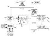
- FIG. 1shows a multiple-input, multiple-output (MIMO) receiver operating in accordance with exemplary embodiments of the present invention
- FIG. 2shows an exemplary 64-QAM encoding constellation as may be processed with the receiver of FIG. 1 ;
- FIG. 3shows an exemplary implementation for a MIMO demapper as might be employed for the MIMO detector of FIG. 1 ;
- FIG. 4shows an exemplary implementation for the mapper of FIG. 3 ;
- FIG. 5shows an exemplary candidate variable scan for the exemplary implementation of FIG. 4 ;
- FIG. 6shows an exemplary implementation for the difference term generator of FIG. 3 ;
- FIG. 7shows an exemplary implementation for the comparator of FIG. 3 .
- FIG. 1shows a multiple-input, multiple-output (MIMO) receiver 100 operating in accordance with exemplary embodiments of the present invention.
- Receiver 100comprises N r receive chains 190 ( 1 ) through 190 (Nr), where Nr is a positive.
- Nris a positive.
- a MIMO receivercomprises two or more receive chains, where each receive chain might operate in a similar manner.
- Receive chain 190 ( 1 )comprises antenna 101 , radio front end (RFE) 102 , channel selection filter (CSF) 103 , programmable gain amplifier (PGA) 104 , and sampler 105 .
- Antenna 101detects a signal from, for example, a wireless communication channel, where the signal might comprise two or more antenna signals generated by a MIMO transmitter.
- RFE 102receives the signal from antenna 101 , band filters and gain adjusts the antenna signal, and demodulates the antenna signal to base-band (BB) or near-BB.
- BBbase-band
- CSF 103filters the signal from RFE 102 so as to pass the desired information channel.
- CSF 103might be configured to operate for a WLAN according to the IEEE 802.11a/g standards for orthogonal frequency division multiplex (OFDM).
- OFDMorthogonal frequency division multiplex
- CSF 103has a bandwidth of approximately 20 MHz.
- PGA 104adjusts the signal from CSF 103 to be within the range supported by sampler 105 .
- Sampler 105periodically time-samples the signal from PGA 104 .
- Nr receive chains 109 ( 1 ) through 109 (Nr)are monitored by MIMO detector 106 to detect the data from the received signal.
- the signal from detectors 106is applied to processor 107 for subsequent processing and decoding. While processor 107 is shown in FIG. 1 as a single element, as would be apparent to one skilled in the art, the various processing of detected (e.g., encoded) data from MIMO detector 106 might be accomplished with two or more different processors.
- the exemplary embodiment of the present inventionis described herein with respect to a MIMO system employing quadrature amplitude modulation (QAM) encoding of data, though the present invention is not so limited.
- QAMquadrature amplitude modulation
- FIG. 2shows an exemplary 64-QAM encoding constellation.
- MIMO detector 106implements a MIMO demapping with soft-output maximum likelihood detection (SO MLD) in accordance with an exemplary embodiment of the present invention.
- SO MLDsoft-output maximum likelihood detection
- MIMO formulation of a log-likelihood approximation for SO MLDgenerates a soft-bit L(b k ) as follows in equation (1):
- the vector ris an N r -dimensional receive vector
- matrix His the (N r XN t )-dimensional MIMO channel matrix (characterizing the narrowband MIMO transmission wireless channel impulse response or transfer function), which might be estimated by the receiver through decoding of known preamble data.
- the receive vector rrepresents the signal received from the transmission medium that corresponds to the transmit vector x true passed through the channel with transfer function H and corrupted with additive noise n.
- Gray codingis employed that specifies that any two adjacent points only differ by one bit.
- each term y(x)is computed recursively using a doubly-recursive method with a candidate scanning order to reduce the overall number of computations.
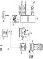
- FIG. 3shows an exemplary implementation for a MIMO demapper as might be employed for MIMO detector 106 of FIG. 1 .
- MIMO demapper 300comprises coefficient calculator (coeff-calc) 301 , difference term generator (DTG) 302 , counter 303 , mapper 304 , comparator unit 305 , accumulator 308 , and controller 309 .
- Controller 309might be employed to coordinate processing implemented by the various elements of FIG. 3 .
- Counter 303is employed to provide the clock cycle to DTG 302 and mapper 304 .
- Counter 303might be implemented as a 12-bit binary counter for 64-QAM.
- Coeff-calc 301computes various coefficients based on the input signals r and the MIMO channel matrix H, as described subsequently. These coefficients for i) r represent the received signal symbols (in-phase and quadrature phase) components for each receive antenna and ii) the estimated channel impulse response H measured and/or estimated separately by the receiver.
- DTG 302recursively pre-calculates a difference term based on the coefficients generated by coefficient calculator 301 , where the difference term corresponds to the metric difference d[i] between two consecutive candidates.
- DTG 302recursively pre-calculates the difference term based on the clock cycle i provided as the count value from counter 303 .
- DTG 302provides the difference term to accumulator 308 .
- each one of these candidate variables(A 1 , B 1 , A 2 , B 2 ): one real component and one imaginary component for each transmit antenna dimension.
- each one of these candidate variablestakes one of the signal alphabet values ⁇ 7, ⁇ 5, ⁇ 3, ⁇ 1, 1, 3, 5, 7 ⁇ .
- the metric yis updated according to this change.
- This variable changecorresponds to selecting one of the difference terms generated by DTG 302 , as described subsequently, and forwarding the selected difference term to accumulator 308 . With every change of one of the candidate variables, the difference variable itself is updated.
- Comparator unit 305determines the minimum y values for each of the two possible values (0,1) of each bit, by comparing the current y value for the current value of candidate variables under consideration with the previous minimum of y. At the end of the process, comparator unit 305 provides the differences between these two possible values (0,1) to subsequent processing (not shown in FIG. 3 ) as the desired SO MLD soft-bits (L(b k ) values).
- Mapper 304generates values to scan four candidate variables (A 1 , B 1 , A 2 , B 2 ) in a specific order based on the 12-bit binary counter from counter 303 .
- the sequence of counter valuese.g., 12-bit values
- Mapper 304Starting at its minimum value of ⁇ 7, each of the four candidate variables (A 1 , B 1 , A 2 , B 2 ) undergoes the triangular waveform scan by comparator 305 .
- each successive variableis scanned at a lower rate than the previous variable (e.g., A 1 is scanned faster than B 1 , B 1 is scanned faster than A 2 , and A 2 is scanned faster than B 2 ).
- the next high-level variableis updated before the next upward or downward slope is started.
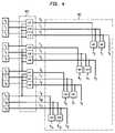
- FIG. 4shows an exemplary implementation for mapper 304 of FIG. 3 to generate bit values b 0 -b 11 for the candidate variables.
- Latches C 0 -C 11contain corresponding bit values for the count from counter 303 .
- Elements labeled “XOR”perform an exclusive logic OR on the identified input bits.
- the triangular waveform scanemploys segments of three bits, where each 3-bit segment corresponds to one of the candidate variables (A 1 , B 1 , A 2 , B 2 ). The 3-bit segment counts from 0 to 7 and then from 7 to 0 to point to the various elements of the signal alphabet ⁇ 7, ⁇ 5, ⁇ 3, ⁇ 1,1,3,5,7 ⁇ .
- the up-countis 000, 001, 010, 011, 100, 101, 110, 111, and for the down-count these values are inverted.
- Up/down counting by 3-bit segmentsis accomplished via XOR block 401 which XOR's each bit in a 3-bit block with a next higher level bit.
- bit values t 0 -t 11 of the up/down count of each 3-bit segmentmight not necessarily correspond to the bit values b 1 -b 11 of the encoded and modulated symbol.
- the corresponding binary representationis defined as [000, 100, 110, 010, 011, 111, 101, 001]. Consequently, XOR block 402 is employed to translate the bit values t 0 -t 11 of the up/down count into bit values b 1 -b 11 of the signal alphabet.
- FIG. 5shows an exemplary candidate variable scan for the exemplary implementation of FIG. 4 .
- each of the four candidate variables(A 1 , B 1 , A 2 , B 2 ) undergoes a “triangular waveform” shaped scan by counter 303 and mapper 304 , where variable B 1 is scanned 8 times more slowly than A 1 , A 2 is scanned 8 times more slowly than B 1 , and B 2 is scanned 8 times more slowly than A 2 .
- Coeff-calc 301 and DTG 302at any given clock cycle i, provide a difference term to accumulator 308 , as described previously, where the difference term corresponds to the metric difference d[i] between two consecutive candidates. Derivation of the coefficients and updating the difference term is now described. The vector-matrix notation of equation (4) is reduced and the result separated into various weights and coefficients.
- the weight coefficients w 1 through w 12are as given in equations (6), (7), (8), and (9):
- Coeff-calc 301generates values w1 through w12 based on the input vector r and channel impulse response matrix H. To simplify operation, coefficient calculator 301 then computes difference term coefficients e 0 through e 5 .
- DTG 302updates the difference da 1 , db 1 , da 2 , and db 2 using difference term coefficients e 0 through e 5 based on a logic implementation for the above pseudo-code.
- FIG. 6shows an exemplary logic implementation for DTG 302 of FIG. 3 .
- Latches 601 ( 1 ) through 601 ( 6 )store difference term coefficients e 0 through e 5 , respectively, from coeff-calc 301 (latched in through enable signals e_en[ 1 ] through e_en[ 5 ]).
- Mux 602provides one of difference term coefficients e 0 through e 5 in accordance with signal e_sel.
- the various signals of FIG. 6are generated by a controller (not shown in FIG. 6 ) implementing the tests of the above pseudo-code.
- the signal e_invis a control signal to invert the input difference term coefficient value of inverter 603
- d_invis a control signal to invert the difference term value of inverter 604
- e_zerois a control signal to mask the input difference term coefficient value in mask logic 605
- d_zerois a control signal to mask the difference term value in mask logic 606 .
- the signal d_selis a signal employed to select, as the output of mux 609 , one of the difference terms da 1 , db 1 , da 2 , and db 2 stored in latches 608 ( 1 ) through 608 ( 4 ), respectively (latched in through enable signals d_en[ 1 ] through d_en[ 3 ]).
- the select signal d_selis generated by a controller (not shown in FIG. 6 ) implementing the following tests:
- Combiner 607adds the values generated by mask logic 606 and 605 .
- FIG. 7shows an exemplary implementation 700 for comparator 305 of FIG. 3 that generates soft-bit values L 0 through L 11 in accordance with equation (1).
- a distance metricis generated for both the corresponding bit being a 1 or a 0, and the minimum value selected.
- the minimum searchis accomplished by storing the current minimum value and comparing the new candidate's Euclidean distance term to this stored minimum value.
- twelve soft-bit values L 0 through L 11are generated by corresponding minima blocks 710 ( 0 ) through 710 ( 11 ).
- minima block 710 ( k )comprises minimum calculator (min-calc) block 701 ( k ), flip-flops 702 ( k ) and 703 ( k ), multiplexer (mux) 704 ( k ), and combiner 705 ( k ).
- Min-calc block 701 ( k )compares the current value of y[i] with the previous minimum value from mux 704 ( k ), and selects the smaller value.
- the output of min-calc-block 701 ( k )is stored in flip-flops 702 ( k ) and 703 ( k ).
- Flip-flop 702 ( k )stores the minimum value if b k is a logic 1 and flip-flop 703 ( k ) stores the minimum value if b k is a logic 0.
- the soft-bit value L(b k )is calculated by combiner 705 ( k ) as the difference between the minimum value if b k is a logic 1 and the minimum value if b k is a logic 0.
- a multiple-branch wireless receiver operating in accordance with one or more embodiments of the present inventionmay provide one or more of the following advantages.
- MIMO mapping employing the SO MLD method described hereinreduces the complexity and power consumption of circuits generating candidate transmit vectors, while maintaining a relatively rapid computation and high probability of detection of the receiver.
- the present inventioncan be embodied in the form of methods and apparatuses for practicing those methods.
- the present inventioncan also be embodied in the form of program code embodied in tangible media, such as floppy diskettes, CD-ROMs, hard drives, or any other machine-readable storage medium, wherein, when the program code is loaded into and executed by a machine, such as a computer, the machine becomes an apparatus for practicing the invention.
- the present inventioncan also be embodied in the form of program code, for example, whether stored in a storage medium, loaded into and/or executed by a machine, or transmitted over some transmission medium, such as over electrical wiring or cabling, through fiber optics, or via electromagnetic radiation, wherein, when the program code is loaded into and executed by a machine, such as a computer, the machine becomes an apparatus for practicing the invention.
- program codeWhen implemented on a general-purpose processor, the program code segments combine with the processor to provide a unique device that operates analogously to specific logic circuits.
Landscapes
- Engineering & Computer Science (AREA)
- Power Engineering (AREA)
- Computer Networks & Wireless Communication (AREA)
- Signal Processing (AREA)
- Radio Transmission System (AREA)
Abstract
Description
where L(bk) is the soft-bit for the kth bit, k=0,1, . . . , K−1, coded into the MIMO-QAM symbol. For Nt=2 and 64-QAM encoding, K=12, since (2 subcarriers)(6 bits per symbol)=12 bits are decoded per MIMO-OFDM subcarrier. The vector r is an Nr-dimensional receive vector, and matrix H is the (NrXNt)-dimensional MIMO channel matrix (characterizing the narrowband MIMO transmission wireless channel impulse response or transfer function), which might be estimated by the receiver through decoding of known preamble data. The transmit vector x is the Nt-dimensional candidate transmit vector which is a direction function ƒ(•) (e.g., QAM mapping) of the set of all bits b={bk} modulated into it, as defined by equation (2):
x=ƒ(b)=x(b) (2)
The receive vector r represents the signal received from the transmission medium that corresponds to the transmit vector xtruepassed through the channel with transfer function H and corrupted with additive noise n. Thus, the receive vector r is as defined in equation (3):
r=Hxtrue+n (3)
where each complex element in the vector xtruecorresponds to one constellation point of
y(x)=y(x(b))=∥r−Hx(b)∥2. (4)
is minimum.
da1=ΔyA1=2w1−24w5−14w9−14w10 (5a)
db1=ΔyB1=2w2−24w6−14w11−14w12 (5b)
da2=ΔyA2=2w3−24w7−14w9+14w11 (5c)
db2=ΔyB2=2w4−24w8−14w10−14w12 (5d)
The weight coefficients w1through w12are as given in equations (6), (7), (8), and (9):
where h(.)are channel impulse response coefficients, r(.)are receive signal coefficients, and subscripts I and Q represent the in-phase and quadrature-phase component values, respectively.
where the function “mod(b,m)” means b modulo m.
e0=8w6=8w5 (10)
e1=4w10=−4w11 (11)
e2=4w12=4w9 (12)
e3=8w8 (13)
e4=8w7+28w11 (14)
e5=8w7−28w11 (15)
Claims (27)
Priority Applications (2)
| Application Number | Priority Date | Filing Date | Title |
|---|---|---|---|
| US10/990,910US7583762B2 (en) | 2004-11-17 | 2004-11-17 | Reduced-complexity multiple-input, multiple-output detection |
| US12/508,697US8077812B2 (en) | 2004-11-17 | 2009-07-24 | Reduced-complexity multiple-input, multiple-output detection |
Applications Claiming Priority (1)
| Application Number | Priority Date | Filing Date | Title |
|---|---|---|---|
| US10/990,910US7583762B2 (en) | 2004-11-17 | 2004-11-17 | Reduced-complexity multiple-input, multiple-output detection |
Related Child Applications (1)
| Application Number | Title | Priority Date | Filing Date |
|---|---|---|---|
| US12/508,697ContinuationUS8077812B2 (en) | 2004-11-17 | 2009-07-24 | Reduced-complexity multiple-input, multiple-output detection |
Publications (2)
| Publication Number | Publication Date |
|---|---|
| US20060104390A1 US20060104390A1 (en) | 2006-05-18 |
| US7583762B2true US7583762B2 (en) | 2009-09-01 |
Family
ID=36386257
Family Applications (2)
| Application Number | Title | Priority Date | Filing Date |
|---|---|---|---|
| US10/990,910Expired - Fee RelatedUS7583762B2 (en) | 2004-11-17 | 2004-11-17 | Reduced-complexity multiple-input, multiple-output detection |
| US12/508,697Expired - Fee RelatedUS8077812B2 (en) | 2004-11-17 | 2009-07-24 | Reduced-complexity multiple-input, multiple-output detection |
Family Applications After (1)
| Application Number | Title | Priority Date | Filing Date |
|---|---|---|---|
| US12/508,697Expired - Fee RelatedUS8077812B2 (en) | 2004-11-17 | 2009-07-24 | Reduced-complexity multiple-input, multiple-output detection |
Country Status (1)
| Country | Link |
|---|---|
| US (2) | US7583762B2 (en) |
Cited By (2)
| Publication number | Priority date | Publication date | Assignee | Title |
|---|---|---|---|---|
| US20110222618A1 (en)* | 2010-03-11 | 2011-09-15 | Fredrik Huss | Method and Apparatus for Efficient Soft Modulation for Gray-Mapped QAM Symbols |
| CN108736935A (en)* | 2018-05-18 | 2018-11-02 | 东南大学 | A kind of general down and out options method for extensive mimo system signal detection |
Families Citing this family (90)
| Publication number | Priority date | Publication date | Assignee | Title |
|---|---|---|---|---|
| US20070019756A1 (en)* | 2005-07-25 | 2007-01-25 | Navini Networks, Inc. | Low complexity soft detection in multiple transmit and receive antenna systems with M-QAM modulations |
| US20070070877A1 (en)* | 2005-09-27 | 2007-03-29 | Thomas Sun | Modulation type determination for evaluation of transmitter performance |
| US7542743B2 (en)* | 2005-09-30 | 2009-06-02 | Broadcom Corporation | Maximum likelihood detection for MIMO receivers |
| KR100866805B1 (en)* | 2006-04-06 | 2008-11-04 | 삼성전자주식회사 | Apparatus and method for generating log likelihood ratio in multi-antenna communication system |
| KR100922961B1 (en) | 2006-10-12 | 2009-10-22 | 삼성전자주식회사 | Signal detecting apparatus and method in a communication system using multiple antennas |
| US20090074114A1 (en)* | 2007-09-13 | 2009-03-19 | Eric Ojard | Method and System for Approximate Maximum Likelihood (ML) Detection in a Multiple Input Multiple Output (MIMO) Receiver |
| US8234320B1 (en)* | 2007-10-25 | 2012-07-31 | Marvell International Ltd. | Bitwise comparator for selecting two smallest numbers from a set of numbers |
| US20110026575A1 (en)* | 2008-04-02 | 2011-02-03 | Obimey Ltd. | Method and Apparatus For Enhanced Performance and Crosstalk Measurement in a MIMO Communication System |
| US9999038B2 (en) | 2013-05-31 | 2018-06-12 | At&T Intellectual Property I, L.P. | Remote distributed antenna system |
| US10063280B2 (en) | 2014-09-17 | 2018-08-28 | At&T Intellectual Property I, L.P. | Monitoring and mitigating conditions in a communication network |
| US9615269B2 (en) | 2014-10-02 | 2017-04-04 | At&T Intellectual Property I, L.P. | Method and apparatus that provides fault tolerance in a communication network |
| US9503189B2 (en) | 2014-10-10 | 2016-11-22 | At&T Intellectual Property I, L.P. | Method and apparatus for arranging communication sessions in a communication system |
| US9973299B2 (en) | 2014-10-14 | 2018-05-15 | At&T Intellectual Property I, L.P. | Method and apparatus for adjusting a mode of communication in a communication network |
| US9312919B1 (en) | 2014-10-21 | 2016-04-12 | At&T Intellectual Property I, Lp | Transmission device with impairment compensation and methods for use therewith |
| US9769020B2 (en) | 2014-10-21 | 2017-09-19 | At&T Intellectual Property I, L.P. | Method and apparatus for responding to events affecting communications in a communication network |
| US9544006B2 (en) | 2014-11-20 | 2017-01-10 | At&T Intellectual Property I, L.P. | Transmission device with mode division multiplexing and methods for use therewith |
| US10009067B2 (en) | 2014-12-04 | 2018-06-26 | At&T Intellectual Property I, L.P. | Method and apparatus for configuring a communication interface |
| US9461706B1 (en) | 2015-07-31 | 2016-10-04 | At&T Intellectual Property I, Lp | Method and apparatus for exchanging communication signals |
| US10243784B2 (en) | 2014-11-20 | 2019-03-26 | At&T Intellectual Property I, L.P. | System for generating topology information and methods thereof |
| US9997819B2 (en) | 2015-06-09 | 2018-06-12 | At&T Intellectual Property I, L.P. | Transmission medium and method for facilitating propagation of electromagnetic waves via a core |
| US9800327B2 (en) | 2014-11-20 | 2017-10-24 | At&T Intellectual Property I, L.P. | Apparatus for controlling operations of a communication device and methods thereof |
| US9954287B2 (en) | 2014-11-20 | 2018-04-24 | At&T Intellectual Property I, L.P. | Apparatus for converting wireless signals and electromagnetic waves and methods thereof |
| US9876570B2 (en) | 2015-02-20 | 2018-01-23 | At&T Intellectual Property I, Lp | Guided-wave transmission device with non-fundamental mode propagation and methods for use therewith |
| US9705561B2 (en) | 2015-04-24 | 2017-07-11 | At&T Intellectual Property I, L.P. | Directional coupling device and methods for use therewith |
| US10224981B2 (en) | 2015-04-24 | 2019-03-05 | At&T Intellectual Property I, Lp | Passive electrical coupling device and methods for use therewith |
| US9793954B2 (en) | 2015-04-28 | 2017-10-17 | At&T Intellectual Property I, L.P. | Magnetic coupling device and methods for use therewith |
| US9871282B2 (en) | 2015-05-14 | 2018-01-16 | At&T Intellectual Property I, L.P. | At least one transmission medium having a dielectric surface that is covered at least in part by a second dielectric |
| US9490869B1 (en) | 2015-05-14 | 2016-11-08 | At&T Intellectual Property I, L.P. | Transmission medium having multiple cores and methods for use therewith |
| US10650940B2 (en) | 2015-05-15 | 2020-05-12 | At&T Intellectual Property I, L.P. | Transmission medium having a conductive material and methods for use therewith |
| US9917341B2 (en) | 2015-05-27 | 2018-03-13 | At&T Intellectual Property I, L.P. | Apparatus and method for launching electromagnetic waves and for modifying radial dimensions of the propagating electromagnetic waves |
| US10812174B2 (en) | 2015-06-03 | 2020-10-20 | At&T Intellectual Property I, L.P. | Client node device and methods for use therewith |
| US9866309B2 (en) | 2015-06-03 | 2018-01-09 | At&T Intellectual Property I, Lp | Host node device and methods for use therewith |
| US10103801B2 (en) | 2015-06-03 | 2018-10-16 | At&T Intellectual Property I, L.P. | Host node device and methods for use therewith |
| US9912381B2 (en) | 2015-06-03 | 2018-03-06 | At&T Intellectual Property I, Lp | Network termination and methods for use therewith |
| US9913139B2 (en) | 2015-06-09 | 2018-03-06 | At&T Intellectual Property I, L.P. | Signal fingerprinting for authentication of communicating devices |
| US9820146B2 (en) | 2015-06-12 | 2017-11-14 | At&T Intellectual Property I, L.P. | Method and apparatus for authentication and identity management of communicating devices |
| US9362990B1 (en)* | 2015-06-16 | 2016-06-07 | Mbit Wireless, Inc. | Method and apparatus for precomputation based MIMO decoder |
| US9865911B2 (en) | 2015-06-25 | 2018-01-09 | At&T Intellectual Property I, L.P. | Waveguide system for slot radiating first electromagnetic waves that are combined into a non-fundamental wave mode second electromagnetic wave on a transmission medium |
| US9640850B2 (en) | 2015-06-25 | 2017-05-02 | At&T Intellectual Property I, L.P. | Methods and apparatus for inducing a non-fundamental wave mode on a transmission medium |
| US9509415B1 (en) | 2015-06-25 | 2016-11-29 | At&T Intellectual Property I, L.P. | Methods and apparatus for inducing a fundamental wave mode on a transmission medium |
| US10044409B2 (en) | 2015-07-14 | 2018-08-07 | At&T Intellectual Property I, L.P. | Transmission medium and methods for use therewith |
| US9853342B2 (en) | 2015-07-14 | 2017-12-26 | At&T Intellectual Property I, L.P. | Dielectric transmission medium connector and methods for use therewith |
| US10205655B2 (en) | 2015-07-14 | 2019-02-12 | At&T Intellectual Property I, L.P. | Apparatus and methods for communicating utilizing an antenna array and multiple communication paths |
| US10148016B2 (en) | 2015-07-14 | 2018-12-04 | At&T Intellectual Property I, L.P. | Apparatus and methods for communicating utilizing an antenna array |
| US9882257B2 (en) | 2015-07-14 | 2018-01-30 | At&T Intellectual Property I, L.P. | Method and apparatus for launching a wave mode that mitigates interference |
| US9628116B2 (en) | 2015-07-14 | 2017-04-18 | At&T Intellectual Property I, L.P. | Apparatus and methods for transmitting wireless signals |
| US9847566B2 (en) | 2015-07-14 | 2017-12-19 | At&T Intellectual Property I, L.P. | Method and apparatus for adjusting a field of a signal to mitigate interference |
| US10090606B2 (en) | 2015-07-15 | 2018-10-02 | At&T Intellectual Property I, L.P. | Antenna system with dielectric array and methods for use therewith |
| US9749053B2 (en) | 2015-07-23 | 2017-08-29 | At&T Intellectual Property I, L.P. | Node device, repeater and methods for use therewith |
| US9871283B2 (en) | 2015-07-23 | 2018-01-16 | At&T Intellectual Property I, Lp | Transmission medium having a dielectric core comprised of plural members connected by a ball and socket configuration |
| US9948333B2 (en) | 2015-07-23 | 2018-04-17 | At&T Intellectual Property I, L.P. | Method and apparatus for wireless communications to mitigate interference |
| US9912027B2 (en) | 2015-07-23 | 2018-03-06 | At&T Intellectual Property I, L.P. | Method and apparatus for exchanging communication signals |
| US9735833B2 (en) | 2015-07-31 | 2017-08-15 | At&T Intellectual Property I, L.P. | Method and apparatus for communications management in a neighborhood network |
| US9967173B2 (en) | 2015-07-31 | 2018-05-08 | At&T Intellectual Property I, L.P. | Method and apparatus for authentication and identity management of communicating devices |
| US9904535B2 (en) | 2015-09-14 | 2018-02-27 | At&T Intellectual Property I, L.P. | Method and apparatus for distributing software |
| US9769128B2 (en) | 2015-09-28 | 2017-09-19 | At&T Intellectual Property I, L.P. | Method and apparatus for encryption of communications over a network |
| US9876264B2 (en) | 2015-10-02 | 2018-01-23 | At&T Intellectual Property I, Lp | Communication system, guided wave switch and methods for use therewith |
| US10355367B2 (en) | 2015-10-16 | 2019-07-16 | At&T Intellectual Property I, L.P. | Antenna structure for exchanging wireless signals |
| US9860075B1 (en) | 2016-08-26 | 2018-01-02 | At&T Intellectual Property I, L.P. | Method and communication node for broadband distribution |
| US10811767B2 (en) | 2016-10-21 | 2020-10-20 | At&T Intellectual Property I, L.P. | System and dielectric antenna with convex dielectric radome |
| US10312567B2 (en) | 2016-10-26 | 2019-06-04 | At&T Intellectual Property I, L.P. | Launcher with planar strip antenna and methods for use therewith |
| US10225025B2 (en) | 2016-11-03 | 2019-03-05 | At&T Intellectual Property I, L.P. | Method and apparatus for detecting a fault in a communication system |
| US10178445B2 (en) | 2016-11-23 | 2019-01-08 | At&T Intellectual Property I, L.P. | Methods, devices, and systems for load balancing between a plurality of waveguides |
| US10727599B2 (en) | 2016-12-06 | 2020-07-28 | At&T Intellectual Property I, L.P. | Launcher with slot antenna and methods for use therewith |
| US10819035B2 (en) | 2016-12-06 | 2020-10-27 | At&T Intellectual Property I, L.P. | Launcher with helical antenna and methods for use therewith |
| US10694379B2 (en) | 2016-12-06 | 2020-06-23 | At&T Intellectual Property I, L.P. | Waveguide system with device-based authentication and methods for use therewith |
| US10637149B2 (en) | 2016-12-06 | 2020-04-28 | At&T Intellectual Property I, L.P. | Injection molded dielectric antenna and methods for use therewith |
| US10139820B2 (en) | 2016-12-07 | 2018-11-27 | At&T Intellectual Property I, L.P. | Method and apparatus for deploying equipment of a communication system |
| US10547348B2 (en) | 2016-12-07 | 2020-01-28 | At&T Intellectual Property I, L.P. | Method and apparatus for switching transmission mediums in a communication system |
| US10359749B2 (en) | 2016-12-07 | 2019-07-23 | At&T Intellectual Property I, L.P. | Method and apparatus for utilities management via guided wave communication |
| US10446936B2 (en) | 2016-12-07 | 2019-10-15 | At&T Intellectual Property I, L.P. | Multi-feed dielectric antenna system and methods for use therewith |
| US10168695B2 (en) | 2016-12-07 | 2019-01-01 | At&T Intellectual Property I, L.P. | Method and apparatus for controlling an unmanned aircraft |
| US10243270B2 (en) | 2016-12-07 | 2019-03-26 | At&T Intellectual Property I, L.P. | Beam adaptive multi-feed dielectric antenna system and methods for use therewith |
| US10389029B2 (en) | 2016-12-07 | 2019-08-20 | At&T Intellectual Property I, L.P. | Multi-feed dielectric antenna system with core selection and methods for use therewith |
| US9893795B1 (en) | 2016-12-07 | 2018-02-13 | At&T Intellectual Property I, Lp | Method and repeater for broadband distribution |
| US10326689B2 (en) | 2016-12-08 | 2019-06-18 | At&T Intellectual Property I, L.P. | Method and system for providing alternative communication paths |
| US10777873B2 (en) | 2016-12-08 | 2020-09-15 | At&T Intellectual Property I, L.P. | Method and apparatus for mounting network devices |
| US9998870B1 (en) | 2016-12-08 | 2018-06-12 | At&T Intellectual Property I, L.P. | Method and apparatus for proximity sensing |
| US10069535B2 (en) | 2016-12-08 | 2018-09-04 | At&T Intellectual Property I, L.P. | Apparatus and methods for launching electromagnetic waves having a certain electric field structure |
| US10530505B2 (en) | 2016-12-08 | 2020-01-07 | At&T Intellectual Property I, L.P. | Apparatus and methods for launching electromagnetic waves along a transmission medium |
| US10601494B2 (en) | 2016-12-08 | 2020-03-24 | At&T Intellectual Property I, L.P. | Dual-band communication device and method for use therewith |
| US10938108B2 (en) | 2016-12-08 | 2021-03-02 | At&T Intellectual Property I, L.P. | Frequency selective multi-feed dielectric antenna system and methods for use therewith |
| US10389037B2 (en) | 2016-12-08 | 2019-08-20 | At&T Intellectual Property I, L.P. | Apparatus and methods for selecting sections of an antenna array and use therewith |
| US9911020B1 (en) | 2016-12-08 | 2018-03-06 | At&T Intellectual Property I, L.P. | Method and apparatus for tracking via a radio frequency identification device |
| US10103422B2 (en) | 2016-12-08 | 2018-10-16 | At&T Intellectual Property I, L.P. | Method and apparatus for mounting network devices |
| US9838896B1 (en) | 2016-12-09 | 2017-12-05 | At&T Intellectual Property I, L.P. | Method and apparatus for assessing network coverage |
| US10340983B2 (en) | 2016-12-09 | 2019-07-02 | At&T Intellectual Property I, L.P. | Method and apparatus for surveying remote sites via guided wave communications |
| US10264586B2 (en) | 2016-12-09 | 2019-04-16 | At&T Mobility Ii Llc | Cloud-based packet controller and methods for use therewith |
| US9973940B1 (en) | 2017-02-27 | 2018-05-15 | At&T Intellectual Property I, L.P. | Apparatus and methods for dynamic impedance matching of a guided wave launcher |
| US10298293B2 (en) | 2017-03-13 | 2019-05-21 | At&T Intellectual Property I, L.P. | Apparatus of communication utilizing wireless network devices |
Citations (8)
| Publication number | Priority date | Publication date | Assignee | Title |
|---|---|---|---|---|
| US5418795A (en)* | 1991-09-13 | 1995-05-23 | Sony Corporation | Viterbi decoder with path metric comparisons for increased decoding rate and with normalization timing calculation |
| US5636251A (en) | 1994-07-08 | 1997-06-03 | Zenith Electronics Corporation | Receiver for a trellis coded digital television signal |
| US6404828B2 (en) | 1997-03-12 | 2002-06-11 | Interdigital Technology Corporation | Multichannel decoder |
| US20040071235A1 (en)* | 2002-08-21 | 2004-04-15 | Love David J. | Low complexity high performance decoder and method of decoding for communications systems using multidimensional signaling |
| US7065147B2 (en) | 2000-07-12 | 2006-06-20 | Texas Instruments Incorporated | System and method of data communication using turbo trellis coded modulation combined with constellation shaping with or without precoding |
| US20060150058A1 (en) | 2004-12-30 | 2006-07-06 | Freescale Semiconductor, Inc. | Track buffer in a parallel decoder |
| US7161994B2 (en) | 2001-09-17 | 2007-01-09 | Digeo, Inc. | System and method for shared decoding |
| US7321644B2 (en)* | 2004-06-08 | 2008-01-22 | Texas Instruments Incorporated | Low-complexity, symbol-based, reduced substreams maximum likelihood decoder and method for a multiple-input, multiple-output communication system |
Family Cites Families (2)
| Publication number | Priority date | Publication date | Assignee | Title |
|---|---|---|---|---|
| US7433432B2 (en)* | 2004-12-31 | 2008-10-07 | Broadcom Corporation | Adaptive detector for multiple-data-path systems |
| US7978793B2 (en)* | 2008-02-06 | 2011-07-12 | Freescale Semiconductor, Inc. | Method for generating soft decision signal from hard decision signal in a receiver system |
- 2004
- 2004-11-17USUS10/990,910patent/US7583762B2/ennot_activeExpired - Fee Related
- 2009
- 2009-07-24USUS12/508,697patent/US8077812B2/ennot_activeExpired - Fee Related
Patent Citations (8)
| Publication number | Priority date | Publication date | Assignee | Title |
|---|---|---|---|---|
| US5418795A (en)* | 1991-09-13 | 1995-05-23 | Sony Corporation | Viterbi decoder with path metric comparisons for increased decoding rate and with normalization timing calculation |
| US5636251A (en) | 1994-07-08 | 1997-06-03 | Zenith Electronics Corporation | Receiver for a trellis coded digital television signal |
| US6404828B2 (en) | 1997-03-12 | 2002-06-11 | Interdigital Technology Corporation | Multichannel decoder |
| US7065147B2 (en) | 2000-07-12 | 2006-06-20 | Texas Instruments Incorporated | System and method of data communication using turbo trellis coded modulation combined with constellation shaping with or without precoding |
| US7161994B2 (en) | 2001-09-17 | 2007-01-09 | Digeo, Inc. | System and method for shared decoding |
| US20040071235A1 (en)* | 2002-08-21 | 2004-04-15 | Love David J. | Low complexity high performance decoder and method of decoding for communications systems using multidimensional signaling |
| US7321644B2 (en)* | 2004-06-08 | 2008-01-22 | Texas Instruments Incorporated | Low-complexity, symbol-based, reduced substreams maximum likelihood decoder and method for a multiple-input, multiple-output communication system |
| US20060150058A1 (en) | 2004-12-30 | 2006-07-06 | Freescale Semiconductor, Inc. | Track buffer in a parallel decoder |
Non-Patent Citations (1)
| Title |
|---|
| Filippo et al."Simplified Soft-Output Demapper for Binary Interleaved COFDM with Application to HIPERLAN/2" Proc. IEEE Int. Conf. Commun. (ICC) Apr. 2002.* |
Cited By (4)
| Publication number | Priority date | Publication date | Assignee | Title |
|---|---|---|---|---|
| US20110222618A1 (en)* | 2010-03-11 | 2011-09-15 | Fredrik Huss | Method and Apparatus for Efficient Soft Modulation for Gray-Mapped QAM Symbols |
| US8340202B2 (en) | 2010-03-11 | 2012-12-25 | Telefonaktiebolaget Lm Ericsson (Publ) | Method and apparatus for efficient soft modulation for gray-mapped QAM symbols |
| CN108736935A (en)* | 2018-05-18 | 2018-11-02 | 东南大学 | A kind of general down and out options method for extensive mimo system signal detection |
| CN108736935B (en)* | 2018-05-18 | 2021-02-26 | 东南大学 | A Universal Descent Search Method for Signal Detection in Massive MIMO Systems |
Also Published As
| Publication number | Publication date |
|---|---|
| US20090304124A1 (en) | 2009-12-10 |
| US20060104390A1 (en) | 2006-05-18 |
| US8077812B2 (en) | 2011-12-13 |
Similar Documents
| Publication | Publication Date | Title |
|---|---|---|
| US7583762B2 (en) | Reduced-complexity multiple-input, multiple-output detection | |
| US8462867B2 (en) | Near soft-output maximum-likelihood detection for multiple-input multiple-output systems | |
| US8351529B2 (en) | Apparatus and method for detecting communications from multiple sources | |
| US7095812B2 (en) | Reduced complexity receiver for space-time- bit-interleaved coded modulation | |
| US9231794B2 (en) | Method and apparatus for multiple antenna communications, computer program product therefor | |
| US20060215781A1 (en) | Method for detecting and decoding a signal in a MIMO communication system | |
| US8155248B2 (en) | Equalizing structure and equalizing method | |
| US20100061438A1 (en) | Method for selecting transmission parameters for a data transmission and data transmission controller | |
| EP1416688A1 (en) | Iterative channel estimation in multicarrier receivers | |
| US7649966B2 (en) | System for soft symbol decoding with MIMO log-map detection | |
| US9654252B2 (en) | Low complexity maximum-likelihood-based method for estimating emitted symbols in a SM-MIMO receiver | |
| US8194798B2 (en) | MIMO symbol decoder and method for decoding spatially multiplexed symbols using combined linear equalization and maximum likelihood decoding | |
| US9048975B2 (en) | Method and apparatus for soft-decision detection in 2×2 MIMO system | |
| EP1895727B1 (en) | Equalizing structure based on a List MLD detection scheme and a corresponding method | |
| US7729458B2 (en) | Signal decoding apparatus, signal decoding method, program, and information record medium | |
| US8254507B2 (en) | Method and system for SFBC/STBC in a communication diversity system using angle feedback | |
| JP5001314B2 (en) | Radio base station apparatus and modulation / coding method selection method | |
| US9160578B2 (en) | Turbo equalisation | |
| US9628152B2 (en) | Signal detection method and apparatus in MIMO communication system | |
| US20120142399A1 (en) | Radio base station apparatus and modulation/coding scheme selecting method | |
| US7676001B2 (en) | MLD demapping using sub-metrics for soft-output MIMO detection and the like | |
| US7876847B2 (en) | Global minimum-based MLD demapping for soft-output MIMO detection | |
| Ketseoglou et al. | Optimized iterative (Turbo) reception for QAM OFDM with CFO over unknown double-selective channels | |
| Ebihara et al. | Joint MCS selection for MLD based signal detection in 4× 4 OFDM-MIMO multiplexing with multi-codeword transmission | |
| Peng et al. | Near Optimal Combining Scheme for MIMO-OFDM HARQ with Bit Rearrangement |
Legal Events
| Date | Code | Title | Description |
|---|---|---|---|
| AS | Assignment | Owner name:AGERE SYSTEMS INC., PENNSYLVANIA Free format text:ASSIGNMENT OF ASSIGNORS INTEREST;ASSIGNORS:GRAEF, NILS;HAMMERSCHMIDT, JOACHIM S.;REEL/FRAME:016003/0694;SIGNING DATES FROM 20041115 TO 20041116 | |
| FPAY | Fee payment | Year of fee payment:4 | |
| AS | Assignment | Owner name:DEUTSCHE BANK AG NEW YORK BRANCH, AS COLLATERAL AG Free format text:PATENT SECURITY AGREEMENT;ASSIGNORS:LSI CORPORATION;AGERE SYSTEMS LLC;REEL/FRAME:032856/0031 Effective date:20140506 | |
| AS | Assignment | Owner name:AVAGO TECHNOLOGIES GENERAL IP (SINGAPORE) PTE. LTD Free format text:ASSIGNMENT OF ASSIGNORS INTEREST;ASSIGNOR:AGERE SYSTEMS LLC;REEL/FRAME:035365/0634 Effective date:20140804 | |
| AS | Assignment | Owner name:AGERE SYSTEMS LLC, PENNSYLVANIA Free format text:TERMINATION AND RELEASE OF SECURITY INTEREST IN PATENT RIGHTS (RELEASES RF 032856-0031);ASSIGNOR:DEUTSCHE BANK AG NEW YORK BRANCH, AS COLLATERAL AGENT;REEL/FRAME:037684/0039 Effective date:20160201 Owner name:LSI CORPORATION, CALIFORNIA Free format text:TERMINATION AND RELEASE OF SECURITY INTEREST IN PATENT RIGHTS (RELEASES RF 032856-0031);ASSIGNOR:DEUTSCHE BANK AG NEW YORK BRANCH, AS COLLATERAL AGENT;REEL/FRAME:037684/0039 Effective date:20160201 | |
| AS | Assignment | Owner name:BANK OF AMERICA, N.A., AS COLLATERAL AGENT, NORTH CAROLINA Free format text:PATENT SECURITY AGREEMENT;ASSIGNOR:AVAGO TECHNOLOGIES GENERAL IP (SINGAPORE) PTE. LTD.;REEL/FRAME:037808/0001 Effective date:20160201 Owner name:BANK OF AMERICA, N.A., AS COLLATERAL AGENT, NORTH Free format text:PATENT SECURITY AGREEMENT;ASSIGNOR:AVAGO TECHNOLOGIES GENERAL IP (SINGAPORE) PTE. LTD.;REEL/FRAME:037808/0001 Effective date:20160201 | |
| AS | Assignment | Owner name:AVAGO TECHNOLOGIES GENERAL IP (SINGAPORE) PTE. LTD., SINGAPORE Free format text:TERMINATION AND RELEASE OF SECURITY INTEREST IN PATENTS;ASSIGNOR:BANK OF AMERICA, N.A., AS COLLATERAL AGENT;REEL/FRAME:041710/0001 Effective date:20170119 Owner name:AVAGO TECHNOLOGIES GENERAL IP (SINGAPORE) PTE. LTD Free format text:TERMINATION AND RELEASE OF SECURITY INTEREST IN PATENTS;ASSIGNOR:BANK OF AMERICA, N.A., AS COLLATERAL AGENT;REEL/FRAME:041710/0001 Effective date:20170119 | |
| REMI | Maintenance fee reminder mailed | ||
| LAPS | Lapse for failure to pay maintenance fees | Free format text:PATENT EXPIRED FOR FAILURE TO PAY MAINTENANCE FEES (ORIGINAL EVENT CODE: EXP.) | |
| STCH | Information on status: patent discontinuation | Free format text:PATENT EXPIRED DUE TO NONPAYMENT OF MAINTENANCE FEES UNDER 37 CFR 1.362 | |
| FP | Expired due to failure to pay maintenance fee | Effective date:20170901 |