US7583660B2 - Method and apparatus for enabling peer-to-peer communication between endpoints on a per call basis - Google Patents
Method and apparatus for enabling peer-to-peer communication between endpoints on a per call basisDownload PDFInfo
- Publication number
- US7583660B2 US7583660B2US11/108,937US10893705AUS7583660B2US 7583660 B2US7583660 B2US 7583660B2US 10893705 AUS10893705 AUS 10893705AUS 7583660 B2US7583660 B2US 7583660B2
- Authority
- US
- United States
- Prior art keywords
- peer
- endpoint device
- network
- call
- communication network
- Prior art date
- Legal status (The legal status is an assumption and is not a legal conclusion. Google has not performed a legal analysis and makes no representation as to the accuracy of the status listed.)
- Active, expires
Links
Images


Classifications
- H—ELECTRICITY
- H04—ELECTRIC COMMUNICATION TECHNIQUE
- H04L—TRANSMISSION OF DIGITAL INFORMATION, e.g. TELEGRAPHIC COMMUNICATION
- H04L65/00—Network arrangements, protocols or services for supporting real-time applications in data packet communication
- H04L65/1066—Session management
- H04L65/1069—Session establishment or de-establishment
- H—ELECTRICITY
- H04—ELECTRIC COMMUNICATION TECHNIQUE
- H04L—TRANSMISSION OF DIGITAL INFORMATION, e.g. TELEGRAPHIC COMMUNICATION
- H04L65/00—Network arrangements, protocols or services for supporting real-time applications in data packet communication
- H04L65/10—Architectures or entities
- H04L65/102—Gateways
- H04L65/1023—Media gateways
- H04L65/103—Media gateways in the network
- H—ELECTRICITY
- H04—ELECTRIC COMMUNICATION TECHNIQUE
- H04L—TRANSMISSION OF DIGITAL INFORMATION, e.g. TELEGRAPHIC COMMUNICATION
- H04L65/00—Network arrangements, protocols or services for supporting real-time applications in data packet communication
- H04L65/10—Architectures or entities
- H04L65/102—Gateways
- H04L65/1033—Signalling gateways
- H04L65/104—Signalling gateways in the network
- H—ELECTRICITY
- H04—ELECTRIC COMMUNICATION TECHNIQUE
- H04L—TRANSMISSION OF DIGITAL INFORMATION, e.g. TELEGRAPHIC COMMUNICATION
- H04L65/00—Network arrangements, protocols or services for supporting real-time applications in data packet communication
- H04L65/10—Architectures or entities
- H04L65/102—Gateways
- H04L65/1043—Gateway controllers, e.g. media gateway control protocol [MGCP] controllers
- H—ELECTRICITY
- H04—ELECTRIC COMMUNICATION TECHNIQUE
- H04L—TRANSMISSION OF DIGITAL INFORMATION, e.g. TELEGRAPHIC COMMUNICATION
- H04L65/00—Network arrangements, protocols or services for supporting real-time applications in data packet communication
- H04L65/1066—Session management
- H04L65/1101—Session protocols
- H04L65/1104—Session initiation protocol [SIP]
- H—ELECTRICITY
- H04—ELECTRIC COMMUNICATION TECHNIQUE
- H04M—TELEPHONIC COMMUNICATION
- H04M7/00—Arrangements for interconnection between switching centres
- H04M7/006—Networks other than PSTN/ISDN providing telephone service, e.g. Voice over Internet Protocol (VoIP), including next generation networks with a packet-switched transport layer
- H04M7/0063—Networks other than PSTN/ISDN providing telephone service, e.g. Voice over Internet Protocol (VoIP), including next generation networks with a packet-switched transport layer where the network is a peer-to-peer network
Definitions
- the present inventionrelates generally to communication networks and, more particularly, to a method and apparatus for enabling peer-to-peer communication between endpoints on a per call basis in packet networks, e.g. Voice over Internet Protocol (VoIP) networks.
- VoIPVoice over Internet Protocol
- Network service providersoffer many network features that provide enhanced services for both the signaling and the media path for calls between two endpoints. Redirection and transcoding services are examples of these enhanced network services. Occasionally, for a variety of reasons, users may want to avoid using the network to process signaling and media messages in order to keep their communication channels completely private and transparent to the network.
- network endpointse.g., VoIP network endpoints
- a packet networke.g., a VoIP network.
- the present inventionenables a user to signal to the network that a call to be initiated or a call that is in progress needs to occur in a peer-to-peer relationship with the terminating endpoint.
- the networkwill then remove itself from the call signaling and media path and direct the signaling and media communication to occur directly between the two endpoints.
- FIG. 1illustrates an exemplary Voice over Internet Protocol (VoIP) network related to the present invention
- FIG. 2illustrates an example of enabling peer-to-peer communication between VoIP endpoints on a per call basis in a VoIP network of the present invention
- FIG. 3illustrates a flowchart of a method for signaling the network to enable peer-to-peer communication in a VoIP network of the present invention
- FIG. 4illustrates a flowchart of a method for disabling the VoIP network from processing signaling and media communication in a VoIP network of the present invention
- FIG. 5illustrates a high level block diagram of a general purpose computer suitable for use in performing the functions described herein.
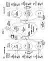
- FIG. 1illustrates an example network, e.g., a packet network such as a VoIP network related to the present invention.
- exemplary packet networksinclude internet protocol (IP) networks, asynchronous transfer mode (ATM) networks, frame-relay networks, and the like.
- IPinternet protocol
- ATMasynchronous transfer mode
- An IP networkis broadly defined as a network that uses Internet Protocol to exchange data packets.
- VoIP network or a SoIP (Service over Internet Protocol) networkis considered an IP network.
- the VoIP networkmay comprise various types of customer endpoint devices connected via various types of access networks to a carrier (a service provider) VoIP core infrastructure over an Internet Protocol/Multi-Protocol Label Switching (IP/MPLS) based core backbone network.
- a VoIP networkis a network that is capable of carrying voice signals as packetized data over an IP network.
- IP/MPLSInternet Protocol/Multi-Protocol Label Switching
- the customer endpoint devicescan be either Time Division Multiplexing (TDM) based or IP based.
- TDM based customer endpoint devices 122 , 123 , 134 , and 135typically comprise of TDM phones or Private Branch Exchange (PBX).
- IP based customer endpoint devices 144 and 145typically comprise IP phones or PBX.
- the Terminal Adaptors (TA) 132 and 133are used to provide necessary interworking functions between TDM customer endpoint devices, such as analog phones, and packet based access network technologies, such as Digital Subscriber Loop (DSL) or Cable broadband access networks.
- TDM based customer endpoint devicesaccess VoIP services by using either a Public Switched Telephone Network (PSTN) 120 , 121 or a broadband access network via a TA 132 or 133 .
- IP based customer endpoint devicesaccess VoIP services by using a Local Area Network (LAN) 140 and 141 with a VoIP gateway or router 142 and 143 , respectively.
- LANLocal Area Network
- the access networkscan be either TDM or packet based.
- a TDM PSTN 120 or 121is used to support TDM customer endpoint devices connected via traditional phone lines.
- a packet based access networksuch as Frame Relay, ATM, Ethernet or IP, is used to support IP based customer endpoint devices via a customer LAN, e.g., 140 with a VoIP gateway and router 142 .
- a packet based access network 130 or 131such as DSL or Cable, when used together with a TA 132 or 133 , is used to support TDM based customer endpoint devices.
- the core VoIP infrastructurecomprises of several key VoIP components, such the Border Element (BE) 112 and 113 , the Call Control Element (CCE) 111 , and VoIP related servers 114 .
- the BEresides at the edge of the VoIP core infrastructure and interfaces with customers endpoints over various types of access networks.
- a BEis typically implemented as a Media Gateway and performs signaling, media control, security, and call admission control and related functions.
- the CCEresides within the VoIP infrastructure and is connected to the BEs using the Session Initiation Protocol (SIP) over the underlying IP/MPLS based core backbone network 110 .
- SIPSession Initiation Protocol
- the CCEis typically implemented as a Media Gateway Controller and performs network wide call control related functions as well as interacts with the appropriate VoIP service related servers when necessary.
- the CCEfunctions as a SIP back-to-back user agent and is a signaling endpoint for all call legs between all BEs and the CCE.
- the CCEmay need to interact with various VoIP related servers in order to complete a call that require certain service specific features, e.g. translation of an E.164 voice network address into an IP address.
- the following call scenariois used to illustrate how a VoIP call is setup between two customer endpoints.
- a customer using IP device 144 at location Aplaces a call to another customer at location Z using TDM device 135 .
- a setup signaling messageis sent from IP device 144 , through the LAN 140 , the VoIP Gateway/Router 142 , and the associated packet based access network, to BE 112 .
- BE 112will then send a setup signaling message, such as a SIP-INVITE message if SIP is used, to CCE 111 .
- CCE 111looks at the called party information and queries the necessary VoIP service related server 114 to obtain the information to complete this call.
- CCE 111sends another call setup message, such as a SIP-INVITE message if SIP is used, to BE 113 .
- BE 113Upon receiving the call setup message, BE 113 forwards the call setup message, via broadband network 131 , to TA 133 .
- TA 133then identifies the appropriate TDM device 135 and rings that device.
- a call acknowledgement signaling messagesuch as a SIP-ACK message if SIP is used, is sent in the reverse direction back to the CCE 111 .
- the CCE 111After the CCE 111 receives the call acknowledgement message, it will then send a call acknowledgement signaling message, such as a SIP-ACK message if SIP is used, toward the calling party.
- a call acknowledgement signaling messagesuch as a SIP-ACK message if SIP is used
- the CCE 111also provides the necessary information of the call to both BE 112 and BE 113 so that the call data exchange can proceed directly between BE 112 and BE 113 .
- the call signaling path 150 and the call data path 151are illustratively shown in FIG. 1 . Note that the call signaling path and the call data path are different because once a call has been setup up between two endpoints, the CCE 111 does not need to be in the data path for actual direct data exchange.
- a customer in location A using any endpoint device type with its associated access network typecan communicate with another customer in location Z using any endpoint device type with its associated network type as well.
- a customer at location A using IP customer endpoint device 144 with packet based access network 140can call another customer at location Z using TDM endpoint device 123 with PSTN access network 121 .
- the BEs 112 and 113are responsible for the necessary signaling protocol translation, e.g., SS 7 to and from SIP, and media format conversion, such as TDM voice format to and from IP based packet voice format.
- Network service providersoffer many network features that provide enhanced services for both the signaling and the media path for calls between two endpoints. Redirection and transcoding services are examples of these enhanced network services. Occasionally, for a variety of reasons, users may want to avoid using the network to process signaling and media messages in order to keep their communication channels completely private and transparent to the network.
- the present inventionenables a user to signal to the packet network that a call to be initiated or a call that is in progress needs to occur in a peer-to-peer relationship with the terminating endpoint.
- the networkwill then remove itself from the call signaling and media path and direct the signaling and media communication to occur directly between the two endpoints.
- FIG. 2illustrates an example of enabling peer-to-peer communication between packet network endpoints, e.g., VoIP network endpoints, on a per call basis in a packet network, e.g., a VoIP network.
- calling endpoint 231wants to make a private call to the called endpoint 221 using the peer-to-peer mode on a per call basis. Since the feature is on a per call basis, once the peer-to-peer call is finished, the endpoint that requests the feature will revert back to the normal mode of communications, i.e. placing calls using the VoIP network again.
- the calling endpointcan send a message to the BE 212 that the peer-to-peer communication has ended and that normal call processing via the VoIP network shall again be implemented.
- endpoint 231 and endpoint 221are both VoIP endpoints and both have direct access to the internet to perform peer-to-peer communications.
- endpoint 231 and endpoint 221need not be supported by the same internet provider to perform peer-to-peer communications and the internet backbone network that connects the two Internet Service Providers (ISPs) need not be the same IP network supported by the VoIP network provider.
- ISPsInternet Service Providers
- endpoint 231subscribes to internet services provided by Internet Service Provider (ISP) 230 and endpoint 221 subscribes to internet services provided by ISP 220 .
- Calling endpoint 231sends a predefined Dual Tone Multiple Frequency (DTMF) signal to the network 210 , using flow 241 , to enter into the peer-to-peer communication mode on a per call basis.
- DTMFDual Tone Multiple Frequency
- BE 212 and CCE 211will ignore all call setup signaling messages from calling endpoint 231 .
- endpoint 231can signal via ISP 230 directly to endpoint 221 , using end-to-end signaling flow 251 , which subscribes to internet services via ISP 220 .
- the call setup signaling messagesare exchanged directly between endpoint 231 and endpoint 221 without the involvement of any VoIP network elements.
- the conversationwill proceed using end-to-end media path 252 which is also established directly between endpoint 231 and endpoint 221 without the involvement of any VoIP network elements.
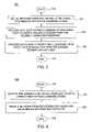
- FIG. 3illustrates a flowchart of a method 300 for signaling the network to enable peer-to-peer communication in a packet network, e.g., a VoIP network.
- Method 300starts in step 305 and proceeds to step 310 .
- the method 300signals the VoIP network using pre-defined signal, e.g., a predefined DTMF signal, to enable peer-to-peer communications.
- pre-defined signale.g., a predefined DTMF signal
- the networkwill remove itself from processing call setup message from the endpoint that originates the DTMF signal to request peer-to-peer communications.
- the methodproceeds with peer-to-peer communications using peer-to-peer signaling messages with the desired terminating endpoint.
- the methodproceeds with peer-to-peer communications using a peer-to-peer media path with the desired terminating endpoint.
- the methodends in step 340 . Since the feature is on a per call basis, once the peer-to-peer call is finished, the endpoint that requests the feature will revert back to the normal mode of communications, i.e. placing calls using the VoIP network again.
- FIG. 4illustrates a flowchart of a method 400 for disabling the packet network, e.g., a VoIP network, from processing signaling and media communication in a VoIP network.
- Method 400starts in step 405 and proceeds to step 410 .
- the method 400receives a pre-defined signal, e.g., a DTMF signal, from a calling endpoint to enable peer-to-peer communications on a per call basis.
- a pre-defined signale.g., a DTMF signal
- the methoddisables the VoIP network and associated network elements from processing signaling and media messages from the endpoint requesting peer-to-peer communications.
- the methodends in step 430 . Since the feature is on a per call basis, once the peer-to-peer call is finished, the endpoint that requests the feature will revert back to the normal mode of communications, i.e. placing calls using the VoIP network again.
- FIG. 5depicts a high level block diagram of a general purpose computer suitable for use in performing the functions described herein.
- the system 500comprises a processor element 502 (e.g., a CPU), a memory 504 , e.g., random access memory (RAM) and/or read only memory (ROM), a peer-to-peer communications between endpoints on a per call basis module 505 , and various input/output devices 506 (e.g., storage devices, including but not limited to, a tape drive, a floppy drive, a hard disk drive or a compact disk drive, a receiver, a transmitter, a speaker, a display, a speech synthesizer, an output port, and a user input device (such as a keyboard, a keypad, a mouse, and the like)).
- a processor element 502e.g., a CPU
- memory 504e.g., random access memory (RAM) and/or read only memory (ROM)
- ROMread only
- the present inventioncan be implemented in software and/or in a combination of software and hardware, e.g., using application specific integrated circuits (ASIC), a general purpose computer or any other hardware equivalents.
- ASICapplication specific integrated circuits
- the present peer-to-peer communications between endpoints on a per call basis module or process 505can be loaded into memory 504 and executed by processor 502 to implement the functions as discussed above.
- the present peer-to-peer communications between endpoints on a per call basis process 505 (including associated data structures) of the present inventioncan be stored on a computer readable medium or carrier, e.g., RAM memory, magnetic or optical drive or diskette and the like.
Landscapes
- Engineering & Computer Science (AREA)
- Computer Networks & Wireless Communication (AREA)
- Signal Processing (AREA)
- Multimedia (AREA)
- Business, Economics & Management (AREA)
- General Business, Economics & Management (AREA)
- Telephonic Communication Services (AREA)
- Data Exchanges In Wide-Area Networks (AREA)
Abstract
Description
Claims (20)
Priority Applications (4)
| Application Number | Priority Date | Filing Date | Title |
|---|---|---|---|
| US11/108,937US7583660B2 (en) | 2005-04-19 | 2005-04-19 | Method and apparatus for enabling peer-to-peer communication between endpoints on a per call basis |
| CA002544120ACA2544120A1 (en) | 2005-04-19 | 2006-04-19 | Method and apparatus for enabling peer-to-peer communication between endpoints on a per call basis |
| US12/550,038US8437337B2 (en) | 2005-04-19 | 2009-08-28 | Method and apparatus for enabling peer-to-peer communication between endpoints on a per call basis |
| US13/888,152US8885638B2 (en) | 2005-04-19 | 2013-05-06 | Method and apparatus for enabling peer-to-peer communication between endpoints on a per call basis |
Applications Claiming Priority (1)
| Application Number | Priority Date | Filing Date | Title |
|---|---|---|---|
| US11/108,937US7583660B2 (en) | 2005-04-19 | 2005-04-19 | Method and apparatus for enabling peer-to-peer communication between endpoints on a per call basis |
Related Child Applications (1)
| Application Number | Title | Priority Date | Filing Date |
|---|---|---|---|
| US12/550,038ContinuationUS8437337B2 (en) | 2005-04-19 | 2009-08-28 | Method and apparatus for enabling peer-to-peer communication between endpoints on a per call basis |
Publications (2)
| Publication Number | Publication Date |
|---|---|
| US20060233158A1 US20060233158A1 (en) | 2006-10-19 |
| US7583660B2true US7583660B2 (en) | 2009-09-01 |
Family
ID=37108380
Family Applications (3)
| Application Number | Title | Priority Date | Filing Date |
|---|---|---|---|
| US11/108,937Active2026-08-25US7583660B2 (en) | 2005-04-19 | 2005-04-19 | Method and apparatus for enabling peer-to-peer communication between endpoints on a per call basis |
| US12/550,038Active2027-07-06US8437337B2 (en) | 2005-04-19 | 2009-08-28 | Method and apparatus for enabling peer-to-peer communication between endpoints on a per call basis |
| US13/888,152Expired - LifetimeUS8885638B2 (en) | 2005-04-19 | 2013-05-06 | Method and apparatus for enabling peer-to-peer communication between endpoints on a per call basis |
Family Applications After (2)
| Application Number | Title | Priority Date | Filing Date |
|---|---|---|---|
| US12/550,038Active2027-07-06US8437337B2 (en) | 2005-04-19 | 2009-08-28 | Method and apparatus for enabling peer-to-peer communication between endpoints on a per call basis |
| US13/888,152Expired - LifetimeUS8885638B2 (en) | 2005-04-19 | 2013-05-06 | Method and apparatus for enabling peer-to-peer communication between endpoints on a per call basis |
Country Status (2)
| Country | Link |
|---|---|
| US (3) | US7583660B2 (en) |
| CA (1) | CA2544120A1 (en) |
Cited By (4)
| Publication number | Priority date | Publication date | Assignee | Title |
|---|---|---|---|---|
| US20090316691A1 (en)* | 2005-04-19 | 2009-12-24 | Marian Croak | Method and apparatus for enabling peer-to-peer communication between endpoints on a per call basis |
| US8238335B2 (en) | 2009-02-13 | 2012-08-07 | Avaya Inc. | Multi-route transmission of packets within a network |
| US8879464B2 (en) | 2009-01-29 | 2014-11-04 | Avaya Inc. | System and method for providing a replacement packet |
| US9369578B2 (en) | 2009-06-17 | 2016-06-14 | Avaya Inc. | Personal identification and interactive device for internet-based text and video communication services |
Families Citing this family (13)
| Publication number | Priority date | Publication date | Assignee | Title |
|---|---|---|---|---|
| US7773584B2 (en)* | 2006-06-13 | 2010-08-10 | At&T Intellectual Property I, L.P. | Method and apparatus for processing session initiation protocol messages associated with a voice over IP terminal |
| US10063392B2 (en) | 2007-08-21 | 2018-08-28 | At&T Intellectual Property I, L.P. | Methods and apparatus to select a voice over internet protocol (VOIP) border element |
| US9124603B2 (en)* | 2007-08-27 | 2015-09-01 | At&T Intellectual Property I., L.P. | Methods and apparatus to select a peered voice over internet protocol (VoIP) border element |
| US9258268B2 (en)* | 2007-08-27 | 2016-02-09 | At&T Intellectual Property, I., L.P. | Methods and apparatus to dynamically select a peered voice over internet protocol (VoIP) border element |
| US8520663B2 (en) | 2008-02-26 | 2013-08-27 | At&T Intellectual Property I, L. P. | Systems and methods to select peered border elements for an IP multimedia session based on quality-of-service |
| US8281369B2 (en)* | 2008-03-12 | 2012-10-02 | Avaya Inc. | Method and apparatus for creating secure write-enabled web pages that are associated with active telephone calls |
| US9525710B2 (en)* | 2009-01-29 | 2016-12-20 | Avaya Gmbh & Co., Kg | Seamless switch over from centralized to decentralized media streaming |
| DE102010005566B4 (en)* | 2009-01-29 | 2014-02-13 | Avaya Inc. | Seamless switching from centralized to decentralized media streaming |
| US7936746B2 (en)* | 2009-03-18 | 2011-05-03 | Avaya Inc. | Multimedia communication session coordination across heterogeneous transport networks |
| US20100265834A1 (en)* | 2009-04-17 | 2010-10-21 | Avaya Inc. | Variable latency jitter buffer based upon conversational dynamics |
| US8094556B2 (en)* | 2009-04-27 | 2012-01-10 | Avaya Inc. | Dynamic buffering and synchronization of related media streams in packet networks |
| US8800049B2 (en)* | 2009-08-26 | 2014-08-05 | Avaya Inc. | Licensing and certificate distribution via secondary or divided signaling communication pathway |
| US10129412B1 (en) | 2014-09-08 | 2018-11-13 | Whatsapp Inc. | Establishing and maintaining a VOIP call |
Citations (4)
| Publication number | Priority date | Publication date | Assignee | Title |
|---|---|---|---|---|
| US20040120502A1 (en)* | 2002-12-24 | 2004-06-24 | Strathmeyer Carl R. | Method and apparatus for implementing call processing in packet telephony networks |
| US6778491B1 (en)* | 2000-03-31 | 2004-08-17 | Alcatel | Method and system for providing redundancy for signaling link modules in a telecommunication system |
| US20060142010A1 (en)* | 2004-12-27 | 2006-06-29 | Newstep Networks Inc. | Method, system and apparatus for call path reconfiguration |
| US20080025295A1 (en)* | 1998-11-20 | 2008-01-31 | Elliott Isaac K | Voice over data telecommunications network architecture |
Family Cites Families (8)
| Publication number | Priority date | Publication date | Assignee | Title |
|---|---|---|---|---|
| US7002988B1 (en)* | 1998-12-04 | 2006-02-21 | Tekelec | Methods and systems for communicating SS7 messages over packet-based network using transport adapter layer interface |
| WO2002035784A1 (en)* | 2000-10-23 | 2002-05-02 | Radisys Corporation | Method and apparatus for common channel communication using a packet switched network |
| US6876646B1 (en)* | 2000-11-16 | 2005-04-05 | Nortel Networks Limited | Collecting information before a call |
| WO2002091692A1 (en)* | 2001-04-13 | 2002-11-14 | Girard Gregory D | Ditributed edge switching system for voice-over-packet multiservice network |
| US7369493B2 (en)* | 2003-10-28 | 2008-05-06 | At&T Corp. | Congestion control in an IP network |
| US7796520B2 (en)* | 2004-09-30 | 2010-09-14 | Avaya Canada Corp. | System and methods for announcing and locating services in a distributed peer-to-peer network |
| US8194640B2 (en)* | 2004-12-31 | 2012-06-05 | Genband Us Llc | Voice over IP (VoIP) network infrastructure components and method |
| US7583660B2 (en)* | 2005-04-19 | 2009-09-01 | At&T Corp. | Method and apparatus for enabling peer-to-peer communication between endpoints on a per call basis |
- 2005
- 2005-04-19USUS11/108,937patent/US7583660B2/enactiveActive
- 2006
- 2006-04-19CACA002544120Apatent/CA2544120A1/ennot_activeAbandoned
- 2009
- 2009-08-28USUS12/550,038patent/US8437337B2/enactiveActive
- 2013
- 2013-05-06USUS13/888,152patent/US8885638B2/ennot_activeExpired - Lifetime
Patent Citations (4)
| Publication number | Priority date | Publication date | Assignee | Title |
|---|---|---|---|---|
| US20080025295A1 (en)* | 1998-11-20 | 2008-01-31 | Elliott Isaac K | Voice over data telecommunications network architecture |
| US6778491B1 (en)* | 2000-03-31 | 2004-08-17 | Alcatel | Method and system for providing redundancy for signaling link modules in a telecommunication system |
| US20040120502A1 (en)* | 2002-12-24 | 2004-06-24 | Strathmeyer Carl R. | Method and apparatus for implementing call processing in packet telephony networks |
| US20060142010A1 (en)* | 2004-12-27 | 2006-06-29 | Newstep Networks Inc. | Method, system and apparatus for call path reconfiguration |
Cited By (6)
| Publication number | Priority date | Publication date | Assignee | Title |
|---|---|---|---|---|
| US20090316691A1 (en)* | 2005-04-19 | 2009-12-24 | Marian Croak | Method and apparatus for enabling peer-to-peer communication between endpoints on a per call basis |
| US8437337B2 (en) | 2005-04-19 | 2013-05-07 | At&T Intellectual Property Ii, L.P. | Method and apparatus for enabling peer-to-peer communication between endpoints on a per call basis |
| US8885638B2 (en) | 2005-04-19 | 2014-11-11 | At&T Intellectual Property Ii, L.P. | Method and apparatus for enabling peer-to-peer communication between endpoints on a per call basis |
| US8879464B2 (en) | 2009-01-29 | 2014-11-04 | Avaya Inc. | System and method for providing a replacement packet |
| US8238335B2 (en) | 2009-02-13 | 2012-08-07 | Avaya Inc. | Multi-route transmission of packets within a network |
| US9369578B2 (en) | 2009-06-17 | 2016-06-14 | Avaya Inc. | Personal identification and interactive device for internet-based text and video communication services |
Also Published As
| Publication number | Publication date |
|---|---|
| US20060233158A1 (en) | 2006-10-19 |
| CA2544120A1 (en) | 2006-10-19 |
| US8885638B2 (en) | 2014-11-11 |
| US20090316691A1 (en) | 2009-12-24 |
| US20130242981A1 (en) | 2013-09-19 |
| US8437337B2 (en) | 2013-05-07 |
Similar Documents
| Publication | Publication Date | Title |
|---|---|---|
| US8437337B2 (en) | Method and apparatus for enabling peer-to-peer communication between endpoints on a per call basis | |
| US8306190B2 (en) | Method and apparatus for enabling communications assistance for law enforcement act services | |
| EP1758341A1 (en) | Method and apparatus for providing internet protocol call transfer in communication networks | |
| US20070189469A1 (en) | Method and apparatus for providing location information for an emergency service | |
| EP1770947A1 (en) | Method and apparatus for providing endpoint and access independent virtual numbers | |
| US20100098067A1 (en) | Method and apparatus for routing calls to an alternative endpoint during network disruptions | |
| US7983404B1 (en) | Method and apparatus for providing presence status of multiple communication device types | |
| US20110188495A1 (en) | Method and apparatus for enabling dual tone multi-frequency signal processing in the core voice over internet protocol network | |
| CA2557094A1 (en) | Method and apparatus for providing customer configurable quality of service settings of customer premise based equipment | |
| CA2544154A1 (en) | Method and apparatus for enabling dynamic protocol interworking resolution with diverse endpoints | |
| US20100061365A1 (en) | Method and apparatus for providing extension management in voice over internet protocol customer premises | |
| US8570906B1 (en) | Method and apparatus for assigning a virtual number during porting of a primary number | |
| US9001987B2 (en) | Method and apparatus for providing dynamic international calling rates | |
| US20060146789A1 (en) | Method and apparatus for enabling personalized name identification in the calling name field | |
| EP1768344A1 (en) | Method and apparatus for dynamically establishing links between IP private branch exchanges | |
| US7974292B1 (en) | Method and apparatus for dynamically adjusting broadband access bandwidth | |
| US7852832B1 (en) | Method and apparatus for providing secure interface to externally hosted application servers | |
| US7555113B1 (en) | Method and apparatus for providing customer premise equipment based routing | |
| US7965700B1 (en) | Method and apparatus for enabling service indicators in a call control element | |
| US8693665B1 (en) | Method and apparatus for dynamically terminating calls over distinct access links | |
| HK1095021A (en) | Method and apparatus for routing calls to an alternative endpoint during network disruptions |
Legal Events
| Date | Code | Title | Description |
|---|---|---|---|
| AS | Assignment | Owner name:AT & T CORPORATION, NEW YORK Free format text:ASSIGNMENT OF ASSIGNORS INTEREST;ASSIGNORS:CROAK, MARIAN;ESLAMBOLCHI, HOSSEIN;REEL/FRAME:016648/0206;SIGNING DATES FROM 20050920 TO 20050921 | |
| STCF | Information on status: patent grant | Free format text:PATENTED CASE | |
| FPAY | Fee payment | Year of fee payment:4 | |
| AS | Assignment | Owner name:AT&T PROPERTIES, LLC, NEVADA Free format text:ASSIGNMENT OF ASSIGNORS INTEREST;ASSIGNOR:AT&T CORP.;REEL/FRAME:038167/0239 Effective date:20160331 Owner name:AT&T INTELLECTUAL PROPERTY II, L.P., GEORGIA Free format text:ASSIGNMENT OF ASSIGNORS INTEREST;ASSIGNOR:AT&T PROPERTIES, LLC;REEL/FRAME:038167/0276 Effective date:20160331 Owner name:AT&T CORP., NEW YORK Free format text:CORRECTIVE ASSIGNMENT TO CORRECT THE ASSIGNEE NAME PREVIOUSLY RECORDED AT REEL: 016648 FRAME: 0206. ASSIGNOR(S) HEREBY CONFIRMS THE ASSIGNMENT;ASSIGNORS:CROAK, MARIAN;ESLAMBOLCHI, HOSSEIN;SIGNING DATES FROM 20050920 TO 20050921;REEL/FRAME:038324/0621 | |
| AS | Assignment | Owner name:GENESIS STAR MANAGEMENT LIMITED, VIRGIN ISLANDS, B Free format text:ASSIGNMENT OF ASSIGNORS INTEREST;ASSIGNOR:AT&T INTELLECTUAL PROPERTY II, L.P.;REEL/FRAME:038640/0415 Effective date:20160426 | |
| FPAY | Fee payment | Year of fee payment:8 | |
| MAFP | Maintenance fee payment | Free format text:PAYMENT OF MAINTENANCE FEE, 12TH YEAR, LARGE ENTITY (ORIGINAL EVENT CODE: M1553); ENTITY STATUS OF PATENT OWNER: LARGE ENTITY Year of fee payment:12 |