US7582911B2 - LED luminaire - Google Patents
LED luminaireDownload PDFInfo
- Publication number
- US7582911B2 US7582911B2US11/496,341US49634106AUS7582911B2US 7582911 B2US7582911 B2US 7582911B2US 49634106 AUS49634106 AUS 49634106AUS 7582911 B2US7582911 B2US 7582911B2
- Authority
- US
- United States
- Prior art keywords
- lighting apparatus
- led
- power
- module
- driver
- Prior art date
- Legal status (The legal status is an assumption and is not a legal conclusion. Google has not performed a legal analysis and makes no representation as to the accuracy of the status listed.)
- Expired - Fee Related
Links
Images


Classifications
- F—MECHANICAL ENGINEERING; LIGHTING; HEATING; WEAPONS; BLASTING
- F21—LIGHTING
- F21V—FUNCTIONAL FEATURES OR DETAILS OF LIGHTING DEVICES OR SYSTEMS THEREOF; STRUCTURAL COMBINATIONS OF LIGHTING DEVICES WITH OTHER ARTICLES, NOT OTHERWISE PROVIDED FOR
- F21V29/00—Protecting lighting devices from thermal damage; Cooling or heating arrangements specially adapted for lighting devices or systems
- F21V29/50—Cooling arrangements
- F21V29/70—Cooling arrangements characterised by passive heat-dissipating elements, e.g. heat-sinks
- F21V29/74—Cooling arrangements characterised by passive heat-dissipating elements, e.g. heat-sinks with fins or blades
- F—MECHANICAL ENGINEERING; LIGHTING; HEATING; WEAPONS; BLASTING
- F21—LIGHTING
- F21K—NON-ELECTRIC LIGHT SOURCES USING LUMINESCENCE; LIGHT SOURCES USING ELECTROCHEMILUMINESCENCE; LIGHT SOURCES USING CHARGES OF COMBUSTIBLE MATERIAL; LIGHT SOURCES USING SEMICONDUCTOR DEVICES AS LIGHT-GENERATING ELEMENTS; LIGHT SOURCES NOT OTHERWISE PROVIDED FOR
- F21K9/00—Light sources using semiconductor devices as light-generating elements, e.g. using light-emitting diodes [LED] or lasers
- F—MECHANICAL ENGINEERING; LIGHTING; HEATING; WEAPONS; BLASTING
- F21—LIGHTING
- F21S—NON-PORTABLE LIGHTING DEVICES; SYSTEMS THEREOF; VEHICLE LIGHTING DEVICES SPECIALLY ADAPTED FOR VEHICLE EXTERIORS
- F21S4/00—Lighting devices or systems using a string or strip of light sources
- F21S4/10—Lighting devices or systems using a string or strip of light sources with light sources attached to loose electric cables, e.g. Christmas tree lights
- F—MECHANICAL ENGINEERING; LIGHTING; HEATING; WEAPONS; BLASTING
- F21—LIGHTING
- F21V—FUNCTIONAL FEATURES OR DETAILS OF LIGHTING DEVICES OR SYSTEMS THEREOF; STRUCTURAL COMBINATIONS OF LIGHTING DEVICES WITH OTHER ARTICLES, NOT OTHERWISE PROVIDED FOR
- F21V23/00—Arrangement of electric circuit elements in or on lighting devices
- F21V23/003—Arrangement of electric circuit elements in or on lighting devices the elements being electronics drivers or controllers for operating the light source, e.g. for a LED array
- F21V23/007—Arrangement of electric circuit elements in or on lighting devices the elements being electronics drivers or controllers for operating the light source, e.g. for a LED array enclosed in a casing
- F—MECHANICAL ENGINEERING; LIGHTING; HEATING; WEAPONS; BLASTING
- F21—LIGHTING
- F21V—FUNCTIONAL FEATURES OR DETAILS OF LIGHTING DEVICES OR SYSTEMS THEREOF; STRUCTURAL COMBINATIONS OF LIGHTING DEVICES WITH OTHER ARTICLES, NOT OTHERWISE PROVIDED FOR
- F21V23/00—Arrangement of electric circuit elements in or on lighting devices
- F21V23/04—Arrangement of electric circuit elements in or on lighting devices the elements being switches
- F21V23/0442—Arrangement of electric circuit elements in or on lighting devices the elements being switches activated by means of a sensor, e.g. motion or photodetectors
- F21V23/0471—Arrangement of electric circuit elements in or on lighting devices the elements being switches activated by means of a sensor, e.g. motion or photodetectors the sensor detecting the proximity, the presence or the movement of an object or a person
- F—MECHANICAL ENGINEERING; LIGHTING; HEATING; WEAPONS; BLASTING
- F21—LIGHTING
- F21V—FUNCTIONAL FEATURES OR DETAILS OF LIGHTING DEVICES OR SYSTEMS THEREOF; STRUCTURAL COMBINATIONS OF LIGHTING DEVICES WITH OTHER ARTICLES, NOT OTHERWISE PROVIDED FOR
- F21V29/00—Protecting lighting devices from thermal damage; Cooling or heating arrangements specially adapted for lighting devices or systems
- F21V29/50—Cooling arrangements
- F21V29/70—Cooling arrangements characterised by passive heat-dissipating elements, e.g. heat-sinks
- F21V29/83—Cooling arrangements characterised by passive heat-dissipating elements, e.g. heat-sinks the elements having apertures, ducts or channels, e.g. heat radiation holes
- H—ELECTRICITY
- H02—GENERATION; CONVERSION OR DISTRIBUTION OF ELECTRIC POWER
- H02G—INSTALLATION OF ELECTRIC CABLES OR LINES, OR OF COMBINED OPTICAL AND ELECTRIC CABLES OR LINES
- H02G3/00—Installations of electric cables or lines or protective tubing therefor in or on buildings, equivalent structures or vehicles
- H02G3/02—Details
- H02G3/08—Distribution boxes; Connection or junction boxes
- H02G3/18—Distribution boxes; Connection or junction boxes providing line outlets
- H02G3/20—Ceiling roses or other lighting sets
- F—MECHANICAL ENGINEERING; LIGHTING; HEATING; WEAPONS; BLASTING
- F21—LIGHTING
- F21S—NON-PORTABLE LIGHTING DEVICES; SYSTEMS THEREOF; VEHICLE LIGHTING DEVICES SPECIALLY ADAPTED FOR VEHICLE EXTERIORS
- F21S8/00—Lighting devices intended for fixed installation
- F21S8/02—Lighting devices intended for fixed installation of recess-mounted type, e.g. downlighters
- F21S8/024—Lighting devices intended for fixed installation of recess-mounted type, e.g. downlighters intended to be recessed in a wall or like vertical structure, e.g. building facade
- F—MECHANICAL ENGINEERING; LIGHTING; HEATING; WEAPONS; BLASTING
- F21—LIGHTING
- F21S—NON-PORTABLE LIGHTING DEVICES; SYSTEMS THEREOF; VEHICLE LIGHTING DEVICES SPECIALLY ADAPTED FOR VEHICLE EXTERIORS
- F21S8/00—Lighting devices intended for fixed installation
- F21S8/03—Lighting devices intended for fixed installation of surface-mounted type
- F21S8/033—Lighting devices intended for fixed installation of surface-mounted type the surface being a wall or like vertical structure, e.g. building facade
- F21S8/035—Lighting devices intended for fixed installation of surface-mounted type the surface being a wall or like vertical structure, e.g. building facade by means of plugging into a wall outlet, e.g. night light
- F—MECHANICAL ENGINEERING; LIGHTING; HEATING; WEAPONS; BLASTING
- F21—LIGHTING
- F21V—FUNCTIONAL FEATURES OR DETAILS OF LIGHTING DEVICES OR SYSTEMS THEREOF; STRUCTURAL COMBINATIONS OF LIGHTING DEVICES WITH OTHER ARTICLES, NOT OTHERWISE PROVIDED FOR
- F21V11/00—Screens not covered by groups F21V1/00, F21V3/00, F21V7/00 or F21V9/00
- F—MECHANICAL ENGINEERING; LIGHTING; HEATING; WEAPONS; BLASTING
- F21—LIGHTING
- F21V—FUNCTIONAL FEATURES OR DETAILS OF LIGHTING DEVICES OR SYSTEMS THEREOF; STRUCTURAL COMBINATIONS OF LIGHTING DEVICES WITH OTHER ARTICLES, NOT OTHERWISE PROVIDED FOR
- F21V19/00—Fastening of light sources or lamp holders
- F21V19/001—Fastening of light sources or lamp holders the light sources being semiconductors devices, e.g. LEDs
- F—MECHANICAL ENGINEERING; LIGHTING; HEATING; WEAPONS; BLASTING
- F21—LIGHTING
- F21V—FUNCTIONAL FEATURES OR DETAILS OF LIGHTING DEVICES OR SYSTEMS THEREOF; STRUCTURAL COMBINATIONS OF LIGHTING DEVICES WITH OTHER ARTICLES, NOT OTHERWISE PROVIDED FOR
- F21V33/00—Structural combinations of lighting devices with other articles, not otherwise provided for
- F21V33/006—General building constructions or finishing work for buildings, e.g. roofs, gutters, stairs or floors; Garden equipment; Sunshades or parasols
- F—MECHANICAL ENGINEERING; LIGHTING; HEATING; WEAPONS; BLASTING
- F21—LIGHTING
- F21Y—INDEXING SCHEME ASSOCIATED WITH SUBCLASSES F21K, F21L, F21S and F21V, RELATING TO THE FORM OR THE KIND OF THE LIGHT SOURCES OR OF THE COLOUR OF THE LIGHT EMITTED
- F21Y2115/00—Light-generating elements of semiconductor light sources
- F21Y2115/10—Light-emitting diodes [LED]
- H—ELECTRICITY
- H01—ELECTRIC ELEMENTS
- H01L—SEMICONDUCTOR DEVICES NOT COVERED BY CLASS H10
- H01L2224/00—Indexing scheme for arrangements for connecting or disconnecting semiconductor or solid-state bodies and methods related thereto as covered by H01L24/00
- H01L2224/01—Means for bonding being attached to, or being formed on, the surface to be connected, e.g. chip-to-package, die-attach, "first-level" interconnects; Manufacturing methods related thereto
- H01L2224/42—Wire connectors; Manufacturing methods related thereto
- H01L2224/47—Structure, shape, material or disposition of the wire connectors after the connecting process
- H01L2224/48—Structure, shape, material or disposition of the wire connectors after the connecting process of an individual wire connector
- H01L2224/4805—Shape
- H01L2224/4809—Loop shape
- H01L2224/48091—Arched
- H—ELECTRICITY
- H01—ELECTRIC ELEMENTS
- H01L—SEMICONDUCTOR DEVICES NOT COVERED BY CLASS H10
- H01L2224/00—Indexing scheme for arrangements for connecting or disconnecting semiconductor or solid-state bodies and methods related thereto as covered by H01L24/00
- H01L2224/01—Means for bonding being attached to, or being formed on, the surface to be connected, e.g. chip-to-package, die-attach, "first-level" interconnects; Manufacturing methods related thereto
- H01L2224/42—Wire connectors; Manufacturing methods related thereto
- H01L2224/47—Structure, shape, material or disposition of the wire connectors after the connecting process
- H01L2224/48—Structure, shape, material or disposition of the wire connectors after the connecting process of an individual wire connector
- H01L2224/481—Disposition
- H01L2224/48151—Connecting between a semiconductor or solid-state body and an item not being a semiconductor or solid-state body, e.g. chip-to-substrate, chip-to-passive
- H01L2224/48221—Connecting between a semiconductor or solid-state body and an item not being a semiconductor or solid-state body, e.g. chip-to-substrate, chip-to-passive the body and the item being stacked
- H01L2224/48245—Connecting between a semiconductor or solid-state body and an item not being a semiconductor or solid-state body, e.g. chip-to-substrate, chip-to-passive the body and the item being stacked the item being metallic
- H01L2224/48247—Connecting between a semiconductor or solid-state body and an item not being a semiconductor or solid-state body, e.g. chip-to-substrate, chip-to-passive the body and the item being stacked the item being metallic connecting the wire to a bond pad of the item
- H—ELECTRICITY
- H01—ELECTRIC ELEMENTS
- H01L—SEMICONDUCTOR DEVICES NOT COVERED BY CLASS H10
- H01L2924/00—Indexing scheme for arrangements or methods for connecting or disconnecting semiconductor or solid-state bodies as covered by H01L24/00
- H01L2924/30—Technical effects
- H01L2924/301—Electrical effects
- H01L2924/3025—Electromagnetic shielding
Definitions
- the present inventionrelates generally to light emitting diode (LED) lighting devices and more particularly to a luminaire having a heat conductive body.
- LEDlight emitting diode
- LEDslight emitting diodes
- LEDsare relatively inexpensive, operate at low voltage, and have long operating lifetimes. Additionally, LEDs consume relatively little power and are compact. These attributes make LEDs particularly desirable and well suited for many applications.
- the brightness of the light emitted by an LEDcan be increased by increasing the electrical current supplied to the LED, increased current also increases the junction temperature of the LED. Increased junction temperature may reduce the efficiency and the lifetime of the LED. For example, it has been noted that for every 10° C. increase in temperature above a specified temperature, the operating lifetime of silicone and gallium arsenide drops by a factor of 2.5-3. LEDs are often constructed of semiconductor materials that share many similar properties with silicone and gallium arsenide.
- a lighting apparatuscomprising a light emitting diode (LED) module.
- the LED modulehas at least one LED, a dielectric member, and a plurality of electrically conductive contacts disposed on the dielectric member. The contacts are configured to mount the at least one LED to supply electrical current to the LED.
- the apparatusfurther comprises a heat conductive member and an electrical junction box.
- the junction boxhas a plurality of sides defining a cavity therewithin, and at least one of the sides has a knockout port configured to selectively provide access to the cavity.
- the LED moduleis in thermal communication with the heat conductive member, and the heat conductive member is attached to and in thermal communication with the junction box so that heat from the LED flows through the heat conductive member to the junction box.
- the heat conducting memberis shaped generally complementary to the junction box front edge such that the heat conducting member is in thermal communication with at least a portion of the front edge.
- the lighting apparatusfurther comprises a sensor for detecting a desired environmental parameter.
- the apparatusis further configured to send a corresponding signal to the driver, which is configured to drive the LEDs according to a desired lighting strategy in response to the signal.
- a method of making a lighting apparatuscomprises at least one LED, a dielectric member, and a plurality of electrically conductive contacts disposed on the dielectric member. The contacts are configured to mount the at least one LED to supply electrical current to the LED.
- a heat conductive memberis provided in thermal communication with the LED module.
- An electrical junction boxhaving a plurality of sides defining a cavity and a front edge is provided. The heat conductive member is mounted onto the electrical junction box so that the heat conductive member is in thermal communication with the junction box.
- the present inventionprovides a lighting apparatus, comprising: an LED module, a heat conductive member, and a power driver.
- the LED modulehas at least one LED, a dielectric member, and a plurality of electrically conductive contacts disposed on the dielectric member. The contacts are configured to mount the at least one LED so that an electrical current path is defined between a first contact and a second contact, and the at least one LED is disposed along the current path.
- the heat conductive memberhas a first side and a second side.
- the power driveris adapted to receive an electrical input power, condition the power to a desired power configuration, and output conditioned power.
- the LED moduleis attached to the first side of the heat conductive member and the power driver is attached to the second side of the heat conductive member, and the driver is electrically connected to the LED module so that conditioned power is supplied across the first and second contacts.
- a pair of fastenersconnect the LED module to the first side of the heat conductive member.
- a fastenerengages respective ones of the first and second contacts of the LED module, and herein electrical power from the driver is delivered through the fasteners to the LED module.
- the drivercomprises a pair of receivers adapted to output conditioned power, and the fasteners are adapted to engage the driver receivers so that power is supplied directly from the driver to the fasteners and further to the LED module.
- FIG. 1is a perspective view of an LED module having features in accordance with an embodiment.
- FIG. 2is a schematic side view of a typical pre-packaged LED lamp.
- FIG. 3is a top plan view of the LED module of FIG. 1 .
- FIG. 4is a side plan view of the apparatus of FIG. 3 .
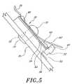
- FIG. 5is a close-up side view of the apparatus of FIG. 3 mounted on a heat conductive member.
- FIG. 6is another sectional side view of the apparatus of FIG. 3 mounted onto a heat conductive flat surface.
- FIG. 7is a side plan view of an LED module having features in accordance with another embodiment.
- FIG. 8is a side plan view of another LED module having features in accordance with yet another embodiment.
- FIG. 9is a plan view of yet another embodiment of an LED module.
- FIG. 10shows the LED module of FIG. 9 including a masking layer.
- FIG. 11is a sectional view of the LED module of FIG. 10 taken along line 11 - 11 .
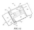
- FIG. 12is a perspective view of the LED module of FIG. 10 , showing a reflective strip included thereon.
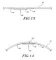
- FIG. 13is a side view of the LED module of FIG. 9 mounted on a flat surface.
- FIG. 14is a close-up side view of the LED module of FIG. 9 mounted on a curving surface.
- FIG. 15is a perspective view of a channel illumination apparatus incorporating LED modules.
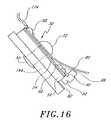
- FIG. 16is a cross-sectional side view taken along line 16 - 16 of FIG. 14 .
- FIG. 17is a partial view of a wall of the apparatus of FIG. 15 , taken along line 17 - 17 .
- FIG. 18is a top view of an LED module mounted to a wall of the apparatus of FIG. 15 .
- FIG. 19shows a plurality of modules such as the LED module of FIG. 9 wired together.
- FIG. 20is a circuit diagram showing the arrangement of FIG. 19 connected to a power supply.
- FIG. 21is a side view of a plurality of wired-together LED modules such as the LED module of FIG. 9 , arranged on a dispensing roll.
- FIG. 22shows wired-together modules from the dispensing roll of FIG. 21 being installed into a channel illumination apparatus.
- FIG. 23is a plan view of a plurality of wired-together LED modules such as the LED module of FIG. 9 , arranged within a box dispenser.
- FIG. 24is a plan view of an LED module having modular wire connectors.
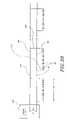
- FIG. 25Ais an exploded view of an LED luminaire configured for use with an electrical junction box.
- FIG. 25Bis an exploded view of another embodiment of an LED luminaire configured for use with an electrical junction box.
- FIG. 26shows an LED module configured to be used with the device of FIG. 25 .
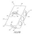
- FIG. 27Ais a perspective view of the assembled device of FIG. 25 .
- FIG. 27Bis another perspective view of the assembled device of FIG. 25 showing the mounted LEDs.
- FIG. 28is a side elevational view of a lighting device configured to mount in an electrical junction box.
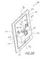
- FIG. 29is a rear perspective view of the device of FIG. 28 .
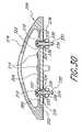
- FIG. 30is a cross sectional view of the device of FIG. 29 taken along the line 30 - 30 .
- FIG. 31is a side elevational view of another embodiment of a lighting device.
- FIG. 32is a perspective view of another embodiment of an LED luminaire.
- FIG. 33is an exploded view of the embodiment shown in FIG. 32 .
- the LED module 30includes five pre-packaged LEDs 32 arranged along a front edge of the module 30 . It is to be understood, however, that LED modules can be constructed having any number of LEDs 32 mounted in any desired configuration.
- a typical LED package 32includes a diode chip 34 encased within a resin body 36 .
- the LED package 32typically has a focusing lens portion 38 on the body 36 and a pair of leads 40 , 44 , one of which is negative and the other positive.
- the negative lead 40connects to an anode side 42 of the diode chip 34 and the positive lead 44 connects to a cathode side 46 of the diode chip 34 .
- the positive lead 44preferably includes a reflector portion 48 to help direct light from the diode 34 to the lens portion 38 .
- the LED module 30preferably comprises the five pre-packaged LED lamps 32 mounted in a linear array on a circuit board 50 and electrically connected in series.
- the LED lamps 32may comprise Hewlett Packard model HLMT-PL00 lamps, which employ pre-packaged aluminum indium gallium phosphide (AlInGaP) chips 34 .
- AlInGaPaluminum indium gallium phosphide
- each of the pre-packaged LEDsis substantially identical so that they emit the same color of light. It is to be understood, however, that nonidentical LEDs may be used to achieve certain desired lighting effects.
- the illustrated circuit board 50preferably is about 0.05 inches thick, 1 inch long and 0.5 inch wide. It includes three layers: a copper contact layer 52 , an epoxy dielectric layer 54 and an aluminum main body layer 56 .
- the copper contact layer 52is made up of a series of six elongate and generally parallel flat copper plates 60 that are adapted to attach to the leads 40 , 44 of the LEDs 32 .
- Each of the copper contacts 60is electrically insulated from the other copper contacts 60 by the dielectric layer 54 .
- the copper contacts 60are substantially coplanar.
- the pre-packaged LEDs 32are attached to one side of the circuit board 50 , with the body portion 36 of each LED generally abutting a side of the circuit board 50 .
- the LED lens portion 38is thus pointed outwardly so as to direct light in a direction substantially coplanar with the circuit board 50 .
- the LED leads 40 , 44are soldered onto the contacts 60 in a manner to create a series array of LEDs. Excess material from the leads of the individual pre-packaged LED lamps may be removed, if desired.
- Each of the contacts 60except for the first and last contact 62 , 64 , have both a negative lead 40 and a positive lead 44 attached thereto.
- One of the first and last contacts 62 , 64has only a negative lead 40 attached thereto; the other has only a positive lead 44 attached thereto.
- a bonding area 66 of the contactsaccommodates the leads 40 , 44 , which are preferably bonded to the contact 60 with solder 68 ; however, each contact 60 preferably has a surface area much larger than is required for bonding in the bonding area 66 .
- the enlarged contact surface areaallows each contact 60 to operate as a heat sink, efficiently absorbing heat from the LED leads 40 , 44 .
- the contacts 60are shaped to be as large as possible while still fitting upon the circuit board 50 .
- the dielectric layer 54preferably has strong electrical insulation properties but also relatively high heat conductance properties, and is preferably as thin as practicable.
- the dielectric layer 54comprises a layer of Thermagon® epoxy about 0.002 inches thick.
- the dielectric layer 54can be used for various materials and thicknesses. Generally, the lower the thermal conductivity of the material used for the dielectric layer, the thinner that dielectric layer should be in order to maximize the heat transfer properties of the module. Nevertheless, even when a material such as Thermagon® epoxy, which has high thermal conductivity, is used, the dielectric layer is preferably as thin as practicable in order to minimize thermal resistance. Certain ceramic materials, such as beryllium oxide and aluminum nitride, are electrically non-conductive but highly thermally conductive. Such materials, and still other materials, can also be acceptably used for the dielectric layer.
- the main body 56makes up the bulk of the thickness of the circuit board 50 and preferably comprises a flat aluminum plate.
- the main body 56functions as a heat conduit, absorbing heat from the contacts 60 through the dielectric layer 54 in order to conduct heat away from the LEDs 32 .
- the main body 56acts as a common heat conduit, absorbing heat from all of the contacts 60 .
- the surface area of the main body 56is about the same as the combined surface area of all of the individual contacts 60 .
- the main body 56can be significantly larger than shown in the illustrated embodiment, but its relatively compact shape is preferable in order to increase versatility when mounting the light module 30 . Additionally, the main body 56 is relatively rigid and provides structural support for the lighting module 30 .
- the main body 56is made of aluminum, which has high thermal conductance properties and is easy to work with during manufacture. It is to be understood, however, that any material having advantageous thermal conductance properties, such as, for example, having thermal conductivity greater than about 75 watts per meter per Kelvin (W/m*K), or greater than about 100 W/m*K, would be acceptable.
- a pair of holes 70are formed through the circuit board 50 and are adapted to accommodate a pair of aluminum pop rivets 72 .
- the pop rivets 72hold the circuit board 50 securely onto a heat conductive mount member 76 .
- the mount member 76functions as or communicates with a heat sink.
- power supply wires 78are attached across the first and last contacts 62 , 64 of the circuit board 50 so that electrical current is provided to the series-connected LEDs 32 .
- the power supplyis preferably a 12-volt system and may be AC, DC or any other suitable power supply. A 12-volt AC system may be fully rectified. In another embodiment, the power supply is configured to supply constant current to the circuit board.
- the small size of the LED module 30provides versatility so that a plurality of modules can be mounted at various places and in various configurations. For instance, some applications will include only a single module for a particular lighting application, while other lighting applications will employ a plurality of modules electrically connected in parallel relative to each other.
- any number of LEDscan be included in one module.
- some modulesmay use two LEDs, while other modules may use 10 or more LEDs.
- One manner of determining the number of LEDs to include in a single moduleis to first determine the desired operating voltage of a single LED of the module and also the voltage of the power supply. The number of LEDs desired for the module is then roughly equal to the voltage of the power supply divided by the operating voltage of each of the LEDs.
- the present LED module 30rapidly conducts heat away from the diode chip 34 of each LED 32 so as to permit the LEDs 32 to be operated in regimes that exceed normal operating parameters of the pre-packaged LEDs 32 .
- the heat sinksallow the LED circuit to be driven in a continuous, non-pulsed manner at a higher long-term electrical current than is possible for typical LED mounting configurations. This operating current is substantially greater than manufacturer-recommended maximums. The optical emission of the LEDs at the higher current is also markedly greater than at manufacturer-suggested maximum currents.
- the heat transfer arrangement of the LED modules 30is especially advantageous for pre-packaged LEDs 32 having relatively small packaging and for single-diode LED lamps.
- the HLMT-PL00 model LED lamps used in the illustrated embodimentemploy only a single diode, but since heat can be drawn efficiently from that single diode through the leads and circuit board and into the heat sink, the diode can be run at a higher current than such LEDs are traditionally operated. At such a current, the single-diode LED shines brighter than many LED lamps that employ two or more diodes and which are brighter than a single-diode lamp during traditional operation.
- pre-packaged LED lamps having multiple diodescan also be advantageously employed with the present modular mounting arrangement. It is also to be understood that the relatively small packaging of the model HLMT-PL00 lamps aids in heat transfer by allowing the heat sink to be attached to the leads closer to the diode chip.
- a first reflective layer 80is preferably attached immediately on top of the contacts 60 of the circuit board 50 and is held in position by the rivets 72 .
- the first reflector 80preferably extends outwardly beyond the LEDs 32 .
- the reflective materialpreferably comprises an electrically non-conductive film such as visible mirror film, which is available from 3M.
- a second reflective layer 82is preferably attached to the mount member 76 at a point immediately adjacent the LED lamps 32 .
- the second strip 82is preferably bonded to the mount surface 76 using adhesive in a manner known in the art.
- the first reflective strip 80is preferably bent so as to form a convex reflective trough about the LEDs 32 .
- the convex troughis adapted to direct light rays emitted by the LEDs 32 outward with a minimum of reflections between the reflector strips 80 , 82 . Additionally, light from the LEDs is limited to being directed in a specified general direction by the reflecting films 80 , 82 .
- the circuit board 50can be mounted directly to any mount surface 76 .
- the aluminum main body portion 56may be of reduced thickness or may be formed of a softer metal so that the module 30 can be at least partially deformed by a user. In this manner, the module 30 can be adjusted to fit onto various surfaces, whether they are flat or curved. By being able to adjust the fit of the module to the surface, the shared contact surface between the main body and the adjacent heat sink mount surface is maximized, thus improving heat transfer properties.
- Additional embodimentscan use fasteners other than rivets to hold the module into place on the mount surface/heat sink material. These additional fasteners can include any known fastening means such as welding, heat-conductive adhesives, and the like.
- an LED module 86comprises a series of elongate, flat contacts 88 similar to those described above with reference to FIG. 3 .
- the contacts 88are mounted directly onto the main body portion 89 .
- the main body 89comprises a rigid, substantially flat ceramic plate.
- the ceramic platemakes up the bulk of the circuit board and provides structural support for the contacts 88 .
- the ceramic platehas a surface area about the same as the combined surface area of the contacts.
- the plateis large enough to provide structural support for the contacts 88 and to conduct heat away from each of the contacts 88 , but is small enough to allow the module 86 to be relatively small and easy to work with.
- the ceramic plate 89is preferably electrically non-conductive but has high heat conductivity.
- the contacts 88are electrically insulated relative to each other, but heat from the contacts 88 is readily transferred to the ceramic plate 89 and into an adjacent heat sink.
- the LED module 90comprises a circuit board 92 having features substantially similar to the circuit board 50 described above with reference to FIG. 3 .
- the diode portion 94 of an LED 96is mounted substantially directly onto the contacts 60 of the lighting module 90 . In this manner, any thermal resistance from leads of pre-packaged LEDs is eliminated by transferring heat directly from the diode 94 onto each heat sink contact 60 , from which the heat is conducted to the main body 56 and then out of the module 90 . In this configuration, heat transfer properties are yet further improved.
- the LED module 100preferably comprises a circuit board 50 which includes a contact layer 52 , a dielectric layer 54 , and a main body layer 56 .
- the contact layer 52includes a series of electrical traces and contacts, as will be discussed in further detail below.
- the dielectric layer 54electrically insulates the traces and contacts relative to one another.
- the main body layer 56provides support and helps thermally conduct heat away from the contact layer 52 and dielectric layer 54 .
- the contact layer 52comprises a series of six contacts 60 , which comprise elongate and, generally parallel electrically conductive flat plates. Leads 40 , 44 of five LEDs 32 attach to the contacts 60 so as to form a linear array of the five prepackaged LEDs 32 , which are arranged in series relative to one another.
- First and second elongate power traces 102 , 104extend in a direction generally transverse to the parallel plates 60 , but parallel to the series array.
- the power traces 102 , 104comprise conductive material, and are electrically insulated from each other and the contacts by the dielectric layer 54 .
- Secondary connecting portions 106are also provided adjacent first and second side edges 110 , 112 of the circuit board 50 . The secondary connecting portions 106 are also electrically insulated from the contacts 60 and power traces 102 , 104 by the dielectric layer 54 .
- a first connector trace 118extends between the first contact 62 and a first end 120 of the first power trace 102 .
- a second connection trace 122extends between the last contact 64 and a second end 124 of the second power trace 104 .
- the connector traces 118 , 122place their respective contacts 62 , 64 into electrical communication with the corresponding power traces 102 , 104 .
- FIG. 10shows a view similar to FIG. 9 , except that a thin mask layer 126 is applied to selected portions of a top face 130 of the circuit board 50 .
- FIG. 11is a sectional view showing layers of the module 100 .
- the masking layer 126covers certain portions of the contacts 60 and traces 102 , 104 , 118 , 122 . These covered portions are depicted in phantom lines in FIG. 10 . Other portions of the contacts and traces are left uncovered in order to function as solder points so as to facilitate electrical connection with certain other components.
- the masking layer 126fulfills an aesthetic function and also protects areas of the contacts that are not used for electrical connections from environmental factors.
- the mask layer 126covers a portion of each of the contacts 60 .
- each of the contacts 60has a connecting area 66 which is not covered and which accommodates the leads 40 , 44 of the associated LEDs 32 .
- a connecting portion 132 of both the first and last contacts 62 , 64is also not covered by the mask layer 126 .
- the mask layer 126covers portions of each power trace 102 , 104 .
- a first end connecting portion 134 of each power trace 102 , 104is provided at the end closest to the first side edge 110 of the circuit board 50 .
- a second end connecting portion 136 of each power trace 102 , 104is provided at the end closest to the second side edge 112 of the circuit board 50 .
- the mask layer 126does not cover the power traces in the connecting portions 134 , 136 .
- First and second flexible conductorssuch as wires 114 , 116 (see FIG. 19 ) can be connected to the connecting portions 134 , 136 in order to supply power to the LED array.
- a layer of adhesive tape 140is attached to a bottom face 142 of the LED module 100 .
- the tape 140preferably extends across the bottom face 142 and outwardly from the first and second opposing side edges 110 , 112 of the circuit board 50 , creating first and second flaps or ears 144 , 146 of the tape 140 .
- the tape 140preferably is malleable and can be bent easily.
- a backing 148is provided on the tape 140 . The backing 148 can be peeled away to expose an adhesive layer, and the tape/module can be applied to a desired surface in a manner so that the module 100 is held securely in place on that surface.
- a reflective layer 80is also preferably attached to the circuit board 50 .
- the reflective layer 80is preferably held onto the circuit board 50 by a strip of adhesive operating between the mask layer 126 and the reflective cover 80 .
- the reflective cover 80preferably extends over the LEDs 32 in a manner as discussed above.
- the adhesive tape 140secures a module 100 onto either a flat or a curved surface 76 .
- the flaps or ears of the tapewill still be able to securely attach the module onto the curved surface.
- the tape layer 140can be provided with or without the ears 144 , 146 , and that the ears can be of any desired size and shape.
- the adhesive tape 140preferably has properties that complement the heat transfer properties of the module.
- the tape 140comprises an aluminum tape having a heat-conductive adhesive applied thereto.
- the aluminum tapeis capable of conforming to a curving or undulating surface, and also efficiently transfers heat from the module to the surface onto which it is attached. This aspect proves especially valuable when the module 100 is affixed to a curving heat sink surface 76 , as shown in FIG. 14 , and a large proportion of the module's circuit board 50 does not directly contact the curving surface. In such an instance, heat from the circuit board 50 flows through the ears 144 , 146 to the heat sink 76 .
- the LED module's main bodyis formed of a bendable material, which allows the module to fit more closely and easily to a curved wall surface.
- an LED module having features of the embodiments described abovecan be used in many applications such as, for example, indoor and outdoor decorative lighting, commercial lighting, spot lighting, and even room lighting. Such LED modules can also be used in applications using a plurality of such modules to appropriately light a lighting apparatus such as a channel illumination device 160 (see FIG. 15 ).
- Channel illumination devicesare frequently used for signage including borders and lettering.
- a wall structureoutlines a desired shape to be illuminated, with one or more channels defined between the walls.
- a light sourceis mounted within the channel and a planar translucent diffuser is usually arranged at the top edges of the walls so as to enclose the channel. In this manner, a desired shape can be illuminated in a desired color as defined by the color of the lens and/or the LEDs.
- a channel illumination apparatus 160comprising a casing 162 in the shape of a “P.”
- the casing 162includes a plurality of walls 164 and a bottom 166 , which together define at least one channel.
- the surfaces of the walls 164 and bottom 166are diffusely-reflective, preferably being coated with a flat white coating.
- the walls 164are preferably formed of a durable sturdy metal having relatively high heat conductivity.
- a plurality of LED lighting modules 30are mounted to the walls 164 of the casing 162 in a spaced-apart manner.
- a translucent light-diffusing lens(not shown) is preferably disposed on a top edge 168 of the walls 164 and encloses the channel.
- the LED module 30is held securely onto the walls 164 of the channel apparatus by pop rivets 72 , or any other fastening means.
- the connection of the module 30 to the walls 164facilitates heat transfer from the module 30 to the wall 164 .
- the channel wallhas a relatively large surface area, facilitating efficient heat transfer to the environment and enabling the channel wall 164 to function as a heat sink.
- the LED modules 30are preferably electrically connected in parallel relative to other modules 30 in the illumination apparatus 160 .
- a power supply cord 170preferably enters through one of the walls 164 or the bottom surface 166 of the casing 162 and preferably comprises two 18 AWG main conductors 172 .
- Short wires 174are attached to the first and last contacts 62 , 64 of each module 30 and preferably connect with respective main conductors 172 using insulation displacement connectors (IDCs) 176 as shown in FIG. 17 .
- IDCsinsulation displacement connectors
- the LEDs 32 in the modules 30are operated at electrical currents higher than typical pre-packaged LEDs, the power efficiency characteristic of LEDs is retained.
- a channel illumination apparatus 160 using a plurality of LED modulesmight be expected to use about 4.5 watts of power.
- the LED modules 30are preferably positioned so that the LEDs 32 face generally downwardly, directing light away from the diffuser.
- the lightis preferably directed to the diffusely-reflective wall and bottom surfaces 164 , 166 of the casing 162 .
- the reflectors 80 , 82 of the LED modules 30aid in directing light rays emanating from the LEDs toward the diffusely-reflective surfaces. It is to be understood, however, that an LED module 30 not employing reflectors, or employing only the first reflector 80 , can also be appropriately used.
- each LED module 30facilitates the indirect method of lighting because substantially no shadow is created by the module when it is positioned on the wall 164 .
- a higher-profile light modulewould cast a shadow on the lens, producing an undesirable, visibly darkened area.
- the small size and low profile of the LED modules 30enables the modules to be mounted at various places along the channel wall 164 .
- light modules 30must sometimes be mounted to curving portions 178 of walls 164 .
- the illustrated modules 30are about 1 inch to 11 ⁇ 2 inch long, and thus can be acceptably mounted to a curving wall 178 .
- the casing walls 164are about 3 to 4 inches deep and the width of the channel is about 3 to 4 inches between the walls.
- LED modules 30 positioned on one side of the channelcan provide sufficient lighting.
- the modulesare preferably spaced about 5-6 inches apart.
- larger channel apparatuswill likely require somewhat different arrangements of LED modules, including employing more LED modules.
- a channel illumination apparatus having a channel width of 1 to 2 feetmay employ LED modules on both walls and may even use multiple rows of LED modules.
- the orientation of each of the modulesmay be varied in such a large channel illumination apparatus. For instance, some of the LED modules may desirably be angled so as to direct light at various angles relative to the diffusely reflective surfaces.
- pre-packaged LED lamps having diffusely-reflective lensesmay advantageously be directed toward the channel letter lens.
- LEDsemit generally monochromatic light.
- an LED typebe chosen which corresponds to the desired illumination color of the lighting apparatus.
- the diffuserpreferably is chosen to be substantially the same color as the LEDs. Such an arrangement facilitates desirable brightness and color results. It is also to be understood that the diffusely-reflective wall and bottom surfaces may be coated to match the desired illumination color.
- LED modules 30to illuminate a channel illumination apparatus 160 provides significant savings during manufacturing.
- a number of LED modules, along with appropriate wiring and hardware,can be included in a kit which allows a technician to easily assemble a lighting apparatus by simply securing the modules in place along the wall of a casing and connecting the wiring appropriately using IDCs or the like.
- IDCs or the likeThere is no need for custom shaping of the light source, as is required with gas-filled bulbs. Accordingly, manufacturing effort and costs are significantly reduced.
- LED moduleshaving aspects of any of the embodiments of LED modules described above or below can be used in such a channel illumination apparatus, or similar devices.
- the power traces 102 , 104 of the LED modules 100 discussed above with reference to FIGS. 9-14are configured so that a plurality of modules 100 can easily be connected to one another by simply running a pair of relatively short wires 114 , 116 between the power traces 102 , 104 of each module 100 and soldering the wires 114 , 116 in place on the power trace connecting portions 134 , 136 .
- a plurality of LED modules 100are wired together so that their corresponding LED series arrays are in an electrically parallel configuration.
- the wires 114 , 116preferably have the same length. As such, a plurality of modules 100 can be wired together to form a series or chain of such modules. Since the wires 114 , 116 are the same length, the elongate series of modules is easy to mass produce with consistency.
- the wiresconnect to the modules 100 at the connecting portions 134 , 136 which are on generally opposing sides of the circuit board 50 . In this manner, the module 100 is substantially longitudinally aligned with the associated flexible wires 114 , 116 . This arrangement provides a secure connection of the wires to the circuit board 50 .
- a plurality of modules 100which have been wired together as shown in the embodiments of FIGS. 19 and 20 , can be provided within a dispenser 180 to allow extremely easy and quick installation of the modules 100 into a light fixture such as a channel letter 160 .
- a dispensing roll 182can be provided having a multitude of such pre-wired LED modules 100 wound upon a roller 184 .
- a workerwill simply arrange the channel letter adjacent the roll 182 of LED modules, pull on the first available LED module 100 and secure the module, via its adhesive backing, in place on the wall 164 of the channel letter. As the module is pulled from the dispenser, adjacent connected modules are also drawn from the dispenser.
- another module 100which is pre-wired together with the first module, is ready and waiting to be installed on the channel letter wall, as shown in FIG. 22 .
- the workerthus progressively installs the pre-wired LED modules 100 , and the dispensing roll 182 dispenses modules as required.
- the workerWhen the appropriate amount of LED modules 100 are installed, the worker simply snips the wires 114 , 116 , disconnecting the installed LED modules from the LED modules that are still on the dispensing roll 182 .
- the wires 114 , 116 of the installed modulesare then connected to a power source 186 as depicted in FIG. 20 .
- This method of installationis extremely fast. There is no need for the worker to perform soldering and there is very little wiring.
- FIG. 23shows another method and apparatus for dispensing a plurality of LED modules.
- a box 190 or other type of dispenseris supplied in which a plurality of wired-together LED modules 100 are placed in an overlapping zigzag pattern. LED modules 100 are drawn from the dispenser as needed and unwind within the box dispenser 190 as they are drawn therefrom.
- a dispenser 180can be provided that is sized to hold enough LED modules 100 to provide and satisfy the lighting needs of many channel letters 160 or other types of illumination devices so as to make manufacture of such devices efficient and easy.
- a dispensercould hold any desired number of modules.
- a rollercould be sized to hold 50, 100, 1000 or more modules in such a manner so that the interconnected modules do not become entangled.
- dispenser 180is illustrated as a roller 182 or box 190 , it is to be understood that any shape or form of dispenser can be used.
- the chain of wired-together modulescan be coiled about itself rather than being wound about a roller.
- While the preferred module 100utilizes tape for securing the module to the surface, it will be understood that the above described dispensing arrangements may be used for modules that are not secured by tape, but by other means such as rivets, screws, glue, epoxy, etc.
- the electrical supply wires 114 , 116are soldered directly onto the power trace connecting portions 134 , 136 .
- connectorscan be provided on the traces, and the wires themselves may have connecting members to mate with the connectors that are provided on the LED module.
- FIG. 24shows an LED module 100 having modular connectors 192 placed thereon. Leads 194 of the connectors 192 are connected to the first and second power traces 102 , 104 using solder 68 . the connectors 192 are thus electrically connected to the contacts 60 .
- Mounting portions 196 of the connectors 192engage and are soldered to the contact connecting portions 132 and the secondary connecting portions 106 in order to more securely hold the connector 192 onto the LED modules 100 .
- the modular connectors 192are adapted to engage mating wire connectors 198 .
- the wire connectors 198are attached to the electrical supply wires 114 , 116 . Thus, when the connectors 192 , 198 are engaged, the desired electrically parallel arrangement is maintained.
- a channel letter or other illumination apparatuscan be assembled by assembling modules and wire components as needed, and simply connecting these components via the connectors.
- Certain preferred embodiments disclosed hereindissipate heat generated by the LEDs by placing a heat sink in thermal communication with the module.
- Heat dissipationis encouraged by using a thin dielectric layer in communication with a main body formed of a suitable material, such as aluminum, that exhibits a relatively high thermal conductivity.
- the main bodyis preferably formed to have a surface area as large as a surface area of the array of contacts, or even slightly larger. This provides an LED module with a built-in heat sink which allows the LEDs to be driven at higher than recommended current levels.
- the main bodyneed not be limited to the size of the plurality of contacts.
- the LED luminaire 200comprises a heat dissipating plate 202 having an LED lighting module 204 mounted thereon.
- a driver 206is also mounted to the plate and is configured to control illumination of the LED module 204 .
- a cover plate 208fits onto the heat dissipating plate 202 generally over the LED module 204 .
- the assembled LED luminaire 200is adapted to mount to a conventional electrical junction box 210 .
- the illustrated LED luminairecan function as a lighting fixture for home or commercial use.
- the lighting module 204comprises an LED module having aspects similar to embodiments of LED modules 30 described above.
- the module 204comprises a heat conductive body 212 having a dielectric layer.
- Contacts 214are provided on the dielectric layer opposite the heat conductive body 212 , and LEDs 216 are attached to the contacts 214 .
- the module 204preferably is elongate, having first and second ends 218 , 220 .
- Mounting holes 222are provided adjacent the first and second ends 218 , 220 .
- the contacts 214are electrically insulated from one another and are arranged so that three prepackaged LEDs can be mounted thereon in an electrically series array.
- the illustrated LED module 204presents a preferred embodiment for use in connection with the illustrated lighting apparatus 200 . It is to be understood, however, that in other embodiments the contacts can be arranged so that the LEDs are electrically connected in parallel. Further, in the illustrated embodiment, only three LEDs 216 are provided on the module 204 . In other embodiments, 1, 2, 4, 5 or more LEDs may be employed. Furthermore, LEDs may be combined with other electrical apparatus such as a heat or light sensor and associated circuitry. Further, the LEDs may be in a prepackaged and/or prefocused form or may comprise bare diodes.
- the heat dissipating plate 202preferably is much larger than the LED module 204 .
- the heat dissipating plate 202preferably is rectangle-shaped and formed of a suitable material, such as aluminum, that exhibits desirable heat transfer properties. As illustrated, the heat dissipating plate 202 is configured to be mounted to a commercially available electrical junction box 210 , such as by screws 230 .
- the heat dissipating plate 202includes module mounting apertures 232 configured to allow mounting of an LED module 204 to the heat dissipating plate 202 .
- the apertures 230may be threaded to accommodate threaded fasteners 234 .
- other types of fastenerscould be used to provide a secure connection, as has been discussed in detail above, including rivets, adhesives and double-sided adhesive tape. Mounting of the LED module 204 to the plate 202 will be discussed in more detail below.
- the heat dissipating plate 202further includes mounting apertures 236 positioned to align with threaded mounting holes 238 found on typical electrical junction boxes 210 .
- Electrical junction boxes 210are well-known in the electrical art and are primarily used to safely contain electrical components, such as sockets and switches.
- a typical electrical junction box 210is substantially rectangular in cross-section and is closed on five sides, the sixth side being open to receive the desired electrical components, and thus defines an internal cavity 240 .
- an electrical junction box 210will be described as having a top 242 , opposing sides 244 , a bottom 246 , and a back 248 . The front of the box is typically left open to receive the desired electrical fixture.
- junction box 210The front edges 250 of the top 242 , sides 244 , and bottom 246 define the front opening of the junction box 210 .
- Some available junction boxes 210do not incorporate a back 248 , yet still define an internal cavity 240 defined by the sides and are contemplated as being usable in the embodiments disclosed herein.
- junction boxAs used herein, the terms electrical junction box, junction box, or electrical box, are used interchangeably and are broad terms. They each refer to any available product used for enclosing electrical connections in an electrical installation and are preferably formed of a heat conductive material, such as metal, but may be formed of other materials such as plastic.
- a junction box 210is selected that has a thermal conductivity of at least about 75 W/mK, and more preferably at least about 100 W/mK.
- junction boxes exhibiting other heat transfer propertiescan also be used with embodiments described herein. While typical commercially available electrical junction boxes are described herein, such descriptions should not be construed as limiting, but rather are used illustratively.
- Electrical junction boxesgenerally are sized to accommodate one, two, three, or more electrical components mounted in a single junction box, and are defined in terms of “gangs”.
- single-gang boxesaccommodate a single electrical component such as a light switch or electrical plug
- double-gang boxestypically accommodate two electrical components, and so on.
- junction boxesare configured with various widths to accommodate a desired number of electrical components. While the width is variable, the height is typically standard. The majority of electrical components adhere to an industry standard size, and so electrical junction boxes are sized to accommodate a wide variety of electrical components that adhere to the sizing standard.
- typical junction boxeshave a nominal height of about 4′′ plus or minus about 1′′. Typical widths of standard junction boxes are about 2′′ per gang, e.g. a double-gang box is about 4′′ wide, with a variation of about plus or minus about 1 ⁇ 2′′ per gang.
- junction boxes 210are about 1-3′′ deep, and are more commonly about 2′′ deep.
- certain available productscommonly known as “mud plates” or “mud rings”, are attachable to the front of a junction box 210 and effectively extend the depth of the junction box.
- mud platesor “mud rings”
- a mud plate 254fits onto the junction box 210 and the heat dissipating plate 202 mounts to the mud plate 254 .
- junction boxesmay be shaped in other polygonal arrangements, such as octagonal, circular, or otherwise.
- Some currently available hexagonal and octagonal junction boxesare about 3′′ to 4′′ in diameter and include at least one substantially flat side to facilitate mounting to a flat surface.
- junction boxes 210are typically formed of metal, such as aluminum or other metals and alloys, but may also be formed of other materials.
- junction boxes 210sometimes include nail guides, and even nails ready to be driven through a junction box mount into the supporting building framework.
- junction boxes 210are mounted to wooden or metal studs, such as by nails.
- at least one of the sides of the junction box 210is typically substantially flat to provide surface contact with the surface of a stud or other supporting framework to encourage a secure mounting of the junction box 210 .
- Some junction boxesmay incorporate mounting flanges to assist in mounting in addition to or in lieu of a substantially flat side.
- junction boxes 210are further configured to receive electrical wires that supply electricity to the electrical components ultimately to be housed within the junction box 210 . More specifically, electrical boxes are typically configured with a plurality of knock outs 256 that allow an electrician to selectively route the electrical wires that need to enter the electrical box 210 and connect to the electrical components therein.
- a knock out 256is a partially lanced portion of the electrical box material that maintains connection to the box 210 only at a relatively small portion of its periphery.
- a knock out 256allows easy entry to the box by deforming the knock out to expose the hole created by lancing around the majority of the knock out 256 .
- knock out 256may be completely removed from the junction box 210 , thereby exposing an opening through which electrical wires may be routed.
- Knock outs 256are typically 1 ⁇ 2′′ to 3 ⁇ 4′′ in diameter, and may be larger or smaller depending on the particular purposes for the junction box.
- a rectangular electrical junction box 210is provided including two mounting flanges 258 extending from the top 242 and bottom 246 , respectively.
- Each mounting flange 258is configured with a hole 238 , typically a threaded hole, configured to receive a threaded fastener 230 to secure a fixture thereto.
- the heat dissipating plate 202is configured to attach to the junction box 210 at the mounting flanges 258 , by threaded fasteners 230 .
- the heat dissipating plate 202is in intimate surface contact with the junction box 210 at least at the mounting flanges 258 , and preferably along at least a portion of the front edge 250 of the junction box 210 . Heat generated by the LEDs is transferred to the heat dissipating plate 202 , and further to the electrical junction box 210 . As such, the plate 202 and electrical junction box 210 function as heat sinks for the LEDs.
- the illustrated embodimentutilizes a relatively large surface area of heat conductive material to dissipate heat generated by the LEDs.
- the material chosen for the heat dissipating plate 202preferably conducts heat away from the LEDs efficiently so that the LEDs stay within their desired temperature operating parameters, even if they are driven at a higher-than-recommended current.
- the driver 206includes a power converter module 260 .
- the power converter module 260is configured to accept the incoming electrical voltage and/or current, whether at 120 VAC, 220 VAC, or otherwise, and convert the electricity to a desired voltage, such as 3 VDC, 9 VDC, 12 VDC, or other voltage suitable for the intended LED application, and to supply the voltage within a desired current range.
- the driver 206preferably is configured to control the light intensity of the apparatus. More particularly, in the illustrated embodiment, the driver 206 is configured to pulse the LEDs at a rate imperceptible to the human eye. For example, preferably the LEDs are driven at about 300 Hz or more. In the illustrated embodiment, the brightness of the LEDs is varied by controlling the duty cycle. Preferably the driver 206 incorporates a duty cycle controller such as a pulse width modulator.
- the duty cycleis defined as the percentage of time the LED is illuminated during a given cycle or pulse.
- an LEDis first pulsed “on” to be illuminated and then turned “off” so that it is no longer illuminated.
- One cycleis defined as the period from when an LED is first turned “on” until immediately before it is turned “on” again.
- the LEDmay be illuminated for any desired portion of the duty cycle.
- the LEDmay be illuminated for 10%, 20%, 50%, 60%, 80%, and up to 100% of the cycle.
- the duty cycleis measured as the percentage of the cycle time during which the LED is illuminated. Accordingly, a low duty cycle may be about 20% or lower, while a high duty cycle may be around 70% or higher.
- the LEDspreferably are drive at a high duty cycle, such as about 80%, or higher, thus producing a more intense light than a control strategy using a lighter duty cycle.
- the duty cyclemay be controlled by a manual control or may be automatically controlled according to predetermined parameters.
- various structures and methodscan be used for varying the light output of the LEDs.
- a rheostat, potentiometer, variable resistor or the likecan be used.
- the drivercomprises a manual DIP switch is configured to selectively control the duty cycle of pulsed LEDs.
- one or more sensorsare configured to detect environmental parameters, and the driver is configured to evaluate sensor inputs and drive the LEDS according to a predetermined control strategy.
- the cover plate 208shields the LEDs from direct view from certain directions.
- the LEDscannot be directly viewed from above or straight ahead. Instead, light from the LEDs is directed generally downwardly, and is shielded from view from other directions.
- the lighting fixturecan be mounted in other configurations so that the light is directed in different directions.
- the fixturecan be mounted so light is directed generally upwardly, such as in sconce-type lighting.
- the cover plate 208may be formed of any suitable material, such as metal or polymers. Most preferably it is formed of a heat conductive material such as aluminum. As such, the cover 208 helps to conduct heat from the LEDs 216 to the environment, and can function as a heat sink.
- the cover plate 208preferably comprises a plurality of mounting holes 270 that are positioned to coincide with the mounting holes 236 , 238 formed in both the heat dissipating plate 202 and the junction box 210 .
- screws 230pass through the mounting holes 270 in the cover plate 208 , the mounting apertures 236 in the heat dissipating plate 202 , and are threaded into the holes 238 formed in the junction box mounting flanges 258 .
- other mounting methodsare possible, and the disclosed mounting configuration is illustrative of a single contemplated mounting arrangement.
- the illustrated cover plate 208includes a flat portion 272 and a hood portion 274 .
- the flat portion 272preferably comprises a lip 276 that extends rearwardly and fits complementary about the heat dissipating plate 202 .
- the lip 276is configured to rest flush against a wall of a building and thereby provide an aesthetically pleasing flush-mounted look to the device.
- the flat portion 272preferably includes a cutout 280 configured to accommodate the LED module 204 .
- the cover plate 208fits tightly against the heat dissipating plate 202 so that heat can flow readily between the plates.
- the hood 274is preferably configured to direct the light from the LEDs in a desired direction and to limit direct view of the LEDs from certain directions.
- the hood 274is configured to allow the light from the LEDs to shine generally downwardly, while prohibiting direct view of the LEDs from above.
- the hood 274may be integrally formed with the cover plate 208 , or it may be formed as a separate attachable component.
- the hood 274is formed as a separate component and has a securing structure that cooperates with the lip 276 of the flat portion 272 to allow the hood 274 to slide downwardly onto the flat portion 272 .
- a mounting screw 230then passes through the mounting hole in the hood 274 and also through the mounting aperture 270 in the flat portion 272 to keep the components aligned.
- the hood 274as a separate removable component, the LEDs are easily accessible for repair or replacement simply by removing a single screw 230 and then removing the hood 274 .
- the driver 206comprises a sensor 290 adapted to sense environmental conditions. Depending on the conditions sensed, the driver 206 controls the LEDs 216 according to a predetermined control strategy.
- the cover plate 208 and heat dissipating plates 202each incorporate sensor apertures 292 , 294 to allow light to access the sensor 290 disposed on the driver 206 .
- the sensor 290can be any type of sensor configured to detect any of a desired number of environmental parameters, or can comprise two or more different types of sensors.
- the sensoris a light sensor configured to detect the intensity of environmental light.
- environmental lightis used to refer to light emanating from outside the lighting device, such as natural light from the sun, or light from other lighting sources.
- the sensorwhen the environmental light intensity falls below a predetermined minimum, the sensor sends a signal to a duty controller that controls the brightness of the LEDs according to a predetermined control strategy.
- the apparatuscomprises a motion sensor.
- the sensordetects motion within a zone of coverage
- the sensorsends a signal to the duty controller, which then increases the duty cycle of the LEDs to provide increased light to an otherwise dimly lit or unlit environment.
- the duty controllerincreases the duty cycle of the LEDs to provide increased light to an otherwise dimly lit or unlit environment.
- a plurality of LED luminaires 200are installed in a hallway and when a person enters the dark hallway at night, the plurality of lighting devices will sequentially light up as the person progresses through the hallway, thereby providing sufficient light to an otherwise dark passageway.
- the duty controlleris configured to drive the LEDs at a low duty cycle to provide a small amount of light to an area until the motion sensor detects motion, at which time the duty controller increases the duty cycle to provide an increased intensity light.
- the senorcomprises a light sensor adapted to detect only certain wavelengths of light. More specifically, the sensor does not detect the wavelength of light emitted by the LEDs of the LED module. Thus, light emitted by the LEDs is not detected by the sensor.
- the driverilluminates the LEDs. Thus, the LEDs effectively provide a night light.
- the light sensor just discussedis combined with a motion sensor as discussed above to provide an LED luminaire that provides dim illumination at night or when environmental lighting conditions are low, and provides relatively bright illumination when a person is in proximity to the lights.
- one or more LED luminairescan be linked together to be actuated by a remote sensor and/or driver that is configured to drive and control all of the linked-together illumination devices.
- an illumination apparatushaving features as discussed above is powered by a primary power source, and is also connected to a secondary power source.
- the secondary power sourceis a backup power source, such as a battery.
- the drivercomprises a DIP switch that sets the LEDs to run at a first brightness level at a default setting when powered by the primary power source.
- the driveris configured to sense when or if the power supply switches from the primary to the secondary power source, thus indicating a possible emergency condition. When such a condition is sensed, the DIP switch is actuated to set the LEDs to illuminate at a second brightness, preferably the full brightness of the LEDs, so as to act as emergency lighting.
- the primary power sourceis provided at about 12 VAC and the secondary power source is provided at 12 VDC.
- the DIP switchis triggered.
- other power source configurations and sensing meanscan be employed.
- more than one type of sensormay be employed.
- the driveris configured to receive a signal from an emergency system, such as a fire alarm or other type of emergency notification system.
- an emergency systemsuch as a fire alarm or other type of emergency notification system.
- the driverdrives the LEDs according to a predetermined strategy, such as at full brightness and/or slowly flashing.
- the driver 206is securely attached to a rear side of the heat dissipating plate 202 . This may be accomplished through any of a number of fastening methods, such as screws, adhesives, heat bonding, or other mechanical or chemical bonding techniques.
- the driver 206is preferably covered by a housing 300 to protect the internal components.
- the housing 300may be formed of any of a number of suitable metals or polymers.
- a pair of wires 302 , 304extend from within the driver 206 and connect to the LED module 204 , as will be described below.
- the wires 302 , 304are connected to connectors 306 disposed on the housing 300 and allow for quick electrical connection to the driver 206 .
- the wires 302 , 304may be permanently connected to the driver in any suitable manner.
- the electrical wiresare connected directly to the power converter portion 260 of the driver 206 .
- the power converter 260converts the supplied power to a desired voltage and current.
- the driversupplies power directly to circuit traces formed on the LED module without using wires.
- the LED module 204preferably is secured to the heat dissipating plate 202 by a plurality of threaded fasteners 234 .
- the threaded fasteners 234each have a head portion 310 . When the threaded fasteners 234 are fully inserted into mounting holes 222 , the head portions 310 make electrical contact with respective positive and negative contacts 312 , 314 of the module 204 .
- Inserts 320are configured to fit through the dissipating plate apertures 232 .
- each insert 320comprises a shank portion 322 and flange portion 324 .
- the shank 322is configured to fit through the heat dissipating plate and module apertures 232 , 222 . Further, the shank 322 is configured to accept the corresponding threaded fastener 234 therethrough. Since the inserts 320 are electrically non-conductive, the inserts 320 electrically insulate the threaded fasteners 234 from the heat dissipating plate 202 and the body of the LED module 204 .
- the inserts 320are threaded so as to engage the fasteners 234 .
- the insertsare threaded about the outer surface of the shanks so as to fit and correspond with threads formed in one or more of the apertures 222 , 232 .
- the shanks 330 of the threaded fasteners 234extend through the LED module 204 , heat dissipating plate 202 , and inserts 320 .
- a lock washer 336is disposed over the fastener 234 , and a nut 338 securely holds the threaded fastener 234 in place.
- the LED module 204is held securely onto the heat dissipating plate 202 , and the fasteners 234 provide conductive paths from the rear side of the plate 202 to positive and negative contacts 312 , 314 of the module 204 , which is positioned on a front side of the plate 202 .
- supply wires 302 , 304extend from the driver 206 to the threaded fasteners 234 .
- the wirespreferably are attached to the fasteners 234 by being crimped between the nut 338 and the washer 336 .
- the fasteners 234can directly engage threaded receivers that are embedded or formed within the driver.
- the threaded receiverscan be attached to the power converter so that, rather than using external wires, power is supplied directly from the driver to the fasteners and further to the LED module.
- the illustrated configurationallows the heat dissipating plate 202 and the driver 206 to comprise a modular assembly, which can be quickly and easily used with any of a variety of LED modules 204 .
- the heat dissipating plate 202 and driver 206are preassembled and prepackaged. This assembly is then installed into a junction box during the wiring phase of building construction. Subsequently, LED modules can be chosen and mounted to the heat dissipating plates 202 with the mounting screws 234 completing the electrical connection between the LED module and the driver 206 . Additionally, the LED module can be quickly removed and replaced without having to remove the heat dissipating plate from the driver.
- other types of electrical connectionare possible and are contemplated as being within the scope of the appended claims.
- the apertures 270 through the cover plate 208are preferably countersunk to inhibit a screw head from extending beyond the surface of the cover plate.
- the hood 274additionally includes a lens cover configured to diffuse the light emitted by the LEDs.
- the lens coverfurther protects the LEDs from contact with outside debris, which may interfere with proper electrical operation or otherwise shorten their useful life.
- any type or shape of hoodcan be incorporated into the present lighting device to provide any of a number of desired aesthetic or functional characteristics.
- an additional embodiment of the described lighting deviceincludes an exposed adhesive, such as fly paper, to capture insects as they are drawn toward the light emitted by the LEDs.
- the fly papercan be removed and replaced for continued insect abatement.
- Such an embodimentpreferably employs LEDs that emit UV light.
- a single-gang electrical boxcan house both a lighting device and an electrical outlet.
- the upper portion of the electrical componentcan be configured with the lighting device as described herein, while the lower portion of the electrical component can be configured with a single electrical outlet or switch.
- Thisis particularly suitable for use as a permanent night light, and preferably includes a twilight sensor to trigger an appropriate duty cycle to selectively illuminate the LEDs.
- the heat dissipating platehas been depicted as rectangular and generally flat. It is to be understood that in other embodiments, other shapes and configurations of such a heat dissipating plate can be employed.
- the platecan have other polygonal shapes, preferably which correspond to the shape of the junction box.
- the heat dissipating platecomprises one or more heat dissipating fins in order to help dissipate heat from the plate.
- the LED luminaire 400comprises a heat dissipating base plate 402 upon which a plurality of LED modules 404 can be mounted.
- the LED modules 404preferably are connected to the base plate 402 via threaded fasteners 410 that extend through apertures 412 formed in both the module 404 and the base plate 402 .
- a cover plate 408fits over the LED modules 404 and heat dissipating plate 402 .
- the cover plate 408has an illumination aperture 420 that generally aligns with the LED modules 404 so that light from the modules passes through the illumination aperture 420 .
- a lens or diffuser 422extends across the illumination aperture 420 of the cover 408 .
- a back edge 430 of the cover plateis configured to complementarily fit onto a guide ridge 432 of the heat dissipating plate 402 .
- the heat dissipating plate 402preferably has guides 434 that help position the cover plate 408 accurately adjacent the heat dissipating plate 402 .
- the cover plate 408is configured so that the diffuser 422 is disposed at an acute angle relative to the dissipating plate 402 . It is to be understood that in other embodiments, the diffuser 422 need not be angled, or can be angled in other directions and manners.
- the embodiment disclosed in FIGS. 32 and 33employs more than one LED module 404 .
- the apparatuscan include more than one driver so that each LED module can be controlled independent of the others.
- a single driverconcurrently controls all three modules.
- different modules 404employ LEDs having different colors, and the modules are independently controlled so that, depending upon environmental conditions or other inputs, only a specific color is displayed at any one time by selectively illuminating LED modules.
- one of the modulesmay comprise a sensor module 404 a , which comprises a module having a sensor and associated logic circuitry.
- the sensorcommunicates with the driver in a similar manner as in the embodiments disclosed above in connection with FIGS. 25 to 31 , however there is no need for an aperture formed through the plate 402 .
- the LED module 204is formed separately from the heat dissipating plate 204 and is attached to the plate. It is to be understood that, in other embodiments, an LED module may be coformed with the heat dissipating plate 204 . In one such embodiment, a dielectric layer is formed on a portion of the plate 202 , and contacts are disposed on the dielectric layer. LEDs are then arranged on the contacts in an electrically-connected array. Power may be supplied to the LEDs by wires or another conductor extending between the module and a power supply.
Landscapes
- Engineering & Computer Science (AREA)
- General Engineering & Computer Science (AREA)
- Microelectronics & Electronic Packaging (AREA)
- Architecture (AREA)
- Civil Engineering (AREA)
- Structural Engineering (AREA)
- Physics & Mathematics (AREA)
- Optics & Photonics (AREA)
- Non-Portable Lighting Devices Or Systems Thereof (AREA)
- Arrangement Of Elements, Cooling, Sealing, Or The Like Of Lighting Devices (AREA)
Abstract
Description
Claims (32)
Priority Applications (2)
| Application Number | Priority Date | Filing Date | Title |
|---|---|---|---|
| US11/496,341US7582911B2 (en) | 2003-10-09 | 2006-07-31 | LED luminaire |
| US12/315,766US7939837B2 (en) | 2003-10-09 | 2008-12-05 | LED luminaire |
Applications Claiming Priority (4)
| Application Number | Priority Date | Filing Date | Title |
|---|---|---|---|
| US51068803P | 2003-10-09 | 2003-10-09 | |
| US56998204P | 2004-05-10 | 2004-05-10 | |
| US10/928,910US7102172B2 (en) | 2003-10-09 | 2004-08-27 | LED luminaire |
| US11/496,341US7582911B2 (en) | 2003-10-09 | 2006-07-31 | LED luminaire |
Related Parent Applications (1)
| Application Number | Title | Priority Date | Filing Date |
|---|---|---|---|
| US10/928,910ContinuationUS7102172B2 (en) | 2003-10-09 | 2004-08-27 | LED luminaire |
Related Child Applications (1)
| Application Number | Title | Priority Date | Filing Date |
|---|---|---|---|
| US12/315,766ContinuationUS7939837B2 (en) | 2003-10-09 | 2008-12-05 | LED luminaire |
Publications (2)
| Publication Number | Publication Date |
|---|---|
| US20060267028A1 US20060267028A1 (en) | 2006-11-30 |
| US7582911B2true US7582911B2 (en) | 2009-09-01 |
Family
ID=34426912
Family Applications (3)
| Application Number | Title | Priority Date | Filing Date |
|---|---|---|---|
| US10/928,910Expired - Fee RelatedUS7102172B2 (en) | 2003-10-09 | 2004-08-27 | LED luminaire |
| US11/496,341Expired - Fee RelatedUS7582911B2 (en) | 2003-10-09 | 2006-07-31 | LED luminaire |
| US12/315,766Expired - Fee RelatedUS7939837B2 (en) | 2003-10-09 | 2008-12-05 | LED luminaire |
Family Applications Before (1)
| Application Number | Title | Priority Date | Filing Date |
|---|---|---|---|
| US10/928,910Expired - Fee RelatedUS7102172B2 (en) | 2003-10-09 | 2004-08-27 | LED luminaire |
Family Applications After (1)
| Application Number | Title | Priority Date | Filing Date |
|---|---|---|---|
| US12/315,766Expired - Fee RelatedUS7939837B2 (en) | 2003-10-09 | 2008-12-05 | LED luminaire |
Country Status (1)
| Country | Link |
|---|---|
| US (3) | US7102172B2 (en) |
Cited By (17)
| Publication number | Priority date | Publication date | Assignee | Title |
|---|---|---|---|---|
| US20080297060A1 (en)* | 2007-05-29 | 2008-12-04 | Cooper Technologies Company | Switched LED Nightlight for Single-Gang Junction Box |
| US7972036B1 (en) | 2008-04-30 | 2011-07-05 | Genlyte Thomas Group Llc | Modular bollard luminaire louver |
| US7985004B1 (en)* | 2008-04-30 | 2011-07-26 | Genlyte Thomas Group Llc | Luminaire |
| US20110291121A1 (en)* | 2010-06-01 | 2011-12-01 | Advanced Optoelectronic Technology, Inc. | Light emitting element package |
| USD657087S1 (en) | 2011-05-13 | 2012-04-03 | Lsi Industries, Inc. | Lighting |
| US8240875B2 (en) | 2008-06-25 | 2012-08-14 | Cree, Inc. | Solid state linear array modules for general illumination |
| US8304797B2 (en) | 2010-07-29 | 2012-11-06 | Osram Sylvania Inc. | Light emitting diode light source having a ceramic substrate |
| RU2485392C1 (en)* | 2011-12-21 | 2013-06-20 | Общество с ограниченной ответственностью "Энергосберегающая Компания "Новый Свет" | Luminaire |
| US8506126B2 (en) | 2010-05-12 | 2013-08-13 | Sq Technologies Inc. | Retrofit LED lamp assembly for sealed optical lamps |
| US8585238B2 (en) | 2011-05-13 | 2013-11-19 | Lsi Industries, Inc. | Dual zone lighting apparatus |
| US9279576B2 (en) | 2011-10-10 | 2016-03-08 | RAB Lighting Inc. | Light fixture with interchangeable heatsink trays and reflectors |
| US9416925B2 (en) | 2012-11-16 | 2016-08-16 | Permlight Products, Inc. | Light emitting apparatus |
| US9453994B2 (en) | 2009-09-25 | 2016-09-27 | Osram Opto Semiconductors Gmbh | Luminaire |
| US20160348851A1 (en)* | 2015-06-01 | 2016-12-01 | Ilumisys, Inc. | Led-based light with canted outer walls |
| US9546776B2 (en) | 2013-10-31 | 2017-01-17 | General Electric Company | Customizable modular luminaire |
| US10801679B2 (en) | 2018-10-08 | 2020-10-13 | RAB Lighting Inc. | Apparatuses and methods for assembling luminaires |
| WO2024250079A1 (en)* | 2023-06-07 | 2024-12-12 | Stella Importação E Exportação De Luminárias Ltda | Sconce light fixture with integrated driver |
Families Citing this family (195)
| Publication number | Priority date | Publication date | Assignee | Title |
|---|---|---|---|---|
| WO2003096387A2 (en) | 2002-05-08 | 2003-11-20 | Phoseon Technology, Inc. | High efficiency solid-state light source and methods of use and manufacture |
| US7632004B2 (en)* | 2004-07-06 | 2009-12-15 | Tseng-Lu Chien | LED night light with more than 1 optics means |
| US7481546B2 (en)* | 2002-12-11 | 2009-01-27 | Safeexits, Inc. | Low-voltage lighting apparatus |
| US20070008710A1 (en)* | 2005-06-20 | 2007-01-11 | Nielson Lyman O | Emergency and low-lighting system |
| US7005679B2 (en) | 2003-05-01 | 2006-02-28 | Cree, Inc. | Multiple component solid state white light |
| US20050259416A1 (en)* | 2003-07-08 | 2005-11-24 | Gauna Kevin W | Dual lighting system |
| US7329024B2 (en)* | 2003-09-22 | 2008-02-12 | Permlight Products, Inc. | Lighting apparatus |
| US7102172B2 (en)* | 2003-10-09 | 2006-09-05 | Permlight Products, Inc. | LED luminaire |
| WO2005043954A2 (en) | 2003-10-31 | 2005-05-12 | Phoseon Technology, Inc. | Series wiring of highly reliable light sources |
| WO2005041632A2 (en)* | 2003-10-31 | 2005-05-12 | Phoseon Technology, Inc. | Collection optics for led array with offset hemispherical or faceted surfaces |
| WO2005091392A1 (en) | 2004-03-18 | 2005-09-29 | Phoseon Technology, Inc. | Micro-reflectors on a substrate for high-density led array |
| ES2363435T3 (en)* | 2004-04-12 | 2011-08-04 | Phoseon Technology, Inc. | HIGH DENSITY LED MATRIX. |
| TWI302756B (en)* | 2004-04-19 | 2008-11-01 | Phoseon Technology Inc | Imaging semiconductor structures using solid state illumination |
| US8188503B2 (en) | 2004-05-10 | 2012-05-29 | Permlight Products, Inc. | Cuttable illuminated panel |
| US20060098165A1 (en)* | 2004-10-19 | 2006-05-11 | Manuel Lynch | Method and apparatus for disrupting digital photography |
| EP1866954B1 (en) | 2004-12-30 | 2016-04-20 | Phoseon Technology, Inc. | Methods and systems relating to light sources for use in industrial processes |
| US7467888B2 (en)* | 2004-12-31 | 2008-12-23 | Ole K. Nilssen | Quick change power supply |
| US8125137B2 (en) | 2005-01-10 | 2012-02-28 | Cree, Inc. | Multi-chip light emitting device lamps for providing high-CRI warm white light and light fixtures including the same |
| US7564180B2 (en) | 2005-01-10 | 2009-07-21 | Cree, Inc. | Light emission device and method utilizing multiple emitters and multiple phosphors |
| US7235815B2 (en)* | 2005-02-14 | 2007-06-26 | Hsien-Ta Shen | LED light set |
| US7918591B2 (en)* | 2005-05-13 | 2011-04-05 | Permlight Products, Inc. | LED-based luminaire |
| US7505275B2 (en)* | 2005-11-04 | 2009-03-17 | Graftech International Holdings Inc. | LED with integral via |
| US7889502B1 (en)* | 2005-11-04 | 2011-02-15 | Graftech International Holdings Inc. | Heat spreading circuit assembly |
| US7872430B2 (en) | 2005-11-18 | 2011-01-18 | Cree, Inc. | Solid state lighting panels with variable voltage boost current sources |
| WO2007075742A2 (en) | 2005-12-21 | 2007-07-05 | Cree Led Lighting Solutions, Inc. | Lighting device |
| EP1963740A4 (en) | 2005-12-21 | 2009-04-29 | Cree Led Lighting Solutions | Lighting device and lighting method |
| CN101351891B (en) | 2005-12-22 | 2014-11-19 | 科锐公司 | lighting device |
| US7642527B2 (en) | 2005-12-30 | 2010-01-05 | Phoseon Technology, Inc. | Multi-attribute light effects for use in curing and other applications involving photoreactions and processing |
| US7852009B2 (en)* | 2006-01-25 | 2010-12-14 | Cree, Inc. | Lighting device circuit with series-connected solid state light emitters and current regulator |
| US8434912B2 (en) | 2006-02-27 | 2013-05-07 | Illumination Management Solutions, Inc. | LED device for wide beam generation |
| US7674018B2 (en) | 2006-02-27 | 2010-03-09 | Illumination Management Solutions Inc. | LED device for wide beam generation |
| US7828460B2 (en) | 2006-04-18 | 2010-11-09 | Cree, Inc. | Lighting device and lighting method |
| US9084328B2 (en) | 2006-12-01 | 2015-07-14 | Cree, Inc. | Lighting device and lighting method |
| US8513875B2 (en) | 2006-04-18 | 2013-08-20 | Cree, Inc. | Lighting device and lighting method |
| WO2007124036A2 (en) | 2006-04-20 | 2007-11-01 | Cree Led Lighting Solutions, Inc. | Lighting device and lighting method |
| US7625103B2 (en)* | 2006-04-21 | 2009-12-01 | Cree, Inc. | Multiple thermal path packaging for solid state light emitting apparatus and associated assembling methods |
| US7648257B2 (en)* | 2006-04-21 | 2010-01-19 | Cree, Inc. | Light emitting diode packages |
| US7649327B2 (en)* | 2006-05-22 | 2010-01-19 | Permlight Products, Inc. | System and method for selectively dimming an LED |
| WO2007142946A2 (en) | 2006-05-31 | 2007-12-13 | Cree Led Lighting Solutions, Inc. | Lighting device and method of lighting |
| US8807796B2 (en) | 2006-09-12 | 2014-08-19 | Huizhou Light Engine Ltd. | Integrally formed light emitting diode light wire and uses thereof |
| US8052303B2 (en) | 2006-09-12 | 2011-11-08 | Huizhou Light Engine Ltd. | Integrally formed single piece light emitting diode light wire and uses thereof |
| US8567992B2 (en)* | 2006-09-12 | 2013-10-29 | Huizhou Light Engine Ltd. | Integrally formed light emitting diode light wire and uses thereof |
| AU2007296902B2 (en) | 2006-09-12 | 2011-08-25 | Huizhou Light Engine Ltd. | Integrally formed single piece light emitting diode light wire |
| CN101675298B (en)* | 2006-09-18 | 2013-12-25 | 科锐公司 | Lighting device, lighting device combination, lamp and method of use thereof |
| TW200837308A (en)* | 2006-09-21 | 2008-09-16 | Led Lighting Fixtures Inc | Lighting assemblies, methods of installing same, and methods of replacing lights |
| US8029155B2 (en) | 2006-11-07 | 2011-10-04 | Cree, Inc. | Lighting device and lighting method |
| KR101513738B1 (en)* | 2006-11-14 | 2015-04-21 | 크리, 인코포레이티드 | Lighting assemblies and components for lighting assemblies |
| US9605828B2 (en)* | 2006-11-14 | 2017-03-28 | Cree, Inc. | Light engine assemblies |
| RU2313199C1 (en)* | 2006-11-24 | 2007-12-20 | Владимир Павлович Осипенко | Lamp |
| US20080123340A1 (en)* | 2006-11-27 | 2008-05-29 | Mcclellan Thomas | Light device having LED illumination and electronic circuit board in an enclosure |
| US20080122364A1 (en)* | 2006-11-27 | 2008-05-29 | Mcclellan Thomas | Light device having LED illumination and an electronic circuit board |
| KR101408613B1 (en)* | 2006-11-30 | 2014-06-20 | 크리, 인코포레이티드 | Self-ballasted solid state lighting devices |
| US9441793B2 (en) | 2006-12-01 | 2016-09-13 | Cree, Inc. | High efficiency lighting device including one or more solid state light emitters, and method of lighting |
| WO2008068684A2 (en)* | 2006-12-06 | 2008-06-12 | Nxp B.V. | Optical electrical system in package for led based lighting systems |
| US7918581B2 (en) | 2006-12-07 | 2011-04-05 | Cree, Inc. | Lighting device and lighting method |
| KR101184455B1 (en)* | 2006-12-22 | 2012-09-20 | 삼성전자주식회사 | A vessel holder and A dish washing machine including thereof |
| US7815341B2 (en)* | 2007-02-14 | 2010-10-19 | Permlight Products, Inc. | Strip illumination device |
| US7708425B2 (en)* | 2007-02-20 | 2010-05-04 | Mark Leslie Warhurst | Removable emergency light |
| TWI560405B (en) | 2007-02-22 | 2016-12-01 | Cree Inc | Lighting devices, methods of lighting, light filters and methods of filtering light |
| CA2685906C (en)* | 2007-05-02 | 2015-11-24 | Luminator Holding, L.P. | Lighting method and system |
| US7967480B2 (en)* | 2007-05-03 | 2011-06-28 | Cree, Inc. | Lighting fixture |
| CN101790660B (en)* | 2007-05-07 | 2013-10-09 | 科锐公司 | Lamps and lighting fixtures |
| JP2010527510A (en) | 2007-05-08 | 2010-08-12 | クリー エル イー ディー ライティング ソリューションズ インコーポレイテッド | Lighting device and lighting method |
| EP2156090B1 (en) | 2007-05-08 | 2016-07-06 | Cree, Inc. | Lighting device and lighting method |
| KR20100022969A (en) | 2007-05-08 | 2010-03-03 | 크리 엘이디 라이팅 솔루션즈, 인크. | Lighting device and lighting method |
| US7744243B2 (en) | 2007-05-08 | 2010-06-29 | Cree Led Lighting Solutions, Inc. | Lighting device and lighting method |
| US10030824B2 (en) | 2007-05-08 | 2018-07-24 | Cree, Inc. | Lighting device and lighting method |
| US8430538B2 (en)* | 2007-05-21 | 2013-04-30 | Illumination Management Solutions, Inc. | LED device for wide beam generation and method of making the same |
| US7641361B2 (en)* | 2007-05-24 | 2010-01-05 | Brasstech, Inc. | Light emitting diode lamp |
| US8197079B2 (en)* | 2007-07-18 | 2012-06-12 | Ruud Lighting, Inc. | Flexible LED lighting systems, fixtures and method of installation |
| US7863635B2 (en) | 2007-08-07 | 2011-01-04 | Cree, Inc. | Semiconductor light emitting devices with applied wavelength conversion materials |
| US7922354B2 (en)* | 2007-08-13 | 2011-04-12 | Everhart Robert L | Solid-state lighting fixtures |
| AT505882A1 (en)* | 2007-10-03 | 2009-04-15 | Hierzer Andreas | MOTORIZED LIGHT |
| TWI369777B (en)* | 2007-10-04 | 2012-08-01 | Young Lighting Technology Corp | Surface light source of backlight module in a flat panel display |
| US7839295B2 (en) | 2007-10-09 | 2010-11-23 | Abl Ip Holding Llc | Extended life LED fixture |
| JP2011501417A (en) | 2007-10-10 | 2011-01-06 | クリー エル イー ディー ライティング ソリューションズ インコーポレイテッド | Lighting device and manufacturing method |
| US7943211B2 (en)* | 2007-12-06 | 2011-05-17 | Willis Electric Co., Ltd. | Three dimensional displays having deformable constructions |
| KR101463039B1 (en)* | 2008-02-15 | 2014-11-19 | 삼성디스플레이 주식회사 | Backlight unit and display device having the same |
| GB0809650D0 (en)* | 2008-05-29 | 2008-07-02 | Integration Technology Ltd | LED Device and arrangement |
| DE202008016549U1 (en)* | 2008-06-13 | 2009-04-23 | Maier, Adolf | LEDs chain |
| CN103459919B (en) | 2008-08-14 | 2016-10-26 | 库帕技术公司 | For biasing the LED device that angle pencil of ray generates |
| EP2344939B1 (en) | 2008-09-24 | 2018-03-14 | Luminator Holding, L.P. | Methods and systems for maintaining the illumination intensity of light emitting diodes |
| CN201285000Y (en)* | 2008-11-20 | 2009-08-05 | 张荣民 | LED three-dimensional luminous plate |
| US20100127299A1 (en)* | 2008-11-25 | 2010-05-27 | Cooper Technologies Company | Actively Cooled LED Lighting System and Method for Making the Same |
| MX2011005753A (en)* | 2008-12-03 | 2011-11-18 | Illumination Man Solutions Inc | A SPARE LED LAMP AND A METHOD OF REPLACEMENT OF PRE-EXISTING LUMINAIRES WITH LED LUMINARY ASSEMBLY. |
| US20100226139A1 (en) | 2008-12-05 | 2010-09-09 | Permlight Products, Inc. | Led-based light engine |
| CN101769517A (en)* | 2008-12-27 | 2010-07-07 | 富准精密工业(深圳)有限公司 | Light-emitting module and light-emitting diode lamp applying same |
| US8576406B1 (en) | 2009-02-25 | 2013-11-05 | Physical Optics Corporation | Luminaire illumination system and method |
| US20100289415A1 (en)* | 2009-05-18 | 2010-11-18 | Johnny Chen | Energy efficient decorative lighting |
| DE102009023052B4 (en)* | 2009-05-28 | 2019-06-27 | Osram Gmbh | Light module and light device |
| US8921876B2 (en) | 2009-06-02 | 2014-12-30 | Cree, Inc. | Lighting devices with discrete lumiphor-bearing regions within or on a surface of remote elements |
| CN101943334A (en)* | 2009-07-03 | 2011-01-12 | 富准精密工业(深圳)有限公司 | Lamp |
| CN102549459A (en)* | 2009-09-25 | 2012-07-04 | 欧司朗光电半导体有限公司 | Semiconductor luminaire |
| CN102630288B (en) | 2009-09-25 | 2015-09-09 | 科锐公司 | Lighting fixtures with low glare and high brightness level uniformity |
| US8672518B2 (en) | 2009-10-05 | 2014-03-18 | Lighting Science Group Corporation | Low profile light and accessory kit for the same |
| US9581756B2 (en) | 2009-10-05 | 2017-02-28 | Lighting Science Group Corporation | Light guide for low profile luminaire |
| US9772099B2 (en) | 2009-10-05 | 2017-09-26 | Lighting Science Group Corporation | Low-profile lighting device and attachment members and kit comprising same |
| US20110085327A1 (en)* | 2009-10-14 | 2011-04-14 | Johnny Chen | Decorative light display with LEDs |
| US8545049B2 (en) | 2009-11-25 | 2013-10-01 | Cooper Technologies Company | Systems, methods, and devices for sealing LED light sources in a light module |
| EP2360420B1 (en)* | 2010-02-23 | 2016-01-06 | Stefan Kirner | Modular lamp system for light emitting diodes |
| US9275979B2 (en) | 2010-03-03 | 2016-03-01 | Cree, Inc. | Enhanced color rendering index emitter through phosphor separation |
| US8651691B2 (en)* | 2010-03-31 | 2014-02-18 | Once Innovations, Inc. | Integral conduit modular lighting |
| US10495296B2 (en) | 2010-03-31 | 2019-12-03 | Signify North America Corporation | Integral conduit modular lighting |
| US10330305B2 (en) | 2010-03-31 | 2019-06-25 | Once Innovations, Inc. | Integral conduit modular lighting |
| WO2011139764A2 (en)* | 2010-04-27 | 2011-11-10 | Cooper Technologies Company | Linkable linear light emitting diode system |
| WO2011134830A1 (en) | 2010-04-28 | 2011-11-03 | Marcus Menden | Lighting device having a main body made of transparent material |
| DE102010016681A1 (en)* | 2010-04-28 | 2011-11-03 | Marcus Menden | Illumination device for use as symbol, letter or logo, comprises base body, in which multiple illuminating diodes are arranged distant to each other and are placed on flexible adhesive strips with integrated circuit paths |
| USD797980S1 (en) | 2010-05-06 | 2017-09-19 | Lighting Science Group Corporation | Low profile light |
| RU2442928C1 (en)* | 2010-06-08 | 2012-02-20 | Научно-производственное республиканское унитарное предприятие "НПО "Центр" | Lamp for open spaces |
| US8388198B2 (en) | 2010-09-01 | 2013-03-05 | Illumination Management Solutions, Inc. | Device and apparatus for efficient collection and re-direction of emitted radiation |
| US8568015B2 (en) | 2010-09-23 | 2013-10-29 | Willis Electric Co., Ltd. | Decorative light string for artificial lighted tree |
| US9810419B1 (en) | 2010-12-03 | 2017-11-07 | Gary K. MART | LED light bulb |
| US11251164B2 (en) | 2011-02-16 | 2022-02-15 | Creeled, Inc. | Multi-layer conversion material for down conversion in solid state lighting |
| US9140430B2 (en) | 2011-02-28 | 2015-09-22 | Cooper Technologies Company | Method and system for managing light from a light emitting diode |
| US9052086B2 (en) | 2011-02-28 | 2015-06-09 | Cooper Technologies Company | Method and system for managing light from a light emitting diode |
| US9010956B1 (en) | 2011-03-15 | 2015-04-21 | Cooper Technologies Company | LED module with on-board reflector-baffle-trim ring |
| USD663888S1 (en) | 2011-03-15 | 2012-07-17 | Cooper Technologies Company | Light module |
| US8944637B2 (en) | 2011-04-26 | 2015-02-03 | Daniel S. Spiro | Surface mounted light fixture and heat dissipating structure for same |
| US11493190B2 (en) | 2011-04-26 | 2022-11-08 | Lighting Defense Group, Llc | Surface mounted light fixture and heat dissipating structure for same |
| US8298633B1 (en) | 2011-05-20 | 2012-10-30 | Willis Electric Co., Ltd. | Multi-positional, locking artificial tree trunk |
| US20120307490A1 (en)* | 2011-05-30 | 2012-12-06 | Elavue, Inc. | Illuminated mirror design and method |
| GB2492761A (en)* | 2011-07-08 | 2013-01-16 | Vision Engineering Far East Ltd | Lighting assembly circuit board attached to a heat sink |
| US9157587B2 (en) | 2011-11-14 | 2015-10-13 | Willis Electric Co., Ltd. | Conformal power adapter for lighted artificial tree |
| US8569960B2 (en) | 2011-11-14 | 2013-10-29 | Willis Electric Co., Ltd | Conformal power adapter for lighted artificial tree |
| US8876321B2 (en) | 2011-12-09 | 2014-11-04 | Willis Electric Co., Ltd. | Modular lighted artificial tree |
| US9171455B1 (en)* | 2011-12-30 | 2015-10-27 | Gary K. MART | Multi-modal wireless controller for controlling an LED lighting system |
| DE102012200023B4 (en)* | 2012-01-02 | 2018-01-25 | Osram Oled Gmbh | lamp |
| US9151477B2 (en) | 2012-02-03 | 2015-10-06 | Cree, Inc. | Lighting device and method of installing light emitter |
| US9151457B2 (en) | 2012-02-03 | 2015-10-06 | Cree, Inc. | Lighting device and method of installing light emitter |
| ITCR20120007A1 (en)* | 2012-03-22 | 2013-09-23 | Teclumen Srl | VARIABLE INTENSITY LAMP |
| US9310038B2 (en) | 2012-03-23 | 2016-04-12 | Cree, Inc. | LED fixture with integrated driver circuitry |
| US10054274B2 (en) | 2012-03-23 | 2018-08-21 | Cree, Inc. | Direct attach ceiling-mounted solid state downlights |
| US10206530B2 (en) | 2012-05-08 | 2019-02-19 | Willis Electric Co., Ltd. | Modular tree with locking trunk |
| US9044056B2 (en) | 2012-05-08 | 2015-06-02 | Willis Electric Co., Ltd. | Modular tree with electrical connector |
| US9179793B2 (en) | 2012-05-08 | 2015-11-10 | Willis Electric Co., Ltd. | Modular tree with rotation-lock electrical connectors |
| US9572446B2 (en) | 2012-05-08 | 2017-02-21 | Willis Electric Co., Ltd. | Modular tree with locking trunk and locking electrical connectors |
| US9080739B1 (en) | 2012-09-14 | 2015-07-14 | Cooper Technologies Company | System for producing a slender illumination pattern from a light emitting diode |
| US9249966B1 (en) | 2012-11-09 | 2016-02-02 | OptoElectronix, Inc. | High efficiency SSL thermal designs for traditional lighting housings |
| US9091403B2 (en)* | 2012-11-19 | 2015-07-28 | Pass & Seymour, Inc. | Night light |
| US9200765B1 (en) | 2012-11-20 | 2015-12-01 | Cooper Technologies Company | Method and system for redirecting light emitted from a light emitting diode |
| US20140184069A1 (en)* | 2012-12-27 | 2014-07-03 | Jerrell Penn Hollaway | Door-mounted cabinet lamp |
| US9671074B2 (en) | 2013-03-13 | 2017-06-06 | Willis Electric Co., Ltd. | Modular tree with trunk connectors |
| US9439528B2 (en) | 2013-03-13 | 2016-09-13 | Willis Electric Co., Ltd. | Modular tree with locking trunk and locking electrical connectors |
| CN103207062A (en)* | 2013-04-17 | 2013-07-17 | 江苏洪昌科技股份有限公司 | Test bench for checking heat dissipation performance of light emitting diode (LED) vehicle lamp |
| CN104241262B (en) | 2013-06-14 | 2020-11-06 | 惠州科锐半导体照明有限公司 | Light emitting device and display device |
| US10551044B2 (en) | 2015-11-16 | 2020-02-04 | DMF, Inc. | Recessed lighting assembly |
| US11435064B1 (en) | 2013-07-05 | 2022-09-06 | DMF, Inc. | Integrated lighting module |
| US10139059B2 (en) | 2014-02-18 | 2018-11-27 | DMF, Inc. | Adjustable compact recessed lighting assembly with hangar bars |
| US9964266B2 (en) | 2013-07-05 | 2018-05-08 | DMF, Inc. | Unified driver and light source assembly for recessed lighting |
| US10591120B2 (en) | 2015-05-29 | 2020-03-17 | DMF, Inc. | Lighting module for recessed lighting systems |
| US10563850B2 (en) | 2015-04-22 | 2020-02-18 | DMF, Inc. | Outer casing for a recessed lighting fixture |
| US10753558B2 (en) | 2013-07-05 | 2020-08-25 | DMF, Inc. | Lighting apparatus and methods |
| US11060705B1 (en) | 2013-07-05 | 2021-07-13 | DMF, Inc. | Compact lighting apparatus with AC to DC converter and integrated electrical connector |
| US11255497B2 (en) | 2013-07-05 | 2022-02-22 | DMF, Inc. | Adjustable electrical apparatus with hangar bars for installation in a building |
| US9157588B2 (en) | 2013-09-13 | 2015-10-13 | Willis Electric Co., Ltd | Decorative lighting with reinforced wiring |
| US9140438B2 (en) | 2013-09-13 | 2015-09-22 | Willis Electric Co., Ltd. | Decorative lighting with reinforced wiring |
| US11306881B2 (en) | 2013-09-13 | 2022-04-19 | Willis Electric Co., Ltd. | Tangle-resistant decorative lighting assembly |
| GB201316826D0 (en)* | 2013-09-23 | 2013-11-06 | Gew Ec Ltd | Led Ink Curing Apparatus |
| US9894949B1 (en) | 2013-11-27 | 2018-02-20 | Willis Electric Co., Ltd. | Lighted artificial tree with improved electrical connections |
| US8870404B1 (en) | 2013-12-03 | 2014-10-28 | Willis Electric Co., Ltd. | Dual-voltage lighted artificial tree |
| USD742581S1 (en) | 2013-12-09 | 2015-11-03 | Kenall Manufacturing Company | Driver housing |
| US9883566B1 (en) | 2014-05-01 | 2018-01-30 | Willis Electric Co., Ltd. | Control of modular lighted artificial trees |
| AU2015202768B2 (en) | 2014-05-22 | 2019-02-07 | Gooee Limited | Sensor Arrangements |
| WO2016036677A1 (en)* | 2014-09-04 | 2016-03-10 | 3M Innovative Properties Company | Lighted décor units for use with removable wall decoration kits, systems and methods |
| US10012354B2 (en) | 2015-06-26 | 2018-07-03 | Cree, Inc. | Adjustable retrofit LED troffer |
| USD851046S1 (en) | 2015-10-05 | 2019-06-11 | DMF, Inc. | Electrical Junction Box |
| CA2946387A1 (en) | 2015-10-26 | 2017-04-26 | Willis Electric Co., Ltd. | Tangle-resistant decorative lighting assembly |
| RU169340U1 (en)* | 2016-11-24 | 2017-03-15 | Акционерное Общество "ЭлектроРадиоАвтоматика" (АО "ЭРА") | LED lamp |
| DE102017100165A1 (en) | 2017-01-05 | 2018-07-05 | Jabil Optics Germany GmbH | Light-emitting device and light-emitting system |
| WO2018237294A2 (en) | 2017-06-22 | 2018-12-27 | DMF, Inc. | THIN-PROFILE SURFACE MOUNTING LIGHTING DEVICE |
| US10488000B2 (en) | 2017-06-22 | 2019-11-26 | DMF, Inc. | Thin profile surface mount lighting apparatus |
| USD905327S1 (en) | 2018-05-17 | 2020-12-15 | DMF, Inc. | Light fixture |
| US11067231B2 (en) | 2017-08-28 | 2021-07-20 | DMF, Inc. | Alternate junction box and arrangement for lighting apparatus |
| CA3083359A1 (en) | 2017-11-28 | 2019-06-06 | DMF, Inc. | Adjustable hanger bar assembly |
| US10683974B1 (en) | 2017-12-11 | 2020-06-16 | Willis Electric Co., Ltd. | Decorative lighting control |
| CA3087187A1 (en) | 2017-12-27 | 2019-07-04 | DMF, Inc. | Methods and apparatus for adjusting a luminaire |
| CN111727540A (en) | 2018-02-22 | 2020-09-29 | 昕诺飞控股有限公司 | Lighting device with battery housing |
| USD877957S1 (en) | 2018-05-24 | 2020-03-10 | DMF Inc. | Light fixture |
| WO2019241198A1 (en) | 2018-06-11 | 2019-12-19 | DMF, Inc. | A polymer housing for a recessed lighting system and methods for using same |
| USD903605S1 (en) | 2018-06-12 | 2020-12-01 | DMF, Inc. | Plastic deep electrical junction box |
| WO2020072592A1 (en) | 2018-10-02 | 2020-04-09 | Ver Lighting Llc | A bar hanger assembly with mating telescoping bars |
| RU2698299C1 (en)* | 2018-12-11 | 2019-08-26 | Дмитрий Александрович Смолин | Radiator-free led lamp |
| DE202019100126U1 (en)* | 2019-01-11 | 2020-04-15 | Zumtobel Lighting Gmbh | Luminaire arrangement for an elongated luminaire |
| DE102019100802A1 (en)* | 2019-01-14 | 2020-07-16 | Tdk Electronics Ag | LED module and use of the LED module |
| USD901398S1 (en) | 2019-01-29 | 2020-11-10 | DMF, Inc. | Plastic deep electrical junction box |
| USD1012864S1 (en) | 2019-01-29 | 2024-01-30 | DMF, Inc. | Portion of a plastic deep electrical junction box |
| USD966877S1 (en) | 2019-03-14 | 2022-10-18 | Ver Lighting Llc | Hanger bar for a hanger bar assembly |
| WO2021051101A1 (en) | 2019-09-12 | 2021-03-18 | DMF, Inc. | Miniature lighting module and lighting fixtures using same |
| CA3124969A1 (en) | 2020-07-16 | 2022-01-16 | DMF, Inc. | Round metal housing for a lighting system |
| CA3124987A1 (en) | 2020-07-17 | 2022-01-17 | DMF, Inc. | Bar hanger assembly with crossmembers and housing assemblies using same |
| USD990030S1 (en) | 2020-07-17 | 2023-06-20 | DMF, Inc. | Housing for a lighting system |
| CA3124976A1 (en) | 2020-07-17 | 2022-01-17 | DMF, Inc. | Polymer housing for a lighting system and methods for using same |
| US11585517B2 (en) | 2020-07-23 | 2023-02-21 | DMF, Inc. | Lighting module having field-replaceable optics, improved cooling, and tool-less mounting features |
| US11672067B2 (en) | 2021-01-29 | 2023-06-06 | Snap-On Incorporated | Circuit board with sensor controlled lights and end-to-end connection |
| CN117991068B (en)* | 2024-04-03 | 2024-06-11 | 浙江明禾新能科技股份有限公司 | Detection device for diode of photovoltaic junction box |
Citations (83)
| Publication number | Priority date | Publication date | Assignee | Title |
|---|---|---|---|---|
| US3936686A (en) | 1973-05-07 | 1976-02-03 | Moore Donald W | Reflector lamp cooling and containing assemblies |
| US4143411A (en) | 1977-01-07 | 1979-03-06 | Roberts Thomas E | Architectural lighting apparatus |
| US4591954A (en) | 1984-04-06 | 1986-05-27 | Stanley Electric Co., Ltd. | Lamp device for a vehicle mounted on a rear window or the like |
| US4600975A (en) | 1984-01-25 | 1986-07-15 | Roberts James R | Architectural lighting apparatus |
| US4612606A (en) | 1985-04-01 | 1986-09-16 | Roberts James R | Apparatus for indirect lighting of stairs |
| US4729076A (en) | 1984-11-15 | 1988-03-01 | Tsuzawa Masami | Signal light unit having heat dissipating function |
| US4761720A (en) | 1987-05-14 | 1988-08-02 | Wolo Manufacturing Corporation | Illuminated tape |
| US4855882A (en) | 1988-03-29 | 1989-08-08 | Lightgraphix Limited | Lighting apparatus |
| US5103382A (en) | 1990-08-07 | 1992-04-07 | Stanley Electric Company | Auxiliary stop lamps |
| US5222799A (en) | 1990-08-21 | 1993-06-29 | Diamond Stairlight Industries | Stair lights |
| US5226053A (en) | 1991-12-27 | 1993-07-06 | At&T Bell Laboratories | Light emitting diode |
| US5278432A (en) | 1992-08-27 | 1994-01-11 | Quantam Devices, Inc. | Apparatus for providing radiant energy |
| US5296310A (en) | 1992-02-14 | 1994-03-22 | Materials Science Corporation | High conductivity hydrid material for thermal management |
| US5499170A (en) | 1994-10-18 | 1996-03-12 | Gagne; Bertrand | Lighting system |
| US5607227A (en) | 1993-08-27 | 1997-03-04 | Sanyo Electric Co., Ltd. | Linear light source |
| US5635814A (en) | 1995-02-16 | 1997-06-03 | International Components Corporation | Modular battery system having a pluggable charging module |
| US5660461A (en) | 1994-12-08 | 1997-08-26 | Quantum Devices, Inc. | Arrays of optoelectronic devices and method of making same |
| WO1997037385A1 (en) | 1996-04-03 | 1997-10-09 | Pressco Technology, Inc. | High-density solid-state lighting array for machine vision applications |
| US5697175A (en) | 1993-10-12 | 1997-12-16 | Spectralight, Inc. | Low power drain illuminated sign |
| US5746497A (en) | 1995-06-09 | 1998-05-05 | Koito Manufacturing Co., Ltd. | Automotive signal lamps |
| US5783909A (en) | 1997-01-10 | 1998-07-21 | Relume Corporation | Maintaining LED luminous intensity |
| US5785411A (en) | 1996-10-29 | 1998-07-28 | Tivoli Industries, Inc. | Track lighting system |
| US5857767A (en) | 1996-09-23 | 1999-01-12 | Relume Corporation | Thermal management system for L.E.D. arrays |
| EP0921568A2 (en) | 1997-11-25 | 1999-06-09 | Matsushita Electric Works, Ltd. | LED Luminaire |
| US5953469A (en) | 1996-10-29 | 1999-09-14 | Xeotron Corporation | Optical device utilizing optical waveguides and mechanical light-switches |
| US5958572A (en) | 1997-09-30 | 1999-09-28 | Motorola, Inc. | Hybrid substrate for cooling an electronic component |
| CN1245521A (en) | 1996-11-29 | 2000-02-23 | 日东电工株式会社 | Thermally conductive pressure-sensitive adhesive and adhesive sheet containing same |
| US6042248A (en) | 1997-10-15 | 2000-03-28 | Lektron Industrial Supply, Inc. | LED assembly for illuminated signs |
| US6045240A (en) | 1996-06-27 | 2000-04-04 | Relume Corporation | LED lamp assembly with means to conduct heat away from the LEDS |
| US6056420A (en) | 1998-08-13 | 2000-05-02 | Oxygen Enterprises, Ltd. | Illuminator |
| US6075701A (en) | 1999-05-14 | 2000-06-13 | Hughes Electronics Corporation | Electronic structure having an embedded pyrolytic graphite heat sink material |
| US6076936A (en) | 1996-11-25 | 2000-06-20 | George; Ben | Tread area and step edge lighting system |
| WO2000036336A1 (en) | 1998-12-17 | 2000-06-22 | Koninklijke Philips Electronics N.V. | Light engine |
| US6116748A (en) | 1998-06-17 | 2000-09-12 | Permlight Products, Inc. | Aisle lighting system |
| US6244728B1 (en) | 1999-12-13 | 2001-06-12 | The Boeing Company | Light emitting diode assembly for use as an aircraft position light |
| US6249267B1 (en) | 1996-02-19 | 2001-06-19 | Rohm Co., Ltd | Display apparatus having heat dissipation |
| US6250774B1 (en) | 1997-01-23 | 2001-06-26 | U.S. Philips Corp. | Luminaire |
| US20010015891A1 (en) | 2000-02-18 | 2001-08-23 | Minebea Co., Ltd. | FPC for mounting components and spread illuminating apparatus using the same |
| US6283612B1 (en) | 2000-03-13 | 2001-09-04 | Mark A. Hunter | Light emitting diode light strip |
| US6299337B1 (en) | 1999-03-04 | 2001-10-09 | Osram Opto Semiconductors Gmbh & Co. Ohg | Flexible multiple led module, in particular for a luminaire housing of a motor vehicle |
| US20010032985A1 (en) | 1999-12-22 | 2001-10-25 | Bhat Jerome C. | Multi-chip semiconductor LED assembly |
| US6350039B1 (en) | 2000-10-06 | 2002-02-26 | Lee Chien-Yu | Wall switch and lamp assembly |
| US6396466B1 (en) | 1998-12-03 | 2002-05-28 | Agilent Technologies | Optical vehicle display |
| US6428189B1 (en) | 2000-03-31 | 2002-08-06 | Relume Corporation | L.E.D. thermal management |
| US6455930B1 (en) | 1999-12-13 | 2002-09-24 | Lamina Ceramics, Inc. | Integrated heat sinking packages using low temperature co-fired ceramic metal circuit board technology |
| US6481874B2 (en) | 2001-03-29 | 2002-11-19 | Gelcore Llc | Heat dissipation system for high power LED lighting system |
| US6485160B1 (en) | 2001-06-25 | 2002-11-26 | Gelcore Llc | Led flashlight with lens |
| US6502968B1 (en) | 1998-12-22 | 2003-01-07 | Mannesmann Vdo Ag | Printed circuit board having a light source |
| US6505956B1 (en) | 2000-12-22 | 2003-01-14 | Lektron Industrial Supply, Inc. | Reeled L.E.D. assembly |
| US6509840B2 (en) | 2001-01-10 | 2003-01-21 | Gelcore Llc | Sun phantom led traffic signal |
| US6514616B1 (en) | 1998-07-08 | 2003-02-04 | Queen Mary And Westfield College, University Of London | Thermal management device and method of making such a device |
| US6517218B2 (en) | 2000-03-31 | 2003-02-11 | Relume Corporation | LED integrated heat sink |
| US6528954B1 (en) | 1997-08-26 | 2003-03-04 | Color Kinetics Incorporated | Smart light bulb |
| US20030063463A1 (en) | 2001-10-01 | 2003-04-03 | Sloanled, Inc. | Channel letter lighting using light emitting diodes |
| US6548967B1 (en) | 1997-08-26 | 2003-04-15 | Color Kinetics, Inc. | Universal lighting network methods and systems |
| US20030072117A1 (en) | 2001-10-12 | 2003-04-17 | Mitsubishi Denki Kabushiki Kaisha | Electric power conversion apparatus |
| US6566824B2 (en) | 2001-10-16 | 2003-05-20 | Teledyne Lighting And Display Products, Inc. | Flexible lighting segment |
| US6573536B1 (en) | 2002-05-29 | 2003-06-03 | Optolum, Inc. | Light emitting diode light source |
| US6578986B2 (en) | 2001-06-29 | 2003-06-17 | Permlight Products, Inc. | Modular mounting arrangement and method for light emitting diodes |
| US6582103B1 (en) | 1996-12-12 | 2003-06-24 | Teledyne Lighting And Display Products, Inc. | Lighting apparatus |
| US6582100B1 (en) | 2000-08-09 | 2003-06-24 | Relume Corporation | LED mounting system |
| US6641283B1 (en) | 2002-04-12 | 2003-11-04 | Gelcore, Llc | LED puck light with detachable base |
| US6642666B1 (en) | 2000-10-20 | 2003-11-04 | Gelcore Company | Method and device to emulate a railway searchlight signal with light emitting diodes |
| US6648496B1 (en) | 2000-06-27 | 2003-11-18 | General Electric Company | Nightlight with light emitting diode source |
| US20030218417A1 (en)* | 2002-05-22 | 2003-11-27 | Unity Opto Technology Co., Ltd. | Light emitting diode lamp with light emitting diode module having improved heat dissipation |
| US6659622B2 (en) | 2000-11-24 | 2003-12-09 | Moriyama Sangyo Kabushiki Kaisha | Illumination system and illumination unit |
| US6667623B2 (en) | 2001-11-07 | 2003-12-23 | Gelcore Llc | Light degradation sensing led signal with visible fault mode |
| US6712486B1 (en) | 1999-10-19 | 2004-03-30 | Permlight Products, Inc. | Mounting arrangement for light emitting diodes |
| US20040066142A1 (en)* | 2002-10-03 | 2004-04-08 | Gelcore, Llc | LED-based modular lamp |
| US6739047B2 (en) | 2001-05-10 | 2004-05-25 | Lamina Ceramics, Inc. | Method of making ceramic multilayer circuit boards mounted in a patterned metal support substrate |
| US6758573B1 (en) | 2000-06-27 | 2004-07-06 | General Electric Company | Undercabinet lighting with light emitting diode source |
| US6762563B2 (en) | 1999-11-19 | 2004-07-13 | Gelcore Llc | Module for powering and monitoring light-emitting diodes |
| US6796698B2 (en) | 2002-04-01 | 2004-09-28 | Gelcore, Llc | Light emitting diode-based signal light |
| US20040190305A1 (en) | 2003-03-31 | 2004-09-30 | General Electric Company | LED light with active cooling |
| US20040188593A1 (en) | 2003-03-20 | 2004-09-30 | Patrick Mullins | Photosensor control unit |
| US6799864B2 (en) | 2001-05-26 | 2004-10-05 | Gelcore Llc | High power LED power pack for spot module illumination |
| EP1479286A1 (en) | 2003-05-23 | 2004-11-24 | Gelcore LLC | Method and apparatus for irradiation of plants using light emitting diodes |
| US6871983B2 (en) | 2001-10-25 | 2005-03-29 | Tir Systems Ltd. | Solid state continuous sealed clean room light fixture |
| US6880862B2 (en) | 2003-04-10 | 2005-04-19 | Dayco Products, Llc | Conductive tubular insert for a fuel transport system, and method |
| US20050128751A1 (en) | 2003-05-05 | 2005-06-16 | Color Kinetics, Incorporated | Lighting methods and systems |
| US20050243552A1 (en) | 2004-04-30 | 2005-11-03 | Lighting Science Group Corporation | Light bulb having surfaces for reflecting light produced by electronic light generating sources |
| US7102172B2 (en) | 2003-10-09 | 2006-09-05 | Permlight Products, Inc. | LED luminaire |
| US7329024B2 (en) | 2003-09-22 | 2008-02-12 | Permlight Products, Inc. | Lighting apparatus |
Family Cites Families (24)
| Publication number | Priority date | Publication date | Assignee | Title |
|---|---|---|---|---|
| US648254A (en)* | 1900-02-01 | 1900-04-24 | Charles F Harlow | Resilient wheel. |
| US5748497A (en)* | 1994-10-31 | 1998-05-05 | Texas Instruments Incorporated | System and method for improving fault coverage of an electric circuit |
| US6774288B1 (en) | 1997-07-07 | 2004-08-10 | Basf Plant Science L.L.C. | Animal feed with low phytic acid, oil, burdened and protein laden grain |
| US6422818B2 (en)* | 1998-08-07 | 2002-07-23 | General Electric Company | Lubricating system for thermal medium delivery parts in a gas turbine |
| US6299492B1 (en)* | 1998-08-20 | 2001-10-09 | A. W. Industries, Incorporated | Electrical connectors |
| JP2001042792A (en) | 1999-05-24 | 2001-02-16 | Sony Corp | Led display device |
| US6356448B1 (en) | 1999-11-02 | 2002-03-12 | Inceptechnologies, Inc. | Inter-circuit encapsulated packaging for power delivery |
| US6367949B1 (en) | 1999-08-04 | 2002-04-09 | 911 Emergency Products, Inc. | Par 36 LED utility lamp |
| KR100348758B1 (en)* | 1999-11-10 | 2002-08-13 | 금호석유화학 주식회사 | Asphalt modifier of styrene-butadiene-styrene block copolymer and styrene-butadiene latex |
| US6414616B1 (en)* | 2000-06-22 | 2002-07-02 | Analog Devices, Inc. | Architecture for voltage scaling DAC |
| US20030112627A1 (en) | 2000-09-28 | 2003-06-19 | Deese Raymond E. | Flexible sign illumination apparatus, system and method |
| US6483254B2 (en) | 2000-12-20 | 2002-11-19 | Honeywell International Inc. | Led strobe light |
| DE60137972D1 (en) | 2001-04-12 | 2009-04-23 | Matsushita Electric Works Ltd | LIGHT SOURCE ELEMENT WITH LED AND METHOD FOR THE PRODUCTION THEREOF |
| US6766563B2 (en)* | 2001-05-24 | 2004-07-27 | Mando Climate Control Corporation | Hinge assembly for a door of kimchi storage device |
| US6880100B2 (en)* | 2001-07-18 | 2005-04-12 | Smartmatic Corp. | Peer-to-peer fault detection |
| CN1245521C (en) | 2001-07-26 | 2006-03-15 | 黄道培 | Synchronous PCR amplification and hybridization process |
| EP1467414A4 (en) | 2001-12-29 | 2007-07-11 | Hangzhou Fuyang Xinying Dianzi | A led and led lamp |
| US6880952B2 (en)* | 2002-03-18 | 2005-04-19 | Wintriss Engineering Corporation | Extensible linear light emitting diode illumination source |
| US7679096B1 (en) | 2003-08-21 | 2010-03-16 | Opto Technology, Inc. | Integrated LED heat sink |
| EP1711739A4 (en) | 2004-01-28 | 2008-07-23 | Tir Technology Lp | LUMINAIRE DIRECTLY VISIBLE |
| US7918591B2 (en) | 2005-05-13 | 2011-04-05 | Permlight Products, Inc. | LED-based luminaire |
| US20080005915A1 (en)* | 2006-07-06 | 2008-01-10 | Jolin Jesse A | Flexible measuring tape |
| US7513639B2 (en) | 2006-09-29 | 2009-04-07 | Pyroswift Holding Co., Limited | LED illumination apparatus |
| US7815341B2 (en) | 2007-02-14 | 2010-10-19 | Permlight Products, Inc. | Strip illumination device |
- 2004
- 2004-08-27USUS10/928,910patent/US7102172B2/ennot_activeExpired - Fee Related
- 2006
- 2006-07-31USUS11/496,341patent/US7582911B2/ennot_activeExpired - Fee Related
- 2008
- 2008-12-05USUS12/315,766patent/US7939837B2/ennot_activeExpired - Fee Related
Patent Citations (95)
| Publication number | Priority date | Publication date | Assignee | Title |
|---|---|---|---|---|
| US3936686A (en) | 1973-05-07 | 1976-02-03 | Moore Donald W | Reflector lamp cooling and containing assemblies |
| US4143411A (en) | 1977-01-07 | 1979-03-06 | Roberts Thomas E | Architectural lighting apparatus |
| US4600975A (en) | 1984-01-25 | 1986-07-15 | Roberts James R | Architectural lighting apparatus |
| US4591954A (en) | 1984-04-06 | 1986-05-27 | Stanley Electric Co., Ltd. | Lamp device for a vehicle mounted on a rear window or the like |
| US4729076A (en) | 1984-11-15 | 1988-03-01 | Tsuzawa Masami | Signal light unit having heat dissipating function |
| US4612606A (en) | 1985-04-01 | 1986-09-16 | Roberts James R | Apparatus for indirect lighting of stairs |
| US4761720A (en) | 1987-05-14 | 1988-08-02 | Wolo Manufacturing Corporation | Illuminated tape |
| US4855882A (en) | 1988-03-29 | 1989-08-08 | Lightgraphix Limited | Lighting apparatus |
| US5103382A (en) | 1990-08-07 | 1992-04-07 | Stanley Electric Company | Auxiliary stop lamps |
| US5222799A (en) | 1990-08-21 | 1993-06-29 | Diamond Stairlight Industries | Stair lights |
| US5226053A (en) | 1991-12-27 | 1993-07-06 | At&T Bell Laboratories | Light emitting diode |
| US5296310A (en) | 1992-02-14 | 1994-03-22 | Materials Science Corporation | High conductivity hydrid material for thermal management |
| US5278432A (en) | 1992-08-27 | 1994-01-11 | Quantam Devices, Inc. | Apparatus for providing radiant energy |
| US5607227A (en) | 1993-08-27 | 1997-03-04 | Sanyo Electric Co., Ltd. | Linear light source |
| US5697175A (en) | 1993-10-12 | 1997-12-16 | Spectralight, Inc. | Low power drain illuminated sign |
| US5499170A (en) | 1994-10-18 | 1996-03-12 | Gagne; Bertrand | Lighting system |
| US5660461A (en) | 1994-12-08 | 1997-08-26 | Quantum Devices, Inc. | Arrays of optoelectronic devices and method of making same |
| US5635814A (en) | 1995-02-16 | 1997-06-03 | International Components Corporation | Modular battery system having a pluggable charging module |
| US5746497A (en) | 1995-06-09 | 1998-05-05 | Koito Manufacturing Co., Ltd. | Automotive signal lamps |
| US6249267B1 (en) | 1996-02-19 | 2001-06-19 | Rohm Co., Ltd | Display apparatus having heat dissipation |
| WO1997037385A1 (en) | 1996-04-03 | 1997-10-09 | Pressco Technology, Inc. | High-density solid-state lighting array for machine vision applications |
| US6045240A (en) | 1996-06-27 | 2000-04-04 | Relume Corporation | LED lamp assembly with means to conduct heat away from the LEDS |
| US5857767A (en) | 1996-09-23 | 1999-01-12 | Relume Corporation | Thermal management system for L.E.D. arrays |
| US5953469A (en) | 1996-10-29 | 1999-09-14 | Xeotron Corporation | Optical device utilizing optical waveguides and mechanical light-switches |
| US5785411A (en) | 1996-10-29 | 1998-07-28 | Tivoli Industries, Inc. | Track lighting system |
| US6416200B1 (en) | 1996-11-25 | 2002-07-09 | Permlight Products, Inc. | Surface lighting system |
| US6082870A (en) | 1996-11-25 | 2000-07-04 | George; Ben | Tread area and step edge lighting system |
| US6076936A (en) | 1996-11-25 | 2000-06-20 | George; Ben | Tread area and step edge lighting system |
| CN1245521A (en) | 1996-11-29 | 2000-02-23 | 日东电工株式会社 | Thermally conductive pressure-sensitive adhesive and adhesive sheet containing same |
| US6582103B1 (en) | 1996-12-12 | 2003-06-24 | Teledyne Lighting And Display Products, Inc. | Lighting apparatus |
| US5783909A (en) | 1997-01-10 | 1998-07-21 | Relume Corporation | Maintaining LED luminous intensity |
| US6250774B1 (en) | 1997-01-23 | 2001-06-26 | U.S. Philips Corp. | Luminaire |
| US6548967B1 (en) | 1997-08-26 | 2003-04-15 | Color Kinetics, Inc. | Universal lighting network methods and systems |
| US6528954B1 (en) | 1997-08-26 | 2003-03-04 | Color Kinetics Incorporated | Smart light bulb |
| US5958572A (en) | 1997-09-30 | 1999-09-28 | Motorola, Inc. | Hybrid substrate for cooling an electronic component |
| US6042248A (en) | 1997-10-15 | 2000-03-28 | Lektron Industrial Supply, Inc. | LED assembly for illuminated signs |
| EP0921568A2 (en) | 1997-11-25 | 1999-06-09 | Matsushita Electric Works, Ltd. | LED Luminaire |
| US6116748A (en) | 1998-06-17 | 2000-09-12 | Permlight Products, Inc. | Aisle lighting system |
| US6514616B1 (en) | 1998-07-08 | 2003-02-04 | Queen Mary And Westfield College, University Of London | Thermal management device and method of making such a device |
| US6056420A (en) | 1998-08-13 | 2000-05-02 | Oxygen Enterprises, Ltd. | Illuminator |
| US6396466B1 (en) | 1998-12-03 | 2002-05-28 | Agilent Technologies | Optical vehicle display |
| WO2000036336A1 (en) | 1998-12-17 | 2000-06-22 | Koninklijke Philips Electronics N.V. | Light engine |
| US6502968B1 (en) | 1998-12-22 | 2003-01-07 | Mannesmann Vdo Ag | Printed circuit board having a light source |
| US6299337B1 (en) | 1999-03-04 | 2001-10-09 | Osram Opto Semiconductors Gmbh & Co. Ohg | Flexible multiple led module, in particular for a luminaire housing of a motor vehicle |
| US6075701A (en) | 1999-05-14 | 2000-06-13 | Hughes Electronics Corporation | Electronic structure having an embedded pyrolytic graphite heat sink material |
| US7114831B2 (en) | 1999-10-19 | 2006-10-03 | Permlight Products, Inc. | Mounting arrangement for light emitting diodes |
| US6712486B1 (en) | 1999-10-19 | 2004-03-30 | Permlight Products, Inc. | Mounting arrangement for light emitting diodes |
| US7306353B2 (en) | 1999-10-19 | 2007-12-11 | Permlight Products, Inc. | Mounting arrangement for light emitting diodes |
| US6762563B2 (en) | 1999-11-19 | 2004-07-13 | Gelcore Llc | Module for powering and monitoring light-emitting diodes |
| US6713862B2 (en) | 1999-12-13 | 2004-03-30 | Lamina Ceramics | Low temperature co-fired ceramic-metal packaging technology |
| US6455930B1 (en) | 1999-12-13 | 2002-09-24 | Lamina Ceramics, Inc. | Integrated heat sinking packages using low temperature co-fired ceramic metal circuit board technology |
| US6244728B1 (en) | 1999-12-13 | 2001-06-12 | The Boeing Company | Light emitting diode assembly for use as an aircraft position light |
| US20010032985A1 (en) | 1999-12-22 | 2001-10-25 | Bhat Jerome C. | Multi-chip semiconductor LED assembly |
| US20010015891A1 (en) | 2000-02-18 | 2001-08-23 | Minebea Co., Ltd. | FPC for mounting components and spread illuminating apparatus using the same |
| US6283612B1 (en) | 2000-03-13 | 2001-09-04 | Mark A. Hunter | Light emitting diode light strip |
| US6517218B2 (en) | 2000-03-31 | 2003-02-11 | Relume Corporation | LED integrated heat sink |
| US6428189B1 (en) | 2000-03-31 | 2002-08-06 | Relume Corporation | L.E.D. thermal management |
| US6758573B1 (en) | 2000-06-27 | 2004-07-06 | General Electric Company | Undercabinet lighting with light emitting diode source |
| US6648496B1 (en) | 2000-06-27 | 2003-11-18 | General Electric Company | Nightlight with light emitting diode source |
| US6582100B1 (en) | 2000-08-09 | 2003-06-24 | Relume Corporation | LED mounting system |
| US6350039B1 (en) | 2000-10-06 | 2002-02-26 | Lee Chien-Yu | Wall switch and lamp assembly |
| US6642666B1 (en) | 2000-10-20 | 2003-11-04 | Gelcore Company | Method and device to emulate a railway searchlight signal with light emitting diodes |
| US6659622B2 (en) | 2000-11-24 | 2003-12-09 | Moriyama Sangyo Kabushiki Kaisha | Illumination system and illumination unit |
| US6505956B1 (en) | 2000-12-22 | 2003-01-14 | Lektron Industrial Supply, Inc. | Reeled L.E.D. assembly |
| US6731222B2 (en) | 2001-01-10 | 2004-05-04 | Gelcore Llc | Sun phantom LED traffic signal |
| US6509840B2 (en) | 2001-01-10 | 2003-01-21 | Gelcore Llc | Sun phantom led traffic signal |
| US6481874B2 (en) | 2001-03-29 | 2002-11-19 | Gelcore Llc | Heat dissipation system for high power LED lighting system |
| US6739047B2 (en) | 2001-05-10 | 2004-05-25 | Lamina Ceramics, Inc. | Method of making ceramic multilayer circuit boards mounted in a patterned metal support substrate |
| US6799864B2 (en) | 2001-05-26 | 2004-10-05 | Gelcore Llc | High power LED power pack for spot module illumination |
| US6485160B1 (en) | 2001-06-25 | 2002-11-26 | Gelcore Llc | Led flashlight with lens |
| US7108396B2 (en) | 2001-06-29 | 2006-09-19 | Permlight Products, Inc. | Modular mounting arrangement and method for light emitting diodes |
| US6578986B2 (en) | 2001-06-29 | 2003-06-17 | Permlight Products, Inc. | Modular mounting arrangement and method for light emitting diodes |
| US6846093B2 (en) | 2001-06-29 | 2005-01-25 | Permlight Products, Inc. | Modular mounting arrangement and method for light emitting diodes |
| US7387406B2 (en) | 2001-06-29 | 2008-06-17 | Permlight Products, Inc. | Modular mounting arrangement and method for light emitting diodes |
| US20030063463A1 (en) | 2001-10-01 | 2003-04-03 | Sloanled, Inc. | Channel letter lighting using light emitting diodes |
| US20030072117A1 (en) | 2001-10-12 | 2003-04-17 | Mitsubishi Denki Kabushiki Kaisha | Electric power conversion apparatus |
| US6566824B2 (en) | 2001-10-16 | 2003-05-20 | Teledyne Lighting And Display Products, Inc. | Flexible lighting segment |
| US6871983B2 (en) | 2001-10-25 | 2005-03-29 | Tir Systems Ltd. | Solid state continuous sealed clean room light fixture |
| US6667623B2 (en) | 2001-11-07 | 2003-12-23 | Gelcore Llc | Light degradation sensing led signal with visible fault mode |
| US6796698B2 (en) | 2002-04-01 | 2004-09-28 | Gelcore, Llc | Light emitting diode-based signal light |
| US6641283B1 (en) | 2002-04-12 | 2003-11-04 | Gelcore, Llc | LED puck light with detachable base |
| US20030218417A1 (en)* | 2002-05-22 | 2003-11-27 | Unity Opto Technology Co., Ltd. | Light emitting diode lamp with light emitting diode module having improved heat dissipation |
| US6815724B2 (en) | 2002-05-29 | 2004-11-09 | Optolum, Inc. | Light emitting diode light source |
| US6573536B1 (en) | 2002-05-29 | 2003-06-03 | Optolum, Inc. | Light emitting diode light source |
| US6787999B2 (en) | 2002-10-03 | 2004-09-07 | Gelcore, Llc | LED-based modular lamp |
| US20040066142A1 (en)* | 2002-10-03 | 2004-04-08 | Gelcore, Llc | LED-based modular lamp |
| US20040188593A1 (en) | 2003-03-20 | 2004-09-30 | Patrick Mullins | Photosensor control unit |
| US20040190305A1 (en) | 2003-03-31 | 2004-09-30 | General Electric Company | LED light with active cooling |
| US6880862B2 (en) | 2003-04-10 | 2005-04-19 | Dayco Products, Llc | Conductive tubular insert for a fuel transport system, and method |
| US20050128751A1 (en) | 2003-05-05 | 2005-06-16 | Color Kinetics, Incorporated | Lighting methods and systems |
| EP1479286A1 (en) | 2003-05-23 | 2004-11-24 | Gelcore LLC | Method and apparatus for irradiation of plants using light emitting diodes |
| US7329024B2 (en) | 2003-09-22 | 2008-02-12 | Permlight Products, Inc. | Lighting apparatus |
| US20080055915A1 (en) | 2003-09-22 | 2008-03-06 | Permlight Products, Inc. | Lighting apparatus |
| US7102172B2 (en) | 2003-10-09 | 2006-09-05 | Permlight Products, Inc. | LED luminaire |
| US20050243552A1 (en) | 2004-04-30 | 2005-11-03 | Lighting Science Group Corporation | Light bulb having surfaces for reflecting light produced by electronic light generating sources |
Non-Patent Citations (6)
| Title |
|---|
| Hewlett Packard, Angeline Wong, Subminiature InGaN Blue Lamps, pp. 1-2, Aug. 4, 1998. |
| Hewlett Packard, Subminiature High Performance AllnGaP LED Lamps, Technical Data, pp. 1-161-1-162, Hewlett Packard, pp. 1-11, unknown date. |
| Hewlett Packard, Super Flux LEDs. pp. 1-25, 1-26, and ii, unknown date. |
| Petroski, James, "Thermal Challenges Facing New Generation LEDs for Lighting Applications," in Solid State Lighting II, Proceedings of SPIE vol. 4776 (2002). |
| Thermagon Catalog, unknown date. |
| Thermal Management Considerations for Super Flux LEDs Hewlett Packard, pp. 1-11. unknown date. |
Cited By (24)
| Publication number | Priority date | Publication date | Assignee | Title |
|---|---|---|---|---|
| US8075149B2 (en)* | 2007-05-29 | 2011-12-13 | Cooper Technologies Company | Switched LED nightlight for single-gang junction box |
| US20080297060A1 (en)* | 2007-05-29 | 2008-12-04 | Cooper Technologies Company | Switched LED Nightlight for Single-Gang Junction Box |
| US7972036B1 (en) | 2008-04-30 | 2011-07-05 | Genlyte Thomas Group Llc | Modular bollard luminaire louver |
| US7985004B1 (en)* | 2008-04-30 | 2011-07-26 | Genlyte Thomas Group Llc | Luminaire |
| US8764226B2 (en) | 2008-06-25 | 2014-07-01 | Cree, Inc. | Solid state array modules for general illumination |
| US8240875B2 (en) | 2008-06-25 | 2012-08-14 | Cree, Inc. | Solid state linear array modules for general illumination |
| US9453994B2 (en) | 2009-09-25 | 2016-09-27 | Osram Opto Semiconductors Gmbh | Luminaire |
| US8506126B2 (en) | 2010-05-12 | 2013-08-13 | Sq Technologies Inc. | Retrofit LED lamp assembly for sealed optical lamps |
| US8536590B2 (en)* | 2010-06-01 | 2013-09-17 | Advanced Optoelectronic Technology, Inc. | Light emitting element package |
| US20110291121A1 (en)* | 2010-06-01 | 2011-12-01 | Advanced Optoelectronic Technology, Inc. | Light emitting element package |
| US8304797B2 (en) | 2010-07-29 | 2012-11-06 | Osram Sylvania Inc. | Light emitting diode light source having a ceramic substrate |
| USD657087S1 (en) | 2011-05-13 | 2012-04-03 | Lsi Industries, Inc. | Lighting |
| US8585238B2 (en) | 2011-05-13 | 2013-11-19 | Lsi Industries, Inc. | Dual zone lighting apparatus |
| US9279576B2 (en) | 2011-10-10 | 2016-03-08 | RAB Lighting Inc. | Light fixture with interchangeable heatsink trays and reflectors |
| RU2485392C1 (en)* | 2011-12-21 | 2013-06-20 | Общество с ограниченной ответственностью "Энергосберегающая Компания "Новый Свет" | Luminaire |
| US9416925B2 (en) | 2012-11-16 | 2016-08-16 | Permlight Products, Inc. | Light emitting apparatus |
| US9546776B2 (en) | 2013-10-31 | 2017-01-17 | General Electric Company | Customizable modular luminaire |
| US20160348851A1 (en)* | 2015-06-01 | 2016-12-01 | Ilumisys, Inc. | Led-based light with canted outer walls |
| US10161568B2 (en)* | 2015-06-01 | 2018-12-25 | Ilumisys, Inc. | LED-based light with canted outer walls |
| US10690296B2 (en) | 2015-06-01 | 2020-06-23 | Ilumisys, Inc. | LED-based light with canted outer walls |
| US11028972B2 (en) | 2015-06-01 | 2021-06-08 | Ilumisys, Inc. | LED-based light with canted outer walls |
| US11428370B2 (en) | 2015-06-01 | 2022-08-30 | Ilumisys, Inc. | LED-based light with canted outer walls |
| US10801679B2 (en) | 2018-10-08 | 2020-10-13 | RAB Lighting Inc. | Apparatuses and methods for assembling luminaires |
| WO2024250079A1 (en)* | 2023-06-07 | 2024-12-12 | Stella Importação E Exportação De Luminárias Ltda | Sconce light fixture with integrated driver |
Also Published As
| Publication number | Publication date |
|---|---|
| US7939837B2 (en) | 2011-05-10 |
| US7102172B2 (en) | 2006-09-05 |
| US20060267028A1 (en) | 2006-11-30 |
| US20090086488A1 (en) | 2009-04-02 |
| US20050077525A1 (en) | 2005-04-14 |
Similar Documents
| Publication | Publication Date | Title |
|---|---|---|
| US7582911B2 (en) | LED luminaire | |
| US9803847B2 (en) | Mounting arrangement and method for light emitting diodes | |
| US7108396B2 (en) | Modular mounting arrangement and method for light emitting diodes | |
| US8651691B2 (en) | Integral conduit modular lighting | |
| US7918591B2 (en) | LED-based luminaire | |
| US9458999B2 (en) | Lighting devices comprising solid state light emitters | |
| US9291316B2 (en) | Integrated linear light engine | |
| JP5495091B2 (en) | lighting equipment | |
| US9777910B2 (en) | LED based area lighting fixture | |
| US20120087129A1 (en) | Positionable lighting systems and methods | |
| US9074743B2 (en) | LED based down light | |
| EP1540240A1 (en) | Perimeter lighting apparatus | |
| US20100072921A1 (en) | Lighting System Utilising RJ45 Patch Lead | |
| KR101179570B1 (en) | led illumination lamp | |
| CN109210504B (en) | Mounting bracket and LED line lamp |
Legal Events
| Date | Code | Title | Description |
|---|---|---|---|
| AS | Assignment | Owner name:PERMLIGHT PRODUCTS, INC., CALIFORNIA Free format text:ASSIGNMENT OF ASSIGNORS INTEREST;ASSIGNORS:LYNCH, MANUEL;FRAITAG, LEONARD;REEL/FRAME:018146/0122;SIGNING DATES FROM 20040607 TO 20040819 | |
| AS | Assignment | Owner name:DIAMOND CREEK CAPITAL, LLC,CALIFORNIA Free format text:ASSIGNMENT OF ASSIGNORS INTEREST;ASSIGNOR:PERMLIGHT PRODUCTS, INC.;REEL/FRAME:024523/0831 Effective date:20100528 Owner name:DIAMOND CREEK CAPITAL, LLC, CALIFORNIA Free format text:ASSIGNMENT OF ASSIGNORS INTEREST;ASSIGNOR:PERMLIGHT PRODUCTS, INC.;REEL/FRAME:024523/0831 Effective date:20100528 | |
| CC | Certificate of correction | ||
| AS | Assignment | Owner name:AUSTIN FINANCIAL SERVICES, INC., CALIFORNIA Free format text:SECURITY AGREEMENT;ASSIGNOR:PERMLIGHT PRODUCTS, INC.;REEL/FRAME:024990/0242 Effective date:20100825 | |
| FEPP | Fee payment procedure | Free format text:PAYOR NUMBER ASSIGNED (ORIGINAL EVENT CODE: ASPN); ENTITY STATUS OF PATENT OWNER: SMALL ENTITY | |
| FPAY | Fee payment | Year of fee payment:4 | |
| AS | Assignment | Owner name:PERMLIGHT PRODUCTS, INC., CALIFORNIA Free format text:TERMINATION OF SECURITY INTEREST;ASSIGNOR:AUSTIN FINANCIAL SERVICES, INC.;REEL/FRAME:031476/0072 Effective date:20130909 Owner name:BFI BUSINESS FINANCE, CALIFORNIA Free format text:SECURITY AGREEMENT;ASSIGNOR:PERMLIGHT PRODUCTS, INC.;REEL/FRAME:031476/0037 Effective date:20130819 | |
| AS | Assignment | Owner name:PERMLIGHT PRODUCTS, INC, CALIFORNIA Free format text:TERMINATION OF INTEREST IN PATENTS;ASSIGNOR:DIAMOND CREEK CAPITAL, LLC;REEL/FRAME:032603/0807 Effective date:20131030 | |
| AS | Assignment | Owner name:FREY, JR., TRUSTEE OF THE FREY LIVING TRUST, PHILI Free format text:SECURITY INTEREST;ASSIGNOR:PERMLIGHT PRODUCTS, INC.;REEL/FRAME:034716/0235 Effective date:20141224 | |
| REMI | Maintenance fee reminder mailed | ||
| LAPS | Lapse for failure to pay maintenance fees | Free format text:PATENT EXPIRED FOR FAILURE TO PAY MAINTENANCE FEES (ORIGINAL EVENT CODE: EXP.) | |
| STCH | Information on status: patent discontinuation | Free format text:PATENT EXPIRED DUE TO NONPAYMENT OF MAINTENANCE FEES UNDER 37 CFR 1.362 | |
| FP | Lapsed due to failure to pay maintenance fee | Effective date:20170901 | |
| AS | Assignment | Owner name:FPT ACQUISITION CORP. AKA PERMLIGHT PRODUCTS, INC. Free format text:RELEASE BY SECURED PARTY;ASSIGNOR:PACIFIC WESTERN BANK FKA BFI BUSINESS FINANCE;REEL/FRAME:050934/0508 Effective date:20191105 |