US7582107B2 - Compression screw apparatuses, systems and methods - Google Patents
Compression screw apparatuses, systems and methodsDownload PDFInfo
- Publication number
- US7582107B2 US7582107B2US10/768,875US76887504AUS7582107B2US 7582107 B2US7582107 B2US 7582107B2US 76887504 AUS76887504 AUS 76887504AUS 7582107 B2US7582107 B2US 7582107B2
- Authority
- US
- United States
- Prior art keywords
- screw
- threads
- primary
- compression
- trailing
- Prior art date
- Legal status (The legal status is an assumption and is not a legal conclusion. Google has not performed a legal analysis and makes no representation as to the accuracy of the status listed.)
- Expired - Fee Related, expires
Links
- 230000006835compressionEffects0.000titleclaimsabstractdescription88
- 238000007906compressionMethods0.000titleclaimsabstractdescription88
- 238000000034methodMethods0.000titleabstractdescription14
- 210000000988bone and boneAnatomy0.000claimsabstractdescription65
- 230000007704transitionEffects0.000claimsdescription13
- 230000013011matingEffects0.000claimsdescription8
- 230000007423decreaseEffects0.000claimsdescription7
- 230000003247decreasing effectEffects0.000claims2
- 239000012634fragmentSubstances0.000abstractdescription34
- 239000000463materialSubstances0.000abstractdescription17
- 239000007943implantSubstances0.000description7
- 230000035876healingEffects0.000description5
- 230000000399orthopedic effectEffects0.000description5
- 238000005553drillingMethods0.000description4
- 238000009434installationMethods0.000description3
- 238000010079rubber tappingMethods0.000description3
- 238000003780insertionMethods0.000description2
- 230000037431insertionEffects0.000description2
- 230000009467reductionEffects0.000description2
- 238000001356surgical procedureMethods0.000description2
- 206010060938Anaesthetic complicationDiseases0.000description1
- 241000168096GlareolidaeSpecies0.000description1
- 206010061218InflammationDiseases0.000description1
- 229910001069Ti alloyInorganic materials0.000description1
- RTAQQCXQSZGOHL-UHFFFAOYSA-NTitaniumChemical compound[Ti]RTAQQCXQSZGOHL-UHFFFAOYSA-N0.000description1
- 238000005299abrasionMethods0.000description1
- 230000004323axial lengthEffects0.000description1
- 230000008901benefitEffects0.000description1
- 230000008859changeEffects0.000description1
- 238000010276constructionMethods0.000description1
- 230000036541healthEffects0.000description1
- 230000006872improvementEffects0.000description1
- 208000015181infectious diseaseDiseases0.000description1
- 230000004054inflammatory processEffects0.000description1
- 238000005304joiningMethods0.000description1
- 238000004519manufacturing processMethods0.000description1
- 229910052751metalInorganic materials0.000description1
- 239000002184metalSubstances0.000description1
- 238000005555metalworkingMethods0.000description1
- 238000002360preparation methodMethods0.000description1
- 210000004872soft tissueAnatomy0.000description1
- 239000010935stainless steelSubstances0.000description1
- 229910001220stainless steelInorganic materials0.000description1
- 238000011477surgical interventionMethods0.000description1
- 239000010936titaniumSubstances0.000description1
- 229910052719titaniumInorganic materials0.000description1
- 239000002023woodSubstances0.000description1
Images


Classifications
- A—HUMAN NECESSITIES
- A61—MEDICAL OR VETERINARY SCIENCE; HYGIENE
- A61B—DIAGNOSIS; SURGERY; IDENTIFICATION
- A61B17/00—Surgical instruments, devices or methods
- A61B17/56—Surgical instruments or methods for treatment of bones or joints; Devices specially adapted therefor
- A61B17/58—Surgical instruments or methods for treatment of bones or joints; Devices specially adapted therefor for osteosynthesis, e.g. bone plates, screws or setting implements
- A61B17/68—Internal fixation devices, including fasteners and spinal fixators, even if a part thereof projects from the skin
- A61B17/84—Fasteners therefor or fasteners being internal fixation devices
- A61B17/86—Pins or screws or threaded wires; nuts therefor
- A61B17/8685—Pins or screws or threaded wires; nuts therefor comprising multiple separate parts
- A—HUMAN NECESSITIES
- A61—MEDICAL OR VETERINARY SCIENCE; HYGIENE
- A61B—DIAGNOSIS; SURGERY; IDENTIFICATION
- A61B17/00—Surgical instruments, devices or methods
- A61B17/56—Surgical instruments or methods for treatment of bones or joints; Devices specially adapted therefor
- A61B17/58—Surgical instruments or methods for treatment of bones or joints; Devices specially adapted therefor for osteosynthesis, e.g. bone plates, screws or setting implements
- A61B17/68—Internal fixation devices, including fasteners and spinal fixators, even if a part thereof projects from the skin
- A61B17/84—Fasteners therefor or fasteners being internal fixation devices
- A61B17/86—Pins or screws or threaded wires; nuts therefor
- A61B17/8625—Shanks, i.e. parts contacting bone tissue
- A61B17/863—Shanks, i.e. parts contacting bone tissue with thread interrupted or changing its form along shank, other than constant taper
- A—HUMAN NECESSITIES
- A61—MEDICAL OR VETERINARY SCIENCE; HYGIENE
- A61B—DIAGNOSIS; SURGERY; IDENTIFICATION
- A61B17/00—Surgical instruments, devices or methods
- A61B17/56—Surgical instruments or methods for treatment of bones or joints; Devices specially adapted therefor
- A61B17/58—Surgical instruments or methods for treatment of bones or joints; Devices specially adapted therefor for osteosynthesis, e.g. bone plates, screws or setting implements
- A61B17/68—Internal fixation devices, including fasteners and spinal fixators, even if a part thereof projects from the skin
- A61B17/84—Fasteners therefor or fasteners being internal fixation devices
- A61B17/86—Pins or screws or threaded wires; nuts therefor
- A61B17/8625—Shanks, i.e. parts contacting bone tissue
- A61B17/8635—Tips of screws
- A—HUMAN NECESSITIES
- A61—MEDICAL OR VETERINARY SCIENCE; HYGIENE
- A61B—DIAGNOSIS; SURGERY; IDENTIFICATION
- A61B17/00—Surgical instruments, devices or methods
- A61B17/16—Instruments for performing osteoclasis; Drills or chisels for bones; Trepans
- A61B17/1613—Component parts
- A61B17/1615—Drill bits, i.e. rotating tools extending from a handpiece to contact the worked material
- A—HUMAN NECESSITIES
- A61—MEDICAL OR VETERINARY SCIENCE; HYGIENE
- A61B—DIAGNOSIS; SURGERY; IDENTIFICATION
- A61B17/00—Surgical instruments, devices or methods
- A61B17/56—Surgical instruments or methods for treatment of bones or joints; Devices specially adapted therefor
- A61B17/58—Surgical instruments or methods for treatment of bones or joints; Devices specially adapted therefor for osteosynthesis, e.g. bone plates, screws or setting implements
- A61B17/68—Internal fixation devices, including fasteners and spinal fixators, even if a part thereof projects from the skin
- A61B17/84—Fasteners therefor or fasteners being internal fixation devices
- A61B17/86—Pins or screws or threaded wires; nuts therefor
- A61B17/864—Pins or screws or threaded wires; nuts therefor hollow, e.g. with socket or cannulated
- A—HUMAN NECESSITIES
- A61—MEDICAL OR VETERINARY SCIENCE; HYGIENE
- A61B—DIAGNOSIS; SURGERY; IDENTIFICATION
- A61B17/00—Surgical instruments, devices or methods
- A61B17/56—Surgical instruments or methods for treatment of bones or joints; Devices specially adapted therefor
- A61B17/58—Surgical instruments or methods for treatment of bones or joints; Devices specially adapted therefor for osteosynthesis, e.g. bone plates, screws or setting implements
- A61B17/68—Internal fixation devices, including fasteners and spinal fixators, even if a part thereof projects from the skin
- A61B17/84—Fasteners therefor or fasteners being internal fixation devices
- A61B17/86—Pins or screws or threaded wires; nuts therefor
- A61B17/8645—Headless screws, e.g. ligament interference screws
- Y—GENERAL TAGGING OF NEW TECHNOLOGICAL DEVELOPMENTS; GENERAL TAGGING OF CROSS-SECTIONAL TECHNOLOGIES SPANNING OVER SEVERAL SECTIONS OF THE IPC; TECHNICAL SUBJECTS COVERED BY FORMER USPC CROSS-REFERENCE ART COLLECTIONS [XRACs] AND DIGESTS
- Y10—TECHNICAL SUBJECTS COVERED BY FORMER USPC
- Y10S—TECHNICAL SUBJECTS COVERED BY FORMER USPC CROSS-REFERENCE ART COLLECTIONS [XRACs] AND DIGESTS
- Y10S606/00—Surgery
- Y10S606/916—Tool for installing or removing orthopedic fastener
Definitions
- the subject matter disclosed hereinrelates generally to screw apparatuses and methods. More particularly, the present subject matter relates to screw apparatuses, systems and methods adapted for compression of suitable materials, particularly for compression of bone fragments across a fracture line or lines.
- Open reduction internal fixationis a method or technique developed for surgically repairing fractured bone generally involving the use of plates and screws or an intramedullary (IM) rod to stabilize fractured bone.
- IMintramedullary
- Treatment methodscan also significantly impact healing time, pain, and functional outcomes.
- the necessity of reducing operative timeis driven both by patient risk of infection, anesthetic complications, and health care costs. As a result, efforts are continuously made to improve surgical techniques and fixation devices to improve surgical outcomes, costs, and operative times.
- U.S. Pat. No. 5,019,079 to Rossdiscloses a unitary bone screw having proximal and distal threaded portions separated by a smooth, unthreaded intermediate section of a predetermined diameter.
- the proximal and distal threadsare like-handed, but the distal threads are of a greater pitch than that of the proximal threads.
- U.S. Pat. Nos. 5,217,462 and 5,498,265 both to Asnis et al.disclose a bone screw apparatus for providing compression across a fracture utilizing a threaded shank portion and a sleeve for mating in cooperation with the threaded shank portion.
- the threaded shank portionincludes a distal threaded shank portion having a bone thread and a proximal threaded shank portion having a machine thread.
- the sleevehas a head and an innerthreading which threads with the proximal threaded shank portion.
- FIG. 2 of the drawingsis a side elevation view in partial cross section illustrating the secondary screw partially screwed onto the primary screw;
- Primary screw PS and secondary screw SScan be constructed of any material suitable for compression of bone screw as described herein and as known to those of skill in the art of orthopedic implants. Particularly suitable materials for construction of primary screw PS and secondary screw SS include, for example, surgical implantable material such as titanium or titanium alloys or stainless steel. It is also envisioned that resorbable materials could be utilized.
- compression screw apparatus 10 as shown in FIG. 6Fcan now be placed and is slideable upon guide wire W 2 for proper positioning of compression screw apparatus 10 for installation into the predrilled holes. Since the suitably configured recessed opening 30 (shown best in FIG. 4 ) of trailing portion TP of primary screw PS can be engaged by a suitable driver of a configuration adapted for rotatably screwing primary screw PS even through central opening CO (best shown in FIG. 5 ) of secondary screw SS, compression screw 10 as shown in FIG. 6F can be placed onto guide wire W 2 as a unit with secondary screw SS already screwed at least partially onto trailing portion TP of primary screw PS. As shown in FIG. 6F , cannulated driver D 1 is positioned on wire W 2 and passes through a portion of central opening CO of secondary screw SS to engage primary screw PS.
- compression screw apparatus 10can be rotatably driven and screwed by driver D 1 into the holes predrilled into bone fragments B 1 and B 2 by drill bit DB 1 and DB 2 .
- Wire W 1particularly provides stability during this step, and wire W 2 continues to facilitate proper positioning and placement of compression screw 10 .
- leading end 22 of leading portion LP of primary screw PShas been screwed into bone fragment B 2 the entire extent of the pre-drilled hole to firmly engage bone fragment B 2 , while secondary screw SS is still sticking partially above the surface of bone fragment B 1 .
- Transition portion 32can preferably be positioned between or proximate fracture line F of bone fragments B 1 and B 2 .
Landscapes
- Health & Medical Sciences (AREA)
- Orthopedic Medicine & Surgery (AREA)
- Surgery (AREA)
- Life Sciences & Earth Sciences (AREA)
- Heart & Thoracic Surgery (AREA)
- Nuclear Medicine, Radiotherapy & Molecular Imaging (AREA)
- Engineering & Computer Science (AREA)
- Biomedical Technology (AREA)
- Neurology (AREA)
- Medical Informatics (AREA)
- Molecular Biology (AREA)
- Animal Behavior & Ethology (AREA)
- General Health & Medical Sciences (AREA)
- Public Health (AREA)
- Veterinary Medicine (AREA)
- Surgical Instruments (AREA)
Abstract
Description
This application claims the benefit of U.S. Provisional Patent Application Ser. No. 60/444,565, filed Feb. 3, 2003, the disclosure of which is incorporated herein by reference in its entirety.
The subject matter disclosed herein relates generally to screw apparatuses and methods. More particularly, the present subject matter relates to screw apparatuses, systems and methods adapted for compression of suitable materials, particularly for compression of bone fragments across a fracture line or lines.
A variety of screw apparatuses and methods have been developed for use in compression of various materials, particularly in the fields of orthopedics, podiatry, and chiropody. The prior art includes various types of screws for placement into bone for compressing bone fragments across a fracture line. As such, it is well known to utilize a screw for placement across a fracture or osteotomy in order to compress, or as is referred to in the field, fixate a fracture to promote the healing process.
Apparatuses and methods known in the medical field for reducing, fixing, and generally assisting the healing of fractured bones within the body typically require surgical intervention. Open reduction internal fixation (ORIF) is a method or technique developed for surgically repairing fractured bone generally involving the use of plates and screws or an intramedullary (IM) rod to stabilize fractured bone. Many complications typically exist, however, with this technique that prevent successful or optimal outcomes in all cases. Treatment methods can also significantly impact healing time, pain, and functional outcomes. Moreover, the necessity of reducing operative time is driven both by patient risk of infection, anesthetic complications, and health care costs. As a result, efforts are continuously made to improve surgical techniques and fixation devices to improve surgical outcomes, costs, and operative times.
Well-known factors that are typically significant in predicting the outcome of ORIF include:
- 1. Prominence of hardware, leading to soft tissue abrasions and general inflammation;
- 2. Accurate reduction of fracture site providing proper alignment in all degrees of freedom;
- 3. Reliable fixation that rigidly approximates bone segments during healing;
- 4. Production of adequate and predictable compression across fracture sites which provides impetus for improved healing;
- 5. Minimization of skin incision and exposure to patient; and
- 6. Minimal operative time.
Among the prior art, U.S. Pat. No. 4,175,555 to Herbert discloses a bone screw for providing compressive engagement which utilizes screw threads which are like-handed but of different pitch on its respective leading and trailing ends. In a preferred embodiment, the pitch of the leading screw thread exceeds that of the trailing screw thread.
U.S. Pat. No. 4,640,271, reissued as Reissue Pat. No. 33,348, to Lower discloses a bone screw having a shaft with a first set of fixed leading threads and a second set of trailing threads spaced apart from the first set of leading threads by an unthreaded central portion. The second set of trailing threads is provided on a sleeve which is freely slideable on the unthreaded shaft portion, and the sleeve has a smooth, inner cylindrical surface.
U.S. Pat. No. 5,019,079 to Ross discloses a unitary bone screw having proximal and distal threaded portions separated by a smooth, unthreaded intermediate section of a predetermined diameter. The proximal and distal threads are like-handed, but the distal threads are of a greater pitch than that of the proximal threads.
U.S. Pat. Nos. 5,217,462 and 5,498,265 both to Asnis et al. disclose a bone screw apparatus for providing compression across a fracture utilizing a threaded shank portion and a sleeve for mating in cooperation with the threaded shank portion. The threaded shank portion includes a distal threaded shank portion having a bone thread and a proximal threaded shank portion having a machine thread. The sleeve has a head and an innerthreading which threads with the proximal threaded shank portion. A connector means is provided which connects the sleeve with a proximal end of the proximal threaded shank portion and which permits the sleeve to move longitudinally with respect to the distal threaded shank portion after maximum implant length is reached. After the sleeve is assembled together with the threaded shank portion, the sleeve and the threaded shank portion are non-removably connected together such as by deforming some of the threads on the threaded shank portion to prevent disengagement of the sleeve therefrom. Removal of the implant from bone, therefore, requires removal of the implant as a whole.
U.S. Pat. No. 5,562,672 to Huebner discloses a bone screw apparatus having a continuously varying pitch including a tapered root portion having a relatively small diameter on a leading end of the screw and a larger trailing diameter. The pitch of the screw decreases between the leading and trailing ends thus causing the bone fragments in a fracture to be drawn together when the screw is installed across the bone fragments. The screw is a one-piece, headless, cannulated screw that utilizes a linearly varying diameter from its leading tip to its trailing base portion, and a thread pitch that varies from large at the tip to small at the base portion.
U.S. Pat. No. 6,319,254 to Giet et al. discloses a cannulated bone screw for compressing bone utilizing a screw shank having a thread with a distal zone and a proximal zone, and a screw head for threading onto the screw shank and for cooperating with its proximal zone by internal tapping complimentary to the thread of the shank. The screw head has an outside thread at a pitch which is smaller than the pitch of the screw shank, and the distal zone and the proximal zone of the screw shank are separated by a central zone shaped to be inactive during screwing of the bone screw into bone so as to form a sliding zone for bone fragments to be put into compression. The threads on the leading screw are identical in diameter and pitch in both the leading and trailing portions.
Despite the prior art compression screw apparatuses and methods, room for improvement remains in the art for compression screw apparatuses, systems and methods for easily and effectively achieving compression for suitable materials, particularly for compression of bone fragments across a fracture line.
The subject matter disclosed herein provides novel compression screw apparatuses, systems and methods for compressing suitable materials, particularly for compressing bone fragments across a fracture line. A primary screw is provided having a leading end and an opposite trailing end, the primary screw having a lead portion with an outer surface that is at least partially threaded and a trailing portion with an outer surface that is at least partially threaded. A secondary screw is utilized having an outer surface that is at least partially threaded. The secondary screw defines a central opening with an inner surface that is at least partially threaded and adapted for mating engagement onto the threaded trailing portion of the primary screw.
In one preferred embodiment, the bone screw apparatus is cannulated throughout its length to allow utilization with a suitable guide wire and cannulated tools for drilling and driving. The lead and pitch of the outerthreads on the secondary screw preferably are substantially the same as the lead and pitch of the threads on the outside of the leading portion of the primary screw. The lead of the threads on the inner surface of the central opening of the secondary screw can be larger than the lead of the threads on the outer surface of the secondary screw. The trailing portion of the primary screw can be tapered and the central opening of the secondary screw can be correspondingly tapered to screw onto the tapered trailing portion of primary screw.
During use to compress two spaced-apart materials such as bone fragments, holes can be pre-drilled for both the primary screw and the secondary screw, and a driver can be used to screw into place the primary screw across the fracture line, with or without the secondary screw already positioned on the primary screw. Once the primary screw is in place, a separate driver can be used to turn or rotate the secondary screw into place and to cause compression of the bone fragments even while the first driver is used to maintain the primary screw in place. Placement of the secondary screw can be completed such that no portion of it is above the level of the bone.
It is therefore an object to provide novel compression screw apparatuses, systems and methods which can easily and effectively be used to compress suitable materials, particularly for compression of bone fragments across a fracture line.
An object having been stated hereinabove, and which is achieved in whole or in party by the present subject matter, other objects will become evident as the description proceeds when taken in connection with the accompanying drawings as best described below.
As used herein, the terms set forth below have the following, associated definitions as known to those of skill in the art of screw apparatuses:
- PITCH—The distance from one point on a screw thread to a corresponding point on the next thread, measured parallel to the long axis of the screw.
- PITCH DIAMETER—On a straight screw thread, the diameter of an imaginary cylinder where the width of the thread and the width of the space between threads is equal. On a tapered screw thread, the diameter, at a given distance from a reference plane perpendicular to the axis of a imaginary cone, the surface of which would pass through the threads at such point as to make equal the width of the threads and the width of the spaces cut by the surface of the cone.
- LEAD—The distance a screw thread advances on one rotational turn, measured parallel to the axis. On a single-thread screw the lead and the pitch are identical; on a double-thread screw the lead is twice the pitch; on a triple-thread screw the lead is three times the pitch.
- MAJOR DIAMETER—The largest diameter of an external or internal thread.
- MINOR DIAMETER—The smallest diameter of a thread.
- ROOT—The surface of the thread corresponding to the minor diameter of an external thread and the major diameter of an internal thread. Also defined as the bottom surface joining the flanks of two adjacent threads.
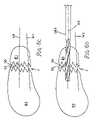
Referring specifically to FIGS.1,2 and3 of the drawings, a compression screw apparatus generally designated10 provided in accordance with the present invention is illustrated. As discussed above,compression screw apparatus 10 can be utilized for compression of any suitable materials, but is particularly suitable for compression of portions or fragments of bone across a fracture line. As shown,compression screw apparatus 10 comprises a primary screw, generally designated PS, and a secondary screw, generally designated SS, adapted to fit onto primary screw PS as further described herein. Primary screw PS and secondary screw SS are illustrated inFIG. 1 in a spaced-apart manner and inFIGS. 2 and 3 with secondary screw SS fitted at least partially onto primary screw PS. In one embodiment, secondary screw SS can be, but certainly does not have to be, at least one-half of the length of primary screw PS to provide a sufficient mating length.
Primary screw PS as shown inFIGS. 1 and 2 is at least generally cylindrical, disposed along a central axis and cannulated as it defines a longitudinal bore orpassage 20 through its middle along its central axis. For smaller applications ofcompression screw 10, primary screw PS could be non-cannulated to provide increased strength. Primary screw PS has aleading end 22 which can be self-tapping for screwing into material such as bone, and a trailing end generally designated24, on the end of primary screw PS opposite leadingend 22. Primary screw PS includes a forward or lead portion designated LP, and a rear or trailing portion designated TP. The outer surface of lead portion LP is at least partially threaded, and preferably is substantially or entirely threaded such as withhelical threads 26 shown best inFIGS. 1 ,2, and3. The outer surface of trailing portion TP is also at least partially threaded, and most preferably is substantially or entirely threaded such as withhelical threads 28, also as best shown inFIGS. 1 ,2, and3.Threads 26 can spiral in the same direction or hand asthreads 28.
The lead ofthreads 26 can be of any suitable lead, such as for example single lead, double lead, or triple lead. Whencompression screw 10 is used for compressing bone,threads 26 are preferably cancellous type and adapted specifically for engaging bone and can include a chamfer and series of notches even at their leading edges to facilitate ease of advancement and self-tapping. Leadingportion LP threads 26 can be self-drilling such that leading portion LP can be driven directly into material such as bone without requiring pre-drilling of a hole therefor. Whencompression screw 10 is used for compressing bone,threads 28 do not need to be adapted for engaging bone sincethreads 28 can preferably be of a smaller major diameter and pitch diameter thanthreads 26 and are specifically designed for receiving secondary screw as described herein.Compression screw apparatus 10 according to this invention could also be configured such that the lead of the various threads could be of other relative amounts, as described below.
Trailingend 24 of trailing portion TP preferably defines a recessedopening 30 configured to be engaged by a suitably configured driver, such as for example driver D1 shown inFIG. 6F , in order to drive and rotate primary screw PS as it is screwed into bone during use as described herein. The end view of trailingend 24 of primary screw PS illustrated inFIG. 4 shows recessed opening30 in a hex configuration which can be engaged by driver D1 in order to appropriately drive and screw into place primary screw PS. The configuration of recessedopening 30 could be of any other suitable configuration and match any correspondingly suitable configuration for the head of driver D1, as known to those of skill in the art of screw and driver apparatuses. For example, the configuration of recessedopening 30 could be of a standard hex as shown, hexalobular (Torx or Torx plus), cruciform or other desired shape with the driving head of driver D1 being of a correspondingly matching shape.
As an optional feature, primary screw PS between leading portion LP and trailing portion TP can include atransition portion 32 where the outer surface of primary screw PS can be smooth and unthreaded. When this feature is included as shown in the drawings,transition portion 32 provides a smooth section ofcompression screw apparatus 10 which can facilitate compression of bone fragments where the bone fragments meet at a compressed fracture line at orproximate transition portion 32. The length of transition portion can extend for any suitable length, and preferably less than approximately 10% or even 5% of the entire length of the primary screw. The diameter oftransition portion 32 can be equal to the major diameter ofthreads 28 of trailing portion TP and smaller than the major diameter ofthreads 26 of leading portion LP as shown best inFIGS. 1 and 2 . It is also envisioned thattransition portion 32 could have any other suitable diameter such as a diameter larger or even smaller than the major diameter ofthreads 26. It is also possible as mentioned above fortransition portion 32 to not be present at all on primary screw PS, in whichcase threads 26 simply are immediately next tothreads 28. The presence of an unthreadedtransition portion 32 is not functionally required and can especially be excluded where the major diameter ofthreads 26 is the same or substantially the same as the diameter of the portion ofthreads 28adjacent threads 26.
Secondary screw SS ofcompression screw apparatus 10 preferably comprises an at least generally cylindrical shaped, sleeve-like screw portion for screwing onto primary screw PS. Secondary screw SS defines a threaded central opening CO along its central axis such that secondary screw SS can be screwed onto trailing portion TP of primary screw PS as helicalinner threads 34 of secondary screw SS can matingly engage and screw ontothreads 28 of trailing portion TP of primary screw PS.
Trailing portion TP of primary screw PS can be straight or slightly tapered, such as at a four(4)-degree or any other suitable angle, so that the diameter of trailing portion TP gradually decreases along the axial length of primary screw PS fromtransition portion 32 to trailingend 24. When trailing portion TP is tapered in this manner, threaded central opening CO of secondary screw SS can also preferably be appropriately tapered so that threaded central opening CO gradually increases in inner diameter toward its end adapted for first advancing onto primary screw PS. This configuration allows secondary screw SS to screw onto primary screw PS with a locking engagement.
The outer surface of secondary screw SS is at least partially threaded, and preferably can be substantially or even entirely threaded such as by outerhelical threads 36 as illustrated inFIGS. 1 ,2 and3.Threads 36 preferably are of a larger major diameter thanthreads 26 of leading portion LP of primary screw PS, but of the same pitch and lead asthreads 26. This preferred relative configuration advantageously ensures that no compression occurs upon insertion of primary screw PS ofcompression screw apparatus 10 and allowsthreads 36 of secondary screw SS to create maximum engagement with bone that has substantially been undisturbed.Threads 36 can spiral in the same direction or hand asthreads threads 36 can be of a constant major diameter on secondary screw SS as shown in the drawings in order to provide the ability to disengage or back outcompression screw apparatus 10 as needed without loss of bone engagement. The initial portion ofthreads 36 which are advanced first onto primary screw PS can, however, slightly taper somewhat similar tothreads 26 of leading portion LP, as shown inFIGS. 1 ,2, and3. Additionally, secondary screw SS can also have a tapered outer diameter such that the diameter of secondary screw SS decreases gradually toward the initial portion ofthreads 36 which are advanced first onto primary screw PS. In this configuration,threads 36 would also have a major diameter that decreases gradually toward the initial portion ofthreads 36 which are advanced first onto primary screw PS.
In order to be able to provide the desired compression as described further hereinbelow,inner threads 34 of secondary screw SS are preferably of a lead that is larger than the lead ofouter threads 36 of secondary screw SS. The lead ofinner threads 34 will in a preferred embodiment therefore also be larger than the lead ofthreads 26 of primary screw sincethreads 26 preferably have a lead that is at least substantially identical to that ofthreads 36 of secondary screw SS. The pitch ofinner threads 34 of secondary screw SS can therefore be smaller than the pitch ofouter threads 36 of secondary screw SS, which can in turn be substantially equivalent to the pitch of leading portion LP.
As can be appreciated by those of skill in the art, relative dimensions and characteristics ofthreads 26 of leading portion LP,threads 28 of trailing portion TP,inner threads 34 of secondary screw SS, andouter threads 36 of secondary screw SS can be as described above and can also suitably vary. For example, the pitch and lead ofthreads 26 can be equal or substantially equal to the pitch and lead ofthreads 36. The pitch ofthreads 28 can also be the same or substantially the same as the pitch ofthreads 34. The pitch ofthreads 28 can be less than the pitch ofthreads 26, and the lead ofthreads 26 can be less than the lead ofthreads 28. With this configuration,compression screw 10 can be inserted by driveably rotating primary screw PS without causing compression of the materials, such as bone fragments, until secondary screw SS is screwed into place after proper positioning of primary screw PS.
It is also envisioned that the configuration and characteristics of thevarious threads threads 36 can be less than the lead ofthreads 26, the lead ofthreads 36 can be less than the lead ofthreads 28, and the lead ofthreads 28 can be larger than the lead ofthreads 36. In this configuration, compression could occur between two pieces of material such as bone even during insertion ofcompression screw 10.
Secondary screw SS can define any suitably configured recess or opening, such as forexample slot 38 in an end thereof which is adapted for engagement by a correspondingly suitably configured driver, such as driver D2 shown inFIG. 6H , which can be a cannulated driver that can slideably fit onto and around driver D1. As can be appreciated by those of skill in the art, primary screw PS can advantageously be rotatably driven or even held in place by driver D1 engaging recessedopening 30 even while driver D2 engagesslot 38 of secondary screw SS to controllably rotate or hold in place secondary screw SS.
Primary screw PS and secondary screw SS can be constructed of any material suitable for compression of bone screw as described herein and as known to those of skill in the art of orthopedic implants. Particularly suitable materials for construction of primary screw PS and secondary screw SS include, for example, surgical implantable material such as titanium or titanium alloys or stainless steel. It is also envisioned that resorbable materials could be utilized.
Referring now toFIGS. 6A-6H of the drawings, exemplary steps are illustrated which are involved in compression of broken or fractured objects utilizingcompression screw apparatus 10. WhileFIGS. 6A-6H illustrate the broken or fractured objects as proximal and distal bone fragments B1 and B2, respectively,compression screw apparatus 10 can be used for compression of any suitable objects even other than bone fragments B1 and B2, such as, for example, wood or metal objects utilized in woodworking or metal working, respectively.
Initially and as illustrated inFIG. 6B , a wire such as guide wire W can be driven through bone fragment B1 across fracture line F and into bone fragment B2 in order to provide appropriate orientation and stability to the fracture line in preparation for installation ofcompression screw 10 as described below. Guide wire W1 can be a Kirschner wire, also known as a K-wire in the field of orthopedic implants. After placement of guide wire W1, guide wire W2 can be driven through bone fragment B1, across fracture line F and into bone fragment B2 at a location wherecompression screw apparatus 10 will be installed.
Drill bit DB1, as shown inFIG. 6D , can then be used to drill through bone fragment B1, across fracture line F, and into bone fragment B2. Drill bit DB1 preferably is cannulated to fit over wire W2 and of a diameter suitable for pre-drilling a hole into which primary screw PS ofcompression screw apparatus 10 can be screwed. A second drill bit DB2, as shown inFIG. 6E , also is preferably cannulated to fit over wire W2 and can be used to drill into bone fragment B1 in order to pre-drill a hole into which secondary screw SS ofcompression screw apparatus 10 can be screwed. Drill bit DB2, as shown inFIG. 6E , is preferably of a larger diameter than drill bit DB1 shown inFIG. 6D . As known to those of skill in the art of orthopedic implants, the cannulation of drill bits DB1 and DB2 when used with guide wire W2 facilitate proper positioning of drill bits DB1 and DB2 during use.
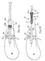
Similar to the placement of drill bits DB1 and DB2 over guide wire W2,compression screw apparatus 10 as shown inFIG. 6F can now be placed and is slideable upon guide wire W2 for proper positioning ofcompression screw apparatus 10 for installation into the predrilled holes. Since the suitably configured recessed opening30 (shown best inFIG. 4 ) of trailing portion TP of primary screw PS can be engaged by a suitable driver of a configuration adapted for rotatably screwing primary screw PS even through central opening CO (best shown inFIG. 5 ) of secondary screw SS,compression screw 10 as shown inFIG. 6F can be placed onto guide wire W2 as a unit with secondary screw SS already screwed at least partially onto trailing portion TP of primary screw PS. As shown inFIG. 6F , cannulated driver D1 is positioned on wire W2 and passes through a portion of central opening CO of secondary screw SS to engage primary screw PS.
As illustrated inFIG. 6G , oncecompression screw apparatus 10 has been placed appropriately upon guide wire W2,compression screw apparatus 10 can be rotatably driven and screwed by driver D1 into the holes predrilled into bone fragments B1 and B2 by drill bit DB1 and DB2. Wire W1 particularly provides stability during this step, and wire W2 continues to facilitate proper positioning and placement ofcompression screw 10. As shown inFIG. 6G , leadingend 22 of leading portion LP of primary screw PS has been screwed into bone fragment B2 the entire extent of the pre-drilled hole to firmly engage bone fragment B2, while secondary screw SS is still sticking partially above the surface of bone fragment B1.Transition portion 32 can preferably be positioned between or proximate fracture line F of bone fragments B1 and B2.
Referring now toFIG. 6H , secondary screw SS is screwed in and tightened by driver D2 for completion of placement ofcompression screw 10. This tightening by driver D1 can occur with driver D2 still engaging primary screw PS to hold it in position as illustrated inFIG. 6H or after driver D1 has already been pulled out from engagement with primary screw PS. Tightening of secondary screw SS causes compression of bone fragments B1 and B2 so that they come together at fracture line F, preferably along or at leastproximate transition portion 32. Secondary screw SS can be tightened so that it is entirely below the surface of bone fragment B1 with no portion sticking above the surface of bone fragment B1. A substantially constant major diameter ofthreads 36 can allow for secondary screw SS to be inserted with no portion or head-like structure sticking out. At this point, wire W2 can be withdrawn. As may be necessary, theentire compression screw 10 can be withdrawn from this position by reversing the steps as described.
It will be understood that various details of the disclosed subject matter may be changed without departing from the scope of the subject matter. Furthermore, the foregoing description is for the purpose of illustration only, and not for the purpose of limitation.
Claims (22)
1. A compression screw apparatus comprising:
a) a primary screw having a leading end and an opposite trailing end, the primary screw having a lead portion configured for screwing into bone and the lead portion having an outer surface that is at least partially threaded and a trailing portion with a continuous outer surface that is at least partially threaded;
b) a secondary screw having an outer surface that is at least partially threaded, the secondary screw defining a central opening with an inner surface that is at least partially threaded, the inner threaded surface being configured for mating engagement on the threaded trailing portion of the primary screw such that rotation of the secondary screw relative to the primary screw causes the translation of the secondary screw relative to the primary screw along the threaded trailing portion of the primary screw;
c.) wherein the threads of the lead portion of the primary screw and the threads of the outer surface of the secondary screw are of at least substantially identical lead; and
d.) wherein the threads of the trailing portion of the primary screw taper at least partially with a gradually decreasing diameter toward the trailing end of the primary screw.
2. A compression screw apparatus comprising:
c) a primary screw having a leading end and an opposite trailing end, the primary screw having a lead portion configured for screwing into bone and the lead portion having an outer surface that is at least partially threaded and a trailing portion with a continuous outer surface that is at least partially threaded;
d) a secondary screw having an outer surface that is at least partially threaded, the secondary screw defining a central opening with an inner surface that is at least partially threaded, the inner threaded surface being configured for mating engagement on the threaded trailing portion of the primary screw such that rotation of the secondary screw relative to the primary screw causes the translation of the secondary screw relative to the primary screw along the threaded trailing portion of the primary screw;
c.) wherein the threads of the lead portion of the primary screw and the threads of the outer surface of the secondary screw are of at least substantially identical lead; and
d.) wherein the trailing portion has a diameter that gradually decreases toward the trailing end.
3. The compression screw apparatus ofclaim 2 wherein the central opening of the secondary screw is of a diameter that increases toward an end of the secondary screw adapted for advancing first onto the trailing portion of the primary screw.
4. A compression screw apparatus comprising:
a) a cannulated, at least generally cylindrical primary screw having a lead portion terminating in a leading end and a trailing portion terminating in a trailing end, the lead portion having an outer surface that is at least partially threaded and the trailing portion having a continuous outer surface that is at least partially threaded, the trailing portion of the primary screw having a diameter that decreases toward the trailing end; and
b) an at least generally cylindrical secondary screw having an outer surface that is at least partially threaded with outer threads, the secondary screw defining a central opening with an inner surface that is at least partially threaded with inner threads, the central opening having an inner diameter that increases axially along a length of the secondary screw for mating engagement on the threaded trailing portion of the primary screw such that rotation of the secondary screw relative to the primary screw causes the translation of the secondary screw relative to the primary screw along the threaded trailing portion of the primary screw, wherein the inner threads of the secondary screw are of a larger lead than the outer threads of the secondary screw.
5. The compression screw apparatus ofclaim 4 wherein the threads of the lead portion of the primary screw and the threads of the outer surface of the secondary screw are of at least substantially identical lead.
6. A compression screw apparatus comprising:
a) a primary screw having a leading end and an opposite trailing end, the primary screw having a lead portion with an outer surface that is at least partially threaded and a trailing portion with a continuous outer surface that is at least partially threaded;
b) a secondary screw having an outer surface that is at least partially threaded, the secondary screw defining a central opening with an inner surface that is at least partially threaded, the inner threaded surface being configured for mating engagement on the threaded trailing portion of the primary screw;
c) wherein the threads of the lead portion of the primary screw and the threads of the outer surface of the secondary screw are of at least substantially identical lead; and
d) wherein the threads of the trailing portion of the primary screw taper at least partially with a gradually decreasing diameter toward the trailing end of the primary screw.
7. The compression screw apparatus ofclaim 6 wherein the primary screw is cannulated.
8. The compression screw apparatus ofclaim 6 wherein the outer surface of the primary screw has a smooth, unthreaded transition portion between the lead portion and the trailing portion of the primary screw.
9. The compression screw apparatus ofclaim 8 wherein the transition portion extends for less than approximately 5% of an entire length of the primary screw.
10. The compression screw apparatus ofclaim 6 wherein the threads of the leading portion of the primary screw are of a greater pitch than the threads of the trailing portion.
11. The compression screw apparatus ofclaim 6 wherein the threads of the leading portion of the primary screw have a deeper root than the threads of the trailing portion.
12. The compression screw apparatus ofclaim 6 wherein the threads of the leading portion of the primary screw taper with a gradually increasing diameter starting at or proximate the leading end of the primary screw.
13. The compression screw apparatus ofclaim 6 wherein the trailing end of the primary screw defines a recessed opening.
14. The compression screw apparatus ofclaim 6 wherein the threads of the leading portion of the primary screw have a greater major diameter than that of the threads outer surface of the secondary screw.
15. The compression screw apparatus ofclaim 6 wherein the outer threads of the secondary screw are larger in diameter than the threads of the leading portion of the primary screw.
16. The compression screw apparatus ofclaim 6 wherein the outer threads of the secondary screw are of at least substantially identical pitch as the threads of the leading portion of the primary screw.
17. The compression screw apparatus ofclaim 6 wherein the outer threads of the secondary screw are of an at least substantially constant major diameter.
18. The compression screw apparatus ofclaim 6 wherein the threads of the inner surface of the secondary screw are of a larger lead than the threads of the outer surface of the secondary screw.
19. The compression screw apparatus ofclaim 6 wherein the threads of the primary screw and the threads of the secondary screw are of the same hand.
20. The compression screw apparatus ofclaim 6 wherein an end of the central opening is adapted for receiving a driver.
21. A compression screw apparatus comprising:
a) a primary screw having a leading end and an opposite trailing end, the primary screw having a lead portion with an outer surface that is at least partially threaded and a trailing portion with a continuous outer surface that is at least partially threaded;
b) a secondary screw having an outer surface that is at least partially threaded, the secondary screw defining a central opening with an inner surface that is at least partially threaded, the inner threaded surface being configured for mating engagement on the threaded trailing portion of the primary screw;
c) wherein the threads of the lead portion of the primary screw and the threads of the outer surface of the secondary screw are of at least substantially identical lead; and
d) wherein the trailing portion has a diameter that gradually decreases toward the trailing end.
22. The compression screw apparatus ofclaim 21 wherein the central opening of the secondary screw is of a diameter that increases toward an end of the secondary screw adapted for advancing first onto the trailing portion of the primary screw.
Priority Applications (1)
| Application Number | Priority Date | Filing Date | Title |
|---|---|---|---|
| US10/768,875US7582107B2 (en) | 2003-02-03 | 2004-01-30 | Compression screw apparatuses, systems and methods |
Applications Claiming Priority (2)
| Application Number | Priority Date | Filing Date | Title |
|---|---|---|---|
| US44456503P | 2003-02-03 | 2003-02-03 | |
| US10/768,875US7582107B2 (en) | 2003-02-03 | 2004-01-30 | Compression screw apparatuses, systems and methods |
Publications (2)
| Publication Number | Publication Date |
|---|---|
| US20040210227A1 US20040210227A1 (en) | 2004-10-21 |
| US7582107B2true US7582107B2 (en) | 2009-09-01 |
Family
ID=32850889
Family Applications (1)
| Application Number | Title | Priority Date | Filing Date |
|---|---|---|---|
| US10/768,875Expired - Fee RelatedUS7582107B2 (en) | 2003-02-03 | 2004-01-30 | Compression screw apparatuses, systems and methods |
Country Status (3)
| Country | Link |
|---|---|
| US (1) | US7582107B2 (en) |
| EP (1) | EP1594411A4 (en) |
| WO (1) | WO2004069031A2 (en) |
Cited By (102)
| Publication number | Priority date | Publication date | Assignee | Title |
|---|---|---|---|---|
| US20050267478A1 (en)* | 2003-06-13 | 2005-12-01 | Corradi Ralph R | Surgical fastener with predetermined resorption rate |
| US20060095040A1 (en)* | 2004-02-23 | 2006-05-04 | Andre Schlienger | Bone screw |
| US20070038220A1 (en)* | 2004-04-27 | 2007-02-15 | Shipp John I | Absorbable Fastener for Hernia Mesh Fixation |
| US20070213732A1 (en)* | 2006-03-13 | 2007-09-13 | The Johns Hopkins University | Orthopedic Screw System |
| US20080039846A1 (en)* | 2006-08-10 | 2008-02-14 | Shih-Tseng Lee | Expansion screw set and hollow nail and interior nail thereof |
| US20090118771A1 (en)* | 2007-04-11 | 2009-05-07 | Eduardo Gonzalez-Hernandez | Curved assembly for reattachment of fragmented bone segments |
| US20100087820A1 (en)* | 2006-09-28 | 2010-04-08 | Orthofix S.R.L. | Intramedullary osteosynthesis device |
| US20100211118A1 (en)* | 2009-02-16 | 2010-08-19 | Stryker Trauma Ag | Bone screw and method of manufacturing same |
| US20100281677A1 (en)* | 2007-07-27 | 2010-11-11 | Ludwig Hettich & Co. | Production Of A Planned Distribution Of Internal Stress In Components By The Insertion Of Screws Or Threaded Rods Having A Thread Pitch That Is Variable In The Longitudinal Direction |
| US20110152948A1 (en)* | 2009-06-19 | 2011-06-23 | David Crook | Triple lead bone screw |
| US20110224738A1 (en)* | 2005-05-10 | 2011-09-15 | Acumed Llc | Bone connector with pivotable joint |
| US20110230884A1 (en)* | 2008-06-24 | 2011-09-22 | Adam Mantzaris | Hybrid intramedullary fixation assembly and method of use |
| US8088163B1 (en) | 2008-02-06 | 2012-01-03 | Kleiner Jeffrey B | Tools and methods for spinal fusion |
| USD656610S1 (en) | 2009-02-06 | 2012-03-27 | Kleiner Jeffrey B | Spinal distraction instrument |
| US8182485B1 (en) | 2003-11-21 | 2012-05-22 | Toby Orthopaedics, Llc | Fracture fixation system |
| US20120197254A1 (en)* | 2008-06-24 | 2012-08-02 | Scott Wolfe | Intramedullary Fixation Assembly and Method of Use |
| US8303589B2 (en) | 2008-06-24 | 2012-11-06 | Extremity Medical Llc | Fixation system, an intramedullary fixation assembly and method of use |
| US8328806B2 (en) | 2008-06-24 | 2012-12-11 | Extremity Medical, Llc | Fixation system, an intramedullary fixation assembly and method of use |
| US8343199B2 (en) | 2008-06-24 | 2013-01-01 | Extremity Medical, Llc | Intramedullary fixation screw, a fixation system, and method of fixation of the subtalar joint |
| US8366748B2 (en) | 2008-12-05 | 2013-02-05 | Kleiner Jeffrey | Apparatus and method of spinal implant and fusion |
| US8388660B1 (en) | 2006-08-01 | 2013-03-05 | Samy Abdou | Devices and methods for superior fixation of orthopedic devices onto the vertebral column |
| US8469999B2 (en) | 2008-04-17 | 2013-06-25 | Eduardo Gonzalez-Hernandez | Soft tissue attachment system and clip |
| US8523918B2 (en) | 2002-12-03 | 2013-09-03 | Baxano Surgical, Inc. | Therapy to adjacent motion segments |
| US20130238036A1 (en)* | 2010-11-30 | 2013-09-12 | Genossis Llc | Bone Compression and Fixation Devices |
| US8685031B2 (en) | 2009-09-18 | 2014-04-01 | Spinal Surgical Strategies, Llc | Bone graft delivery system |
| US8764808B2 (en) | 2008-03-10 | 2014-07-01 | Eduardo Gonzalez-Hernandez | Bone fixation system |
| US20140257408A1 (en)* | 2013-03-07 | 2014-09-11 | Warsaw Orthopedic, Inc. | Surgical implant system and method |
| US8864654B2 (en) | 2010-04-20 | 2014-10-21 | Jeffrey B. Kleiner | Method and apparatus for performing retro peritoneal dissection |
| US8870963B2 (en) | 2010-10-27 | 2014-10-28 | Toby Orthopaedics, Inc. | System and method for fracture replacement of comminuted bone fractures or portions thereof adjacent bone joints |
| US20140343616A1 (en)* | 2013-04-22 | 2014-11-20 | Daniel Sellers | Arthrodesis compression device |
| US8906028B2 (en) | 2009-09-18 | 2014-12-09 | Spinal Surgical Strategies, Llc | Bone graft delivery device and method of using the same |
| US8911479B2 (en) | 2012-01-10 | 2014-12-16 | Roger P. Jackson | Multi-start closures for open implants |
| US8920476B2 (en) | 2008-06-24 | 2014-12-30 | Extremity Medical, Llc | Fixation system, an intramedullary fixation assembly and method of use |
| US8956356B2 (en) | 2011-05-17 | 2015-02-17 | DePuy Synthes Products, LLC | Telescoping screw for femoral neck fractures |
| US8961573B2 (en) | 2010-10-05 | 2015-02-24 | Toby Orthopaedics, Inc. | System and method for facilitating repair and reattachment of comminuted bone portions |
| USD723682S1 (en) | 2013-05-03 | 2015-03-03 | Spinal Surgical Strategies, Llc | Bone graft delivery tool |
| US20150105829A1 (en)* | 2012-05-22 | 2015-04-16 | Austofix Group Limited | Bone fixation device |
| US9011505B2 (en) | 2009-02-09 | 2015-04-21 | Memometal Technologies | Screw for osteosynthesis and arthrodesis |
| US9017329B2 (en) | 2008-06-24 | 2015-04-28 | Extremity Medical, Llc | Intramedullary fixation assembly and method of use |
| US9044282B2 (en) | 2008-06-24 | 2015-06-02 | Extremity Medical Llc | Intraosseous intramedullary fixation assembly and method of use |
| US9060877B2 (en) | 2009-09-18 | 2015-06-23 | Spinal Surgical Strategies, Llc | Fusion cage with combined biological delivery system |
| WO2015100149A1 (en)* | 2013-12-26 | 2015-07-02 | Skeletal Dynamics, Llc | Headless compression screw |
| US9161794B2 (en) | 2011-04-14 | 2015-10-20 | Globus Medical, Inc. | Expanding spinal anchor |
| US9173694B2 (en) | 2009-09-18 | 2015-11-03 | Spinal Surgical Strategies, Llc | Fusion cage with combined biological delivery system |
| US9186193B2 (en) | 2009-09-18 | 2015-11-17 | Spinal Surgical Strategies, Llc | Fusion cage with combined biological delivery system |
| US9247943B1 (en) | 2009-02-06 | 2016-02-02 | Kleiner Intellectual Property, Llc | Devices and methods for preparing an intervertebral workspace |
| US20160030097A1 (en)* | 2013-03-15 | 2016-02-04 | Zimmer Gmbh | Surgical locking screw |
| US9254154B2 (en) | 2011-03-03 | 2016-02-09 | Toby Orthopaedic, Inc. | Anterior lesser tuberosity fixed angle fixation device and method of use associated therewith |
| USD750249S1 (en) | 2014-10-20 | 2016-02-23 | Spinal Surgical Strategies, Llc | Expandable fusion cage |
| US9271772B2 (en) | 2011-10-27 | 2016-03-01 | Toby Orthopaedics, Inc. | System and method for fracture replacement of comminuted bone fractures or portions thereof adjacent bone joints |
| US9283008B2 (en) | 2012-12-17 | 2016-03-15 | Toby Orthopaedics, Inc. | Bone plate for plate osteosynthesis and method for use thereof |
| US9333014B2 (en) | 2013-03-15 | 2016-05-10 | Eduardo Gonzalez-Hernandez | Bone fixation and reduction apparatus and method for fixation and reduction of a distal bone fracture and malunion |
| US20160166292A1 (en)* | 2013-12-12 | 2016-06-16 | Mark Allen Mighell | Intramedullary anchor-screw fracture fixation |
| US9402667B2 (en) | 2011-11-09 | 2016-08-02 | Eduardo Gonzalez-Hernandez | Apparatus and method for use of the apparatus for fracture fixation of the distal humerus |
| US9629729B2 (en) | 2009-09-18 | 2017-04-25 | Spinal Surgical Strategies, Llc | Biological delivery system with adaptable fusion cage interface |
| US20170151061A1 (en)* | 2015-09-10 | 2017-06-01 | Vilex In Tennessee, Inc. | Arthrodesis Implant and System Therefor |
| US20170164954A1 (en)* | 2015-12-11 | 2017-06-15 | IntraFuse, LLC | Flexible tap |
| US9717403B2 (en) | 2008-12-05 | 2017-08-01 | Jeffrey B. Kleiner | Method and apparatus for performing retro peritoneal dissection |
| US9730797B2 (en) | 2011-10-27 | 2017-08-15 | Toby Orthopaedics, Inc. | Bone joint replacement and repair assembly and method of repairing and replacing a bone joint |
| USD797290S1 (en) | 2015-10-19 | 2017-09-12 | Spinal Surgical Strategies, Llc | Bone graft delivery tool |
| US20170296245A1 (en)* | 2016-04-19 | 2017-10-19 | Globus Medical, Inc. | Implantable compression screws |
| US9827028B2 (en)* | 2010-02-26 | 2017-11-28 | Biedermann Technologies Gmbh & Co. Kg | Bone screw |
| US9855036B2 (en) | 2013-11-13 | 2018-01-02 | Arthrex, Inc. | Staples for generating and applying compression within a body |
| US9861413B2 (en) | 2013-11-11 | 2018-01-09 | Arthrex, Inc. | Screws for generating and applying compression within a body |
| US10016198B2 (en) | 2014-11-13 | 2018-07-10 | Arthrex, Inc. | Staples for generating and applying compression within a body |
| US10166055B2 (en) | 2014-05-16 | 2019-01-01 | Biomet C.V. | Method and apparatus for bone fixation |
| US10245159B1 (en) | 2009-09-18 | 2019-04-02 | Spinal Surgical Strategies, Llc | Bone graft delivery system and method for using same |
| WO2019104127A1 (en)* | 2017-11-21 | 2019-05-31 | Esp Medical Solutions, Llc | Hybrid radiolucent screw with radiopaque components and radiolucent components and method of manufacture |
| USD853560S1 (en) | 2008-10-09 | 2019-07-09 | Nuvasive, Inc. | Spinal implant insertion device |
| US10357260B2 (en) | 2015-11-02 | 2019-07-23 | First Ray, LLC | Orthopedic fastener, retainer, and guide methods |
| US10376367B2 (en) | 2015-07-02 | 2019-08-13 | First Ray, LLC | Orthopedic fasteners, instruments and methods |
| US10478238B2 (en) | 2014-12-02 | 2019-11-19 | Activortho, Inc. | Active compression devices, methods of assembly and methods of use |
| US10543107B2 (en) | 2009-12-07 | 2020-01-28 | Samy Abdou | Devices and methods for minimally invasive spinal stabilization and instrumentation |
| US10548740B1 (en) | 2016-10-25 | 2020-02-04 | Samy Abdou | Devices and methods for vertebral bone realignment |
| US10575961B1 (en) | 2011-09-23 | 2020-03-03 | Samy Abdou | Spinal fixation devices and methods of use |
| US10667923B2 (en) | 2016-10-31 | 2020-06-02 | Warsaw Orthopedic, Inc. | Sacro-iliac joint implant system and method |
| US10695105B2 (en) | 2012-08-28 | 2020-06-30 | Samy Abdou | Spinal fixation devices and methods of use |
| US10806497B2 (en) | 2014-11-17 | 2020-10-20 | Bridging Medical, Llc | Bone compression systems |
| US10857003B1 (en) | 2015-10-14 | 2020-12-08 | Samy Abdou | Devices and methods for vertebral stabilization |
| US10898249B2 (en) | 2015-01-28 | 2021-01-26 | Arthrex, Inc. | Self-compressing screws for generating and applying compression within a body |
| US10918498B2 (en) | 2004-11-24 | 2021-02-16 | Samy Abdou | Devices and methods for inter-vertebral orthopedic device placement |
| US10939944B2 (en)* | 2018-04-18 | 2021-03-09 | Glw, Inc. | Removable orthopedic screws |
| US10973656B2 (en) | 2009-09-18 | 2021-04-13 | Spinal Surgical Strategies, Inc. | Bone graft delivery system and method for using same |
| US10973648B1 (en) | 2016-10-25 | 2021-04-13 | Samy Abdou | Devices and methods for vertebral bone realignment |
| US11006982B2 (en) | 2012-02-22 | 2021-05-18 | Samy Abdou | Spinous process fixation devices and methods of use |
| US11076901B2 (en) | 2017-04-21 | 2021-08-03 | DePuy Synthes Products, Inc. | Angled flutes in cannulated bone screws |
| US11173040B2 (en) | 2012-10-22 | 2021-11-16 | Cogent Spine, LLC | Devices and methods for spinal stabilization and instrumentation |
| US11179248B2 (en) | 2018-10-02 | 2021-11-23 | Samy Abdou | Devices and methods for spinal implantation |
| US11224467B2 (en) | 2016-02-26 | 2022-01-18 | Activortho, Inc. | Active compression apparatus, methods of assembly and methods of use |
| US11234746B2 (en) | 2016-02-26 | 2022-02-01 | Activortho, Inc. | Active compression apparatus, methods of assembly and methods of use |
| US11344354B2 (en) | 2019-09-09 | 2022-05-31 | Warsaw Orthopedic, Inc. | Surgical instrument and method |
| US11490884B2 (en)* | 2015-12-16 | 2022-11-08 | Conmed Corporation | Knotless suture anchor and deployment device |
| US11553948B2 (en) | 2021-05-20 | 2023-01-17 | University Of Utah Research Foundation | Bone fixation devices, systems, and methods |
| US11564812B2 (en) | 2019-09-09 | 2023-01-31 | Warsaw Orthopedic, Inc. | Surgical instrument and method |
| US11666455B2 (en) | 2009-09-18 | 2023-06-06 | Spinal Surgical Strategies, Inc., A Nevada Corporation | Bone graft delivery devices, systems and kits |
| US20230285156A1 (en)* | 2022-03-11 | 2023-09-14 | University Of Maryland, Baltimore | Device and method for sacroiliac fusion |
| US20230363808A1 (en)* | 2022-05-12 | 2023-11-16 | Glw, Inc. | Orthopedic Screw with Radiolucent and Radiopaque Thread Portions |
| US20230397937A1 (en)* | 2015-10-05 | 2023-12-14 | Arthrex, Inc. | Surgical screw system |
| US11844557B2 (en) | 2020-05-12 | 2023-12-19 | Globus Medical, Inc. | Locking variable length compression screw |
| US11998255B1 (en) | 2023-08-26 | 2024-06-04 | University Of Utah Research Foundation | Cannulated continuous compression screw |
| US12256968B2 (en) | 2020-11-11 | 2025-03-25 | Acumed Llc | Variable pitch tapered compressing screw for dynamic compression |
| US12279972B2 (en) | 2008-05-22 | 2025-04-22 | Spinal Surgical Strategies, Inc. | Spinal fusion cage system with inserter |
Families Citing this family (118)
| Publication number | Priority date | Publication date | Assignee | Title |
|---|---|---|---|---|
| FR2897259B1 (en) | 2006-02-15 | 2008-05-09 | Ldr Medical Soc Par Actions Si | INTERSOMATIC TRANSFORAMINAL CAGE WITH INTERBREBAL FUSION GRAFT AND CAGE IMPLANTATION INSTRUMENT |
| US7776068B2 (en)* | 2003-10-23 | 2010-08-17 | Trans1 Inc. | Spinal motion preservation assemblies |
| US7601171B2 (en)* | 2003-10-23 | 2009-10-13 | Trans1 Inc. | Spinal motion preservation assemblies |
| US7938836B2 (en)* | 2003-10-23 | 2011-05-10 | Trans1, Inc. | Driver assembly for simultaneous axial delivery of spinal implants |
| US7717958B2 (en) | 2000-02-16 | 2010-05-18 | Trans1, Inc. | Prosthetic nucleus apparatus |
| US7833250B2 (en) | 2004-11-10 | 2010-11-16 | Jackson Roger P | Polyaxial bone screw with helically wound capture connection |
| US7235079B2 (en) | 2004-11-18 | 2007-06-26 | Acumed Llc | Composite bone fasteners |
| US8216243B2 (en)* | 2001-12-04 | 2012-07-10 | Synthes Usa, Llc | Headless compression screw with integrated reduction-compression instrument |
| US7955388B2 (en)* | 2006-11-01 | 2011-06-07 | Acumed Llc | Orthopedic connector system |
| US8876868B2 (en) | 2002-09-06 | 2014-11-04 | Roger P. Jackson | Helical guide and advancement flange with radially loaded lip |
| AU2003901971A0 (en)* | 2003-04-23 | 2003-05-15 | Dugal Simon Stewart James | A fixation device and method of fixation |
| US7377923B2 (en) | 2003-05-22 | 2008-05-27 | Alphatec Spine, Inc. | Variable angle spinal screw assembly |
| US7967850B2 (en) | 2003-06-18 | 2011-06-28 | Jackson Roger P | Polyaxial bone anchor with helical capture connection, insert and dual locking assembly |
| US8926670B2 (en) | 2003-06-18 | 2015-01-06 | Roger P. Jackson | Polyaxial bone screw assembly |
| US8366753B2 (en) | 2003-06-18 | 2013-02-05 | Jackson Roger P | Polyaxial bone screw assembly with fixed retaining structure |
| US7766915B2 (en) | 2004-02-27 | 2010-08-03 | Jackson Roger P | Dynamic fixation assemblies with inner core and outer coil-like member |
| US7776067B2 (en) | 2005-05-27 | 2010-08-17 | Jackson Roger P | Polyaxial bone screw with shank articulation pressure insert and method |
| DE10350424B4 (en)* | 2003-10-29 | 2006-03-30 | Ulrich Gmbh & Co. Kg | bone screw |
| US7789896B2 (en)* | 2005-02-22 | 2010-09-07 | Jackson Roger P | Polyaxial bone screw assembly |
| JP2008508980A (en)* | 2004-08-09 | 2008-03-27 | トランス1,インク. | Nucleus nucleus prosthesis device and method |
| US8926672B2 (en) | 2004-11-10 | 2015-01-06 | Roger P. Jackson | Splay control closure for open bone anchor |
| US8444681B2 (en) | 2009-06-15 | 2013-05-21 | Roger P. Jackson | Polyaxial bone anchor with pop-on shank, friction fit retainer and winged insert |
| US9168069B2 (en) | 2009-06-15 | 2015-10-27 | Roger P. Jackson | Polyaxial bone anchor with pop-on shank and winged insert with lower skirt for engaging a friction fit retainer |
| US8740955B2 (en)* | 2005-02-15 | 2014-06-03 | Zimmer, Inc. | Bone screw with multiple thread profiles for far cortical locking and flexible engagement to a bone |
| US7371260B2 (en)* | 2005-10-26 | 2008-05-13 | Biomet Sports Medicine, Inc. | Method and instrumentation for the preparation and transplantation of osteochondral allografts |
| US8002841B2 (en)* | 2006-01-20 | 2011-08-23 | Synthes Usa, Llc | Method of preparing an ankle joint for replacement, joint prosthesis, and cutting alignment apparatus for use in performing an arthroplasty procedure |
| US8075604B2 (en) | 2006-02-16 | 2011-12-13 | Warsaw Orthopedic, Inc. | Multi-thread bone screw and method |
| US8147531B2 (en)* | 2006-03-17 | 2012-04-03 | Tornier, Inc. | Compression pin with opposed threaded regions |
| CA2663912A1 (en)* | 2006-08-14 | 2008-02-21 | Smith & Nephew, Inc. | Fracture fixation device |
| US20080177333A1 (en)* | 2006-10-24 | 2008-07-24 | Warsaw Orthopedic, Inc. | Adjustable jacking implant |
| US20100145462A1 (en)* | 2006-10-24 | 2010-06-10 | Trans1 Inc. | Preformed membranes for use in intervertebral disc spaces |
| US8088147B2 (en)* | 2006-10-24 | 2012-01-03 | Trans1 Inc. | Multi-membrane prosthetic nucleus |
| WO2008064037A2 (en)* | 2006-11-17 | 2008-05-29 | Synthes (U.S.A.) | Intramedullary nail including stable locking bolts |
| DE102006056950B4 (en)* | 2006-11-30 | 2013-07-25 | Normed Medizin-Technik Gmbh | Orthopedic lag screw for osteosynthesis and / or fixation of bone segments |
| US8128671B2 (en)* | 2007-04-04 | 2012-03-06 | Warsaw Orthopedic, Inc. | Variable flank bone screw |
| ITRE20070053A1 (en)* | 2007-04-12 | 2008-10-13 | Cgm Spa | "BONE SURGICAL INSTRUMENT" |
| ITRE20070054A1 (en)* | 2007-04-12 | 2008-10-13 | Cgm Spa | "BONE SURGICAL INSTRUMENT" |
| US8979904B2 (en) | 2007-05-01 | 2015-03-17 | Roger P Jackson | Connecting member with tensioned cord, low profile rigid sleeve and spacer with torsion control |
| FR2916624B1 (en) | 2007-05-29 | 2009-08-21 | Small Bone Innovations Interna | BONE SCREW, IN PARTICULAR OSTEOSYNTHESIS |
| US7604640B2 (en)* | 2007-06-14 | 2009-10-20 | Zimmer Spine Austin, Inc. | Device and system for applying rotary impact |
| KR100950990B1 (en)* | 2007-09-14 | 2010-04-02 | 최길운 | Bone Therapy |
| US8322256B2 (en)* | 2007-10-05 | 2012-12-04 | Biomet Manufacturing Corp. | System for forming a tendon-bone graft |
| US8303592B2 (en)* | 2007-10-05 | 2012-11-06 | Biomet Manufacturing Corp. | System for forming a tendon-bone graft |
| US20090198289A1 (en)* | 2008-02-02 | 2009-08-06 | Manderson Easton L | Fortified cannulated screw |
| US9072561B2 (en)* | 2008-03-25 | 2015-07-07 | The Center For Orthopedic Research And Education, Inc. | Spinal facet fixation device |
| AU2010260521C1 (en) | 2008-08-01 | 2013-08-01 | Roger P. Jackson | Longitudinal connecting member with sleeved tensioned cords |
| WO2010017168A2 (en)* | 2008-08-05 | 2010-02-11 | University Of Toledo | Pedicle screw assembly having a retractable screw tip for facilitating the securement of the pedicle screw assembly to a spinal vertebra |
| US8403973B2 (en)* | 2008-08-05 | 2013-03-26 | The University Of Toledo | Pedicle screw assembly having a retractable screw tip for facilitating the securement of the pedicle screw assembly to a spinal vertebra |
| US9907597B2 (en)* | 2008-08-12 | 2018-03-06 | Charles E. Kollmer | Bone compression system and associated methods |
| AT507271B1 (en)* | 2008-08-20 | 2010-07-15 | Univ Wien Med | KNOCHENSCHRAUBENSET |
| US20110276095A1 (en)* | 2008-12-09 | 2011-11-10 | Yossef Bar | Double Threaded Orthopedic Screw |
| US8771315B2 (en) | 2008-12-15 | 2014-07-08 | Smith & Nephew, Inc. | Composite anchor |
| US8864773B2 (en) | 2009-01-14 | 2014-10-21 | Globus Medical, Inc. | Devices and methods for treating vertebral fractures |
| US9089377B2 (en) | 2009-02-23 | 2015-07-28 | Orthopediatrics Corp. | Bone screw |
| ES2355345B1 (en)* | 2009-05-25 | 2012-02-15 | Rotor Componentes Tecnologicos, S.L. | SCREW AND NUT ASSEMBLY WITH DOUBLE THREADS. |
| US11229457B2 (en) | 2009-06-15 | 2022-01-25 | Roger P. Jackson | Pivotal bone anchor assembly with insert tool deployment |
| CN103826560A (en) | 2009-06-15 | 2014-05-28 | 罗杰.P.杰克逊 | Polyaxial Bone Anchor with Socket Stem and Winged Inserts with Friction Fit Compression Collars |
| US8998959B2 (en) | 2009-06-15 | 2015-04-07 | Roger P Jackson | Polyaxial bone anchors with pop-on shank, fully constrained friction fit retainer and lock and release insert |
| US8747472B2 (en)* | 2009-08-14 | 2014-06-10 | Baxano Surgical, Inc. | Spinal therapy device with fixated distraction distance |
| ES2535939T3 (en)* | 2009-12-03 | 2015-05-19 | Biedermann Technologies Gmbh & Co. Kg | Bone screw |
| EP2329780B1 (en)* | 2009-12-03 | 2013-02-20 | Biedermann Technologies GmbH & Co. KG | Bone screw |
| USD696103S1 (en) | 2010-04-07 | 2013-12-24 | Fastex Industry Co., Ltd. | Screw |
| US20110251651A1 (en)* | 2010-04-07 | 2011-10-13 | Sung-Po Cho | Screw |
| US20130338722A1 (en)* | 2010-07-07 | 2013-12-19 | Matthew Adam Yalizis | Compression bone screw |
| JP5989759B2 (en)* | 2011-03-22 | 2016-09-07 | スミス アンド ネフュー インコーポレーテッド | Mooring system and feeding device for use with the mooring system |
| SE535749C2 (en)* | 2011-05-09 | 2012-12-04 | Akoustos Ab | Fixing arrangement with two sub-parts for holding together two constructions and tools for the arrangement |
| TR201104622A1 (en)* | 2011-05-11 | 2012-11-21 | Yilmaz Olday | Double compression screw and application method. |
| US20140155943A1 (en)* | 2011-07-01 | 2014-06-05 | Elos Medtech Pinol A/S | Bone implant |
| US9155580B2 (en)* | 2011-08-25 | 2015-10-13 | Medos International Sarl | Multi-threaded cannulated bone anchors |
| US9636230B2 (en)* | 2011-08-25 | 2017-05-02 | Vikram Talwar | Interbody fusion implant and screw guide |
| WO2013052807A2 (en) | 2011-10-05 | 2013-04-11 | H. Lee Moffitt Cancer Center And Research Institute, Inc. | Bone fusion system |
| US10799367B2 (en) | 2011-10-05 | 2020-10-13 | H. Lee Moffitt Cancer Center And Research Institute, Inc. | Bone fusion system |
| US20130158608A1 (en)* | 2011-12-20 | 2013-06-20 | Osteomed L.P. | Plate and cannulated transfixation screw system for human implant |
| TWI469763B (en)* | 2012-06-26 | 2015-01-21 | Sheng Hui Meng | Bone implant |
| US9480515B2 (en) | 2012-07-12 | 2016-11-01 | Exsomed International IP, LLC | Metacarpal bone stabilization device |
| US9060821B2 (en)* | 2012-11-16 | 2015-06-23 | DePuy Synthes Products, Inc. | Locking and lagging bone screws |
| US8911478B2 (en) | 2012-11-21 | 2014-12-16 | Roger P. Jackson | Splay control closure for open bone anchor |
| US10058354B2 (en) | 2013-01-28 | 2018-08-28 | Roger P. Jackson | Pivotal bone anchor assembly with frictional shank head seating surfaces |
| US8852239B2 (en) | 2013-02-15 | 2014-10-07 | Roger P Jackson | Sagittal angle screw with integral shank and receiver |
| CN105188562B (en) | 2013-03-06 | 2019-02-26 | 史密夫和内修有限公司 | Micro Anchor |
| US20140277190A1 (en)* | 2013-03-14 | 2014-09-18 | Howmedica Osteonics Corp. | Compression screw with variable pitch thread |
| FR3005569B1 (en) | 2013-05-16 | 2021-09-03 | Ldr Medical | VERTEBRAL IMPLANT, VERTEBRAL IMPLANT FIXATION DEVICE AND IMPLANTATION INSTRUMENTATION |
| WO2015050900A1 (en)* | 2013-10-02 | 2015-04-09 | Exsomed Holding Company Llc | Scaphoid screws and fasteners |
| WO2015050895A1 (en) | 2013-10-02 | 2015-04-09 | Exsomed Holding Company Llc | Full wrist fusion device |
| US9566092B2 (en) | 2013-10-29 | 2017-02-14 | Roger P. Jackson | Cervical bone anchor with collet retainer and outer locking sleeve |
| US9717533B2 (en) | 2013-12-12 | 2017-08-01 | Roger P. Jackson | Bone anchor closure pivot-splay control flange form guide and advancement structure |
| WO2015095353A1 (en) | 2013-12-17 | 2015-06-25 | H. Lee Moffit Cancer Center And Research Institute, Inc. | Transdiscal screw |
| US9451993B2 (en) | 2014-01-09 | 2016-09-27 | Roger P. Jackson | Bi-radial pop-on cervical bone anchor |
| FR3016793B1 (en) | 2014-01-30 | 2021-05-07 | Ldr Medical | ANCHORING DEVICE FOR SPINAL IMPLANT, SPINAL IMPLANT AND IMPLANTATION INSTRUMENTATION |
| CN106102613B (en)* | 2014-02-06 | 2019-07-19 | 英格奈特概念有限公司 | Bone screw assembly |
| FR3020756B1 (en) | 2014-05-06 | 2022-03-11 | Ldr Medical | VERTEBRAL IMPLANT, VERTEBRAL IMPLANT FIXATION DEVICE AND IMPLANT INSTRUMENTATION |
| US9597119B2 (en) | 2014-06-04 | 2017-03-21 | Roger P. Jackson | Polyaxial bone anchor with polymer sleeve |
| US10064658B2 (en) | 2014-06-04 | 2018-09-04 | Roger P. Jackson | Polyaxial bone anchor with insert guides |
| US10322009B2 (en) | 2014-08-01 | 2019-06-18 | H. Lee Moffitt Cancer Center And Research Institute, Inc. | Expandable intervertebral cage |
| CN105683593A (en)* | 2014-10-06 | 2016-06-15 | 瑞特医疗技术公司 | Torque drivers for headless threaded compression fasteners |
| US10932838B2 (en)* | 2015-04-03 | 2021-03-02 | Life Spine, Inc. | Bone compression screws |
| WO2016186847A1 (en) | 2015-05-19 | 2016-11-24 | Exsomed International IP, LLC | Distal radius plate |
| EP3123970B1 (en)* | 2015-07-31 | 2018-04-18 | Lechoslaw Franciszek Ciupik | Stabilization of two adjacent bones |
| CN105078526B (en)* | 2015-09-21 | 2017-06-23 | 中南大学湘雅医院 | Device for repairing ligament or tendon defect |
| CN105342678A (en)* | 2015-12-15 | 2016-02-24 | 徐强 | Secondary screw and bone screw adopting same |
| US10245091B2 (en) | 2015-12-30 | 2019-04-02 | Exsomed Holding Company, Llc | Dip fusion spike screw |
| US11147604B2 (en) | 2016-01-12 | 2021-10-19 | ExsoMed Corporation | Bone stabilization device |
| US11278335B2 (en) | 2016-04-19 | 2022-03-22 | Globus Medical, Inc. | Implantable compression screws |
| US10463414B2 (en)* | 2016-05-02 | 2019-11-05 | Shukla Medical | Orthopedic screw extractor |
| US10194923B2 (en) | 2016-05-10 | 2019-02-05 | Exsomed International IP, LLC | Tool for percutaneous joint cartilage destruction and preparation for joint fusion |
| EP4278998B1 (en) | 2016-07-29 | 2025-05-21 | Zimmer Biomet Spine, Inc. | Bone anchor housing limiter |
| AU2018243875B2 (en)* | 2017-03-30 | 2022-05-26 | K2M, Inc. | Bone anchor apparatus and method of use thereof |
| US11147681B2 (en) | 2017-09-05 | 2021-10-19 | ExsoMed Corporation | Small bone angled compression screw |
| US11191645B2 (en)* | 2017-09-05 | 2021-12-07 | ExsoMed Corporation | Small bone tapered compression screw |
| JP2020532407A (en) | 2017-09-05 | 2020-11-12 | エクソームド コーポレーションExsomed Corporation | Threaded intramedullary nail for radial cortex fixation |
| US11000325B2 (en)* | 2018-02-27 | 2021-05-11 | Acumed Llc | Bone fastener with partially overlapping threads and a varying lead |
| US11877934B2 (en)* | 2020-04-07 | 2024-01-23 | Globus Medical, Inc. | Pedicle-based intradiscal fixation devices and methods |
| EP4014905A1 (en)* | 2020-12-17 | 2022-06-22 | LfC Spólka z o.o. | Stabilization of two adjacent bones |
| US20220249131A1 (en)* | 2021-02-09 | 2022-08-11 | Rtg Scientific, Llc | Fastening devices, systems, and methods |
| EP4346658A4 (en)* | 2021-05-28 | 2025-04-23 | Acumed LLC | Bone fixation systems and nail having compressive threading |
| US12137941B2 (en) | 2021-12-23 | 2024-11-12 | Orthofix S.R.L. | Orthopedic cable bone transport device and bone transport system comprising said device |
| CN114209409A (en)* | 2021-12-31 | 2022-03-22 | 航天中心医院 | Detachable screw and internal fixing device for fixing front ring of pelvic fracture |
| WO2024133885A1 (en)* | 2022-12-23 | 2024-06-27 | Orthofix S.R.L. | Orthopedic cable bone transport device and bone transport system comprising said device |
Citations (40)
| Publication number | Priority date | Publication date | Assignee | Title |
|---|---|---|---|---|
| US1576413A (en)* | 1925-05-13 | 1926-03-09 | Cubitt Archibald Stannard | Locking screw and the like |
| US3051169A (en)* | 1957-12-07 | 1962-08-28 | Stille Werner Ab | Surgical screw connector |
| US4175555A (en) | 1977-02-24 | 1979-11-27 | Interfix Limited | Bone screw |
| US4432358A (en)* | 1982-01-22 | 1984-02-21 | Fixel Irving E | Compression hip screw apparatus |
| US4456005A (en)* | 1982-09-30 | 1984-06-26 | Lichty Terry K | External compression bone fixation device |
| US4640271A (en) | 1985-11-07 | 1987-02-03 | Zimmer, Inc. | Bone screw |
| US4772286A (en) | 1987-02-17 | 1988-09-20 | E. Marlowe Goble | Ligament attachment method and apparatus |
| US4858601A (en) | 1988-05-27 | 1989-08-22 | Glisson Richard R | Adjustable compression bone screw |
| USRE33348E (en) | 1985-11-07 | 1990-09-25 | Zimmer, Inc. | Bone screw |
| US5019079A (en) | 1989-11-20 | 1991-05-28 | Zimmer, Inc. | Bone screw |
| US5100405A (en)* | 1990-09-07 | 1992-03-31 | Mclaren Alexander C | Locking cap for medical implants |
| US5167664A (en)* | 1991-08-26 | 1992-12-01 | Zimmer, Inc. | Ratcheting bone screw |
| US5201733A (en) | 1992-01-21 | 1993-04-13 | Etheredge Iii James L | Method and apparatus for internal fixation of fractures |
| US5217462A (en) | 1991-03-05 | 1993-06-08 | Pfizer Hospital Products Group, Inc. | Screw and driver |
| US5437674A (en) | 1992-08-25 | 1995-08-01 | Alexandre Worcel | Osteosynthesis device |
| US5498265A (en) | 1991-03-05 | 1996-03-12 | Howmedica Inc. | Screw and driver |
| US5522817A (en) | 1989-03-31 | 1996-06-04 | United States Surgical Corporation | Absorbable surgical fastener with bone penetrating elements |
| US5562672A (en) | 1993-01-21 | 1996-10-08 | Acumed, Inc. | Tapered bone screw with continuously varying pitch |
| US5584629A (en)* | 1995-05-30 | 1996-12-17 | Crystal Medical Technology, A Division Of Folsom Metal Products, Inc. | Connector for medical implant |
| US5725529A (en)* | 1990-09-25 | 1998-03-10 | Innovasive Devices, Inc. | Bone fastener |
| US5743912A (en)* | 1995-08-23 | 1998-04-28 | Biomat | Upper femoral epiphysis osteosynthesis implant |
| US5824087A (en) | 1994-04-11 | 1998-10-20 | Aberdeen University And Plasma Biotal Limited | Bone regeneration |
| US5827285A (en)* | 1996-12-12 | 1998-10-27 | Bramlet; Dale G. | Multipiece interfragmentary fixation assembly |
| US5871486A (en)* | 1993-01-21 | 1999-02-16 | Acumed, Inc. | Variable pitch bone screw |
| US5964768A (en) | 1993-01-21 | 1999-10-12 | Acumed, Inc. | Tapered bone screw with continuously varying pitch |
| US5964767A (en)* | 1997-09-12 | 1999-10-12 | Tapia; Eduardo Armando | Hollow sealable device for temporary or permanent surgical placement through a bone to provide a passageway into a cavity or internal anatomic site in a mammal |
| US5976139A (en)* | 1996-07-17 | 1999-11-02 | Bramlet; Dale G. | Surgical fastener assembly |
| US5993450A (en) | 1995-06-07 | 1999-11-30 | Worcel; Alexandre | Osteosynthesis ring usable in combination with a pin or a screw, and compressing device therefore |
| US5997541A (en) | 1996-01-18 | 1999-12-07 | Synthes (U.S.A) | Threaded washer |
| US6030162A (en) | 1998-12-18 | 2000-02-29 | Acumed, Inc. | Axial tension screw |
| US6048343A (en)* | 1999-06-02 | 2000-04-11 | Mathis; John M. | Bone screw system |
| US6139552A (en) | 1998-05-13 | 2000-10-31 | K. K. Hollyx | Bone jointer and a bone jointer fixing tool |
| US6187008B1 (en) | 1999-07-07 | 2001-02-13 | Bristol-Myers Squibb | Device for temporarily fixing bones |
| US6299615B1 (en) | 1993-01-21 | 2001-10-09 | Acumed, Inc. | System for fusing joints |
| US6306140B1 (en) | 2001-01-17 | 2001-10-23 | Synthes (Usa) | Bone screw |
| US6319254B1 (en)* | 1999-04-22 | 2001-11-20 | Newdeal | Compression osteosynthesis screw, and an ancillaty device for use therewith |
| US20010049528A1 (en)* | 1999-05-12 | 2001-12-06 | Kohei Kubota | Implant screw |
| US6413260B1 (en)* | 1999-08-17 | 2002-07-02 | Pioneer Laboratories, Inc. | Bone connector system |
| US6458134B1 (en)* | 1999-08-17 | 2002-10-01 | Pioneer Laboratories, Inc. | Bone connector system with anti-rotational feature |
| US6668688B2 (en)* | 2001-06-28 | 2003-12-30 | Mayo Foundation | Expandable screw apparatus and method thereof |
Family Cites Families (3)
| Publication number | Priority date | Publication date | Assignee | Title |
|---|---|---|---|---|
| WO1991009572A1 (en)* | 1989-12-21 | 1991-07-11 | Bakinsky Nauchno-Issledovatelsky Institut Travmatologii I Ortopedii | Compressing screw for osteosynthesis |
| FR2699065B1 (en)* | 1992-12-10 | 1995-03-10 | Hardy Jean Marie | Self-compressing screw for the treatment of epiphyseal and / or osteochondral fractures. |
| FR2745709B1 (en)* | 1996-03-08 | 1998-08-14 | Caffiniere Jean Yves De | COMPRESSION RECOVERY SCREW FOR PERCUTANEOUS OSTEOSYNTHESIS |
- 2004
- 2004-01-30USUS10/768,875patent/US7582107B2/ennot_activeExpired - Fee Related
- 2004-01-30WOPCT/US2004/002573patent/WO2004069031A2/enactiveApplication Filing
- 2004-01-30EPEP04706936Apatent/EP1594411A4/ennot_activeWithdrawn
Patent Citations (42)
| Publication number | Priority date | Publication date | Assignee | Title |
|---|---|---|---|---|
| US1576413A (en)* | 1925-05-13 | 1926-03-09 | Cubitt Archibald Stannard | Locking screw and the like |
| US3051169A (en)* | 1957-12-07 | 1962-08-28 | Stille Werner Ab | Surgical screw connector |
| US4175555A (en) | 1977-02-24 | 1979-11-27 | Interfix Limited | Bone screw |
| US4432358A (en)* | 1982-01-22 | 1984-02-21 | Fixel Irving E | Compression hip screw apparatus |
| US4456005A (en)* | 1982-09-30 | 1984-06-26 | Lichty Terry K | External compression bone fixation device |
| US4640271A (en) | 1985-11-07 | 1987-02-03 | Zimmer, Inc. | Bone screw |
| USRE33348E (en) | 1985-11-07 | 1990-09-25 | Zimmer, Inc. | Bone screw |
| US4772286A (en) | 1987-02-17 | 1988-09-20 | E. Marlowe Goble | Ligament attachment method and apparatus |
| US4858601A (en) | 1988-05-27 | 1989-08-22 | Glisson Richard R | Adjustable compression bone screw |
| US5522817A (en) | 1989-03-31 | 1996-06-04 | United States Surgical Corporation | Absorbable surgical fastener with bone penetrating elements |
| US5019079A (en) | 1989-11-20 | 1991-05-28 | Zimmer, Inc. | Bone screw |
| US5100405A (en)* | 1990-09-07 | 1992-03-31 | Mclaren Alexander C | Locking cap for medical implants |
| US5725529A (en)* | 1990-09-25 | 1998-03-10 | Innovasive Devices, Inc. | Bone fastener |
| US5217462A (en) | 1991-03-05 | 1993-06-08 | Pfizer Hospital Products Group, Inc. | Screw and driver |
| US5498265A (en) | 1991-03-05 | 1996-03-12 | Howmedica Inc. | Screw and driver |
| US5167664A (en)* | 1991-08-26 | 1992-12-01 | Zimmer, Inc. | Ratcheting bone screw |
| US5201733A (en) | 1992-01-21 | 1993-04-13 | Etheredge Iii James L | Method and apparatus for internal fixation of fractures |
| US5437674A (en) | 1992-08-25 | 1995-08-01 | Alexandre Worcel | Osteosynthesis device |
| US5562672A (en) | 1993-01-21 | 1996-10-08 | Acumed, Inc. | Tapered bone screw with continuously varying pitch |
| US6299615B1 (en) | 1993-01-21 | 2001-10-09 | Acumed, Inc. | System for fusing joints |
| US5871486A (en)* | 1993-01-21 | 1999-02-16 | Acumed, Inc. | Variable pitch bone screw |
| US5964768A (en) | 1993-01-21 | 1999-10-12 | Acumed, Inc. | Tapered bone screw with continuously varying pitch |
| US5824087A (en) | 1994-04-11 | 1998-10-20 | Aberdeen University And Plasma Biotal Limited | Bone regeneration |
| US5584629A (en)* | 1995-05-30 | 1996-12-17 | Crystal Medical Technology, A Division Of Folsom Metal Products, Inc. | Connector for medical implant |
| US5993450A (en) | 1995-06-07 | 1999-11-30 | Worcel; Alexandre | Osteosynthesis ring usable in combination with a pin or a screw, and compressing device therefore |
| US5743912A (en)* | 1995-08-23 | 1998-04-28 | Biomat | Upper femoral epiphysis osteosynthesis implant |
| US5997541A (en) | 1996-01-18 | 1999-12-07 | Synthes (U.S.A) | Threaded washer |
| US6048344A (en) | 1996-01-18 | 2000-04-11 | Synthes (U.S.A.) | Threaded washer and bone screw apparatus |
| US5976139A (en)* | 1996-07-17 | 1999-11-02 | Bramlet; Dale G. | Surgical fastener assembly |
| US5827285A (en)* | 1996-12-12 | 1998-10-27 | Bramlet; Dale G. | Multipiece interfragmentary fixation assembly |
| US5964767A (en)* | 1997-09-12 | 1999-10-12 | Tapia; Eduardo Armando | Hollow sealable device for temporary or permanent surgical placement through a bone to provide a passageway into a cavity or internal anatomic site in a mammal |
| US6139552A (en) | 1998-05-13 | 2000-10-31 | K. K. Hollyx | Bone jointer and a bone jointer fixing tool |
| US6224606B1 (en) | 1998-05-13 | 2001-05-01 | K. K. Hollyx | Bone jointer and a bone jointer fixing tool |
| US6030162A (en) | 1998-12-18 | 2000-02-29 | Acumed, Inc. | Axial tension screw |
| US6319254B1 (en)* | 1999-04-22 | 2001-11-20 | Newdeal | Compression osteosynthesis screw, and an ancillaty device for use therewith |
| US20010049528A1 (en)* | 1999-05-12 | 2001-12-06 | Kohei Kubota | Implant screw |
| US6048343A (en)* | 1999-06-02 | 2000-04-11 | Mathis; John M. | Bone screw system |
| US6187008B1 (en) | 1999-07-07 | 2001-02-13 | Bristol-Myers Squibb | Device for temporarily fixing bones |
| US6413260B1 (en)* | 1999-08-17 | 2002-07-02 | Pioneer Laboratories, Inc. | Bone connector system |
| US6458134B1 (en)* | 1999-08-17 | 2002-10-01 | Pioneer Laboratories, Inc. | Bone connector system with anti-rotational feature |
| US6306140B1 (en) | 2001-01-17 | 2001-10-23 | Synthes (Usa) | Bone screw |
| US6668688B2 (en)* | 2001-06-28 | 2003-12-30 | Mayo Foundation | Expandable screw apparatus and method thereof |
Non-Patent Citations (4)
| Title |
|---|
| International Preliminary Examing Authority for PCT/US04/002573 dated May 9, 2005. |
| Martin et al., "Central Tarsal Bone Factures in Six Horses: Report on the use of a Cannulated Compression Bone Screw," Equine Practice, vol. 14, No. 10, p. 23-27, (Nov./Dec. 1992). |
| Notification of Transmittal of the International Search Report for International Application No. PCT/US04/02573 dated Dec. 17, 2004. |
| Sukul et al., "Biomechanical Measurements on Scaphoid Bone Screws in an Experimental Model," J. Biomechanics, vol. 23, No. 11, p. 1115-1121, (1990). |
Cited By (207)
| Publication number | Priority date | Publication date | Assignee | Title |
|---|---|---|---|---|
| US8523918B2 (en) | 2002-12-03 | 2013-09-03 | Baxano Surgical, Inc. | Therapy to adjacent motion segments |
| US10070860B2 (en) | 2003-06-13 | 2018-09-11 | Covidien Lp | Multiple member interconnect for surgical instrument and absorbable screw fastener |
| US9662106B2 (en) | 2003-06-13 | 2017-05-30 | Covidien Lp | Surgical fastener with predetermined resorption rate |
| US9364274B2 (en) | 2003-06-13 | 2016-06-14 | Covidien Lp | Multiple member interconnect for surgical instrument and absorbable screw fastener |
| US8002811B2 (en)* | 2003-06-13 | 2011-08-23 | Tyco Healthcare Group Lp | Surgical fastener with predetermined resorption rate |
| US8821557B2 (en) | 2003-06-13 | 2014-09-02 | Covidien Lp | Surgical fastener with predetermined resorption rate |
| US20050267478A1 (en)* | 2003-06-13 | 2005-12-01 | Corradi Ralph R | Surgical fastener with predetermined resorption rate |
| US8414627B2 (en) | 2003-06-13 | 2013-04-09 | Covidien Lp | Surgical fastener with predetermined resorption rate |
| US9788833B2 (en) | 2003-06-13 | 2017-10-17 | Covidien Lp | Multiple member interconnect for surgical instrument and absorbable screw fastener |
| US8292933B2 (en) | 2003-06-13 | 2012-10-23 | Tyco Healthcare Group Lp | Multiple member interconnect for surgical instrument and absorbable screw fastener |
| US9259221B2 (en) | 2003-06-13 | 2016-02-16 | Covidien Lp | Multiple member interconnect for surgical instrument and absorbable screw fastener |
| US20100191294A1 (en)* | 2003-06-13 | 2010-07-29 | Tyco Healthcare Group Lp | Multiple member interconnect for surgical instrument and absorbable screw fastener |
| US9186138B2 (en) | 2003-06-13 | 2015-11-17 | Covidien Lp | Surgical fastener with predetermined resorption rate |
| US8361075B2 (en) | 2003-11-21 | 2013-01-29 | Toby Orthopaedics, Inc. | Method for repairing fractured bone |
| US8182485B1 (en) | 2003-11-21 | 2012-05-22 | Toby Orthopaedics, Llc | Fracture fixation system |
| US8574234B2 (en) | 2003-11-21 | 2013-11-05 | Toby Orthopaedics, Inc. | Fracture fixation system |
| US8162998B2 (en)* | 2004-02-23 | 2012-04-24 | Synthes Usa, Llc | Bone screw |
| US20060095040A1 (en)* | 2004-02-23 | 2006-05-04 | Andre Schlienger | Bone screw |
| US10478179B2 (en)* | 2004-04-27 | 2019-11-19 | Covidien Lp | Absorbable fastener for hernia mesh fixation |
| US20110087240A1 (en)* | 2004-04-27 | 2011-04-14 | Tyco Healthcare Group Lp | Absorbable fastener for hernia mesh fixation |
| US20070038220A1 (en)* | 2004-04-27 | 2007-02-15 | Shipp John I | Absorbable Fastener for Hernia Mesh Fixation |
| US9332983B2 (en) | 2004-04-27 | 2016-05-10 | Covidien Lp | Absorbable fastener for hernia mesh fixation |
| US11096799B2 (en) | 2004-11-24 | 2021-08-24 | Samy Abdou | Devices and methods for inter-vertebral orthopedic device placement |
| US10918498B2 (en) | 2004-11-24 | 2021-02-16 | Samy Abdou | Devices and methods for inter-vertebral orthopedic device placement |
| US11992423B2 (en) | 2004-11-24 | 2024-05-28 | Samy Abdou | Devices and methods for inter-vertebral orthopedic device placement |
| US20110224738A1 (en)* | 2005-05-10 | 2011-09-15 | Acumed Llc | Bone connector with pivotable joint |
| US8617227B2 (en)* | 2005-05-10 | 2013-12-31 | Acumed Llc | Bone connector with pivotable joint |
| US8343200B2 (en)* | 2006-03-13 | 2013-01-01 | The Johns Hopkins University | Orthopedic screw system |
| US20070213732A1 (en)* | 2006-03-13 | 2007-09-13 | The Johns Hopkins University | Orthopedic Screw System |
| US8388660B1 (en) | 2006-08-01 | 2013-03-05 | Samy Abdou | Devices and methods for superior fixation of orthopedic devices onto the vertebral column |
| US20080039846A1 (en)* | 2006-08-10 | 2008-02-14 | Shih-Tseng Lee | Expansion screw set and hollow nail and interior nail thereof |
| US20100042164A1 (en)* | 2006-08-10 | 2010-02-18 | Shih-Tseng Lee | Expansion screw set and hollow nail and interior nail thereof |
| US20100087820A1 (en)* | 2006-09-28 | 2010-04-08 | Orthofix S.R.L. | Intramedullary osteosynthesis device |
| US20090118771A1 (en)* | 2007-04-11 | 2009-05-07 | Eduardo Gonzalez-Hernandez | Curved assembly for reattachment of fragmented bone segments |
| US8343197B2 (en)* | 2007-04-11 | 2013-01-01 | Toby Orthopaedics, Inc. | Curved assembly for reattachment of fragmented bone segments |
| US9151314B2 (en)* | 2007-07-27 | 2015-10-06 | Ludwig Hettich & Co. | Production of a planned distribution of internal stress in components by the insertion of screws or threaded rods having a thread pitch that is variable in the longitudinal direction |
| US20100281677A1 (en)* | 2007-07-27 | 2010-11-11 | Ludwig Hettich & Co. | Production Of A Planned Distribution Of Internal Stress In Components By The Insertion Of Screws Or Threaded Rods Having A Thread Pitch That Is Variable In The Longitudinal Direction |
| US10179054B2 (en) | 2008-02-06 | 2019-01-15 | Jeffrey B. Kleiner | Spinal fusion cage system with inserter |
| US9439782B2 (en) | 2008-02-06 | 2016-09-13 | Jeffrey B. Kleiner | Spinal fusion cage system with inserter |
| USD696399S1 (en) | 2008-02-06 | 2013-12-24 | Kleiner Intellectual Property, Llc | Spinal distraction instrument |
| US8292960B2 (en) | 2008-02-06 | 2012-10-23 | Kleiner Intellectual Property, Llc | Spinal fusion cage with removable planar elements |
| USD700322S1 (en) | 2008-02-06 | 2014-02-25 | Jeffrey B. Kleiner | Intervertebral surgical tool |
| US8088163B1 (en) | 2008-02-06 | 2012-01-03 | Kleiner Jeffrey B | Tools and methods for spinal fusion |
| US8277510B2 (en) | 2008-02-06 | 2012-10-02 | Kleiner Intellectual Property, Llc | Tools and methods for spinal fusion |
| US11129730B2 (en) | 2008-02-06 | 2021-09-28 | Spinal Surgical Strategies, Inc., a Nevada corpora | Spinal fusion cage system with inserter |
| US8715355B2 (en) | 2008-02-06 | 2014-05-06 | Nuvasive, Inc. | Spinal fusion cage with removable planar elements |
| US8808305B2 (en) | 2008-02-06 | 2014-08-19 | Jeffrey B. Kleiner | Spinal fusion cage system with inserter |
| US8764808B2 (en) | 2008-03-10 | 2014-07-01 | Eduardo Gonzalez-Hernandez | Bone fixation system |
| US8690916B2 (en) | 2008-04-17 | 2014-04-08 | Eduardo Gonzalez-Hernandez | Soft tissue attachment system and clip |
| US8469999B2 (en) | 2008-04-17 | 2013-06-25 | Eduardo Gonzalez-Hernandez | Soft tissue attachment system and clip |
| US12279972B2 (en) | 2008-05-22 | 2025-04-22 | Spinal Surgical Strategies, Inc. | Spinal fusion cage system with inserter |
| US10751097B2 (en) | 2008-06-24 | 2020-08-25 | Extremity Medical Llc | Intraosseous intramedullary fixation assembly and method of use |
| US8920476B2 (en) | 2008-06-24 | 2014-12-30 | Extremity Medical, Llc | Fixation system, an intramedullary fixation assembly and method of use |
| US8303589B2 (en) | 2008-06-24 | 2012-11-06 | Extremity Medical Llc | Fixation system, an intramedullary fixation assembly and method of use |
| US8900274B2 (en) | 2008-06-24 | 2014-12-02 | Extremity Medical Llc | Fixation system, an intramedullary fixation assembly and method of use |
| US8328806B2 (en) | 2008-06-24 | 2012-12-11 | Extremity Medical, Llc | Fixation system, an intramedullary fixation assembly and method of use |
| US11974786B2 (en) | 2008-06-24 | 2024-05-07 | Extremity Medical L.L.C. | Intraosseous intramedullary fixation assembly and method of use |
| US8920453B2 (en) | 2008-06-24 | 2014-12-30 | Extremity Medical, Llc | Fixation system, an intramedullary fixation assembly and method of use |
| US9289220B2 (en)* | 2008-06-24 | 2016-03-22 | Extremity Medical Llc | Intramedullary fixation assembly and method of use |
| US20120197254A1 (en)* | 2008-06-24 | 2012-08-02 | Scott Wolfe | Intramedullary Fixation Assembly and Method of Use |
| US8343199B2 (en) | 2008-06-24 | 2013-01-01 | Extremity Medical, Llc | Intramedullary fixation screw, a fixation system, and method of fixation of the subtalar joint |
| US9044282B2 (en) | 2008-06-24 | 2015-06-02 | Extremity Medical Llc | Intraosseous intramedullary fixation assembly and method of use |
| US11298166B2 (en) | 2008-06-24 | 2022-04-12 | Extremity Medical Llc | Intraosseous intramedullary fixation assembly and method of use |
| US20110230884A1 (en)* | 2008-06-24 | 2011-09-22 | Adam Mantzaris | Hybrid intramedullary fixation assembly and method of use |
| US9017329B2 (en) | 2008-06-24 | 2015-04-28 | Extremity Medical, Llc | Intramedullary fixation assembly and method of use |
| USD853560S1 (en) | 2008-10-09 | 2019-07-09 | Nuvasive, Inc. | Spinal implant insertion device |
| US8870882B2 (en) | 2008-12-05 | 2014-10-28 | Jeffrey KLEINER | Apparatus and method of spinal implant and fusion |
| US9427264B2 (en) | 2008-12-05 | 2016-08-30 | Jeffrey KLEINER | Apparatus and method of spinal implant and fusion |
| US9717403B2 (en) | 2008-12-05 | 2017-08-01 | Jeffrey B. Kleiner | Method and apparatus for performing retro peritoneal dissection |
| US8366748B2 (en) | 2008-12-05 | 2013-02-05 | Kleiner Jeffrey | Apparatus and method of spinal implant and fusion |
| US9861496B2 (en) | 2008-12-05 | 2018-01-09 | Jeffrey B. Kleiner | Apparatus and method of spinal implant and fusion |
| US10617293B2 (en) | 2008-12-05 | 2020-04-14 | Jeffrey B. Kleiner | Method and apparatus for performing retro peritoneal dissection |
| USD656610S1 (en) | 2009-02-06 | 2012-03-27 | Kleiner Jeffrey B | Spinal distraction instrument |
| US9247943B1 (en) | 2009-02-06 | 2016-02-02 | Kleiner Intellectual Property, Llc | Devices and methods for preparing an intervertebral workspace |
| US10201355B2 (en) | 2009-02-06 | 2019-02-12 | Kleiner Intellectual Property, Llc | Angled surgical tool for removing tissue from within an intervertebral space |
| US9826988B2 (en) | 2009-02-06 | 2017-11-28 | Kleiner Intellectual Property, Llc | Devices and methods for preparing an intervertebral workspace |
| USD667542S1 (en) | 2009-02-06 | 2012-09-18 | Kleiner Jeffrey B | Spinal distraction instrument |
| US9011505B2 (en) | 2009-02-09 | 2015-04-21 | Memometal Technologies | Screw for osteosynthesis and arthrodesis |
| US9504504B2 (en) | 2009-02-09 | 2016-11-29 | Stryker European Holdings I, Llc | Screw for osteosynthesis and arthrodesis |
| US20100211118A1 (en)* | 2009-02-16 | 2010-08-19 | Stryker Trauma Ag | Bone screw and method of manufacturing same |
| US20110152948A1 (en)* | 2009-06-19 | 2011-06-23 | David Crook | Triple lead bone screw |
| US8382811B2 (en) | 2009-06-19 | 2013-02-26 | U.S. Spine, Inc. | Triple lead bone screw |
| US10195053B2 (en) | 2009-09-18 | 2019-02-05 | Spinal Surgical Strategies, Llc | Bone graft delivery system and method for using same |
| US11660208B2 (en) | 2009-09-18 | 2023-05-30 | Spinal Surgical Strategies, Inc. | Bone graft delivery system and method for using same |
| US12167971B2 (en) | 2009-09-18 | 2024-12-17 | Spinal Surgical Strategies, Inc. | Bone graft delivery devices, systems and kits |
| US8709088B2 (en) | 2009-09-18 | 2014-04-29 | Spinal Surgical Strategies, Llc | Fusion cage with combined biological delivery system |
| US8685031B2 (en) | 2009-09-18 | 2014-04-01 | Spinal Surgical Strategies, Llc | Bone graft delivery system |
| US10973656B2 (en) | 2009-09-18 | 2021-04-13 | Spinal Surgical Strategies, Inc. | Bone graft delivery system and method for using same |
| US9173694B2 (en) | 2009-09-18 | 2015-11-03 | Spinal Surgical Strategies, Llc | Fusion cage with combined biological delivery system |
| US12053393B2 (en) | 2009-09-18 | 2024-08-06 | Spinal Surgical Strategies, Inc. | Bone graft delivery system and method for use |
| US11666455B2 (en) | 2009-09-18 | 2023-06-06 | Spinal Surgical Strategies, Inc., A Nevada Corporation | Bone graft delivery devices, systems and kits |
| US9629729B2 (en) | 2009-09-18 | 2017-04-25 | Spinal Surgical Strategies, Llc | Biological delivery system with adaptable fusion cage interface |
| US8906028B2 (en) | 2009-09-18 | 2014-12-09 | Spinal Surgical Strategies, Llc | Bone graft delivery device and method of using the same |
| US10245159B1 (en) | 2009-09-18 | 2019-04-02 | Spinal Surgical Strategies, Llc | Bone graft delivery system and method for using same |
| US9060877B2 (en) | 2009-09-18 | 2015-06-23 | Spinal Surgical Strategies, Llc | Fusion cage with combined biological delivery system |
| US9186193B2 (en) | 2009-09-18 | 2015-11-17 | Spinal Surgical Strategies, Llc | Fusion cage with combined biological delivery system |
| US10945861B2 (en) | 2009-12-07 | 2021-03-16 | Samy Abdou | Devices and methods for minimally invasive spinal stabilization and instrumentation |
| US10543107B2 (en) | 2009-12-07 | 2020-01-28 | Samy Abdou | Devices and methods for minimally invasive spinal stabilization and instrumentation |
| US10610380B2 (en) | 2009-12-07 | 2020-04-07 | Samy Abdou | Devices and methods for minimally invasive spinal stabilization and instrumentation |
| US10857004B2 (en) | 2009-12-07 | 2020-12-08 | Samy Abdou | Devices and methods for minimally invasive spinal stabilization and instrumentation |
| US11918486B2 (en) | 2009-12-07 | 2024-03-05 | Samy Abdou | Devices and methods for minimally invasive spinal stabilization and instrumentation |
| US9827028B2 (en)* | 2010-02-26 | 2017-11-28 | Biedermann Technologies Gmbh & Co. Kg | Bone screw |
| US8864654B2 (en) | 2010-04-20 | 2014-10-21 | Jeffrey B. Kleiner | Method and apparatus for performing retro peritoneal dissection |
| US9271776B2 (en) | 2010-10-05 | 2016-03-01 | Toby Orthopaedics, Inc. | System and method for facilitating repair and reattachment of comminuted bone portions |
| US8961573B2 (en) | 2010-10-05 | 2015-02-24 | Toby Orthopaedics, Inc. | System and method for facilitating repair and reattachment of comminuted bone portions |
| US11266506B2 (en) | 2010-10-27 | 2022-03-08 | Toby Orthopaedics, Inc. | System for fracture replacement of comminuted bone fractures or portions thereof adjacent bone joints |
| US9757240B2 (en) | 2010-10-27 | 2017-09-12 | Toby Orthopaedics, Inc. | System and method for fracture replacement of comminuted bone fractures or portions thereof adjacent bone joints |
| US8870963B2 (en) | 2010-10-27 | 2014-10-28 | Toby Orthopaedics, Inc. | System and method for fracture replacement of comminuted bone fractures or portions thereof adjacent bone joints |
| US10524919B2 (en) | 2010-10-27 | 2020-01-07 | Toby Orthopaedics, Inc. | System and method for fracture replacement of comminuted bone fractures or portions thereof adjacent bone joints |
| US20130238036A1 (en)* | 2010-11-30 | 2013-09-12 | Genossis Llc | Bone Compression and Fixation Devices |
| US10258380B2 (en) | 2010-11-30 | 2019-04-16 | Genossis Llc | Bone compression and fixation devices |
| US9795412B2 (en)* | 2010-11-30 | 2017-10-24 | Genossis Llc | Bone compression and fixation devices |
| US9254154B2 (en) | 2011-03-03 | 2016-02-09 | Toby Orthopaedic, Inc. | Anterior lesser tuberosity fixed angle fixation device and method of use associated therewith |
| US10736683B2 (en)* | 2011-04-14 | 2020-08-11 | Globus Medical, Inc. | Expanding spinal anchor |
| US9161794B2 (en) | 2011-04-14 | 2015-10-20 | Globus Medical, Inc. | Expanding spinal anchor |
| US10064669B2 (en) | 2011-04-14 | 2018-09-04 | Globus Medical, Inc. | Expanding spinal anchor |
| US8956356B2 (en) | 2011-05-17 | 2015-02-17 | DePuy Synthes Products, LLC | Telescoping screw for femoral neck fractures |
| US11517449B2 (en) | 2011-09-23 | 2022-12-06 | Samy Abdou | Spinal fixation devices and methods of use |
| US11324608B2 (en) | 2011-09-23 | 2022-05-10 | Samy Abdou | Spinal fixation devices and methods of use |
| US12167973B2 (en) | 2011-09-23 | 2024-12-17 | Samy Abdou | Spinal fixation devices and methods of use |
| US10575961B1 (en) | 2011-09-23 | 2020-03-03 | Samy Abdou | Spinal fixation devices and methods of use |
| US10188522B2 (en) | 2011-10-27 | 2019-01-29 | Toby Orthopaedics, Inc. | System for replacement of at least a portion of a carpal articular surface of a radius |
| US9271772B2 (en) | 2011-10-27 | 2016-03-01 | Toby Orthopaedics, Inc. | System and method for fracture replacement of comminuted bone fractures or portions thereof adjacent bone joints |
| US11285020B2 (en) | 2011-10-27 | 2022-03-29 | Toby Orthopaedics, Inc. | Bone joint replacement and repair assembly and method of repairing and replacing a bone joint |
| US9730797B2 (en) | 2011-10-27 | 2017-08-15 | Toby Orthopaedics, Inc. | Bone joint replacement and repair assembly and method of repairing and replacing a bone joint |
| US10299939B2 (en) | 2011-10-27 | 2019-05-28 | Toby Orthopaedics, Inc. | Bone joint replacement and repair assembly and method of repairing and replacing a bone joint |
| US11129723B2 (en) | 2011-10-27 | 2021-09-28 | Toby Orthopaedics, Inc | System and method for fracture replacement of comminuted bone fractures or portions thereof adjacent bone joints |
| US9402667B2 (en) | 2011-11-09 | 2016-08-02 | Eduardo Gonzalez-Hernandez | Apparatus and method for use of the apparatus for fracture fixation of the distal humerus |
| US8911479B2 (en) | 2012-01-10 | 2014-12-16 | Roger P. Jackson | Multi-start closures for open implants |
| US11839413B2 (en) | 2012-02-22 | 2023-12-12 | Samy Abdou | Spinous process fixation devices and methods of use |
| US11006982B2 (en) | 2012-02-22 | 2021-05-18 | Samy Abdou | Spinous process fixation devices and methods of use |
| US20150105829A1 (en)* | 2012-05-22 | 2015-04-16 | Austofix Group Limited | Bone fixation device |
| US11559336B2 (en) | 2012-08-28 | 2023-01-24 | Samy Abdou | Spinal fixation devices and methods of use |
| US10695105B2 (en) | 2012-08-28 | 2020-06-30 | Samy Abdou | Spinal fixation devices and methods of use |
| US11173040B2 (en) | 2012-10-22 | 2021-11-16 | Cogent Spine, LLC | Devices and methods for spinal stabilization and instrumentation |
| US11918483B2 (en) | 2012-10-22 | 2024-03-05 | Cogent Spine Llc | Devices and methods for spinal stabilization and instrumentation |
| US9956017B2 (en) | 2012-12-17 | 2018-05-01 | Toby Orthopaedics, Inc. | Bone plate for plate osteosynthesis and method for use thereof |
| US11583324B2 (en) | 2012-12-17 | 2023-02-21 | Toby Orthopaedics, Llc | Bone plate for plate osteosynthesis and method for use thereof |
| US9283008B2 (en) | 2012-12-17 | 2016-03-15 | Toby Orthopaedics, Inc. | Bone plate for plate osteosynthesis and method for use thereof |
| US10835302B2 (en) | 2012-12-17 | 2020-11-17 | Toby Orthopaedics, Inc. | Bone plate for plate osteosynthesis and method for use thereof |
| US20140257408A1 (en)* | 2013-03-07 | 2014-09-11 | Warsaw Orthopedic, Inc. | Surgical implant system and method |
| US9724149B2 (en)* | 2013-03-07 | 2017-08-08 | Warsaw Orhtopedic, Inc. | Surgical implant system and method |
| US9993275B2 (en)* | 2013-03-15 | 2018-06-12 | Zimmer Gmbh | Surgical locking screw |
| US20160030097A1 (en)* | 2013-03-15 | 2016-02-04 | Zimmer Gmbh | Surgical locking screw |
| US9333014B2 (en) | 2013-03-15 | 2016-05-10 | Eduardo Gonzalez-Hernandez | Bone fixation and reduction apparatus and method for fixation and reduction of a distal bone fracture and malunion |
| US20140343616A1 (en)* | 2013-04-22 | 2014-11-20 | Daniel Sellers | Arthrodesis compression device |
| USD723682S1 (en) | 2013-05-03 | 2015-03-03 | Spinal Surgical Strategies, Llc | Bone graft delivery tool |
| US9861413B2 (en) | 2013-11-11 | 2018-01-09 | Arthrex, Inc. | Screws for generating and applying compression within a body |
| US9855036B2 (en) | 2013-11-13 | 2018-01-02 | Arthrex, Inc. | Staples for generating and applying compression within a body |
| US10064619B2 (en) | 2013-11-13 | 2018-09-04 | Arthrex, Inc. | Staples for generating and applying compression within a body |
| US9931115B2 (en) | 2013-11-13 | 2018-04-03 | Arthrex, Inc. | Delivery device to deliver a staple |
| US9861357B2 (en) | 2013-11-13 | 2018-01-09 | Arthrex, Inc. | Staples for generating and applying compression within a body |
| US10610218B2 (en) | 2013-11-13 | 2020-04-07 | Arthrex, Inc. | Staples for generating and applying compression within a body |
| US20160166292A1 (en)* | 2013-12-12 | 2016-06-16 | Mark Allen Mighell | Intramedullary anchor-screw fracture fixation |
| US10828078B2 (en)* | 2013-12-26 | 2020-11-10 | Skeletal Dynamics, Inc. | Headless compression screw |
| WO2015100149A1 (en)* | 2013-12-26 | 2015-07-02 | Skeletal Dynamics, Llc | Headless compression screw |
| US20190133657A1 (en)* | 2013-12-26 | 2019-05-09 | Skeletal Dynamics, L.L.C. | Headless compression screw |
| US10058368B2 (en)* | 2013-12-26 | 2018-08-28 | Skeletal Dynamics, Llc | Headless compression screw |
| US20150201984A1 (en)* | 2013-12-26 | 2015-07-23 | Skeletal Dynamics, L.L.C. | Headless compression screw |
| US10166055B2 (en) | 2014-05-16 | 2019-01-01 | Biomet C.V. | Method and apparatus for bone fixation |
| USD750249S1 (en) | 2014-10-20 | 2016-02-23 | Spinal Surgical Strategies, Llc | Expandable fusion cage |
| US10016198B2 (en) | 2014-11-13 | 2018-07-10 | Arthrex, Inc. | Staples for generating and applying compression within a body |
| US10806497B2 (en) | 2014-11-17 | 2020-10-20 | Bridging Medical, Llc | Bone compression systems |
| US11278333B2 (en) | 2014-12-02 | 2022-03-22 | Activortho, Inc. | Active compression devices, methods of assembly and methods of use |
| US10478238B2 (en) | 2014-12-02 | 2019-11-19 | Activortho, Inc. | Active compression devices, methods of assembly and methods of use |
| US10898249B2 (en) | 2015-01-28 | 2021-01-26 | Arthrex, Inc. | Self-compressing screws for generating and applying compression within a body |
| US10376367B2 (en) | 2015-07-02 | 2019-08-13 | First Ray, LLC | Orthopedic fasteners, instruments and methods |
| US20170151061A1 (en)* | 2015-09-10 | 2017-06-01 | Vilex In Tennessee, Inc. | Arthrodesis Implant and System Therefor |
| US20230397937A1 (en)* | 2015-10-05 | 2023-12-14 | Arthrex, Inc. | Surgical screw system |
| US12357356B2 (en)* | 2015-10-05 | 2025-07-15 | Arthrex, Inc. | Surgical screw system |
| US11246718B2 (en) | 2015-10-14 | 2022-02-15 | Samy Abdou | Devices and methods for vertebral stabilization |
| US10857003B1 (en) | 2015-10-14 | 2020-12-08 | Samy Abdou | Devices and methods for vertebral stabilization |
| USD797290S1 (en) | 2015-10-19 | 2017-09-12 | Spinal Surgical Strategies, Llc | Bone graft delivery tool |
| US10702290B2 (en) | 2015-11-02 | 2020-07-07 | First Ray, LLC | Orthopedic fastener, retainer, and guide |
| US10357260B2 (en) | 2015-11-02 | 2019-07-23 | First Ray, LLC | Orthopedic fastener, retainer, and guide methods |
| US20170164954A1 (en)* | 2015-12-11 | 2017-06-15 | IntraFuse, LLC | Flexible tap |
| US11490884B2 (en)* | 2015-12-16 | 2022-11-08 | Conmed Corporation | Knotless suture anchor and deployment device |
| US11234746B2 (en) | 2016-02-26 | 2022-02-01 | Activortho, Inc. | Active compression apparatus, methods of assembly and methods of use |
| US11890042B2 (en) | 2016-02-26 | 2024-02-06 | Activortho, Inc. | Active compression apparatus, methods of assembly and methods of use |
| US11224467B2 (en) | 2016-02-26 | 2022-01-18 | Activortho, Inc. | Active compression apparatus, methods of assembly and methods of use |
| US12426931B2 (en) | 2016-02-26 | 2025-09-30 | Conventus Orthopaedics, Inc. | Active compression apparatus, methods of assembly and methods of use |
| US10531905B2 (en)* | 2016-04-19 | 2020-01-14 | Globus Medical, Inc. | Implantable compression screws |
| US20170296245A1 (en)* | 2016-04-19 | 2017-10-19 | Globus Medical, Inc. | Implantable compression screws |
| US11259935B1 (en) | 2016-10-25 | 2022-03-01 | Samy Abdou | Devices and methods for vertebral bone realignment |
| US10744000B1 (en) | 2016-10-25 | 2020-08-18 | Samy Abdou | Devices and methods for vertebral bone realignment |
| US11752008B1 (en) | 2016-10-25 | 2023-09-12 | Samy Abdou | Devices and methods for vertebral bone realignment |
| US10973648B1 (en) | 2016-10-25 | 2021-04-13 | Samy Abdou | Devices and methods for vertebral bone realignment |
| US11058548B1 (en) | 2016-10-25 | 2021-07-13 | Samy Abdou | Devices and methods for vertebral bone realignment |
| US10548740B1 (en) | 2016-10-25 | 2020-02-04 | Samy Abdou | Devices and methods for vertebral bone realignment |
| US10667923B2 (en) | 2016-10-31 | 2020-06-02 | Warsaw Orthopedic, Inc. | Sacro-iliac joint implant system and method |
| US11751926B2 (en) | 2017-04-21 | 2023-09-12 | DePuy Synthes Products, Inc. | Angled flutes in cannulated bone screws |
| US11076901B2 (en) | 2017-04-21 | 2021-08-03 | DePuy Synthes Products, Inc. | Angled flutes in cannulated bone screws |
| US11534219B2 (en) | 2017-11-21 | 2022-12-27 | Esp Medical Solutions, Llc | Hybrid radiolucent screw with radiopaque components and radiolucent components and method of manufacture |
| WO2019104127A1 (en)* | 2017-11-21 | 2019-05-31 | Esp Medical Solutions, Llc | Hybrid radiolucent screw with radiopaque components and radiolucent components and method of manufacture |
| US10939944B2 (en)* | 2018-04-18 | 2021-03-09 | Glw, Inc. | Removable orthopedic screws |
| US11179248B2 (en) | 2018-10-02 | 2021-11-23 | Samy Abdou | Devices and methods for spinal implantation |
| US11344354B2 (en) | 2019-09-09 | 2022-05-31 | Warsaw Orthopedic, Inc. | Surgical instrument and method |
| US11564812B2 (en) | 2019-09-09 | 2023-01-31 | Warsaw Orthopedic, Inc. | Surgical instrument and method |
| US11844557B2 (en) | 2020-05-12 | 2023-12-19 | Globus Medical, Inc. | Locking variable length compression screw |
| US11957393B2 (en) | 2020-05-12 | 2024-04-16 | Globus Medical, Inc. | Locking variable length compression screw |
| US12256968B2 (en) | 2020-11-11 | 2025-03-25 | Acumed Llc | Variable pitch tapered compressing screw for dynamic compression |
| US11553948B2 (en) | 2021-05-20 | 2023-01-17 | University Of Utah Research Foundation | Bone fixation devices, systems, and methods |
| US20230285156A1 (en)* | 2022-03-11 | 2023-09-14 | University Of Maryland, Baltimore | Device and method for sacroiliac fusion |
| US20230363808A1 (en)* | 2022-05-12 | 2023-11-16 | Glw, Inc. | Orthopedic Screw with Radiolucent and Radiopaque Thread Portions |
| US12023080B1 (en) | 2023-08-26 | 2024-07-02 | University Of Utah Research Foundation | Cannulated continuous compression screw |
| US11998255B1 (en) | 2023-08-26 | 2024-06-04 | University Of Utah Research Foundation | Cannulated continuous compression screw |
| US12178485B1 (en) | 2023-08-26 | 2024-12-31 | University Of Utah Research Foundation | Cannulated continuous compression screw |
Also Published As
| Publication number | Publication date |
|---|---|
| EP1594411A4 (en) | 2010-07-07 |
| EP1594411A2 (en) | 2005-11-16 |
| WO2004069031A3 (en) | 2005-02-24 |
| US20040210227A1 (en) | 2004-10-21 |
| WO2004069031A2 (en) | 2004-08-19 |
Similar Documents
| Publication | Publication Date | Title |
|---|---|---|
| US7582107B2 (en) | Compression screw apparatuses, systems and methods | |
| US10258380B2 (en) | Bone compression and fixation devices | |
| US7517350B2 (en) | Convertible threaded compression device and method of use | |
| US6030162A (en) | Axial tension screw | |
| US9113976B2 (en) | Headless compression screw with integrated reduction-compression instrument | |
| US8403972B2 (en) | Thread-forming screw | |
| US7641677B2 (en) | Compression bone fragment wire | |
| US9345522B2 (en) | Bone fixation screw and method | |
| US8496694B2 (en) | Variable angle locking buttress pins | |
| US20120130433A1 (en) | Axial tension screw | |
| US20100211115A1 (en) | Compression screw assembly, an orthopedic fixation system including a compression screw assembly and method of use | |
| US20060036248A1 (en) | Fixation elements | |
| US10441335B2 (en) | Bone screw assembly | |
| US12268425B2 (en) | Orthopaedic bone stabilisation device | |
| JP2008515580A (en) | Trocar with obturator having a longitudinal hole for guiding the wire | |
| US11471200B2 (en) | Compression nut, a system and a method for treating a bone | |
| GB2355505A (en) | Axial tension screw having an unthreaded intermediate section | |
| US20210000509A1 (en) | Pin fastener with removeable drill bit for bone fixator | |
| US11478277B2 (en) | Compression nut and a system for treating a bone | |
| GB2370619A (en) | Bone screw | |
| AU2002223363B2 (en) | Bone screw |
Legal Events
| Date | Code | Title | Description |
|---|---|---|---|
| AS | Assignment | Owner name:INTEGRA LIFESCIENCES CORPORATION,NEW JERSEY Free format text:MERGER;ASSIGNOR:KINETIKOS MEDICAL, INC.;REEL/FRAME:019134/0339 Effective date:20061222 Owner name:INTEGRA LIFESCIENCES CORPORATION, NEW JERSEY Free format text:MERGER;ASSIGNOR:KINETIKOS MEDICAL, INC.;REEL/FRAME:019134/0339 Effective date:20061222 | |
| FPAY | Fee payment | Year of fee payment:4 | |
| REMI | Maintenance fee reminder mailed | ||
| LAPS | Lapse for failure to pay maintenance fees | Free format text:PATENT EXPIRED FOR FAILURE TO PAY MAINTENANCE FEES (ORIGINAL EVENT CODE: EXP.) | |
| STCH | Information on status: patent discontinuation | Free format text:PATENT EXPIRED DUE TO NONPAYMENT OF MAINTENANCE FEES UNDER 37 CFR 1.362 | |
| FP | Lapsed due to failure to pay maintenance fee | Effective date:20170901 |