US7582098B2 - Percutaneous gastrointestinal anchoring kit - Google Patents
Percutaneous gastrointestinal anchoring kitDownload PDFInfo
- Publication number
- US7582098B2 US7582098B2US11/510,888US51088806AUS7582098B2US 7582098 B2US7582098 B2US 7582098B2US 51088806 AUS51088806 AUS 51088806AUS 7582098 B2US7582098 B2US 7582098B2
- Authority
- US
- United States
- Prior art keywords
- anchor
- ballooned region
- introducer
- region
- ballooned
- Prior art date
- Legal status (The legal status is an assumption and is not a legal conclusion. Google has not performed a legal analysis and makes no representation as to the accuracy of the status listed.)
- Active, expires
Links
- 230000002496gastric effectEffects0.000titleclaimsabstractdescription43
- 238000004873anchoringMethods0.000titleclaimsabstractdescription29
- 210000003815abdominal wallAnatomy0.000claimsabstractdescription10
- 239000000463materialSubstances0.000claimsdescription18
- 239000012530fluidSubstances0.000claimsdescription11
- 239000004814polyurethaneSubstances0.000claimsdescription5
- 230000000694effectsEffects0.000claimsdescription4
- 229920002635polyurethanePolymers0.000claimsdescription4
- 230000035515penetrationEffects0.000claimsdescription2
- 238000012546transferMethods0.000claimsdescription2
- 230000003993interactionEffects0.000claims1
- 210000002784stomachAnatomy0.000abstractdescription27
- 238000000034methodMethods0.000description29
- 210000001519tissueAnatomy0.000description24
- 230000014759maintenance of locationEffects0.000description10
- 238000004382pottingMethods0.000description8
- 230000008569processEffects0.000description6
- 150000001875compoundsChemical class0.000description5
- 238000003780insertionMethods0.000description5
- 230000037431insertionEffects0.000description5
- 238000000926separation methodMethods0.000description5
- 210000001015abdomenAnatomy0.000description4
- TVTJUIAKQFIXCE-HUKYDQBMSA-N2-amino-9-[(2R,3S,4S,5R)-4-fluoro-3-hydroxy-5-(hydroxymethyl)oxolan-2-yl]-7-prop-2-ynyl-1H-purine-6,8-dioneChemical compoundNC=1NC(C=2N(C(N(C=2N=1)[C@@H]1O[C@@H]([C@H]([C@H]1O)F)CO)=O)CC#C)=OTVTJUIAKQFIXCE-HUKYDQBMSA-N0.000description3
- 206010000060Abdominal distensionDiseases0.000description3
- IAYPIBMASNFSPL-UHFFFAOYSA-NEthylene oxideChemical compoundC1CO1IAYPIBMASNFSPL-UHFFFAOYSA-N0.000description3
- 230000015572biosynthetic processEffects0.000description3
- 229940125851compound 27Drugs0.000description3
- 229920001684low density polyethylenePolymers0.000description3
- 239000004702low-density polyethyleneSubstances0.000description3
- 230000007246mechanismEffects0.000description3
- 238000012986modificationMethods0.000description3
- 230000004048modificationEffects0.000description3
- VEXZGXHMUGYJMC-UHFFFAOYSA-NHydrochloric acidChemical compoundClVEXZGXHMUGYJMC-UHFFFAOYSA-N0.000description2
- 230000004075alterationEffects0.000description2
- 230000008901benefitEffects0.000description2
- 239000000560biocompatible materialSubstances0.000description2
- 230000006378damageEffects0.000description2
- 239000002184metalSubstances0.000description2
- 238000000465mouldingMethods0.000description2
- 210000002445nippleAnatomy0.000description2
- 235000015097nutrientsNutrition0.000description2
- -1polyethylenePolymers0.000description2
- 229920000642polymerPolymers0.000description2
- 229920001296polysiloxanePolymers0.000description2
- 239000004800polyvinyl chlorideSubstances0.000description2
- 230000004044responseEffects0.000description2
- 230000001954sterilising effectEffects0.000description2
- 238000004659sterilization and disinfectionMethods0.000description2
- 206010016717FistulaDiseases0.000description1
- 206010025476MalabsorptionDiseases0.000description1
- 208000004155Malabsorption SyndromesDiseases0.000description1
- 208000012902Nervous system diseaseDiseases0.000description1
- 208000025966Neurological diseaseDiseases0.000description1
- 239000004698PolyethyleneSubstances0.000description1
- 208000035965Postoperative ComplicationsDiseases0.000description1
- FAPWRFPIFSIZLT-UHFFFAOYSA-MSodium chlorideChemical compound[Na+].[Cl-]FAPWRFPIFSIZLT-UHFFFAOYSA-M0.000description1
- 239000004775TyvekSubstances0.000description1
- 229920000690TyvekPolymers0.000description1
- 238000010521absorption reactionMethods0.000description1
- 239000000853adhesiveSubstances0.000description1
- 230000001070adhesive effectEffects0.000description1
- 238000001266bandagingMethods0.000description1
- 230000009286beneficial effectEffects0.000description1
- 238000010276constructionMethods0.000description1
- 238000011109contaminationMethods0.000description1
- 229920001577copolymerPolymers0.000description1
- 230000001419dependent effectEffects0.000description1
- 238000013461designMethods0.000description1
- 230000037213dietEffects0.000description1
- 235000005911dietNutrition0.000description1
- 208000037265diseases, disorders, signs and symptomsDiseases0.000description1
- 208000035475disorderDiseases0.000description1
- 239000003814drugSubstances0.000description1
- 229940079593drugDrugs0.000description1
- 230000003628erosive effectEffects0.000description1
- 238000005530etchingMethods0.000description1
- 239000005038ethylene vinyl acetateSubstances0.000description1
- 230000001747exhibiting effectEffects0.000description1
- 230000003890fistulaEffects0.000description1
- 230000004927fusionEffects0.000description1
- 210000004051gastric juiceAnatomy0.000description1
- 210000001035gastrointestinal tractAnatomy0.000description1
- 230000035876healingEffects0.000description1
- 230000036541healthEffects0.000description1
- 230000003116impacting effectEffects0.000description1
- 230000001771impaired effectEffects0.000description1
- 238000010348incorporationMethods0.000description1
- 208000015181infectious diseaseDiseases0.000description1
- 230000036512infertilityEffects0.000description1
- 230000000977initiatory effectEffects0.000description1
- 238000002347injectionMethods0.000description1
- 239000007924injectionSubstances0.000description1
- 208000014674injuryDiseases0.000description1
- 229910052500inorganic mineralInorganic materials0.000description1
- 230000000968intestinal effectEffects0.000description1
- 238000012977invasive surgical procedureMethods0.000description1
- 208000017169kidney diseaseDiseases0.000description1
- 239000002655kraft paperSubstances0.000description1
- 239000007788liquidSubstances0.000description1
- 239000003589local anesthetic agentSubstances0.000description1
- 238000004519manufacturing processMethods0.000description1
- 230000003340mental effectEffects0.000description1
- 239000011707mineralSubstances0.000description1
- 235000010755mineralNutrition0.000description1
- 239000000203mixtureSubstances0.000description1
- 230000000926neurological effectEffects0.000description1
- 239000002674ointmentSubstances0.000description1
- 230000002093peripheral effectEffects0.000description1
- 210000003200peritoneal cavityAnatomy0.000description1
- 206010034674peritonitisDiseases0.000description1
- 229920003023plasticPolymers0.000description1
- 239000004033plasticSubstances0.000description1
- 229920001200poly(ethylene-vinyl acetate)Polymers0.000description1
- 229920000573polyethylenePolymers0.000description1
- 229920005644polyethylene terephthalate glycol copolymerPolymers0.000description1
- 229920000098polyolefinPolymers0.000description1
- 229920000915polyvinyl chloridePolymers0.000description1
- 230000036316preloadEffects0.000description1
- 230000000284resting effectEffects0.000description1
- 238000007789sealingMethods0.000description1
- 210000000813small intestineAnatomy0.000description1
- 239000011780sodium chlorideSubstances0.000description1
- 239000002904solventSubstances0.000description1
- 229910001220stainless steelInorganic materials0.000description1
- 239000010935stainless steelSubstances0.000description1
- 230000000472traumatic effectEffects0.000description1
- 230000008736traumatic injuryEffects0.000description1
- 230000003144traumatizing effectEffects0.000description1
- 230000000007visual effectEffects0.000description1
- 239000011782vitaminSubstances0.000description1
- 235000013343vitaminNutrition0.000description1
- 229940088594vitaminDrugs0.000description1
- 229930003231vitaminNatural products0.000description1
- XLYOFNOQVPJJNP-UHFFFAOYSA-NwaterSubstancesOXLYOFNOQVPJJNP-UHFFFAOYSA-N0.000description1
- 238000003466weldingMethods0.000description1
- 230000036642wellbeingEffects0.000description1
- 230000029663wound healingEffects0.000description1
Images


Classifications
- A—HUMAN NECESSITIES
- A61—MEDICAL OR VETERINARY SCIENCE; HYGIENE
- A61B—DIAGNOSIS; SURGERY; IDENTIFICATION
- A61B17/00—Surgical instruments, devices or methods
- A61B17/02—Surgical instruments, devices or methods for holding wounds open, e.g. retractors; Tractors
- A61B17/0218—Surgical instruments, devices or methods for holding wounds open, e.g. retractors; Tractors for minimally invasive surgery
- A—HUMAN NECESSITIES
- A61—MEDICAL OR VETERINARY SCIENCE; HYGIENE
- A61B—DIAGNOSIS; SURGERY; IDENTIFICATION
- A61B17/00—Surgical instruments, devices or methods
- A61B17/04—Surgical instruments, devices or methods for suturing wounds; Holders or packages for needles or suture materials
- A61B17/0401—Suture anchors, buttons or pledgets, i.e. means for attaching sutures to bone, cartilage or soft tissue; Instruments for applying or removing suture anchors
- A—HUMAN NECESSITIES
- A61—MEDICAL OR VETERINARY SCIENCE; HYGIENE
- A61M—DEVICES FOR INTRODUCING MEDIA INTO, OR ONTO, THE BODY; DEVICES FOR TRANSDUCING BODY MEDIA OR FOR TAKING MEDIA FROM THE BODY; DEVICES FOR PRODUCING OR ENDING SLEEP OR STUPOR
- A61M25/00—Catheters; Hollow probes
- A61M25/01—Introducing, guiding, advancing, emplacing or holding catheters
- A61M25/02—Holding devices, e.g. on the body
- A—HUMAN NECESSITIES
- A61—MEDICAL OR VETERINARY SCIENCE; HYGIENE
- A61M—DEVICES FOR INTRODUCING MEDIA INTO, OR ONTO, THE BODY; DEVICES FOR TRANSDUCING BODY MEDIA OR FOR TAKING MEDIA FROM THE BODY; DEVICES FOR PRODUCING OR ENDING SLEEP OR STUPOR
- A61M25/00—Catheters; Hollow probes
- A61M25/10—Balloon catheters
- A—HUMAN NECESSITIES
- A61—MEDICAL OR VETERINARY SCIENCE; HYGIENE
- A61B—DIAGNOSIS; SURGERY; IDENTIFICATION
- A61B17/00—Surgical instruments, devices or methods
- A61B2017/00535—Surgical instruments, devices or methods pneumatically or hydraulically operated
- A61B2017/00557—Surgical instruments, devices or methods pneumatically or hydraulically operated inflatable
- A—HUMAN NECESSITIES
- A61—MEDICAL OR VETERINARY SCIENCE; HYGIENE
- A61B—DIAGNOSIS; SURGERY; IDENTIFICATION
- A61B17/00—Surgical instruments, devices or methods
- A61B17/04—Surgical instruments, devices or methods for suturing wounds; Holders or packages for needles or suture materials
- A61B17/0401—Suture anchors, buttons or pledgets, i.e. means for attaching sutures to bone, cartilage or soft tissue; Instruments for applying or removing suture anchors
- A61B2017/0404—Buttons
- A—HUMAN NECESSITIES
- A61—MEDICAL OR VETERINARY SCIENCE; HYGIENE
- A61B—DIAGNOSIS; SURGERY; IDENTIFICATION
- A61B17/00—Surgical instruments, devices or methods
- A61B17/04—Surgical instruments, devices or methods for suturing wounds; Holders or packages for needles or suture materials
- A61B17/0401—Suture anchors, buttons or pledgets, i.e. means for attaching sutures to bone, cartilage or soft tissue; Instruments for applying or removing suture anchors
- A61B2017/0409—Instruments for applying suture anchors
- A—HUMAN NECESSITIES
- A61—MEDICAL OR VETERINARY SCIENCE; HYGIENE
- A61B—DIAGNOSIS; SURGERY; IDENTIFICATION
- A61B90/00—Instruments, implements or accessories specially adapted for surgery or diagnosis and not covered by any of the groups A61B1/00 - A61B50/00, e.g. for luxation treatment or for protecting wound edges
- A61B90/03—Automatic limiting or abutting means, e.g. for safety
- A61B2090/037—Automatic limiting or abutting means, e.g. for safety with a frangible part, e.g. by reduced diameter
- A—HUMAN NECESSITIES
- A61—MEDICAL OR VETERINARY SCIENCE; HYGIENE
- A61B—DIAGNOSIS; SURGERY; IDENTIFICATION
- A61B50/00—Containers, covers, furniture or holders specially adapted for surgical or diagnostic appliances or instruments, e.g. sterile covers
- A61B50/30—Containers specially adapted for packaging, protecting, dispensing, collecting or disposing of surgical or diagnostic appliances or instruments
- A—HUMAN NECESSITIES
- A61—MEDICAL OR VETERINARY SCIENCE; HYGIENE
- A61M—DEVICES FOR INTRODUCING MEDIA INTO, OR ONTO, THE BODY; DEVICES FOR TRANSDUCING BODY MEDIA OR FOR TAKING MEDIA FROM THE BODY; DEVICES FOR PRODUCING OR ENDING SLEEP OR STUPOR
- A61M25/00—Catheters; Hollow probes
- A61M25/01—Introducing, guiding, advancing, emplacing or holding catheters
- A61M25/02—Holding devices, e.g. on the body
- A61M2025/024—Holding devices, e.g. on the body having a clip or clamp system
- A—HUMAN NECESSITIES
- A61—MEDICAL OR VETERINARY SCIENCE; HYGIENE
- A61M—DEVICES FOR INTRODUCING MEDIA INTO, OR ONTO, THE BODY; DEVICES FOR TRANSDUCING BODY MEDIA OR FOR TAKING MEDIA FROM THE BODY; DEVICES FOR PRODUCING OR ENDING SLEEP OR STUPOR
- A61M25/00—Catheters; Hollow probes
- A61M25/01—Introducing, guiding, advancing, emplacing or holding catheters
- A61M25/02—Holding devices, e.g. on the body
- A61M2025/028—Holding devices, e.g. on the body having a mainly rigid support structure
- A—HUMAN NECESSITIES
- A61—MEDICAL OR VETERINARY SCIENCE; HYGIENE
- A61M—DEVICES FOR INTRODUCING MEDIA INTO, OR ONTO, THE BODY; DEVICES FOR TRANSDUCING BODY MEDIA OR FOR TAKING MEDIA FROM THE BODY; DEVICES FOR PRODUCING OR ENDING SLEEP OR STUPOR
- A61M25/00—Catheters; Hollow probes
- A61M25/01—Introducing, guiding, advancing, emplacing or holding catheters
- A61M25/02—Holding devices, e.g. on the body
- A61M2025/0286—Holding devices, e.g. on the body anchored in the skin by suture or other skin penetrating devices
Definitions
- the present inventionrelates to pre-packaged surgical kits in general, and more particularly to surgical kits for percutaneous gastrointestinal anchoring procedures or a gastropexy kit.
- Kitsmay include articles such as, for example, drapes, syringes, scalpels, needles, clamps, gauze, sponges, drugs, sutures, and devices.
- Such kitsare commonly provided for procedures such as, for example, percutaneous endoscopic gastrostomy (“PEG”) and laparoscopic jejunostomy.
- PEGpercutaneous endoscopic gastrostomy
- laparoscopic jejunostomyThese kits reduce the time spent by hospital personnel gathering the appropriate articles that are required for a particular procedure and ensure that the surgeon has each article at hand at the appropriate point in the procedure.
- a PEG procedureis utilized to place a feeding tube into a patient that extends from the interior of the patient's stomach exteriorly of the patient.
- the feeding tubepermits nutrients to be placed directly into a patient's stomach. This may be necessary when a patient has a disorder of the gastrointestinal tract, malabsorption (impaired absorption of nutrients, vitamins or minerals from the diet by the lining of the small intestine), or neurological or renal disorders.
- the feeding tube inserted using a PEG procedureis kept in place until a stoma is formed. Once a stoma is formed, the PEG feeding tube may be removed and replaced with an alternate feeding device.
- a T-shaped fastener or anchoris percutaneously introduced into the gastric lumen or stomach.
- This fastenerconsists of wire or other filament affixed to a small metal bar or rod. The point at which the two are conjoined is at the center of the bar.
- the overall visual look of the deviceis that of the letter “T”, with the wire forming the vertical component and the bar forming the horizontal or cross component.
- the deviceis typically loaded into an introducer needle or the like with the rod pivoted at the connection with the wire so that the two are essentially in alignment.
- the introduceris inserted into the stomach, the wire pushed distally from the introducer until the horizontal bar is deployed at which time it at least partially pivots into the T-configuration.
- the introduceris retracted from the stomach and a tractive force is applied to the wire, the T-component seats against the wall of the stomach and continued pulling serves to draw the anterior wall of the stomach to the abdominal wall.
- T-shaped fastener or horizontal T-baris not removable back through the incision.
- the wireis typically cut and the T-bar is left in the body cavity where it is allowed to pass naturally in the patient's stool.
- the T-baris not passed and remains within the body cavity. Consequently, in many cases these initial placement devices are often not readily removable without additional invasive surgical procedures.
- the anchoring mechanismi.e., the small metal T-shaped fastener may embed itself into the gastric or intestinal wall and ultimately lead to infection.
- the edges of the T-baroften irritate the stomach lining which can be uncomfortable for the patient.
- these devicesare often formed of stainless steel, hydrochloric acid contained within the gastric juices of the patient may cause some minor erosion to the device due to the time in which the device is maintained in place.
- a tractive forcemust be applied to the anchoring mechanism.
- This forceis applied in such a way so as to pull the stomach cavity to the abdominal wall in order to induce the penetration through the tissue layers to fuse or heal together thus creating the passage or stoma leading from the patient's stomach to an external environment. Accordingly, it is necessary to apply this tractive force for a period of a couple of days through a couple of weeks until the stoma site adequately heals. During this period the patient has reduced mobility which may lead to additional post-operative complications.
- gastropexy devicesdo exist, there is a need and desire for a gastropexy kit which provides all of the components necessary to enable percutaneous gastrointestinal anchoring prior to the placement of a feeding tube in the patient. Such a kit would prove useful in fostering the permanent fusion of the stomach wall to the abdomen. A less traumatic anchoring system provided in such a kit could serve to reduce the invasiveness of the procedure, to greatly enhance wound healing, to enable immediate, post-placement gastric access for feeding and drainage, and ultimately to allow for the atraumatic removal of the anchoring system.
- kits containing an anchoring or fixation devicethat is easy to place within an internal body cavity, allows for the formation of a stoma between the internal body cavity and the external environment without significantly impacting the patient's mobility, and enables the clinician to easily remove the fixation device when it is no longer necessary.
- the present inventionis directed toward a percutaneous gastrointestinal anchoring kit having an anchor, an introducer, a guide, an inflator, and a retainer.
- the anchorcontains a ballooned region at a distal end of the anchor and a shaft portion extending from the ballooned region to a proximal end of the anchor.
- the introducertraverses the body tissue layers from an exterior surface of a patient body to the stomach and inserts the anchor within the stomach.
- the guidepositions the ballooned region of the anchor from the bore into the gastric lumen while enabling the proximal end of the anchor to be manipulable at an exterior surface of the patient body.
- the inflatoris used to introduce a fluid into or remove a fluid from the anchor so as to selectively inflate or deflate the ballooned region within the gastric lumen.
- the retainersecures the anchor within the gastric lumen when the ballooned region is inflated by seating against the exterior surface of the patient body and placing a tractive force on the ballooned region so as to pull the gastric lumen to an interior abdominal wall of the patient body.
- the inventionis directed toward an apparatus for insertion into a body orifice for anchoring a first body tissue layer to a second body tissue layer.
- a sheath having a longitudinal bore therethroughis provided.
- the sheathhas a proximal end and a distal end, the distal end is adapted for insertion through at least two body tissue layers and into a body orifice from a point exterior to the body orifice.
- a hollow preshaped microthin polymeric deviceis used with the sheath the device contains a shaft and a ballooned region located at or proximal to a distal end of the device.
- the deviceslidably engages the bore of the sheath such that the distal ends of each are proximate to one another. While they are engaged, the retention element is in a first collapsed state. A second free end of the device protrudes from the proximal end of the sheath.
- the deviceis adapted to be slid distally through the bore until at least the retention element is free of the sheath whereupon an inflation source may be applied to the device ballooning the retention element into a second expanded state.
- Such an apparatusmay utilize a device made wholly or partially of a polyurethane material.
- the sheathmay be longitudinally splittable into two or more sections along a longitudinal separation line.
- Other embodimentsmay use a non-splittable sheath having a slot or groove at a distal end for the capture of the retention element therein.
- a retainer for affixing to a portion of the shaft protruding from the body to retain the apparatus in positionmay also be provided.
- an apparatus for insertion into a body orifice for anchoring a first body tissue layer to a second body tissue layerwould have a hollow, collapsible, microthin polymeric shaft affixed to a noncollapsible tip at a distal end of the polymeric shaft.
- a preformed balloonable distention formed in a discrete region of the shaft proximal to the noncollapsible tipwould be adapted to anchor against one of the body tissue layers within the body orifice.
- a rodmay be attached at one end to the tip, allowed to extend along the shaft and terminate at a second end near a proximal end of the device. The rod would be adapted to transfer movement from the second end to the first end so as to effect a movement in the tip.
- the rodmay be wholly or partially located internal to the shaft, external to the shaft, and/or within the shaft wall.
- This apparatusmay have a proximally facing flattened surface on the balloonable distention located substantially normal to a longitudinal axis through the shaft
- a method for anchoring a first body tissue layer to a second body tissue layerwould encompass the following steps: inserting a distal end of a longitudinally splittable sheath having a throughbore into a body through at least a first body tissue layer, a second body tissue layer, and into a body cavity, leaving a proximal end of the sheath protruding externally from the body; advancing a hollow preshaped microthin polymeric device having a shaft with a ballooned region integrated into a distal end of the shaft along the throughbore until the retention element protrudes from the distal end of the sheath; ballooning the retention member by inflating the member so that it expands from a first deflated condition to a second inflated condition; withdrawing the sheath from the body and sliding it free from the polymeric shaft at a proximal end of the shaft; and pulling the first and second body tissue layers one toward the other by applying a tensile force to the shaft so that the retention member contacts and draws one body tissue
- Another methodmay encompass the steps of perforating the first and second body tissue layers to create a stoma extending from a first region to a second region within a body orifice; advancing a hollow preshaped microthin polymeric device having a shaft with a ballooned region integrated into a distal end of the shaft into the body orifice by manipulating a rod attached at the distal end and extending to a proximal end until the ballooned region is situated; ballooning the retention member by inflating the member so that it expands from a first deflated condition to a second inflated condition; and pulling the first and second body tissue layers one toward the other by applying a tensile force to the shaft so that the retention member contacts and draws one body tissue layer toward the other body tissue layer.
- Additional stepsmay include by itself or in any combination, the following: tying off an end of the shaft which protrudes externally from the stoma; engaging an end of the shaft which protrudes externally from the stoma with a thin retainer adapted to secure the protruding shaft proximal to the perforation; and/or bandaging the protruding shaft and retainer.
- FIG. 1depicts an illustrative view of one embodiment of the present inventive kit for use in a percutaneous gastrointestinal anchoring procedure.
- FIG. 2depicts an illustrative view of the anchor of the FIG. 1 kit in greater detail.
- FIG. 3depicts an illustrative view of the introducer of the FIG. 1 kit in greater detail.
- FIG. 4depicts an illustrative view of an alternative embodiment of the FIG. 3 introducer.
- FIG. 5depicts an illustrative view of the guide of the FIG. 1 kit in greater detail.
- FIG. 6depicts an illustrative view of an alternative embodiment of the FIG. 5 guide.
- FIG. 7depicts an illustrative view of the retainer of the FIG. 1 kit in greater detail.
- FIG. 8depicts an illustrative view of an alternative embodiment of the FIG. 7 retainer.
- FIG. 9depicts an illustrative view of the introducer of the FIG. 1 kit at a point in time when the anchor is in place in the procedure.
- the present inventionis directed toward a kit for performing percutaneous gastrointestinal anchoring of the anterior wall of the stomach to an anterior wall of the abdomen.
- Components within such a kitwould enable the incising of an exterior surface of a living body, the introduction of an anchoring device into the incision from the exterior surface through intervening tissue layers and into the stomach cavity or gastric lumen.
- components within the kitwould enable the application of a tractive force to be applied resulting in the anchoring of the tissue layers and the ultimate formation of an artificial stoma or stomas into or within the living body.
- the kit 10may include a tray 12 having a plurality of planar surfaces and a plurality of recesses that may be disposed within the planar surfaces.
- the tray 12may be formed of any suitable material, for example the tray 12 may be molded from a transparent or translucent substantially rigid plastic material (i.e., PETG).
- PETGtransparent or translucent substantially rigid plastic material
- the plurality of recesseswould be adapted to hold articles or implements that are useful in performing the procedure. Each recess may be adapted to hold one or more articles. Articles found useful and placed in the recesses are discussed in greater detail below.
- the recessesmay also include detents, protrusions, or the like to frictionally engage the articles and positively retain them within the respective recesses.
- a cover 14may be positioned on the tray 12 and, in some embodiments, may be adhered to a relatively flat peripheral surface 16 of the tray 12 .
- a corner 18 of the tray 12may be configured so that a portion of the cover 14 is not adhered to the corner 18 .
- a usermay grasp the cover 14 that is positioned adjacent to the corner 18 to remove the cover 14 from the tray 12 .
- the cover 12may be attached to the tray by any suitable method, including adhesives, heat sealing, sonic or thermal welding, solvents, etc.
- cover 12is gas permeable.
- a suitable cover materialis Tyvek®, a spunbond polyolefin, from DuPont of Wilmington, Del. Any number of other permeable web materials suitable for ETO gas sterilization, such as Kraft paper, may be used as the cover 12 .
- an anchor 20In the kit 10 depicted in FIG. 1 , the following articles are contained: an anchor 20 , an introducer 30 , a guide 40 , a retainer 50 , and an inflator 60 . Additional articles (not shown) any of which may be provided may include an instruction pamphlet, a surgical drape, ointments, swab sticks, bandages, clamps, hemostats, various needles, tape, sterile gauze, scalpels, and a local anesthetic.
- FIG. 2depicts the anchor 20 in greater detail.
- the anchor 20is adapted for insertion into the stomach cavity and serves to anchor an anterior wall of the gastric lumen to an anterior wall of the abdomen for the purpose of drawing the two walls together into intimate contact so as to fuse one to the other.
- the anchor 20is provided with a distal end 21 and a proximal end 22 .
- distalrefers generally to the direction of the patient, while proximal refers to the direction of the user.
- the anchor 20is formed of a biocompatible polymeric material configured as a hollow shaft 23 with a ballooned region 24 at or near the distal end 21 .
- the material selected to form the anchor 20may include polyurethane (PU), low-density polyethylene (LDPE), polyvinyl chloride (PVC), polcyamid (PA) or polyethylene teraphthalate (PETP), These materials are biocompatible and, when being processed into correspondingly thin walls, are especially suited for forming the ballooned region 24 .
- Copolymer admixtures for modifying the characteristics of the materialare also possible, for example a low density polyethylene and ethylene-vinylacetate copolymer (LDPE-EVA), or blends of the above mentioned materials (e.g. PU with PVC or PU with PA) would be considered suitable for such a device.
- Other materialswould also be suitable so long as they exhibit properties enabling them to be processed into anchor mechanisms having microthin walls which do not deform elastically to such a degree that they are enabled to slip through the insertion channel in the body wall.
- Formation of the ballooned region 20may be achieved by situating the shaft 23 at an appropriate position in a suitable mold (not shown), applying heat and expanding the heated region of the shaft controllably, typically by inflating the heated region within the heated mold.
- This processenables the discrete region to be distended without otherwise damaging the shaft. Due to the controlled distention of the region forming the ballooned region, the wall thickness is characteristically reduced in that area. Stretching the region during this process serves to molecularly align the polymeric chains thus making the product otherwise stronger than it would be even at microthin wall thicknesses. Such techniques would be known and understood by those of skill in the art.
- Final wall thicknesses for the ballooned region 20are considered to be microthin in nature, and may range from about 25 microns down to about 3 microns whereas the shaft wall thicknesses may range from about 50 microns to about 150 microns.
- the ballooned region 20is not elastically distendable but is preformed and exists in a collapsed condition when not inflated.
- the distal end 21would be blocked, sealed, or otherwise made fluid tight.
- the distended region or ballooned region 20may be situated at the distal end 21 , it may alternatively be proximal to the distal end such that the anchor 20 at the distal end 21 terminates in a nipple or tip 25 .
- This tip 25may also be made non-collapsible by the filling of the tip 25 with a potting compound such as a polymer, for example, silicone or the like, or another biocompatible material. This would provide a degree of rigidity to the distal end 21 of the anchor 20 and may be desirable in some embodiments.
- the ballooned region 24 of the anchor 20is adapted to be inflated and deflated. Inflation allows the anchor 20 to perform its function as described below whereas deflation allows the anchor 20 to be inserted and/or removed from the patient, also as described below.
- a connector 26may be situated at or near the proximal end 22 of the anchor 20 . The connector 26 would be capable of engaging the inflator 60 . Suitable connectors may include luer fittings and the like and are known and understood by those of skill in the art.
- the connector 26may comprise a releasable one-way valve disposed at the proximal end 22 of the anchor 20 .
- Appropriate valves capable of serving in this functionare known and their incorporation into the anchor 20 would prevent inadvertent deflation once the inflator was removed from the connector. Such devices are well known in the medical field and would be understood by those having skill in the art. These valves are suitable for actuation by means of the inflator 60 itself. Consequently, it would be understood that such a valve would serve as a means to control the injection of fluids into or the removal of the same from the anchor 20 . As would be apparent, control of the inflation of the anchor 20 enables the user or a physician, etc., to selectively control inflation and deflation of the ballooned region 20 .
- FIG. 3depicts the introducer 30 in more detail.
- the introducer 30is adapted to ultimately place and deploy the anchor 20 within the gastric lumen.
- the introduceris configured as a sheath 31 having a longitudinal bore 32 extending axially along its length.
- the anchor 20resides within the bore 32 and is subsequently deployed therefrom.
- the introducer 30may simply consist of the sheath 31 which must be introduced into the gastric lumen by means of an incision performed by the clinician with a scalpel or separate introducer needle.
- the sheath 31may actually be used as the introducer needle itself for perforating the tissue and creating a stoma into the gastric lumen or stomach cavity.
- a trocar tip 33may be desirable.
- the trocar tipwould be adapted to penetrate the tissue.
- the sheath 31may be longitudinally splittable along a separation line 34 and removable from the anchor in at least two longitudinally discrete parts 35 a and 35 b .
- a pair of wings 36would be provided for grasping and initiating separation of the parts 35 a and 35 b .
- the separation lineis formed by etching or perforating the sheath longitudinally along its axis.
- FIG. 4depicts an alternate version of the introducer 30 .
- the sheath 31contains a groove or slot 37 machined into the sheath 31 .
- the slot 37would be adapted to engage a portion of the anchor 20 .
- the anchor 20may or may not be situated internal to the introducer 30 and may actually be laid alongside the introducer 30 when it is inserted into the stomach. In this way, the introducer 30 may be removed without splitting the sheath 31 .
- a guide described in more detail belowmay be provided with a detent 43 depicted in FIG. 6 , the detent 43 is designed to be captured in the slot 37 .
- the anchor 20should be capable of deployment and inflation without risk of puncture or damage. This is especially of concern in those embodiments having the trocar tip 33 .
- the guide 40is provided.
- the guide 40serves as a rigid or semi-rigid linkage or connection between the nipple or tip 25 and a point proximal the proximal end 22 of the anchor 20 .
- the guideis adapted to be physically grasped at one end and manipulated by a clinician.
- the guide 40would prove useful in pushing the ballooned region 24 out of the introducer 30 prior to inflation of the ballooned region 24 . As such, it would be simple to ensure that the ballooned region 24 be located at a puncture safe distance from the trocar tip 33 yet be placed close to its ultimate location. At that time the introducer 30 may be removed from the body and the ballooned region 24 inflated.
- the guide 40may be made of any number of rigid or semi-rigid constructs, including a rod, wire, shaft, tube, or thin bar. Turning now to FIG. 5 , it may be seen that the guide 40 is affixed at a first end 41 to the distal end 21 of the anchor 20 . In many cases, the end 41 is embedded in a potting compound 27 contained within the distal end 21 , typically in the tip 25 . A second end 42 is provided near the proximal end 22 of the anchor 20 as stated. This second end 42 would be accessible to a clinician even should the ballooned region 24 of the anchor 20 be situated within the body of the patient. Due to the thin walls of the anchor 20 , even though the guide 40 is within the interior of the anchor 20 it should still be manipulable from the exterior of the anchor 20 .
- the first end 41 of the guide 40may be bedded within the potting compound 27 contained within an interior of the anchor 20 , in many instances, the tip 25 .
- the potting compoundwould not normally be accessible to the body, in most instances it likely would comprise a biocompatible material such as silicone. Regardless of the material used, the potting compound should be capable of capturing one end 41 of the guide 40 at least with respect to a pushing force. By forming this linkage or connection, it would be understood that any force applied to the one end 42 of the guide 40 is transferred to the other end 41 without buckling. The clinician by manipulating the guide 40 could effect the position of the ballooned region 24 within the patient.
- the guide 40was described as being seated within a potting compound 27 and captured at least with respect to a pushing force. That phrase is meant to indicate that the potting compound will encompass or otherwise contain the guide 40 , enable the guide to be pushed into the newly created stoma, while minimizing the likelihood that the guide will inadvertently be pushed through the potting compound and ultimately puncture or otherwise breach the integrity of the distal end 21 of the anchor 20 .
- the guide 40may be removable from the anchor 20 once the ballooned region 24 is in place.
- the guide 40may be made sufficiently flexible so as not to interfere with a clinician's ability to tie a trailing end of the shaft 23 which protrudes from the body of the patient. For example, if the guide 40 were wire-like, in some cases it may remain in place and not interfere with the tying process and may even prove useful in assisting with the tying of the shaft so as to be fluid tight.
- the guide 40in many embodiments, like that of FIG. 5 , may be situated internally to the anchor 20 through the shaft 23 and as such, would extend along the length of the anchor 20 . In such embodiments, the guide 40 would be sized so as not to completely occlude the inflation and deflation features of the ballooned region 24 . In some embodiments, the guide 40 would be sized such that its cross-sectional area was between about one-third to about two-thirds of the cross-sectional area of the inside diameter of the shaft 23 .
- the guide 40may run along an exterior surface of the anchor 20 or be placed within a wall of the anchor 20 itself. In any event, it should not be lost sight of that the purpose of the guide is to enable placement of the anchor 20 within the patient and allow manipulation of the ballooned region 24 .
- the guide 40By articulating or otherwise moving the guide 40 at or near the proximal end 22 of the anchor 20 , which would be external to the patient once the anchor 20 is in place, the articulation is transferred through the anchor 20 from the proximal end 22 to the distal end 21 .
- FIG. 7depicts a first embodiment of the retainer 50 .
- the retainer 50is provided so as to retain the anchor 20 in position.
- the retainer 50is envisioned to have numerous possible configurations some of which will be discussed at greater length in this specification.
- the retainer 50may be configured as a simple disc, washer, button, or ring.
- This retainer 50could be provided with a through-hole or slot 51 for capturing a knot 28 , depicted in FIG. 9 , formed by tying off the shaft 23 .
- the knot 28would seat against an exterior facing surface 52 of the retainer 50 .
- retainercould be made as thin as possible, on the order of 1 to 2 mm, and in some cases dependent upon the material from which it is manufactured, even thinner.
- a retainer of this constructionwould have a very low profile and could easily be concealed by the application of a bandage over the skin of the patient. This would enable the anchor 20 to be in place, performing its function, yet not be noticeable to the public. This may provide a beneficial effect to the health and mental well-being of the patient as well as enable the patient to be more active in that little of the anchor 20 would protrude from the patient's body. Moreover, this would assist in maintaining sterility of the site, and may minimize the potential for inadvertent traumatic injury to the area.
- a multicomponent designmay be used to secure the anchor 20 in place.
- One examplemay utilize a base plate 53 for seating against the patient's body, and a lid or cap 54 secured to the cap to cover the base plate 53 as well as that portion of the anchor 20 protruding from the body.
- the base plate 53may be configured similarly to the FIG. 7 retainer in that it would possess a slot 51 or central opening which would enable the base plate to secure the shaft 23 .
- the shaft 23may be pulled under tension and wedged or otherwise secured into the base plate 53 , for example, by engaging the shaft 23 with a fixture 55 such as by passing the anchor 20 through the fixture 55 and wrapping the shaft 23 around the fixture to secure the shaft 23 in a manner reminiscent of tying a line to a cleat.
- This configurationmay also be covered with a bandage as described above, or the cap 54 may be secured over the base plate 53 .
- the base plate 53 and cap 54 configurationmay be made to have a low profile. Such an arrangement may range in thickness from about 5 mm to about 15 mm in dimension as measured from a position normal to the abdomen of the patient.
- a third embodiment of the retainer 50may be similar to that depicted in U.S. patent application Ser. No. 11/139,927 filed on May 27, 2005 entitled “Clamp for Flexible Tube” which is copending and commonly assigned, the disclosure of which is herein incorporated by reference in its entirety.
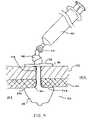
- FIG. 9depicts the anchor 20 in place within a body 100 .
- the inflator 60is connected to the anchor 20 at the connector 26 . Due to the small size of the anchor 20 , the inflator 60 may simply be a syringe capable of injecting into as well as removing a fluid from the anchor 20 .
- the fluidis air
- the ballooned region 24may be inflated and deflated upon application or removal of other fluids, both gaseous and liquid, including but not limited to water and saline.
- FIG. 9 embodimentit may be seen how the anchor 20 is used to secure the gastric wall 101 to the abdominal wall 102 by entering the patient's body 100 into the stomach or gastric lumen 103 through a stoma 104 created by the initial incision.
- the ballooned region 24may be preshaped so as to possess sufficiently small shoulder radii at regions 201 and 202 so that a face 203 may be created which is relatively flat in shape. This face would create a large resting or bearing surface to seat with the gastric wall 101 . The surface area of the face 203 working in conjunction with inflation of the ballooned region 24 would help minimize the likelihood of the anchor 20 from slipping out of the stoma 104 .
- Other desirable retention element shapesmay be created as well, depending upon the application.
- the overall geometry of the ballooned region 20may be bullet-shaped, disc-shaped, spherical, cylindrical, frustoconical or any other suitable shape limited only by the purpose intended and the skill of those in the art at forming preshaped balloons.
- the ballooned region 24properly situated and inflated, in many embodiments, including that of FIG. 9 , the proximal end 22 may simply be tied off.
- the reason that tying the anchor at the proximal end would be possibleis due to the small size of the anchor and the low inflation pressures needed to fully inflate the anchor once it is in place.
- the diameter of the shaft 23in many embodiments may be as small as from about 0.8 mm to about to 1.5 mm, and the ballooned region 24 may be considered fully inflated at pressures as low as from about 50 mbar to about 200 mbar.
- the anchor 20with a lengthening feature. This may prove useful and assist in deployment of the anchor from the introducer.
- inflationis first caused to extend the anchor longitudinally prior to any radial expansion of the ballooned region 24 .
- Such a featurewould enable the inflation process itself to deploy the ballooned region from the sheath.
- the introducermay be withdrawn from the body in any of the fashions described above and the ballooned region may continue to be inflated sufficiently so as to secure the anchor in place.
- This controlled expansionmay be accomplished by molding the ballooned region in a manner that will specifically cause it to deploy from the introducer, or by preloading the anchor within the introducer so that it will do the same.
- One possible technique which may be usedis to preload the introducer with the anchor, but to twist the anchor torsionally during the loading process and bunch up a portion of the anchor within the introducer. The twist would occlude the passage of the inflation fluid but would cause the anchor to move until such time as the twist were to clear the introducer. At that time, the anchor would untwist allowing the ballooned region to expand. Obviously folding the anchor without twisting may be made to accomplish the same effect.
- a plurality of anchorsare used in close proximity to one another.
- a gastropexy procedureoften three or four anchors are used in conjunction with one another.
- a gastrostomy tubeis often placed into the stomach lumen by making an additional incision at a location interior to the perimeter of the plurality of gastropexy devices.
- an individual retainermay be made to have the capability of securing more than one anchor 20 therein. That is, a single retainer may be used to secure two or more of the devices described above, so long as the devices were sufficiently closely spaced to one another.
Landscapes
- Health & Medical Sciences (AREA)
- Life Sciences & Earth Sciences (AREA)
- Heart & Thoracic Surgery (AREA)
- Animal Behavior & Ethology (AREA)
- General Health & Medical Sciences (AREA)
- Engineering & Computer Science (AREA)
- Biomedical Technology (AREA)
- Veterinary Medicine (AREA)
- Surgery (AREA)
- Public Health (AREA)
- Medical Informatics (AREA)
- Molecular Biology (AREA)
- Nuclear Medicine, Radiotherapy & Molecular Imaging (AREA)
- Biophysics (AREA)
- Pulmonology (AREA)
- Anesthesiology (AREA)
- Hematology (AREA)
- Rheumatology (AREA)
- Child & Adolescent Psychology (AREA)
- Media Introduction/Drainage Providing Device (AREA)
- Surgical Instruments (AREA)
- Orthopedics, Nursing, And Contraception (AREA)
Abstract
Description
Claims (11)
Priority Applications (7)
| Application Number | Priority Date | Filing Date | Title |
|---|---|---|---|
| US11/510,888US7582098B2 (en) | 2006-08-28 | 2006-08-28 | Percutaneous gastrointestinal anchoring kit |
| PCT/IB2007/052055WO2008026085A1 (en) | 2006-08-28 | 2007-05-31 | Percutaneous gastrointestinal anchoring kit |
| EP07766646.9AEP2056725B1 (en) | 2006-08-28 | 2007-05-31 | Percutaneous gastrointestinal anchoring kit |
| AU2007291012AAU2007291012B2 (en) | 2006-08-28 | 2007-05-31 | Percutaneous gastrointestinal anchoring kit |
| JP2009526204AJP5053379B2 (en) | 2006-08-28 | 2007-05-31 | Percutaneous gastrointestinal fixation kit |
| MX2009001047AMX2009001047A (en) | 2006-08-28 | 2007-05-31 | Percutaneous gastrointestinal anchoring kit. |
| CA2659347ACA2659347C (en) | 2006-08-28 | 2007-05-31 | Percutaneous gastrointestinal anchoring kit |
Applications Claiming Priority (1)
| Application Number | Priority Date | Filing Date | Title |
|---|---|---|---|
| US11/510,888US7582098B2 (en) | 2006-08-28 | 2006-08-28 | Percutaneous gastrointestinal anchoring kit |
Publications (2)
| Publication Number | Publication Date |
|---|---|
| US20080121553A1 US20080121553A1 (en) | 2008-05-29 |
| US7582098B2true US7582098B2 (en) | 2009-09-01 |
Family
ID=38566745
Family Applications (1)
| Application Number | Title | Priority Date | Filing Date |
|---|---|---|---|
| US11/510,888Active2027-05-10US7582098B2 (en) | 2006-08-28 | 2006-08-28 | Percutaneous gastrointestinal anchoring kit |
Country Status (7)
| Country | Link |
|---|---|
| US (1) | US7582098B2 (en) |
| EP (1) | EP2056725B1 (en) |
| JP (1) | JP5053379B2 (en) |
| AU (1) | AU2007291012B2 (en) |
| CA (1) | CA2659347C (en) |
| MX (1) | MX2009001047A (en) |
| WO (1) | WO2008026085A1 (en) |
Cited By (4)
| Publication number | Priority date | Publication date | Assignee | Title |
|---|---|---|---|---|
| US20080173568A1 (en)* | 2006-09-20 | 2008-07-24 | Mohamed Brageeth | Kit suitable for use in a surgical procedure and methods for using the same |
| US20090062743A1 (en)* | 2007-08-31 | 2009-03-05 | John Anthony Rotella | Gastropexy Kit |
| US10028731B2 (en) | 2013-11-12 | 2018-07-24 | Genzyme Corporation | Barrier application device |
| US10098628B2 (en) | 2014-07-22 | 2018-10-16 | Cook Medical Technologies Llc | Anchor deployment system, device, and method of treatment |
Families Citing this family (22)
| Publication number | Priority date | Publication date | Assignee | Title |
|---|---|---|---|---|
| US8523901B2 (en)* | 2007-08-14 | 2013-09-03 | Illuminoss Medical, Inc. | Apparatus and methods for attaching soft tissue to bone |
| US20100311026A1 (en) | 2009-06-03 | 2010-12-09 | Tomes Jennifer E | Catheter Tray, Packaging System, and Associated Methods |
| US20090254039A1 (en)* | 2007-12-21 | 2009-10-08 | O'brien Nicole Sams | Designer accessory for use with an intracorporeal medical device |
| US8678190B2 (en) | 2009-06-30 | 2014-03-25 | Medline Industries, Inc. | Catheter tray, packaging system, instruction insert, and associated methods |
| US8448786B2 (en) | 2009-06-30 | 2013-05-28 | Medline Industries, Inc. | Catheter tray, packaging system, instruction insert, and associated methods |
| US9795761B2 (en) | 2009-06-30 | 2017-10-24 | Medline Industries, Inc. | Medical kit, packaging system, instruction insert, and associated methods |
| US8631935B2 (en) | 2009-06-03 | 2014-01-21 | Medline Industries, Inc. | Catheter tray, packaging system, and associated methods |
| USD598538S1 (en)* | 2008-07-25 | 2009-08-18 | Yeakley Rourke M | Oral liquid medication device and container set |
| US8206368B2 (en)* | 2010-01-18 | 2012-06-26 | Rourke M. Yeakley | Multi-chamber mixture dispensing system |
| US8109917B2 (en)* | 2010-01-18 | 2012-02-07 | Rourke M. Yeakley | Twistable medication dispensing system |
| US10106295B2 (en) | 2010-05-21 | 2018-10-23 | Medline Industries, Inc. | Stacked catheter tray, system, and associated methods |
| USD704856S1 (en) | 2010-12-06 | 2014-05-13 | Medline Industries, Inc. | Medical tray |
| US10758705B2 (en) | 2013-10-16 | 2020-09-01 | C. R. Bard, Inc. | Catheter insertion tray with integrated instructions |
| WO2015122964A1 (en)* | 2014-02-11 | 2015-08-20 | Dexcom, Inc. | Packaging system for analyte sensors |
| EP3600120B1 (en) | 2017-03-31 | 2024-09-04 | C. R. Bard, Inc. | Catheter insertion-tray systems and methods thereof |
| DK4154802T3 (en) | 2017-06-19 | 2024-03-25 | Dexcom Inc | APPLICATORS FOR THE PLACEMENT OF TRANSCUTANEOUS ANALYTE SENSORS |
| CN110944705A (en) | 2018-04-24 | 2020-03-31 | C·R·巴德股份有限公司 | Urinary catheterization package and method thereof |
| US11116937B2 (en) | 2018-05-11 | 2021-09-14 | Medline Industries, Inc. | Foley catheter and corresponding single-layer tray packaging system |
| USD888252S1 (en) | 2018-06-18 | 2020-06-23 | Dexcom, Inc. | Transcutaneous analyte sensor applicator |
| JP7585047B2 (en) | 2018-06-20 | 2024-11-18 | シー・アール・バード・インコーポレーテッド | Urinary catheter insertion kit with integrated instructions for use and method thereof |
| WO2020223805A1 (en)* | 2019-05-06 | 2020-11-12 | Bles Biochemicals Incorporated | Feeding tube with integrated stylet |
| CN115670934A (en)* | 2022-10-27 | 2023-02-03 | 珠海原妙医学科技股份有限公司 | A gastrostomy device |
Citations (63)
| Publication number | Priority date | Publication date | Assignee | Title |
|---|---|---|---|---|
| US3253594A (en) | 1963-07-30 | 1966-05-31 | Frank E Matthews | Peritoneal cannula |
| US3397699A (en) | 1966-05-05 | 1968-08-20 | Gerald C. Kohl | Retaining catheter having resiliently biased wing flanges |
| US4077412A (en) | 1974-12-13 | 1978-03-07 | Moossun Mohamed H | Stomach intubation and catheter placement system |
| US4315513A (en) | 1980-03-10 | 1982-02-16 | Nawash Michael S | Gastrostomy and other percutaneous transport tubes |
| US4393873A (en) | 1980-03-10 | 1983-07-19 | Nawash Michael S | Gastrostomy and other percutaneous transport tubes |
| US4516968A (en) | 1982-09-28 | 1985-05-14 | Marshall Charles A | Catheter shield and method of use |
| US4666433A (en) | 1984-11-05 | 1987-05-19 | Medical Innovations Corporation | Gastrostomy feeding device |
| US4668225A (en) | 1985-12-23 | 1987-05-26 | Superior Healthcare Group, Inc. | Gastrostomy tube and gastrostomy-jejunal feeding tube combination |
| US4677967A (en) | 1984-11-01 | 1987-07-07 | New Mexico State University Foundation | Intravaginal anchor |
| US4685901A (en) | 1984-11-05 | 1987-08-11 | Medical Innovations Corporation | Gastro-jejunal feeding device |
| US4769004A (en) | 1987-03-02 | 1988-09-06 | Medivators, Inc. | Flexible tubing clamp and method of use |
| US4861334A (en) | 1988-06-24 | 1989-08-29 | Nawaz Arain | Self-retaining gastrostomy tube |
| US4986810A (en) | 1989-09-01 | 1991-01-22 | Neal Semrad | Toggle catheter |
| US5073166A (en) | 1989-02-15 | 1991-12-17 | Medical Innovations Corporation | Method and apparatus for emplacement of a gastrostomy catheter |
| US5112310A (en)* | 1991-02-06 | 1992-05-12 | Grobe James L | Apparatus and methods for percutaneous endoscopic gastrostomy |
| US5183464A (en) | 1991-05-17 | 1993-02-02 | Interventional Thermodynamics, Inc. | Radially expandable dilator |
| US5232440A (en) | 1992-02-26 | 1993-08-03 | Wilk Peter J | Method and device for draining abscess |
| US5234454A (en)* | 1991-08-05 | 1993-08-10 | Akron City Hospital | Percutaneous intragastric balloon catheter and method for controlling body weight therewith |
| US5267968A (en) | 1992-07-09 | 1993-12-07 | Russo Ronald D | Retention bolster for percutaneous catheters |
| US5273529A (en) | 1992-12-04 | 1993-12-28 | Olajire Idowu | Gastrostomy tube with expandable insertion tip |
| US5275610A (en) | 1991-05-13 | 1994-01-04 | Cook Incorporated | Surgical retractors and method of use |
| US5279564A (en) | 1992-09-11 | 1994-01-18 | Edward Weck Incorporated | Cannula retention device |
| US5290249A (en) | 1990-10-09 | 1994-03-01 | Vance Products Incorporated | Surgical access sheath |
| US5318542A (en) | 1992-01-08 | 1994-06-07 | Suddeutsche Feinmechanik Gmbh | Split cannula and process for the production thereof |
| US5356391A (en) | 1992-06-22 | 1994-10-18 | Medical Innovations Corp. | Flexible retainer flange for gastrostomy tube and the method of installing it |
| US5358488A (en) | 1993-11-16 | 1994-10-25 | Chinda Suriyapa | Device to control gastrostomy leakage |
| US5431676A (en) | 1993-03-05 | 1995-07-11 | Innerdyne Medical, Inc. | Trocar system having expandable port |
| US5439444A (en)* | 1991-01-28 | 1995-08-08 | Corpak, Inc. | Pre-formed member for percutaneous catheter |
| US5443449A (en) | 1991-03-01 | 1995-08-22 | Applied Medical Resources Corporation | Cholangiography catheter |
| US5484420A (en) | 1992-07-09 | 1996-01-16 | Wilson-Cook Medical Inc. | Retention bolsters for percutaneous catheters |
| US5507279A (en)* | 1993-11-30 | 1996-04-16 | Fortune; John B. | Retrograde endotracheal intubation kit |
| US5549657A (en) | 1994-05-12 | 1996-08-27 | C.R. Bard, Inc. | Low profile adaptor for gastrostomy feeding tube |
| WO1997025095A1 (en) | 1996-01-11 | 1997-07-17 | Radius International Limited Partnership | Corporeal access tube assembly and method |
| WO1998019730A1 (en) | 1996-11-04 | 1998-05-14 | Sherwood Medical Company | Coated radially expandable dilator for use with gastrointestinal-type tubes |
| WO1998026720A1 (en) | 1996-12-19 | 1998-06-25 | Tyco Group S.A.R.L. | Measuring device for use with a hemostatic puncture closure device |
| US6039714A (en) | 1998-05-12 | 2000-03-21 | Novartis Nutrition Ag | Collapsible retention bolster for gastrostomy and other ostomy tubes |
| US6090073A (en)* | 1995-05-17 | 2000-07-18 | Corpak, Inc. | Direct percutaneous endoscopic jejunostomy method and apparatus |
| EP1025802A1 (en) | 1999-02-08 | 2000-08-09 | Andrew H. Cragg | Percutaneous device anchoring system |
| WO2000050110A1 (en) | 1999-02-24 | 2000-08-31 | Sherwood Services Ag | Securing device for a low profile gastrostomy tube |
| US6186985B1 (en) | 1997-10-03 | 2001-02-13 | Boston Scientific Corporation | Gastro-intestinal tube with dissolvable support bolster |
| US6322538B1 (en) | 1999-02-18 | 2001-11-27 | Scimed Life Systems, Inc. | Gastro-intestinal tube placement device |
| US6387076B1 (en) | 1998-11-28 | 2002-05-14 | Smith Group Plc | Catheter retainers and assemblies |
| US6402722B1 (en) | 1997-10-01 | 2002-06-11 | Scimed Life Systems, Inc. | Apparatus and method for percutaneously placing gastrostomy tubes |
| WO2002058594A1 (en) | 2001-01-26 | 2002-08-01 | Jan Otto Solem | Anastomosis connecting apparatus |
| WO2002066108A1 (en) | 2001-02-15 | 2002-08-29 | Sherwood Services, Ag | Securing device for a low profile gastrostomy tube |
| US6458106B1 (en) | 2000-02-17 | 2002-10-01 | Sherwood Services, Ag | Low profile jejunal adapter for a gastrojejunal feeding system |
| US6471676B1 (en) | 2000-03-21 | 2002-10-29 | Novartis Nutrition Ag | Catheter and feeding tube retention device and method of use |
| US20020169360A1 (en) | 1998-07-16 | 2002-11-14 | Cardiothoracic Systems, Inc., A California Corporation | Surgical procedures and devices for increasing cardiac output of the heart |
| US6482183B1 (en) | 2000-05-10 | 2002-11-19 | Gudrun Pausch | Apparatus for the fixation of a percutaneous flexible line |
| US6582395B1 (en) | 2000-12-14 | 2003-06-24 | J & R Medical Devices, Inc. | Feeding tube device and method |
| WO2003092780A2 (en) | 2002-05-01 | 2003-11-13 | Boston Scientific Limited | Medical catheter assembly and method of using the same |
| WO2003094826A1 (en) | 2002-05-09 | 2003-11-20 | Scimed Life Systems, Inc. | Low profile adaptor for use with a medical catheter |
| US6673058B2 (en) | 2001-06-20 | 2004-01-06 | Scimed Life Systems, Inc. | Temporary dilating tip for gastro-intestinal tubes |
| US20040092796A1 (en) | 1999-10-14 | 2004-05-13 | John Butler | Wound retractor system |
| US20040097794A1 (en) | 1990-03-02 | 2004-05-20 | Bonutti Peter M. | Fluid operated retractors |
| US6743207B2 (en) | 2001-04-19 | 2004-06-01 | Scimed Life Systems, Inc. | Apparatus and method for the insertion of a medical device |
| US6765122B1 (en) | 2001-08-09 | 2004-07-20 | Cindy Kay Stout | Feeding tube skin guard |
| EP1077057B1 (en) | 1999-08-17 | 2004-07-28 | Sherwood Services AG | Shim device for enteral feeding system |
| US6769546B2 (en)* | 2002-07-03 | 2004-08-03 | L. John Busch | Epidural anesthesia kit |
| US20050216040A1 (en) | 2004-03-23 | 2005-09-29 | Michael Gertner | Devices and methods to treat a patient |
| WO2005110280A2 (en) | 2004-05-07 | 2005-11-24 | Valentx, Inc. | Devices and methods for attaching an endolumenal gastrointestinal implant |
| US20050267520A1 (en) | 2004-05-12 | 2005-12-01 | Modesitt D B | Access and closure device and method |
| US7264609B2 (en) | 2003-11-06 | 2007-09-04 | Hakky Said I | Indwelling urinary catheter |
Family Cites Families (2)
| Publication number | Priority date | Publication date | Assignee | Title |
|---|---|---|---|---|
| JP3675650B2 (en)* | 1997-10-14 | 2005-07-27 | シー・アール・バード・インコーポレーテッド | Body access tube |
| JP4841765B2 (en)* | 2001-08-01 | 2011-12-21 | 株式会社八光 | Gastrostomy catheter |
- 2006
- 2006-08-28USUS11/510,888patent/US7582098B2/enactiveActive
- 2007
- 2007-05-31JPJP2009526204Apatent/JP5053379B2/ennot_activeExpired - Fee Related
- 2007-05-31WOPCT/IB2007/052055patent/WO2008026085A1/enactiveApplication Filing
- 2007-05-31AUAU2007291012Apatent/AU2007291012B2/enactiveActive
- 2007-05-31EPEP07766646.9Apatent/EP2056725B1/enactiveActive
- 2007-05-31MXMX2009001047Apatent/MX2009001047A/enactiveIP Right Grant
- 2007-05-31CACA2659347Apatent/CA2659347C/enactiveActive
Patent Citations (65)
| Publication number | Priority date | Publication date | Assignee | Title |
|---|---|---|---|---|
| US3253594A (en) | 1963-07-30 | 1966-05-31 | Frank E Matthews | Peritoneal cannula |
| US3397699A (en) | 1966-05-05 | 1968-08-20 | Gerald C. Kohl | Retaining catheter having resiliently biased wing flanges |
| US4077412A (en) | 1974-12-13 | 1978-03-07 | Moossun Mohamed H | Stomach intubation and catheter placement system |
| US4315513A (en) | 1980-03-10 | 1982-02-16 | Nawash Michael S | Gastrostomy and other percutaneous transport tubes |
| US4393873A (en) | 1980-03-10 | 1983-07-19 | Nawash Michael S | Gastrostomy and other percutaneous transport tubes |
| US4516968A (en) | 1982-09-28 | 1985-05-14 | Marshall Charles A | Catheter shield and method of use |
| US4677967A (en) | 1984-11-01 | 1987-07-07 | New Mexico State University Foundation | Intravaginal anchor |
| US4666433A (en) | 1984-11-05 | 1987-05-19 | Medical Innovations Corporation | Gastrostomy feeding device |
| US4685901A (en) | 1984-11-05 | 1987-08-11 | Medical Innovations Corporation | Gastro-jejunal feeding device |
| US4668225A (en) | 1985-12-23 | 1987-05-26 | Superior Healthcare Group, Inc. | Gastrostomy tube and gastrostomy-jejunal feeding tube combination |
| US4769004A (en) | 1987-03-02 | 1988-09-06 | Medivators, Inc. | Flexible tubing clamp and method of use |
| US4861334A (en) | 1988-06-24 | 1989-08-29 | Nawaz Arain | Self-retaining gastrostomy tube |
| US5073166A (en) | 1989-02-15 | 1991-12-17 | Medical Innovations Corporation | Method and apparatus for emplacement of a gastrostomy catheter |
| US4986810A (en) | 1989-09-01 | 1991-01-22 | Neal Semrad | Toggle catheter |
| US20040097794A1 (en) | 1990-03-02 | 2004-05-20 | Bonutti Peter M. | Fluid operated retractors |
| US5290249A (en) | 1990-10-09 | 1994-03-01 | Vance Products Incorporated | Surgical access sheath |
| US5439444A (en)* | 1991-01-28 | 1995-08-08 | Corpak, Inc. | Pre-formed member for percutaneous catheter |
| US5112310A (en)* | 1991-02-06 | 1992-05-12 | Grobe James L | Apparatus and methods for percutaneous endoscopic gastrostomy |
| US5443449A (en) | 1991-03-01 | 1995-08-22 | Applied Medical Resources Corporation | Cholangiography catheter |
| US5275610A (en) | 1991-05-13 | 1994-01-04 | Cook Incorporated | Surgical retractors and method of use |
| US5183464A (en) | 1991-05-17 | 1993-02-02 | Interventional Thermodynamics, Inc. | Radially expandable dilator |
| US5234454A (en)* | 1991-08-05 | 1993-08-10 | Akron City Hospital | Percutaneous intragastric balloon catheter and method for controlling body weight therewith |
| US5318542A (en) | 1992-01-08 | 1994-06-07 | Suddeutsche Feinmechanik Gmbh | Split cannula and process for the production thereof |
| US5232440A (en) | 1992-02-26 | 1993-08-03 | Wilk Peter J | Method and device for draining abscess |
| US5356391A (en) | 1992-06-22 | 1994-10-18 | Medical Innovations Corp. | Flexible retainer flange for gastrostomy tube and the method of installing it |
| US5484420A (en) | 1992-07-09 | 1996-01-16 | Wilson-Cook Medical Inc. | Retention bolsters for percutaneous catheters |
| US5267968A (en) | 1992-07-09 | 1993-12-07 | Russo Ronald D | Retention bolster for percutaneous catheters |
| US5279564A (en) | 1992-09-11 | 1994-01-18 | Edward Weck Incorporated | Cannula retention device |
| US5273529A (en) | 1992-12-04 | 1993-12-28 | Olajire Idowu | Gastrostomy tube with expandable insertion tip |
| US5431676A (en) | 1993-03-05 | 1995-07-11 | Innerdyne Medical, Inc. | Trocar system having expandable port |
| US5358488A (en) | 1993-11-16 | 1994-10-25 | Chinda Suriyapa | Device to control gastrostomy leakage |
| US5507279A (en)* | 1993-11-30 | 1996-04-16 | Fortune; John B. | Retrograde endotracheal intubation kit |
| US5549657A (en) | 1994-05-12 | 1996-08-27 | C.R. Bard, Inc. | Low profile adaptor for gastrostomy feeding tube |
| US6090073A (en)* | 1995-05-17 | 2000-07-18 | Corpak, Inc. | Direct percutaneous endoscopic jejunostomy method and apparatus |
| WO1997025095A1 (en) | 1996-01-11 | 1997-07-17 | Radius International Limited Partnership | Corporeal access tube assembly and method |
| US5860960A (en) | 1996-01-11 | 1999-01-19 | C. R. Bard, Inc. | Bolster for corporeal access tube assembly |
| WO1998019730A1 (en) | 1996-11-04 | 1998-05-14 | Sherwood Medical Company | Coated radially expandable dilator for use with gastrointestinal-type tubes |
| WO1998026720A1 (en) | 1996-12-19 | 1998-06-25 | Tyco Group S.A.R.L. | Measuring device for use with a hemostatic puncture closure device |
| US6402722B1 (en) | 1997-10-01 | 2002-06-11 | Scimed Life Systems, Inc. | Apparatus and method for percutaneously placing gastrostomy tubes |
| US6186985B1 (en) | 1997-10-03 | 2001-02-13 | Boston Scientific Corporation | Gastro-intestinal tube with dissolvable support bolster |
| US6039714A (en) | 1998-05-12 | 2000-03-21 | Novartis Nutrition Ag | Collapsible retention bolster for gastrostomy and other ostomy tubes |
| US20020169360A1 (en) | 1998-07-16 | 2002-11-14 | Cardiothoracic Systems, Inc., A California Corporation | Surgical procedures and devices for increasing cardiac output of the heart |
| US6387076B1 (en) | 1998-11-28 | 2002-05-14 | Smith Group Plc | Catheter retainers and assemblies |
| EP1025802A1 (en) | 1999-02-08 | 2000-08-09 | Andrew H. Cragg | Percutaneous device anchoring system |
| US6322538B1 (en) | 1999-02-18 | 2001-11-27 | Scimed Life Systems, Inc. | Gastro-intestinal tube placement device |
| WO2000050110A1 (en) | 1999-02-24 | 2000-08-31 | Sherwood Services Ag | Securing device for a low profile gastrostomy tube |
| EP1077057B1 (en) | 1999-08-17 | 2004-07-28 | Sherwood Services AG | Shim device for enteral feeding system |
| US20040092796A1 (en) | 1999-10-14 | 2004-05-13 | John Butler | Wound retractor system |
| US6458106B1 (en) | 2000-02-17 | 2002-10-01 | Sherwood Services, Ag | Low profile jejunal adapter for a gastrojejunal feeding system |
| US6471676B1 (en) | 2000-03-21 | 2002-10-29 | Novartis Nutrition Ag | Catheter and feeding tube retention device and method of use |
| US6482183B1 (en) | 2000-05-10 | 2002-11-19 | Gudrun Pausch | Apparatus for the fixation of a percutaneous flexible line |
| US6582395B1 (en) | 2000-12-14 | 2003-06-24 | J & R Medical Devices, Inc. | Feeding tube device and method |
| WO2002058594A1 (en) | 2001-01-26 | 2002-08-01 | Jan Otto Solem | Anastomosis connecting apparatus |
| WO2002066108A1 (en) | 2001-02-15 | 2002-08-29 | Sherwood Services, Ag | Securing device for a low profile gastrostomy tube |
| US20040193114A1 (en) | 2001-04-19 | 2004-09-30 | Elbert Linda D. | Apparatus and method for the insertion of a medical device |
| US6743207B2 (en) | 2001-04-19 | 2004-06-01 | Scimed Life Systems, Inc. | Apparatus and method for the insertion of a medical device |
| US6673058B2 (en) | 2001-06-20 | 2004-01-06 | Scimed Life Systems, Inc. | Temporary dilating tip for gastro-intestinal tubes |
| US6765122B1 (en) | 2001-08-09 | 2004-07-20 | Cindy Kay Stout | Feeding tube skin guard |
| WO2003092780A2 (en) | 2002-05-01 | 2003-11-13 | Boston Scientific Limited | Medical catheter assembly and method of using the same |
| WO2003094826A1 (en) | 2002-05-09 | 2003-11-20 | Scimed Life Systems, Inc. | Low profile adaptor for use with a medical catheter |
| US6769546B2 (en)* | 2002-07-03 | 2004-08-03 | L. John Busch | Epidural anesthesia kit |
| US7264609B2 (en) | 2003-11-06 | 2007-09-04 | Hakky Said I | Indwelling urinary catheter |
| US20050216040A1 (en) | 2004-03-23 | 2005-09-29 | Michael Gertner | Devices and methods to treat a patient |
| WO2005110280A2 (en) | 2004-05-07 | 2005-11-24 | Valentx, Inc. | Devices and methods for attaching an endolumenal gastrointestinal implant |
| US20050267520A1 (en) | 2004-05-12 | 2005-12-01 | Modesitt D B | Access and closure device and method |
Cited By (6)
| Publication number | Priority date | Publication date | Assignee | Title |
|---|---|---|---|---|
| US20080173568A1 (en)* | 2006-09-20 | 2008-07-24 | Mohamed Brageeth | Kit suitable for use in a surgical procedure and methods for using the same |
| US20090062743A1 (en)* | 2007-08-31 | 2009-03-05 | John Anthony Rotella | Gastropexy Kit |
| US8157816B2 (en)* | 2007-08-31 | 2012-04-17 | Kimberly-Clark Worldwide, Inc. | Gastropexy kit |
| US8382772B2 (en) | 2007-08-31 | 2013-02-26 | Kimberly-Clark Worldwide, Inc. | Gastropexy kit |
| US10028731B2 (en) | 2013-11-12 | 2018-07-24 | Genzyme Corporation | Barrier application device |
| US10098628B2 (en) | 2014-07-22 | 2018-10-16 | Cook Medical Technologies Llc | Anchor deployment system, device, and method of treatment |
Also Published As
| Publication number | Publication date |
|---|---|
| JP5053379B2 (en) | 2012-10-17 |
| AU2007291012B2 (en) | 2013-05-02 |
| MX2009001047A (en) | 2009-02-10 |
| CA2659347A1 (en) | 2008-03-06 |
| US20080121553A1 (en) | 2008-05-29 |
| JP2010502247A (en) | 2010-01-28 |
| CA2659347C (en) | 2013-03-12 |
| AU2007291012A1 (en) | 2008-03-06 |
| WO2008026085A1 (en) | 2008-03-06 |
| EP2056725B1 (en) | 2013-09-25 |
| EP2056725A1 (en) | 2009-05-13 |
Similar Documents
| Publication | Publication Date | Title |
|---|---|---|
| US7582098B2 (en) | Percutaneous gastrointestinal anchoring kit | |
| US8147449B2 (en) | Device for gastric feeding and drainage via an artificial stoma | |
| EP2073720B1 (en) | A tissue to tissue anchoring device | |
| EP2056922B1 (en) | In-dwelling port for access into a body | |
| EP2101651B1 (en) | Segmented tissue-to-tissue anchoring device |
Legal Events
| Date | Code | Title | Description |
|---|---|---|---|
| AS | Assignment | Owner name:KIMBERLY-CLARK WORLDWIDE, INC., WISCONSIN Free format text:ASSIGNMENT OF ASSIGNORS INTEREST;ASSIGNOR:GOBEL, FRED;REEL/FRAME:018432/0559 Effective date:20061022 Owner name:KIMBERLY-CLARK WORLDWIDE, INC., WISCONSIN Free format text:ASSIGNMENT OF ASSIGNORS INTEREST;ASSIGNOR:GOBEL, FRED;REEL/FRAME:018432/0343 Effective date:20061022 | |
| STCF | Information on status: patent grant | Free format text:PATENTED CASE | |
| CC | Certificate of correction | ||
| FPAY | Fee payment | Year of fee payment:4 | |
| AS | Assignment | Owner name:AVENT, INC., GEORGIA Free format text:ASSIGNMENT OF ASSIGNORS INTEREST;ASSIGNOR:KIMBERLY-CLARK WORLDWIDE, INC.;REEL/FRAME:034753/0360 Effective date:20141030 | |
| AS | Assignment | Owner name:MORGAN STANLEY SENIOR FUNDING, INC., NEW YORK Free format text:SECURITY INTEREST;ASSIGNOR:AVENT, INC.;REEL/FRAME:035375/0867 Effective date:20150227 | |
| FPAY | Fee payment | Year of fee payment:8 | |
| AS | Assignment | Owner name:CITIBANK, N.A., NEW YORK Free format text:INTELLECTUAL PROPERTY SECURITY INTEREST ASSIGNMENT AGREEMENT;ASSIGNOR:MORGAN STANLEY SENIOR FUNDING, INC.;REEL/FRAME:048173/0137 Effective date:20181029 | |
| MAFP | Maintenance fee payment | Free format text:PAYMENT OF MAINTENANCE FEE, 12TH YEAR, LARGE ENTITY (ORIGINAL EVENT CODE: M1553); ENTITY STATUS OF PATENT OWNER: LARGE ENTITY Year of fee payment:12 | |
| AS | Assignment | Owner name:JPMORGAN CHASE BANK, N.A., AS ADMINISTRATIVE AGENT, ILLINOIS Free format text:SECURITY INTEREST;ASSIGNOR:AVENT, INC.;REEL/FRAME:060441/0445 Effective date:20220624 | |
| AS | Assignment | Owner name:AVANOS MEDICAL SALES, LLC, GEORGIA Free format text:RELEASE BY SECURED PARTY;ASSIGNOR:CITIBANK, N.A.;REEL/FRAME:060557/0062 Effective date:20220624 Owner name:AVENT, INC., GEORGIA Free format text:RELEASE BY SECURED PARTY;ASSIGNOR:CITIBANK, N.A.;REEL/FRAME:060557/0062 Effective date:20220624 |