US7582093B2 - Screw extraction and insertion device - Google Patents
Screw extraction and insertion deviceDownload PDFInfo
- Publication number
- US7582093B2 US7582093B2US11/115,009US11500905AUS7582093B2US 7582093 B2US7582093 B2US 7582093B2US 11500905 AUS11500905 AUS 11500905AUS 7582093 B2US7582093 B2US 7582093B2
- Authority
- US
- United States
- Prior art keywords
- shaft sleeve
- screw
- proximal
- distal
- longitudinal axis
- Prior art date
- Legal status (The legal status is an assumption and is not a legal conclusion. Google has not performed a legal analysis and makes no representation as to the accuracy of the status listed.)
- Expired - Fee Related, expires
Links
- 238000000605extractionMethods0.000titleclaimsabstractdescription29
- 238000003780insertionMethods0.000titleclaimsabstractdescription22
- 230000037431insertionEffects0.000titleclaimsabstractdescription22
- 239000000463materialSubstances0.000claimsdescription5
- 229910001220stainless steelInorganic materials0.000claimsdescription2
- 239000010935stainless steelSubstances0.000claimsdescription2
- 238000000034methodMethods0.000abstractdescription11
- 210000000988bone and boneAnatomy0.000description28
- 230000033001locomotionEffects0.000description4
- 208000010392Bone FracturesDiseases0.000description2
- 230000008878couplingEffects0.000description2
- 238000010168coupling processMethods0.000description2
- 238000005859coupling reactionMethods0.000description2
- 238000002513implantationMethods0.000description2
- 238000012986modificationMethods0.000description2
- 230000004048modificationEffects0.000description2
- 238000004519manufacturing processMethods0.000description1
- 238000003825pressingMethods0.000description1
- 210000004872soft tissueAnatomy0.000description1
- 230000008467tissue growthEffects0.000description1
Images


Classifications
- B—PERFORMING OPERATIONS; TRANSPORTING
- B25—HAND TOOLS; PORTABLE POWER-DRIVEN TOOLS; MANIPULATORS
- B25B—TOOLS OR BENCH DEVICES NOT OTHERWISE PROVIDED FOR, FOR FASTENING, CONNECTING, DISENGAGING OR HOLDING
- B25B23/00—Details of, or accessories for, spanners, wrenches, screwdrivers
- B25B23/02—Arrangements for handling screws or nuts
- B25B23/08—Arrangements for handling screws or nuts for holding or positioning screw or nut prior to or during its rotation
- B25B23/10—Arrangements for handling screws or nuts for holding or positioning screw or nut prior to or during its rotation using mechanical gripping means
- B25B23/101—Arrangements for handling screws or nuts for holding or positioning screw or nut prior to or during its rotation using mechanical gripping means for hand-driven screw-drivers
- A—HUMAN NECESSITIES
- A61—MEDICAL OR VETERINARY SCIENCE; HYGIENE
- A61B—DIAGNOSIS; SURGERY; IDENTIFICATION
- A61B17/00—Surgical instruments, devices or methods
- A61B17/56—Surgical instruments or methods for treatment of bones or joints; Devices specially adapted therefor
- A61B17/58—Surgical instruments or methods for treatment of bones or joints; Devices specially adapted therefor for osteosynthesis, e.g. bone plates, screws or setting implements
- A61B17/88—Osteosynthesis instruments; Methods or means for implanting or extracting internal or external fixation devices
- A61B17/8875—Screwdrivers, spanners or wrenches
- A61B17/8886—Screwdrivers, spanners or wrenches holding the screw head
- A61B17/8891—Screwdrivers, spanners or wrenches holding the screw head at its periphery
- A—HUMAN NECESSITIES
- A61—MEDICAL OR VETERINARY SCIENCE; HYGIENE
- A61B—DIAGNOSIS; SURGERY; IDENTIFICATION
- A61B17/00—Surgical instruments, devices or methods
- A61B17/56—Surgical instruments or methods for treatment of bones or joints; Devices specially adapted therefor
- A61B17/58—Surgical instruments or methods for treatment of bones or joints; Devices specially adapted therefor for osteosynthesis, e.g. bone plates, screws or setting implements
- A61B17/88—Osteosynthesis instruments; Methods or means for implanting or extracting internal or external fixation devices
- A61B17/8872—Instruments for putting said fixation devices against or away from the bone
Definitions
- This inventionrelates to tools used for the extraction and insertion of screws, having particular application in the medical field where screws are inserted and/or extracted as part of a medical procedure.
- U.S. Pat. No. 4,463,753describes a bone screw having distal threads and proximal threads. That bone screw is specifically intended for repair of a fracture by compressing the fractured segments of a bone while maintaining proper bone alignment. An end of the screw is provided with a hexagonal bore for engaging an Allen wrench, which can then be used for inserting the bone screw.
- an Allen wrenchcannot be used for exerting a pulling force for forcibly removing the bone screw.
- U.S. Pat. No. 5,375,956discloses a bone screw having a smooth shaft with threads near the head of the screw, as well as reverse threads extending about the head of the screw for engaging an internally-threaded extraction device.
- the screwcan be removed by driving the extraction device onto the reverse threads to an engagement limit, at which point the extraction device can be further driven for partial extraction of the screw from the bone.
- the screwis pulled until the remaining smooth shaft is extracted.
- the engagement of the internal threads of the extraction device with the external threads of the screw headallows the extraction device to be used for exerting a pulling force for extracting the smooth shaft of the screw from the bone.
- the internally-threaded screw extractorstill presents several drawbacks.
- the use of the internally-threaded screw extractorrequires the use of a screw having a threaded screw head, thus adding to the complexity and expense of manufacturing the bone screw.
- tissue growthoften occurs in the threads of the screw head while it is in place, making it difficult to thread the extractor onto the screw for removal.
- a device for screw insertion and extractionis presented herein that can be used for exerting a pulling force for removal of a screw without requiring that the screw head be threaded.
- a screw extraction and insertion devicecomprises a shaft sleeve for engaging the shaft of a wrench.
- the shaft sleeveextends along a longitudinal axis, and has a proximal portion and a distal portion. The proximal and distal portions are adjacent to respective opposing sides of the wrench shaft when the shaft sleeve is engaged with the wrench shaft.
- the devicealso comprises a shoulder extending radially inward from a distal end of the shaft sleeve.
- a screw extraction and insertion devicecomprises a shaft sleeve having a proximal portion and a distal portion connected by an intermediate portion. At least part of the proximal portion extends along a first longitudinal axis, and at least part the distal portion extends along a second longitudinal axis parallel to and offset from the first longitudinal axis.
- the devicealso comprises a shoulder that extends from the distal portion towards the first longitudinal axis.
- FIGS. 1A and 1Bshow perspective views of respective sides of a first embodiment of a screw extraction/insertion device
- FIG. 1Cshows an enlarged perspective view of a distal end of the screw extraction/insertion device shown in FIGS. 1A and 1B ;
- FIGS. 2A and 2Bshow a perspective view and an enlarged perspective view, respectively, of the screw extraction/insertion device shown in FIGS. 1A-1C while engaging a screw;
- FIGS. 3A-3Dshow steps for engaging a screw using the screw extraction device
- FIGS. 4A and 4Bshow perspective views of a second embodiment of the screw extraction device.
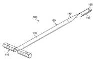
- a screw extractor 100is shown that can serve as a wrench frame for assisting in maintaining a secure coupling between a wrench and a screw.
- the screw extractor 100is particularly useful for screw extraction procedures.
- the term “extractor”is merely a term of convenience and thus is not intended to limit in any way the scope of the present invention.
- the screw extractor 100is preferably constructed of a rigid material, for example stainless steel.
- the screw extractor 100includes a handle 110 and a shaft sleeve 120 .
- the shaft sleeve 120has a form that allows it to be engaged with a wrench shaft 310 even while the wrench 300 is engaged with a screw 200 .
- the shaft sleeve 120includes a proximal portion 130 , an intermediate portion 140 , and a distal portion 150 .
- the proximal portion 130 and distal portion 150are both generally semi-cylindrical in order to provide a secure interface with the cylindrical shaft of a wrench.
- alternate shapes the shaft sleeve 120can be implemented without departing from the spirit and scope of the present invention, particularly where an alternate shape is desired for accommodating the shape of a wrench shaft.
- the shaft sleeve 120can include portion or portions having a parabolic, curved, curvilinear, semipolygonal (i.e., multi-faceted), U, V, or C-shaped cross section.
- the semi-cylindrical shapeis preferable for providing a secure interface with a cylindrical wrench shaft (e.g., wrench shaft 310 shown in FIGS. 3A-D ) and for providing a low profile for passage into soft tissue en route to a screw secured in a bone.
- a cylindrical wrench shafte.g., wrench shaft 310 shown in FIGS. 3A-D
- the semi-cylindrical component of the proximal portion 130 and the distal portion 150are offset from each other by an angle of approximately 180 degrees about a longitudinal axis of the shaft sleeve 120 .
- the intermediate portion 140is generally semi-cylindrical, but forms a helical shape that twists approximately 180 degrees over the length thereof according to the angular offset between the distal portion 130 and the proximal portion 150 .
- the proximal portion 130can be angularly offset from the distal portion 150 by other angles about the longitudinal axis of the shaft sleeve 120 , or even aligned. However, the offset as shown in FIGS.
- 1A-1Cis preferred since it allows the shaft sleeve 120 to more securely engage the wrench shaft 310 by extending longitudinally along opposing sides of the wrench shaft 310 .
- a shoulder 160is provided at a distal end of the distal portion 150 .
- the shoulder 160extends radially inward from the shaft sleeve 120 .
- the screw extractor 100can be used for aiding in the removal and/or implantation of surgical screws.
- the screw extractor 100can be used for removal and/or implantation of a peg-design (i.e., smooth shaft) locking screw 200 shown in FIGS. 2A and 2B .
- the screw 200can be used for fixing the position of an intramedullary nail (not shown).
- the locking screw 200has a screw head 210 having a hexagonal recess 215 for driving engagement by an Allen-head wrench 300 (shown in FIGS. 3A-3D ).
- Allen-head wrench 300shown in FIGS. 3A-3D
- other types or styles of recess/wrench combinationscan be used, for example slotted, Phillips, Torx, or square.
- the locking screw 200also has a screw shaft 220 extending longitudinally from the screw head 210 .
- the screw shaft 220is smoothly cylindrical except for a threaded portion 230 .
- the threaded portion 230is preferably distanced longitudinally from the screw head 210 sufficiently enough to allow space for the shoulder 160 of the screw extractor 100 to engage the locking screw 200 .
- the screw head 210preferably has an outer diameter that is greater than an outer diameter of the screw shaft 220 , or at least a portion of the screw shaft 220 adjacent to the screw head 210 , in order to allow the shoulder 160 to engage the screw 200 at the base of the screw head 210 .
- the inner diameter of the distal portion 150 of the shaft sleeve 120is preferably equal to or slightly greater than the outer diameter of the screw head 210 in order to allow the screw head 210 to be accommodated by the distal portion 150 of the shaft sleeve 120 .
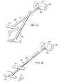
- a method of using the screw extractor 100 for extracting a bone screw such as bone screw 200will now be discussed in conjunction with FIGS. 3A-3D .
- the locking screw 200is removed by turning the screw counter-clockwise until the threaded portion 230 backs out of the bone 400 .
- the screw 200must be pulled in order to extract the smooth portion of the screw shaft 220 from the bone 400 . Frictional forces between the bone 400 and the screw shaft 220 usually inhibit easy extraction.
- the screw extractor 100provides a secure capture of the screw 200 , particularly when used in combination with the wrench 300 , for pulling the screw 200 from the bone 400 . It will be appreciated that the screw extractor 100 can be similarly used for inserting the screw 200 into the bone 400 .
- the wrench 300is engaged with the screw 200 , which has been turned to the point that the threaded portion 230 has been backed out of the bone 400 . That is, in FIG. 3A the screw head 210 and threaded portion 230 are shown external to the bone 400 while the screw shaft 220 (shown in broken lines) remains in the bone.
- the screw extractor 100is employed for extracting the screw 200 by pulling on the screw 200 until the screw shaft 220 exits the bone 400 . As shown in FIG. 3A , the screw extractor 100 is positioned for placement over the wrench shaft 310 .
- the intermediate portion 140 of the shaft sleeve 120is placed adjacent to the wrench shaft 310 with the inner side of the semi-cylindrical proximal and distal portions 130 and 150 facing the wrench shaft 310 .
- the screw extractor 100is initially positioned such that the shaft sleeve 120 extends at an angle to the longitudinal axis of the wrench shaft 310 .
- the screw extractor 100is tilted relative to the wrench 300 in the direction indicated by arrow A. The tilting motion is continued until the longitudinal axis of the shaft sleeve 120 is close to parallel with the longitudinal axis of the wrench shaft 310 as shown in FIG. 3B .
- the screw extractor 100is slid along the wrench shaft 310 towards the screw 200 in the direction indicated by arrow B.
- the wrench shaft 310guides the shaft sleeve 120 directly to the screw 200 so long as the shaft sleeve 120 remains in contact with the wrench 300 , and the wrench 300 remains engaged with the screw 200 .
- the screw extractor 100is slid relative to the wrench 300 in the direction B until the handle 110 of the screw extractor 100 arrives at the handle 320 of the wrench 300 .
- the extractor handle 110is moved under the wrench handle 320 to the position shown in FIG. 3D in a motion as generally indicated by the arrow C in FIG. 3C .
- the motion of the extractor handle 110 over the wrench handle 320simultaneously moves the distal end of the shaft sleeve 120 , moving the shoulder 160 of the shaft sleeve 120 behind the screw head 210 .
- This movementcaptures the screw head 160 , locking the screw head 210 between the wrench shaft 310 and the shoulder 160 of the shaft sleeve 120 .
- both the screw extractor 100 and wrench 300can be pulled as shown in FIG. 3D in the direction indicated by arrow D to extract the screw 200 from the bone 400 .
- the extractor 100can also be used for screw insertion procedures.
- the extractor 100can be assembled with the screw 200 and the wrench 300 in order to securely capture the screw head 210 and maintain engagement between the screw 200 and the wrench 300 .
- the screw shaft 220can be pushed into a pre-drilled hole in the bone 400 to the position shown in FIG. 3D .
- the extractor 100can then be removed from the wrench 300 by following the steps outlined above in connection with FIGS. 3A-3D in reverse order.
- the form of the extractor 100advantageously allows the extractor 100 to be disengaged from the wrench 300 while the wrench 300 remains engaged with the screw 200 .
- the wrench 300can readily be used for driving the threaded portion 230 of the screw 200 into the bone 400 .
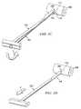
- the screw extractor 500includes modified forms of features included in the screw extractor 100 , such as an alternate handle 510 , shaft sleeve 520 , and shoulder 560 , as well as an optional collar 570 . Any one or more of these modified features can be incorporated into the screw extractor 100 .
- the shaft sleeve 520forms a semi-circular channel that extends in a longitudinal direction between distal and proximal ends thereof.
- the handle 510extends from the proximal end of the shaft sleeve 520 and the shoulder 560 extends from the distal end, the handle 510 and shoulder 560 extending in opposite directions.
- the shoulder 560is a crescent-shaped member for engaging the base of the screw head as shown in FIG. 4B .
- the collar 570extends from the shaft sleeve 520 longitudinally offset from the shoulder 560 by a distance sufficient to accommodate the screw head 210 , allowing for the screw extractor 500 to engage the screw 200 as shown in FIG. 4B .
- the collar 570assists in providing a secure coupling with the screw 200 .
- the collar 570serves as a surface for applying pressure against the screw head 210 .
- the collar 570defines an aperture that allows the wrench 300 to engage and drive the screw 200 .
- the collar 570would completely circumscribe the shaft of the wrench 300 , it will be appreciated that this configuration does not allow for the screw extractor 500 to be engaged/disengaged from the wrench 300 while the wrench 300 is engaged with the screw 200 .
- the collar 570can instead have crescent shape similar to that of the shoulder 560 , which would allow for the screw extractor 500 to be engaged/disengaged from the wrench 300 while the wrench 300 is engaged with the screw 200 .
Landscapes
- Health & Medical Sciences (AREA)
- Surgery (AREA)
- Engineering & Computer Science (AREA)
- Orthopedic Medicine & Surgery (AREA)
- Life Sciences & Earth Sciences (AREA)
- Heart & Thoracic Surgery (AREA)
- Nuclear Medicine, Radiotherapy & Molecular Imaging (AREA)
- Biomedical Technology (AREA)
- Mechanical Engineering (AREA)
- Medical Informatics (AREA)
- Molecular Biology (AREA)
- Animal Behavior & Ethology (AREA)
- General Health & Medical Sciences (AREA)
- Public Health (AREA)
- Veterinary Medicine (AREA)
- Surgical Instruments (AREA)
- Hand Tools For Fitting Together And Separating, Or Other Hand Tools (AREA)
- Details Of Spanners, Wrenches, And Screw Drivers And Accessories (AREA)
Abstract
Description
Claims (20)
Priority Applications (6)
| Application Number | Priority Date | Filing Date | Title |
|---|---|---|---|
| US11/115,009US7582093B2 (en) | 2005-04-26 | 2005-04-26 | Screw extraction and insertion device |
| ES06758571.1TES2439452T3 (en) | 2005-04-26 | 2006-04-25 | Screw extraction and insertion device |
| PCT/US2006/015602WO2006116388A2 (en) | 2005-04-26 | 2006-04-25 | Screw extraction and insertion device |
| EP06758571.1AEP1874207B1 (en) | 2005-04-26 | 2006-04-25 | Screw extraction and insertion device |
| AU2006238831AAU2006238831B2 (en) | 2005-04-26 | 2006-04-25 | Screw extraction and insertion device |
| JP2008509036AJP2008539021A (en) | 2005-04-26 | 2006-04-25 | Screw extraction and insertion device |
Applications Claiming Priority (1)
| Application Number | Priority Date | Filing Date | Title |
|---|---|---|---|
| US11/115,009US7582093B2 (en) | 2005-04-26 | 2005-04-26 | Screw extraction and insertion device |
Publications (2)
| Publication Number | Publication Date |
|---|---|
| US20060241649A1 US20060241649A1 (en) | 2006-10-26 |
| US7582093B2true US7582093B2 (en) | 2009-09-01 |
Family
ID=37187991
Family Applications (1)
| Application Number | Title | Priority Date | Filing Date |
|---|---|---|---|
| US11/115,009Expired - Fee RelatedUS7582093B2 (en) | 2005-04-26 | 2005-04-26 | Screw extraction and insertion device |
Country Status (6)
| Country | Link |
|---|---|
| US (1) | US7582093B2 (en) |
| EP (1) | EP1874207B1 (en) |
| JP (1) | JP2008539021A (en) |
| AU (1) | AU2006238831B2 (en) |
| ES (1) | ES2439452T3 (en) |
| WO (1) | WO2006116388A2 (en) |
Cited By (2)
| Publication number | Priority date | Publication date | Assignee | Title |
|---|---|---|---|---|
| US20100237300A1 (en)* | 2009-03-17 | 2010-09-23 | Raytheon Company | Leverage Tool for a Crank Assembly of a Radar System |
| US8992586B2 (en) | 2011-07-20 | 2015-03-31 | Michael H. Horwitz | Minimal incision removable bone screw, driver, and method of use |
Families Citing this family (10)
| Publication number | Priority date | Publication date | Assignee | Title |
|---|---|---|---|---|
| US7909830B2 (en) | 2005-08-25 | 2011-03-22 | Synthes Usa, Llc | Methods of spinal fixation and instrumentation |
| US20080221623A1 (en)* | 2005-10-17 | 2008-09-11 | Gooch Hubert L | Systems and Methods for the Medical Treatment of Structural Tissue |
| WO2007121271A2 (en)* | 2006-04-11 | 2007-10-25 | Synthes (U.S.A) | Minimally invasive fixation system |
| EP2206470A3 (en)* | 2008-05-21 | 2011-01-12 | Hubert L. Gooch | Systems for the medical treatment of structural tissue |
| CN102497828B (en) | 2009-05-20 | 2015-09-09 | 斯恩蒂斯有限公司 | What patient installed retracts part |
| US8535318B2 (en) | 2010-04-23 | 2013-09-17 | DePuy Synthes Products, LLC | Minimally invasive instrument set, devices and related methods |
| CN103717159B (en) | 2011-05-27 | 2016-08-17 | 新特斯有限责任公司 | Minimally Invasive Spinal Fixation System Including Vertebral Alignment Features |
| USD679012S1 (en)* | 2012-06-29 | 2013-03-26 | Richard P. Gleixner | Intramedullary implant extractor |
| USD679394S1 (en)* | 2012-07-02 | 2013-04-02 | Richard P. Gleixner | Intramedullary implant extractor |
| WO2020033625A1 (en)* | 2018-08-08 | 2020-02-13 | Innomed One, Llc | Artificial insemination system |
Citations (19)
| Publication number | Priority date | Publication date | Assignee | Title |
|---|---|---|---|---|
| US758017A (en)* | 1904-02-03 | 1904-04-19 | W G Browne Mfg Company | Tack-claw. |
| US4454876A (en)* | 1982-05-25 | 1984-06-19 | University Of Pittsburgh | Pelvic fixation plate and method of implanting same |
| US4463753A (en) | 1980-01-04 | 1984-08-07 | Gustilo Ramon B | Compression bone screw |
| US4485944A (en)* | 1982-04-27 | 1984-12-04 | Central Quality Industries, Inc. | Dispenser with quick-release drive screw |
| US4948369A (en)* | 1987-05-19 | 1990-08-14 | General Electric Company | Connector assembly |
| US4977661A (en)* | 1989-08-07 | 1990-12-18 | Wood Thomas H | Carrier bearing and axle bearing puller |
| US5375956A (en) | 1993-03-11 | 1994-12-27 | Pennig; Dietmar | Head screw construction for use in fixing the position of an intramedullary nail |
| US5498265A (en) | 1991-03-05 | 1996-03-12 | Howmedica Inc. | Screw and driver |
| US5658289A (en)* | 1993-09-24 | 1997-08-19 | Linvatec Corporation | Ligament graft protection apparatus and method |
| US5667513A (en)* | 1995-06-07 | 1997-09-16 | Smith & Nephew Dyonics Inc. | Soft tissue anchor delivery apparatus |
| US5690639A (en)* | 1996-10-11 | 1997-11-25 | Very Inventive Physicians, Inc. | Medical wrench |
| US5951554A (en)* | 1997-10-02 | 1999-09-14 | Holmes; Russell P. | Screw removal system |
| US6126661A (en) | 1997-01-20 | 2000-10-03 | Orthofix S.R.L. | Intramedullary cavity nail and kit for the treatment of fractures of the hip |
| US6183472B1 (en) | 1998-04-09 | 2001-02-06 | Howmedica Gmbh | Pedicle screw and an assembly aid therefor |
| US6352224B1 (en)* | 2001-06-22 | 2002-03-05 | C&S Manufacturing Corporation | Stationary clamping device for flexible conduit |
| US6375044B1 (en)* | 2000-08-11 | 2002-04-23 | Thomas M. Knestout | Device for removing dried caulking compound from caulking tube nozzle |
| US6473955B1 (en)* | 2001-10-24 | 2002-11-05 | Joker Industrial Co., Ltd. | Pulling gun for deploying expanding anchors |
| US6524313B1 (en) | 1999-10-14 | 2003-02-25 | Pega Medical | Intramedullary nail system |
| US7090680B2 (en)* | 2003-02-12 | 2006-08-15 | Bonati Alfred O | Method for removing orthopaedic hardware |
Family Cites Families (6)
| Publication number | Priority date | Publication date | Assignee | Title |
|---|---|---|---|---|
| GB1507022A (en)* | 1975-05-14 | 1978-04-12 | Wilson G | Screwdrivers |
| GB1469920A (en)* | 1976-06-24 | 1977-04-06 | Matthews S | Screwclip |
| US4939959A (en)* | 1989-10-10 | 1990-07-10 | Stephen Rokita | Fastener holding tool |
| IT1278839B1 (en)* | 1995-06-20 | 1997-11-28 | Orthofix Srl | DEVICE FOR EXTRACTION OF THREADED WIRES PARTICULARLY FOR ORTHOPEDIC SURGERY OPERATIONS |
| US6860889B2 (en)* | 2002-10-07 | 2005-03-01 | Alfred O. Bonati | Clamping screw extractor |
| AU2003287273C1 (en)* | 2002-10-30 | 2010-01-07 | Zimmer Spine, Inc. | Spinal stabilization system insertion and methods |
- 2005
- 2005-04-26USUS11/115,009patent/US7582093B2/ennot_activeExpired - Fee Related
- 2006
- 2006-04-25ESES06758571.1Tpatent/ES2439452T3/enactiveActive
- 2006-04-25WOPCT/US2006/015602patent/WO2006116388A2/enactiveApplication Filing
- 2006-04-25EPEP06758571.1Apatent/EP1874207B1/ennot_activeNot-in-force
- 2006-04-25JPJP2008509036Apatent/JP2008539021A/enactivePending
- 2006-04-25AUAU2006238831Apatent/AU2006238831B2/ennot_activeCeased
Patent Citations (19)
| Publication number | Priority date | Publication date | Assignee | Title |
|---|---|---|---|---|
| US758017A (en)* | 1904-02-03 | 1904-04-19 | W G Browne Mfg Company | Tack-claw. |
| US4463753A (en) | 1980-01-04 | 1984-08-07 | Gustilo Ramon B | Compression bone screw |
| US4485944A (en)* | 1982-04-27 | 1984-12-04 | Central Quality Industries, Inc. | Dispenser with quick-release drive screw |
| US4454876A (en)* | 1982-05-25 | 1984-06-19 | University Of Pittsburgh | Pelvic fixation plate and method of implanting same |
| US4948369A (en)* | 1987-05-19 | 1990-08-14 | General Electric Company | Connector assembly |
| US4977661A (en)* | 1989-08-07 | 1990-12-18 | Wood Thomas H | Carrier bearing and axle bearing puller |
| US5498265A (en) | 1991-03-05 | 1996-03-12 | Howmedica Inc. | Screw and driver |
| US5375956A (en) | 1993-03-11 | 1994-12-27 | Pennig; Dietmar | Head screw construction for use in fixing the position of an intramedullary nail |
| US5658289A (en)* | 1993-09-24 | 1997-08-19 | Linvatec Corporation | Ligament graft protection apparatus and method |
| US5667513A (en)* | 1995-06-07 | 1997-09-16 | Smith & Nephew Dyonics Inc. | Soft tissue anchor delivery apparatus |
| US5690639A (en)* | 1996-10-11 | 1997-11-25 | Very Inventive Physicians, Inc. | Medical wrench |
| US6126661A (en) | 1997-01-20 | 2000-10-03 | Orthofix S.R.L. | Intramedullary cavity nail and kit for the treatment of fractures of the hip |
| US5951554A (en)* | 1997-10-02 | 1999-09-14 | Holmes; Russell P. | Screw removal system |
| US6183472B1 (en) | 1998-04-09 | 2001-02-06 | Howmedica Gmbh | Pedicle screw and an assembly aid therefor |
| US6524313B1 (en) | 1999-10-14 | 2003-02-25 | Pega Medical | Intramedullary nail system |
| US6375044B1 (en)* | 2000-08-11 | 2002-04-23 | Thomas M. Knestout | Device for removing dried caulking compound from caulking tube nozzle |
| US6352224B1 (en)* | 2001-06-22 | 2002-03-05 | C&S Manufacturing Corporation | Stationary clamping device for flexible conduit |
| US6473955B1 (en)* | 2001-10-24 | 2002-11-05 | Joker Industrial Co., Ltd. | Pulling gun for deploying expanding anchors |
| US7090680B2 (en)* | 2003-02-12 | 2006-08-15 | Bonati Alfred O | Method for removing orthopaedic hardware |
Non-Patent Citations (1)
| Title |
|---|
| International Search Report of PCT/US06/15602. |
Cited By (5)
| Publication number | Priority date | Publication date | Assignee | Title |
|---|---|---|---|---|
| US20100237300A1 (en)* | 2009-03-17 | 2010-09-23 | Raytheon Company | Leverage Tool for a Crank Assembly of a Radar System |
| US8360396B2 (en)* | 2009-03-17 | 2013-01-29 | Raytheon Company | Leverage tool for a crank assembly of a radar system |
| US8992586B2 (en) | 2011-07-20 | 2015-03-31 | Michael H. Horwitz | Minimal incision removable bone screw, driver, and method of use |
| US9526546B2 (en) | 2011-07-20 | 2016-12-27 | Michael H. Horwitz | Method of using a minimal incision removable bone screw |
| US10441334B2 (en) | 2011-07-20 | 2019-10-15 | Michael H. Horwitz | Minimal incision removable bone screw |
Also Published As
| Publication number | Publication date |
|---|---|
| ES2439452T3 (en) | 2014-01-23 |
| AU2006238831A1 (en) | 2006-11-02 |
| US20060241649A1 (en) | 2006-10-26 |
| EP1874207A4 (en) | 2010-03-31 |
| EP1874207A2 (en) | 2008-01-09 |
| EP1874207B1 (en) | 2013-10-23 |
| WO2006116388A2 (en) | 2006-11-02 |
| AU2006238831B2 (en) | 2012-01-19 |
| JP2008539021A (en) | 2008-11-13 |
| WO2006116388A3 (en) | 2007-11-22 |
Similar Documents
| Publication | Publication Date | Title |
|---|---|---|
| AU2006238831B2 (en) | Screw extraction and insertion device | |
| EP2217164B1 (en) | Minimally invasive cerclage system | |
| US20220071669A1 (en) | Method for implanting a rod implant along a spine of a patient | |
| US9078717B2 (en) | Screw with variable diameter cannulation and driver | |
| ES2360571T3 (en) | SPINAL FIXING DEVICE. | |
| EP2833813B1 (en) | Bone screw and self-retaining driver | |
| US9636230B2 (en) | Interbody fusion implant and screw guide | |
| US20080255619A1 (en) | Posterior spinal fixation with colinear facet screw | |
| KR20070009539A (en) | Cannulated fastener system | |
| EP1827264A2 (en) | Screw locking systems bone for plates | |
| JP2008284360A (en) | Intramedullary nail and implant system configured to mount intramedullary nail | |
| EP1279373B1 (en) | Screwdriver used with a bone connector plate | |
| US20240016625A1 (en) | Improvements in and relating to surgical instruments, systems and methods | |
| US20070079674A1 (en) | Tool For Removal Of Socket Head Screws Having Stripped Heads | |
| US20230088523A1 (en) | Drill guide for orthopedic device | |
| JP7484063B2 (en) | Telescoping nail and assembly | |
| JPH11128243A (en) | Instrument for extracting embedded member | |
| AU2012203021A1 (en) | Screw extraction and insertion device | |
| TWI500409B (en) | Reduction and compression bone screw | |
| CN209236359U (en) | surgical tools | |
| WO2022256599A1 (en) | Surgical set screw retaining driver | |
| WO2018223063A1 (en) | Method and system for the reduction and fixation of bone segments |
Legal Events
| Date | Code | Title | Description |
|---|---|---|---|
| AS | Assignment | Owner name:AMEI TECHNOLOGIES, DELAWARE Free format text:ASSIGNMENT OF ASSIGNORS INTEREST;ASSIGNORS:VASTA, PAUL J.;MOHLER, GREGORY A.;REEL/FRAME:016507/0039;SIGNING DATES FROM 20050414 TO 20050418 | |
| AS | Assignment | Owner name:WACHOVIA BANK, NATIONAL ASSOCIATION, AS ADMINISTRA Free format text:NOTICE OF GRANT OF SECURITY INTEREST;ASSIGNOR:AMEI TECHNOLOGIES INC.;REEL/FRAME:018362/0457 Effective date:20060922 | |
| AS | Assignment | Owner name:AMEI TECHNOLOGIES INC., TEXAS Free format text:TERMINATION OF SECURITY INTEREST IN PATENTS;ASSIGNOR:WELLS FARGO BANK, NATIONAL ASSOCIATION, SUCCESSOR-BY-MERGER TO WACHOVIA BANK, NATIONAL ASSOCIATION, AS ADMINISTRATIVE AGENT;REEL/FRAME:025150/0559 Effective date:20100827 | |
| AS | Assignment | Owner name:JPMORGAN CHASE BANK, N.A., AS ADMINISTRATIVE AGENT Free format text:SECURITY AGREEMENT;ASSIGNORS:AMEI TECHNOLOGIES, INC.;ORTHOFIX, INC.;REEL/FRAME:025406/0511 Effective date:20100830 | |
| FPAY | Fee payment | Year of fee payment:4 | |
| AS | Assignment | Owner name:JPMORGAN CHASE BANK, N.A., AS ADMINISTRATIVE AGENT Free format text:SECURITY INTEREST;ASSIGNOR:AMEI TECHNOLOGIES INC.;REEL/FRAME:036649/0821 Effective date:20150831 Owner name:AMEI TECHNOLOGIES, INC., TEXAS Free format text:RELEASE BY SECURED PARTY;ASSIGNOR:JPMORGAN CHASE BANK, N.A., AS ADMINISTRATIVE AGENT;REEL/FRAME:036676/0232 Effective date:20150830 Owner name:ORTHOFIX, INC., TEXAS Free format text:RELEASE BY SECURED PARTY;ASSIGNOR:JPMORGAN CHASE BANK, N.A., AS ADMINISTRATIVE AGENT;REEL/FRAME:036676/0232 Effective date:20150830 | |
| REMI | Maintenance fee reminder mailed | ||
| LAPS | Lapse for failure to pay maintenance fees | Free format text:PATENT EXPIRED FOR FAILURE TO PAY MAINTENANCE FEES (ORIGINAL EVENT CODE: EXP.) | |
| STCH | Information on status: patent discontinuation | Free format text:PATENT EXPIRED DUE TO NONPAYMENT OF MAINTENANCE FEES UNDER 37 CFR 1.362 | |
| FP | Expired due to failure to pay maintenance fee | Effective date:20170901 |