US7581965B1 - Bottom entry interconnection element for connecting components to a circuit board - Google Patents
Bottom entry interconnection element for connecting components to a circuit boardDownload PDFInfo
- Publication number
- US7581965B1 US7581965B1US12/113,285US11328508AUS7581965B1US 7581965 B1US7581965 B1US 7581965B1US 11328508 AUS11328508 AUS 11328508AUS 7581965 B1US7581965 B1US 7581965B1
- Authority
- US
- United States
- Prior art keywords
- circuit board
- planar portion
- opening
- board
- interconnection element
- Prior art date
- Legal status (The legal status is an assumption and is not a legal conclusion. Google has not performed a legal analysis and makes no representation as to the accuracy of the status listed.)
- Active
Links
Images


Classifications
- H—ELECTRICITY
- H01—ELECTRIC ELEMENTS
- H01R—ELECTRICALLY-CONDUCTIVE CONNECTIONS; STRUCTURAL ASSOCIATIONS OF A PLURALITY OF MUTUALLY-INSULATED ELECTRICAL CONNECTING ELEMENTS; COUPLING DEVICES; CURRENT COLLECTORS
- H01R12/00—Structural associations of a plurality of mutually-insulated electrical connecting elements, specially adapted for printed circuits, e.g. printed circuit boards [PCB], flat or ribbon cables, or like generally planar structures, e.g. terminal strips, terminal blocks; Coupling devices specially adapted for printed circuits, flat or ribbon cables, or like generally planar structures; Terminals specially adapted for contact with, or insertion into, printed circuits, flat or ribbon cables, or like generally planar structures
- H01R12/70—Coupling devices
- H01R12/71—Coupling devices for rigid printing circuits or like structures
- H01R12/712—Coupling devices for rigid printing circuits or like structures co-operating with the surface of the printed circuit or with a coupling device exclusively provided on the surface of the printed circuit
- H01R12/716—Coupling device provided on the PCB
- H01R12/718—Contact members provided on the PCB without an insulating housing
- H—ELECTRICITY
- H05—ELECTRIC TECHNIQUES NOT OTHERWISE PROVIDED FOR
- H05K—PRINTED CIRCUITS; CASINGS OR CONSTRUCTIONAL DETAILS OF ELECTRIC APPARATUS; MANUFACTURE OF ASSEMBLAGES OF ELECTRICAL COMPONENTS
- H05K3/00—Apparatus or processes for manufacturing printed circuits
- H05K3/30—Assembling printed circuits with electric components, e.g. with resistor
- H05K3/32—Assembling printed circuits with electric components, e.g. with resistor electrically connecting electric components or wires to printed circuits
- H—ELECTRICITY
- H01—ELECTRIC ELEMENTS
- H01R—ELECTRICALLY-CONDUCTIVE CONNECTIONS; STRUCTURAL ASSOCIATIONS OF A PLURALITY OF MUTUALLY-INSULATED ELECTRICAL CONNECTING ELEMENTS; COUPLING DEVICES; CURRENT COLLECTORS
- H01R12/00—Structural associations of a plurality of mutually-insulated electrical connecting elements, specially adapted for printed circuits, e.g. printed circuit boards [PCB], flat or ribbon cables, or like generally planar structures, e.g. terminal strips, terminal blocks; Coupling devices specially adapted for printed circuits, flat or ribbon cables, or like generally planar structures; Terminals specially adapted for contact with, or insertion into, printed circuits, flat or ribbon cables, or like generally planar structures
- H01R12/50—Fixed connections
- H01R12/51—Fixed connections for rigid printed circuits or like structures
- H01R12/55—Fixed connections for rigid printed circuits or like structures characterised by the terminals
- H01R12/57—Fixed connections for rigid printed circuits or like structures characterised by the terminals surface mounting terminals
- H—ELECTRICITY
- H01—ELECTRIC ELEMENTS
- H01R—ELECTRICALLY-CONDUCTIVE CONNECTIONS; STRUCTURAL ASSOCIATIONS OF A PLURALITY OF MUTUALLY-INSULATED ELECTRICAL CONNECTING ELEMENTS; COUPLING DEVICES; CURRENT COLLECTORS
- H01R12/00—Structural associations of a plurality of mutually-insulated electrical connecting elements, specially adapted for printed circuits, e.g. printed circuit boards [PCB], flat or ribbon cables, or like generally planar structures, e.g. terminal strips, terminal blocks; Coupling devices specially adapted for printed circuits, flat or ribbon cables, or like generally planar structures; Terminals specially adapted for contact with, or insertion into, printed circuits, flat or ribbon cables, or like generally planar structures
- H01R12/50—Fixed connections
- H01R12/51—Fixed connections for rigid printed circuits or like structures
- H01R12/55—Fixed connections for rigid printed circuits or like structures characterised by the terminals
- H01R12/58—Fixed connections for rigid printed circuits or like structures characterised by the terminals terminals for insertion into holes
- H—ELECTRICITY
- H05—ELECTRIC TECHNIQUES NOT OTHERWISE PROVIDED FOR
- H05K—PRINTED CIRCUITS; CASINGS OR CONSTRUCTIONAL DETAILS OF ELECTRIC APPARATUS; MANUFACTURE OF ASSEMBLAGES OF ELECTRICAL COMPONENTS
- H05K2201/00—Indexing scheme relating to printed circuits covered by H05K1/00
- H05K2201/10—Details of components or other objects attached to or integrated in a printed circuit board
- H05K2201/10227—Other objects, e.g. metallic pieces
- H05K2201/10295—Metallic connector elements partly mounted in a hole of the PCB
- H—ELECTRICITY
- H05—ELECTRIC TECHNIQUES NOT OTHERWISE PROVIDED FOR
- H05K—PRINTED CIRCUITS; CASINGS OR CONSTRUCTIONAL DETAILS OF ELECTRIC APPARATUS; MANUFACTURE OF ASSEMBLAGES OF ELECTRICAL COMPONENTS
- H05K2201/00—Indexing scheme relating to printed circuits covered by H05K1/00
- H05K2201/10—Details of components or other objects attached to or integrated in a printed circuit board
- H05K2201/10431—Details of mounted components
- H05K2201/1059—Connections made by press-fit insertion
- H—ELECTRICITY
- H05—ELECTRIC TECHNIQUES NOT OTHERWISE PROVIDED FOR
- H05K—PRINTED CIRCUITS; CASINGS OR CONSTRUCTIONAL DETAILS OF ELECTRIC APPARATUS; MANUFACTURE OF ASSEMBLAGES OF ELECTRICAL COMPONENTS
- H05K2201/00—Indexing scheme relating to printed circuits covered by H05K1/00
- H05K2201/10—Details of components or other objects attached to or integrated in a printed circuit board
- H05K2201/10613—Details of electrical connections of non-printed components, e.g. special leads
- H05K2201/10954—Other details of electrical connections
- H05K2201/10962—Component not directly connected to the PCB
Definitions
- the present inventionrelates generally to the issue of coupling multiple circuit elements, components, or modules to a printed circuit board and more specifically to mounting a power converter module or other module to a circuit board.
- the circuit components and modules for various electronic systemsare often arranged and housed in the form of one or more printed circuit boards.
- the multiple electronic components or modulesare mounted on the board, and conductive traces or patterns operably connect the components together.
- the motherboard of an RF power amplifieras used in telecommunication applications, will contain not only individual circuit components, but also must support one or more larger power converter modules for various power requirements on the motherboard.
- One particular constraint in system design and manufacturing of such boardsis the amount of space that each board has to handle the various components and modules. Additionally, a simpler mechanical/physical design is realized when the power module is mounted to the bottom side (versus top side) since it is easier to mate to a heat sink (for purposes of necessary heat dissipation from the power module).
- various larger circuit componentsare often attached to the bottom side of the circuit board.
- the power converter modules for a systemare often mounted on the bottom side.
- the through-hole leads or pins for the power converter moduleprotrude from the bottom of the board up to the top side of the board. This arrangement often leads to difficulties and inefficiencies in board fabrication and manufacturing and thus can lead to higher costs.
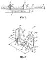
- FIG. 1illustrates a circuit board 10 , with a bottom side power converter module 12 , coupled thereto by soldering 13 .
- the hand solderingis very difficult due to the large mass presented by the leads 14 of the power converter module 12 , as well as the extensive external and internal power planes that typically exist on the circuit board 10 .
- Special automated methods of solder attachmentare also available for bottom side power converter attachment, including robotic soldering and selective wave machines. However, these machines are not standard equipment items in board manufacturing shops and rework/repair facilities, are very high capital expense items, and still experience similar solder difficulties as manual soldering due to the large mass of leads and extensive power planes on the circuit board.
- the power converter modulehas internal solder connections that are at risk of solder re-reflow, and subsequent damage, when the external leads 14 are manually soldered to the circuit board.
- the risk of internal damagerequires each power converter module manufacturer to stipulate strict manual solder parameters (e.g., temperature and solder iron dwell time applied to each lead). Such parameters are extremely difficult to adhere to.
- a socket interconnect approachis desirable as a means of coupling the power converter module to and from the circuit board assembly without the need for manual or special automated soldering.
- a further complicationis that many commercially available off-the-shelf power sockets that have a discrete design are not suitable for the vacuum pickup that is used in automated pick-and-place techniques using standard surface-mount assembly equipment. Therefore, the power sockets require either special assembly processes or hand placement.
- a special assembly processrequires special automated insertion equipment, such as odd-form placement equipment, with grippers. This results in additional capital costs.
- Hand placementon the other hand, is inferior in both cost and quality, as compared to viable automated placement alternatives.
- Non-discrete power socketswhich may include a “ganged” design of discrete sockets, utilize a plastic, molded carrier to simultaneously insert all sockets.
- the ganged designpermits the use of standard automated surface-mounting equipment.
- such socketsare still a top entry design. Therefore, they also require bottom side attachment and hand soldering, or an extra pass through the reflow oven, as noted above.
- this ganged approachis cost prohibitive for small to moderate volumes of different power converter module designs that have different pin arrangements. This is because hard tooling is required for the plastic carrier, and separate inventories are required for each different part type.
- An interconnection element for coupling a component with a circuit board having a top side and a bottom sideincludes a planar portion that is configured to be surface mounted on the top side of the circuit board.
- the planar portionoverlies an opening in the circuit board that extends between the top and bottom sides of the board.
- An openingis formed in the planar portion to coincide with the board opening.
- Opposing spring fingersare coupled to the planar portion and each spring finger has a support leg extending upwardly from the planar portion and a gripping leg extending downwardly toward the planar portion.
- the gripping legs of the opposing spring fingersare positioned on opposite sides of the opening in the planar portion and are configured to grip a component lead that extends in the board opening from the bottom side of the circuit board.
- the gripping leg of each spring fingerextends through the opening in the planar portion to extend into the board opening and capture the lead below the top side of the circuit board
- FIG. 1illustrates a prior art circuit board, with a power converter module that is hand soldered.
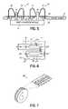
- FIG. 2is a perspective view of an interconnection element, in accordance with one embodiment of the invention.
- FIG. 3is a perspective view of an interconnection element, in accordance with an alternative embodiment of the invention.
- FIG. 4is a cut-away side view, in partial cross-section, illustrating use of the invention to connect a component with a circuit board.
- FIG. 4Ais a cut-away side view similar to FIG. 4 showing a pin positioned but not inserted.
- FIG. 5is a cut-away side view of a circuit board utilizing the present invention for coupling components thereto.
- FIG. 6is a top view of one embodiment of a topside solder pad or footprint pattern on a circuit board for implementing the present invention.
- FIG. 7is a perspective view of a tape-and-reel arrangement for implement the present invention with pick-and-place automated equipment.
- the present inventioncan address various drawbacks in the prior art as noted above, and provides an interconnection element or socket to couple a component to a circuit board. It provides a robust mechanical and electrical connection between a circuit board and one or more components or modules, such as a power converter module.
- the interconnection elementprovides both surface-mount technology (SMT) and through-hole attachment techniques, thus, providing a robust physical attachment as well as a robust electrical connection between the board and component.
- SMTsurface-mount technology
- through-hole attachment techniquesthus, providing a robust physical attachment as well as a robust electrical connection between the board and component.
- the interconnection elementsare discrete to adapt to various different component lead or pin arrangements, and do not require precise pin alignment with the interconnection element.
- the present inventionprovides a top side interconnection element that is configured to receive pins or leads from components inserted on the bottom side of a circuit board.
- the inventionis configured for automated surface-mount technology placement and fixation, and eliminates the need for hand soldering. Standard stencil printing methods can be used to provide repeatable application of solder volume on the circuit board before mounting.
- the present inventionis not only effectively and efficiently positioned and secured, but also may be readily extracted for re-work, repair or replacement of a component on the circuit board, such as a power converter module. Damage to both the component and the circuit board is minimized because of the elimination of a de-soldering and re-soldering process.
- FIGS. 2 and 3perspective views of various embodiments of the interconnection element of the invention are illustrated.
- Such an interconnection elementis also often referred to as a socket, and specifically might be considered the female version of the socket to receive the male version in the form of a pin or lead from an electrical component, such as a power converter module, that is plugged into the socket.
- an electrical componentsuch as a power converter module
- the interconnection element 20may be utilized for coupling a component, such as a power converter module 12 as illustrated in FIG. 1 , with a circuit board 10 .
- interconnection element 20is configured to be mounted on the top side 24 of a circuit board to then receive a lead or pin from the power converter module 12 mounted on the bottom side 26 of the circuit board 10 , as illustrated in FIGS. 4 and 5 , and discussed further herein below.
- the component attached to the circuit boardis indicated as a power converter module 12 , such as a power converter module coupled to the motherboard of an RF power amplifier.
- other circuit componentscan be physically and electrically connected with a circuit board utilizing the present invention. Therefore, the invention is not limited to use with just power modules.
- the present inventionprovides a suitable connection for the various power pins of a power converter module, which power connection requires a particularly robust electrical and physical connection.
- FIGS. 2 and 3illustrate alternative embodiments of the invention.
- FIG. 2is configured and dimensioned to receive a 0.040′′ diameter power converter module pin
- the embodiment of FIG. 3is configured and dimensioned to receive a similar-type pin, having a 0.081′′ diameter.
- Such dimensionsaddress a range of popular power converter module pins.
- the present inventionmay be readily scaled and/or dimensioned to address other lead or pin sizes.
- the embodiments of the interconnection elements 20are designated as 20 a in FIGS. 2 and 20 b for the embodiment in FIG. 3 .
- similar reference numeralswill be utilized to designate the common sections or portions for each element, as discussed herein.
- element 20 aincludes a planar portion 22 , which defines a base for the interconnection element 20 a .
- the planar portionis generally planar or flat and is, thus, configured to be surface-mounted on a side of a flat circuit board.
- the generally planar portiondoes not have to be exactly flat or planar for the purposes of the invention.
- the circuit board sides 24 , 26are designated as a top side 24 or a bottom side 26 , but the designation of top and bottom is generally relative.
- the top side 24 of the circuit board 10will be considered to contain the majority of the various surface-mounted electrical components of the circuit board, along with conductive traces and patterns for connecting those elements.
- the bottom side 26(see FIGS. 4 and 5 ) will be considered the side to receive the power converter module 12 .
- the interconnection element 20 ais surface-mounted on the top side 24 of the circuit board to overlie an opening 28 ( FIGS. 4 and 6 ) that is formed in the circuit board to extend between the top side 24 and the bottom side 26 of the board.
- the leads 14 of the power converter module 12extend through the opening 28 from the bottom side 26 to the top side 24 of the board.
- An opening 30is formed in the planar portion 22 , and coincides with the board opening 28 , when the planar portion is surface-mounted to overlie that opening 28 . In that way, lead 14 can extend up through the planar portion 22 of element 20 a.
- the interconnection element 20also includes opposing spring fingers 32 on opposite sides of the planar portion 22 .
- the spring fingers 32are essentially mirror images of each other, and thus will share common reference numerals for explanatory purposes.
- the opposing spring fingers 32are coupled to the planar portion 22 .
- the spring fingersare up-struck from a common metal blank utilizing known stamping and shaping metal techniques. Therefore, element 20 a is a unitary element in the disclosed embodiment.
- the spring fingers 32might also be coupled to the planar portion 22 in another suitable fashion.
- a suitable metal for forming interconnection elements 20is a beryllium copper that is tin-plated.
- the tin platingis utilized to match the tin plating generally found on pins of power converter modules.
- An underlying coating or finish of nickelmight be used for adhering the tin to the beryllium copper.
- the spring fingers 32are spring-biased toward each other, and are configured to grip a component lead 14 that extends into the board opening 28 , and through opening 30 of the interconnection element, as illustrated in FIGS. 4 and 5 .
- the spring fingers 32have ends that extend through the opening 30 in the planar portion 22 , and extend into the board opening 28 below the board top side 24 , in order to engage and grip the lead 14 below the top side 24 of circuit board 10 .
- the opposing spring fingers 32each include a support leg 34 that extends upwardly from planar portion 22 .
- the support leg and other sections of the spring fingersmay be struck from a single metal blank, such that the interconnection element is completely formed from a single piece of metal.
- the support legs 34extend upwardly from the planar portion 22 , and are each coupled to a respective gripping leg 36 that extends down toward the planar portion.
- a radiused section 38connects the support leg 34 with the gripping leg 36 , and the resiliency of the metal provides the spring action of the spring fingers 32 .
- each of the spring fingersis generally in the form of an inverted U-shaped or V-shaped element, extending upwardly from planar portion 22 .
- each gripping leg of the spring fingerseach define an axis 40 .
- the gripping legsare oriented so that the axes of those legs intersect each other at a point 42 that sits below the planar portion 22 and below the top side 24 of board 10 .
- Each gripping legalso extends through opening 30 to extend into the board opening 28 , as illustrated, to engage lead 14 below the top side 24 of the circuit board.
- each gripping leg of the spring fingerincludes a flared section 44 at the end of the spring finger that is angled on an axis away from the opposing gripping leg 36 .
- the ends of the opposing spring fingers, and particularly the ends of the opposing gripping legs 36form a flare area 46 to capture and engage the lead 14 as it is inserted up through the circuit board from the bottom side 26 to the top side 24 to engage the interconnection element 20 .
- the end flared sections 44 and the defined flare area 46which is formed thereby, accommodate various pin or lead alignment discrepancies when the module 12 is mounted.
- the interconnection element 20 a of the inventionis more forgiving, and does not require specific and highly-precise pin alignments with the interconnection element 20 a .
- the end flared sections 44capture the leading tip of the lead 14 , and guide it into proper engagement with the spring fingers 32 , so that the gripping force providing by the opposing spring fingers is sufficient to provide and maintain a good mechanical connection and excellent electrical connection, as well as to provide and maintain a robust electrical connection, for the purposes of efficient power and heat transfer.
- the interconnection element of the inventionprovides a certain amount of self-centering of the spring fingers over a misaligned pin.
- the flared sections 44 of the opposing gripping legsform an angle A (at rest) in the range of 67 to 134 degrees (See FIGS. 3 and 4 ). In one particular embodiment, the angle A is around 76°.
- the end flared sections 44 of the gripping leg that extend through opening 30 and into the board opening 28 to engage the lead below the top side of the circuit boardensure a proper and robust connection, and present a contact area that adapts to a wide variety of lead or pin protrusion lengths.
- some of the power converter module leads or pinsmay not significantly penetrate to a position well above the top side 24 of circuit board 10 , as illustrated in FIGS. 4 and 5 , due to varying circuit board thicknesses 10 or varying z-axis positions of power converter 12 with respect to circuit board 10 .
- Circuit board thicknessesfor example, may be in the range of 0.063-0.093 inches.
- the present inventionwith spring fingers that have ends extending below the effective bottom or base 22 of the interconnection element and into the opening 28 of the circuit board, provides suitable engagement of shorter power pin protrusion lengths for modules mounted on the bottom side of board 10 . Furthermore, the extension of the ends of the gripping legs through the center of the opening 30 and into or inside of the circuit board 10 provides for lead insertion at the center of spring fingers/gripping legs, and the center of the contact points 50 of the spring finger with the lead. (See FIG. 4A ). This further strengthens the electrical robustness of the connection. This critical feature of presenting the contact area that adapts to a wide variety of lead or pin protrusion lengths is inadequate and unsatisfactory in prior art power sockets.
- the present inventionprovides a discrete interconnection element or socket, which may be utilized to adapt to a variety of different components, and a wide variation of spacing for the individual leads or pins. Furthermore, the present invention is configured for close placement to adapt to closely-spaced leads on a component.
- the interconnection element 20 ahas a length L of around 8.6 mm, a width W of 2.79 mm, and an overall height H of around 5.9 mm.
- the larger embodiment illustrated in FIG. 3for a 0.081′′ pin, has a length L of around 9.4 mm, a width W of around 5.33 mm, and an overall height H of around 6.8 mm.
- the inventionmight be otherwise dimensioned to address a particular application or pin/lead size. The ability to address close placement and pin spacing, as addressed by the present invention, is inadequate and unsatisfactory in prior art power sockets.
- the gripping leg sections 36include a contact point or elbow 50 at the point where the flared sections 44 are angled away from each of the opposing gripping legs.
- the spacing S between those elbowsis dimensioned to provide suitable gripping of the power converter module lead 14 .
- FIG. 2which is configured to handle a power converter module lead, which is 0.040′′ in diameter, has a spacing S (at rest) of around 0.25 mm.
- the spacing S (at rest)might be around 0.76 mm, as it is configured to handle a power converter module lead having a diameter of approximately 0.081′′.
- the height H of the support leg 34 , the length L of the gripping leg 36 , the orientation of the angle of axis 40 , and the dimension of the radiused section 38might all be dimensioned and configured to achieve a particular spacing S and a particular gripping force on the power converter module leads 14 .
- a gripping force of approximately 1.65 lbs.is desired.
- the interconnection element 20provides a combination of attachment technologies, including both surface-mount technology and through-hole mounting technology.
- the interconnection element 20includes through-hole appendages 60 mounted at either end of the planar portion 22 .
- the through-hole appendages 60extend downwardly from the planar portion 22 , and are configured with tapered ends to consistently and properly engage a through-hole 62 formed in a circuit board 10 , as illustrated in FIG. 4 .
- Such appendagesmay be formed by down struck metal from the metal blank used to form element 20 .
- the through-hole appendages 60extend into the respective through-holes 62 , and thereby provide an additional mechanical and electrical connection for the interconnection element 20 .
- the dual mounting technology provided by the inventionprovides not only an additional electrical contact with the circuit board, but also provides an additional physical attachment point, which provides a robust physical attachment of the interconnection element to a circuit board.
- Through-hole mounting techniquesare generally more physically and electrically robust than surface-mounting technology.
- the present inventionprovides both mounting technologies together in a single package. This important and unique combination of features is not addressed in prior art power sockets.
- the through-hole appendages 60provide alignment features for the interconnection element 20 , so that it may be aligned properly on the circuit board. Not only is such alignment desirable for initial placement and solder attachment of the interconnection element, but also will be utilized for manual insertion when re-working and re-soldering the interconnection element if it has to be removed from the circuit board for some reason. This assured alignment accuracy of the interconnection element to the circuit board is critical to ensure a proper mechanical and electrical connection from the lead/pin to the interconnection element.
- FIG. 6illustrates a suitable solder pattern or pad configuration 70 for the interconnection element 20 of the invention.
- the solder patterns 70 on circuit board 10are illustrated in a generally rectangular shape, although other shapes may be utilized to coincide with the footprint of the interconnection element 20 and planar portion 22 .
- the opening 28 in the circuit board 10is illustrated and corresponds with a solder-free area in a solder pattern 70 .
- a solder-free areais provided at the through-holes 62 formed in the board.
- Solder pattern 70includes a large area to receive the planar portion or base 22 of the interconnection element 20 , and thus provides suitable surface-mounting of the interconnection element, according to known SMT techniques.
- the appendages 60are aligned in the respective through-holes 62 , and soldered into the through-holes.
- a stenciled print of solder pastemay be made according to suitable patterns 70 , as illustrated in FIG. 6 , for repeatable application of solder volume, to simultaneously mount the planar portion 22 and appendages 60 of the interconnection element.
- suitable patterns 70for repeatable application of solder volume
- manual or hand soldering of the power converter pinsmay be eliminated in order to eliminate all the drawbacks and possible damage to circuit components associated with such manual soldering techniques.
- Oven reflow of the solder pasteis utilized for repeatable, quality soldering attachment of the interconnection element.
- the elimination of difficult manual solderingremoves the need to have special training and operator “certification” for the assembly process.
- the risk of internal damage to the power converter modules' internal connectionis also eliminated as an issue because the leads 14 are not subject to a solder iron.
- the present inventionalso provides a very effective and efficient means for extracting the power converter module for re-work/repair, thus eliminating the risk of circuit board damage (especially for lead-free solder alloys) that is present when de-soldering and re-soldering the power converter module leads.
- the power converter modulemay be simply pulled off of the board, with the leads or pins being pulled from their respective interconnection elements on the opposite side of the board.
- suitable solder pad pattern 70might be dimensioned and configured for the specific dimensions of the interconnection element.
- a solder pad configuration to utilize the interconnection element 20 amight have a width W as shown of around 3 mm, and a length L as shown of around 9.3 mm.
- a solder pattern with a width W of approximately 5.6 mm, and a length L of approximately 9.6 mmmight be utilized.
- the present inventionis also suitable for utilization in automated manufacturing.
- the tops of the spring fingersare suitable for vacuum pickup and placement for use with automated pick-and-place using standard surface-mounted assembly equipment. This is because the interconnection element of the invention is positioned on a top side of the circuit board, rather than on the bottom side, as would be necessary with prior art power sockets. Without the stringent positional tolerance requirements that are required by existing power sockets, utilization of the present invention allows for automated insertion, and eliminates the need for manual placement of the interconnection elements. Referring to FIG. 7 the present invention may, thus, be utilized in a tape-and-reel packaging 80 , as shown for use with automated SMT-mounting technology.
Landscapes
- Engineering & Computer Science (AREA)
- Manufacturing & Machinery (AREA)
- Microelectronics & Electronic Packaging (AREA)
- Structures For Mounting Electric Components On Printed Circuit Boards (AREA)
Abstract
Description
Claims (22)
Priority Applications (1)
| Application Number | Priority Date | Filing Date | Title |
|---|---|---|---|
| US12/113,285US7581965B1 (en) | 2008-05-01 | 2008-05-01 | Bottom entry interconnection element for connecting components to a circuit board |
Applications Claiming Priority (1)
| Application Number | Priority Date | Filing Date | Title |
|---|---|---|---|
| US12/113,285US7581965B1 (en) | 2008-05-01 | 2008-05-01 | Bottom entry interconnection element for connecting components to a circuit board |
Publications (1)
| Publication Number | Publication Date |
|---|---|
| US7581965B1true US7581965B1 (en) | 2009-09-01 |
Family
ID=41009146
Family Applications (1)
| Application Number | Title | Priority Date | Filing Date |
|---|---|---|---|
| US12/113,285ActiveUS7581965B1 (en) | 2008-05-01 | 2008-05-01 | Bottom entry interconnection element for connecting components to a circuit board |
Country Status (1)
| Country | Link |
|---|---|
| US (1) | US7581965B1 (en) |
Cited By (38)
| Publication number | Priority date | Publication date | Assignee | Title |
|---|---|---|---|---|
| US20090140572A1 (en)* | 2007-12-04 | 2009-06-04 | Mando Corporation | Pressure sensor |
| US20090278762A1 (en)* | 2008-05-09 | 2009-11-12 | Viasat, Inc. | Antenna Modular Sub-array Super Component |
| US20100221930A1 (en)* | 2007-10-02 | 2010-09-02 | Osram Gesellschaft Mit Beschraenkter Haftung | Plug device, plug connector, and method for producing the plug connector |
| US20110009013A1 (en)* | 2009-07-10 | 2011-01-13 | Chi Mei Communication Systems, Inc. | Elastic sheet structure |
| US8123572B2 (en)* | 2010-04-02 | 2012-02-28 | Tyco Electronics Corporation | Electrical components having a contact configured to engage a via of a circuit board |
| DE102012101449A1 (en)* | 2012-02-23 | 2013-08-29 | Phoenix Contact Gmbh & Co. Kg | Printed circuit board terminal of inverter, has contact elements that are clamped against conductor in terminal portion, and are soldered at top surface or bottom surface of circuit board |
| US20130285232A1 (en)* | 2012-04-27 | 2013-10-31 | Samsung Electro-Mechanics Co., Ltd. | Semiconductor package module |
| US8721376B1 (en)* | 2012-11-01 | 2014-05-13 | Avx Corporation | Single element wire to board connector |
| US20140338160A1 (en)* | 2013-05-17 | 2014-11-20 | Hon Hai Precision Industry Co., Ltd. | Spring clip assembly |
| EP2814116A1 (en)* | 2013-06-12 | 2014-12-17 | Valeo Vision | Electrical connection clip for printed circuit board with illumination LED |
| EP2843766A1 (en)* | 2013-09-02 | 2015-03-04 | Legrand France | Electrical device including an electric circuit printed on a substrate and an electric connection terminal |
| WO2015032788A1 (en)* | 2013-09-09 | 2015-03-12 | Phoenix Contact Gmbh & Co. Kg | Clamping spring |
| CN104813543A (en)* | 2012-10-25 | 2015-07-29 | 法雷奥电机控制系统公司 | Electrical contacts and electronic circuits |
| US9136641B2 (en) | 2012-11-01 | 2015-09-15 | Avx Corporation | Single element wire to board connector |
| RU2571003C1 (en)* | 2014-06-03 | 2015-12-20 | Дмитрий Анатольевич Семаков | Light-emitting diode module |
| US20160069555A1 (en)* | 2014-03-19 | 2016-03-10 | Bingshui Chen | Head-Hoop Type Connector and LED Lamp Using Same |
| US20160254627A1 (en)* | 2015-02-27 | 2016-09-01 | Norman R. Byrne | Electrical contact receptacle for bus bars and blade terminals |
| US20160315403A1 (en)* | 2015-04-27 | 2016-10-27 | Foxconn Interconnect Technology Limited | Low profile connector and assembly of the same |
| US20170276339A1 (en)* | 2015-08-11 | 2017-09-28 | Xiamen Eco Lighting Co. Ltd. | Electronic connector device |
| US20170276338A1 (en)* | 2015-08-10 | 2017-09-28 | Xiamen Eco Lighting Co. Ltd. | Electrical connector device of led light |
| US10033253B2 (en)* | 2014-12-22 | 2018-07-24 | Denso Corporation | Drive device |
| EP3422475A1 (en)* | 2017-06-29 | 2019-01-02 | Laird Technologies, Inc. | Vehicular antenna assemblies |
| US10218107B2 (en) | 2014-10-06 | 2019-02-26 | Avx Corporation | Caged poke home contact |
| US20190140370A1 (en)* | 2017-11-07 | 2019-05-09 | Zierick Manufacturing Corporation | Smt box receptacle with release levers |
| DE102014108965B4 (en) | 2013-06-26 | 2019-05-23 | Avx Corporation | Single element electrical connector and electrical device for connecting a wire to a printed circuit board |
| US10320096B2 (en) | 2017-06-01 | 2019-06-11 | Avx Corporation | Flexing poke home contact |
| US20190223297A1 (en)* | 2018-01-12 | 2019-07-18 | Xiamen Ghgm Industrial Trade Co., Ltd. | All-metal surface mount female connector and connecting structure using the same |
| US10605447B2 (en)* | 2018-04-24 | 2020-03-31 | Xiamen Eco Lighting Co. Ltd. | LED filament bulb apparatus |
| US10707598B2 (en)* | 2018-01-23 | 2020-07-07 | Tyco Electronics (Shanghai) Co. Ltd. | Conductive terminal and connector assembly |
| US10770955B2 (en)* | 2016-03-02 | 2020-09-08 | Hitachi Automotive Systems, Ltd. | Connection terminal assembly and electromotive drive device using same |
| USD915299S1 (en)* | 2018-11-15 | 2021-04-06 | Dinkle Enterprise Co., Ltd. | Wiring terminal |
| US20220037816A1 (en)* | 2020-07-28 | 2022-02-03 | Japan Aviation Electronics Industry, Limited | Solderable component and board assembly |
| US20220094118A1 (en)* | 2020-09-23 | 2022-03-24 | Group Dekko, Inc. | Water-in-fuel sensor and method of assembly thereof |
| DE102020214324A1 (en) | 2020-11-13 | 2022-05-19 | Brose Fahrzeugteile SE & Co. Kommanditgesellschaft, Würzburg | Electronics unit for an electric refrigerant drive |
| US11374366B2 (en) | 2020-06-19 | 2022-06-28 | Lear Corporation | System and method for providing an electrical ground connection for a circuit assembly |
| US11646514B2 (en) | 2020-08-10 | 2023-05-09 | Lear Corporation | Surface mount technology terminal header and method for providing an electrical connection to a printed circuit board |
| DE102022104592B3 (en) | 2022-02-25 | 2023-06-15 | Cherry Europe Gmbh | Connection device for electrically connecting a functional module to a circuit substrate for a keyboard, keyboard and method for producing a keyboard |
| US11706867B2 (en) | 2021-01-27 | 2023-07-18 | Lear Corporation | System and method for providing an electrical ground connection for a circuit assembly |
Citations (40)
| Publication number | Priority date | Publication date | Assignee | Title |
|---|---|---|---|---|
| US2869040A (en) | 1954-01-11 | 1959-01-13 | Sylvania Electric Prod | Solder-dipped stamped wiring |
| US2968780A (en) | 1959-01-20 | 1961-01-17 | Edwards Company Inc | Solderless connector |
| US2972727A (en) | 1958-07-01 | 1961-02-21 | United Carr Fastener Corp | Printed circuit assembly |
| US2973499A (en) | 1958-03-12 | 1961-02-28 | Amp Inc | Socket connector means for circuit board |
| US3008112A (en) | 1958-03-12 | 1961-11-07 | Amp Inc | Connector means for circuit board |
| US3696323A (en) | 1970-02-27 | 1972-10-03 | Amp Inc | Dip header |
| US3718895A (en) | 1971-02-01 | 1973-02-27 | Amp Inc | Connecting device for printed circuit board |
| US3824557A (en) | 1971-08-24 | 1974-07-16 | Interdyne Co | Electrical contact |
| US3884544A (en) | 1973-10-17 | 1975-05-20 | Amp Inc | Connector for circuit boards or the like |
| US3902776A (en) | 1973-12-28 | 1975-09-02 | Amp Inc | Free standing mother-daughter printed circuit board contact arrangement |
| US3915544A (en)* | 1974-11-05 | 1975-10-28 | Gen Motors Corp | Electrical terminal |
| US4076355A (en) | 1975-03-17 | 1978-02-28 | Amp Incorporated | Connector for connecting together opposite sides of a printed circuit board |
| US4083623A (en) | 1977-02-18 | 1978-04-11 | Amp Incorporated | Mini spring socket with plastic base |
| US4089575A (en) | 1976-09-27 | 1978-05-16 | Amp Incorporated | Connector for connecting a circuit element to the surface of a substrate |
| US4274696A (en) | 1979-11-23 | 1981-06-23 | Amp Incorporated | Electrical connecting device for wiring systems |
| US4379611A (en) | 1980-11-03 | 1983-04-12 | Hughes Aircraft Company | Connector with low force socket contact having an integral hood |
| US4422128A (en) | 1981-08-06 | 1983-12-20 | General Motors Corporation | Push-on terminal clip and assembly |
| US4550959A (en) | 1983-04-13 | 1985-11-05 | Amp Incorporated | Surface mountable coefficient of expansion matching connector |
| US4575167A (en) | 1984-04-02 | 1986-03-11 | Minter Jerry B | Electrical connector for printed circuit boards and the like |
| US4645278A (en) | 1985-09-09 | 1987-02-24 | Texas Instruments Incorporated | Circuit panel connector, panel system using the connector, and method for making the panel system |
| US4682829A (en) | 1985-06-13 | 1987-07-28 | Amp Incorporated | Surface mount socket for dual in-line package |
| US4797110A (en) | 1986-09-08 | 1989-01-10 | General Motors Corporation | Printed circuit board with integral electrical connector and method for making it using wave soldering |
| US4992057A (en) | 1989-04-13 | 1991-02-12 | U.S. Philips Corporation | Device comprising a carrier with holes for receiving pins |
| US5042146A (en) | 1990-02-06 | 1991-08-27 | Watson Troy M | Method and apparatus of making an electrical interconnection on a circuit board |
| US5064379A (en)* | 1989-10-30 | 1991-11-12 | Amp Incorporated | Printed circuit board contact |
| US5131853A (en) | 1991-08-12 | 1992-07-21 | Delco Electronics Corporation | Low profile receptacle terminal for soldering to a circuit board |
| US5154621A (en) | 1991-07-29 | 1992-10-13 | Zierick Manufacturing Corporation | Printed circuit board contact system |
| US5433616A (en) | 1991-07-16 | 1995-07-18 | E.I. Du Pont De Nemours And Company | Low profile surface-mounted connector having curved cantilevered spring contacts |
| US5709574A (en) | 1996-08-30 | 1998-01-20 | Autosplice Systems Inc. | Surface-mountable socket connector |
| US6051781A (en) | 1997-09-24 | 2000-04-18 | Autosplice, Inc. | Surface mount electromagnetic frequency interference shield clip |
| US6079990A (en) | 1999-02-02 | 2000-06-27 | Molex Incorporated | Terminal-receiving socket for mounting on a circuit board |
| US6089880A (en)* | 1996-11-28 | 2000-07-18 | Denso Corporation | Electric connector arrangement |
| US6315580B1 (en) | 1999-06-04 | 2001-11-13 | Astec International Limited | PCB connector module for plug-in circuit breakers and fuses |
| US6319025B1 (en) | 1997-07-17 | 2001-11-20 | Nec Corporation | Surface installing type connector |
| US6319024B1 (en) | 1999-06-09 | 2001-11-20 | Avaya Technology Corp. | Strain relief mechanism for a plug-in protector panel |
| US6659812B2 (en) | 2002-04-19 | 2003-12-09 | Tektronix, Inc. | Surface mount probe point socket and system |
| US6659784B1 (en) | 1998-12-02 | 2003-12-09 | Framatome Connectors Inc. | Connector with switching device |
| US6750396B2 (en) | 2000-12-15 | 2004-06-15 | Di/Dt, Inc. | I-channel surface-mount connector |
| US7207811B2 (en) | 2003-12-18 | 2007-04-24 | Weco Electrical Connectors Inc. | Electrical connector |
| FR2898734A1 (en) | 2006-03-17 | 2007-09-21 | Abb Entrelec Soc Par Actions S | Female contact type surface mount connector for connecting e.g. tab, has elastic tabs forming locking space for male contact type conductive element, and opening arranged for passage of element, where space has divergent side edges |
- 2008
- 2008-05-01USUS12/113,285patent/US7581965B1/enactiveActive
Patent Citations (40)
| Publication number | Priority date | Publication date | Assignee | Title |
|---|---|---|---|---|
| US2869040A (en) | 1954-01-11 | 1959-01-13 | Sylvania Electric Prod | Solder-dipped stamped wiring |
| US2973499A (en) | 1958-03-12 | 1961-02-28 | Amp Inc | Socket connector means for circuit board |
| US3008112A (en) | 1958-03-12 | 1961-11-07 | Amp Inc | Connector means for circuit board |
| US2972727A (en) | 1958-07-01 | 1961-02-21 | United Carr Fastener Corp | Printed circuit assembly |
| US2968780A (en) | 1959-01-20 | 1961-01-17 | Edwards Company Inc | Solderless connector |
| US3696323A (en) | 1970-02-27 | 1972-10-03 | Amp Inc | Dip header |
| US3718895A (en) | 1971-02-01 | 1973-02-27 | Amp Inc | Connecting device for printed circuit board |
| US3824557A (en) | 1971-08-24 | 1974-07-16 | Interdyne Co | Electrical contact |
| US3884544A (en) | 1973-10-17 | 1975-05-20 | Amp Inc | Connector for circuit boards or the like |
| US3902776A (en) | 1973-12-28 | 1975-09-02 | Amp Inc | Free standing mother-daughter printed circuit board contact arrangement |
| US3915544A (en)* | 1974-11-05 | 1975-10-28 | Gen Motors Corp | Electrical terminal |
| US4076355A (en) | 1975-03-17 | 1978-02-28 | Amp Incorporated | Connector for connecting together opposite sides of a printed circuit board |
| US4089575A (en) | 1976-09-27 | 1978-05-16 | Amp Incorporated | Connector for connecting a circuit element to the surface of a substrate |
| US4083623A (en) | 1977-02-18 | 1978-04-11 | Amp Incorporated | Mini spring socket with plastic base |
| US4274696A (en) | 1979-11-23 | 1981-06-23 | Amp Incorporated | Electrical connecting device for wiring systems |
| US4379611A (en) | 1980-11-03 | 1983-04-12 | Hughes Aircraft Company | Connector with low force socket contact having an integral hood |
| US4422128A (en) | 1981-08-06 | 1983-12-20 | General Motors Corporation | Push-on terminal clip and assembly |
| US4550959A (en) | 1983-04-13 | 1985-11-05 | Amp Incorporated | Surface mountable coefficient of expansion matching connector |
| US4575167A (en) | 1984-04-02 | 1986-03-11 | Minter Jerry B | Electrical connector for printed circuit boards and the like |
| US4682829A (en) | 1985-06-13 | 1987-07-28 | Amp Incorporated | Surface mount socket for dual in-line package |
| US4645278A (en) | 1985-09-09 | 1987-02-24 | Texas Instruments Incorporated | Circuit panel connector, panel system using the connector, and method for making the panel system |
| US4797110A (en) | 1986-09-08 | 1989-01-10 | General Motors Corporation | Printed circuit board with integral electrical connector and method for making it using wave soldering |
| US4992057A (en) | 1989-04-13 | 1991-02-12 | U.S. Philips Corporation | Device comprising a carrier with holes for receiving pins |
| US5064379A (en)* | 1989-10-30 | 1991-11-12 | Amp Incorporated | Printed circuit board contact |
| US5042146A (en) | 1990-02-06 | 1991-08-27 | Watson Troy M | Method and apparatus of making an electrical interconnection on a circuit board |
| US5433616A (en) | 1991-07-16 | 1995-07-18 | E.I. Du Pont De Nemours And Company | Low profile surface-mounted connector having curved cantilevered spring contacts |
| US5154621A (en) | 1991-07-29 | 1992-10-13 | Zierick Manufacturing Corporation | Printed circuit board contact system |
| US5131853A (en) | 1991-08-12 | 1992-07-21 | Delco Electronics Corporation | Low profile receptacle terminal for soldering to a circuit board |
| US5709574A (en) | 1996-08-30 | 1998-01-20 | Autosplice Systems Inc. | Surface-mountable socket connector |
| US6089880A (en)* | 1996-11-28 | 2000-07-18 | Denso Corporation | Electric connector arrangement |
| US6319025B1 (en) | 1997-07-17 | 2001-11-20 | Nec Corporation | Surface installing type connector |
| US6051781A (en) | 1997-09-24 | 2000-04-18 | Autosplice, Inc. | Surface mount electromagnetic frequency interference shield clip |
| US6659784B1 (en) | 1998-12-02 | 2003-12-09 | Framatome Connectors Inc. | Connector with switching device |
| US6079990A (en) | 1999-02-02 | 2000-06-27 | Molex Incorporated | Terminal-receiving socket for mounting on a circuit board |
| US6315580B1 (en) | 1999-06-04 | 2001-11-13 | Astec International Limited | PCB connector module for plug-in circuit breakers and fuses |
| US6319024B1 (en) | 1999-06-09 | 2001-11-20 | Avaya Technology Corp. | Strain relief mechanism for a plug-in protector panel |
| US6750396B2 (en) | 2000-12-15 | 2004-06-15 | Di/Dt, Inc. | I-channel surface-mount connector |
| US6659812B2 (en) | 2002-04-19 | 2003-12-09 | Tektronix, Inc. | Surface mount probe point socket and system |
| US7207811B2 (en) | 2003-12-18 | 2007-04-24 | Weco Electrical Connectors Inc. | Electrical connector |
| FR2898734A1 (en) | 2006-03-17 | 2007-09-21 | Abb Entrelec Soc Par Actions S | Female contact type surface mount connector for connecting e.g. tab, has elastic tabs forming locking space for male contact type conductive element, and opening arranged for passage of element, where space has divergent side edges |
Cited By (65)
| Publication number | Priority date | Publication date | Assignee | Title |
|---|---|---|---|---|
| US20100221930A1 (en)* | 2007-10-02 | 2010-09-02 | Osram Gesellschaft Mit Beschraenkter Haftung | Plug device, plug connector, and method for producing the plug connector |
| US20090140572A1 (en)* | 2007-12-04 | 2009-06-04 | Mando Corporation | Pressure sensor |
| US20090278762A1 (en)* | 2008-05-09 | 2009-11-12 | Viasat, Inc. | Antenna Modular Sub-array Super Component |
| US20110009013A1 (en)* | 2009-07-10 | 2011-01-13 | Chi Mei Communication Systems, Inc. | Elastic sheet structure |
| US7972186B2 (en)* | 2009-07-10 | 2011-07-05 | Chi Mei Communication Systems, Inc. | Elastic sheet structure |
| US8123572B2 (en)* | 2010-04-02 | 2012-02-28 | Tyco Electronics Corporation | Electrical components having a contact configured to engage a via of a circuit board |
| DE102012101449B4 (en) | 2012-02-23 | 2018-05-03 | Phoenix Contact Gmbh & Co. Kg | Printed circuit board connection, method for forming a printed circuit board connection and inverter comprising a printed circuit board connection |
| DE102012101449A1 (en)* | 2012-02-23 | 2013-08-29 | Phoenix Contact Gmbh & Co. Kg | Printed circuit board terminal of inverter, has contact elements that are clamped against conductor in terminal portion, and are soldered at top surface or bottom surface of circuit board |
| US20130285232A1 (en)* | 2012-04-27 | 2013-10-31 | Samsung Electro-Mechanics Co., Ltd. | Semiconductor package module |
| CN104813543B (en)* | 2012-10-25 | 2018-11-06 | 法雷奥电机控制系统公司 | Electric contact piece and electronic circuit |
| US9705214B2 (en)* | 2012-10-25 | 2017-07-11 | Valeo Systemes De Controle Moteur | Electrical contact and electronic circuit |
| US20150288086A1 (en)* | 2012-10-25 | 2015-10-08 | Valeo Systemes De Controle Moteur | Electrical Contact and Electronic Circuit |
| CN104813543A (en)* | 2012-10-25 | 2015-07-29 | 法雷奥电机控制系统公司 | Electrical contacts and electronic circuits |
| US9166325B2 (en) | 2012-11-01 | 2015-10-20 | Avx Corporation | Single element wire to board connector |
| US10116067B2 (en) | 2012-11-01 | 2018-10-30 | Avx Corporation | Single element wire to board connector |
| US9466893B2 (en) | 2012-11-01 | 2016-10-11 | Avx Corporation | Single element wire to board connector |
| US9136641B2 (en) | 2012-11-01 | 2015-09-15 | Avx Corporation | Single element wire to board connector |
| US9768527B2 (en) | 2012-11-01 | 2017-09-19 | Avx Corporation | Single element wire to board connector |
| US8721376B1 (en)* | 2012-11-01 | 2014-05-13 | Avx Corporation | Single element wire to board connector |
| US20140338160A1 (en)* | 2013-05-17 | 2014-11-20 | Hon Hai Precision Industry Co., Ltd. | Spring clip assembly |
| FR3007216A1 (en)* | 2013-06-12 | 2014-12-19 | Valeo Vision | ELECTRICAL CONNECTION CLAMP FOR PLATINUM WITH LIGHTING LED |
| EP2814116A1 (en)* | 2013-06-12 | 2014-12-17 | Valeo Vision | Electrical connection clip for printed circuit board with illumination LED |
| DE102014108965B4 (en) | 2013-06-26 | 2019-05-23 | Avx Corporation | Single element electrical connector and electrical device for connecting a wire to a printed circuit board |
| CN104425943B (en)* | 2013-09-02 | 2018-02-06 | 勒格朗法国公司 | Include the electric device of the printed circuit on electric connection terminal and support plate |
| EP2843766A1 (en)* | 2013-09-02 | 2015-03-04 | Legrand France | Electrical device including an electric circuit printed on a substrate and an electric connection terminal |
| FR3010240A1 (en)* | 2013-09-02 | 2015-03-06 | Legrand France | ELECTRICAL DEVICE COMPRISING AN ELECTRIC CIRCUIT PRINTED ON A SUPPORT PLATE AND AN ELECTRICAL CONNECTION TERMINAL |
| CN104425943A (en)* | 2013-09-02 | 2015-03-18 | 勒格朗法国公司 | Electrical device including printed circuit printed on a substrate and an electric connection terminal |
| WO2015032788A1 (en)* | 2013-09-09 | 2015-03-12 | Phoenix Contact Gmbh & Co. Kg | Clamping spring |
| US9711876B2 (en) | 2013-09-09 | 2017-07-18 | Phoenix Contact Gmbh & Co. Kg | Clamping spring |
| US20160069555A1 (en)* | 2014-03-19 | 2016-03-10 | Bingshui Chen | Head-Hoop Type Connector and LED Lamp Using Same |
| RU2571003C1 (en)* | 2014-06-03 | 2015-12-20 | Дмитрий Анатольевич Семаков | Light-emitting diode module |
| US10218107B2 (en) | 2014-10-06 | 2019-02-26 | Avx Corporation | Caged poke home contact |
| US10033253B2 (en)* | 2014-12-22 | 2018-07-24 | Denso Corporation | Drive device |
| US9711921B2 (en)* | 2015-02-27 | 2017-07-18 | Norman R. Byrne | Electrical contact receptacle for bus bars and blade terminals |
| US20160254627A1 (en)* | 2015-02-27 | 2016-09-01 | Norman R. Byrne | Electrical contact receptacle for bus bars and blade terminals |
| US9825382B2 (en)* | 2015-04-27 | 2017-11-21 | Foxconn Interconnect Technology Limited | Low profile connector and assembly of the same |
| US20160315403A1 (en)* | 2015-04-27 | 2016-10-27 | Foxconn Interconnect Technology Limited | Low profile connector and assembly of the same |
| US20170276338A1 (en)* | 2015-08-10 | 2017-09-28 | Xiamen Eco Lighting Co. Ltd. | Electrical connector device of led light |
| US10060612B2 (en)* | 2015-08-10 | 2018-08-28 | Xiamen Eco Lighting Co. Ltd. | Electrical connector device of LED light |
| US20170276339A1 (en)* | 2015-08-11 | 2017-09-28 | Xiamen Eco Lighting Co. Ltd. | Electronic connector device |
| US10066822B2 (en)* | 2015-08-11 | 2018-09-04 | Xiamen Eco Lighting Co. Ltd. | Electronic connector device |
| EP3260774B1 (en)* | 2015-08-11 | 2020-05-13 | Leedarson Lighting Co., Ltd. | Electrical connection member |
| US10770955B2 (en)* | 2016-03-02 | 2020-09-08 | Hitachi Automotive Systems, Ltd. | Connection terminal assembly and electromotive drive device using same |
| US10320096B2 (en) | 2017-06-01 | 2019-06-11 | Avx Corporation | Flexing poke home contact |
| US10566711B2 (en) | 2017-06-01 | 2020-02-18 | Avx Corporation | Flexing poke home contact |
| CN109216881A (en)* | 2017-06-29 | 2019-01-15 | 莱尔德无线技术(上海)有限公司 | Car antenna component |
| EP3422475A1 (en)* | 2017-06-29 | 2019-01-02 | Laird Technologies, Inc. | Vehicular antenna assemblies |
| US10862187B2 (en) | 2017-06-29 | 2020-12-08 | Laird Technologies, Inc. | Vehicular antenna assemblies |
| US20190140370A1 (en)* | 2017-11-07 | 2019-05-09 | Zierick Manufacturing Corporation | Smt box receptacle with release levers |
| US10594052B2 (en)* | 2017-11-07 | 2020-03-17 | Zierick Manufacturing Corporation | SMT box receptacle with release levers |
| US20190223297A1 (en)* | 2018-01-12 | 2019-07-18 | Xiamen Ghgm Industrial Trade Co., Ltd. | All-metal surface mount female connector and connecting structure using the same |
| US10707598B2 (en)* | 2018-01-23 | 2020-07-07 | Tyco Electronics (Shanghai) Co. Ltd. | Conductive terminal and connector assembly |
| US10605447B2 (en)* | 2018-04-24 | 2020-03-31 | Xiamen Eco Lighting Co. Ltd. | LED filament bulb apparatus |
| US10801712B2 (en)* | 2018-04-24 | 2020-10-13 | Xiamen Eco Lighting Co. Ltd. | LED lighting apparatus |
| USD915299S1 (en)* | 2018-11-15 | 2021-04-06 | Dinkle Enterprise Co., Ltd. | Wiring terminal |
| US11374366B2 (en) | 2020-06-19 | 2022-06-28 | Lear Corporation | System and method for providing an electrical ground connection for a circuit assembly |
| US20220037816A1 (en)* | 2020-07-28 | 2022-02-03 | Japan Aviation Electronics Industry, Limited | Solderable component and board assembly |
| US11764502B2 (en)* | 2020-07-28 | 2023-09-19 | Japan Aviation Electronics Industry, Limited | Solderable component and board assembly |
| US11646514B2 (en) | 2020-08-10 | 2023-05-09 | Lear Corporation | Surface mount technology terminal header and method for providing an electrical connection to a printed circuit board |
| US20220094118A1 (en)* | 2020-09-23 | 2022-03-24 | Group Dekko, Inc. | Water-in-fuel sensor and method of assembly thereof |
| US11705677B2 (en)* | 2020-09-23 | 2023-07-18 | Group Dekko, Inc. | Water-in-fuel sensor and method of assembly thereof |
| DE102020214324A1 (en) | 2020-11-13 | 2022-05-19 | Brose Fahrzeugteile SE & Co. Kommanditgesellschaft, Würzburg | Electronics unit for an electric refrigerant drive |
| US11706867B2 (en) | 2021-01-27 | 2023-07-18 | Lear Corporation | System and method for providing an electrical ground connection for a circuit assembly |
| DE102022104592B3 (en) | 2022-02-25 | 2023-06-15 | Cherry Europe Gmbh | Connection device for electrically connecting a functional module to a circuit substrate for a keyboard, keyboard and method for producing a keyboard |
| US20230275371A1 (en)* | 2022-02-25 | 2023-08-31 | Cherry Europe Gmbh | Connector device for electrically connecting a functional module to a circuit substrate for a keyboard, keyboard and keyboard and method for producing a keyboard |
Similar Documents
| Publication | Publication Date | Title |
|---|---|---|
| US7581965B1 (en) | Bottom entry interconnection element for connecting components to a circuit board | |
| JP2582040B2 (en) | Method and apparatus for mounting a header assembly of an electrical connector to a mounting surface of an electrical device | |
| KR101024451B1 (en) | Interconnection pin/socket components for electrically connecting two circuit boards and method for mounting said components in a circuit board | |
| EP2472677B1 (en) | Circuit board assembly, board device, and method for assembling a circuit board assembly | |
| JP2018174017A (en) | socket | |
| US7604491B1 (en) | Techniques for providing electrical and thermal conductivity between electrical components and printed circuit boards using sleeves defining substantially conical shapes | |
| EP2533367A1 (en) | Electrical contact and method of manufacture of electrical contact | |
| US20160359246A1 (en) | Pin attach converter | |
| US7025640B2 (en) | Circuit board inter-connection system and method | |
| US6700800B2 (en) | Retainer for circuit board assembly and method for using the same | |
| US6830462B1 (en) | Electrical connector housing | |
| US20090284939A1 (en) | Alignment plate | |
| US8961200B2 (en) | Connector and solder sheet | |
| JPH0745346A (en) | Socket for chip part | |
| US6815614B1 (en) | Arrangement for co-planar vertical surface mounting of subassemblies on a mother board | |
| JP6445932B2 (en) | Bus bar and method of manufacturing bus bar | |
| US20020111080A1 (en) | Contact assembly, connector assembly utilizing same, and electronic assembly | |
| JP2023069208A (en) | Electronic component mounting method and electronic component | |
| CN220895896U (en) | Terminal structure | |
| US7145085B2 (en) | Enhanced connection arrangement for co-planar vertical surface mounting of subassemblies on a mother board | |
| EP2134146A1 (en) | Printed circuit board assembly and a method of assembling thereof | |
| CN222927791U (en) | Sinking type connector socket | |
| JPH0650286U (en) | Connector suction plate and connector having transport suction plate | |
| JPH03117711A (en) | Method of fitting surface-mounting connector on circuit board | |
| JPH0812789B2 (en) | Electrical component equipment |
Legal Events
| Date | Code | Title | Description |
|---|---|---|---|
| AS | Assignment | Owner name:COMMSCOPE, INC. OF NORTH CAROLINA, NORTH CAROLINA Free format text:ASSIGNMENT OF ASSIGNORS INTEREST;ASSIGNORS:UPASANI, SANJAY SUDHAKAR;KEBEDE, SEBSIBE;BROWN, RICHARD WILLIAM;AND OTHERS;REEL/FRAME:020884/0453;SIGNING DATES FROM 20080424 TO 20080429 | |
| AS | Assignment | Owner name:BANK OF AMERICA, N.A., AS ADMINISTRATIVE AGENT, CA Free format text:PARTIAL SECURITY AGREEMENT SUPPLEMENT;ASSIGNORS:COMMSCOPE, INC. OF NORTH CAROLINA;ANDREW CORPORATION;REEL/FRAME:021373/0437 Effective date:20080812 Owner name:BANK OF AMERICA, N.A., AS ADMINISTRATIVE AGENT,CAL Free format text:PARTIAL SECURITY AGREEMENT SUPPLEMENT;ASSIGNORS:COMMSCOPE, INC. OF NORTH CAROLINA;ANDREW CORPORATION;REEL/FRAME:021373/0437 Effective date:20080812 | |
| STCF | Information on status: patent grant | Free format text:PATENTED CASE | |
| AS | Assignment | Owner name:ALLEN TELECOM LLC, NORTH CAROLINA Free format text:PATENT RELEASE;ASSIGNOR:BANK OF AMERICA, N.A., AS ADMINISTRATIVE AGENT;REEL/FRAME:026039/0005 Effective date:20110114 Owner name:COMMSCOPE, INC. OF NORTH CAROLINA, NORTH CAROLINA Free format text:PATENT RELEASE;ASSIGNOR:BANK OF AMERICA, N.A., AS ADMINISTRATIVE AGENT;REEL/FRAME:026039/0005 Effective date:20110114 Owner name:ANDREW LLC (F/K/A ANDREW CORPORATION), NORTH CAROL Free format text:PATENT RELEASE;ASSIGNOR:BANK OF AMERICA, N.A., AS ADMINISTRATIVE AGENT;REEL/FRAME:026039/0005 Effective date:20110114 | |
| AS | Assignment | Owner name:JPMORGAN CHASE BANK, N.A., AS COLLATERAL AGENT, NE Free format text:SECURITY AGREEMENT;ASSIGNORS:ALLEN TELECOM LLC, A DELAWARE LLC;ANDREW LLC, A DELAWARE LLC;COMMSCOPE, INC. OF NORTH CAROLINA, A NORTH CAROLINA CORPORATION;REEL/FRAME:026276/0363 Effective date:20110114 | |
| AS | Assignment | Owner name:JPMORGAN CHASE BANK, N.A., AS COLLATERAL AGENT, NE Free format text:SECURITY AGREEMENT;ASSIGNORS:ALLEN TELECOM LLC, A DELAWARE LLC;ANDREW LLC, A DELAWARE LLC;COMMSCOPE, INC OF NORTH CAROLINA, A NORTH CAROLINA CORPORATION;REEL/FRAME:026272/0543 Effective date:20110114 | |
| FPAY | Fee payment | Year of fee payment:4 | |
| AS | Assignment | Owner name:WILMINGTON TRUST, NATIONAL ASSOCIATION, AS COLLATERAL AGENT, CONNECTICUT Free format text:SECURITY INTEREST;ASSIGNORS:ALLEN TELECOM LLC;COMMSCOPE TECHNOLOGIES LLC;COMMSCOPE, INC. OF NORTH CAROLINA;AND OTHERS;REEL/FRAME:036201/0283 Effective date:20150611 Owner name:WILMINGTON TRUST, NATIONAL ASSOCIATION, AS COLLATE Free format text:SECURITY INTEREST;ASSIGNORS:ALLEN TELECOM LLC;COMMSCOPE TECHNOLOGIES LLC;COMMSCOPE, INC. OF NORTH CAROLINA;AND OTHERS;REEL/FRAME:036201/0283 Effective date:20150611 | |
| FPAY | Fee payment | Year of fee payment:8 | |
| AS | Assignment | Owner name:REDWOOD SYSTEMS, INC., NORTH CAROLINA Free format text:RELEASE OF SECURITY INTEREST PATENTS (RELEASES RF 036201/0283);ASSIGNOR:WILMINGTON TRUST, NATIONAL ASSOCIATION;REEL/FRAME:042126/0434 Effective date:20170317 Owner name:ALLEN TELECOM LLC, NORTH CAROLINA Free format text:RELEASE OF SECURITY INTEREST PATENTS (RELEASES RF 036201/0283);ASSIGNOR:WILMINGTON TRUST, NATIONAL ASSOCIATION;REEL/FRAME:042126/0434 Effective date:20170317 Owner name:COMMSCOPE TECHNOLOGIES LLC, NORTH CAROLINA Free format text:RELEASE OF SECURITY INTEREST PATENTS (RELEASES RF 036201/0283);ASSIGNOR:WILMINGTON TRUST, NATIONAL ASSOCIATION;REEL/FRAME:042126/0434 Effective date:20170317 Owner name:COMMSCOPE, INC. OF NORTH CAROLINA, NORTH CAROLINA Free format text:RELEASE OF SECURITY INTEREST PATENTS (RELEASES RF 036201/0283);ASSIGNOR:WILMINGTON TRUST, NATIONAL ASSOCIATION;REEL/FRAME:042126/0434 Effective date:20170317 | |
| AS | Assignment | Owner name:ALLEN TELECOM LLC, ILLINOIS Free format text:RELEASE BY SECURED PARTY;ASSIGNOR:JPMORGAN CHASE BANK, N.A.;REEL/FRAME:048840/0001 Effective date:20190404 Owner name:ANDREW LLC, NORTH CAROLINA Free format text:RELEASE BY SECURED PARTY;ASSIGNOR:JPMORGAN CHASE BANK, N.A.;REEL/FRAME:048840/0001 Effective date:20190404 Owner name:REDWOOD SYSTEMS, INC., NORTH CAROLINA Free format text:RELEASE BY SECURED PARTY;ASSIGNOR:JPMORGAN CHASE BANK, N.A.;REEL/FRAME:048840/0001 Effective date:20190404 Owner name:COMMSCOPE, INC. OF NORTH CAROLINA, NORTH CAROLINA Free format text:RELEASE BY SECURED PARTY;ASSIGNOR:JPMORGAN CHASE BANK, N.A.;REEL/FRAME:048840/0001 Effective date:20190404 Owner name:COMMSCOPE TECHNOLOGIES LLC, NORTH CAROLINA Free format text:RELEASE BY SECURED PARTY;ASSIGNOR:JPMORGAN CHASE BANK, N.A.;REEL/FRAME:048840/0001 Effective date:20190404 Owner name:ANDREW LLC, NORTH CAROLINA Free format text:RELEASE BY SECURED PARTY;ASSIGNOR:JPMORGAN CHASE BANK, N.A.;REEL/FRAME:049260/0001 Effective date:20190404 Owner name:COMMSCOPE, INC. OF NORTH CAROLINA, NORTH CAROLINA Free format text:RELEASE BY SECURED PARTY;ASSIGNOR:JPMORGAN CHASE BANK, N.A.;REEL/FRAME:049260/0001 Effective date:20190404 Owner name:ALLEN TELECOM LLC, ILLINOIS Free format text:RELEASE BY SECURED PARTY;ASSIGNOR:JPMORGAN CHASE BANK, N.A.;REEL/FRAME:049260/0001 Effective date:20190404 Owner name:REDWOOD SYSTEMS, INC., NORTH CAROLINA Free format text:RELEASE BY SECURED PARTY;ASSIGNOR:JPMORGAN CHASE BANK, N.A.;REEL/FRAME:049260/0001 Effective date:20190404 Owner name:COMMSCOPE TECHNOLOGIES LLC, NORTH CAROLINA Free format text:RELEASE BY SECURED PARTY;ASSIGNOR:JPMORGAN CHASE BANK, N.A.;REEL/FRAME:049260/0001 Effective date:20190404 | |
| AS | Assignment | Owner name:WILMINGTON TRUST, NATIONAL ASSOCIATION, AS COLLATE Free format text:PATENT SECURITY AGREEMENT;ASSIGNOR:COMMSCOPE, INC. OF NORTH CAROLINA;REEL/FRAME:049678/0577 Effective date:20190404 Owner name:JPMORGAN CHASE BANK, N.A., NEW YORK Free format text:ABL SECURITY AGREEMENT;ASSIGNORS:COMMSCOPE, INC. OF NORTH CAROLINA;COMMSCOPE TECHNOLOGIES LLC;ARRIS ENTERPRISES LLC;AND OTHERS;REEL/FRAME:049892/0396 Effective date:20190404 Owner name:JPMORGAN CHASE BANK, N.A., NEW YORK Free format text:TERM LOAN SECURITY AGREEMENT;ASSIGNORS:COMMSCOPE, INC. OF NORTH CAROLINA;COMMSCOPE TECHNOLOGIES LLC;ARRIS ENTERPRISES LLC;AND OTHERS;REEL/FRAME:049905/0504 Effective date:20190404 Owner name:WILMINGTON TRUST, NATIONAL ASSOCIATION, AS COLLATERAL AGENT, CONNECTICUT Free format text:PATENT SECURITY AGREEMENT;ASSIGNOR:COMMSCOPE, INC. OF NORTH CAROLINA;REEL/FRAME:049678/0577 Effective date:20190404 | |
| FEPP | Fee payment procedure | Free format text:MAINTENANCE FEE REMINDER MAILED (ORIGINAL EVENT CODE: REM.); ENTITY STATUS OF PATENT OWNER: LARGE ENTITY | |
| FEPP | Fee payment procedure | Free format text:11.5 YR SURCHARGE- LATE PMT W/IN 6 MO, LARGE ENTITY (ORIGINAL EVENT CODE: M1556); ENTITY STATUS OF PATENT OWNER: LARGE ENTITY | |
| MAFP | Maintenance fee payment | Free format text:PAYMENT OF MAINTENANCE FEE, 12TH YEAR, LARGE ENTITY (ORIGINAL EVENT CODE: M1553); ENTITY STATUS OF PATENT OWNER: LARGE ENTITY Year of fee payment:12 | |
| AS | Assignment | Owner name:WILMINGTON TRUST, DELAWARE Free format text:SECURITY INTEREST;ASSIGNORS:ARRIS SOLUTIONS, INC.;ARRIS ENTERPRISES LLC;COMMSCOPE TECHNOLOGIES LLC;AND OTHERS;REEL/FRAME:060752/0001 Effective date:20211115 | |
| AS | Assignment | Owner name:COMMSCOPE, INC. OF NORTH CAROLINA, NORTH CAROLINA Free format text:PARTIAL RELEASE OF ABL SECURITY INTEREST;ASSIGNOR:JPMORGAN CHASE BANK, N.A.;REEL/FRAME:060649/0305 Effective date:20220712 Owner name:ARRIS ENTERPRISES LLC, NORTH CAROLINA Free format text:PARTIAL RELEASE OF ABL SECURITY INTEREST;ASSIGNOR:JPMORGAN CHASE BANK, N.A.;REEL/FRAME:060649/0305 Effective date:20220712 Owner name:COMMSCOPE TECHNOLOGIES LLC, NORTH CAROLINA Free format text:PARTIAL RELEASE OF ABL SECURITY INTEREST;ASSIGNOR:JPMORGAN CHASE BANK, N.A.;REEL/FRAME:060649/0305 Effective date:20220712 Owner name:COMMSCOPE, INC. OF NORTH CAROLINA, NORTH CAROLINA Free format text:PARTIAL RELEASE OF TERM LOAN SECURITY INTEREST;ASSIGNOR:JPMORGAN CHASE BANK, N.A.;REEL/FRAME:060649/0286 Effective date:20220712 Owner name:ARRIS ENTERPRISES LLC, NORTH CAROLINA Free format text:PARTIAL RELEASE OF TERM LOAN SECURITY INTEREST;ASSIGNOR:JPMORGAN CHASE BANK, N.A.;REEL/FRAME:060649/0286 Effective date:20220712 Owner name:COMMSCOPE TECHNOLOGIES LLC, NORTH CAROLINA Free format text:PARTIAL RELEASE OF TERM LOAN SECURITY INTEREST;ASSIGNOR:JPMORGAN CHASE BANK, N.A.;REEL/FRAME:060649/0286 Effective date:20220712 Owner name:BISON PATENT LICENSING, LLC, GEORGIA Free format text:ASSIGNMENT OF ASSIGNORS INTEREST;ASSIGNOR:COMMSCOPE, INC. OF NORTH CAROLINA;REEL/FRAME:060495/0033 Effective date:20220628 | |
| AS | Assignment | Owner name:COMMSCOPE, INC. OF NORTH CAROLINA, NORTH CAROLINA Free format text:PARTIAL TERMINATION AND RELEASE OF SECURITY INTEREST IN PATENTS;ASSIGNOR:WILMINGTON TRUST, NATIONAL ASSOCIATION, AS COLLATERAL AGENT;REEL/FRAME:060671/0324 Effective date:20220711 Owner name:ARRIS ENTERPRISES LLC, PENNSYLVANIA Free format text:PARTIAL TERMINATION AND RELEASE OF SECURITY INTEREST IN PATENTS;ASSIGNOR:WILMINGTON TRUST, NATIONAL ASSOCIATION, AS COLLATERAL AGENT;REEL/FRAME:060671/0324 Effective date:20220711 Owner name:COMMSCOPE TECHNOLOGIES LLC, NORTH CAROLINA Free format text:PARTIAL TERMINATION AND RELEASE OF SECURITY INTEREST IN PATENTS;ASSIGNOR:WILMINGTON TRUST, NATIONAL ASSOCIATION, AS COLLATERAL AGENT;REEL/FRAME:060671/0324 Effective date:20220711 | |
| AS | Assignment | Owner name:ARRIS ENTERPRISES LLC, GEORGIA Free format text:RELEASE BY SECURED PARTY;ASSIGNOR:WILMINGTON TRUST, NATIONAL ASSOCIATION;REEL/FRAME:063270/0220 Effective date:20221116 Owner name:COMMSCOPE, INC. OF NORTH CAROLINA, NORTH CAROLINA Free format text:RELEASE BY SECURED PARTY;ASSIGNOR:WILMINGTON TRUST, NATIONAL ASSOCIATION;REEL/FRAME:063270/0220 Effective date:20221116 Owner name:COMMSCOPE TECHNOLOGIES LLC, NORTH CAROLINA Free format text:RELEASE BY SECURED PARTY;ASSIGNOR:WILMINGTON TRUST, NATIONAL ASSOCIATION;REEL/FRAME:063270/0220 Effective date:20221116 | |
| AS | Assignment | Owner name:ARRIS ENTERPRISES LLC, GEORGIA Free format text:PARTIAL TERMINATION AND RELEASE OF SECURITY INTEREST IN PATENTS RECORDED AT R/F 060752/0001;ASSIGNOR:WILMINGTON TRUST;REEL/FRAME:063322/0209 Effective date:20221116 Owner name:COMMSCOPE, INC. OF NORTH CAROLINA, NORTH CAROLINA Free format text:PARTIAL TERMINATION AND RELEASE OF SECURITY INTEREST IN PATENTS RECORDED AT R/F 060752/0001;ASSIGNOR:WILMINGTON TRUST;REEL/FRAME:063322/0209 Effective date:20221116 Owner name:COMMSCOPE TECHNOLOGIES LLC, NORTH CAROLINA Free format text:PARTIAL TERMINATION AND RELEASE OF SECURITY INTEREST IN PATENTS RECORDED AT R/F 060752/0001;ASSIGNOR:WILMINGTON TRUST;REEL/FRAME:063322/0209 Effective date:20221116 | |
| AS | Assignment | Owner name:PROCOMM INTERNATIONAL PTE. LTD., SINGAPORE Free format text:ASSIGNMENT OF ASSIGNORS INTEREST;ASSIGNOR:BISON PATENT LICENSING, LLC;REEL/FRAME:064187/0897 Effective date:20230512 | |
| AS | Assignment | Owner name:RUCKUS WIRELESS, LLC (F/K/A RUCKUS WIRELESS, INC.), NORTH CAROLINA Free format text:RELEASE OF SECURITY INTEREST AT REEL/FRAME 049905/0504;ASSIGNOR:JPMORGAN CHASE BANK, N.A., AS COLLATERAL AGENT;REEL/FRAME:071477/0255 Effective date:20241217 Owner name:COMMSCOPE TECHNOLOGIES LLC, NORTH CAROLINA Free format text:RELEASE OF SECURITY INTEREST AT REEL/FRAME 049905/0504;ASSIGNOR:JPMORGAN CHASE BANK, N.A., AS COLLATERAL AGENT;REEL/FRAME:071477/0255 Effective date:20241217 Owner name:COMMSCOPE, INC. OF NORTH CAROLINA, NORTH CAROLINA Free format text:RELEASE OF SECURITY INTEREST AT REEL/FRAME 049905/0504;ASSIGNOR:JPMORGAN CHASE BANK, N.A., AS COLLATERAL AGENT;REEL/FRAME:071477/0255 Effective date:20241217 Owner name:ARRIS SOLUTIONS, INC., NORTH CAROLINA Free format text:RELEASE OF SECURITY INTEREST AT REEL/FRAME 049905/0504;ASSIGNOR:JPMORGAN CHASE BANK, N.A., AS COLLATERAL AGENT;REEL/FRAME:071477/0255 Effective date:20241217 Owner name:ARRIS TECHNOLOGY, INC., NORTH CAROLINA Free format text:RELEASE OF SECURITY INTEREST AT REEL/FRAME 049905/0504;ASSIGNOR:JPMORGAN CHASE BANK, N.A., AS COLLATERAL AGENT;REEL/FRAME:071477/0255 Effective date:20241217 Owner name:ARRIS ENTERPRISES LLC (F/K/A ARRIS ENTERPRISES, INC.), NORTH CAROLINA Free format text:RELEASE OF SECURITY INTEREST AT REEL/FRAME 049905/0504;ASSIGNOR:JPMORGAN CHASE BANK, N.A., AS COLLATERAL AGENT;REEL/FRAME:071477/0255 Effective date:20241217 |