US7581421B2 - Door lock assembly having a support structure to support a tailpiece and a retaining plate - Google Patents
Door lock assembly having a support structure to support a tailpiece and a retaining plateDownload PDFInfo
- Publication number
- US7581421B2 US7581421B2US11/858,274US85827407AUS7581421B2US 7581421 B2US7581421 B2US 7581421B2US 85827407 AUS85827407 AUS 85827407AUS 7581421 B2US7581421 B2US 7581421B2
- Authority
- US
- United States
- Prior art keywords
- retention slot
- door lock
- tailpiece
- spindle tube
- lock assembly
- Prior art date
- Legal status (The legal status is an assumption and is not a legal conclusion. Google has not performed a legal analysis and makes no representation as to the accuracy of the status listed.)
- Active, expires
Links
- 230000014759maintenance of locationEffects0.000claimsabstractdescription33
- 230000000087stabilizing effectEffects0.000claimsabstractdescription15
- 230000000712assemblyEffects0.000description2
- 238000000429assemblyMethods0.000description2
- 241000220317RosaSpecies0.000description1
- 238000003780insertionMethods0.000description1
- 230000037431insertionEffects0.000description1
- 230000000717retained effectEffects0.000description1
Images


Classifications
- E—FIXED CONSTRUCTIONS
- E05—LOCKS; KEYS; WINDOW OR DOOR FITTINGS; SAFES
- E05B—LOCKS; ACCESSORIES THEREFOR; HANDCUFFS
- E05B3/00—Fastening knobs or handles to lock or latch parts
- E—FIXED CONSTRUCTIONS
- E05—LOCKS; KEYS; WINDOW OR DOOR FITTINGS; SAFES
- E05B—LOCKS; ACCESSORIES THEREFOR; HANDCUFFS
- E05B3/00—Fastening knobs or handles to lock or latch parts
- E05B3/003—Fastening knobs or handles to hollow cylindrical spindles, e.g. of tubular locks
- Y—GENERAL TAGGING OF NEW TECHNOLOGICAL DEVELOPMENTS; GENERAL TAGGING OF CROSS-SECTIONAL TECHNOLOGIES SPANNING OVER SEVERAL SECTIONS OF THE IPC; TECHNICAL SUBJECTS COVERED BY FORMER USPC CROSS-REFERENCE ART COLLECTIONS [XRACs] AND DIGESTS
- Y10—TECHNICAL SUBJECTS COVERED BY FORMER USPC
- Y10T—TECHNICAL SUBJECTS COVERED BY FORMER US CLASSIFICATION
- Y10T292/00—Closure fasteners
- Y10T292/85—Knob-attaching devices
- Y10T292/854—Friction
- Y—GENERAL TAGGING OF NEW TECHNOLOGICAL DEVELOPMENTS; GENERAL TAGGING OF CROSS-SECTIONAL TECHNOLOGIES SPANNING OVER SEVERAL SECTIONS OF THE IPC; TECHNICAL SUBJECTS COVERED BY FORMER USPC CROSS-REFERENCE ART COLLECTIONS [XRACs] AND DIGESTS
- Y10—TECHNICAL SUBJECTS COVERED BY FORMER USPC
- Y10T—TECHNICAL SUBJECTS COVERED BY FORMER US CLASSIFICATION
- Y10T292/00—Closure fasteners
- Y10T292/85—Knob-attaching devices
- Y10T292/876—Wedge
- Y—GENERAL TAGGING OF NEW TECHNOLOGICAL DEVELOPMENTS; GENERAL TAGGING OF CROSS-SECTIONAL TECHNOLOGIES SPANNING OVER SEVERAL SECTIONS OF THE IPC; TECHNICAL SUBJECTS COVERED BY FORMER USPC CROSS-REFERENCE ART COLLECTIONS [XRACs] AND DIGESTS
- Y10—TECHNICAL SUBJECTS COVERED BY FORMER USPC
- Y10T—TECHNICAL SUBJECTS COVERED BY FORMER US CLASSIFICATION
- Y10T70/00—Locks
- Y10T70/50—Special application
- Y10T70/5093—For closures
- Y10T70/5155—Door
- Y10T70/5199—Swinging door
- Y—GENERAL TAGGING OF NEW TECHNOLOGICAL DEVELOPMENTS; GENERAL TAGGING OF CROSS-SECTIONAL TECHNOLOGIES SPANNING OVER SEVERAL SECTIONS OF THE IPC; TECHNICAL SUBJECTS COVERED BY FORMER USPC CROSS-REFERENCE ART COLLECTIONS [XRACs] AND DIGESTS
- Y10—TECHNICAL SUBJECTS COVERED BY FORMER USPC
- Y10T—TECHNICAL SUBJECTS COVERED BY FORMER US CLASSIFICATION
- Y10T70/00—Locks
- Y10T70/50—Special application
- Y10T70/5611—For control and machine elements
- Y10T70/5757—Handle, handwheel or knob
- Y10T70/5832—Lock and handle assembly
Definitions
- This inventionrelates to a door lock assembly, more particularly to a door lock assembly having a retaining plate to removably hold a handle on a spindle tube.
- a door lockwith a handle that carries a key-operated lock and that is connected to a spindle tube through which a latching device can be operated to latch or unlatch a door.
- the handleis connected removably to the spindle tube through a retaining plate that is disposed within the spindle tube and that is biased by a spring to interlock with a retention slot provided in the handle.
- the handlehas a tubular body connected to the spindle tube and a longitudinal slot receiving a key-operated cylinder lock having a key plug connected to a tailpiece to operate the latching device.
- the retaining plateis disposed transversely in the longitudinal slot and is biased to project into the retention slot in the tubular body of the handle, thereby holding the handle on the spindle tube.
- the cylinder lockis first placed in an unlocking position, and a tool such as a pin is inserted into a tool hole formed in the tubular body of the handle to press the retaining plate so that the retaining plate is moved away from the retention slot and the handle can be removed from the spindle tube to replace the key-operated lock for re-keying.
- the retaining platein order to prevent removal of the handle from the spindle tube against burglary, it is important that the retaining plate must be retained in the retention slot.
- the retaining plateIn the conventional door lock, while the retaining plate can be kept in the retention slot through abutment with the tailpiece of the key-operated lock which is rotated to a locking position, due to the clearances that are likely to occur at the connection between the key plug and the tailpiece, the tailpiece can be swung to and fro by an external force and thus will be insufficient to rigidly support the retaining plate. Therefore, there is a likelihood incidence that the retaining plate may be removed undesirably from the retention slot by an external force when the key-operated lock is in the locking position.
- U.S. Pat. No. 5,077,994discloses a door lock having a lever handle that is removable from a rotary spindle for re-keying.
- the door lockincludes a retaining plate 40 disposed transversely in a tubular body of a lever handle and is biased by a resilient block 70 that is disposed in a slot of the tubular body.
- the retaining platehas an aperture 48 and a downward lobe 50 projecting into the aperture.
- a lock tailpieceis connected to a plug 64 which is formed with a longitudinal groove 66 and which extends through the aperture. To rekey the door lock, the plug is rotated by a key to an angle (see FIG.
- the object of the present inventionis to provide a door lock assembly with a novel and simple support structure to support a tailpiece of a key-operated lock when the door lock assembly is in a locking state so that the tailpiece can sufficiently support a retaining plate to prevent a handle from being removed undesirably from the door lock assembly.
- the present inventionprovides a door lock assembly which comprises: a handle having a tubular body provided with a radial retention slot; a spindle tube extending into the tubular body; a retaining plate disposed transversely inside the spindle tube, and having a retaining tongue projecting into the retention slot from the spindle tube, and a stabilizing part opposite to the retaining tongue; a spring biasing the retaining plate so that the retaining tongue projects into the retention slot; a support structure disposed within the tubular body oppositely of the retention slot, and having a support part extending radially into the spindle tube; and a lock unit mounted within the tubular body and having a key plug, and a tailpiece connected to the key plug and extending between the support part and the stabilizing part.
- the tailpiecehas two diametrically opposite edges.
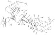
- FIG. 1is an exploded view of a door lock assembly embodying the present invention
- FIG. 2is a perspective view of a support structure of the door lock assembly
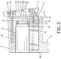
- FIG. 3is a sectional view taken along a longitudinal plane extending longitudinally through a handle device and a spindle tube of the door lock assembly;
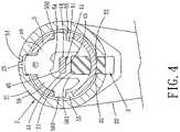
- FIG. 4is another sectional view taken along line 4 - 4 of FIG. 3 ;
- FIG. 5is the same view as FIG. 3 but showing a tailpiece in a first position thereof;
- FIG. 6is the same view as FIG. 4 but showing the tailpiece in the first position
- FIG. 7is the same view as FIG. 3 but showing that a retaining plate is pressed inward.
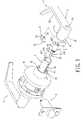
- FIG. 8shows another door lock assembly embodying the present invention.
- FIGS. 1 and 2there is shown a door lock assembly including an outer handle device 1 embodying the present invention, a conventional inner handle device 6 , and a conventional latching device 7 operated by the outer and inner handle devices 1 and 6 .
- the outer handle device 1generally includes a handle unit 2 , a support structure 3 , a lock unit 4 , and a spindle tube 5 .
- the lock unit 4is conventional, and includes a cylindrical case 401 receiving a key plug 43 , a tumbler case 402 connected to the cylindrical case 401 , and a tailpiece 41 connected integrally to the key plug 43 .
- the tailpiece 41has two diametrically opposite edges 44 interconnecting two opposite faces 45 .
- the key plug 43has a key slot 42 for insertion of a key (not shown). By operating the key plug 43 with the key, the tailpiece 41 is rotatable to a first position when the lock unit 4 is in a locking state, and a second position when the lock unit 4 is in an unlocking state.
- the handle unit 2includes a tubular body 21 , a handle 22 connected to the tubular body 21 .
- the tubular body 21has an axial hole composed of a cylindrical hole portion 23 receiving the cylindrical case 401 , and a non-cylindrical hole portion 24 communicated with the cylindrical hole portion 23 and receiving the tumbler case 402 .
- a retention slot 25is formed radially in the tubular body 21 in communication with the cylindrical hole portion 23 .
- the spindle tube 5extends into the cylindrical hole portion 23 of the tubular body 21 and surrounds the tailpiece 41 .
- a conventional outer rose assembly 59is connected to the spindle tube 5 .
- the spindle tube 5further has a passage opening 570 , and a bounding edge that bounds the passage opening 570 and that includes two opposite axial edge parts 571 and a circumferential edge part 572 ( FIG. 3 ).
- a retaining plate 51is disposed transversely inside the spindle tube 5 and has a retaining tongue 53 .
- a spring 52is disposed inside the spindle tube 5 to bias the retaining plate 51 so that the retaining tongue 53 projects out of the spindle tube 5 and extends into the retention slot 25 .
- the retaining plate 51further has a stabilizing part 54 projecting inwardly in a direction towards said tail piece 41 and extending between two arms 56 .
- the two arms 56project oppositely from the retaining tongue 53 , and extend on two sides of the tailpiece 41 .
- a spacing 561is thus formed between the arms 56 .
- Two lugs 560respectively project from the arms 56 in radial directions and into two slide slots 55 that are formed in the spindle tube 5 at two diametrically opposite positions.
- the support structure 3is disposed within the non-cylindrical hole portion 24 of the tubular body 21 and oppositely of the retention slot 25 .
- the tumbler case 402is adjacent to the support structure 3 .
- the support structure 3has a base part 30 disposed in the tubular body 21 , a support part 31 extending into the spindle tube 5 , a neck part 33 connected between the base part 30 and the support part 31 and passing through the passage opening 570 of the spindle tube 5 , and an engagement groove 32 formed between the base part 30 and the support part 31 and adjacent the neck part 33 .
- the support part 31projects radially into the spacing 561 between the two arms 56 within the spindle tube 5 . Further, the support part 31 is opposite to the stabilizing part 54 of the retaining plate 51 so that the tailpiece 41 is between the support part 31 and the stabilizing part 54 .
- the engagement groove 32engages the axial edge parts 571 and the circumferential edge part 572 of the spindle tube 5 so that the support structure 3 is positioned firmly to the spindle tube 5 .
- the engagement groove 32may be arranged to engage one or two of the axial edge parts 571 and the circumferential edge part 572 .
- the tailpiece 41is in the second position when the lock unit 4 is in the unlocking state, and the retaining tongue 53 of the retaining plate 51 extends into the retention slot 25 of the tubular body 21 .
- the edges 44 of the tailpiece 41are away from the stabilizing part 54 of the retaining plate 51 and the support part 31 of the support structure 3 . Therefore, when a tool (not shown) or a narrow strip (not shown) is inserted into the retention slot 25 of the tubular body 25 to press the retaining tongue 53 against the spring 52 , the retaining tongue 53 is moved inward and away from the retention slot 25 so that the handle unit 1 can be detached from the spindle tube 5 for replacement of the lock unit 4 .
- the tailpiece 41is in the first position when the lock unit 4 is the locking state, and the retaining tongue 53 extends into the retention slot 25 .
- the edges 44 of the tailpiece 41respectively move to the stabilizing part 54 of the retaining plate 51 and the support part 31 of the support structure 3 .
- the tool or the narrow strip(not shown) is inserted into the retention slot 25 to press the retaining tongue 53 of the retaining plate 51 , the retaining tongue 53 cannot move out of the retention slot 25 because the support part 31 abuts against one of the edges 44 of the tailpiece 41 and the other edge 44 abuts against the stabilizing part 54 of the retaining plate 41 .
- the handle unit 1cannot be detached from the spindle tube 5 , and the latching device 7 cannot be operated to unlock the door to which the latching device 7 is attached.
- FIG. 8there is shown another door lock assembly (B) having an outer handle device 1 embodying the present invention.
- the door lock assembly (B)is of a different type that includes a latch operator spindle 9 that is inserted into the spindle tube 5 and that has a tab (not shown) connected to a latch operator or retractor 8 .
- the latch operator or retractor 8is in turn connected to the latching device 7 .
- the present inventionmay also be embodied in other types of door lock assemblies.
Landscapes
- Engineering & Computer Science (AREA)
- Mechanical Engineering (AREA)
- Lock And Its Accessories (AREA)
- Aiming, Guidance, Guns With A Light Source, Armor, Camouflage, And Targets (AREA)
Abstract
Description
Claims (4)
Applications Claiming Priority (2)
| Application Number | Priority Date | Filing Date | Title |
|---|---|---|---|
| TW95217085UTWM309592U (en) | 2006-09-22 | 2006-09-22 | Support structure of transmission element for lock set |
| TW095217085 | 2006-09-22 |
Publications (2)
| Publication Number | Publication Date |
|---|---|
| US20080072634A1 US20080072634A1 (en) | 2008-03-27 |
| US7581421B2true US7581421B2 (en) | 2009-09-01 |
Family
ID=38644122
Family Applications (1)
| Application Number | Title | Priority Date | Filing Date |
|---|---|---|---|
| US11/858,274Active2027-10-22US7581421B2 (en) | 2006-09-22 | 2007-09-20 | Door lock assembly having a support structure to support a tailpiece and a retaining plate |
Country Status (3)
| Country | Link |
|---|---|
| US (1) | US7581421B2 (en) |
| CA (1) | CA2603301C (en) |
| TW (1) | TWM309592U (en) |
Cited By (7)
| Publication number | Priority date | Publication date | Assignee | Title |
|---|---|---|---|---|
| US20090120142A1 (en)* | 2007-10-12 | 2009-05-14 | Miao-Hsueh Tsai | Door Lock with An Improved Structure |
| US20100064745A1 (en)* | 2008-09-17 | 2010-03-18 | Cheng-Chung Liu | Lock with a support structure |
| USD660128S1 (en)* | 2011-02-16 | 2012-05-22 | Tong Lung Metal Industry Co., Ltd. | Door lever |
| US20120304712A1 (en)* | 2011-06-02 | 2012-12-06 | Tong Lung Metal Industry Co., Ltd. | Push-button type cylinder lock assembly |
| US20140196566A1 (en)* | 2013-01-17 | 2014-07-17 | Taiwan Fu Hsing Industrial Co., Ltd. | Rotation assembly |
| US20140290427A1 (en)* | 2013-04-02 | 2014-10-02 | Taiwan Fu Hsing Industrial Co., Ltd. | Handle assembly of lock |
| US20220205278A1 (en)* | 2019-02-11 | 2022-06-30 | Spectrum Brands, Inc. | Support structure for handle assembly |
Families Citing this family (2)
| Publication number | Priority date | Publication date | Assignee | Title |
|---|---|---|---|---|
| US20240102312A1 (en)* | 2022-09-28 | 2024-03-28 | Schlage Lock Company Llc | Modular cylinder spacers |
| CN117306952B (en)* | 2023-10-30 | 2025-08-01 | 浙江瀚运五金有限公司 | Lock and door lock |
Citations (21)
| Publication number | Priority date | Publication date | Assignee | Title |
|---|---|---|---|---|
| US666800A (en)* | 1900-01-09 | 1901-01-29 | Minerva A Chase | Door-knob fastener. |
| US736290A (en)* | 1903-02-24 | 1903-08-11 | New York Lock Company | Knob. |
| US1820504A (en)* | 1929-03-29 | 1931-08-25 | Simon Robert | Locking door handle |
| US1831043A (en)* | 1930-09-03 | 1931-11-10 | Nathaniel B Stone | Doorknob construction |
| US1874139A (en)* | 1932-02-01 | 1932-08-30 | Nathaniel B Stone | Automatic spindle grip for doorknobs |
| US1988130A (en)* | 1933-12-14 | 1935-01-15 | Martinek Frederick | Doorknob fastener |
| US2062765A (en)* | 1934-10-22 | 1936-12-01 | Schlage Lock Co | Doorknob and spindle fastener |
| US2301751A (en)* | 1940-05-29 | 1942-11-10 | Schlage Lock Co | Demountable knob and cylinder lock |
| US2827323A (en)* | 1956-01-18 | 1958-03-18 | Dexter Ind Inc | Knob couplings |
| US2961268A (en)* | 1959-06-01 | 1960-11-22 | Russell | Knob retainer |
| US2976073A (en)* | 1959-05-25 | 1961-03-21 | Russell | Knob assembly |
| US3212306A (en)* | 1964-01-06 | 1965-10-19 | Russell | Combination hand-hold retainer and key-operated mechanism retainer |
| US4394821A (en)* | 1981-06-05 | 1983-07-26 | Best Lock Corporation | Door lock mechanism |
| US4428570A (en)* | 1981-12-02 | 1984-01-31 | Best Lock Corporation | Tool-loadable biasing spring |
| US4655059A (en)* | 1981-06-05 | 1987-04-07 | Best Lock Corporation | Lever handle |
| US5077994A (en)* | 1991-04-05 | 1992-01-07 | Yale Security Inc. | Door lock having removable outside lever handle for the purpose of changing the key cylinder |
| US5704234A (en)* | 1995-10-11 | 1998-01-06 | Strattec Security Corporation | Cylinder lock incorporating a slam resistance pad |
| US5782119A (en)* | 1996-07-19 | 1998-07-21 | Baldwin Hardware Corporation | Biased detent for door knob assembly |
| US6029484A (en)* | 1998-12-07 | 2000-02-29 | Jetton; James E. | Secure door handle |
| US6948748B2 (en)* | 2003-12-11 | 2005-09-27 | Newfrey Llc | Door handle spring assembly |
| US7156432B2 (en)* | 2004-05-24 | 2007-01-02 | Newfrey, Llc | Operator catch cartridge assembly for a door handle set |
- 2006
- 2006-09-22TWTW95217085Upatent/TWM309592U/ennot_activeIP Right Cessation
- 2007
- 2007-09-20USUS11/858,274patent/US7581421B2/enactiveActive
- 2007-09-20CACA2603301Apatent/CA2603301C/enactiveActive
Patent Citations (21)
| Publication number | Priority date | Publication date | Assignee | Title |
|---|---|---|---|---|
| US666800A (en)* | 1900-01-09 | 1901-01-29 | Minerva A Chase | Door-knob fastener. |
| US736290A (en)* | 1903-02-24 | 1903-08-11 | New York Lock Company | Knob. |
| US1820504A (en)* | 1929-03-29 | 1931-08-25 | Simon Robert | Locking door handle |
| US1831043A (en)* | 1930-09-03 | 1931-11-10 | Nathaniel B Stone | Doorknob construction |
| US1874139A (en)* | 1932-02-01 | 1932-08-30 | Nathaniel B Stone | Automatic spindle grip for doorknobs |
| US1988130A (en)* | 1933-12-14 | 1935-01-15 | Martinek Frederick | Doorknob fastener |
| US2062765A (en)* | 1934-10-22 | 1936-12-01 | Schlage Lock Co | Doorknob and spindle fastener |
| US2301751A (en)* | 1940-05-29 | 1942-11-10 | Schlage Lock Co | Demountable knob and cylinder lock |
| US2827323A (en)* | 1956-01-18 | 1958-03-18 | Dexter Ind Inc | Knob couplings |
| US2976073A (en)* | 1959-05-25 | 1961-03-21 | Russell | Knob assembly |
| US2961268A (en)* | 1959-06-01 | 1960-11-22 | Russell | Knob retainer |
| US3212306A (en)* | 1964-01-06 | 1965-10-19 | Russell | Combination hand-hold retainer and key-operated mechanism retainer |
| US4394821A (en)* | 1981-06-05 | 1983-07-26 | Best Lock Corporation | Door lock mechanism |
| US4655059A (en)* | 1981-06-05 | 1987-04-07 | Best Lock Corporation | Lever handle |
| US4428570A (en)* | 1981-12-02 | 1984-01-31 | Best Lock Corporation | Tool-loadable biasing spring |
| US5077994A (en)* | 1991-04-05 | 1992-01-07 | Yale Security Inc. | Door lock having removable outside lever handle for the purpose of changing the key cylinder |
| US5704234A (en)* | 1995-10-11 | 1998-01-06 | Strattec Security Corporation | Cylinder lock incorporating a slam resistance pad |
| US5782119A (en)* | 1996-07-19 | 1998-07-21 | Baldwin Hardware Corporation | Biased detent for door knob assembly |
| US6029484A (en)* | 1998-12-07 | 2000-02-29 | Jetton; James E. | Secure door handle |
| US6948748B2 (en)* | 2003-12-11 | 2005-09-27 | Newfrey Llc | Door handle spring assembly |
| US7156432B2 (en)* | 2004-05-24 | 2007-01-02 | Newfrey, Llc | Operator catch cartridge assembly for a door handle set |
Cited By (12)
| Publication number | Priority date | Publication date | Assignee | Title |
|---|---|---|---|---|
| US20090120142A1 (en)* | 2007-10-12 | 2009-05-14 | Miao-Hsueh Tsai | Door Lock with An Improved Structure |
| US8113021B2 (en)* | 2007-10-12 | 2012-02-14 | Imperial (Asia) Limited | Door lock with an improved structure |
| US20100064745A1 (en)* | 2008-09-17 | 2010-03-18 | Cheng-Chung Liu | Lock with a support structure |
| US8087273B2 (en) | 2008-09-17 | 2012-01-03 | Tong Lung Metal Industry Co., Ltd. | Lock with a support structure |
| USD660128S1 (en)* | 2011-02-16 | 2012-05-22 | Tong Lung Metal Industry Co., Ltd. | Door lever |
| US20120304712A1 (en)* | 2011-06-02 | 2012-12-06 | Tong Lung Metal Industry Co., Ltd. | Push-button type cylinder lock assembly |
| US8813530B2 (en)* | 2011-06-02 | 2014-08-26 | Tong Lung Metal Industry Co., Ltd. | Push-button type cylinder lock assembly |
| US20140196566A1 (en)* | 2013-01-17 | 2014-07-17 | Taiwan Fu Hsing Industrial Co., Ltd. | Rotation assembly |
| US20140290427A1 (en)* | 2013-04-02 | 2014-10-02 | Taiwan Fu Hsing Industrial Co., Ltd. | Handle assembly of lock |
| US9175499B2 (en)* | 2013-04-02 | 2015-11-03 | Taiwan Fu Hsing Industrial Co., Ltd. | Handle assembly of lock |
| US20220205278A1 (en)* | 2019-02-11 | 2022-06-30 | Spectrum Brands, Inc. | Support structure for handle assembly |
| US12297662B2 (en)* | 2019-02-11 | 2025-05-13 | Assa Abloy Americas Residential Inc. | Support structure for handle assembly |
Also Published As
| Publication number | Publication date |
|---|---|
| CA2603301C (en) | 2014-04-15 |
| TWM309592U (en) | 2007-04-11 |
| CA2603301A1 (en) | 2008-03-22 |
| US20080072634A1 (en) | 2008-03-27 |
Similar Documents
| Publication | Publication Date | Title |
|---|---|---|
| US7581421B2 (en) | Door lock assembly having a support structure to support a tailpiece and a retaining plate | |
| US8607600B2 (en) | Pin locking device | |
| US7958757B1 (en) | Cam lock for a cabinet | |
| US7448236B2 (en) | Coupler latch lock and method of use | |
| US9228373B2 (en) | Combination-identifiable padlock | |
| CN107013097B (en) | Padlock | |
| US9200473B2 (en) | Rekeyable lock cylinder, rekeyable padlock and method of rekeying | |
| US8584495B2 (en) | Exchangeable cylinder lock assembly | |
| JP2010506069A (en) | Method and operation of a lock assembly capable of resetting a key | |
| JP2011256634A (en) | Key and locking device | |
| CN1849434B (en) | Cylinder lock | |
| US6981396B1 (en) | Exchangeable lock construction | |
| JP4657284B2 (en) | Front-mounting lock assembly | |
| US20060096344A1 (en) | Cylinder lock | |
| US8387423B2 (en) | Bicycle lock set connected with bicycle frame | |
| US6698264B1 (en) | Core assembly for a lock | |
| US6823703B2 (en) | Removable plug cylinder lock | |
| US4545225A (en) | Latch and lock assembly | |
| JP2649893B2 (en) | Inner cylinder replaceable cylinder lock | |
| US6854307B2 (en) | Lock-picking prevention apparatus | |
| US20160130837A1 (en) | Lock assembly | |
| CN111441673B (en) | Concealed Shackle Padlock Based on Cylinder Replacement | |
| JP4403395B2 (en) | Cylinder lock | |
| KR200307237Y1 (en) | Door knob | |
| JP2542160B2 (en) | Locking device |
Legal Events
| Date | Code | Title | Description |
|---|---|---|---|
| AS | Assignment | Owner name:TONG LUNG METAL INDUSTRY CO., LTD., TAIWAN Free format text:ASSIGNMENT OF ASSIGNORS INTEREST;ASSIGNORS:DON, LAN-KUN;CHEN, PO-YANG;KUO, CHING-CHUAN;REEL/FRAME:019855/0900 Effective date:20070910 | |
| STCF | Information on status: patent grant | Free format text:PATENTED CASE | |
| FPAY | Fee payment | Year of fee payment:4 | |
| AS | Assignment | Owner name:STANLEY SECURITY SOLUTIONS TAIWAN LTD., TAIWAN Free format text:ASSIGNMENT OF ASSIGNORS INTEREST;ASSIGNOR:TONG LUNG METAL INDUSTRY CO., LTD.;REEL/FRAME:033750/0497 Effective date:20140827 | |
| FEPP | Fee payment procedure | Free format text:PAT HOLDER CLAIMS SMALL ENTITY STATUS, ENTITY STATUS SET TO SMALL (ORIGINAL EVENT CODE: LTOS); ENTITY STATUS OF PATENT OWNER: SMALL ENTITY | |
| FPAY | Fee payment | Year of fee payment:8 | |
| AS | Assignment | Owner name:TUNG LUNG HARDWARE MANUFACTURING CO., LTD., TAIWAN Free format text:CHANGE OF NAME;ASSIGNOR:STANLEY SECURITY SOLUTIONS TAIWAN LTD.;REEL/FRAME:042763/0092 Effective date:20170501 | |
| AS | Assignment | Owner name:TLHM CO., LTD., TAIWAN Free format text:CHANGE OF NAME;ASSIGNOR:TUNG LUNG HARDWARE MANUFACTURING CO., LTD.;REEL/FRAME:044907/0254 Effective date:20170804 | |
| MAFP | Maintenance fee payment | Free format text:PAYMENT OF MAINTENANCE FEE, 12TH YR, SMALL ENTITY (ORIGINAL EVENT CODE: M2553); ENTITY STATUS OF PATENT OWNER: SMALL ENTITY Year of fee payment:12 |