US7581119B2 - Method and system for discovering a power source on a peripheral bus - Google Patents
Method and system for discovering a power source on a peripheral busDownload PDFInfo
- Publication number
- US7581119B2 US7581119B2US11/031,288US3128805AUS7581119B2US 7581119 B2US7581119 B2US 7581119B2US 3128805 AUS3128805 AUS 3128805AUS 7581119 B2US7581119 B2US 7581119B2
- Authority
- US
- United States
- Prior art keywords
- power
- electrical device
- recited
- peripheral bus
- level
- Prior art date
- Legal status (The legal status is an assumption and is not a legal conclusion. Google has not performed a legal analysis and makes no representation as to the accuracy of the status listed.)
- Active, expires
Links
Images


Classifications
- G—PHYSICS
- G06—COMPUTING OR CALCULATING; COUNTING
- G06F—ELECTRIC DIGITAL DATA PROCESSING
- G06F1/00—Details not covered by groups G06F3/00 - G06F13/00 and G06F21/00
- G06F1/26—Power supply means, e.g. regulation thereof
- G06F1/266—Arrangements to supply power to external peripherals either directly from the computer or under computer control, e.g. supply of power through the communication port, computer controlled power-strips
- G—PHYSICS
- G06—COMPUTING OR CALCULATING; COUNTING
- G06F—ELECTRIC DIGITAL DATA PROCESSING
- G06F1/00—Details not covered by groups G06F3/00 - G06F13/00 and G06F21/00
- G06F1/26—Power supply means, e.g. regulation thereof
- G—PHYSICS
- G06—COMPUTING OR CALCULATING; COUNTING
- G06F—ELECTRIC DIGITAL DATA PROCESSING
- G06F1/00—Details not covered by groups G06F3/00 - G06F13/00 and G06F21/00
- G06F1/26—Power supply means, e.g. regulation thereof
- G06F1/30—Means for acting in the event of power-supply failure or interruption, e.g. power-supply fluctuations
Definitions
- the present inventionrelates to electronic devices and, more particularly, to portable electronic devices that can couple to peripheral buses.
- Portable electronic devicessuch as Portable Digital Assistants and media players, are often battery powered. These electronic devices sometimes also have peripheral bus ports that are able to support peripheral buses, such as Universal Serial Bus (USB) or FIREWIRE (IEEE 1394) bus ports. Peripheral buses are used to provide data communications with electronic devices as well as to provide limited amounts of power to the electronic devices.
- USBUniversal Serial Bus
- FIREWIREIEEE 1394
- the iPod®a media player developed by Apple Computer, Inc. of Cupertino, Calif.
- the iPod®has been able to charge its battery through power provided to its FIREWIRE bus port.
- peripheral busesare not designed to carry large amounts of power.
- the available poweris limited to about 0.5 Watts but can be increased to about 2.5 Watts through a negotiation process.
- the negotiation processcumbersome, but the amount of power (even when increased through negotiation) is still often inadequate for many electronic devices.
- the inventionrelates to improved techniques to recognize a power source on a peripheral bus and/or determine power available from the power source via the peripheral bus.
- the peripheral busis supported by a cable connected between a host device and an electronic device.
- the host deviceis a power source (e.g., power adapter or battery pack) and the cable is used to provide power from the power source to the electronic device.
- the electronic devicecan manage its power utilization so as to operate in a stable and reliable manner.
- the electronic deviceis, for example, a portable computing device. Examples of portable computing devices include a Portable Digital Assistant (PDA) and a portable media player.
- PDAPortable Digital Assistant
- the inventioncan be implemented in numerous ways, including as a method, system, device, apparatus, or computer readable medium. Several embodiments of the invention are discussed below.
- one embodiment of the inventionincludes at least: a bus interface coupled to a bus connector, the bus connector providing a power line, a ground line and a plurality of data lines to the bus interface; an available power detector operatively connected to the bus interface, the available power detector operates to detect a level of available power from the power line when a power source is operatively connected to the bus interface via the bus connector; power-consuming circuitry; and a power manager operatively connected to the available power detector and the power-consuming circuitry, the power manager operates to manage power utilization by at least a portion of the power-consuming circuitry based on the level of available power.
- one embodimentincludes at least the acts of: detecting connection of a peripheral bus to a bus connector of the electrical device, the peripheral bus having at least a power line and a plurality of bus data lines; reading voltage levels on the bus data lines when the detecting detects connection of the peripheral bus; determining whether a host device providing the peripheral bus is a power adapter based on the voltage levels; and determining an available power level for the power adapter based on the voltage levels when it is determines that the host device is a power adapter; and managing power utilization of the electrical device based on the available power level for the power adapter.
- another embodimentincludes at least the acts of: detecting connection of a peripheral bus to a bus connector of the electrical device, the peripheral bus having at least a power line and a plurality of bus data lines; reading voltage levels on the bus data lines when said detecting detects connection of the peripheral bus; determining whether a host device providing the peripheral bus is a battery pack based on the voltage levels; and determining an available power capacity of the battery pack based on the voltage levels when it is determined that the host device is a battery pack; and managing power utilization of the electrical device based on the available power capacity of the battery pack.
- one embodiment of the inventionincludes at least the acts of: reading voltage levels induced on the bus data lines by the power adapter; and determining an available power level for the power adapter based on the voltage levels.
- another embodiment of the inventionincludes at least the acts of: reading voltage levels induced on the bus data lines by the battery pack; and determining an available power level for the battery pack based on the voltage levels.
- one embodiment of the inventionincludes at least the acts of: detecting connection of a peripheral bus to the bus connector of the electrical device, the peripheral bus being associated with a host device that is also connected to the peripheral bus, the peripheral bus having at least a power line and a plurality of bus data lines; reading voltage levels on the bus data lines after the detecting detects connection of the peripheral bus; and identifying the host device as a power adapter or battery pack based on the voltage levels.
- FIG. 1Ais a block diagram of a power delivery system according to one embodiment of the invention.
- FIG. 1Bis a block diagram of a power delivery system according to another embodiment of the invention.
- FIG. 2Ais a block diagram of a power adapter according to one embodiment of the invention.
- FIG. 2Bis a block diagram of a battery pack according to one embodiment of the invention.
- FIG. 3Ais a schematic diagram of a resistor arrangement according to one embodiment of the invention.
- FIG. 3Billustrates a resistor arrangement according to another embodiment of the invention.
- FIG. 3Cillustrates a resistor arrangement according to another embodiment of the invention.
- FIG. 4Aillustrates a table that provides a representative correlation of high voltage level to available power.
- FIG. 4Billustrates a table that provides a representative correlation of high voltage level to available power.
- FIG. 5is a block diagram of an electronic device according to one embodiment of the invention.
- FIG. 6is a schematic diagram of an analog-to-digital conversion circuit according to one embodiment of the invention.
- FIG. 7is a block diagram of a power management system according to one embodiment of the invention.
- FIG. 8is a flow diagram of an available power process according to one embodiment of the invention.
- FIG. 9is a flow diagram of a boot process according to one embodiment of the invention.
- FIG. 10is a block diagram of a media player suitable for use with the invention.
- the inventionrelates to improved techniques to recognize a power source on a peripheral bus and/or determine power available from the power source via the peripheral bus.
- the peripheral busis supported by a cable connected between a host device and an electronic device.
- the host deviceis a power source (e.g., power adapter or battery pack) and the cable is used to provide power from the power source to the electronic device.
- the electronic devicecan manage its power utilization so as to operate in a stable and reliable manner.
- the electronic deviceis, for example, a portable computing device. Examples of portable computing devices include a Portable Digital Assistant (PDA) and a portable media player.
- PDAPortable Digital Assistant
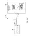
- FIG. 1Ais a block diagram of a power delivery system 100 according to one embodiment of the invention.
- the power delivery system 100includes a power adapter 102 .
- the power adapter 102can couple to an alternating current (AC) outlet by way of an AC plug 104 and a power cord 106 .
- AC poweris supplied to the power adapter 102 from the AC outlet via the AC plug 104 and the power cord 106 .
- the AC poweris converted to direct current (DC) power.
- the DC poweris coupled to a peripheral connector 108 of the power adapter 102 so that the DC power is available for use by other devices.
- the peripheral connector 108can be a Universal Serial Bus (USB) connector.
- the peripheral connector 108can be a FIREWIRETM connector.
- the peripheral connector 108can receive a counterpart connector of one end of a peripheral cable 110 .
- the peripheral cable 110is used to provide the DC power from the peripheral connector 108 of the power adapter 102 to an electronic device 112 .
- the opposite end of the peripheral cable 110has a counterpart connector that couples to a peripheral connector 114 of the electronic device 112 .
- the electronic device 112receives the DC power made available by the power adapter 102 via the peripheral cable 110 .
- the power adapter 102can be considered a host device, at least for power, and the other devices that receive the power via the peripheral connector 108 can be considered peripheral devices, at least for power.
- the DC power supplied to the electronic device 112 by the peripheral cable 110can be consumed by the electronic device 112 .
- the power adapter 102is designed to provide only a certain, limited amount of power.
- proper design of the electronic circuit 112would dictate that the electronic circuit 112 respect the certain, limited amount of power made available by the power adapter 102 .
- the electronic device 112includes a power manager 116 .
- the power manager 116can operate power consuming circuitry 118 within the electronic device 112 such that the available power from the power adapter 102 is not over-consumed. Hence, the operation of the electronic device 112 remains stable even when connected to different power adapters that provide different limited amounts of power.
- the power manager 116can disable, limit or sequence usage of various circuits of the power consuming circuitry 118 such that the power being consumed is normally not more than the certain, limited amount of power made available by the power adapter 102 .
- a batterycan be provided within the electronic device 112 to provide power when the power adapter 102 is not connected, or can provide supplemental power (should it be needed) when the power adapter 102 is connected.
- FIG. 1Bis a block diagram of a power delivery system 150 according to another embodiment of the invention.
- the power delivery system 150is generally similar to the power delivery system 100 shown in FIG. 1A except that the power adapter 102 is replaced by a battery pack 150 .
- the battery pack 150provides direct current (DC) power.
- the peripheral cable 110is used to provide the DC power from the battery pack 150 to the electronic device 112 .
- the DC power supplied to the electronic device 112 by the peripheral cable 110can be consumed by the electronic device 112 .
- the battery pack 150is designed to provide only a certain, limited amount of power.
- the electronic circuit 112would dictate that the electronic circuit 112 respect the certain, limited amount of power made available by the battery pack 152 .
- the power available from the battery pack 150is dependent on the type and quantity of batteries provided in the battery pack 150 .
- the power manager 116can operate power consuming circuitry 118 within the electronic device 112 such that the available power from the battery pack 152 is not over-consumed. Hence, the operation of the electronic device 112 remains stable even when connected to different battery packs that provide different limited amounts of power.
- the power manager 116can disable, limit or sequence usage of various circuits of the power consuming circuitry 118 such that the power being consumed is normally not more than the certain, limited amount of power made available by the battery pack 152 .
- a batterycan be provided within the electronic device 112 to provide power when the battery pack 152 is not connected, or can provide supplemental power (should it be needed) when the battery pack 152 is connected.
- FIG. 2Ais a block diagram of a power adapter 200 according to one embodiment of the invention.
- the power adapter 200is, for example, suitable for use as the power adapter 102 illustrated in FIG. 1A .
- the power adapter 200includes an AC/DC converter 202 and an available power indicator 204 .
- the AC/DC converter 202can receive AC power from the AC outlet via the AC plug 104 and the power cord 106 .
- the AC poweris then converted to DC power by the AC/DC converter 202 .
- the DC poweris then coupled to a power line of a peripheral connector 206 .
- a ground lineis also coupled to the peripheral connector 206 .
- the available power indicator 204also couples to the DC power and the ground line.
- the available power indicator 204provides an available power indication.
- the available power indicationindicates the amount of available power offered by the power adapter 200 .
- the available power indication provided by the available power indicator 204is coupled to data lines of the peripheral connector 206 , such as data lines DP and DM shown in FIG. 2A .
- the available power indicator 204can be implemented in a variety of different ways.
- the available power indicator 204couples analog voltage levels to the data lines DP and DM of the peripheral connector 206 .
- the voltages levelscan be used to indicate the available power provided by the power adapter 200 .
- the voltage levels on the data linescan be used directly or in a differential manner.
- signalingcould be utilized over the data lines. The signaling could pertain to a digital signal or could pertain to signals using a frequency or pulse-width modulation scheme.
- FIG. 2Bis a block diagram of a battery pack 250 according to one embodiment of the invention.
- the battery pack 250is, for example, suitable for use as the battery pack 152 illustrated in FIG. 1B .
- the battery pack 250includes one or more batteries 252 and a DC/DC regulator 254 .
- the DC/DC regulatoroperates to regulate the DC power provided by the one or more batteries 252 .
- the battery pack 250also includes the available power indicator 204 .
- the DC poweris then coupled to a power line of a peripheral connector 206 .
- a ground lineis also coupled to the one or more batteries 252 and the peripheral connector 206 .
- the available power indicator 204provides an available power indication.
- the available power indicationindicates the amount of available power offered by the battery pack 250 .
- the available power indication provided by the available power indicator 204is coupled to data lines of the peripheral connector 206 , such as data lines DP and DM shown in FIG. 2B .
- the available power indicator 204When the available power indicator 204 is implemented to apply analog voltage levels to the data lines DP and DM, the available power indicator 204 can be implemented by a resistor arrangement.
- FIGS. 3A-3Cillustrate different representative resistor arrangements that can be utilized to implement the available power indicator 204 according to certain embodiments of the invention.
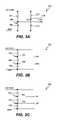
- FIG. 3Ais a schematic diagram of a resistor arrangement 300 according to one embodiment of the invention.
- the resistor arrangement 300includes a first resistor 302 coupled between DC power (DC PWR) and a first node 304 .
- a second resistor 306is coupled between the first node 304 and ground (GND).
- a third resistor 308is coupled between DC power and a second node 310 .
- a fourth resistor 312is coupled between the second node 310 and ground.
- the data line DPis coupled to the second node 310
- the data line DMis coupled to the first node 304 .
- the voltage V DP which appears at the second node 310is placed on the data line DP
- the voltage V DM which appears at the first node 304is placed on the data line DM.
- FIG. 3Billustrates a resistor arrangement 320 according to another embodiment of the invention.
- the resistor arrangement 320includes a first resistor 322 coupled between DC power and a first node 324 .
- a second resistor 326is coupled between the first node 324 and a second node 328 .
- a third resistor 330is coupled between the second node 328 and ground.
- the data line DPis coupled to the first node 324 so as to place a voltage V DP on the data line DP.
- the data line DMis coupled to the second node 328 to supply the voltage V DM on the data line DM.
- FIG. 3Cillustrates a resistor arrangement 340 according to another embodiment of the invention.
- a first resistor 342is coupled between DC power and a first node 344 .
- a second resistor 346is coupled between the first node 344 and a second node 348 .
- a third resistor 350is coupled between the second node 348 and ground.
- the data line DMis coupled to the first node 344 to supply the voltage V DM to the data line DM.
- the data line DPis coupled to the second node 348 to supply the voltage V DP to the data line DP.
- the voltages being coupled to the data lines DP and DMcan be used directly or in a differential manner.
- the advantage of using a differential voltageis that the number of gradations of available power levels that can be detected is increased (e.g., doubled).
- the resistor arrangement 320 in FIG. 3Bguarantees that the voltage V DP is always going to be greater than the voltage V DM .
- the resistor arrangement 340 in FIG. 3Cguarantees that the voltage V DM is always going to be greater than the voltage V DP .
- the resister arrangements 320 and 340are particularly well suited with the differential voltage approach.
- the voltages V DP and V DM appearing on the data lines DP and DM, respectivelyare always going to be considered “High” by the electronic device 112 . That is, these voltage levels will be greater than the minimum high level voltage that is used to determine whether the voltage at the data line is “High” or “Low”. Hence, although these voltages are “High,” the voltages can exceed the minimum high level by different amounts so as to provide gradations of high level voltages. These different gradations can be utilized to signal to the electronic device 112 the particular amount of available power offered by the power adapter 102 .
- FIG. 4Aillustrates a table 400 that provides a representative correlation of high voltage level to available power.
- a high voltage level H 1can indicate that the corresponding power source can supply 0.5 Watts of available power.
- the power sourcecan be a power adapter or a battery pack.
- a high voltage level H 2can indicate that the corresponding power source can supply 1 Watt of available power.
- a high voltage level H 3can indicate that the corresponding power source can supply 3.0 Watts of available power.
- the n th high voltage level (H n )can indicate that the corresponding power source can supply 8.0 Watts of available power.
- H ncan vary depending upon implementation, these voltage levels are all “High” level. For example, if the peripheral bus deems voltages from 2.0-3.3 Volts as “High,” then the high voltage levels H 1 , H 2 , H 3 , . . . , H n represent distinct, non-overlapping voltages or voltage ranges all within the range of 2.0 Volts and 3.3 Volts.
- FIG. 4Billustrates a table 450 that provides a representative correlation of high voltage level to available power.
- the table 450is suitable for use when the power source is a battery pack.
- the table 450can indicate characteristics of the battery pack, which indirectly provide an indication of available power.
- a high voltage level H 1can indicate that the corresponding battery pack has one AA battery.
- a high voltage level H 2can indicate that the corresponding battery pack has two AA batteries.
- a high voltage level H 3can indicate that the corresponding battery pack has two AAA batteries.
- the n th high voltage level (H n )can indicate that the corresponding battery pack has three AAA batteries.
- the high voltage levels H 1 , H 2 , H 3 , . . . , H ncan vary depending upon implementation, these voltage levels are all “High” level.
- the sign (positive or negative) of the voltage differencecan be used to distinguish different power sources. For example, if the voltage difference is positive, the power source can be deemed a power adapter. Alternatively, if the voltage difference is negative, the power source can be deemed a battery pack. The magnitude of the voltage difference can then be used as noted above to directly or indirectly signify level of power availability.
- FIG. 5is a block diagram of an electronic device 500 according to one embodiment of the invention.
- the electronic device 500can, for example, represent the electronic device 112 illustrated in FIGS. 1A and 1B .
- the electronic device 500couples to or includes a peripheral connector 502 .
- the peripheral connector 502is coupled to a DC power (DC PWR) line, a data DP line, a data DM line, and a ground (GND) line. These lines are supplied to a bus interface 504 .
- the bus interface 504enables the electronic device 500 to receive power and/or participate in data transmissions and receptions over a peripheral bus. Since the invention is primarily concerned with receiving power over the peripheral bus, the discussion below is primarily directed to receiving power at the electronic device 500 over the peripheral bus and then managing power utilization to ensure stable operation.
- the electronic device 500further includes an analog-to-digital conversion circuit 506 .
- the analog-to-digital conversion circuit 506couples to the data lines DP and DM.
- the analog-to-digital conversion circuit 506converts the analog voltage levels on the data lines DP and DM to digital voltage levels that are supplied to a controller 508 . More particularly, the digital voltage levels are supplied to an available power detector 510 .
- the available power detector 510is provided within the controller 508 .
- the controller 508is typically an integrated circuit, such as a microprocessor, custom IC (e.g., ASIC), or programmable IC that has been programmed.
- the available power detector 510examines the digital voltage levels to determine an available power level.
- the available power levelrepresents an amount of available power that is available to the electronic device 500 from a power source via the peripheral bus. Once the available power level is determined, the available power level is provided to a power manager 512 . In this embodiment, the power manager 512 is provided within the controller 508 . The power manager 512 operates to control the operational activity of the electronic device 500 so that its power draw via the peripheral bus does not normally exceed the power available from the power source. In this regard, the power manager 512 may cause the controller 508 or other power consuming circuitry 514 to defer operations, sequence operations, or avoid operations so that the power consumption of the electronic device 500 is managed.
- the electronic device 500would be a battery-powered device and that a rechargeable battery within the electronic device 500 could be charged by the power provided over the peripheral bus.
- the charging operationmay affect the amount of power available for other circuitry within the electronic device 500 .
- the batterymay offer additional power for consumption by the electronic device 500 in the event that the available power offered by the power source via the peripheral bus is exceeded by operational activity of the electronic device 500 .
- Examples of the other power consuming circuitry 514will vary widely depending upon implementation. Nevertheless, some examples of other power consuming circuitry 514 include a disk drive, a battery charge circuit, a memory device (e.g., RAM, ROM), a battery monitor, and a display.
- the available power detector 510 and the power manager 512are provided within the controller 508 .
- the available power detector 510 and the power manager 512need not be provided within the controller 508 and can also be separate components or integrated together.
- FIG. 6is a schematic diagram of an analog-to-digital conversion circuit 600 according to one embodiment of the invention.
- the analog-to-digital conversion circuit 600is, for example, suitable for use as the analog-to-digital conversion circuit 506 illustrated in FIG. 5 .
- the analog-to-digital conversion circuit 600includes resistors 602 and 604 and an analog-to-digital converter (ADC) 606 for converting an analog voltage on the data line DP to a digital output of n-bits.
- ADCanalog-to-digital converter
- resistors 608 and 610 and an ADC 612convert an analog voltage on the data line DM to a digital output of n-bits.
- the conversion circuitrycould be shared for the data lines DP and DM through use of a switch or multiplexer and only a portion of the analog-to-digital conversion circuit 600 .
- a switch or multiplexercould selectively couple one of the data line DM or DP to the resistor 602 , and then the output of the ADC 606 can be the digital voltage on the data line DM or on the data line DP, thus eliminating the need for the resistors 608 and 610 as well as the ADC 612 .
- FIG. 7is a block diagram of a power management system 700 according to one embodiment of the invention.
- the power management system 700describes a representative operation of a power manager, such as the power manager 512 , according to one embodiment of the invention.
- the power management system 700represents a portion of an electronic device.
- the power management system 700includes a power manager 702 .
- the power manager 702receives an available power level (APL) from an available power detector, such as the available power detector 510 .
- the power manager 702operates to control operation of electronic circuitry based on the available power level.
- the power management system 700can couple to a battery 704 and a battery monitor 706 .
- the battery monitor 706can monitor a battery charge level (BCL) and provide the battery charge level to the power manager 702 .
- BCLbattery charge level
- the power manager 702can also control operation of electronic circuitry based on the battery charge level.
- the power manager 702can manage power consumption by the electronic device based on the available power level and/or the battery charge level.
- Power supplied to the electronic device by the power sourcecan be coupled to the battery 704 via a battery charge circuit 708 .
- the battery charge circuit 708can be controlled by the power manager 702 such that the power available from a power source can either be available for charging the battery 704 or can be prevented from being used to charge the battery 704 .
- the power management system 700also includes other power consuming circuitry 710 associated with the electronic device.
- the other power consuming circuitry 710can vary widely depending upon implementation. Nevertheless, some or all of the power consuming circuitry 710 can be controlled by the power manager 702 .
- the power manager 702could limit the use of certain circuitry, could cause circuitry too initiate in different sequences, could change usage of circuitry, etc.
- the power manager 702can make use of not only the available power level but also the battery charge level. As shown in FIG. 7 , power from the battery P BAT is combined with the power from the power source P IN to yield a device power P OUT .
- the device power P OUTis provided to at least the power manager 702 , the battery monitor 706 , and the other power consuming circuitry 710 .
- the power being drawn from the electronic devicecan exceed the power into the electronic device by the power amplifier, namely, power P IN , provided the difference in power is available from the battery P BAT .
- FIG. 8is a flow diagram of an available power process 800 according to one embodiment of the invention.
- the available power process 800is, for example, performed by an electronic device, such as the electronic device 112 illustrated in FIGS. 1A and 1B or the electronic device illustrated in FIG. 5 .
- the available power process 800begins with a decision 802 that determines whether a peripheral bus has been detected.
- the electronic devicecan monitor or be informed when a peripheral bus is coupled between a host and the electronic device.
- a power linee.g., DC PWR
- a positive voltage sourcee.g., 5 volts
- the available power process 800waits for the detection of a peripheral bus. In other words, the available power process 800 can be initiated or deemed invoked once the peripheral bus has been detected.
- voltage levelsare read 804 from bus data lines of the peripheral bus.
- the voltage levelscan be read from the data lines DP and DM, such as illustrated in FIG. 5 .
- a decision 806determines whether the host device is a power source.
- the peripheral bus being detectedcan be from various different devices (e.g., host devices), including a power source and a computer.
- the voltage levels on the bus data linescan signal the type of host device.
- the inventionis particularly suited for use with host devices that are power sources. More particularly, the voltage levels on the bus data lines can signal that the host device is a power source. In one implementation, the voltage levels being “High” on the bus data lines can signal the presence of a power source.
- the decision 806determines that the host device is not a power source
- other standard processing 808can be performed.
- the other standard processing 808may involve operations to facilitate the exchange of data between the computer and the electronic device.
- an available power level of the power sourceis determined 810 .
- the available power level of the power sourcecan be determined 810 by further examination of the voltage levels on the bus data lines.
- the voltage levels on the bus data linescan signal the power level available from the power source.
- the voltage levels on the bus data linescan be categorized into a plurality of “High” voltage levels H 1 , H 2 , H 3 , . . . , H n which are deemed to respectively correspond to different available power levels offered by the power source, namely, 0.5, 1, 3, . . . , 8 Watts.
- power utilization by the electronic devicecan be managed 812 in accordance with the determined available power level. That is, during operation of the electronic device, the power utilization can be controlled or managed such that operations or functions may vary depending upon the determined available power level.
- a decision 814determines whether the peripheral bus has been disconnected. When the decision 814 determines that the peripheral bus has not been disconnected, then the processing returns to repeat the decision 812 so that power utilization by the electronic device can continue to be managed. Alternatively, when the decision 814 determines that the peripheral bus has been disconnected, the processing returns to repeat the decision 802 and subsequent blocks so that the electronic device can again perform the available power process 800 when a peripheral bus is thereafter connected to the electronic device.
- boot processinvolves the initial start-up of an electronic device.
- the electronic device performing a boot processwould include a disk drive device that stores program code that is used for or to boot-up an operating system for the electronic device.
- FIG. 9is a flow diagram of a boot process 900 according to one embodiment of the invention.
- the electronic devicecan perform the boot process 900 to initiate the electronic device for operation.
- the boot process 900begins with a decision 902 that determines whether the determined available power level is greater than or equal to a minimum boot power level.
- the determined available power levelcan be determined at block 810 of the available power process illustrated in FIG. 8 .
- further processingis performed to determine whether its is an appropriate time to boot-up. More specifically, a battery charge level is read 904 .
- a decision 906determines whether the battery charge level is greater than or equal to a minimum charge level. When the decision 906 determines that the battery charge level is not greater than or equal to the minimum charge level, the battery is charged 908 and a boot sequence is delayed.
- the boot process 900returns to repeat the decision 906 so that the battery charge level can again be compared with the minimum charge level. Once the decision 906 determines that the battery charge level equals or exceeds the minimum charge level, then the boot process 900 permits the boot sequence to be performed 910 .
- the boot sequencecan be directly performed 910 .
- the boot process 900permits the boot sequence to be immediately performed if the determined available power level offered by the power source is deemed to exceed the minimum boot power level needed to properly operate the electronic device during the boot sequence.
- additional powermay be required to be drawn from the battery of the electronic device.
- the decision 906ensures that the battery has at least a minimum charge level before the boot sequence is able to be performed 910 . Following the performance 910 of the boot sequence, the boot process 900 is complete and ends.
- the electronic device as described hereincan be a media player capable of playing (including displaying) media items.
- the media itemscan pertain to audio items (e.g., audio files or songs), videos (e.g., movies) or images (e.g., photos).
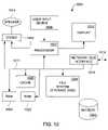
- FIG. 10is a block diagram of a media player 1000 suitable for use with the invention.
- the media player 1000can include the circuitry of the electronic device 112 in FIGS. 1A and 1B or the electronic device 500 in FIG. 5 , and/or can perform the operations described with reference to FIGS. 8 and 9 .
- the media player 1000includes a processor 1002 that pertains to a microprocessor or controller for controlling the overall operation of the media player 1000 .
- the media player 1000stores media data pertaining to media items in a file system 1004 and a cache 1006 .
- the file system 1004is, typically, a storage disk or a plurality of disks.
- the file system 1004typically provides high capacity storage capability for the media player 1000 .
- the media player 1000can also include a cache 1006 .
- the cache 1006is, for example, Random-Access Memory (RAM) provided by semiconductor memory.
- RAMRandom-Access Memory
- the cache 1006does not have the large storage capacity of the file system 1004 . Further, the file system 1004 , when active, consumes more power than does the cache 1006 . The power consumption is often a concern when the media player 1000 is a portable media player that is powered by a battery (not shown).
- the media player 1000also includes a RAM 1020 and a Read-Only Memory (ROM) 1022 .
- the ROM 1022can store programs, utilities or processes to be executed in a non-volatile manner.
- the RAM 1020provides volatile data storage, such as for the cache 1006 .
- the media player 1000also includes a user input device 1008 that allows a user of the media player 1000 to interact with the media player 1000 .
- the user input device 1008can take a variety of forms, such as a button, keypad, dial, etc.
- the media player 1000includes a display 1010 (screen display) that can be controlled by the processor 1002 to display information to the user.
- a data bus 1011can facilitate data transfer between at least the file system 1004 , the cache 1006 , the processor 1002 , and the CODEC 1012 .
- the media player 1000serves to store a plurality of media items (e.g., songs) in the file system 1004 .
- a userdesires to have the media player play a particular media item, a list of available media items is displayed on the display 1010 .
- the processor 1002upon receiving a selection of a particular media item, supplies the media data (e.g., audio file) for the particular media item to a coder/decoder (CODEC) 1012 .
- the CODEC 1012then produces analog output signals for a speaker 1014 .
- the speaker 1014can be a speaker internal to the media player 1000 or external to the media player 1000 . For example, headphones or earphones that connect to the media player 1000 would be considered an external speaker.
- the media player 1000also includes a bus interface 1016 that couples to a data link 1018 .
- the data link 1018allows the media player 1000 to couple to a host device (e.g., host computer or power source).
- the data link 1018can also provide power to the media player 1000 .
- the inventionis preferably implemented by hardware, software or a combination of hardware and software.
- the softwarecan also be embodied as computer readable code on a computer readable medium.
- the computer readable mediumis any data storage device that can store data which can thereafter be read by a computer system. Examples of the computer readable medium include read-only memory, random-access memory, CD-ROMs, DVDs, magnetic tape, optical data storage devices, and carrier waves.
- the computer readable mediumcan also be distributed over network-coupled computer systems so that the computer readable code is stored and executed in a distributed fashion.
- One advantage of the inventionis that a portable media device can easily and rapidly determine whether a power source is connected to its peripheral port and, if so, how much power can be drawn from the power source via the peripheral port.
- Another advantage of the inventionis that power utilization by a portable media device can be dependent on available power for stable and reliable operation.
Landscapes
- Engineering & Computer Science (AREA)
- Theoretical Computer Science (AREA)
- General Engineering & Computer Science (AREA)
- Physics & Mathematics (AREA)
- General Physics & Mathematics (AREA)
- Computer Hardware Design (AREA)
- Power Sources (AREA)
- Charge And Discharge Circuits For Batteries Or The Like (AREA)
Abstract
Description
Claims (42)
Priority Applications (15)
| Application Number | Priority Date | Filing Date | Title |
|---|---|---|---|
| US11/031,288US7581119B2 (en) | 2004-07-18 | 2005-01-07 | Method and system for discovering a power source on a peripheral bus |
| KR1020077003665AKR100947697B1 (en) | 2004-07-18 | 2005-07-12 | Method and system for discovering a power source on a peripheral bus |
| HK07110469.4AHK1102339B (en) | 2004-07-18 | 2005-07-12 | Method and system for discovering a power source on a peripheral bus |
| KR1020097006247AKR100997309B1 (en) | 2004-07-18 | 2005-07-12 | Electrical device, a method for identifying a peripheral device connected to a peripheral connector of the electrical device, a method for determining power availability from a power source connected to the electrical device through a peripheral bus, and for managing power usage by an electrical device having a bus connector. Way |
| EP05771312.5AEP1769313B1 (en) | 2004-07-18 | 2005-07-12 | Method and system for discovering a power source on a peripheral bus |
| PCT/US2005/024906WO2006019850A2 (en) | 2004-07-18 | 2005-07-12 | Method and system for discovering a power source on a peripheral bus |
| CNB2005800241789ACN100573417C (en) | 2004-07-18 | 2005-07-12 | Method and system for discovering power on external bus |
| EP20100161779EP2209059A1 (en) | 2004-07-18 | 2005-07-12 | Method and system for discovering a power source on a peripheral bus |
| JP2007522569AJP4664362B2 (en) | 2004-07-18 | 2005-07-12 | Electrical device, method for identifying host device, method for determining power availability of power supply, and method for managing power usage of electrical device |
| CN2009102087422ACN101694595B (en) | 2004-07-18 | 2005-07-12 | Method and system for discovering a power source on a peripheral bus |
| US12/506,740US7890783B2 (en) | 2004-07-18 | 2009-07-21 | Method and system for discovering a power source on a peripheral bus |
| JP2010153472AJP4695220B2 (en) | 2004-07-18 | 2010-07-05 | Power supply device and power supply method |
| US13/004,721US8332668B2 (en) | 2004-07-18 | 2011-01-11 | Method and system for discovering a power source on a peripheral bus |
| US14/312,672US9223958B2 (en) | 2005-01-07 | 2014-06-23 | Accessory authentication for electronic devices |
| US14/979,456US9754099B2 (en) | 2005-01-07 | 2015-12-27 | Accessory authentication for electronic devices |
Applications Claiming Priority (3)
| Application Number | Priority Date | Filing Date | Title |
|---|---|---|---|
| US58895904P | 2004-07-18 | 2004-07-18 | |
| US60895904P | 2004-10-08 | 2004-10-08 | |
| US11/031,288US7581119B2 (en) | 2004-07-18 | 2005-01-07 | Method and system for discovering a power source on a peripheral bus |
Related Child Applications (1)
| Application Number | Title | Priority Date | Filing Date |
|---|---|---|---|
| US12/506,740DivisionUS7890783B2 (en) | 2004-07-18 | 2009-07-21 | Method and system for discovering a power source on a peripheral bus |
Publications (2)
| Publication Number | Publication Date |
|---|---|
| US20060015757A1 US20060015757A1 (en) | 2006-01-19 |
| US7581119B2true US7581119B2 (en) | 2009-08-25 |
Family
ID=35004185
Family Applications (3)
| Application Number | Title | Priority Date | Filing Date |
|---|---|---|---|
| US11/031,288Active2026-11-12US7581119B2 (en) | 2004-07-18 | 2005-01-07 | Method and system for discovering a power source on a peripheral bus |
| US12/506,740Expired - LifetimeUS7890783B2 (en) | 2004-07-18 | 2009-07-21 | Method and system for discovering a power source on a peripheral bus |
| US13/004,721Expired - LifetimeUS8332668B2 (en) | 2004-07-18 | 2011-01-11 | Method and system for discovering a power source on a peripheral bus |
Family Applications After (2)
| Application Number | Title | Priority Date | Filing Date |
|---|---|---|---|
| US12/506,740Expired - LifetimeUS7890783B2 (en) | 2004-07-18 | 2009-07-21 | Method and system for discovering a power source on a peripheral bus |
| US13/004,721Expired - LifetimeUS8332668B2 (en) | 2004-07-18 | 2011-01-11 | Method and system for discovering a power source on a peripheral bus |
Country Status (6)
| Country | Link |
|---|---|
| US (3) | US7581119B2 (en) |
| EP (2) | EP1769313B1 (en) |
| JP (2) | JP4664362B2 (en) |
| KR (2) | KR100947697B1 (en) |
| CN (2) | CN100573417C (en) |
| WO (1) | WO2006019850A2 (en) |
Cited By (22)
| Publication number | Priority date | Publication date | Assignee | Title |
|---|---|---|---|---|
| US20090278407A1 (en)* | 2004-07-18 | 2009-11-12 | Apple Inc. | Method and system for discovering a power source on a peripheral bus |
| US20110055407A1 (en)* | 2009-09-01 | 2011-03-03 | Apple Inc. | Device-dependent selection between modes for asymmetric serial protocols |
| CN102055223A (en)* | 2009-11-03 | 2011-05-11 | 马克西姆综合产品公司 | USB special charger recognition circuit |
| US20110167281A1 (en)* | 2010-01-06 | 2011-07-07 | Apple Inc. | Accessory power management |
| US20110279095A1 (en)* | 2010-05-11 | 2011-11-17 | Hao-Ping Hong | Universal serial bus device and related method |
| US20120043927A1 (en)* | 2010-08-23 | 2012-02-23 | Jonghyun Park | Mobile terminal and usb dedicated charger determining method thereof |
| US20130241469A1 (en)* | 2012-03-19 | 2013-09-19 | Renesas Electronics Corporation | Charging device |
| US8560031B2 (en) | 2011-03-16 | 2013-10-15 | David B. Barnett | Extending socket for portable media player |
| US20140167687A1 (en)* | 2005-08-31 | 2014-06-19 | Sony Corporation | Dedicated power supply apparatus, terminal, power supply system, and power supply method |
| US20150253830A1 (en)* | 2014-03-10 | 2015-09-10 | Dell Products L.P. | Method for Adapter Over-Current-Protection (OCP) Protection and User Warning |
| US9146261B2 (en) | 2012-09-11 | 2015-09-29 | Ricoh Electronic Devices Co., Ltd. | Electronic device and method of electronic device for determining power source device |
| US9413187B2 (en) | 2004-01-15 | 2016-08-09 | Comarco Wireless Technologies, Inc. | Power supply system providing power and analog data signal for use by portable electronic device to control battery charging |
| US9588563B2 (en) | 2014-05-30 | 2017-03-07 | Apple Inc. | Protocol for managing a controllable power adapter accessory |
| US9601922B2 (en) | 2004-01-15 | 2017-03-21 | Comarco Wireless Technologies, Inc. | Power supply equipment utilizing interchangeable tips to provide power and a data signal to electronic devices |
| US20170110890A1 (en)* | 2007-07-31 | 2017-04-20 | Apple Inc. | Battery charging system and mobile and accessory devices |
| US9800703B2 (en) | 2015-11-23 | 2017-10-24 | TecTide Group, LLC | Handling apparatus for portable electronic devices |
| US9958107B1 (en) | 2016-08-17 | 2018-05-01 | Popsockets Llc | Expandable sockets for use with portable media players |
| US10234919B2 (en) | 2015-09-21 | 2019-03-19 | Microsoft Technology Licensing, Llc | Accessory-based power distribution |
| US10256653B2 (en)* | 2016-04-12 | 2019-04-09 | Samsung Electronics Co., Ltd. | Electronic device and method for charging battery |
| US10386890B2 (en) | 2016-10-11 | 2019-08-20 | Samsung Electronics Co., Ltd | Electronic device having a plurality of displays and operating method thereof |
| US20220045552A1 (en)* | 2019-04-26 | 2022-02-10 | Huawei Digital Power Technologies Co., Ltd. | Wireless charging method, receiver, terminal device, and charger |
| US12128838B2 (en)* | 2019-11-27 | 2024-10-29 | Bombardier Inc. | Methods and systems for operating an auxiliary power unit |
Families Citing this family (63)
| Publication number | Priority date | Publication date | Assignee | Title |
|---|---|---|---|---|
| US20060082934A1 (en)* | 2004-10-15 | 2006-04-20 | Dell Products L.P. | Power adapter featuring multiple power outputs |
| US8090309B2 (en)* | 2004-10-27 | 2012-01-03 | Chestnut Hill Sound, Inc. | Entertainment system with unified content selection |
| US7885622B2 (en)* | 2004-10-27 | 2011-02-08 | Chestnut Hill Sound Inc. | Entertainment system with bandless tuning |
| US20190278560A1 (en) | 2004-10-27 | 2019-09-12 | Chestnut Hill Sound, Inc. | Media appliance with auxiliary source module docking and fail-safe alarm modes |
| US20070079153A1 (en)* | 2005-10-05 | 2007-04-05 | Dell Products L.P. | Information handling system, current and voltage mode power adapter, and method of operation |
| US7653823B2 (en)* | 2006-03-20 | 2010-01-26 | Lenovo (Singapore) Pte. Ltd. | Method and apparatus for informing computer of power environment |
| US20100201308A1 (en)* | 2006-06-29 | 2010-08-12 | Nokia Corporation | Device and method for battery charging |
| DE102006036770A1 (en)* | 2006-08-07 | 2008-02-14 | Siemens Ag | Method for commissioning at least one field device |
| US20080053770A1 (en)* | 2006-08-31 | 2008-03-06 | Timothy Tynyk | Travel case for a portable electronic device |
| US7728558B2 (en)* | 2007-01-05 | 2010-06-01 | Apple Inc. | Systems and methods for selectively changing current limit of a battery controller |
| FR2913508B1 (en) | 2007-03-09 | 2009-07-24 | Archos Sa | DEVICE FOR FEEDING A PORTABLE ELECTRONIC DEVICE BY COMBINING ENTRY / EXIT PORTS OF AT LEAST ONE OTHER ELECTRONIC EQUIPMENT, SYSTEM, METHOD AND APPLICATION THEREOF. |
| WO2008120044A1 (en) | 2007-03-29 | 2008-10-09 | Nokia Corporation | Connection to a usb device |
| KR101339822B1 (en)* | 2007-10-15 | 2013-12-11 | 삼성전자주식회사 | Method for controlling device based on a kind of peripheral device and potable device using the same |
| US20090267570A1 (en)* | 2008-04-28 | 2009-10-29 | Nokia Corporation | Apparatus for providing boot-up capability signals and associated methods |
| TWI459190B (en)* | 2009-07-22 | 2014-11-01 | Htc Corp | Power supply device, portable electronic apparatus and related method for determining types of a power supply device |
| TWI398759B (en) | 2009-07-22 | 2013-06-11 | Htc Corp | Power supply device, portable electronic apparatus and related method for determining types of a power supply device |
| CN101989751B (en)* | 2009-07-30 | 2014-01-15 | 宏达国际电子股份有限公司 | Portable electronic device and related judgment method |
| DE102009036586B4 (en)* | 2009-08-07 | 2014-02-20 | Fm Marketing Gmbh | Wireless remote control |
| US9130400B2 (en) | 2009-09-24 | 2015-09-08 | Apple Inc. | Multiport power converter with load detection capabilities |
| KR101667707B1 (en)* | 2009-10-22 | 2016-10-19 | 엘지전자 주식회사 | Mobile terminal and usb dedicated charger determinating method thereof |
| CN102301303B (en)* | 2009-12-28 | 2016-01-20 | 松下知识产权经营株式会社 | Electronic device and control method for electronic device |
| US8350522B2 (en) | 2010-03-10 | 2013-01-08 | Apple Inc. | External power source voltage drop compensation for portable devices |
| US8717044B2 (en)* | 2010-04-23 | 2014-05-06 | Apple Inc. | Charging systems with direct charging port support and extended capabilities |
| EP2383860B1 (en)* | 2010-04-29 | 2019-11-27 | Giga-Byte Technology Co., Ltd. | Rapid charging apparatus |
| US9292066B2 (en) | 2010-04-30 | 2016-03-22 | Blackberry Limited | Configuring cable lines to provide data and power |
| EP2383630B1 (en)* | 2010-04-30 | 2018-09-26 | BlackBerry Limited | Configuring cable lines to provide data and power |
| US8513955B2 (en)* | 2010-09-28 | 2013-08-20 | Tyco Electronics Corporation | SSL budgeting and coding system for lighting assembly |
| US9436479B2 (en)* | 2011-01-17 | 2016-09-06 | Qualcomm Incorporated | Booting a mobile electronic device with a low battery based on a dynamic boot threshold |
| KR101218359B1 (en)* | 2011-03-02 | 2013-01-03 | 삼성테크윈 주식회사 | Electric device comprising a movable battery-container |
| US8762746B1 (en)* | 2011-03-22 | 2014-06-24 | Amazon Technologies, Inc. | Power management in electronic devices |
| FR2974197B1 (en)* | 2011-04-14 | 2013-05-17 | Hongbing Zhang | POWER SUPPLY DEVICE FOR COMPUTER |
| EP2629173A4 (en)* | 2011-06-09 | 2013-12-18 | Huawei Device Co Ltd | Method and system for powering usb device |
| WO2011150888A2 (en)* | 2011-06-24 | 2011-12-08 | 华为终端有限公司 | Method for supplying power to wireless network terminal and wireless network terminal |
| JP5367030B2 (en)* | 2011-08-10 | 2013-12-11 | シャープ株式会社 | Electronic equipment and electronic equipment system |
| US8689022B2 (en) | 2011-08-30 | 2014-04-01 | Qualcomm Incorporated | Methods of and apparatus for controlling power drawn by an appliance through a USB port |
| CN103890743B (en)* | 2011-10-17 | 2018-01-19 | 英特尔公司 | The IO power managements of host computer control |
| CN102769320A (en)* | 2012-07-31 | 2012-11-07 | 徐州华夏电子有限公司 | Car charging device for iphone |
| US8760123B2 (en)* | 2012-10-29 | 2014-06-24 | Qualcomm Incorporated | High voltage dedicated charging port |
| US8745301B2 (en)* | 2012-10-29 | 2014-06-03 | Qualcomm Incorporated | High voltage dedicated charging port |
| KR200472137Y1 (en)* | 2012-11-09 | 2014-04-10 | 최규택 | Universal gender for charging mobile phone |
| TWI460964B (en)* | 2012-12-07 | 2014-11-11 | Pegatron Corp | Adapter and electronic device and method for detecting power of the adapter |
| JP6288913B2 (en)* | 2012-12-28 | 2018-03-07 | キヤノン株式会社 | Electronic device and program |
| EP2965416B1 (en) | 2013-03-06 | 2018-12-26 | Hewlett-Packard Development Company, L.P. | Power supply voltage and load consumption control |
| US10162399B2 (en) | 2013-03-06 | 2018-12-25 | Hewlett-Packard Development Company, L.P. | Power supply voltage and load consumption control |
| US9312707B2 (en)* | 2013-05-10 | 2016-04-12 | S P Technologies LLC | Portable compact multiple-outlet power supply with circuit for supplying device-specific charging profiles to mobile telephones |
| CN104810868B (en)* | 2014-01-24 | 2017-05-10 | 华硕电脑股份有限公司 | Charging system and charging method thereof |
| JP5922165B2 (en)* | 2014-02-21 | 2016-05-24 | ホシデン株式会社 | Charging holder |
| US9553341B2 (en) | 2014-02-25 | 2017-01-24 | Motorola Solutions, Inc. | Method and apparatus for controlling access to a logic circuit in a battery by multiple components connected to the battery |
| CN109308111B (en)* | 2014-05-28 | 2022-03-01 | 精工爱普生株式会社 | Electronic device |
| US9766674B2 (en)* | 2014-06-27 | 2017-09-19 | Intel Corporation | USB power delivery controller sharing |
| US9634502B2 (en)* | 2014-08-20 | 2017-04-25 | Qualcomm Incorporated | Fast battery charging through digital feedback |
| TWI547952B (en)* | 2014-10-07 | 2016-09-01 | 新唐科技股份有限公司 | Controlling device, controlled device, and operating method |
| CN105630124A (en)* | 2014-12-01 | 2016-06-01 | 鸿富锦精密工业(武汉)有限公司 | Electronic equipment interface switching device |
| US9690346B1 (en)* | 2015-10-30 | 2017-06-27 | Seagate Technology Llc | Load sharing across multiple voltage supplies |
| AT517928A2 (en)* | 2015-11-06 | 2017-05-15 | Keba Ag | Control system for electrically controlled systems |
| US10666070B2 (en) | 2016-01-07 | 2020-05-26 | Fairchild Semiconductor Corporation | Battery charge termination voltage reduction |
| JP6763224B2 (en)* | 2016-07-20 | 2020-09-30 | 株式会社リコー | Image forming device and control device |
| US10459502B2 (en) | 2016-10-21 | 2019-10-29 | Seagate Technology Llc | Adaptive charge leveling in a data storage device |
| EP3367210A1 (en)* | 2017-02-24 | 2018-08-29 | Thomson Licensing | Method for operating a device and corresponding device, system, computer readable program product and computer readable storage medium |
| US10447052B2 (en)* | 2017-03-23 | 2019-10-15 | Intel Corporation | Apparatus, method, and system for dynamically controlling current and/or voltage profiles |
| CN110286731A (en)* | 2019-06-30 | 2019-09-27 | 联想(北京)有限公司 | A kind of information processing method and electronic equipment |
| CN119278420A (en)* | 2022-07-08 | 2025-01-07 | 雷蛇(亚太)私人有限公司 | Bus-powered device |
| EP4633129A1 (en)* | 2022-12-12 | 2025-10-15 | LG Electronics Inc. | Display device and power supply control method thereof |
Citations (65)
| Publication number | Priority date | Publication date | Assignee | Title |
|---|---|---|---|---|
| US4257098A (en)* | 1978-10-30 | 1981-03-17 | Phillips Petroleum Company | Computer to recording medium interface |
| US4673861A (en) | 1986-04-03 | 1987-06-16 | General Electric Company | Battery charger/remote control for portable radio devices |
| US4965738A (en) | 1988-05-03 | 1990-10-23 | Anton/Bauer, Inc. | Intelligent battery system |
| US5103156A (en) | 1990-12-21 | 1992-04-07 | Dallas Semiconductor Corporation | Battery manager chip with differential temperature sensing |
| US5150031A (en) | 1988-09-30 | 1992-09-22 | Motorola, Inc. | Battery charging system |
| US5371456A (en) | 1992-03-18 | 1994-12-06 | Brainard; Gerald L. | Power supply and battery charging system |
| US5402055A (en) | 1992-09-30 | 1995-03-28 | Compaq Computer Corporation | AC adapter including differential comparator for tracking battery voltage during trickle charge |
| US5471128A (en) | 1993-11-26 | 1995-11-28 | Motorola, Inc. | Battery and method for charging/discharging the battery |
| US5498950A (en) | 1994-04-29 | 1996-03-12 | Delco Electronics Corp. | Battery monitoring, charging and balancing apparatus |
| US5514945A (en) | 1990-12-21 | 1996-05-07 | Dallas Semiconductor Corporation | Battery charging systems |
| JPH08152945A (en) | 1994-11-28 | 1996-06-11 | Nec Corp | Power consumption managing device |
| US5602455A (en) | 1994-11-04 | 1997-02-11 | Hewlett-Packard Company | Portable battery charger with integrally attached output cable |
| US5648712A (en) | 1995-08-29 | 1997-07-15 | Asian Micro Sources, Inc. | Universally interchangeable and modular power supply with integrated battery charger |
| US5752046A (en)* | 1993-01-14 | 1998-05-12 | Apple Computer, Inc. | Power management system for computer device interconnection bus |
| US5754027A (en) | 1996-07-08 | 1998-05-19 | Motorola, Inc. | Battery pack and associated charging system |
| US5845217A (en) | 1993-09-15 | 1998-12-01 | Ericsson Inc. | Power systems for plug-in modules |
| US5859522A (en)* | 1997-07-16 | 1999-01-12 | Motorola, Inc. | Accessory identification apparatus and method |
| WO1999026330A2 (en) | 1997-11-17 | 1999-05-27 | Lifestyle Technologies | Universal power supply |
| US5932989A (en)* | 1998-05-04 | 1999-08-03 | Motorola, Inc. | Method for an electronic device to detect the presence of a battery charger |
| US5955869A (en) | 1996-07-17 | 1999-09-21 | Rathmann; Roland | Battery pack and a method for monitoring remaining capacity of a battery pack |
| US5964879A (en)* | 1994-12-22 | 1999-10-12 | Intel Corporation | Method and system for dynamically power budgeting with device specific characterization of power consumption using device driver programs |
| US6007372A (en) | 1996-09-18 | 1999-12-28 | Delorme Publishing Co. | GPS power/data cable system |
| US6025695A (en) | 1997-07-09 | 2000-02-15 | Friel; Daniel D. | Battery operating system |
| WO2000039907A1 (en) | 1998-12-31 | 2000-07-06 | Potega Patrick H | Systems for configuring and delivering power |
| US6087804A (en)* | 1998-06-26 | 2000-07-11 | Kabushiki Kaisha Toshiba | Electronic apparatus using the power supply line of a serial bus, for supplying and providing power appropriately |
| US6125455A (en) | 1997-03-12 | 2000-09-26 | Samsung Electronics Co., Ltd. | Power control device and method for USB |
| US6130518A (en) | 1999-12-22 | 2000-10-10 | Motorola, Inc. | Method and apparatus for charging a battery |
| US6152778A (en) | 1998-02-26 | 2000-11-28 | Hewlett-Packard Company | Electronic connector adapter with power input |
| US6169387B1 (en) | 1997-12-22 | 2001-01-02 | Lifecor, Inc. | Battery management apparatus for portable electronic devices |
| US6178514B1 (en) | 1998-07-31 | 2001-01-23 | Bradley C. Wood | Method and apparatus for connecting a device to a bus carrying power and a signal |
| US6184655B1 (en) | 1999-12-10 | 2001-02-06 | Stryker Corporation | Battery charging system with internal power manager |
| US6184652B1 (en) | 2000-03-14 | 2001-02-06 | Wen-Chin Yang | Mobile phone battery charge with USB interface |
| US6194866B1 (en)* | 1998-12-22 | 2001-02-27 | Telefonatiebolaget Lm Ericsson (Publ) | Arrangement and a method relating to exchange of digital information between devices comprising electric circuitry |
| JP2001069165A (en) | 1999-08-25 | 2001-03-16 | Matsushita Electric Works Ltd | Usb hub |
| US6204637B1 (en) | 1999-03-16 | 2001-03-20 | International Business Machines Corporation | Method and system for remotely supplying power through an automated power adapter to a data processing system |
| US6211649B1 (en) | 1999-03-25 | 2001-04-03 | Sourcenext Corporation | USB cable and method for charging battery of external apparatus by using USB cable |
| US6211581B1 (en) | 1997-11-28 | 2001-04-03 | Harvard M. Farrant | Power bar with remote control |
| US20010003205A1 (en) | 1998-07-15 | 2001-06-07 | Timothy G. Gilbert | Bus-powered computer peripheral with supplemental battery power to overcome bus-power limit |
| US6252380B1 (en) | 1984-05-21 | 2001-06-26 | Intermec Ip Corp. | Battery pack having memory |
| US20010005641A1 (en) | 1999-12-27 | 2001-06-28 | Sanyo Electric Co. Ltd., | Portable electronic device comprising common serial bus connector |
| US20010006884A1 (en) | 1999-12-27 | 2001-07-05 | Sanyo Electric Co., Ltd | Portable electronic device |
| US6261109B1 (en) | 1998-09-28 | 2001-07-17 | Delta Electronics Inc. | Fastener for all-purpose power supply sockets |
| US6271605B1 (en) | 1999-05-04 | 2001-08-07 | Research In Motion Limited | Battery disconnect system |
| US6283789B1 (en) | 2000-03-16 | 2001-09-04 | Shui Chuan Tsai | Data and power transmitting cable system |
| KR20010096564A (en) | 2000-02-17 | 2001-11-07 | 포만 제프리 엘 | Method for displaying information concerning power consumption and electronic device |
| US6316916B2 (en) | 1999-12-17 | 2001-11-13 | Motorola, Inc. | Method and mechanism to prevent corruption of data |
| US6353894B1 (en) | 1999-04-08 | 2002-03-05 | Mitsumi Electric Co., Ltd. | Power management system |
| US6392414B2 (en) | 1997-01-13 | 2002-05-21 | Midtronics, Inc. | Electronic battery tester |
| US20020156949A1 (en) | 2001-04-19 | 2002-10-24 | Kenji Kubo | Method of and device for detecting cable connection |
| US6489751B2 (en) | 1999-03-30 | 2002-12-03 | Shoot The Moon Products Ii, Llc | Methods and apparatuses for rechargeable battery pack chargers |
| US6526516B1 (en) | 1997-12-17 | 2003-02-25 | Canon Kabushiki Kaisha | Power control system and method for distribution of power to peripheral devices |
| US20030076301A1 (en) | 2001-10-22 | 2003-04-24 | Apple Computer, Inc. | Method and apparatus for accelerated scrolling |
| US20030095096A1 (en) | 2001-10-22 | 2003-05-22 | Apple Computer, Inc. | Method and apparatus for use of rotational user inputs |
| US20030110403A1 (en) | 2001-12-10 | 2003-06-12 | Intel Corporation | System for shared power supply in computer peripheral devices |
| US6614232B1 (en) | 1999-09-01 | 2003-09-02 | Fujitsu Limited | Battery management circuit |
| WO2003073688A1 (en) | 2002-02-22 | 2003-09-04 | Emc Corporation | Authenticating hardware devices incorporating digital certificates |
| US6747859B2 (en) | 2000-07-11 | 2004-06-08 | Easyplug Inc. | Modular power line network adapter |
| US20040117518A1 (en) | 2001-10-22 | 2004-06-17 | Apple Computer, Inc. | Methods and apparatus for providing automatic high speed data connection in a firewire enabled portable multimedia device |
| US6799226B1 (en) | 2002-07-23 | 2004-09-28 | Apple Computer, Inc. | Hot unpluggable media storage device |
| US20040225804A1 (en) | 2000-12-05 | 2004-11-11 | Intel Corporation | Power supply with bus hub |
| US20040224638A1 (en) | 2003-04-25 | 2004-11-11 | Apple Computer, Inc. | Media player system |
| US6936936B2 (en)* | 2001-03-01 | 2005-08-30 | Research In Motion Limited | Multifunctional charger system and method |
| US6969970B2 (en) | 1992-10-07 | 2005-11-29 | Dallas Semiconductor Corporation | Method of controlling the charging of a battery |
| US6995963B2 (en) | 2001-10-22 | 2006-02-07 | Apple Computer, Inc. | Methods and apparatus for charging a battery in a peripheral device |
| US7126241B2 (en)* | 2001-08-01 | 2006-10-24 | O2Micro International Limited | Intelligent adapter |
Family Cites Families (24)
| Publication number | Priority date | Publication date | Assignee | Title |
|---|---|---|---|---|
| US6321750B1 (en)* | 1993-05-03 | 2001-11-27 | Patrick D. Kelly | Condom lubricants with zinc salts as anti-viral additives |
| US5870615A (en)* | 1995-01-09 | 1999-02-09 | Intel Corporation | Automatic cellular phone battery charging by mobile personal computer using configuration write data and storage element for charging in accordance to battery charging parameter |
| US5504413A (en)* | 1995-07-25 | 1996-04-02 | Motorola, Inc. | Battery charging system with power management of plural peripheral devices |
| US5783926A (en)* | 1996-11-05 | 1998-07-21 | Ericsson, Inc. | Apparatus for identifying accessories connected to radiotelephone equipment |
| DE19914004B4 (en)* | 1999-03-29 | 2005-04-14 | Robert Bosch Gmbh | Identifiable electrical component with methods of identification and evaluation |
| US6633932B1 (en) | 1999-09-14 | 2003-10-14 | Texas Instruments Incorporated | Method and apparatus for using a universal serial bus to provide power to a portable electronic device |
| US6535983B1 (en) | 1999-11-08 | 2003-03-18 | 3Com Corporation | System and method for signaling and detecting request for power over ethernet |
| JP3690727B2 (en) | 2000-05-26 | 2005-08-31 | 株式会社平和 | Pachinko gaming machine with ball stop prevention structure |
| JP2001344047A (en)* | 2000-05-30 | 2001-12-14 | Toshiba Corp | Electronic device and power-on control method for electronic device |
| JP2002041441A (en)* | 2000-07-27 | 2002-02-08 | Canon Inc | Communication device connection device and peripheral device having connection function |
| JP2002204276A (en)* | 2000-12-28 | 2002-07-19 | Canon Inc | Data communication system, power control method therefor, and power receiving device |
| JP3687740B2 (en)* | 2001-04-18 | 2005-08-24 | インターナショナル・ビジネス・マシーンズ・コーポレーション | Power supply system, computer apparatus, and maximum power control method |
| JP3629553B2 (en)* | 2001-05-08 | 2005-03-16 | インターナショナル・ビジネス・マシーンズ・コーポレーション | Power supply system, computer apparatus, battery, abnormal charging protection method, and program |
| TW512232B (en)* | 2001-05-08 | 2002-12-01 | Prolific Technology Inc | USB connection-detection circuitry and operation methods of the same |
| JP2003044179A (en)* | 2001-08-01 | 2003-02-14 | Canon Inc | Power supply device, power reception device, power supply method, and power reception method |
| JP2004166498A (en)* | 2001-12-25 | 2004-06-10 | Fujitsu Ltd | Electronic equipment, charger and charge control circuit |
| JP2003195985A (en)* | 2001-12-26 | 2003-07-11 | Toshiba Corp | Electronic equipment system, electronic equipment, peripheral device, and power supply control method |
| JP2003263245A (en)* | 2002-03-07 | 2003-09-19 | Fuji Xerox Co Ltd | Usb device |
| US6597565B1 (en)* | 2002-05-10 | 2003-07-22 | Dell Products L.P. | Method and system to determine external power available and fault states |
| JP2004127020A (en)* | 2002-10-03 | 2004-04-22 | Canon Inc | Power supply for USB interface connector |
| JP2004135397A (en)* | 2002-10-08 | 2004-04-30 | I-O Data Device Inc | Power supply device and dc voltage converter for distributing power supply |
| US6723689B1 (en)* | 2003-01-08 | 2004-04-20 | Becton Dickinson And Company | Emollient alcohol skin disinfecting formulation |
| GB2402819B (en)* | 2003-06-11 | 2005-08-03 | Research In Motion Ltd | Universal serial bus charger for a mobile device |
| US7581119B2 (en) | 2004-07-18 | 2009-08-25 | Apple Inc. | Method and system for discovering a power source on a peripheral bus |
- 2005
- 2005-01-07USUS11/031,288patent/US7581119B2/enactiveActive
- 2005-07-12EPEP05771312.5Apatent/EP1769313B1/ennot_activeExpired - Lifetime
- 2005-07-12EPEP20100161779patent/EP2209059A1/ennot_activeWithdrawn
- 2005-07-12KRKR1020077003665Apatent/KR100947697B1/ennot_activeExpired - Lifetime
- 2005-07-12CNCNB2005800241789Apatent/CN100573417C/ennot_activeExpired - Lifetime
- 2005-07-12CNCN2009102087422Apatent/CN101694595B/ennot_activeExpired - Lifetime
- 2005-07-12JPJP2007522569Apatent/JP4664362B2/ennot_activeExpired - Lifetime
- 2005-07-12KRKR1020097006247Apatent/KR100997309B1/ennot_activeExpired - Lifetime
- 2005-07-12WOPCT/US2005/024906patent/WO2006019850A2/enactiveApplication Filing
- 2009
- 2009-07-21USUS12/506,740patent/US7890783B2/ennot_activeExpired - Lifetime
- 2010
- 2010-07-05JPJP2010153472Apatent/JP4695220B2/ennot_activeExpired - Lifetime
- 2011
- 2011-01-11USUS13/004,721patent/US8332668B2/ennot_activeExpired - Lifetime
Patent Citations (67)
| Publication number | Priority date | Publication date | Assignee | Title |
|---|---|---|---|---|
| US4257098A (en)* | 1978-10-30 | 1981-03-17 | Phillips Petroleum Company | Computer to recording medium interface |
| US6252380B1 (en) | 1984-05-21 | 2001-06-26 | Intermec Ip Corp. | Battery pack having memory |
| US4673861A (en) | 1986-04-03 | 1987-06-16 | General Electric Company | Battery charger/remote control for portable radio devices |
| US4965738A (en) | 1988-05-03 | 1990-10-23 | Anton/Bauer, Inc. | Intelligent battery system |
| US5150031A (en) | 1988-09-30 | 1992-09-22 | Motorola, Inc. | Battery charging system |
| US5514945A (en) | 1990-12-21 | 1996-05-07 | Dallas Semiconductor Corporation | Battery charging systems |
| US5103156A (en) | 1990-12-21 | 1992-04-07 | Dallas Semiconductor Corporation | Battery manager chip with differential temperature sensing |
| US5371456A (en) | 1992-03-18 | 1994-12-06 | Brainard; Gerald L. | Power supply and battery charging system |
| US5402055A (en) | 1992-09-30 | 1995-03-28 | Compaq Computer Corporation | AC adapter including differential comparator for tracking battery voltage during trickle charge |
| US6969970B2 (en) | 1992-10-07 | 2005-11-29 | Dallas Semiconductor Corporation | Method of controlling the charging of a battery |
| US5752046A (en)* | 1993-01-14 | 1998-05-12 | Apple Computer, Inc. | Power management system for computer device interconnection bus |
| US5845217A (en) | 1993-09-15 | 1998-12-01 | Ericsson Inc. | Power systems for plug-in modules |
| US5471128A (en) | 1993-11-26 | 1995-11-28 | Motorola, Inc. | Battery and method for charging/discharging the battery |
| US5498950A (en) | 1994-04-29 | 1996-03-12 | Delco Electronics Corp. | Battery monitoring, charging and balancing apparatus |
| US5602455A (en) | 1994-11-04 | 1997-02-11 | Hewlett-Packard Company | Portable battery charger with integrally attached output cable |
| JPH08152945A (en) | 1994-11-28 | 1996-06-11 | Nec Corp | Power consumption managing device |
| US5964879A (en)* | 1994-12-22 | 1999-10-12 | Intel Corporation | Method and system for dynamically power budgeting with device specific characterization of power consumption using device driver programs |
| US5648712A (en) | 1995-08-29 | 1997-07-15 | Asian Micro Sources, Inc. | Universally interchangeable and modular power supply with integrated battery charger |
| US5754027A (en) | 1996-07-08 | 1998-05-19 | Motorola, Inc. | Battery pack and associated charging system |
| US5955869A (en) | 1996-07-17 | 1999-09-21 | Rathmann; Roland | Battery pack and a method for monitoring remaining capacity of a battery pack |
| US6007372A (en) | 1996-09-18 | 1999-12-28 | Delorme Publishing Co. | GPS power/data cable system |
| US6392414B2 (en) | 1997-01-13 | 2002-05-21 | Midtronics, Inc. | Electronic battery tester |
| US6125455A (en) | 1997-03-12 | 2000-09-26 | Samsung Electronics Co., Ltd. | Power control device and method for USB |
| US6025695A (en) | 1997-07-09 | 2000-02-15 | Friel; Daniel D. | Battery operating system |
| US5859522A (en)* | 1997-07-16 | 1999-01-12 | Motorola, Inc. | Accessory identification apparatus and method |
| WO1999026330A2 (en) | 1997-11-17 | 1999-05-27 | Lifestyle Technologies | Universal power supply |
| US6211581B1 (en) | 1997-11-28 | 2001-04-03 | Harvard M. Farrant | Power bar with remote control |
| US6526516B1 (en) | 1997-12-17 | 2003-02-25 | Canon Kabushiki Kaisha | Power control system and method for distribution of power to peripheral devices |
| US6169387B1 (en) | 1997-12-22 | 2001-01-02 | Lifecor, Inc. | Battery management apparatus for portable electronic devices |
| US6152778A (en) | 1998-02-26 | 2000-11-28 | Hewlett-Packard Company | Electronic connector adapter with power input |
| US5932989A (en)* | 1998-05-04 | 1999-08-03 | Motorola, Inc. | Method for an electronic device to detect the presence of a battery charger |
| US6087804A (en)* | 1998-06-26 | 2000-07-11 | Kabushiki Kaisha Toshiba | Electronic apparatus using the power supply line of a serial bus, for supplying and providing power appropriately |
| US20010003205A1 (en) | 1998-07-15 | 2001-06-07 | Timothy G. Gilbert | Bus-powered computer peripheral with supplemental battery power to overcome bus-power limit |
| US6178514B1 (en) | 1998-07-31 | 2001-01-23 | Bradley C. Wood | Method and apparatus for connecting a device to a bus carrying power and a signal |
| US6261109B1 (en) | 1998-09-28 | 2001-07-17 | Delta Electronics Inc. | Fastener for all-purpose power supply sockets |
| US6194866B1 (en)* | 1998-12-22 | 2001-02-27 | Telefonatiebolaget Lm Ericsson (Publ) | Arrangement and a method relating to exchange of digital information between devices comprising electric circuitry |
| WO2000039907A1 (en) | 1998-12-31 | 2000-07-06 | Potega Patrick H | Systems for configuring and delivering power |
| US6204637B1 (en) | 1999-03-16 | 2001-03-20 | International Business Machines Corporation | Method and system for remotely supplying power through an automated power adapter to a data processing system |
| US6211649B1 (en) | 1999-03-25 | 2001-04-03 | Sourcenext Corporation | USB cable and method for charging battery of external apparatus by using USB cable |
| US6489751B2 (en) | 1999-03-30 | 2002-12-03 | Shoot The Moon Products Ii, Llc | Methods and apparatuses for rechargeable battery pack chargers |
| US6353894B1 (en) | 1999-04-08 | 2002-03-05 | Mitsumi Electric Co., Ltd. | Power management system |
| US6271605B1 (en) | 1999-05-04 | 2001-08-07 | Research In Motion Limited | Battery disconnect system |
| JP2001069165A (en) | 1999-08-25 | 2001-03-16 | Matsushita Electric Works Ltd | Usb hub |
| US6614232B1 (en) | 1999-09-01 | 2003-09-02 | Fujitsu Limited | Battery management circuit |
| US6184655B1 (en) | 1999-12-10 | 2001-02-06 | Stryker Corporation | Battery charging system with internal power manager |
| US6316916B2 (en) | 1999-12-17 | 2001-11-13 | Motorola, Inc. | Method and mechanism to prevent corruption of data |
| US6130518A (en) | 1999-12-22 | 2000-10-10 | Motorola, Inc. | Method and apparatus for charging a battery |
| US20010005641A1 (en) | 1999-12-27 | 2001-06-28 | Sanyo Electric Co. Ltd., | Portable electronic device comprising common serial bus connector |
| US20010006884A1 (en) | 1999-12-27 | 2001-07-05 | Sanyo Electric Co., Ltd | Portable electronic device |
| KR20010096564A (en) | 2000-02-17 | 2001-11-07 | 포만 제프리 엘 | Method for displaying information concerning power consumption and electronic device |
| US20030205995A1 (en) | 2000-02-17 | 2003-11-06 | Shigefumi Odaohhara | Method for displaying information concerning power consumption and electronic device |
| US6184652B1 (en) | 2000-03-14 | 2001-02-06 | Wen-Chin Yang | Mobile phone battery charge with USB interface |
| US6283789B1 (en) | 2000-03-16 | 2001-09-04 | Shui Chuan Tsai | Data and power transmitting cable system |
| US6747859B2 (en) | 2000-07-11 | 2004-06-08 | Easyplug Inc. | Modular power line network adapter |
| US20040225804A1 (en) | 2000-12-05 | 2004-11-11 | Intel Corporation | Power supply with bus hub |
| US6936936B2 (en)* | 2001-03-01 | 2005-08-30 | Research In Motion Limited | Multifunctional charger system and method |
| US20020156949A1 (en) | 2001-04-19 | 2002-10-24 | Kenji Kubo | Method of and device for detecting cable connection |
| US7126241B2 (en)* | 2001-08-01 | 2006-10-24 | O2Micro International Limited | Intelligent adapter |
| US20030095096A1 (en) | 2001-10-22 | 2003-05-22 | Apple Computer, Inc. | Method and apparatus for use of rotational user inputs |
| US20040117518A1 (en) | 2001-10-22 | 2004-06-17 | Apple Computer, Inc. | Methods and apparatus for providing automatic high speed data connection in a firewire enabled portable multimedia device |
| US6995963B2 (en) | 2001-10-22 | 2006-02-07 | Apple Computer, Inc. | Methods and apparatus for charging a battery in a peripheral device |
| US7054981B2 (en) | 2001-10-22 | 2006-05-30 | Apple Computer, Inc. | Methods and apparatus for providing automatic high speed data connection in portable device |
| US20030076301A1 (en) | 2001-10-22 | 2003-04-24 | Apple Computer, Inc. | Method and apparatus for accelerated scrolling |
| US20030110403A1 (en) | 2001-12-10 | 2003-06-12 | Intel Corporation | System for shared power supply in computer peripheral devices |
| WO2003073688A1 (en) | 2002-02-22 | 2003-09-04 | Emc Corporation | Authenticating hardware devices incorporating digital certificates |
| US6799226B1 (en) | 2002-07-23 | 2004-09-28 | Apple Computer, Inc. | Hot unpluggable media storage device |
| US20040224638A1 (en) | 2003-04-25 | 2004-11-11 | Apple Computer, Inc. | Media player system |
Non-Patent Citations (22)
| Title |
|---|
| "A Serial Bus on Speed Diagram: Getting Connected with FireWire", downloaded Oct. 16, 2001, PC Magazine: PC Tech (A Serial Bus on Speed), wysiwyg://51/http://www.zdnet.com/pctech/content/18/10/tu1810.007.html. |
| "Cables to Go", download Oct. 16, 2001, http://www.cablestogo.com/product.asp?cat%5Fid=601&sku=27028. |
| "ExpressBus(TM) FU010 User Guide Packing Checklist", Belkin Components. |
| "FireWire Connector", downloaded Oct. 16, 2001, wysiwyg://76/http://developer.apple.com/...es/Macintosh-CPUs-G3/ibook/ibook-27.html. |
| "FireWire", downloaded Oct. 16, 2001, wysiwyg://42/http://developer.apple.com/hardware/FireWire. |
| "How to Connect Your Computer, PC Hardware", downloaded Oct. 16, 2001, http:///www.scar.utoronto.ca/~ccweb/faculty/connect-howto.html. |
| "IEEE 1394/USB Comparison", downloaded Oct. 16, 2001, www.genitech.com.au/LIBRARY/TechSupport/infobits/firewire-vs-usb.htm. |
| "Introduction to Public Key Cryptography," Oct. 9, 1998, printed from http://developer.netscape.com/docs/manuals/security/pkin/contents.htm on Oct. 6, 2004. |
| "Making USB Work", downloaded Oct. 16, 2001, PC Magazine: PC Tech (Making USB Work) wysiwyg://55/http://www.zdnet.com/pcmag/pctech/content/18/04/tu1804.001.html. |
| "PMC FW2 IEEE1394 FireWire Controller", downloaded Oct. 16, 2001, http://www.bvmltd.co.uk/PMCfw2ds.html. |
| "Why FireWire is Hot!Hot!Hot!", downloaded Oct. 16, 2001, "Impact.FireWire.SideBar", http://www.vxm.com/21R.35.html. |
| Belkin iPod Voice Recorder, Product Specification Sheet, printed Jun. 16, 2004. |
| Brentrup, "Public Key Cryptography Demystified," Campus Technology, printed from http://www.campus-technology.com/article.asp?id=7626 on Oct. 6, 2004. |
| Charles Severance, "FireWire Finally Comes Home," Michigan State University, pp. 117-118, Nov. 1998. |
| Ian Fried, "FireWire poised to become ubiquitous", downloaded Oct 16, 2001, CNET News.com, 1394 Trade Association: Press, wysiwyg://32/http://1394ta.org/Press/2001Press/august/8.27.b.html. |
| Ian Fried, "New FireWire to blaze faster trail", downloaded Oct. 16, 2001, CNET News.com, http://news.cnet.com/news/0-1006-200-6021210.html. |
| International Search Report in PCT application PCT/US05/024906 dated Mar. 15, 2006. |
| Menezes et al., "Handbook of Applied Cryptography," Identification and Entity Authentication, pp. 385-424. |
| Michael D. Johas Teener, "Understanding FireWire: The IEEE 1394 Standards and Specifications", downloaded Oct. 16, 2001, wysiwyg://9/http://www.chipcenter.com/networking/ieee1394/main.html. |
| Networking Tech Note, "1394 Standards and Specifications," 3 pgs. |
| U.S. Appl. No. 10/125,893, filed Apr. 18, 2002 entitled Power Adapters for Powering and/or Charging Peripheral Devices. |
| Whittle, "Public Key Authentication Framework: Tutorial," First Principles Consulting, Jun. 2, 1996. |
Cited By (58)
| Publication number | Priority date | Publication date | Assignee | Title |
|---|---|---|---|---|
| US10951042B2 (en) | 2004-01-15 | 2021-03-16 | Comarco Wireless Systems Llc | Power supply systems |
| US9806548B2 (en) | 2004-01-15 | 2017-10-31 | Comarco Wireless Technologies, Inc. | Power supply system providing power and analog data signal for use by portable electronic device to control battery charging |
| US10855087B1 (en) | 2004-01-15 | 2020-12-01 | Comarco Wireless Systems Llc | Power supply systems |
| US9647477B2 (en) | 2004-01-15 | 2017-05-09 | Comarco Wireless Technologies, Inc. | Power supply equipment utilizing interchangeable tips to provide power and a data signal to electronic devices |
| US10855086B2 (en) | 2004-01-15 | 2020-12-01 | Comarco Wireless Systems Llc | Power supply equipment utilizing interchangeable tips to provide power and a data signal to electronic devices |
| US11586233B2 (en) | 2004-01-15 | 2023-02-21 | Comarco Wireless Systems Llc | Power supply systems |
| US9601922B2 (en) | 2004-01-15 | 2017-03-21 | Comarco Wireless Technologies, Inc. | Power supply equipment utilizing interchangeable tips to provide power and a data signal to electronic devices |
| US9413187B2 (en) | 2004-01-15 | 2016-08-09 | Comarco Wireless Technologies, Inc. | Power supply system providing power and analog data signal for use by portable electronic device to control battery charging |
| US7890783B2 (en) | 2004-07-18 | 2011-02-15 | Apple Inc. | Method and system for discovering a power source on a peripheral bus |
| US20090278407A1 (en)* | 2004-07-18 | 2009-11-12 | Apple Inc. | Method and system for discovering a power source on a peripheral bus |
| US8332668B2 (en) | 2004-07-18 | 2012-12-11 | Apple Inc. | Method and system for discovering a power source on a peripheral bus |
| US20140167687A1 (en)* | 2005-08-31 | 2014-06-19 | Sony Corporation | Dedicated power supply apparatus, terminal, power supply system, and power supply method |
| US20170110891A1 (en)* | 2007-07-31 | 2017-04-20 | Apple Inc. | Battery charging system and mobile and accessory devices |
| US20210126299A1 (en)* | 2007-07-31 | 2021-04-29 | Apple Inc. | Battery charging system and mobile and accessory devices |
| US11942806B2 (en) | 2007-07-31 | 2024-03-26 | Apple Inc. | Battery charging system and mobile and accessory devices |
| US10930984B2 (en) | 2007-07-31 | 2021-02-23 | Apple Inc. | Battery charging system and mobile and accessory devices |
| US20170110890A1 (en)* | 2007-07-31 | 2017-04-20 | Apple Inc. | Battery charging system and mobile and accessory devices |
| US9201827B2 (en) | 2009-09-01 | 2015-12-01 | Apple Inc. | Device dependent selection between modes for asymmetric serial protocols |
| US20110055407A1 (en)* | 2009-09-01 | 2011-03-03 | Apple Inc. | Device-dependent selection between modes for asymmetric serial protocols |
| US8626932B2 (en) | 2009-09-01 | 2014-01-07 | Apple Inc. | Device-dependent selection between modes for asymmetric serial protocols |
| CN102055223B (en)* | 2009-11-03 | 2015-04-15 | 马克西姆综合产品公司 | USB special charger recognition circuit |
| US8358100B2 (en)* | 2009-11-03 | 2013-01-22 | Maxim Integrated Products, Inc. | USB dedicated charger identification circuit |
| CN102055223A (en)* | 2009-11-03 | 2011-05-11 | 马克西姆综合产品公司 | USB special charger recognition circuit |
| US20110276734A1 (en)* | 2009-11-03 | 2011-11-10 | Kenneth Helfrich | USB Dedicated Charger Identification Circuit |
| US8069356B2 (en) | 2010-01-06 | 2011-11-29 | Apple Inc. | Accessory power management |
| US8473761B2 (en) | 2010-01-06 | 2013-06-25 | Apple Inc. | Accessory power management |
| US8230242B2 (en) | 2010-01-06 | 2012-07-24 | Apple Inc. | Accessory power management |
| US20110167281A1 (en)* | 2010-01-06 | 2011-07-07 | Apple Inc. | Accessory power management |
| US20110279095A1 (en)* | 2010-05-11 | 2011-11-17 | Hao-Ping Hong | Universal serial bus device and related method |
| US9525294B2 (en) | 2010-05-11 | 2016-12-20 | Mediatek Inc. | USB device for making I/O pin with intact voltage during charging procedure and related method |
| US9336170B2 (en)* | 2010-05-11 | 2016-05-10 | Mediatek Inc. | Universal serial bus device and charging and enumeration method |
| US20120043927A1 (en)* | 2010-08-23 | 2012-02-23 | Jonghyun Park | Mobile terminal and usb dedicated charger determining method thereof |
| CN102377211B (en)* | 2010-08-23 | 2014-07-02 | Lg电子株式会社 | Mobile terminal and USB dedicated charger determining method thereof |
| CN102377211A (en)* | 2010-08-23 | 2012-03-14 | Lg电子株式会社 | Mobile terminal and usb dedicated charger determining method thereof |
| US8847557B2 (en)* | 2010-08-23 | 2014-09-30 | Lg Electronics Inc. | Mobile terminal and USB dedicated charger determining method thereof |
| US8560031B2 (en) | 2011-03-16 | 2013-10-15 | David B. Barnett | Extending socket for portable media player |
| USRE49702E1 (en) | 2011-03-16 | 2023-10-17 | Popsockets Llc | Extending socket for portable media player |
| US20130241469A1 (en)* | 2012-03-19 | 2013-09-19 | Renesas Electronics Corporation | Charging device |
| US9153984B2 (en)* | 2012-03-19 | 2015-10-06 | Renesas Electronics Corporation | Charging device |
| US9146261B2 (en) | 2012-09-11 | 2015-09-29 | Ricoh Electronic Devices Co., Ltd. | Electronic device and method of electronic device for determining power source device |
| US20150253830A1 (en)* | 2014-03-10 | 2015-09-10 | Dell Products L.P. | Method for Adapter Over-Current-Protection (OCP) Protection and User Warning |
| US10355505B2 (en)* | 2014-03-10 | 2019-07-16 | Dell Products L.P. | Method for adapter over-current-protection (OCP) protection and user warning |
| US9588563B2 (en) | 2014-05-30 | 2017-03-07 | Apple Inc. | Protocol for managing a controllable power adapter accessory |
| US10234919B2 (en) | 2015-09-21 | 2019-03-19 | Microsoft Technology Licensing, Llc | Accessory-based power distribution |
| US9800703B2 (en) | 2015-11-23 | 2017-10-24 | TecTide Group, LLC | Handling apparatus for portable electronic devices |
| US10256653B2 (en)* | 2016-04-12 | 2019-04-09 | Samsung Electronics Co., Ltd. | Electronic device and method for charging battery |
| US10655775B2 (en) | 2016-08-17 | 2020-05-19 | Popsockets Llc | Expandable sockets for use with portable media players |
| US9958107B1 (en) | 2016-08-17 | 2018-05-01 | Popsockets Llc | Expandable sockets for use with portable media players |
| US10386009B2 (en) | 2016-08-17 | 2019-08-20 | Popsockets Llc | Expanding accessory for mobile electronic devices |
| US10317005B2 (en) | 2016-08-17 | 2019-06-11 | Popsockets Llc | Expandable sockets for use with portable media players |
| US9970589B2 (en) | 2016-08-17 | 2018-05-15 | Popsockets Llc | Expandable sockets for use with portable media players |
| US10215329B2 (en) | 2016-08-17 | 2019-02-26 | Popsockets Llc | Expandable sockets for use with portable media players |
| US10054259B2 (en) | 2016-08-17 | 2018-08-21 | Popsockets Llc | Expanding socket accessory for mobile electronic device |
| US10030807B1 (en) | 2016-08-17 | 2018-07-24 | Popsockets Llc | Expandable sockets for use with portable media players |
| US10386890B2 (en) | 2016-10-11 | 2019-08-20 | Samsung Electronics Co., Ltd | Electronic device having a plurality of displays and operating method thereof |
| US20220045552A1 (en)* | 2019-04-26 | 2022-02-10 | Huawei Digital Power Technologies Co., Ltd. | Wireless charging method, receiver, terminal device, and charger |
| US11699922B2 (en)* | 2019-04-26 | 2023-07-11 | Huawei Digital Power Technologies Co., Ltd. | Wireless charging method, receiver, terminal device, and charger |
| US12128838B2 (en)* | 2019-11-27 | 2024-10-29 | Bombardier Inc. | Methods and systems for operating an auxiliary power unit |
Also Published As
| Publication number | Publication date |
|---|---|
| JP2010282633A (en) | 2010-12-16 |
| EP2209059A1 (en) | 2010-07-21 |
| US20090278407A1 (en) | 2009-11-12 |
| KR100947697B1 (en) | 2010-03-16 |
| JP4695220B2 (en) | 2011-06-08 |
| US20110107124A1 (en) | 2011-05-05 |
| KR20070031460A (en) | 2007-03-19 |
| CN101694595A (en) | 2010-04-14 |
| EP1769313A2 (en) | 2007-04-04 |
| KR100997309B1 (en) | 2010-11-29 |
| JP4664362B2 (en) | 2011-04-06 |
| EP1769313B1 (en) | 2016-02-03 |
| US8332668B2 (en) | 2012-12-11 |
| JP2008507062A (en) | 2008-03-06 |
| US7890783B2 (en) | 2011-02-15 |
| CN1989477A (en) | 2007-06-27 |
| HK1102339A1 (en) | 2007-11-16 |
| CN100573417C (en) | 2009-12-23 |
| CN101694595B (en) | 2013-03-06 |
| KR20090046961A (en) | 2009-05-11 |
| US20060015757A1 (en) | 2006-01-19 |
| WO2006019850A2 (en) | 2006-02-23 |
| WO2006019850A3 (en) | 2006-05-26 |
Similar Documents
| Publication | Publication Date | Title |
|---|---|---|
| US7581119B2 (en) | Method and system for discovering a power source on a peripheral bus | |
| US7688037B2 (en) | Charging control apparatus and method of mobile terminal | |
| US7746032B2 (en) | Method and system for operating a portable electronic device in a power-limited manner | |
| US7566993B2 (en) | Battery optimized circuit and system on a chip | |
| US7728558B2 (en) | Systems and methods for selectively changing current limit of a battery controller | |
| US6928568B2 (en) | Battery charger current limiting based on maximum current capacity of AC adapter as determined by adapter identification subsystem | |
| US8217639B2 (en) | System for supplying and receiving power, power supply device and method thereof | |
| US20090189460A1 (en) | Portable power source to provide power to an electronic device via an interface | |
| CN101009461A (en) | Power supply and method for selecting input power and supplying power to products | |
| US8022676B2 (en) | Electronic device | |
| CN103246336A (en) | Electronic apparatus and driving control method thereof | |
| US7589519B2 (en) | Electronic apparatus with driving power having different voltage levels | |
| HK1102339B (en) | Method and system for discovering a power source on a peripheral bus | |
| HK1145894A (en) | Method and system for discovering a power source on a peripheral bus | |
| JP3849141B2 (en) | Power supply for portable equipment | |
| TW202029609A (en) | Power supply method and battery management device | |
| JP2003140248A (en) | Electronic apparatus |
Legal Events
| Date | Code | Title | Description |
|---|---|---|---|
| AS | Assignment | Owner name:APPLE COMPUTER, INC., CALIFORNIA Free format text:ASSIGNMENT OF ASSIGNORS INTEREST;ASSIGNORS:TUPMAN, DAVID JOHN;HERMAN, KEN;TWYCROSS, BARRY;REEL/FRAME:016160/0153 Effective date:20041007 | |
| AS | Assignment | Owner name:APPLE INC.,CALIFORNIA Free format text:CHANGE OF NAME;ASSIGNOR:APPLE COMPUTER, INC.;REEL/FRAME:019249/0023 Effective date:20070109 Owner name:APPLE INC., CALIFORNIA Free format text:CHANGE OF NAME;ASSIGNOR:APPLE COMPUTER, INC.;REEL/FRAME:019249/0023 Effective date:20070109 | |
| AS | Assignment | Owner name:APPLE INC., CALIFORNIA Free format text:CORRECTIV;ASSIGNOR:APPLE COMPUTER, INC.;REEL/FRAME:019507/0132 Effective date:20070109 Owner name:APPLE INC.,CALIFORNIA Free format text:CORRECTIVE ASSIGNMENT TO CORRECT THE INCORRECT APP;ASSIGNOR:APPLE COMPUTER, INC.;REEL/FRAME:019507/0132 Effective date:20070109 Owner name:APPLE INC., CALIFORNIA Free format text:CORRECTIVE ASSIGNMENT TO CORRECT THE INCORRECT APP;ASSIGNOR:APPLE COMPUTER, INC.;REEL/FRAME:019507/0132 Effective date:20070109 | |
| FEPP | Fee payment procedure | Free format text:PAYOR NUMBER ASSIGNED (ORIGINAL EVENT CODE: ASPN); ENTITY STATUS OF PATENT OWNER: LARGE ENTITY | |
| STCF | Information on status: patent grant | Free format text:PATENTED CASE | |
| CC | Certificate of correction | ||
| FPAY | Fee payment | Year of fee payment:4 | |
| FPAY | Fee payment | Year of fee payment:8 | |
| MAFP | Maintenance fee payment | Free format text:PAYMENT OF MAINTENANCE FEE, 12TH YEAR, LARGE ENTITY (ORIGINAL EVENT CODE: M1553); ENTITY STATUS OF PATENT OWNER: LARGE ENTITY Year of fee payment:12 |