US7580696B2 - Self-aligning vehicular transmitter system - Google Patents
Self-aligning vehicular transmitter systemDownload PDFInfo
- Publication number
- US7580696B2 US7580696B2US11/011,364US1136404AUS7580696B2US 7580696 B2US7580696 B2US 7580696B2US 1136404 AUS1136404 AUS 1136404AUS 7580696 B2US7580696 B2US 7580696B2
- Authority
- US
- United States
- Prior art keywords
- base station
- portable
- transceiving device
- frequency
- transceiving
- Prior art date
- Legal status (The legal status is an assumption and is not a legal conclusion. Google has not performed a legal analysis and makes no representation as to the accuracy of the status listed.)
- Expired - Fee Related, expires
Links
- 230000005540biological transmissionEffects0.000claimsabstractdescription29
- 238000000034methodMethods0.000claimsabstractdescription20
- 230000004044responseEffects0.000claimsabstractdescription10
- 230000006870functionEffects0.000claimsdescription9
- 230000003213activating effectEffects0.000claimsdescription4
- 238000012544monitoring processMethods0.000claimsdescription3
- 230000004913activationEffects0.000claims1
- 238000012360testing methodMethods0.000description24
- 238000004891communicationMethods0.000description5
- 230000008054signal transmissionEffects0.000description3
- 238000012790confirmationMethods0.000description2
- 230000007613environmental effectEffects0.000description2
- 230000008901benefitEffects0.000description1
- 239000003990capacitorSubstances0.000description1
- 230000008859changeEffects0.000description1
- 238000010586diagramMethods0.000description1
- 238000012986modificationMethods0.000description1
- 230000004048modificationEffects0.000description1
- 230000008569processEffects0.000description1
- 238000012545processingMethods0.000description1
- 238000011160researchMethods0.000description1
Images


Classifications
- H—ELECTRICITY
- H04—ELECTRIC COMMUNICATION TECHNIQUE
- H04B—TRANSMISSION
- H04B17/00—Monitoring; Testing
- H04B17/30—Monitoring; Testing of propagation channels
- H04B17/309—Measuring or estimating channel quality parameters
- H04B17/318—Received signal strength
- H—ELECTRICITY
- H04—ELECTRIC COMMUNICATION TECHNIQUE
- H04L—TRANSMISSION OF DIGITAL INFORMATION, e.g. TELEGRAPHIC COMMUNICATION
- H04L7/00—Arrangements for synchronising receiver with transmitter
- H04L7/04—Speed or phase control by synchronisation signals
- H—ELECTRICITY
- H04—ELECTRIC COMMUNICATION TECHNIQUE
- H04L—TRANSMISSION OF DIGITAL INFORMATION, e.g. TELEGRAPHIC COMMUNICATION
- H04L7/00—Arrangements for synchronising receiver with transmitter
- H04L7/04—Speed or phase control by synchronisation signals
- H04L7/10—Arrangements for initial synchronisation
Definitions
- This inventionrelates in general to aligning the RF transmitting signal between a vehicle related transmitting device and a vehicle related receiving device, and more specifically, to a remote vehicle accessory transmitter and a vehicle based control module for aligning the transmitting and receiving center frequencies.
- Transmitting devicessuch as remote keyless entry (RKE) fobs typically transmit data on a modulated signal to a receiving device such as a vehicle based remote keyless entry module.
- the signalis modulated on a carrier wave by the RKE fob at a respective center frequency and is received by the RKE module that is tuned to the same respective center frequency.
- the bandwidth of the RKE fob for receiving a transmitted signalmust be narrowed.
- the transmitter and receiverare calibrated to a specific center frequency where a balance is maintained between the allowable distance that a RF signal is transmitted and the allowable width that a bandwidth may be narrowed given the maximum allowable transmitting distance.
- the center frequency of the transmitting devicemay shift. Small shifts in the center frequency are typically tolerated by the receiving device due to the receiving device having a sufficient bandwidth for receiving the signal with small center frequency shifts. This allows for small discrepancies in the alignment of the center frequencies between the transmitting device and receiving device due to environmental changes or possible circuit tolerances.
- Devices such as RKE modules and RKE fobstypically are permanently tuned to a respective center frequency for transmitting and receiving signals, and as stated earlier, the RKE fob may have a small bandwidth for receiving signals from the RKE module. Maintaining a small bandwidth at a permanently tuned center frequency make the transmitting system susceptible to the issues described above. Even if the RKE module and RKE fob were tunable, a method would be required to calibrate the center frequencies of the two devices. Requiring the operator to knowingly and constantly calibrate the two devices would be burdensome.
- the present inventionhas the advantage of self-aligning the center frequencies between a vehicle-based transceiving device and a portable transceiving device during a normal operation of the two communication devices without requiring the operator to perform additional calibration steps.
- a methodfor self-aligning a transmitting RF frequency between a portable transceiving device and a base station transceiving device.
- the base station transceiving deviceis mounted in a vehicle for controlling a vehicle accessory function in response to RF messages broadcast between the transceiving devices.
- the RF signalis transmitted from one of the portable or base station transceiving devices to the other of the portable or base station transceiving devices.
- the frequency of the RF signalis varied during the transmission.
- a RSSI value of a received RF signalis measured at selected frequencies.
- a respective frequency having a maximum RSSI valueis determined.
- At least a portion of a subsequent RF messageis transmitted from one of the portable transceiving device or base station transceiving device using the respective frequency.
- FIG. 1is a self-tuning transmission system between a remote transceiving device and a base station transceiving device according to a preferred embodiment of the present invention.
- FIG. 2is a circuit for varying the frequency of a RF signal according to a preferred embodiment of the present invention.
- FIG. 3illustrates two-way transmission signal between the between the between two transceiving devices according to a first preferred embodiment of the present invention.
- FIG. 4illustrates two-way transmission signal between the between the between two transceiving devices according to a second preferred embodiment of the present invention.
- FIG. 5is a method for self-tuning a transmission signal between a remote transceiving device and a base station transceiving device according to a preferred embodiment of the present invention.
- FIG. 1illustrates a self-tuning RF transmission system between a remote transceiving device 11 and a base station transceiving device 12 .
- the portable transceiving device 11includes a transmitting circuit 15 for broadcasting RF messages to a receiving circuit 22 within the base station transceiving device 12 .
- the portable transceiving device 11may include a remote keyless entry (RKE) fob for broadcasting RF messages for performing vehicle entry functions such as door unlock/lock functions, trunk unlatch, sliding door operation, and panic alarm.
- RKEremote keyless entry
- the portable transceiving device 11may also broadcast RF messages for remotely starting/stopping a vehicle engine.
- the portable transceiving device 11may be disposed within each of the vehicle tires for broadcasting data relating to the pressure of the vehicle tires.
- the base station transceiving device 12includes a vehicle based control module for activating a vehicle accessory operation in response to receiving a respective RF message such as a RKE module for activating vehicle entry functions.
- the base station transceiving device 12may also include a vehicle based control module for remotely starting/stopping a vehicle engine in response to a received RF message or provide an alert warning if tire pressure is below a predetermined threshold.
- the portable transceiving device 11includes the transmitting circuit 15 and a receiving circuit 16 for transmitting and receiving RF messages (i.e., data messages) as well as RF signals (i.e., test signals).
- the transmitting circuit 15 and the receiving circuit 16may be combined into an integrated circuit (e.g., transceiver) rather than two separate integrated circuits.
- the receiving circuit 16 of the portable transceiving device 11measures a received signal strength (RSSI) of a received RF signal.
- the RSSIis indicative of the power of the received RF signal.
- a controller 17such as a microcontroller, processes received signals from the receiving circuit 16 and controls outgoing data transmissions via the transmitting circuit 15 .
- An antenna 20 integrated within the portable transceiving device 11is provided to receive incoming RF messages and RF signals and broadcast outgoing RF messages and RF signals.
- a display screen 18is disposed in the portable transceiving device 11 for displaying information received from the base station transceiving device 12 . Such information may include status information relating to a vehicle accessory function such as doors unlocked, trunk unlatched, engine running, etc.
- the base station transceiving device 12includes a transmitting circuit 21 and a receiving circuit 22 .
- the transmitting circuit 21 and the receiving circuit 22may be combined into an integrated circuit (e.g., transceiver) rather than two separate integrated circuits.
- the receiving circuit 22 of the base station transceiving device 12measures the RSSI of a received RF signal.
- the base station transceiving device 12further includes a controller 23 such as the microcontroller for processing received signals and for controlling the data transmission of output signals.
- Antenna 25is provided for receiving incoming RF messages and RF signals and for broadcasting outgoing RF messages and RF signals to the portable transceiving device 11 .
- the antenna 25can be of any suitable length for receiving transmitted signals from the portable transceiving device 11 .
- the antenna 20 of the portable transceiving device 11is typically small so that it may be packaged within the portable transceiving device 11 . It is therefore critical that for the bandwidth of the portable transceiving device 11 be small to receive long range transmissions from the base station transceiving device 12 .
- a test signalis transmitted from base station transmitting device 12 to the portable transceiving device 11 to determine the optimum transmitting center frequency for subsequent message transmissions.
- the base station transceiving device 12transmits a test signal to the portable transceiving device 11 .
- the test signalis transmitted in response to a user actuating one of the respective vehicle accessory buttons on the portable transceiving device 11 .
- the self-tuning operationmay be initiated by transmitting test signals periodically at specific time intervals.
- the frequency of the transmissionis varied.
- the frequencyis varied over a plurality of discrete frequencies spanning the normal frequency value.
- the receiving circuit 16 of the portable transceiving device 11receives the test signal and measures an RSSI value for each discrete frequency. Each measured RSSI value is provided to the controller 17 .
- the controller 17determines which discrete frequency produces the maximum RSSI value.
- the frequency associated with the maximum RSSI valueis transmitted via the transmitting circuit 15 to the base station transceiving device 12 .
- the base station transceiving device 12adjusts the transmitting frequency of the transmitting circuit 21 to the respective frequency associated with the maximum RSSI value.
- the transmitting circuit 21 of the base station transceiving device 12maintains the center frequency at the respective frequency for all subsequent transmissions until a next respective frequency having a maximum RSSI value is determined.
- the respective frequency associated with the maximum RSSI value corresponding to test signals broadcast from base station transceiving device 12 to the portable transceiving device 11may be determined by the controller 23 .
- the receiving circuit 16receives the test signals, the receiving circuit measures the RSSI of each discrete signal and simultaneously transmits each discrete RSSI value to the receiving circuit 22 of the base station transceiving device 12 .
- the base station transceiving device 12receives each measured discrete frequency and the associated RSSI value and determines which respective frequency has a maximum RSSI value.
- the optimum frequencyis stored in association with the ID of the fob and then used when messages are transmitted to that fob.
- the transmitting frequency of the transmitting circuit 15 of the portable transceiving device 11may be self-adjusted using the same method.
- the test signalis transmitted in response to a user actuating one of the respective vehicle accessory buttons on the portable transceiving device 11 .
- a test signalis transmitted from the portable transceiving device 11 to the base station transceiving device.
- the frequencyis transmission is varied.
- the receiving circuit 22 of the portable transceiving device 12receives the test signal and measures an RSSI value for each discrete frequency. Each measured RSSI value is provided to the controller 23 .
- the controller 23determines which discrete frequency produces the maximum RSSI value and transmits the frequency having the maximum RSSI value to the portable transceiving device 11 .
- the portable transceiving device 11adjusts the transmitting frequency of the transmitting circuit 15 to the respective frequency associated with the maximum RSSI value.
- the portable transceiving device 11 of the base station transceiving device 12maintains the center frequency at the respective frequency for all subsequent transmissions until a next respective frequency having a maximum RSSI value is determined.
- the controller 23 of the base station transceiving device 12measures the RSSI of each discrete signal and simultaneously transmit each discrete RSSI value to the receiving circuit 16 of the portable transceiving device 11 .
- the controller 17 portable transceiving device 11determines the optimum transmitting frequency and then adjusts the transmitting frequency of the transmitting circuit 15 to the optimum transmitting frequency.
- FIG. 2illustrates a block diagram of a circuit for varying the frequency of the test signal generated by either the portable transceiving device 11 or base station transceiving device 12 .
- a preferred method for varying the frequencyis by varactor tuning.
- Varactor tuningincludes tuning a circuit by using a varactor diode 24 to obtain a desired frequency.
- the varactor diodeis electrically connected between the controller 23 and the transmitter 21 .
- the varactor diode 24acts as a variable capacitor to change the frequency of the oscillating signal.
- the controller 23uses a digital-to-analog converter in the controller 23 to adjust the DC value supplied to the varactor diode 24 . The adjustment of the DC value changes the varactor capacitance which allows the frequency of the transmitted RF test signal to be varied.
- varactor diode 24may also be used to retune the transmitting frequency of the transmitting circuit to the optimum transmitting frequency for data transmission.
- FIG. 3illustrates a two-way transmission signal between the between the base station transceiving device 12 and the portable transceiving device 11 .
- a transmitting signalis initiated by the base station transceiving device 12 for providing status information regarding a vehicle operation (e.g., door unlocked/locked, engine running, or sliding doors open) in response to a request for a vehicle entry request by the portable transceiving device 11 .
- the transmitting signaltypically includes a data packet that contains a preamble followed by encoded data.
- the preambleincludes a series of pulses, typically 0 to 5 volts, having a predetermined width between each pulse. The pulses typically signify that transmitted data is to follow.
- the preambleis used to synchronize the communication transmission between base station transceiving device 11 and the portable transceiving device 12 . This ensures that the receiving device (portable transceiving device) can correctly interpret when the data transmission starts.
- An identifier 42follows the preamble for identifying the base station transceiving device 41 .
- the identifier 42is an identification code that provides the necessary authentication so that the portable transceiving device 11 can proceed forward in communicating with the base station transceiving device 12 . If the identification code is not authenticated, then the portable transceiving device will await for a next transmitted signal.
- the next portion of transmitted dataincludes a test signal. As the test signal is transmitted, the frequency of the transmission is varied.
- Each discrete signalis received by the portable transceiving device 11 and a respective RSSI value is measured for each discrete signal. After each discrete signal is received and the respective RSSI value is measured for each discrete signal, the controller 17 of the portable transceiving device 11 determines which discrete signal generated the maximum RSSI.
- a test result signal 43i.e., optimum transmitting frequency
- the transmitting frequency of the base station transceiving device 11is changed to the frequency associated with the maximum RSSI value. This optimizes the remainder of the signal transmission from the base station transceiving device 11 to the portable transceiving device 12 .
- the remainder of the messages 44containing information regarding the status of a respective vehicle operation is transmitted to the portable transceiving device 11 using the optimum transmitting frequency.
- FIG. 4illustrates a two-way transmission signal between the between the base station transceiving device 12 and the portable transceiving device 11 according to a second preferred embodiment.
- the base station transceiving device 11transmits the preamble and identifier 41 to the portable transceiving device 12 .
- a test signalis transmitted to the portable transceiving device where the frequency of the transmission signal is varied.
- the RSSI valueis measured for each respective discrete signal 46 .
- the RSSI value 47 for the recently transmitted discrete signalis transmitted from the portable transceiving device 11 to the base station transceiving device 12 .
- the associated RSSI value 47 for each discrete signal 46is transmitted to the base station transceiving device 12 .
- the controller 23 of the base station transceiving device 12determines which frequency generated the maximum RSSI value.
- the transmitting frequency of the base station transceiving device 12adjusts the transmitting frequency to the frequency associated with the maximum RSSI value for optimizing subsequent transmissions.
- the remainder of the messages 44are transmitted to the portable transceiving device using the optimized frequency transmission.
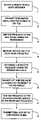
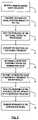
- FIG. 5illustrates a method for self-aligning a transmission signal between a portable transceiving device and a base station transceiving device.
- a remote vehicle entry operationis initiated.
- the remote vehicle entry operationmay include actuating a respective button on a RKE fob for unlocking a vehicle door.
- other vehicle-based RF applicationsmay include engine start/stop operations, or tire pressure monitoring.
- a confirmation signalis sent from the RKE module to the RKE fob providing status of the requested vehicle entry operation.
- a portion of the RF signal transmittedincludes a RF test signal.
- the frequency of the transmissionis varied over a plurality of discrete frequencies during the transmission of the test signal.
- step 34the RSSI value of each discrete frequency is measured.
- step 35the controller of the RKE fob determines which respective frequency produces a maximum RSSI value.
- step 36the optimum RSSI value at the respective frequency is transmitted to the RKE module.
- step 37the RKE module is tuned to the respective frequency producing the maximum RSSI value.
- the optimum transmitting frequency along with an identification code of the RKE fobis stored in the memory of the RKE module. This allows the RKE module to identify the optimum transmitting frequency for a respective RKE fob if more than one RKE fob is used.
- step 38the remainder of the confirmation message is transmitted by the RKE module to the RKE fob using the respective frequency having the optimum RSSI value.
Landscapes
- Engineering & Computer Science (AREA)
- Computer Networks & Wireless Communication (AREA)
- Signal Processing (AREA)
- Quality & Reliability (AREA)
- Physics & Mathematics (AREA)
- Electromagnetism (AREA)
- Lock And Its Accessories (AREA)
Abstract
Description
Claims (17)
Priority Applications (4)
| Application Number | Priority Date | Filing Date | Title |
|---|---|---|---|
| US11/011,364US7580696B2 (en) | 2004-12-14 | 2004-12-14 | Self-aligning vehicular transmitter system |
| DE102005059226ADE102005059226B4 (en) | 2004-12-14 | 2005-12-12 | Automatically balancing transmission system for vehicles |
| GB0525266AGB2421338B (en) | 2004-12-14 | 2005-12-13 | Self-aligning vehicular transmitter system |
| US12/545,568US7986960B2 (en) | 2004-12-14 | 2009-08-21 | Self-aligning vehicular transmitter system |
Applications Claiming Priority (1)
| Application Number | Priority Date | Filing Date | Title |
|---|---|---|---|
| US11/011,364US7580696B2 (en) | 2004-12-14 | 2004-12-14 | Self-aligning vehicular transmitter system |
Related Child Applications (1)
| Application Number | Title | Priority Date | Filing Date |
|---|---|---|---|
| US12/545,568ContinuationUS7986960B2 (en) | 2004-12-14 | 2009-08-21 | Self-aligning vehicular transmitter system |
Publications (2)
| Publication Number | Publication Date |
|---|---|
| US20060125599A1 US20060125599A1 (en) | 2006-06-15 |
| US7580696B2true US7580696B2 (en) | 2009-08-25 |
Family
ID=35735965
Family Applications (2)
| Application Number | Title | Priority Date | Filing Date |
|---|---|---|---|
| US11/011,364Expired - Fee RelatedUS7580696B2 (en) | 2004-12-14 | 2004-12-14 | Self-aligning vehicular transmitter system |
| US12/545,568Expired - Fee RelatedUS7986960B2 (en) | 2004-12-14 | 2009-08-21 | Self-aligning vehicular transmitter system |
Family Applications After (1)
| Application Number | Title | Priority Date | Filing Date |
|---|---|---|---|
| US12/545,568Expired - Fee RelatedUS7986960B2 (en) | 2004-12-14 | 2009-08-21 | Self-aligning vehicular transmitter system |
Country Status (3)
| Country | Link |
|---|---|
| US (2) | US7580696B2 (en) |
| DE (1) | DE102005059226B4 (en) |
| GB (1) | GB2421338B (en) |
Cited By (5)
| Publication number | Priority date | Publication date | Assignee | Title |
|---|---|---|---|---|
| US20060143338A1 (en)* | 2004-12-29 | 2006-06-29 | Hunsaker Mikal C | Autodetection of a PCI express device operating at a wireless RF mitigation frequency |
| US20080151758A1 (en)* | 2006-12-22 | 2008-06-26 | Disney Enterprises, Inc. | Optimization of data delivery in mobile networks |
| US20090149170A1 (en)* | 2005-10-21 | 2009-06-11 | Muhammad Ali Kazmi | Apparatus and method for measurement reporting in a cellular telecommunications system |
| US20100148986A1 (en)* | 2007-03-06 | 2010-06-17 | Markus Aunkofer | Controller for wireless communication with a peripheral unit |
| US20110015809A1 (en)* | 2007-03-20 | 2011-01-20 | Ford Global Technologies, Llc | Device and Method for Wireless Vehicle Communication |
Families Citing this family (17)
| Publication number | Priority date | Publication date | Assignee | Title |
|---|---|---|---|---|
| JP4963006B2 (en)* | 2002-09-09 | 2012-06-27 | Ntn株式会社 | Wireless sensor system and wheel bearing device with wireless sensor |
| US20080309457A1 (en)* | 2005-03-02 | 2008-12-18 | Magnadyne Corporation | Power-save for passive and two-way transmitters |
| US8970363B2 (en) | 2006-09-14 | 2015-03-03 | Crown Equipment Corporation | Wrist/arm/hand mounted device for remotely controlling a materials handling vehicle |
| WO2008039649A2 (en) | 2006-09-14 | 2008-04-03 | Crown Equipment Corporation | Systems and methods of remotely controlling a materials handling vehicle |
| US8872616B2 (en)* | 2006-09-28 | 2014-10-28 | Lear Corporation | System and method for remote activation with interleaved modulation protocol |
| US9262878B1 (en) | 2006-09-28 | 2016-02-16 | Lear Corporation | System and method for one-way remote activation with adaptive protocol |
| US9047716B1 (en) | 2006-09-28 | 2015-06-02 | Lear Corporation | System and method for two-way remote activation with adaptive protocol |
| US7944340B1 (en)* | 2006-09-28 | 2011-05-17 | Lear Corporation | System and method for two-way remote activation with adaptive protocol |
| ATE460322T1 (en)* | 2007-07-05 | 2010-03-15 | Magneti Marelli Spa | METHOD FOR CONTROLLING A VEHICLE EQUIPPED WITH A MECHANICAL SERVO TRANSMISSION |
| DE102008012882B4 (en)* | 2008-03-06 | 2020-07-23 | Continental Automotive France | Electrical circuit for an access control and for an immobilizer of a vehicle and method for measuring an antenna driver |
| US9522817B2 (en) | 2008-12-04 | 2016-12-20 | Crown Equipment Corporation | Sensor configuration for a materials handling vehicle |
| US8954011B2 (en)* | 2010-02-19 | 2015-02-10 | Broadcom Corporation | Method and system for a wireless integrated test and measurement device |
| KR101394036B1 (en)* | 2012-09-28 | 2014-05-12 | 현대자동차 주식회사 | Remote control system and method for vehicle |
| US9379828B2 (en)* | 2014-11-07 | 2016-06-28 | Ford Global Technologies, Llc | Multiple transceiver and antenna verification system |
| MX2021009158A (en) | 2019-02-01 | 2021-09-10 | Crown Equip Corp | Pairing a remote control device to a vehicle. |
| US11641121B2 (en) | 2019-02-01 | 2023-05-02 | Crown Equipment Corporation | On-board charging station for a remote control device |
| MX2023001754A (en) | 2020-08-11 | 2023-03-07 | Crown Equip Corp | REMOTE CONTROL DEVICE. |
Citations (15)
| Publication number | Priority date | Publication date | Assignee | Title |
|---|---|---|---|---|
| US4888763A (en) | 1988-03-11 | 1989-12-19 | Codenoll Technology Corporation | Method and apparatus for detecting the collision of data packets utilizing a preassigned transceiver code in the preamble |
| US5844517A (en)* | 1996-02-02 | 1998-12-01 | Trw Inc. | Portable transceiver for keyless vehicle entry system having phase delay |
| JP2000054698A (en) | 1998-08-10 | 2000-02-22 | Denso Corp | Key-less entry control system |
| JP2000054700A (en) | 1998-08-10 | 2000-02-22 | Nippon Soken Inc | Key-less entry receiver |
| US6091343A (en)* | 1997-12-18 | 2000-07-18 | Prince Corporation | Trainable RF transmitter having expanded learning capabilities |
| US6236333B1 (en)* | 1998-06-17 | 2001-05-22 | Lear Automotive Dearborn, Inc. | Passive remote keyless entry system |
| WO2002007993A2 (en) | 2000-07-26 | 2002-01-31 | Bridgestone/Firestone, Inc. | Electronic tire management system |
| JP2003244013A (en) | 2002-02-14 | 2003-08-29 | Nippon Seiki Co Ltd | Transmitter-receiver |
| US6625459B1 (en) | 1999-06-04 | 2003-09-23 | Broadcom Corporation | Method and apparatus for efficient determination of channel estimate and baud frequency offset estimate |
| US20040037365A1 (en)* | 2002-08-21 | 2004-02-26 | King Ronald O. | Remote transmitter system and method |
| US6710701B2 (en)* | 1998-04-22 | 2004-03-23 | Gilbarco Inc. | Rfid tag location using tag or host interaction record |
| US20040183714A1 (en) | 2003-03-03 | 2004-09-23 | Shuji Yamashita | Vehicular remote control system |
| US6801134B1 (en) | 2000-03-02 | 2004-10-05 | Trw Inc. | System and method for automatic function operation with controlled distance communication having vehicle-based frequency selection |
| US7190253B2 (en)* | 2001-11-19 | 2007-03-13 | Denso Corporation | Door control system and method for vehicles |
| US7292134B2 (en)* | 2004-11-01 | 2007-11-06 | Lear Corporation | Selectable range remote entry system |
Family Cites Families (1)
| Publication number | Priority date | Publication date | Assignee | Title |
|---|---|---|---|---|
| DE10059868A1 (en)* | 2000-11-30 | 2002-06-27 | Horst Ziegler | Process for the transmission of data |
- 2004
- 2004-12-14USUS11/011,364patent/US7580696B2/ennot_activeExpired - Fee Related
- 2005
- 2005-12-12DEDE102005059226Apatent/DE102005059226B4/ennot_activeExpired - Fee Related
- 2005-12-13GBGB0525266Apatent/GB2421338B/ennot_activeExpired - Fee Related
- 2009
- 2009-08-21USUS12/545,568patent/US7986960B2/ennot_activeExpired - Fee Related
Patent Citations (16)
| Publication number | Priority date | Publication date | Assignee | Title |
|---|---|---|---|---|
| US4888763A (en) | 1988-03-11 | 1989-12-19 | Codenoll Technology Corporation | Method and apparatus for detecting the collision of data packets utilizing a preassigned transceiver code in the preamble |
| US5844517A (en)* | 1996-02-02 | 1998-12-01 | Trw Inc. | Portable transceiver for keyless vehicle entry system having phase delay |
| US6091343A (en)* | 1997-12-18 | 2000-07-18 | Prince Corporation | Trainable RF transmitter having expanded learning capabilities |
| US6710701B2 (en)* | 1998-04-22 | 2004-03-23 | Gilbarco Inc. | Rfid tag location using tag or host interaction record |
| US6236333B1 (en)* | 1998-06-17 | 2001-05-22 | Lear Automotive Dearborn, Inc. | Passive remote keyless entry system |
| JP2000054698A (en) | 1998-08-10 | 2000-02-22 | Denso Corp | Key-less entry control system |
| JP2000054700A (en) | 1998-08-10 | 2000-02-22 | Nippon Soken Inc | Key-less entry receiver |
| US6625459B1 (en) | 1999-06-04 | 2003-09-23 | Broadcom Corporation | Method and apparatus for efficient determination of channel estimate and baud frequency offset estimate |
| US6801134B1 (en) | 2000-03-02 | 2004-10-05 | Trw Inc. | System and method for automatic function operation with controlled distance communication having vehicle-based frequency selection |
| WO2002007993A2 (en) | 2000-07-26 | 2002-01-31 | Bridgestone/Firestone, Inc. | Electronic tire management system |
| US7190253B2 (en)* | 2001-11-19 | 2007-03-13 | Denso Corporation | Door control system and method for vehicles |
| JP2003244013A (en) | 2002-02-14 | 2003-08-29 | Nippon Seiki Co Ltd | Transmitter-receiver |
| US20040037365A1 (en)* | 2002-08-21 | 2004-02-26 | King Ronald O. | Remote transmitter system and method |
| DE10304463A1 (en) | 2002-08-21 | 2004-03-04 | Lear Corp., Southfield | Remote transmission system and method |
| US20040183714A1 (en) | 2003-03-03 | 2004-09-23 | Shuji Yamashita | Vehicular remote control system |
| US7292134B2 (en)* | 2004-11-01 | 2007-11-06 | Lear Corporation | Selectable range remote entry system |
Cited By (8)
| Publication number | Priority date | Publication date | Assignee | Title |
|---|---|---|---|---|
| US20060143338A1 (en)* | 2004-12-29 | 2006-06-29 | Hunsaker Mikal C | Autodetection of a PCI express device operating at a wireless RF mitigation frequency |
| US8041844B2 (en)* | 2004-12-29 | 2011-10-18 | Intel Corporation | Autodetection of a PCI express device operating at a wireless RF mitigation frequency |
| US20090149170A1 (en)* | 2005-10-21 | 2009-06-11 | Muhammad Ali Kazmi | Apparatus and method for measurement reporting in a cellular telecommunications system |
| US20080151758A1 (en)* | 2006-12-22 | 2008-06-26 | Disney Enterprises, Inc. | Optimization of data delivery in mobile networks |
| US8744470B2 (en) | 2006-12-22 | 2014-06-03 | Disney Enterprises, Inc. | Optimization of data delivery in mobile networks |
| US20100148986A1 (en)* | 2007-03-06 | 2010-06-17 | Markus Aunkofer | Controller for wireless communication with a peripheral unit |
| US8841993B2 (en)* | 2007-03-06 | 2014-09-23 | Continental Automotive Gmbh | Controller for wireless communication with a peripheral unit |
| US20110015809A1 (en)* | 2007-03-20 | 2011-01-20 | Ford Global Technologies, Llc | Device and Method for Wireless Vehicle Communication |
Also Published As
| Publication number | Publication date |
|---|---|
| GB0525266D0 (en) | 2006-01-18 |
| US20090309753A1 (en) | 2009-12-17 |
| US20060125599A1 (en) | 2006-06-15 |
| US7986960B2 (en) | 2011-07-26 |
| GB2421338B (en) | 2007-01-24 |
| DE102005059226A1 (en) | 2006-07-13 |
| DE102005059226B4 (en) | 2011-05-05 |
| GB2421338A (en) | 2006-06-21 |
Similar Documents
| Publication | Publication Date | Title |
|---|---|---|
| US7986960B2 (en) | Self-aligning vehicular transmitter system | |
| US10737659B2 (en) | Protocols for remote vehicle access systems | |
| US20080174446A1 (en) | Multi-channel passive vehicle activation system | |
| US10131319B2 (en) | Multi-range vehicle access systems | |
| US7944340B1 (en) | System and method for two-way remote activation with adaptive protocol | |
| US7859389B2 (en) | Transmitter modulation switching | |
| US7046119B2 (en) | Vehicle independent passive entry system | |
| KR100693971B1 (en) | Wireless communication system and wireless communication device | |
| US6906612B2 (en) | System and method for vehicle passive entry having inside/outside detection | |
| USRE45166E1 (en) | Remote keyless entry system with two-way long range communication | |
| US8102241B2 (en) | Vehicle control system | |
| US7647031B2 (en) | Vehicle receiver system in which a single receiver circuit is controlled to receive signals transmitted from a plurality of remote devices having respectively different transmission frequencies | |
| US20080088409A1 (en) | Vehicle control system | |
| US7230577B2 (en) | Wireless terminal position detecting device and method | |
| US20080186131A1 (en) | Certification system and method | |
| US9262878B1 (en) | System and method for one-way remote activation with adaptive protocol | |
| JP2012067499A (en) | Radio communication system | |
| CN101197068A (en) | Frequency selection in system for remote activation of vehicle functions | |
| US20070026898A1 (en) | System and method for use in wireless communication employing multiple antennas | |
| US7064457B2 (en) | Recognition device intended to order the unlocking of a vehicle door and/or to authorize the starting of a vehicle | |
| US20030085620A1 (en) | Antitheft system, method for operating an antitheft system and components of an antitheft system | |
| US20230092743A1 (en) | Method for ultra high frequency continuous communication with and location of a portable device for "hands-free" access to a motor vehicle | |
| JP2003018664A (en) | Remote keyless entry |
Legal Events
| Date | Code | Title | Description |
|---|---|---|---|
| AS | Assignment | Owner name:LEAR CORPORATION, MICHIGAN Free format text:ASSIGNMENT OF ASSIGNORS INTEREST;ASSIGNORS:GHABRA, RIAD;LUO, YI;TANG, QINGFENG;REEL/FRAME:016086/0217 Effective date:20041213 | |
| AS | Assignment | Owner name:JPMORGAN CHASE BANK, N.A., AS ADMINISTRATIVE AGENT Free format text:GRANT OF FIRST LIEN SECURITY INTEREST IN PATENT RIGHTS;ASSIGNOR:LEAR CORPORATION;REEL/FRAME:023519/0267 Effective date:20091109 Owner name:JPMORGAN CHASE BANK, N.A., AS ADMINISTRATIVE AGENT Free format text:GRANT OF SECOND LIEN SECURITY INTEREST IN PATENT RIGHTS;ASSIGNOR:LEAR CORPORATION;REEL/FRAME:023519/0626 Effective date:20091109 | |
| CC | Certificate of correction | ||
| FPAY | Fee payment | Year of fee payment:4 | |
| AS | Assignment | Owner name:JPMORGAN CAHSE BANK, N.A., AS AGENT, ILLINOIS Free format text:SECURITY INTEREST;ASSIGNOR:LEAR CORPORATION;REEL/FRAME:030076/0016 Effective date:20130130 Owner name:JPMORGAN CHASE BANK, N.A., AS AGENT, ILLINOIS Free format text:SECURITY INTEREST;ASSIGNOR:LEAR CORPORATION;REEL/FRAME:030076/0016 Effective date:20130130 | |
| AS | Assignment | Owner name:LEAR CORPORATION, MICHIGAN Free format text:RELEASE BY SECURED PARTY;ASSIGNOR:JPMORGAN CHASE BANK, N.A.;REEL/FRAME:032770/0843 Effective date:20100830 | |
| AS | Assignment | Owner name:LEAR CORPORATION, MICHIGAN Free format text:RELEASE BY SECURED PARTY;ASSIGNOR:JPMORGAN CHASE BANK, N.A., AS AGENT;REEL/FRAME:037701/0251 Effective date:20160104 Owner name:LEAR CORPORATION, MICHIGAN Free format text:RELEASE BY SECURED PARTY;ASSIGNOR:JPMORGAN CHASE BANK, N.A., AS AGENT;REEL/FRAME:037701/0180 Effective date:20160104 Owner name:LEAR CORPORATION, MICHIGAN Free format text:RELEASE BY SECURED PARTY;ASSIGNOR:JPMORGAN CHASE BANK, N.A., AS AGENT;REEL/FRAME:037701/0340 Effective date:20160104 | |
| AS | Assignment | Owner name:LEAR CORPORATION, MICHIGAN Free format text:RELEASE BY SECURED PARTY;ASSIGNOR:JPMORGAN CHASE BANK, N.A., AS AGENT;REEL/FRAME:037702/0911 Effective date:20160104 | |
| REMI | Maintenance fee reminder mailed | ||
| LAPS | Lapse for failure to pay maintenance fees | Free format text:PATENT EXPIRED FOR FAILURE TO PAY MAINTENANCE FEES (ORIGINAL EVENT CODE: EXP.) | |
| STCH | Information on status: patent discontinuation | Free format text:PATENT EXPIRED DUE TO NONPAYMENT OF MAINTENANCE FEES UNDER 37 CFR 1.362 | |
| FP | Lapsed due to failure to pay maintenance fee | Effective date:20170825 |