US7578907B2 - Valve system for unheading a coke drum - Google Patents
Valve system for unheading a coke drumDownload PDFInfo
- Publication number
- US7578907B2 US7578907B2US11/396,982US39698206AUS7578907B2US 7578907 B2US7578907 B2US 7578907B2US 39698206 AUS39698206 AUS 39698206AUS 7578907 B2US7578907 B2US 7578907B2
- Authority
- US
- United States
- Prior art keywords
- valve
- coke drum
- coke
- seat
- valve closure
- Prior art date
- Legal status (The legal status is an assumption and is not a legal conclusion. Google has not performed a legal analysis and makes no representation as to the accuracy of the status listed.)
- Expired - Lifetime, expires
Links
- 239000000571cokeSubstances0.000titleclaimsabstractdescription321
- 229910052751metalInorganic materials0.000claimsdescription39
- 239000002184metalSubstances0.000claimsdescription39
- 230000003068static effectEffects0.000claimsdescription36
- 239000000463materialSubstances0.000claimsdescription21
- 230000009977dual effectEffects0.000claimsdescription14
- 238000010926purgeMethods0.000claimsdescription14
- 239000007787solidSubstances0.000claimsdescription14
- 238000002955isolationMethods0.000claimsdescription10
- 238000000034methodMethods0.000abstractdescription82
- 230000008569processEffects0.000abstractdescription62
- 230000006870functionEffects0.000abstractdescription44
- 238000004519manufacturing processMethods0.000abstractdescription34
- 239000006227byproductSubstances0.000abstractdescription20
- 239000003208petroleumSubstances0.000abstractdescription18
- 230000008901benefitEffects0.000abstractdescription16
- 238000005235decokingMethods0.000abstractdescription12
- 238000013461designMethods0.000abstractdescription9
- 238000004939cokingMethods0.000description37
- 238000007667floatingMethods0.000description26
- 230000003111delayed effectEffects0.000description18
- XLYOFNOQVPJJNP-UHFFFAOYSA-NwaterSubstancesOXLYOFNOQVPJJNP-UHFFFAOYSA-N0.000description15
- 238000012423maintenanceMethods0.000description12
- 210000003660reticulumAnatomy0.000description12
- 238000007789sealingMethods0.000description11
- 230000000712assemblyEffects0.000description10
- 238000000429assemblyMethods0.000description10
- 238000005516engineering processMethods0.000description8
- 238000010168coupling processMethods0.000description7
- 238000005859coupling reactionMethods0.000description7
- 239000007788liquidSubstances0.000description7
- 230000008878couplingEffects0.000description6
- 230000000670limiting effectEffects0.000description6
- 230000007704transitionEffects0.000description6
- 238000001816coolingMethods0.000description5
- 230000010355oscillationEffects0.000description5
- 238000010008shearingMethods0.000description5
- 238000006243chemical reactionMethods0.000description4
- 238000011049fillingMethods0.000description4
- 230000006872improvementEffects0.000description4
- 230000007246mechanismEffects0.000description4
- 239000003921oilSubstances0.000description4
- 239000000047productSubstances0.000description4
- 238000009835boilingMethods0.000description3
- 238000004140cleaningMethods0.000description3
- 238000010586diagramMethods0.000description3
- 238000011010flushing procedureMethods0.000description3
- 239000007789gasSubstances0.000description3
- 239000000126substanceSubstances0.000description3
- 238000004227thermal crackingMethods0.000description3
- 230000009471actionEffects0.000description2
- 238000013459approachMethods0.000description2
- 238000010924continuous productionMethods0.000description2
- 239000000498cooling waterSubstances0.000description2
- 238000005336crackingMethods0.000description2
- 238000005520cutting processMethods0.000description2
- 230000007812deficiencyEffects0.000description2
- 230000000694effectsEffects0.000description2
- 239000000446fuelSubstances0.000description2
- 229930195733hydrocarbonNatural products0.000description2
- 150000002430hydrocarbonsChemical class0.000description2
- 230000007774longtermEffects0.000description2
- 238000012986modificationMethods0.000description2
- 230000004048modificationEffects0.000description2
- 239000002245particleSubstances0.000description2
- 239000002006petroleum cokeSubstances0.000description2
- 238000010791quenchingMethods0.000description2
- 238000003860storageMethods0.000description2
- 238000012546transferMethods0.000description2
- 239000004215Carbon black (E152)Substances0.000description1
- 241001274197Scatophagus argusSpecies0.000description1
- 229910000831SteelInorganic materials0.000description1
- 206010053615Thermal burnDiseases0.000description1
- 229910052782aluminiumInorganic materials0.000description1
- XAGFODPZIPBFFR-UHFFFAOYSA-NaluminiumChemical compound[Al]XAGFODPZIPBFFR-UHFFFAOYSA-N0.000description1
- 238000004458analytical methodMethods0.000description1
- 230000004888barrier functionEffects0.000description1
- 230000015572biosynthetic processEffects0.000description1
- 230000036760body temperatureEffects0.000description1
- 239000003575carbonaceous materialSubstances0.000description1
- 230000002860competitive effectEffects0.000description1
- 238000010276constructionMethods0.000description1
- 230000007797corrosionEffects0.000description1
- 238000005260corrosionMethods0.000description1
- 239000010779crude oilSubstances0.000description1
- 230000034994deathEffects0.000description1
- 231100000517deathToxicity0.000description1
- 230000007423decreaseEffects0.000description1
- 238000009826distributionMethods0.000description1
- 238000005553drillingMethods0.000description1
- 230000005611electricityEffects0.000description1
- 230000007613environmental effectEffects0.000description1
- 239000012530fluidSubstances0.000description1
- 239000012634fragmentSubstances0.000description1
- 238000000227grindingMethods0.000description1
- 231100001261hazardousToxicity0.000description1
- 229910001026inconelInorganic materials0.000description1
- 238000003780insertionMethods0.000description1
- 230000037431insertionEffects0.000description1
- 238000011068loading methodMethods0.000description1
- 230000007257malfunctionEffects0.000description1
- 230000005012migrationEffects0.000description1
- 238000013508migrationMethods0.000description1
- 239000011331needle cokeSubstances0.000description1
- 229910052755nonmetalInorganic materials0.000description1
- 230000001473noxious effectEffects0.000description1
- 238000012856packingMethods0.000description1
- 230000036961partial effectEffects0.000description1
- 239000003348petrochemical agentSubstances0.000description1
- 238000005498polishingMethods0.000description1
- 238000006116polymerization reactionMethods0.000description1
- 238000002360preparation methodMethods0.000description1
- 238000012545processingMethods0.000description1
- 238000011084recoveryMethods0.000description1
- 230000002829reductive effectEffects0.000description1
- 238000007670refiningMethods0.000description1
- 230000001105regulatory effectEffects0.000description1
- 230000004044responseEffects0.000description1
- 230000000284resting effectEffects0.000description1
- 239000010959steelSubstances0.000description1
- 238000012360testing methodMethods0.000description1
- 238000009834vaporizationMethods0.000description1
- 230000008016vaporizationEffects0.000description1
- 238000013022ventingMethods0.000description1
- 125000000391vinyl groupChemical group[H]C([*])=C([H])[H]0.000description1
- 229920002554vinyl polymerPolymers0.000description1
- 238000010792warmingMethods0.000description1
Images


Classifications
- F—MECHANICAL ENGINEERING; LIGHTING; HEATING; WEAPONS; BLASTING
- F16—ENGINEERING ELEMENTS AND UNITS; GENERAL MEASURES FOR PRODUCING AND MAINTAINING EFFECTIVE FUNCTIONING OF MACHINES OR INSTALLATIONS; THERMAL INSULATION IN GENERAL
- F16K—VALVES; TAPS; COCKS; ACTUATING-FLOATS; DEVICES FOR VENTING OR AERATING
- F16K3/00—Gate valves or sliding valves, i.e. cut-off apparatus with closing members having a sliding movement along the seat for opening and closing
- F16K3/02—Gate valves or sliding valves, i.e. cut-off apparatus with closing members having a sliding movement along the seat for opening and closing with flat sealing faces; Packings therefor
- F16K3/16—Gate valves or sliding valves, i.e. cut-off apparatus with closing members having a sliding movement along the seat for opening and closing with flat sealing faces; Packings therefor with special arrangements for separating the sealing faces or for pressing them together
- F16K3/20—Gate valves or sliding valves, i.e. cut-off apparatus with closing members having a sliding movement along the seat for opening and closing with flat sealing faces; Packings therefor with special arrangements for separating the sealing faces or for pressing them together by movement of the seats
- F16K3/205—Gate valves or sliding valves, i.e. cut-off apparatus with closing members having a sliding movement along the seat for opening and closing with flat sealing faces; Packings therefor with special arrangements for separating the sealing faces or for pressing them together by movement of the seats by means of cams
- C—CHEMISTRY; METALLURGY
- C10—PETROLEUM, GAS OR COKE INDUSTRIES; TECHNICAL GASES CONTAINING CARBON MONOXIDE; FUELS; LUBRICANTS; PEAT
- C10B—DESTRUCTIVE DISTILLATION OF CARBONACEOUS MATERIALS FOR PRODUCTION OF GAS, COKE, TAR, OR SIMILAR MATERIALS
- C10B25/00—Doors or closures for coke ovens
- C10B25/02—Doors; Door frames
- C10B25/08—Closing and opening the doors
- C10B25/10—Closing and opening the doors for ovens with vertical chambers
- F—MECHANICAL ENGINEERING; LIGHTING; HEATING; WEAPONS; BLASTING
- F16—ENGINEERING ELEMENTS AND UNITS; GENERAL MEASURES FOR PRODUCING AND MAINTAINING EFFECTIVE FUNCTIONING OF MACHINES OR INSTALLATIONS; THERMAL INSULATION IN GENERAL
- F16K—VALVES; TAPS; COCKS; ACTUATING-FLOATS; DEVICES FOR VENTING OR AERATING
- F16K3/00—Gate valves or sliding valves, i.e. cut-off apparatus with closing members having a sliding movement along the seat for opening and closing
- F16K3/02—Gate valves or sliding valves, i.e. cut-off apparatus with closing members having a sliding movement along the seat for opening and closing with flat sealing faces; Packings therefor
- F16K3/12—Gate valves or sliding valves, i.e. cut-off apparatus with closing members having a sliding movement along the seat for opening and closing with flat sealing faces; Packings therefor with wedge-shaped arrangements of sealing faces
- F16K3/14—Gate valves or sliding valves, i.e. cut-off apparatus with closing members having a sliding movement along the seat for opening and closing with flat sealing faces; Packings therefor with wedge-shaped arrangements of sealing faces with special arrangements for separating the sealing faces or for pressing them together
Definitions
- the present inventionrelates to the devices and systems used to de-head or unhead a vessel containing a fluid, distillate, or unconsolidated debris byproduct produced from a manufacturing process, such as the several types of coke produced from a petroleum refinery process, as well as to the several methods employed for unheading a vessel utilizing such devices or systems.
- the present inventionrelates to various unheading valves, and associated methods, namely various de-header valves that may be coupled to a coke drum, particularly at its top and/or bottom openings, wherein the valve functions to safely, effectively, and efficiently de-head or unhead the coke drum following the manufacture of coke, or other byproducts, and to facilitate the removal of coke during the decoking process.
- Coke drumsare usually in operation in pairs so that when one coke drum is finished being filled with the byproduct or residual material via a feed, the feed may be directed to an empty drum so that the filled drum may be cooled and the byproduct purged from the coke drum.
- decokingThe process of purging coke from a coke drum in known as decoking. This allows the refinery process to operate in a cyclical, continuous manner, without undue interruption.
- the coke drumis steam purged and cooled with quench water.
- the coke drumis then drained of water and vented to atmospheric pressure, after which the top and bottom flanges are removed. Removing the top and bottom flanges effectively functions to de-head the coke drum. Stated another way, removal of the flanges effectively removes the coke head that formed during the manufacturing process that is adjacent the flanges.
- the coke remaining within the coke drumis removed (typically by water cutting the coke from the drum) and emptied into a catch basin, typically a rail car. Once the coke is removed, the heads are replaced and the coke drum is prepared to repeat the cycle.
- U.S. Pat. Nos. 4,726,109 to Malsbury et al. and 4,960,358 to DiGiacomo et al.describe a remote unheading device for coking drums.
- the deviceincludes a head unit for attachment to a lower flange of a coking drum and a plurality of swing bolts which are disconnected by remotely operated de-tensioning equipment.
- a platform devicelowers the head unit, moves it laterally to one side and tips it for cleaning.
- a chute attached to the framecan be raised into engagement with the coking drum lower flange for removal of coke from the drum.
- U.S. Pat. No. 5,098,524 to Antalfy et al. filed on Dec. 10, 1990discloses a coke drum unheading device having a pivoting actuator system operable from a location remote from a drum outlet.
- the actuatoris adapted to move a drum head between closed and open positions and to retain the drum head in a closed position under a load.
- U.S. Pat. No. 5,500,094 to Fruchtbaumprovides a coke drum unheading device that retracts and tilts the bottom head incrementally so that falling debris such as shot coke can be caught by a chute. Following disposal of the loose debris, the head can be withdrawn from the area of the drum for maintenance.
- the inventionprovides an unheading device for removing a bottom head from a flange on a lower end of a coke drum.
- An unheading caris horizontally movable into and from position below the bottom head.
- a vertically adjustable bottom head support memberis mounted on the car.
- a bearing plateis pivotally mounted at an upper end of the support member for engaging a lower surface of the bottom head.
- a retractable armhas first and second sections hingedly connected at one end and having respective opposite ends secured to the bearing plate and the support member for pivoting the bearing plate and bottom head supported thereon with respect to horizontal, preferably to tilt the head towards an adjacent chute.
- U.S. Pat. No. 5,581,864 to Rabetdiscloses an apparatus and method enabling removal of the drum head of a coke drum, which comprises an apparatus remotely placing a carriage under the drum head and the carriage is adapted to remotely engage the drum head, tightly support the head against the drum while workers are in the area, and to lower the head and carry it away.
- a safety featureis also included and disclosed, wherein the carriage is normally supported by springs which, in the event of excessive loads, automatically transfers the load carrier to an overhead beam designed to carry any excessive loads.
- each of these prior art devicesshare common deficiencies in that they are incapable of providing simple, efficient, and safe solutions to the de-heading of a coke drum.
- each of the assemblies or devicesrequire that the head or flange unit be completely removed from the adjacent or matching flange portion of the coke drum after each coking cycle and prior to the purging of the coke from the coke drum. This creates an extreme hazard to workers and provides an inefficient and time consuming procedure.
- the requirement to remove the flange or head unitincreases the chance for accident, while at the same time increases human involvement as the head unit must be properly secured to the coke drum each operating cycle, despite the automation involved.
- coke drum de-headingis the systems and methods currently employed for de-heading a coke drum or similar vessel. Whether coke drum de-heading is done entirely manually, or by any one of the above discussed prior art limited automation or semi-automated systems and devices that are currently available, there is still a significant physical human on component required in the process, primarily due to the systems and methods utilized.
- the present inventionseeks to provide more efficient, cost-effective, and safe coke drum unheading devices and systems, as well as more efficient, cost-effective, and safe methods for unheading a coke drum or other similar vessel.
- Some embodiments of the present inventionfeature a coke drum de-header system comprising: (a) a coke drum having at least one port therein, said coke drum receiving byproduct material from a manufacturing system and process; (b) a de-header valve removably coupled to the coke drum for regulating the port of the coke drum and for allowing repeated de-heading and re-heading of the coke drum, said de-header valve comprising (1) a main body having an orifice dimensioned to align with the port of the coke drum when the de-header valve is coupled thereto; (2) a valve closure operably supported by the main body, wherein the valve closure is capable of being actuated to oscillate between an open and closed position with respect to the orifice of the de-header valve and the port of the coke drum; (3) means for supporting the valve closure; (c) a continuously maintained metal to metal contact seal between the valve closure and the means for supporting the valve closure that contributes to valve isolation, wherein the contact seal functions to shear any co
- the de-header valveis removably coupled to and seals against the flanged portion of a coke drum and over its port much the same way a conventional flange or head unit would be attached.
- the de-header valveis equipped with a valve closure that regulates the closing and opening of the coke drum, or rather regulates the opening and closing of the coke drum port and its associated throughput.
- the de-header valve and coke drumare prepared to receive the byproduct feed from the refinery process used to manufacture coke.
- the de-header valveAs the coke drum is being filled during one stage of a decoking process, the de-header valve, and particularly the valve closure, is actuated and positioned in a closed position, wherein a seal is formed between the valve closure and the means for supporting the valve closure.
- the valve closureis again actuated causing it to transition from a closed position to an open or semi-opened position. This opening action functions to shear any coke or other debris that accumulated on the valve closure or at or near the port of the coke drum, thus effectively de-heading the coke drum.
- Shearingoccurs because of the continuously maintained metal to metal contact between the valve closure and the means for supporting the valve closure. As the valve closure is caused to move, its metal surface slides about the metal surface of the means for supporting the valve closure, thus shearing the coke from and otherwise breaking its connection or attachment with the valve closure. Once the valve is opened and the coke drum de-headed, the coke may be removed from the coke drum using commonly known methods, techniques, and equipment.
- the de-header valve of the present inventionmay comprise one of several forms or types of valves.
- the de-header valvecomprise a valve-type selected from the group consisting of a plug valve, a ball or globe valve, a flexible wedge gate valve, a parallel slide gate valve, a solid wedge gate valve, and a sliding blind gate valve.
- Each of these valve-typesalthough functioning somewhat differently, are designed to comprise a continuously maintained metal to metal contact seal to create valve isolation and to provide the means for shearing the coke from the valve closure, thus de-heading the coke drum.
- the coke drum de-heading systemprovides unique advantages over prior art or prior related de-heading systems, namely the de-heading of a coke drum without having to physically remove bulky, dangerous flange or head units.
- An advantage of the present inventionis its ability to provide a simple, yet effective de-heading system comprising a de-header valve having a movable valve closure that oscillates or moves back and forth about the means for supporting the valve closure to de-head a coke drum and simplify the decoking process.
- Another advantage of the present inventionis the ability to de-head the coke drum without having to physically remove the head or flange unit, and to do so at a remote location with little or no manual requirements.
- the means for supporting the valve closurecomprises a seat support system.
- the seat support systemmay comprise any arrangement or configuration of seats, depending upon the type of valve, the needs of the system, system specifications, or any other contributing factors.
- the seat support systemcomprises an upper and lower seat existing on either side of the valve closure, wherein the upper seat and lower seat may be independent from one another.
- the upper and lower seatmay be comprised of either a static or dynamic nature, such that one may be static and the other dynamic, both dynamic, or both static.
- the seat support systemcomprises a single seat situated or disposed between the main body of the de-header valve and the valve closure.
- the single seatapplies a continuous force to the valve closure throughout its oscillation.
- the single seatmay be a floating or dynamic seat, or it may be a static seat, again depending upon the type of valve, the needs of the system, system specifications, or any other contributing factors.
- the biasing necessary to maintain bug term sealingis provided by the gate itself.
- Several gatesare biased against the seat to provide the same contact that would occur if the seat were biased toward the gate.
- the seat support systemadvantageously provides a floating seat concept to the de-header valve using at least one dynamic, live loaded seat.
- This floating dynamic, live loaded seatis continuously loaded against the valve closure to create a biased relationship between the seat(s) and the valve closure.
- the floating seat conceptis accomplished using one or a combination of biasing members, such as heavy coil springs arrayed at close centers around the perimeter of the seat ring; externally live loaded and sealed seat force applicators arrayed at quadrants around the floating seats; and/or a full perimeter flexible inconnel bellow seal spring placed between the floating seat and the seat retaining ring.
- a floating or dynamic seatprovides many advantages, a primary one being that the seat support system and the valve closure are able to flex and distort in response to the rigorous and changing pressures and forces induced thereon during the coke manufacturing process and filling of the coke drum.
- means for supporting the valve closurecomprises the main body itself.
- no seatsare required as various structural modifications can be made to the main body to support the valve closure.
- a seatmay be used to support the valve closure on one side and the main body on the other.
- the continuously maintained contact sealcomprises a sealing system that seals directly against the valve closure.
- Thismay be a point to point sealing system.
- the sealpreferably consists of or is a result of the metal to metal seating between the valve closure and the means for supporting the valve closure, such as upper and lower seats.
- an identifiable and calculated forceis created or induced between these two components and maintained in a continuous manner as the valve closure oscillates between its open and closed positions.
- the amount of force required to properly seal the valve closure and the means for supporting the valve closureis provided via a seat support system, wherein one or more of the seats may be a floating or dynamic seat coupled to a seat adjustment mechanism designed to control the amount of force exerted on the valve closure through or by the seat.
- the present invention coke drum de-header systemfurther comprises a steam purge system.
- the systemutilizes pressure valves and steam purge inlet valves, as well as emergency vent valves to monitor and control pressure within the system and to prevent inadvertent venting of the steam to atmosphere.
- the present invention coke drum de-header systemfurther comprises an internal coke containment system that provides or maintains total isolation of the coke within the system.
- the internal coke containment systemcomprises the metal to metal contact seal described herein, as well as a unique component configuration existing within the bonnets of the de-header valve.
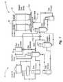
- FIG. 1illustrates, generally, an exemplary refinery process, wherein refinery byproducts are routed to a series of coke drums for the manufacture of coke, and wherein the coke drums are equipped with the de-header valves of the present invention
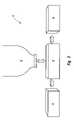
- FIG. 2illustrates a general diagram representative of any type of de-header valve as it connects to a coke drum and upper and lower bonnet within a coke drum de-heading system according to an exemplary operating environment of the present invention
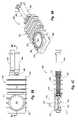
- FIG. 3-Aillustrates a perspective view of a wedge plug-type de-header valve according to one exemplary embodiment of the present invention
- FIG. 3-Billustrates a cut-away side view of the wedge plug-type de-header valve of FIG. 3-A ;
- FIG. 4-Aillustrates a perspective view of a rotary ball-type de-header valve according to one exemplary embodiment of the present invention
- FIG. 4-Billustrates a cut-away side view of the ball-type de-header valve of FIG. 4-A ;
- FIG. 5-Aillustrates a perspective view of an adjusting wedge gate-type de-header valve according to one exemplary embodiment of the present invention
- FIG. 5-Billustrates a top view of the adjusting wedge gate-type de-header valve of FIG. 5-A ;
- FIG. 5-Cillustrates a cut-away side view of the adjusting wedge gate-type de-header valve of FIG. 5-A ;
- FIG. 6-Aillustrates a perspective view of a flexible wedge gate-type de-header valve according to one exemplary embodiment of the present invention
- FIG. 6-Billustrates a top view of the flexible wedge gate-type de-header valve of FIG. 6-A ;
- FIG. 6-Cillustrates a cut-away side view of the flexible wedge gate-type de-header valve of FIG. 6-A ;
- FIG. 7-Aillustrates a perspective view of a parallel slide gate-type de-header valve according to one exemplary embodiment of the present invention
- FIG. 7-Billustrates a top view of the parallel slide gate-type de-header valve of FIG. 7-A ;
- FIG. 7-Cillustrates a cut-away side view of the parallel slide gate-type de-header valve of FIG. 7-A ;
- FIG. 8-Aillustrates a perspective view of a solid wedge gate-type de-header valve according to one exemplary embodiment of the present invention
- FIG. 8-Billustrates a top view of the solid wedge gate-type de-header valve of FIG. 8-A ;
- FIG. 8-Cillustrates a cut-away side view of the solid wedge gate-type de-header valve of FIG. 8-A ;
- FIG. 9-Aillustrates a perspective view of a sliding blind gate-type de-header valve according to one exemplary embodiment of the present invention
- FIG. 9-Billustrates a top view of the sliding blind gate-type de-header valve of FIG. 9-A ;
- FIG. 9-Cillustrates a cut-away side view of the sliding blind gate-type de-header valve of FIG. 9-A ;
- FIG. 10illustrates a globe-type de-header valve according to one exemplary embodiment of the present invention
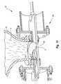
- FIG. 11illustrates a de-header valve in operation as attached to a coke drum
- FIG. 12illustrates a de-header valve in operation as attached to a coke drum.
- the first sectionpertains to and sets forth a general discussion of the delayed coking process, including the process and effects of de-heading a coke drum at the end of a coke manufacturing cycle.
- the second sectionpertains to and sets forth the coke drum de-heading system, including the variety of valves or valve-types that may be utilized in the coke drum de-heading system and within a delayed coking process, as well as the various methods for utilizing the system within a delayed coking or other similar environment. It is noted that these sections are not intended to be limiting in any way, but are simply provided as convenience to the reader.
- coke drumsIn the typical delayed coking process, high boiling petroleum residues are fed to one or more coke drums where they are thermally cracked into light products and a solid residue—petroleum coke.
- the coke drumsare typically large cylindrical vessels having a top head and a conical bottom portion fitted with a bottom head.
- the fundamental goal of cokingis the thermal cracking of very high boiling point petroleum residues into lighter fuel fractions.
- Cokeis a byproduct of the process. Delayed coking is an endothermic reaction with a furnace supplying the necessary heat to complete the coking reaction in a drum.
- delayed cokingis a thermal cracking process used in petroleum refineries to upgrade and convert petroleum residuum (or resid) into liquid and gas product streams leaving behind a solid concentrated carbon material, or coke.
- a fired heateris used in the process to reach thermal cracking temperatures, which range upwards of 1,000° F. With short residence time in the furnace, coking of the feed material is thereby “delayed” until it reaches large coking drums downstream of the heater.
- coke drumsIn normal operations, there are two coke drums so that when one is being filled, the other may be purged of the manufactured coke.
- These coke drumsare large structures that are approximately 25-30 meters in height and from 4 to 9 meters in diameter. They are equipped with a top blind flange closure or orifice that is typically about 1.5 meters in diameter, and a bottom blind flange orifice that is typically about 2 meters in diameter.
- cokeIn a typical petroleum refinery process, several different physical structures of petroleum coke may be produced. These are namely, shot coke, sponge coke, and/or needle coke (hereinafter collectively referred to as “coke”), and are each distinguished by their physical structures and chemical properties. These physical structures and chemical properties also serve to determine the end use of the material.
- cokeshot coke, sponge coke, and/or needle coke
- Several usesare available for manufactured coke, some of which include fuel for burning, the ability to be calcined for use in the aluminum, chemical, or steel industries, or the ability to be gasified to produce steam, electricity, or gas feedstock for the petrochemicals industry.
- a delayed coker feedoriginates from the crude oil supplied to the refinery and travels through a series of process members and finally empties into one of the coke drums used to manufacture coke.
- a basic refinery flow diagramis presented as FIG. 1 , with two coke drums shown.
- the delayed coking processtypically comprises a batch-continuous process, which means that the process is ongoing or continuous as the feed stream coming from the furnace alternates filling between the two or more coke drums.
- the processis ongoing or continuous as the feed stream coming from the furnace alternates filling between the two or more coke drums.
- the otheris being stripped, cooled, decoked, and prepared to receive another batch.
- thishas proven to be an extremely time and labor intensive process, with each batch in the batch-continuous process talking approximately 12-20 hours to complete.
- hot oilor resid as it is commonly referred to, from the tube furnace is fed into one of the coke drums in the system.
- the oilis extremely hot and produces hot vapors that condense on the colder walls of the coke drum.
- a large amount of liquidruns down the sides of the drum into a boiling turbulent pool at the bottom.
- the hot resid and the condensing vaporscause the coke drum walls to heat. This naturally in turn, causes the resid to produce less and less of the condensing vapors, which ultimately causes the liquid at the bottom of the coke drum to start to heat up to coking temperatures.
- the decoking processis the process used to remove the coke from the drum upon completion of the coking process. Due to the shape of the coke drum, coke accumulates in the area near and attaches to the flanges or other members used to close off the opening of the coke drum during the manufacturing process. To decoke the drum, the flanges or members must first be removed or relocated. In the case of a flanged system, once full, the coke drum is vented to atmospheric pressure and the top flange (typically a 4-foot diameter flange) is unbolted and removed to enable placement of a hydraulic coke cutting apparatus.
- the top flangetypically a 4-foot diameter flange
- the bottom flange(typically a 7-foot-diameter flange) is unbolted and removed.
- This processis commonly known as “de-heading” because it removes or breaks free the head of coke that accumulates at the surface of the flange.
- de-headinga coke drum can be a very dangerous procedure, namely because of the size of the flanges, the high environmental temperatures within the drum, the potential of loose coke to fall, and other reasons.
- the cokeis removed from the drum by drilling a pilot hole from top to bottom of the coke bed using high pressure water jets.
- the main body of coke left in the coke drumis cut into fragments which fall out the bottom and into a collection bin, such as a bin on a rail cart, etc.
- the cokeis then dewatered, crushed and sent to coke storage or a loading facility.
- the present inventionis intended to cover both top and bottom de-heading systems, or rather the de-heading system of the present invention may be applicable and utilized on both the top and bottom openings of a coke drum, the following detailed description and preferred embodiments will be discussed in reference to a bottom de-heading system only.
- a coke drum bottom de-heading systemmay also be designed and used as a coke drum top de-heading system, and that the following discussion pertaining to the bottom de-heading system is limited to such.
- the present inventiondescribes a valve system and method for unheading or de-heading a coke drum following the manufacture of coke therein.
- the present inventionis especially adapted to be used in the coking process, the following discussion will relate specifically in this manufacturing area. It is foreseeable however, that the present invention may be adapted to be an integral part of other manufacturing processes producing various elements or by products other than coke, and such processes should thus be considered within the scope of this application.
- the present invention de-header system and de-header valvesmay be utilized within other critical service applications, such as inlet feed line isolation, blowdown isolation, fractionator isolation, and back warming.
- the systemis capable of automatic and repeated unheading (or de-heading) of a coke drum with little or no manual intervention required at or nearby the coke drum. Thus, safety and efficiency are both dramatically increased.
- the systemreduces the total de-heading to re-heading time to less than 10 minutes. Such a time is a drastic improvement over the times of prior art de-heading systems.
- the de-header valvemay be removably fixed or coupled directly to the coke drum flange, or to a transition spool above the de-header valve, as well as to a stationary coke chute below the device, which chute discharges directly into a collection bin or rail car.
- the systemhas the flexibility to allow safe drainage of coke and drum water through its outlet port and into the pit without any spillage onto the de-heading deck.
- the systemis designed and constructed in a way to ensure long term operation without clogging or being operationally obstructed by coke particles, chunks, resid, or any other foreign matter.
- the systemis designed to be able to demonstrate, with absolute certainty, at all times and at all local and remote locations that it is positively isolating.
- the systemis virtually maintenance free except for long term parts replacement during scheduled shutdowns. Thus there are virtually no maintenance costs beyond the scheduled maintenance times.
- the systemis capable of incorporating diagnostic capabilities that allow real time assessment and trending of the condition of sealing components during normal operations, in order to facilitate planned maintenance.
- the systemis easy to install as compared with other systems, and is capable of being serviced in the field or on-site.
- the systemis cost competitive with existing technology, yet significantly outperforms this technology in virtually every aspect.
- the de-header valve and systemfunctions to increase the throughput of the delayed coking system.
- the de-header systemmay be configured to allow drainage or water through the port, and drainage of water and coke through the port.
- the systemcomprises a simple mechanical design and is extremely simple to operate.
- the systemis totally enclosed from the top head of the coke drum to the receiving area or collection bin, thus no exposure to personnel, the unheading deck, or to plant equipment.
- all required safety interlocksare incorporated.
- operating costsare low. For instance, there are no head gaskets or feed line coupling gaskets to replace at each drum cycle; nor are there any feed line coupling or alignment systems to maintain; there is no water flushing required after each cycle; there is no disassembly, cleaning, and re-assembly required after each cycle; and there are no parts or tools that need replacing at each cycle.
- the de-header valve and systemcomprises a steam purged body that utilizes a diagnostics tool, that regulates body temperature, and that creates a barrier against coke migration.
- the de-header valvemay be quickly assembled and installed onto a coke drum and disassembled and uninstalled from a coke drum, and is re-buildable on-site during shutdowns.
- the systemcomprises a simple, redundant hydraulic design with one hydraulic power unit and one cylinder, and one supply and one return hydraulic line. Therefore, there is less exposure to possible leaks during commissioning and startup as well as less opportunity for accidental or inappropriate normal operation.
- the systemcomprises a positive mechanical lockout device in the form of a lockout pin, that may be incorporated during both open and closed positions of the valve.
- a compact hydraulic backup device for the open and close functionsis supplied with the system, or is easily installed at the site, without exposing personnel.
- coke drum inlet feed line coupling and alignment devicesare not required, therefore, there are no inlet line-coupling gaskets to replace or clean following each drum cycle, or exposure to personnel due to coupling misalignment and leakage.
- the systemcomprises a simple redundant hydraulic design as described above.
- the systemalso comprises one major moving part instead of multiple moving parts as found on existing devices and systems. This significantly increases the ease of operation, as well as the durability of the system because there is less that can go wrong or less moving parts that can malfunction.
- the isolation and containment of the cokeprovide a clean operating atmosphere that contributes to the durability and robust nature of the system.
- the systemcomprises a compact and basic operating control console that can be strategically located and installed with minimal effort and with all desired safety interlocks. Still further, the system comprises internal diagnostic capabilities that allow the operator to schedule maintenance to coincide with planned shutdown times. Still further, no water flushing of moving parts is required. Still further, the coke drum inlet feed line coupling and alignment devices are not required, thus there are no inlet line coupling gaskets to replace or clean after each cycle. Still further, minimum spare parts are required to be kept on hand, thus parts and storage costs can be reduced. Finally, the system can be configured to allow drainage of the drum water directly through the port on the coke drum.
- the systemis designed to be used on either the top or bottom ports of the coke drum. Moreover, the system is designed for use in other industries or for other critical use systems.
- FIG. 1depicts, generally, a petroleum manufacturing and refinery process 8 having several elements and systems present (identified, but not discussed).
- petroleum manufacturing and refinery process 8further comprises a coke drum de-heading system 10 that includes first and second delayed coke drums 18 and 22 , respectively, and de-header valves 14 - a and 14 - b attached thereto.
- coke drum de-heading system 10that includes first and second delayed coke drums 18 and 22 , respectively, and de-header valves 14 - a and 14 - b attached thereto.
- there are typically at least two coke drums in simultaneous operationso as to permit the ongoing manufacture and refinery of petroleum as well as its coke byproduct.
- first coke drum 18While first coke drum 18 is online and being filled via feed inlet 26 , second coke drum 22 is going through a decoking process to purge the manufactured coke contained therein. Thereafter, when first coke drum 18 has reached capacity, feed inlet 26 is switched to second coke drum 22 that has just previously been purged of its contents, whereby first coke drum 18 is primed for the decoking process where its contents will be purged.
- This cyclical processcommonly referred to as batch-continuous, allows the refinery to maintain continuous uninterrupted operation. Of course there may be only one coke drum or a plurality of coke drums present.
- Coke drum de-heading system 10comprises a de-header valve 14 that removably couples to a coke drum 18 using various known means in the art.
- De-header valve 14typically couples to coke drum 18 at its flanged port or opening, much the same way a flanged head unit would be attached in prior related designs.
- De-header valve 14is shown further attaching to upper and lower bonnets 30 and 34 , respectively.
- De-header valve 14is shown generically because it is intended that de-header valve 14 may comprise a variety of valve types.
- de-header valve 14may comprise a plug valve, a ball or globe valve, a flexible wedge gate valve, a parallel slide gate valve, a solid wedge gate valve, and a sliding blind gate valve. Each of these valves are described in greater detail below.
- the variety of de-header valveseach have only one major moving part, the valve closure (not shown), which assures simplicity, reliability, and ease of maintenance.
- the surfaces of means for supporting the valve closuree.g., the dual, metal seat surfaces in some embodiments
- the body interior, and all internal partsare fully protected and isolated from any process media in the fully open or fully closed positions.
- the materials used in the construction of all sealing partsare resistant to corrosion, and are designed for exceptionally high metal to metal cycle duty.
- the seals of the de-header valveare designed to cleanly break the bond between the coke and the exposed surface of the valve closure at each stroke.
- the total thrust required for this action combined with the thrust required to overcome seating friction and inertiais carefully calculated and is accomplished by actuating the valve closure, thus causing it to relocate or transition from a closed to an open position.
- the surfaces of the valve closurewill distort due to uneven heat distribution throughout its thickness.
- the externally live loaded and dynamic metal seats of the de-heading valveare designed to articulate axially and transversely as well as conform to the induced camber of the valve closure at maximum differential temperature.
- FIGS. 3-A and 3 -Billustrate various views of a plug-type de-header valve 100 according to one exemplary embodiment of the present invention.
- plug-type de-header valve 100comprises a main body 104 that is capable of being removably coupled to a coke drum (not shown).
- plug-type de-header valve 100and particularly main body 104 , comprises a first flanged portion 108 and a second flanged portion 112 .
- Main body 104is attached to bonnet 168 via attachment means, such as bolt connection 172 .
- First flanged portion 108comprises a flange having an opening 110 comprising a diameter that mates or fits and aligns with a complimentary flange and opening or port of similar diameter on a coke drum.
- Second flanged portion 112comprises a flange having an opening 114 comprising a diameter that mates or fits and aligns with a complimentary flange and opening or port of similar diameter on an attaching member.
- Plug-type de-header valve 100is removably coupled to a coke drum via first flanged port 108 using any known connection means.
- Connection meansmay be a bolt connection, such as bolt connection 116 as shown, or any other suitable connection.
- First flanged port 108functions as an inlet for plug-type de-header valve 100 and receives coke and other residual material therein from the coke drum.
- Second flanged port 112functions as an outlet through which the manufactured coke and other material may pass to be further disposed within a catch basin of some sort.
- Plug-type de-header valve 100further comprises a valve closure 120 housed or contained within main body 104 .
- Valve closure 120may comprise a cylindrical shape, a conical shape, or any other suitable shape for a plug valve as known in the industry. As shown, valve closure 120 comprises a substantially conical shape having curved or convex sides. Valve closure further comprises an orifice 122 extending through valve closure 120 . Valve closure 120 is caused to rotate within main body 104 and within a seat support system 124 that functions to hold valve closure 120 in place during operation of the valve, as well as to facilitate the de-heading of the coke drum.
- valve closure 120As valve closure 120 is rotated, orifice 122 is brought in and out of alignment with flanged port 108 and associated opening 110 and flanged port 112 and associated opening 114 , thus opening and closing, respectively, plug-type de-header valve 100 .
- Valve closure 120is caused to rotate by outside actuating means (not shown), typically in the form of a powered motor, that couples to valve stem 152 as commonly known in the art.
- Valve stem 152extends through bonnet 168 and into the interior of main body 104 , where it subsequently attaches to valve closure 120 using attachment means, such as bolt connection 158 .
- valve stem 152 on the other side of valve closure 120is stub shaft 160 that is also coupled to valve closure 120 via connection means, such as bolt connection 162 .
- connection meanssuch as bolt connection 162 .
- valve stem 152turns upon bearings 156 lodged and supported within bonnet 168
- stub shaft 160turns upon bearings 164 lodged and supported within main body 104 .
- Bearings 156 and 164function to ensure proper concentric motion of valve stem 152 and valve closure 120 within main body 104 , as well as to reduce rotational friction and help overcome encountered inertia.
- induced or driven rotation of these componentsfunctions to also drive the rotation of valve closure 120 .
- the rotation of valve closure 120 in this mannereffectively opens and closes plug-type de-header valve 100 , or rather allows plug-type de-header valve 100 to regulate the throughput of an attached coke drum.
- Plug-type de-header valve 100further comprises means for supporting valve closure 120 during its rotational phases as it moves back and forth from an open position to a semi-opened position and closed position.
- means for supporting valve closure 120comprises a seat support system 124 comprising an upper seat assembly 128 disposed within flanged port 108 and a lower seat assembly 132 disposed within flanged port 112 .
- Seat support system 124functions to support valve closure 120 as it is caused to rotate within main body 104 , as well as to provide and maintain a continuous contact seal against valve closure 120 throughout its rotations as it opens and closes or regulates the throughput of a coke drum.
- Seat support system 124may comprise several seat configurations at its upper and lower seat assemblies, including, but not limited to, dual, independent floating or dynamic seats, dual, independent static seats, a combination of a static and a floating or dynamic seat, or no seats altogether, wherein the support for valve closure 120 comes directly from the main body 104 itself or some other support member or system.
- seat support system 124comprises dual, independent seats as pair of both its upper seat assembly 128 and lower seat assembly 132 .
- upper seat assembly 128comprises a static seat, seat 136
- lower seat assembly 132also comprises a static seat, seat 138 .
- the present inventionalso contemplates that either upper or lower seat assemblies 128 and 132 of plug-type de-header valve 100 may comprise a floating or dynamic, live loaded seat opposite a static seat, wherein the live loaded dynamic or floating seat would function to adjust to changing pressures and other induced conditions.
- plug-type de-header valve 100may each comprise a live loaded floating or dynamic seat.
- static seats 136 and 138are securely fastened or coupled to de-header valve 100 and are disposed within seat retainers 140 and 142 , respectively.
- Static seats 136 and 138may or may not be adjustable depending upon design and intended use considerations. In the event one embodiment calls for a live loaded dynamic or floating seat, this seat will preferably be a moveable and adjustable seat that is energized from without the process stream via a live seat adjustment mechanism.
- the function of the dynamic, live loaded seatis to provide point to point fine tuning of the system, and particularly the valve closure as it is sealed between upper and lower seats 136 and 138 .
- Various sealing members, such as O-ringsmay be used to seal the seats and their adjacent seat retainers to de-header valve 100 .
- means for supporting valve closure 120comprises a support system provided by main body 104 , without requiring some type of a seat support system.
- main body 104will comprise some type of surface adapted or made to contact valve closure 120 in a similar manner as the seat support system described above, wherein main body 104 will be capable of functioning in a similar manner to provide support of valve closure 120 and to create a continuous contact seal therebetween.
- a continuous contact sealbe created between valve closure 120 and means for supporting valve closure 120 , meaning that during the coke manufacturing process, as well as the back and forth rotation of valve closure 120 from an open position, to a semi-opened position, and finally to a closed position, with respect to the opening or port of a coke drum, the created contact seal is never broken or breached, but its integrity is maintained at all times.
- This continuous contact sealis preferably a metal to metal contact seal that performs several functions and has several advantages.
- the contact sealcreates, or at least contributes to, valve isolation, wherein an isolated environment is provided, such that no material is allowed to escape outside the sealed area and into the main body or other parts of the de-header valve, the area outside the de-header valve (e.g., the unheading deck), or other areas.
- Various steam purge systems 176 , condensate management systems 180 , and coke containment systemsalso function to regulate pressure within the de-header valve, to contain the material within designated areas, and to maintain valve isolation.
- the continuous contact sealhelps to keep various components of the de-header valve clean and free of the product material as these materials are not allowed beyond the sealed area.
- upper and lower seats 136 and 138are made of metal, thus providing a metal to metal contact or metal to metal seal, or otherwise referred to as metal to metal seating of valve closure 120 .
- This metal to metal seatingis a unique aspect of the present invention in relation to coke drum de-heading. The metal to metal seating increases the durability of the system as there are no non-metal parts, such as vinyl or rubber, used to seal the seats to valve closure 120 .
- Metal to metal seatingallows the system to achieve a higher consistency of sealing, while at the same time providing extended wear and durability.
- the metal to metal sealingallows the system, and specifically the sealing within the system, to be fine-tuned as needed.
- the contact seal existing between the surface of valve closure 1120 and the surface of means for supporting a valve closurefunctions to break up or shear the manufactured coke that has accumulated on or near the surface of valve closure 120 , thus effectively de-heading the coke drum and facilitating the decoking process.
- Other functions and advantagesmay be realized by one skilled in the art.
- FIGS. 4-A and 4 -Billustrate various views of a rotary ball-type de-header valve 200 according to one exemplary embodiment of the present invention.
- Ball-type de-header valve 200functions in a similar manner as plug-type de-header valve 100 discussed above, only ball-type de-header valve 200 comprises a valve closure 220 having a round or semi-round shape that rotates between matching rounded means for supporting valve closure 220 , preferably matching rounded seats, that provide uniform sealing.
- ball-type de-header valve 200comprises a main body 204 that is capable of being removably coupled to a coke drum (not shown).
- ball-type de-header valve 200comprises a first flanged port 208 and a second flanged port 212 , and is attached to bonnet 268 via attachment means, such as bolt connection 272 .
- First flanged port 208comprises a flange having an opening 210 comprising a diameter that mates or fits and aligns with a complimentary flange and opening or port of similar diameter on a coke drum.
- Second flanged port 212comprises a flange having an opening 214 comprising a diameter that mates or fits and aligns with a complimentary flange and opening or port of similar diameter on an attaching member.
- Ball-type de-header valve 200is removably coupled to a coke drum via first flanged port 208 using any known connection means.
- Connection meansmay be a bolt connection, such as bolt connection 216 as shown, or any other suitable connection.
- First flanged port 208functions as an inlet for ball-type de-header valve 200 and receives coke and other residual material therein from the coke drum.
- Second flanged port 212functions as an outlet through which the manufactured coke and other material may pass to be further disposed within a catch basin of some sort.
- Steam purge port 276 and condensate port 280provide additional advantages as described above.
- Ball-type de-header valve 200further comprises a valve closure 220 housed or contained within main body 204 .
- Valve closure 220comprises a round or substantially or semi-round shape having an orifice 222 extending therethrough.
- Valve closure 220is caused to rotate within main body 204 and within a matching seat support system 224 that functions to hold valve closure 220 in place during operation of the valve, as well as to facilitate the de-heading of the coke drum.
- orifice 222is brought in and out of alignment with flanged port 208 , with its associated opening 210 , and flanged port 212 , with its associated opening 214 , thus opening and closing, respectively, ball-type de-header valve 200 .
- Valve closure 220is caused to rotate by outside actuating means (not shown), typically in the form of a powered motor, that couples to drive shaft 252 as commonly known in the art.
- Drive shaft 252extends through packing 254 , main body 204 , and into its interior, where it subsequently attaches to valve closure 220 using attachment means, such as bolt connection 258 .
- attachment meanssuch as bolt connection 258 .
- stub shaft 260that is also coupled to valve closure 220 via connection means, such as bolt connection 262 and contained by end cover 266 .
- drive shaft 252turns upon bearings 256 lodged and supported within main body 204
- stub shaft 260turns upon bearings 264 lodged and supported within main body 204 on an opposite side of valve closure 220
- Bearings 256 and 264function to ensure proper concentric motion of drive shaft 252 and valve closure 220 within main body 204 , as well as to reduce rotational friction and help overcome encountered inertia.
- drive shaft 252 and stub shaft 260are fixed to valve closure 220 , induced or driven rotation of these components functions to also drive the rotation of valve closure 220 .
- the rotation of valve closure 220 in this mannereffectively opens and closes ball-type de-header valve 200 , or rather allows ball-type de-header valve 200 to regulate the throughput of an attached coke drum.
- Ball-type de-header valve 200further comprises means for supporting valve closure 220 during its rotational phases as it moves back and forth from an open position to a semi-opened position and closed position.
- means for supporting valve closure 220comprises a seat support system 224 comprising an upper seat assembly 228 disposed within flanged port 208 and a lower seat assembly 232 disposed within flanged port 212 .
- Seat support system 224functions to support valve closure 220 as it is caused to rotate within main body 204 , as well as to provide and maintain a continuous contact seal against valve closure 220 throughout its rotations as it opens and closes or regulates the throughput of a coke drum.
- Seat support system 224may comprise several seat configurations at its upper and lower seat assemblies, including, but not limited to, dual, independent floating or dynamic seats, dual, independent static seats, a combination of a static and a floating or dynamic seat, or no seats altogether, wherein the support for valve closure 220 comes directly from the main body 204 itself or some other support member or system.
- seat support system 224comprises dual, independent seats as part of both its upper seat assembly 228 and lower seat assembly 232 .
- upper seat assembly 228comprises a static seat, seat 236
- lower seat assembly 232also comprises a static seat, seat 238 .
- either upper or lower seat assemblies 228 and 232 of ball-type de-header valve 200may comprise a floating or dynamic, live loaded seat opposite a static seat, wherein the live loaded dynamic or floating seat would function to adjust to changing pressures and other induced conditions.
- either upper or lower seat assemblies 228 and 232 of the present invention ball-type de-header valve 200may each comprise a live loaded floating or dynamic seat. It will be obvious to one skilled in the art that any combination of floating, static, or similar type seats may be utilized by the present invention. As such, the embodiment shown in the Figures is not meant to be limiting in any way.
- static seats 236 and 238are securely fastened or coupled to de-header valve 200 and are disposed within seat retainers 240 and 242 , respectively.
- Static seats 236 and 238may or may not be adjustable depending upon design and intended use considerations. In the event one embodiment calls for a live loaded dynamic or floating seat, this seat will preferably be a moveable and adjustable seat that is energized from without the process stream via a live seat adjustment mechanism.
- the function of the dynamic, live loaded seatis to provide point to point fine tuning of the system, and particularly the valve closure as it is sealed between upper and lower seats 236 and 238 .
- Various sealing members, such as O-ringsmay be used to seal the seats and their adjacent seat retainers to de-header valve 200 .
- means for supporting valve closure 220comprises a support system provided by main body 204 , without requiring some type of a seat support system.
- main body 204will comprise some type of surface adapted or made to contact valve closure 220 in a similar manner as the seat support system described above, wherein main body 204 will be capable of functioning in a similar manner to provide support of valve closure 220 and to create a continuous contact seal therebetween.
- valve closure 220it is preferable that a continuous contact seal be created between valve closure 220 and means for supporting valve closure 220 , just as described and explained above.
- FIGS. 5 -A- 5 -Cillustrate various views of an adjusting wedge gate-type de-header valve 300 according to one exemplary embodiment of the present invention.
- adjusting wedge gate-type de-header valve 300comprises a main body 304 connected to a bonnet 368 .
- Main body 304comprises a first flanged portion 308 having an opening or port 310 that removably couples to a complimentary opening of a coke drum (not shown) via connection means, such as bolt connection 316 .
- Main body 304further comprises a second flanged portion 312 having an opening or port 314 .
- First and second flanged portions 308 and 312are aligned with one another and are positioned opposite one another about main body 304 in a complimentary manner.
- Adjusting wedge gate-type de-header valve 300further comprises a valve closure 320 in the form of an adjustable wedge having an upper gate 321 and a lower gate 322 adjustably coupled to adjustors 364 and 368 , respectively. Adjustors 364 and 368 are further coupled to carriage 360 and function to provide the means for adjusting both upper and lower gates 321 and 322 as needed during oscillation of valve closure 320 .
- Carriage 360is further coupled to clevis 356 , which is in turn coupled to driveshaft 352 .
- Driveshaft 352is operably connected to actuator means housed within cylinder 384 and functions to transition valve closure 320 between an open and closed position.
- Actuator meansis preferably a hydraulically controlled power source capable of moving valve closure 320 through its linear, bi-directional cycle during a coking process, and specifically for the purpose of de-heading and re-heading the coke drum.
- valve closure 320In a closed position, valve closure 320 seals off the opening of the coke drum so that the drum may be filled with the petroleum byproduct used to manufacture coke.
- the valve closureis actuated.
- the contact seal created between the surface of valve closure 320 and means for supporting the valve closureis such that any accumulated coke on upper gate 321 is sheared off, thus effectively de-heading the coke drum.
- valve closure 330continues to relocate to a fully open position. In its fully open position, valve closure 320 is retracted into chamber 372 , thus providing a clear flow path for the materials contained within the coke drum.
- adjusting wedge gate-type de-header valve 300further comprises means for supporting valve closure 320 in the form of a seat support system 324 .
- Seat support system 324comprises an upper seat 328 supported by an upper seat retainer 340 for providing support to upper gate 321 ; and lower seat 332 supported by a lower seat retainer 342 for providing support to lower gate 322 .
- upper and lower seats 328 and 332are both static seats set at a pre-determined slope.
- valve closure 320oscillates between an open and closed position for de-heading and re-heading a coke drum. In an opened position, valve closure 320 is positioned within chamber 372 .
- valve closure 320As valve closure 320 is actuated, and as it approaches a closed position, the contact of upper and lower gate assemblies 321 and 322 with seats 328 and 332 , respectively, increases until valve closure 320 is in its fully closed position. At this time, each of adjustors 364 and 368 actuate to cause upper and lower gates 321 and 322 to properly engage upper and lower seats 328 and 332 and to seal against upper and lower seats 328 and 332 as intended. By actuating drive shaft 352 , valve closure 320 is forced into the wedge-shaped orientation of scat support system 324 . However, too much force may cause or induce an undue amount of force on the portion of upper and lower seats 328 and 332 distal drive shaft 352 .
- adjustors 364 and 368function to balance out or evenly distribute the force exerted upon upper and lower seats 328 and 332 by upper and lower gates 321 and 322 , thus creating a proper and even contact seal therebetween.
- valve closure 320is again actuated to transition from its closed position to an open or partially opened position, the contact seal created shears or breaks any accumulated coke, thus effectively de-heading the coke drum. This contact seal is continuously maintained throughout each oscillation of valve closure 320 as ensured by adjustors 364 and 368 .
- Seat support system 324may comprise other configurations, such as dual dynamic or live loaded seats, a combination of a static and dynamic seat, or a single supporting seat that is either static or dynamic. In the case of a live loaded or dynamic seat, the seat and its resultant force may be adjusted accordingly to provide a proper contact seal, and to maintain this seal throughout the oscillations of valve closure 320 . Still, means for supporting valve closure 320 may comprise no seats, but instead some other type of support system, such as segments of the main body 304 itself, modified to support upper and lower gates and to provide a proper contact seal between the two.
- Adjusting wedge gate-type de-header valve 300further comprises steam purge port 376 , a lockout assembly 386 , and cooling box 390 as additional features, each of which are explained in the incorporated applications identified above.
- FIGS. 6 -A- 6 -Cillustrate various views of a flexible wedge gate-type de-header valve 400 , according to one exemplary embodiment of the present invention.
- flexible wedge gate-type de-header valve 400comprises a main body 404 connected to a bonnet 468 .
- Main body 404comprises a first flanged portion 408 having an opening or port 410 that removably couples to a complimentary opening of a coke drum (not shown) via connection means, such as bolt connection 416 .
- Main body 404further comprises a second flanged portion 412 having an opening or port 414 .
- First and second flanged portions 408 and 412are aligned with one another and are positioned opposite one another about main body 404 in a complimentary manner.
- Flexible wedge gate-type de-header valve 400further comprises a valve closure 420 in the form of a flexing wedge gate comprising an upper gate 421 and a lower gate 422 that each flex upon contact with and insertion into upper and lower seats 428 and 432 as valve closure 420 transitions from an open or partially open position to a closed position.
- Valve closure 420is further coupled to clevis 456 , which is turn coupled to drive shaft 452 .
- Drive shaft 452is further coupled to actuating means that functions to power drive shaft 452 and cause valve closure 420 to oscillate between an open and closed position.
- Actuator meansis preferably a hydraulically controlled power source capable of moving valve closure 420 through its linear, bi-directional cycle during a coking process, and specifically for the purpose of de-heading and re-heading the coke drum.
- valve closure 420In a closed position, valve closure 420 seals off the opening of the coke drum so that the drum may be filled with the petroleum byproduct used to manufacture coke.
- valve closure 420is actuated.
- the contact seal created between the surface of valve closure 420 and means for supporting the valve closuree.g., seat support system
- valve closure 430continues to relocate to a fully open position. In its fully open position, valve closure 420 is retracted into chamber 472 , thus providing a clear flow path for the materials contained within the coke drum.
- flexible wedge gate-type de-header valve 400further comprises means for supporting valve closure 420 in the form of a seat support system 424 .
- Seat support system 424comprises an upper seat 428 supported by an upper seat retainer 440 for providing support to upper gate 421 ; and lower seat 432 supported by a lower seat retainer 442 for providing support to lower gate 422 .
- upper and lower seats 428 and 432are both static seats set at a pre-determined slope.
- valve closure 420oscillates between an open and closed position for de-heading and re-heading a coke drum. In an opened position, valve closure 420 is positioned within chamber 472 .
- valve closure 420As valve closure 420 is actuated, and as it approaches a closed position, the contact of upper and lower gate assemblies 421 and 422 with seats 428 and 432 , respectively, increases until valve closure 420 is in its fully closed position. As it is closing and making more contact with upper and lower seats 428 and 432 , upper and lower gates 421 and 422 each flex to conform to the slope each of seats 428 and 432 are positioned. Indeed, seats 428 and 432 may be set at the same slope, or they may comprise different slopes, or one may comprise a slope with the other comprising no relative slope. Nonetheless, each of upper and lower gates 421 and 422 properly engage upper and lower seats 428 and 432 and seal against these as intended. By actuating drive shaft 452 , valve closure 420 is forced into the wedge-shaped orientation created by seat support system 324 .
- Seat support system 424may comprise other configurations, such as dual dynamic or live loaded seats, a combination of a static and dynamic seat, or a single supporting seat that is either static or dynamic. In the case of a live loaded or dynamic seat, the seat and its resultant force may be adjusted accordingly to provide a proper contact seal, and to maintain this seal throughout the oscillations of valve closure 420 . Still, means for supporting valve closure 420 may comprise no seats, but instead some other type of support system, such as segments of the main body 404 itself, modified to support upper and lower gates and to provide a proper contact seal between the two.
- Flexible wedge gate-type de-header valve 400further comprises steam purge port 476 , a lockout assembly 486 , and cooling box 490 as additional features, each of which are explained in the incorporated applications identified above.
- FIGS. 7 -A- 7 -Cillustrate various views of a parallel slide gate-type de-header valve 500 , according to one exemplary embodiment of the present invention.
- This parallel slide gate-type de-header valvefunctions similar to the ones described above.
- parallel slide gate-type de-header valve 500comprises a main body 504 connected to a bonnet 568 .
- Main body 504comprises a first flanged portion 508 having an opening or port 510 that removably couples to a complimentary opening of a coke drum (not shown) via connection means, such as bolt connection 516 .
- Main body 504further comprises a second flanged portion 512 having an opening or port 514 .
- First and second flanged portions 508 and 512are aligned with one another and are positioned opposite one another about main body 504 in a complimentary manner.
- Parallel slide gate-type de-header valve 500further comprises a valve closure 520 having an upper gate 521 and a lower gate 522 situated between means for supporting the valve closure, in this case seat support system 524 .
- Upper gate 521 and lower gate 522are each supported in a biased nature against seat support system 524 , thus making valve closure 520 a spring loaded valve closure.
- Biasing meansnamely springs 564 , 566 , and 568 , are provided to cause upper and lower gates 521 and 522 to push against upper and lower seats 528 and 532 , respectively, and to create a contact seal therebetween. Internal pressure forces upper and lower gates 521 and 522 against their respective seats to create the contact seal.
- Biasing meansmay comprise various pre-determined stiffness characteristics depending upon the intended use for parallel slide gate-type de-header valve 500 . Moreover, any number and/or configuration of biasing means may be used as will be apparent to one skilled in the art.
- Valve closure 520is further coupled to carriage 560 , which is in turn coupled to clevis 556 , which is turn coupled to drive shaft 552 .
- Drive shaft 552is further coupled to actuating means that functions to power drive shaft 552 and cause valve closure 520 to oscillate between an open and closed position.
- Actuator meansis preferably a hydraulically controlled power source capable of moving valve closure 520 through its linear, bi-directional cycle during a coking process, and specifically for the purpose of de-heading and re-heading the coke drum. In a closed position, valve closure 520 seals off the opening of the coke drum so that the drum may be filled with the petroleum byproduct used to manufacture coke. Once the drum is full, valve closure 520 is actuated.
- valve closure 520The contact seal created between the surface of valve closure 520 and means for supporting the valve closure (e.g., seat support system) is such that any accumulated coke on upper gate 521 is sheared off, thus effectively de-heading the coke drum.
- valve closure 530Continued actuation causes valve closure 530 to relocate to a fully open position. In its fully open position, valve closure 520 is retracted into chamber 572 , thus providing a clear flow path for the materials contained within the coke drum and for decoking the coke drum.
- means for supporting valve closure 520may be any means described above.
- seat support system 524functions as the supporting means.
- Seat support system 524comprises upper and lower seats 528 and 532 , each static and contained within seat retainers 540 and 542 .
- Other embodimentsinclude dual floating or dynamic seats, or a combination of one static and one dynamic seat, or a single seat of a static or dynamic nature, or a configuration requiring no seats.
- Parallel slide gate-type de-header valve 500further comprises steam purge port 576 , a lockout assembly 586 , and cooling box 590 as additional features, each of which are explained in the incorporated applications identified above.
- FIGS. 8 -A- 8 -Cillustrate various views of a solid wedge gate-type de-header valve 600 , according to one exemplary embodiment of the present invention.
- This de-header valveis also similar in function to the gate-type valves described above.
- solid wedge gate-type de-header valve 600comprises a single wedge shaped valve closure 620 supported by means for supporting the valve closure, in this case seat support system 624 .
- Solid wedge gate-type de-header valve 600also comprises a main body 604 connected to a bonnet 668 .
- Main body 604comprises a first flanged portion 608 having an opening or port 610 that removably couples to a complimentary opening of a coke drum (not shown) via connection means, such as bolt connection 616 .
- Main body 604further comprises a second flanged portion 612 having an opening or port 614 .
- First and second flanged portions 608 and 612are aligned with one another and are positioned opposite one another about main
- Valve closure 620may comprise other wedge shapes, such as a single slant wedge shape with a flat top or bottom. Each shape would dictate the orientation of means for supporting the valve closure.
- valve closure 620comprises a dual slant wedge shape.
- Upper and lower seats 628 and 632function to support valve closure 620 , and are set at a slope similar to the ones existing on valve closure 620 .
- Upper and lower seatsare preferably live loaded floating or dynamic seats having a predetermined bias so as to be able to automatically adjust and optimize the contact seal created between the surfaces of valve closure 620 and each of upper and lower seats 628 and 632 , respectively.
- the contact between upper and lower seats 628 and 632provides a contact seal, preferably a metal to metal contact seal, during the coke manufacturing process.
- Valve closure 620is further coupled to clevis 656 , which is turn coupled to drive shaft 652 .
- Drive shaft 652is further coupled to actuating means that functions to power drive shaft 652 and cause valve closure 620 to oscillate between an open and closed position.
- Actuator meansis preferably a hydraulically controlled power source capable of moving valve closure 620 through its linear, bi-directional cycle during a coking process, and specifically for the purpose of de-heading and re-heading the coke drum. In a closed position, valve closure 620 seals off the opening of the coke drum so that the drum may be filled with the petroleum byproduct used to manufacture coke. Once the drum is full, valve closure 620 is actuated.
- valve closure 620The contact seal created between the surface of valve closure 620 and means for supporting the valve closure (e.g., seat support system) is such that any accumulated coke on upper gate 621 is sheared off, thus effectively de-heading the coke drum.
- valve closure 630Continued actuation causes valve closure 630 to relocate to a fully open position. In its fully open position, valve closure 620 is retracted into chamber 672 , thus providing a clear flow path for the materials contained within the coke drum.
- Solid wedge gate-type de-header valve 600further comprises steam purge port 676 , a lockout assembly 686 , and cooling box 690 as additional features, each of which are explained in the incorporated applications identified above.
- FIGS. 9 -A- 9 -Cillustrate various views of a sliding blind gate-type de-header valve 700 , according to one exemplary embodiment of the present invention.
- Sliding blind gate-type de-header valve 700comprises a main body 704 removably coupled to upper and lower bonnets 768 and 770 , each comprising upper and lower chambers 772 and 774 , respectively.
- Main body 704comprises a first flange portion 708 having an opening or port 710 therein, and a second flange portion 712 having an opening or port 714 therein.
- Main body 704removably couples to a complimentary flange portion and associated opening or port of a coke drum, such that each opening is concentric and/or aligned with one another.
- Sliding blind gate-type de-header valve 700further comprises a valve closure in the form of a sliding blind or gate 720 having an aperture therein that is capable of aligning with openings 710 and 714 in an open position.
- Valve closure 720slides back and forth in a linear, bi-directional manner between means for supporting a valve closure, shown in this exemplary embodiment as seat support system 724 .
- Seat support system 724may comprise any type of seating arrangement, including dual, independent seats, wherein the seats are both static, both floating or dynamic, or a combination of these.
- Seat support system 724may alternatively comprise a single seat in support of valve closure 720 , wherein the seat may comprise a static or floating or dynamic seat.
- means for supporting a valve closuremay dispense with a seating system in favor of a support system built into main body 704 , such that one or more portions or components of main body 704 are selected and prepared to support valve closure 720 .
- means for supporting a valve closurepreferably comprises a metal contact surface that contacts and seals with a metal surface on valve closure 720 , wherein this contact seal is maintained during the coke manufacturing process.
- Valve closure 720is coupled to clevis 756 , which is turn coupled to drive shaft 752 .
- Drive shaft 752is further coupled to actuating means that functions to power drive shaft 752 and cause valve closure 720 to oscillate between an open and closed position.
- Actuator meansis preferably a hydraulically controlled power source contained within cylinder 784 and that is capable of moving valve closure 720 through its linear, bi-directional cycle during a coking process, and specifically for the purpose of de-heading and re-heading the coke drum. In a closed position, valve closure 720 seals off the opening of the coke drum so that the drum may be filled with the petroleum byproduct used to manufacture coke.
- valve closure 720is actuated.
- the contact seal created between the surface of valve closure 720 and means for supporting the valve closureis such that any accumulated coke on gate 722 is sheared off, thus effectively de-heading the coke drum.
- valve closure 730continues actuation causes valve closure 730 to relocate to a fully open position. In its fully open position, valve closure 720 is retracted into chamber 772 , thus providing a clear flow path for the materials contained within the coke drum.
- Sliding blind gate-type de-header valve 700further comprises steam purge port 776 , a lockout assembly 786 , and cooling box 790 as additional features, each of which are explained in the incorporated applications identified above.
- FIG. 10illustrates an exemplary globe-type de-header valve 800 , according to an exemplary embodiment of the present invention.
- the globe-type de-header valve 800is a linear motion valve with rounded main body 804 that removably couples to a coke drum (not shown).
- Main bodyfurther comprises a first flanged portion 808 having an opening 810 therein; and a second flanged portion 812 , also having an opening 814 therein. Openings 810 and 814 align with a complimentary opening or port on a coke drum.
- Globe-type de-header valvefurther comprises a valve closure in the form of a disk 820 , which functions to, among other things, regulate flow through globe-type de-header valve 800 .
- Disk 820is coupled to drive shaft 852 , which is further coupled to actuating means that functions to power drive shaft 852 and cause disk 820 to oscillate between an open and closed position.
- Actuator meansis preferably a hydraulically controlled power source capable of moving disk 820 through its linear, bi-directional cycle during a coking process, and specifically for the purpose of de-heading and re-heading the coke drum. In a closed position, disk 820 seals off the opening of the coke drum so that the drum may be filled with the petroleum byproduct used to manufacture coke.
- disk 820is actuated.
- the contact seal created between the surface of disk 820 and means for supporting the valve closureis such that any accumulated coke on the surface of disk 820 is sheared off, thus effectively de-heading the coke drum.
- Continued actuationcauses disk 820 to relocate to a fully open position. In its fully open position, disk 820 is retracted into chamber 872 , thus providing a clear flow path for the materials contained within the coke drum.
- globe-type de-header valve 800further comprises means for supporting the disk in the form of a seat support system 824 .
- Seat support system 824comprises an upper seat 828 supported by an upper seat retainer 840 for providing support to an upper surface 821 of disk 820 ; and lower seat 832 supported by a lower seat retainer 842 for providing support to a lower surface 822 of disk 820 .
- upper and lower seats 828 and 832are both static seats.
- valve closure 820oscillates between an open and closed position for de-heading and re-heading a coke drum.
- FIG. 11illustrates an exemplary operating arrangement in which one of the above-described de-header valves is in use in a delayed coking process.
- FIG. 11illustrates a coke drum de-heading system 10 showing sliding blind gate-type valve 700 in operation as removably coupled to coke drum 18 .
- FIG. 11depicts sliding blind gate-type valve 700 with valve closure 720 in a partially open position, thus in the process of de-heading coke drum 18 .
- an accumulated coke head 5exists at the surface of valve closure 720 , wherein it has been sheared by the contact seal existing between valve closure 720 and seat support system 724 .
- coke drum 18is essentially de-headed and prepared for the decoking process in which the coke 4 within coke drum 18 is purged down through the openings in de-header valve 700 and into a container.
- a sliding blind gate-type de-header valveis depicted in FIG. 11 , it is emphasized that any of the various types of de-header valves discussed above and illustrated in the Figures herein may be utilized within the coke manufacturing process and to perform the de-heading function of coke drum.
- the present inventionalso features a method for de-heading a coke drum following the manufacture of coke therein.
- the methodcomprises the steps of: (a) obtaining at least one coke drum designed for the manufacture of coke, wherein the coke drum comprises at least one purge port; (b) equipping the coke drum with a de-header valve, the de-header valve being removably coupled to the coke drum and itself comprising (1) a main body having an orificed to align with said port of said coke drum when said de-header valve is coupled thereto; (2) a valve closure operably supported by said main body, said valve closure capable of being actuated to oscillate between an open and closed position with respect to said orifice and said port; (3) means for supporting said valve closure; (c) closing the valve closure, thus providing a contact seal between the valve closure and the means for supporting a valve closure; (d) feeding petroleum byproduct into the coke drum via a coke manufacturing process; and (e) de-heading the coke drum by actu
- the de-header valvemay comprise any of the different valve-types discussed above.
- means for supporting a valve closuremay comprise any means discussed above and others obvious to one skilled in the art. This method may further be utilized on either a bottom or top de-heading system.
Landscapes
- Engineering & Computer Science (AREA)
- General Engineering & Computer Science (AREA)
- Chemical & Material Sciences (AREA)
- Mechanical Engineering (AREA)
- Materials Engineering (AREA)
- Oil, Petroleum & Natural Gas (AREA)
- Organic Chemistry (AREA)
- Coke Industry (AREA)
Abstract
Description
Claims (12)
Priority Applications (2)
| Application Number | Priority Date | Filing Date | Title |
|---|---|---|---|
| US11/396,982US7578907B2 (en) | 2001-03-12 | 2006-04-03 | Valve system for unheading a coke drum |
| US12/043,855US8123197B2 (en) | 2001-03-12 | 2008-03-06 | Ethylene production isolation valve systems |
Applications Claiming Priority (5)
| Application Number | Priority Date | Filing Date | Title |
|---|---|---|---|
| US27552701P | 2001-03-12 | 2001-03-12 | |
| US09/946,917US6565714B2 (en) | 2001-03-12 | 2001-09-05 | Coke drum bottom de-heading system |
| US10/096,301US6660131B2 (en) | 2001-03-12 | 2002-03-11 | Coke drum bottom de-heading system |
| US10/731,874US8512525B2 (en) | 2001-03-12 | 2003-12-09 | Valve system and method for unheading a coke drum |
| US11/396,982US7578907B2 (en) | 2001-03-12 | 2006-04-03 | Valve system for unheading a coke drum |
Related Parent Applications (2)
| Application Number | Title | Priority Date | Filing Date |
|---|---|---|---|
| US10/096,301DivisionUS6660131B2 (en) | 2001-03-12 | 2002-03-11 | Coke drum bottom de-heading system |
| US10/731,874DivisionUS8512525B2 (en) | 2001-03-12 | 2003-12-09 | Valve system and method for unheading a coke drum |
Related Child Applications (1)
| Application Number | Title | Priority Date | Filing Date |
|---|---|---|---|
| US12/043,855Continuation-In-PartUS8123197B2 (en) | 2001-03-12 | 2008-03-06 | Ethylene production isolation valve systems |
Publications (2)
| Publication Number | Publication Date |
|---|---|
| US20070084714A1 US20070084714A1 (en) | 2007-04-19 |
| US7578907B2true US7578907B2 (en) | 2009-08-25 |
Family
ID=34620606
Family Applications (3)
| Application Number | Title | Priority Date | Filing Date |
|---|---|---|---|
| US10/731,874Expired - Fee RelatedUS8512525B2 (en) | 2001-03-12 | 2003-12-09 | Valve system and method for unheading a coke drum |
| US10/997,834Expired - LifetimeUS6989081B2 (en) | 2001-03-12 | 2004-11-24 | Valve system and method for unheading a coke drum |
| US11/396,982Expired - LifetimeUS7578907B2 (en) | 2001-03-12 | 2006-04-03 | Valve system for unheading a coke drum |
Family Applications Before (2)
| Application Number | Title | Priority Date | Filing Date |
|---|---|---|---|
| US10/731,874Expired - Fee RelatedUS8512525B2 (en) | 2001-03-12 | 2003-12-09 | Valve system and method for unheading a coke drum |
| US10/997,834Expired - LifetimeUS6989081B2 (en) | 2001-03-12 | 2004-11-24 | Valve system and method for unheading a coke drum |
Country Status (3)
| Country | Link |
|---|---|
| US (3) | US8512525B2 (en) |
| CA (1) | CA2491902A1 (en) |
| WO (1) | WO2005061663A1 (en) |
Cited By (3)
| Publication number | Priority date | Publication date | Assignee | Title |
|---|---|---|---|---|
| US20050279621A1 (en)* | 2001-03-12 | 2005-12-22 | Lah Ruben F | Coke drum bottom de-heading system |
| US20120199672A1 (en)* | 2011-02-08 | 2012-08-09 | Flowserve Management Company | Systems & Devices For Fluid Decoking |
| US11719590B2 (en) | 2018-07-20 | 2023-08-08 | Clearwater Pipe Rentals Inc. | Weld test plugs and methods of use |
Families Citing this family (35)
| Publication number | Priority date | Publication date | Assignee | Title |
|---|---|---|---|---|
| JP4717268B2 (en)* | 2001-01-12 | 2011-07-06 | 富士通株式会社 | Insulating resin composition and multilayer circuit board including insulating layer formed therefrom |
| US8512525B2 (en) | 2001-03-12 | 2013-08-20 | Curtiss-Wright Flow Control Corporation | Valve system and method for unheading a coke drum |
| US8936701B2 (en)* | 2001-03-12 | 2015-01-20 | Curtiss-Wright Flow Control Corporation | Coke drum bottom de-heading system |
| US8282074B2 (en)* | 2001-03-12 | 2012-10-09 | Curtiss-Wright Flow Control Corporation | Delayed coker isolation valve systems |
| US8123197B2 (en) | 2001-03-12 | 2012-02-28 | Curtiss-Wright Flow Control Corporation | Ethylene production isolation valve systems |
| US7247220B2 (en)* | 2001-11-09 | 2007-07-24 | Foster Wheeler Usa Corporation | Coke drum discharge system |
| US20030127314A1 (en)* | 2002-01-10 | 2003-07-10 | Bell Robert V. | Safe and automatic method for removal of coke from a coke vessel |
| US6843889B2 (en)* | 2002-09-05 | 2005-01-18 | Curtiss-Wright Flow Control Corporation | Coke drum bottom throttling valve and system |
| US8702911B2 (en)* | 2003-02-21 | 2014-04-22 | Curtiss-Wright Flow Control Corporation | Center feed system |
| US7316762B2 (en)* | 2003-04-11 | 2008-01-08 | Curtiss-Wright Flow Control Corporation | Dynamic flange seal and sealing system |
| DE10343298A1 (en)* | 2003-09-18 | 2005-04-14 | Z & J Technologies Gmbh | coking |
| US8679298B2 (en)* | 2004-04-22 | 2014-03-25 | Curtiss-Wright Flow Control Corporation | Remotely controlled decoking tool used in coke cutting operations |
| US7473337B2 (en) | 2004-04-22 | 2009-01-06 | Curtiss-Wright Flow Control Corporation | Remotely controlled decoking tool used in coke cutting operations |
| US7117959B2 (en)* | 2004-04-22 | 2006-10-10 | Curtiss-Wright Flow Control Corporation | Systems and methods for remotely determining and changing cutting modes during decoking |
| US20050269197A1 (en)* | 2004-06-08 | 2005-12-08 | Velan Inc. | Rotary coke drum un-heading valve |
| US20070038393A1 (en)* | 2005-08-12 | 2007-02-15 | Frederic Borah | Vibration monitoring |
| US7914668B2 (en)* | 2005-11-14 | 2011-03-29 | Exxonmobil Research & Engineering Company | Continuous coking process |
| US7819009B2 (en) | 2006-02-28 | 2010-10-26 | Frederic Borah | Vibration Monitoring System |
| US7931044B2 (en) | 2006-03-09 | 2011-04-26 | Curtiss-Wright Flow Control Corporation | Valve body and condensate holding tank flushing systems and methods |
| US8440057B2 (en)* | 2008-01-23 | 2013-05-14 | Curtiss-Wright Flow Control Corporation | Linked coke drum support |
| US7871500B2 (en)* | 2008-01-23 | 2011-01-18 | Curtiss-Wright Flow Control Corporation | Coke drum skirt |
| US8545680B2 (en)* | 2009-02-11 | 2013-10-01 | Curtiss-Wright Flow Control Corporation | Center feed system |
| US8851451B2 (en)* | 2009-03-23 | 2014-10-07 | Curtiss-Wright Flow Control Corporation | Non-rising electric actuated valve operator |
| US8459608B2 (en) | 2009-07-31 | 2013-06-11 | Curtiss-Wright Flow Control Corporation | Seat and valve systems for use in delayed coker system |
| US9175225B2 (en) | 2011-02-07 | 2015-11-03 | Flowserve Management Company | Shifting mechanisms for fluid jet decoking tools |
| US9422479B2 (en) | 2011-02-07 | 2016-08-23 | Flowserve Management Company | Shifting mechanisms for fluid jet decoking tools |
| US20130153466A1 (en) | 2011-12-14 | 2013-06-20 | Exxonmobil Research And Engineering Company | Coker inlet design to minimize effects of impingement |
| US10879428B2 (en)* | 2012-05-17 | 2020-12-29 | Micron Technology, Inc. | Solid-state transducer devices with selective wavelength reflectors and associated systems and methods |
| US10100936B2 (en)* | 2015-04-24 | 2018-10-16 | Flowserve Management Company | Parallel slide gate valves and related methods |
| US10676673B2 (en)* | 2018-11-13 | 2020-06-09 | Deltavalve, Llc | Systems and methods for valve sealing |
| US10913899B2 (en) | 2019-02-11 | 2021-02-09 | Houston Engineering Solutions, Llc | Bottom de-heading device and inlet for coke drum |
| US12163598B2 (en)* | 2019-05-03 | 2024-12-10 | TapcoEnrpo, LLC | Systems and methods for single piece integrated seat |
| US11041569B2 (en)* | 2019-05-03 | 2021-06-22 | Tapcoenpro, Llc | Systems and methods for floating seat plate |
| CN110107704A (en)* | 2019-06-06 | 2019-08-09 | 双龙集团有限公司 | New-type manual simplified gate valve |
| US11067185B2 (en) | 2019-07-15 | 2021-07-20 | Tapcoenpro, Llc | Systems and methods for improved valve stem coupling assembly for isolating the torque load from the thrust load |
Citations (61)
| Publication number | Priority date | Publication date | Assignee | Title |
|---|---|---|---|---|
| US900206A (en) | 1907-05-02 | 1908-10-06 | James Reed | Coke-drawing apparatus. |
| US2245554A (en) | 1938-02-21 | 1941-06-17 | Shell Dev | Hydraulic disruption of solids |
| US2317566A (en) | 1941-07-24 | 1943-04-27 | Socony Vacuum Oil Co Inc | Apparatus for coking oils |
| US2403608A (en)* | 1940-12-19 | 1946-07-09 | Socony Vacuum Oil Co Inc | Method of coking oils |
| US2717865A (en) | 1951-05-17 | 1955-09-13 | Exxon Research Engineering Co | Coking of heavy hydrocarbonaceous residues |
| US2761160A (en) | 1952-08-16 | 1956-09-04 | Standard Oil Co | Coke removal drilling rig |
| US3379623A (en) | 1964-04-16 | 1968-04-23 | James M. Forsyth | Bottom quick-opening door for coking tower or chamber |
| US3617480A (en) | 1969-05-29 | 1971-11-02 | Great Lakes Carbon Corp | Two stages of coking to make a high quality coke |
| US3716310A (en) | 1970-03-09 | 1973-02-13 | Gun Web Ltd | Direct drive ball piston compressor |
| US3837356A (en) | 1973-04-20 | 1974-09-24 | Allis Chalmers | High temperature valve |
| US3852047A (en) | 1969-06-09 | 1974-12-03 | Texaco Inc | Manufacture of petroleum coke |
| US4125438A (en) | 1977-09-19 | 1978-11-14 | United States Steel Corporation | Guiding means for coke oven doors |
| US4253487A (en) | 1978-11-13 | 1981-03-03 | Exxon Research & Engineering Co. | Multi-position dual disc slide valve |
| US4275842A (en) | 1979-11-21 | 1981-06-30 | Dresser Industries, Inc. | Decoking nozzle assembly |
| US4492103A (en) | 1983-02-11 | 1985-01-08 | Bs&B Safety Systems, Inc. | Apparatus for manufacturing rupture disks |
| US4531539A (en) | 1981-11-23 | 1985-07-30 | General Signal Corporation | Control valve for flow of solids |
| US4626320A (en) | 1984-02-22 | 1986-12-02 | Conoco Inc. | Method for automated de-coking |
| US4666585A (en) | 1985-08-12 | 1987-05-19 | Atlantic Richfield Company | Disposal of petroleum sludge |
| US4726109A (en) | 1986-10-09 | 1988-02-23 | Foster Wheeler Usa Corporation | Unheading device and method for coking drums |
| US4738399A (en) | 1985-11-25 | 1988-04-19 | Dresser Industries, Inc. | Decoking tool |
| US4771805A (en)* | 1982-12-30 | 1988-09-20 | Vetco Gray Inc. | Gate valve |
| US4797197A (en) | 1985-02-07 | 1989-01-10 | Mallari Renato M | Delayed coking process |
| US4929339A (en) | 1984-03-12 | 1990-05-29 | Foster Wheeler U.S.A. Corporation | Method for extended conditioning of delayed coke |
| US4959126A (en) | 1987-05-25 | 1990-09-25 | Luoyang Petrochemical Engineering Corporation Sinopec (Lpec) | Process for decoking a delayed coker |
| US4960358A (en) | 1988-01-26 | 1990-10-02 | Foster Wheeler U.S.A. | Bottom-unheading device and method for vertical vessels |
| US5024730A (en) | 1990-06-07 | 1991-06-18 | Texaco Inc. | Control system for delayed coker |
| US5035221A (en) | 1989-01-11 | 1991-07-30 | Martin Tiby M | High pressure electronic common-rail fuel injection system for diesel engines |
| US5041207A (en) | 1986-12-04 | 1991-08-20 | Amoco Corporation | Oxygen addition to a coking zone and sludge addition with oxygen addition |
| US5048876A (en) | 1989-11-02 | 1991-09-17 | Fluor Corporation | Closure apparatus for pipes and vessels |
| US5116022A (en) | 1990-04-06 | 1992-05-26 | Zimmermann & Jansen Gmbh | Stop valve for pipe bridge |
| US5221019A (en) | 1991-11-07 | 1993-06-22 | Hahn & Clay | Remotely operable vessel cover positioner |
| US5228825A (en) | 1991-11-01 | 1993-07-20 | The M. W. Kellogg Company | Pressure vessel closure device |
| US5417811A (en) | 1994-06-13 | 1995-05-23 | Foster Wheeler Usa Corporation | Closure device for upper head of coking drums |
| USH1442H (en) | 1992-11-16 | 1995-06-06 | Edgerton David M | Petroleum coking drum with slump preventers |
| US5464035A (en) | 1994-06-21 | 1995-11-07 | Itt Corporation | Gate-type, side-ported, line blind valve |
| US5581864A (en) | 1995-01-17 | 1996-12-10 | Suncor, Inc. | Coke drum deheading system |
| US5785843A (en) | 1994-11-30 | 1998-07-28 | Fluor Daniel, Inc. | Low headroom coke drum deheading device |
| US5794729A (en) | 1996-01-16 | 1998-08-18 | Spiralex Corporation | Coker unit drilling equipment |
| US5816787A (en) | 1996-04-24 | 1998-10-06 | Brinkerhoff; Robert B. | Motion conversion rotator apparatus and method |
| US5876568A (en) | 1996-07-25 | 1999-03-02 | Kindersley; Peter | Safe and semi-automatic removal of heavy drum closures |
| US5927684A (en)* | 1996-10-23 | 1999-07-27 | Zimmerman & Jansen Gmbh | Slide, particularly pipe bridge slide |
| US5947674A (en) | 1996-07-19 | 1999-09-07 | Foster Wheeler Usa Corp. | Coking vessel unheading device and support structure |
| US6039844A (en) | 1998-10-09 | 2000-03-21 | Citgo Petroleum Corporation | Containment system for coke drums |
| US6113745A (en) | 1998-06-18 | 2000-09-05 | Fluor Corporation | Coke drum system with movable floor |
| US6117308A (en) | 1998-07-28 | 2000-09-12 | Ganji; Kazem | Foam reduction in petroleum cokers |
| US6223925B1 (en) | 1999-04-22 | 2001-05-01 | Foster Wheeler Corporation | Stud tensioning device for flange cover |
| US6228225B1 (en) | 1998-08-31 | 2001-05-08 | Bechtel Corporation | Coke drum semi automatic top deheader |
| US6254733B1 (en) | 1999-09-01 | 2001-07-03 | Hahn & Clay | Automatic cover removal system |
| US6264797B1 (en) | 1999-09-01 | 2001-07-24 | Hahn & Clay | Method for improving longevity of equipment for opening large, high temperature containers |
| US20020157897A1 (en) | 2001-03-21 | 2002-10-31 | Marcus Hofmann | Device for noise configuration in a motor vehicle |
| US20020166862A1 (en) | 2001-05-11 | 2002-11-14 | Malsbury Allen S. | Modular pressure vessel unheading and containment system |
| US20020170814A1 (en) | 2001-03-12 | 2002-11-21 | Lah Ruben F. | Coke drum bottom de-heading system |
| US20030047153A1 (en) | 1998-11-19 | 2003-03-13 | Michael Kubel | Hydraulically controllable globe valve |
| US20030089589A1 (en) | 2001-11-09 | 2003-05-15 | Foster Wheeler Usa Corporation | Coke drum discharge system |
| US6565714B2 (en) | 2001-03-12 | 2003-05-20 | Curtiss-Wright Flow Control Corporation | Coke drum bottom de-heading system |
| US20030127314A1 (en) | 2002-01-10 | 2003-07-10 | Bell Robert V. | Safe and automatic method for removal of coke from a coke vessel |
| US20030159737A1 (en) | 2002-02-22 | 2003-08-28 | Dresser, Inc. | High capacity globe valve |
| US20030185718A1 (en) | 2002-03-12 | 2003-10-02 | Foster Wheeler Energy Corporation | Method and apparatus for removing mercury species from hot flue gas |
| US6644567B1 (en) | 2002-06-28 | 2003-11-11 | Flowserve Management Company | Remotely operated cutting mode shifting apparatus for a combination fluid jet decoking tool |
| US20040118746A1 (en) | 2002-12-18 | 2004-06-24 | Chevron U.S.A. Inc. | Safe and automatic method for preparation of coke for removal from a coke vessel |
| US20040238662A1 (en) | 2001-07-23 | 2004-12-02 | Wolfgang Paul | De-coking tool |
Family Cites Families (61)
| Publication number | Priority date | Publication date | Assignee | Title |
|---|---|---|---|---|
| US12007A (en)* | 1854-11-28 | Edward h | ||
| US176321A (en)* | 1876-04-18 | Improvement in stop-cocks | ||
| US2734715A (en)* | 1956-02-14 | Spherical valve | ||
| US1656355A (en)* | 1921-04-21 | 1928-01-17 | Koppers Co Inc | Coke-oven valve construction |
| US1991621A (en)* | 1932-03-02 | 1935-02-19 | William Powell Company | High pressure globe valve |
| US2064567A (en)* | 1936-02-14 | 1936-12-15 | Fred E Riley | Valve |
| US2562285A (en)* | 1947-04-16 | 1951-07-31 | Dikkers & Co N V G | Gate valve |
| US2950897A (en)* | 1956-04-19 | 1960-08-30 | Walworth Co | Valve construction |
| US3215399A (en)* | 1962-05-28 | 1965-11-02 | Crane Co | Double disc construction for gate valves |
| US3367625A (en)* | 1965-06-22 | 1968-02-06 | Fortune Ronald | Slide gate valves |
| US3646947A (en) | 1969-04-04 | 1972-03-07 | Brown & Root | Jacket pile cleanout apparatus |
| SU558524A1 (en) | 1973-11-19 | 1977-05-15 | Предприятие П/Я В-2223 | Hydraulic decoking device |
| USRE31439E (en)* | 1974-10-11 | 1983-11-15 | Exxon Research And Engineering Co. | Process for operating a magnetically stabilized fluidized bed |
| US4174728A (en)* | 1977-11-14 | 1979-11-20 | The United States Of America As Represented By The United States Department Of Energy | Sliding-gate valve |
| US4335733A (en)* | 1979-09-17 | 1982-06-22 | Richards John A | Valve for use in handling abrasive materials and method of wear prevention |
| SU959413A1 (en) | 1980-12-31 | 1982-09-15 | Предприятие П/Я В-2223 | Device for the hydraulic extraction of coke |
| US4410398A (en)* | 1982-02-22 | 1983-10-18 | Shell Oil Company | Method and apparatus for monitoring the cutting of coke in a petroleum process |
| JPS58217866A (en)* | 1982-06-09 | 1983-12-17 | Kubota Ltd | gate valve |
| US4611613A (en) | 1985-01-29 | 1986-09-16 | Standard Oil Company (Indiana) | Decoking apparatus |
| JP2555027B2 (en)* | 1986-05-26 | 1996-11-20 | 株式会社日立製作所 | Semiconductor memory device |
| US4877488A (en)* | 1986-10-30 | 1989-10-31 | Exxon Research And Engineering Company | Passive acoustic power spectra to monitor and control processing |
| US4973386A (en)* | 1987-07-13 | 1990-11-27 | Exxon Research And Engineering Company | Passive acoustic power spectra to monitor and control processing |
| US4824016A (en) | 1987-12-10 | 1989-04-25 | Exxon Research And Engineering Company | Acoustic monitoring of two phase feed nozzles |
| US4923021A (en) | 1988-12-30 | 1990-05-08 | Conoco Inc. | Combination bit for coking oven |
| US4993264A (en)* | 1989-03-02 | 1991-02-19 | Exxon Research And Engineering Company | Passive acoustics process to monitor fluidized bed level |
| US5022266A (en)* | 1989-03-02 | 1991-06-11 | Exxon Research And Engineering Company | Passive acoustics process to monitor fluidized bed flow |
| US5022268A (en)* | 1989-05-22 | 1991-06-11 | Exxon Research And Engineering Company | Passive acoustics system to monitor fluidized bed systems |
| US5107873A (en) | 1989-08-08 | 1992-04-28 | Halliburton Company | Chamber cleaning apparatus and method |
| US5004152A (en)* | 1989-10-30 | 1991-04-02 | Exxon Research & Engineering Company | Acoustic monitoring of two phase feed nozzles |
| US5228525A (en)* | 1990-02-27 | 1993-07-20 | Augers Unlimited, Inc. | Adaptor for earth boring machine |
| US5059331A (en)* | 1990-03-06 | 1991-10-22 | Amoco Corporation | Solids-liquid separation |
| US6738697B2 (en) | 1995-06-07 | 2004-05-18 | Automotive Technologies International Inc. | Telematics system for vehicle diagnostics |
| US5299841A (en)* | 1993-02-08 | 1994-04-05 | Adsco Manufacturing Corp. | Safety flow restrictor for expansion joints |
| US5633462A (en)* | 1994-07-19 | 1997-05-27 | Apa Systems | Method and apparatus for detecting the condition of the flow of liquid metal in and from a teeming vessel |
| US6539805B2 (en)* | 1994-07-19 | 2003-04-01 | Vesuvius Crucible Company | Liquid metal flow condition detection |
| US5550072A (en)* | 1994-08-30 | 1996-08-27 | National Semiconductor Corporation | Method of fabrication of integrated circuit chip containing EEPROM and capacitor |
| US5652145A (en)* | 1995-12-22 | 1997-07-29 | Exxon Research And Engineering Company | Passive acoustics process to monitor feed injection lines of a catalytic cracker (law077) |
| KR100207504B1 (en)* | 1996-03-26 | 1999-07-15 | 윤종용 | Non-volatile memory device, its making method and operating method |
| US5907491A (en)* | 1996-08-23 | 1999-05-25 | Csi Technology, Inc. | Wireless machine monitoring and communication system |
| US5800680A (en)* | 1996-09-06 | 1998-09-01 | Petroleo Brasileiro S.A. - Petrobras | System and method for rapid opening of coking vessels |
| US6007068A (en) | 1996-11-25 | 1999-12-28 | Us Government As Represented By The Administrator Of Nasa Headquarters | Dynamic face seal arrangement |
| US6367843B1 (en)* | 1997-02-03 | 2002-04-09 | Automated Connectors Holdings, L.B. | Remote operable fastener and method of use |
| US5743288A (en)* | 1997-03-12 | 1998-04-28 | Erc Industries, Inc. | Valve having provision for replacing stem packing while the valve is under pressure |
| US5816505A (en) | 1997-04-17 | 1998-10-06 | Ingersoll-Dresser Pump Company | Fluid jet decoking tool |
| US5974887A (en)* | 1997-09-26 | 1999-11-02 | Exxon Research And Engineering Co. | Method for determining operating status of liquid phase gas-phase interaction columns |
| US6207991B1 (en)* | 1998-03-20 | 2001-03-27 | Cypress Semiconductor Corp. | Integrated non-volatile and CMOS memories having substantially the same thickness gates and methods of forming the same |
| US6376879B2 (en)* | 1998-06-08 | 2002-04-23 | Kabushiki Kaisha Toshiba | Semiconductor device having MISFETs |
| NL1013523C2 (en) | 1998-11-09 | 2006-04-25 | Ingersoll Dresser Pump Co | Changeover valve with shut-off and expansion functions. |
| RU2163359C1 (en) | 1999-08-02 | 2001-02-20 | Кустов Евгений Федорович | Liquid-filled column manometer |
| JP2001308205A (en)* | 2000-04-19 | 2001-11-02 | Nec Corp | Nonvolatile semiconductor memory device and method of manufacturing the same |
| US6547250B1 (en)* | 2000-08-21 | 2003-04-15 | Westport Research Inc. | Seal assembly with two sealing mechanisms for providing static and dynamic sealing |
| TW523881B (en)* | 2001-02-08 | 2003-03-11 | Samsung Electronics Co Ltd | Non-volatile memory device and method of manufacturing the same |
| US6644667B2 (en)* | 2001-02-23 | 2003-11-11 | Cmg Tech, Llc | Seal assembly and rotary machine containing such seal |
| US6964727B2 (en)* | 2001-03-12 | 2005-11-15 | Curtiss-Wright Flow Control Corporation | Coke drum bottom de-heading system |
| US8512525B2 (en) | 2001-03-12 | 2013-08-20 | Curtiss-Wright Flow Control Corporation | Valve system and method for unheading a coke drum |
| US6843889B2 (en)* | 2002-09-05 | 2005-01-18 | Curtiss-Wright Flow Control Corporation | Coke drum bottom throttling valve and system |
| US7115190B2 (en)* | 2003-02-21 | 2006-10-03 | Curtiss-Wright Flow Control Corporation | Tangential dispenser and system for use within a delayed coking system |
| US6816787B2 (en)* | 2003-03-31 | 2004-11-09 | Schlumberger Technology Corporation | Generating and displaying a virtual core and a virtual plug associated with a selected piece of the virtual core |
| US7316762B2 (en)* | 2003-04-11 | 2008-01-08 | Curtiss-Wright Flow Control Corporation | Dynamic flange seal and sealing system |
| US6926807B2 (en)* | 2003-06-12 | 2005-08-09 | Chevron U.S.A. Inc. | Insulated transition spool apparatus |
| US7117959B2 (en)* | 2004-04-22 | 2006-10-10 | Curtiss-Wright Flow Control Corporation | Systems and methods for remotely determining and changing cutting modes during decoking |
- 2003
- 2003-12-09USUS10/731,874patent/US8512525B2/ennot_activeExpired - Fee Related
- 2004
- 2004-11-19WOPCT/US2004/039030patent/WO2005061663A1/enactiveApplication Filing
- 2004-11-19CACA002491902Apatent/CA2491902A1/ennot_activeAbandoned
- 2004-11-24USUS10/997,834patent/US6989081B2/ennot_activeExpired - Lifetime
- 2006
- 2006-04-03USUS11/396,982patent/US7578907B2/ennot_activeExpired - Lifetime
Patent Citations (66)
| Publication number | Priority date | Publication date | Assignee | Title |
|---|---|---|---|---|
| US900206A (en) | 1907-05-02 | 1908-10-06 | James Reed | Coke-drawing apparatus. |
| US2245554A (en) | 1938-02-21 | 1941-06-17 | Shell Dev | Hydraulic disruption of solids |
| US2403608A (en)* | 1940-12-19 | 1946-07-09 | Socony Vacuum Oil Co Inc | Method of coking oils |
| US2317566A (en) | 1941-07-24 | 1943-04-27 | Socony Vacuum Oil Co Inc | Apparatus for coking oils |
| US2717865A (en) | 1951-05-17 | 1955-09-13 | Exxon Research Engineering Co | Coking of heavy hydrocarbonaceous residues |
| US2761160A (en) | 1952-08-16 | 1956-09-04 | Standard Oil Co | Coke removal drilling rig |
| US3379623A (en) | 1964-04-16 | 1968-04-23 | James M. Forsyth | Bottom quick-opening door for coking tower or chamber |
| US3617480A (en) | 1969-05-29 | 1971-11-02 | Great Lakes Carbon Corp | Two stages of coking to make a high quality coke |
| US3852047A (en) | 1969-06-09 | 1974-12-03 | Texaco Inc | Manufacture of petroleum coke |
| US3716310A (en) | 1970-03-09 | 1973-02-13 | Gun Web Ltd | Direct drive ball piston compressor |
| US3837356A (en) | 1973-04-20 | 1974-09-24 | Allis Chalmers | High temperature valve |
| US4125438A (en) | 1977-09-19 | 1978-11-14 | United States Steel Corporation | Guiding means for coke oven doors |
| US4253487A (en) | 1978-11-13 | 1981-03-03 | Exxon Research & Engineering Co. | Multi-position dual disc slide valve |
| US4275842A (en) | 1979-11-21 | 1981-06-30 | Dresser Industries, Inc. | Decoking nozzle assembly |
| US4531539A (en) | 1981-11-23 | 1985-07-30 | General Signal Corporation | Control valve for flow of solids |
| US4771805A (en)* | 1982-12-30 | 1988-09-20 | Vetco Gray Inc. | Gate valve |
| US4492103A (en) | 1983-02-11 | 1985-01-08 | Bs&B Safety Systems, Inc. | Apparatus for manufacturing rupture disks |
| US4626320A (en) | 1984-02-22 | 1986-12-02 | Conoco Inc. | Method for automated de-coking |
| US4929339A (en) | 1984-03-12 | 1990-05-29 | Foster Wheeler U.S.A. Corporation | Method for extended conditioning of delayed coke |
| US4797197A (en) | 1985-02-07 | 1989-01-10 | Mallari Renato M | Delayed coking process |
| US4666585A (en) | 1985-08-12 | 1987-05-19 | Atlantic Richfield Company | Disposal of petroleum sludge |
| US4738399A (en) | 1985-11-25 | 1988-04-19 | Dresser Industries, Inc. | Decoking tool |
| US4726109A (en) | 1986-10-09 | 1988-02-23 | Foster Wheeler Usa Corporation | Unheading device and method for coking drums |
| US5041207A (en) | 1986-12-04 | 1991-08-20 | Amoco Corporation | Oxygen addition to a coking zone and sludge addition with oxygen addition |
| US4959126A (en) | 1987-05-25 | 1990-09-25 | Luoyang Petrochemical Engineering Corporation Sinopec (Lpec) | Process for decoking a delayed coker |
| US5076893A (en) | 1987-05-25 | 1991-12-31 | Luoyang Petrochemical Engineering Corporation Sinopec (Lpec) | Apparatus for decoking a delayed coker using a flexible pipe |
| US4960358A (en) | 1988-01-26 | 1990-10-02 | Foster Wheeler U.S.A. | Bottom-unheading device and method for vertical vessels |
| US5035221A (en) | 1989-01-11 | 1991-07-30 | Martin Tiby M | High pressure electronic common-rail fuel injection system for diesel engines |
| US5048876A (en) | 1989-11-02 | 1991-09-17 | Fluor Corporation | Closure apparatus for pipes and vessels |
| US5116022A (en) | 1990-04-06 | 1992-05-26 | Zimmermann & Jansen Gmbh | Stop valve for pipe bridge |
| US5024730A (en) | 1990-06-07 | 1991-06-18 | Texaco Inc. | Control system for delayed coker |
| US5228825A (en) | 1991-11-01 | 1993-07-20 | The M. W. Kellogg Company | Pressure vessel closure device |
| US5221019A (en) | 1991-11-07 | 1993-06-22 | Hahn & Clay | Remotely operable vessel cover positioner |
| USH1442H (en) | 1992-11-16 | 1995-06-06 | Edgerton David M | Petroleum coking drum with slump preventers |
| US5417811A (en) | 1994-06-13 | 1995-05-23 | Foster Wheeler Usa Corporation | Closure device for upper head of coking drums |
| US5464035A (en) | 1994-06-21 | 1995-11-07 | Itt Corporation | Gate-type, side-ported, line blind valve |
| US5785843A (en) | 1994-11-30 | 1998-07-28 | Fluor Daniel, Inc. | Low headroom coke drum deheading device |
| US6264829B1 (en) | 1994-11-30 | 2001-07-24 | Fluor Corporation | Low headroom coke drum deheading device |
| US5581864A (en) | 1995-01-17 | 1996-12-10 | Suncor, Inc. | Coke drum deheading system |
| US5794729A (en) | 1996-01-16 | 1998-08-18 | Spiralex Corporation | Coker unit drilling equipment |
| US5816787A (en) | 1996-04-24 | 1998-10-06 | Brinkerhoff; Robert B. | Motion conversion rotator apparatus and method |
| US5947674A (en) | 1996-07-19 | 1999-09-07 | Foster Wheeler Usa Corp. | Coking vessel unheading device and support structure |
| US6066237A (en) | 1996-07-25 | 2000-05-23 | Kindersley; Peter | Safe and semi-automatic removal of heavy drum closures |
| US5876568A (en) | 1996-07-25 | 1999-03-02 | Kindersley; Peter | Safe and semi-automatic removal of heavy drum closures |
| US5927684A (en)* | 1996-10-23 | 1999-07-27 | Zimmerman & Jansen Gmbh | Slide, particularly pipe bridge slide |
| US6113745A (en) | 1998-06-18 | 2000-09-05 | Fluor Corporation | Coke drum system with movable floor |
| US6117308A (en) | 1998-07-28 | 2000-09-12 | Ganji; Kazem | Foam reduction in petroleum cokers |
| US6228225B1 (en) | 1998-08-31 | 2001-05-08 | Bechtel Corporation | Coke drum semi automatic top deheader |
| US6039844A (en) | 1998-10-09 | 2000-03-21 | Citgo Petroleum Corporation | Containment system for coke drums |
| US20030047153A1 (en) | 1998-11-19 | 2003-03-13 | Michael Kubel | Hydraulically controllable globe valve |
| US6223925B1 (en) | 1999-04-22 | 2001-05-01 | Foster Wheeler Corporation | Stud tensioning device for flange cover |
| US6254733B1 (en) | 1999-09-01 | 2001-07-03 | Hahn & Clay | Automatic cover removal system |
| US6264797B1 (en) | 1999-09-01 | 2001-07-24 | Hahn & Clay | Method for improving longevity of equipment for opening large, high temperature containers |
| US6660131B2 (en) | 2001-03-12 | 2003-12-09 | Curtiss-Wright Flow Control Corporation | Coke drum bottom de-heading system |
| US20020170814A1 (en) | 2001-03-12 | 2002-11-21 | Lah Ruben F. | Coke drum bottom de-heading system |
| US6565714B2 (en) | 2001-03-12 | 2003-05-20 | Curtiss-Wright Flow Control Corporation | Coke drum bottom de-heading system |
| US20020157897A1 (en) | 2001-03-21 | 2002-10-31 | Marcus Hofmann | Device for noise configuration in a motor vehicle |
| US20020166862A1 (en) | 2001-05-11 | 2002-11-14 | Malsbury Allen S. | Modular pressure vessel unheading and containment system |
| US20040238662A1 (en) | 2001-07-23 | 2004-12-02 | Wolfgang Paul | De-coking tool |
| US20030089589A1 (en) | 2001-11-09 | 2003-05-15 | Foster Wheeler Usa Corporation | Coke drum discharge system |
| US20030127314A1 (en) | 2002-01-10 | 2003-07-10 | Bell Robert V. | Safe and automatic method for removal of coke from a coke vessel |
| US20030159737A1 (en) | 2002-02-22 | 2003-08-28 | Dresser, Inc. | High capacity globe valve |
| US6935371B2 (en) | 2002-02-22 | 2005-08-30 | Dresser, Inc. | High capacity globe valve |
| US20030185718A1 (en) | 2002-03-12 | 2003-10-02 | Foster Wheeler Energy Corporation | Method and apparatus for removing mercury species from hot flue gas |
| US6644567B1 (en) | 2002-06-28 | 2003-11-11 | Flowserve Management Company | Remotely operated cutting mode shifting apparatus for a combination fluid jet decoking tool |
| US20040118746A1 (en) | 2002-12-18 | 2004-06-24 | Chevron U.S.A. Inc. | Safe and automatic method for preparation of coke for removal from a coke vessel |
Non-Patent Citations (99)
| Title |
|---|
| Arroyo, Blas, Application to Appear, Court Pleading, Jun. 8, 2006. |
| Burdman, Neblett, and Supko, Pro Hac Vice Application, Court Pleading, May 15, 2006. |
| Catalog: Velan Valve Corporation, 1980. |
| Curtiss-Wright Flow Control Corp. & Velan, Inc., Joint Appendix on Appeal to the Federal Circuit, Court Pleading, Jul. 19, 2005. |
| Curtiss-Wright Flow Control Corp. & Velan, Inc., Joint Claim Construction and Prehearing Statement, Court Pleading, Aug. 10, 2005. |
| Curtiss-Wright Flow Control Corp. & Z&J Technologies GMBH & ZImmermann and Jansen, Inc., Stipulation and Order to Continue Scheduling Conference, [Proposed] Order, Jul. 3, 2006. |
| Curtiss-Wright Flow Control Corp. & Zimmermann & Jansen, Inc., Joint Stipulation RE Extension of Time to Respond to Complaint, Court Pleading, May 9, 2006. |
| Curtiss-Wright Flow Control Corp. and Z&J Technologies GMBH & Zimmermann & Jansen, Revised Stipulation to Continue Pretrial Schedule and [Proposed] Order, Court Pleading, Mar. 5, 2007. |
| Curtiss-Wright Flow Control Corp. and Z&J Technologies GMBH & Zimmermann & Jansen, Stipulation to Continue Pretrial Schedule and [Proposed] Order, Court Pleading, Feb. 22, 2007. |
| Curtiss-Wright Flow Control Corp. Curtiss-Wright's Notice of Motion and Motion for Relief from Claim Construction Order, Court Pleading, Apr. 19, 2007. |
| Curtiss-Wright Flow Control Corp. Reply Memorandum in support of Motion for Summary Judgment on Claim Construction Issues, Court Pleading, Feb. 26, 2007. |
| Curtiss-Wright Flow Control Corp., [Corrected] Brief of Plaintiff- Appellee Curtiss-Wright Flow Control Corp., Court Pleading, Jul. 13, 2005. |
| Curtiss-Wright Flow Control Corp., Answer to Defendant Velan Inc.'s Counterclaims, Court Pleading, Feb. 2, 2005. |
| Curtiss-Wright Flow Control Corp., Complaint, Court Pleading, Dec. 16, 2004. |
| Curtiss-Wright Flow Control Corp., Declaration of Dennis R. Gallagher in Support of Curtiss-Wright's Memorandum in Support of Motion for Summary Judgment on Claim Construction Issues, Court Pleading, Jan. 16, 2007. |
| Curtiss-Wright Flow Control Corp., Declaration of Dennis R. Gallagher in Support of Curtiss-Wright's Motion for Relief from Claim Construction Order, Court Pleading, Apr. 19, 2007. |
| Curtiss-Wright Flow Control Corp., Declaration of Dennis R. Gallagher in Support of Curtiss-Wright's Reply Memorandum in support of Curtiss-Wright's Motion for Summary Judgment on Claim Construction Issues, Court Pleading, Feb. 26, 2007. |
| Curtiss-Wright Flow Control Corp., Joint Claim Construction Statement in Support of Curtiss-Wright's Motion for Summary Judgment on Claim Construction Issues, Court Pleading, Jan. 16, 2007. |
| Curtiss-Wright Flow Control Corp., Memorandum in Support of Curtiss-Wright's Motion for Relief from Claim Construction Order, Court Pleading, Apr. 19, 2007. |
| Curtiss-Wright Flow Control Corp., Memorandum in Support of Motion for Summary Judgment on Claim Construction Issues, Court Pleading, Jan. 16, 2007. |
| Curtiss-Wright Flow Control Corp., Motion for a Preliminary Injunction, Court Pleading, Mar. 1, 2005. |
| Curtiss-Wright Flow Control Corp., Notice of Lawsuit and Request for Waiver of Service of Summons to Z&J Technologies GMBH., Apr. 20, 2006. |
| Curtiss-Wright Flow Control Corp., Notice of Motion and Motion for Summary Judgment on Claim Construction Issues, Court Pleading, Jan. 16, 2007. |
| Curtiss-Wright Flow Control Corp., Opposition to Motion to Stay Discovery and Proceedings Pending Appeal, Court Pleading, May 9, 2005. |
| Curtiss-Wright Flow Control Corp., Opposition to Velan Inc.'s Appeal of the Order of the Magistrate Judge Denying Velan's Motion to Stay Discovery . . . , Court Pleading, Jun. 7, 2005. |
| Curtiss-Wright Flow Control Corp., Reply Brief in Support of Its Motion for Preliminary Injunction, Court Pleading, Apr. 8, 2005. |
| Curtiss-Wright Flow Control Corporation Declaration of R. Scott Feldmann in Support of Motion in Limine to Preclude Norgert Marx (Jul. 24, 2007). |
| Curtiss-Wright Flow Control Corporation Motion in Limine to Exclude Evidence Relating to the Pending Reexamination of US Patent No. 6,964,727 (Jul. 24, 2007). |
| Curtiss-Wright Flow Control Corporation Motion in Limine to Preclude Evidence or Argument (Jul. 24, 2007). |
| Curtiss-Wright Flow Control Corporation Motion in Limine to Preclude Norgert Marx from Testifying (Jul. 24, 2007). |
| Curtiss-Wright Flow Control Corporation Reply and Support Motion in Limine to Exclude Evidence Relating to the Pending Reexamination of US Patent No. 6,964,727 (Aug. 13, 2007). |
| Curtiss-Wright Flow Control Corporation, Declaration of R. Scott Feldmann, (Jul. 24, 2007). |
| Curtiss-Wright Flow Control Corporation, Denied Request for 7 Day Extension of Discovery Period, 21 Day Continue of Summary Judgement (Jul. 5, 2007). |
| Curtiss-Wright Flow Control Corporation, Deposition Designations (Aug. 13, 2007). |
| Curtiss-Wright Flow Control Corporation, Joint Exhibit (Aug. 6, 2007). |
| Curtiss-Wright Flow Control Corporation, Joint Witness List (Aug. 10, 2007). |
| Curtiss-Wright Flow Control Corporation, Pre Trial Exhibit List (Aug. 13, 2007). |
| Curtiss-Wright Flow Control Corporation, Reply and Support of Motion in Limine to Preclude Evidence or Argument (Aug. 13, 2007). |
| Curtiss-Wright Flow Control Corporation, Reply and Support of Motion in Limine to Preclude Norgert Marx (Aug. 13, 2007). |
| Exhibits, Exhibits from Mar. 29, 2005 Deposition of Ruben F. Lah, Exhibits, Mar. 29, 2005. |
| Malik, Jitendra, Application to Appear, Court Pleading, Jul. 26, 2006. |
| Seminar Materials, "3rd Annual Universal Delayed Coking Seminar," held Oct. 26-28, 1998 in Santa Monica, California, 45 pages. |
| Seminar Materials, "Delayed Coking Process Technology," presented by Refining Process Services, Inc. Apr. 20-22, 1999 in Houston, Texas, 89 pages. |
| Steven W. Sparks, Agreement to be Bound by Protective Order, Court Pleading, May 30, 2007. |
| Transcript, Deposition of Ruben F. Lah, Transcript, Mar. 29, 2005. |
| U.S. District Court for the Central Distract of California, Case Reassignment to Judge Otero, Order, Apr. 27, 2006. |
| U.S. District Court for the Central District of California, Berdman Order to Appear, Order, May 22, 2006. |
| U.S. District Court for the Central District of California, Hearing Date Vacated, Order, Aug. 7, 2006. |
| U.S. District Court for the Central District of California, Initial Standing Order, Order, Apr. 27, 2006. |
| U.S. District Court for the Central District of California, Joint Rule 26(f) Report, Aug. 4, 2006. |
| U.S. District Court for the Central District of California, Malik Order to Appear, Order, Jul. 31, 2006. |
| U.S. District Court for the Central District of California, Minutes from Hearing RE Curtiss-Wright's Motion for Relief from Claim Construction Order, Minutes, Apr. 23, 2007. |
| U.S. District Court for the Central District of California, Neblett Order to Appear, Order, May 22, 2006. |
| U.S. District Court for the Central District of California, Notice of Minutes of Scheduling Conference, Order, Jun. 15, 2006. |
| U.S. District Court for the Central District of California, Order Denying Curtiss-Wright's Motion for Preliminary Injunction, Order, Sep. 7, 2006. |
| U.S. District Court for the Central District of California, Order Denying Curtiss-Wright's Motion for Relief from Claim Construction Order, Order, May 16, 2007. |
| U.S. District Court for the Central District of California, Order Denying Stipulated Supplement to Protective Order, Order, Jun. 6, 2007. |
| U.S. District Court for the Central District of California, Order RE Curtiss-Wright's Motion for Claim Construction, Order, Apr. 6, 2007. |
| U.S. District Court for the Central District of California, Scheduling Conference, Order, Aug. 14, 2006. |
| U.S. District Court for the Central District of California, Stipulated Protective Order, Order, Nov. 21, 2006. |
| U.S. District Court for the Central District of California, Supko Order to Appear, Order, May 22, 2006. |
| U.S. District Court for the Central District of California, Transcript of Claim Construction Hearing, Transcript, Mar. 19, 2007. |
| U.S. District Court for the Western District of Texas, Order RE Motion for Preliminary Injunction, Order, Apr. 15, 2005. |
| U.S. District Court for the Western District of Texas, Preliminary Injuction Hearing Transcript, Transcript, Apr. 12, 2005. |
| U.S. District Court, Central District of California, Minutes of in Chambers Order held before Judge S. James Otero regarding motion for Summary Judgment, hearing date is vacated. (Jul. 3, 2007). |
| U.S. District Court, Central District of California, Order Denying Z&J Motion, (Jul. 24, 2007). |
| U.S. District Court, Central District of California, Stipulation and Order to Extend Date to File Pre Trial Documents and Motions in Limine, Judge S. James Otero (Jul. 23, 2007). |
| US District Court Central District of California, Minutes (Aug. 17, 2007). |
| US District Court Central District of California, Order (Aug. 17, 2007). |
| US District Court Central District of California, Stipulation and Order, Dismissal with Prejudice (Aug. 21, 2007). |
| Velan, Inc., Answer, Affirmative Defenses and Counterclaims, Court Pleading, Jan. 10, 2005. |
| Velan, Inc., Appeal of the Order of the Magistrate Judge Denying Velan's Motion to Stay Discovery and Proceedings Pending Appeal, Court Pleading, Jun. 2, 2005. |
| Velan, Inc., Brief of Defendant-Appellant Velan, Inc., Court Pleading, Jun. 2, 2005. |
| Velan, Inc., Motion to Stay Discovery and Proceedings Pending Appeal, Court Pleading, Apr. 29, 2005. |
| Velan, Inc., Opposition to Curtiss-Wright Flow Control Corp.'s Motion for a Preliminary Injunction, Court Pleading, Apr. 1, 2005. |
| Velan, Inc., Reply Brief of Defendant-Appellant Velan, Inc., Court Pleading, Jul. 15, 2005. |
| Velan, Inc., Supplement to Velan Inc.'s Opposition to Curtiss-Wright Flow Control Corp.'s Motion for a Preliminary Injunction, Court Pleading, Apr. 12, 2005. |
| Z&J Declaration of Amy C. Christensen in support of Motion in Limine (Jul. 24, 2007). |
| Z&J Points and Authorities in Support of Motion in Limine (Jul. 24, 2007). |
| Z&J Technologies Application for Order to Bring Equipment Into Courtroom for Trial (Aug. 16, 2007). |
| Z&J Technologies Declaration of Amy C. Christensen (Aug. 13, 2007). |
| Z&J Technologies Declaration of Amy C. Christensen (Aug. 2, 2007). |
| Z&J Technologies GMBH & Zimmermann & Jansen, Declaration of Amy C. Christensen in Support of Z&J Technologies GMBH & Zimmermann & Jansen's Memorandum in Response to Curtiss-Wright's Motion for Summary Judgment on Claim Construction Issues, Court Pleading, Feb. 15, 2007. |
| Z&J Technologies GMBH & Zimmermann & Jansen, Defendants Memorandum in Response to Curtiss-Wright's Motion for Summary Judgment on Claim Construction Issues, Court Pleading, Feb. 15, 2007. |
| Z&J Technologies GMBH & Zimmermann & Jansen, Defendant's Motion for Summary Judgment Of Noninfringement of U.S. Patent No. 6,565,714, Court Pleading, Jun. 4, 2007. |
| Z&J Technologies GMBH & Zimmermann & Jansen, Defendant's response to Curtiss-Wright's Request for Reconsideration of the Court's Claim Construction Order, Court Pleading, May 7, 2007. |
| Z&J Technologies GMBH & Zimmermann & Jansen, Inc., Application to File Under Seal Confidential Documents in Support of Their Opposition to Curtiss-Wright's Motion for Preliminary Injunction, Court Pleading, Jul. 20, 2006. |
| Z&J Technologies GMBH, Certificate and Notice of Interested Parties, Jul. 19, 2006. |
| Z&J Technologies GMBH, Proof of Waiver of Service, Court Pleading, Jun. 2, 2006. |
| Z&J Technologies Memorandom in Response to Plaintiff's Motion in Limine (Aug. 2, 2007). |
| Z&J Technologies Memorandum of Contensions of Fact and Law (Aug. 5, 2007). |
| Z&J Technologies Notice of Motion and Motion in Limine to Exclude Testimony (Jul. 24, 2007). |
| Z&J Technologies Opposition to Motion in Limine to Exclude Evidence Relating to the Pending Reexamination of US Patent 6,964,727 (Aug. 2, 2007). |
| Z&J Technologies Opposition to Motion in Limine to Preclude Evidence or Argument (Aug. 2, 2007). |
| Z&J Technologies Reply and Support of Motion in Limine (Aug. 13, 2007). |
| Z&J Technologies, Declaration of Amy C Christensen is support of reply memorandum in support of motion for summary judgment of noninfringement of U.S> Patent No. 6,565,714 (Jul. 2, 2007). |
| Z&J Technologies, Memorandum in Opposition to Curtiss-Wright, Motion for Continuance (Jul. 3, 2007). |
| Z&J Technologies, Reply Memorandum in support of Motion for Summary Judgment of Noninfringement of U.S. Patent No. 6,565,714 (Jul. 2, 2007). |
| Zimmermann & Jansen, Inc., Certification and Notice of Interested Parties, May 9, 2006. |
Cited By (5)
| Publication number | Priority date | Publication date | Assignee | Title |
|---|---|---|---|---|
| US20050279621A1 (en)* | 2001-03-12 | 2005-12-22 | Lah Ruben F | Coke drum bottom de-heading system |
| US8679299B2 (en)* | 2001-03-12 | 2014-03-25 | Curtiss-Wright Flow Control Corporation | Coke drum bottom de-heading system |
| US20120199672A1 (en)* | 2011-02-08 | 2012-08-09 | Flowserve Management Company | Systems & Devices For Fluid Decoking |
| US8770494B2 (en)* | 2011-02-08 | 2014-07-08 | Flowserve Management Company | Systems and devices for fluid decoking |
| US11719590B2 (en) | 2018-07-20 | 2023-08-08 | Clearwater Pipe Rentals Inc. | Weld test plugs and methods of use |
Also Published As
| Publication number | Publication date |
|---|---|
| US8512525B2 (en) | 2013-08-20 |
| US20070084714A1 (en) | 2007-04-19 |
| US20040154913A1 (en) | 2004-08-12 |
| CA2491902A1 (en) | 2005-06-01 |
| WO2005061663A1 (en) | 2005-07-07 |
| US20050194245A1 (en) | 2005-09-08 |
| US6989081B2 (en) | 2006-01-24 |
Similar Documents
| Publication | Publication Date | Title |
|---|---|---|
| US7578907B2 (en) | Valve system for unheading a coke drum | |
| US6660131B2 (en) | Coke drum bottom de-heading system | |
| US7459063B2 (en) | Systems and methods for deheading a coke drum | |
| US8679299B2 (en) | Coke drum bottom de-heading system | |
| US6565714B2 (en) | Coke drum bottom de-heading system | |
| US8936701B2 (en) | Coke drum bottom de-heading system | |
| EP1929190B1 (en) | Delayed coker isolation valve systems | |
| US7632381B2 (en) | Systems for providing continuous containment of delayed coker unit operations | |
| US7357848B2 (en) | Deheader valve installation system and method |
Legal Events
| Date | Code | Title | Description |
|---|---|---|---|
| AS | Assignment | Owner name:CURTISS-WRIGHT FLOW CONTROL CORPORATION, VIRGINIA Free format text:ASSIGNMENT OF ASSIGNORS INTEREST;ASSIGNOR:LAH, RUBEN F.;REEL/FRAME:018429/0211 Effective date:20060830 | |
| STCF | Information on status: patent grant | Free format text:PATENTED CASE | |
| FPAY | Fee payment | Year of fee payment:4 | |
| AS | Assignment | Owner name:DELTAVALVE, LLC, UTAH Free format text:ASSIGNMENT OF ASSIGNORS INTEREST;ASSIGNOR:CURTISS-WRIGHT FLOW CONTROL CORPORATION;REEL/FRAME:035787/0094 Effective date:20150528 | |
| AS | Assignment | Owner name:PNC BANK, NATIONAL ASSOCIATION, PENNSYLVANIA Free format text:SECURITY INTEREST;ASSIGNORS:DELTAVALVE, LLC;DOWNSTREAM AGGREGATOR, LLC;GROTH EQUIPMENT CORPORATION OF LOUISIANA;AND OTHERS;REEL/FRAME:035997/0291 Effective date:20150630 | |
| AS | Assignment | Owner name:LBC CREDIT PARTNERS III, L.P., PENNSYLVANIA Free format text:SECURITY INTEREST;ASSIGNORS:DELTAVALVE, LLC;GROTH EQUIPMENT CORPORATION OF LOUISIANA;TAPCOENPRO, LLC;REEL/FRAME:036315/0846 Effective date:20150811 | |
| FPAY | Fee payment | Year of fee payment:8 | |
| AS | Assignment | Owner name:TAPCOENPRO, LLC, TEXAS Free format text:RELEASE BY SECURED PARTY;ASSIGNORS:LBC CREDIT PARTNERS III, L.P.;PNC BANK, NATIONAL ASSOCIATION;REEL/FRAME:042306/0835 Effective date:20161219 Owner name:DOWNSTREAM AGGREGATOR, LLC, TEXAS Free format text:RELEASE BY SECURED PARTY;ASSIGNORS:LBC CREDIT PARTNERS III, L.P.;PNC BANK, NATIONAL ASSOCIATION;REEL/FRAME:042306/0835 Effective date:20161219 Owner name:DELTAVALVE, LLC, TEXAS Free format text:RELEASE BY SECURED PARTY;ASSIGNORS:LBC CREDIT PARTNERS III, L.P.;PNC BANK, NATIONAL ASSOCIATION;REEL/FRAME:042306/0835 Effective date:20161219 | |
| AS | Assignment | Owner name:SUNTRUST BANK, GEORGIA Free format text:SECURITY INTEREST;ASSIGNORS:CIRCOR INTERNATIONAL, INC.;CIRCOR AEROSPACE, INC.;CIRCOR INSTRUMENTATION TECHNOLOGIES, INC.;AND OTHERS;REEL/FRAME:042447/0135 Effective date:20170511 | |
| AS | Assignment | Owner name:CIRCOR INSTRUMENTATION TECHNOLOGIES, INC., SOUTH C Free format text:RELEASE BY SECURED PARTY;ASSIGNOR:SUNTRUST BANK;REEL/FRAME:044826/0784 Effective date:20171211 Owner name:CIRCOR INTERNATIONAL, INC., MASSACHUSETTS Free format text:RELEASE BY SECURED PARTY;ASSIGNOR:SUNTRUST BANK;REEL/FRAME:044826/0784 Effective date:20171211 Owner name:TAPCOENPRO, LLC, TEXAS Free format text:RELEASE BY SECURED PARTY;ASSIGNOR:SUNTRUST BANK;REEL/FRAME:044826/0784 Effective date:20171211 Owner name:SPENCE ENGINEERING COMPANY, INC., NEW YORK Free format text:RELEASE BY SECURED PARTY;ASSIGNOR:SUNTRUST BANK;REEL/FRAME:044826/0784 Effective date:20171211 Owner name:DELTAVALVE, LLC, UTAH Free format text:RELEASE BY SECURED PARTY;ASSIGNOR:SUNTRUST BANK;REEL/FRAME:044826/0784 Effective date:20171211 Owner name:CIRCOR AEROSPACE, INC., CALIFORNIA Free format text:RELEASE BY SECURED PARTY;ASSIGNOR:SUNTRUST BANK;REEL/FRAME:044826/0784 Effective date:20171211 Owner name:DEUTSCHE BANK AG NEW YORK BRANCH, AS COLLATERAL AG Free format text:SECURITY AGREEMENT;ASSIGNORS:CIRCOR AEROSPACE, INC.;CIRCOR INSTRUMENTATION TECHNOLOGIES, INC.;DELTAVALVE, LLC;AND OTHERS;REEL/FRAME:045163/0731 Effective date:20171211 | |
| AS | Assignment | Owner name:TAPCOENPRO, LLC, TEXAS Free format text:RELEASE BY SECURED PARTY;ASSIGNOR:PNC BANK, NATIONAL ASSOCIATION;REEL/FRAME:047108/0435 Effective date:20161011 Owner name:DELTAVALVE, LLC, UTAH Free format text:RELEASE BY SECURED PARTY;ASSIGNOR:PNC BANK, NATIONAL ASSOCIATION;REEL/FRAME:047108/0435 Effective date:20161011 Owner name:GROTH EQUIPMENT CORPORATION OF LOUISIANA, LOUISIAN Free format text:RELEASE BY SECURED PARTY;ASSIGNOR:PNC BANK, NATIONAL ASSOCIATION;REEL/FRAME:047108/0435 Effective date:20161011 | |
| MAFP | Maintenance fee payment | Free format text:PAYMENT OF MAINTENANCE FEE, 12TH YEAR, LARGE ENTITY (ORIGINAL EVENT CODE: M1553); ENTITY STATUS OF PATENT OWNER: LARGE ENTITY Year of fee payment:12 | |
| AS | Assignment | Owner name:TRUIST BANK, GEORGIA Free format text:SECURITY AGREEMENT;ASSIGNORS:CIRCOR INTERNATIONAL, INC.;CIRCOR AEROSPACE, INC.;CIRCOR PRECISION METERING, LLC;AND OTHERS;REEL/FRAME:058552/0318 Effective date:20211220 Owner name:CIRCOR INTERNATIONAL, INC., MASSACHUSETTS Free format text:RELEASE BY SECURED PARTY;ASSIGNOR:DEUTSCHE BANK AG NEW YORK BRANCH;REEL/FRAME:058552/0245 Effective date:20211220 Owner name:COLFAX FLUID HANDLING RELIABILITY SERVICES COMPANY, TEXAS Free format text:RELEASE BY SECURED PARTY;ASSIGNOR:DEUTSCHE BANK AG NEW YORK BRANCH;REEL/FRAME:058552/0245 Effective date:20211220 Owner name:TAPCOENPRO, LLC, TEXAS Free format text:RELEASE BY SECURED PARTY;ASSIGNOR:DEUTSCHE BANK AG NEW YORK BRANCH;REEL/FRAME:058552/0245 Effective date:20211220 Owner name:DELTAVALVE, LLC, UTAH Free format text:RELEASE BY SECURED PARTY;ASSIGNOR:DEUTSCHE BANK AG NEW YORK BRANCH;REEL/FRAME:058552/0245 Effective date:20211220 Owner name:CIRCOR INSTRUMENTATION TECHNOLOGIES, INC., SOUTH CAROLINA Free format text:RELEASE BY SECURED PARTY;ASSIGNOR:DEUTSCHE BANK AG NEW YORK BRANCH;REEL/FRAME:058552/0245 Effective date:20211220 Owner name:CIRCOR AEROSPACE, INC., CALIFORNIA Free format text:RELEASE BY SECURED PARTY;ASSIGNOR:DEUTSCHE BANK AG NEW YORK BRANCH;REEL/FRAME:058552/0245 Effective date:20211220 | |
| AS | Assignment | Owner name:CIRCOR INTERNATIONAL, INC., MASSACHUSETTS Free format text:RELEASE BY SECURED PARTY;ASSIGNOR:TRUIST BANK, AS COLLATERAL AGENT;REEL/FRAME:065300/0645 Effective date:20231018 Owner name:CIRCOR PUMPS NORTH AMERICA, LLC, NORTH CAROLINA Free format text:RELEASE BY SECURED PARTY;ASSIGNOR:TRUIST BANK, AS COLLATERAL AGENT;REEL/FRAME:065300/0645 Effective date:20231018 Owner name:TAPCOENPRO, LLC, TEXAS Free format text:RELEASE BY SECURED PARTY;ASSIGNOR:TRUIST BANK, AS COLLATERAL AGENT;REEL/FRAME:065300/0645 Effective date:20231018 Owner name:DELTAVALVE, LLC, UTAH Free format text:RELEASE BY SECURED PARTY;ASSIGNOR:TRUIST BANK, AS COLLATERAL AGENT;REEL/FRAME:065300/0645 Effective date:20231018 Owner name:CIRCOR PRECISION METERING, LL, NORTH CAROLINA Free format text:RELEASE BY SECURED PARTY;ASSIGNOR:TRUIST BANK, AS COLLATERAL AGENT;REEL/FRAME:065300/0645 Effective date:20231018 Owner name:CIRCOR AEROSPACE, INC., CALIFORNIA Free format text:RELEASE BY SECURED PARTY;ASSIGNOR:TRUIST BANK, AS COLLATERAL AGENT;REEL/FRAME:065300/0645 Effective date:20231018 Owner name:ARES CAPITAL CORPORATION, AS COLLATERAL AGENT, NEW YORK Free format text:SECURITY INTEREST;ASSIGNORS:CIRCOR AEROSPACE, INC.;CIRCOR INTERNATIONAL, INC.;CIRCOR PUMPS NORTH AMERICA, LLC;AND OTHERS;REEL/FRAME:065300/0544 Effective date:20231018 | |
| AS | Assignment | Owner name:TAPCOENPRO, LLC, TEXAS Free format text:PARTIAL RELEASE OF SECURITY INTEREST IN PATENTS RECORDED AT R/F 065300/0544;ASSIGNOR:ARES CAPITAL CORPORATION;REEL/FRAME:068797/0209 Effective date:20240829 Owner name:DELTAVALVE, LLC, UTAH Free format text:PARTIAL RELEASE OF SECURITY INTEREST IN PATENTS RECORDED AT R/F 065300/0544;ASSIGNOR:ARES CAPITAL CORPORATION;REEL/FRAME:068797/0209 Effective date:20240829 |