US7578848B2 - Intervertebral stabilizer - Google Patents
Intervertebral stabilizerDownload PDFInfo
- Publication number
- US7578848B2 US7578848B2US11/176,915US17691505AUS7578848B2US 7578848 B2US7578848 B2US 7578848B2US 17691505 AUS17691505 AUS 17691505AUS 7578848 B2US7578848 B2US 7578848B2
- Authority
- US
- United States
- Prior art keywords
- stabilizer
- intervertebral
- spring element
- intervertebral stabilizer
- diameters
- Prior art date
- Legal status (The legal status is an assumption and is not a legal conclusion. Google has not performed a legal analysis and makes no representation as to the accuracy of the status listed.)
- Expired - Fee Related, expires
Links
- 239000003381stabilizerSubstances0.000titleclaimsabstractdescription171
- 210000000988bone and boneAnatomy0.000claimsabstractdescription57
- 230000006835compressionEffects0.000claimsabstractdescription12
- 238000007906compressionMethods0.000claimsabstractdescription12
- 230000004044responseEffects0.000claimsabstractdescription6
- 230000002093peripheral effectEffects0.000claimsdescription16
- 239000012528membraneSubstances0.000claimsdescription8
- 238000007788rougheningMethods0.000claimsdescription7
- 239000007787solidSubstances0.000claimsdescription6
- 230000001737promoting effectEffects0.000claimsdescription4
- 230000008468bone growthEffects0.000claimsdescription3
- 238000003780insertionMethods0.000description17
- 230000037431insertionEffects0.000description17
- 230000033001locomotionEffects0.000description16
- 238000002513implantationMethods0.000description15
- 125000006850spacer groupChemical group0.000description14
- 229920001971elastomerPolymers0.000description10
- 239000000806elastomerSubstances0.000description10
- 238000005452bendingMethods0.000description6
- 238000000605extractionMethods0.000description5
- 210000004705lumbosacral regionAnatomy0.000description5
- 210000000115thoracic cavityAnatomy0.000description4
- 206010023204Joint dislocationDiseases0.000description3
- 230000008901benefitEffects0.000description3
- 238000010276constructionMethods0.000description3
- 238000006073displacement reactionMethods0.000description3
- 239000000463materialSubstances0.000description3
- 238000000034methodMethods0.000description3
- 230000009471actionEffects0.000description2
- 239000007943implantSubstances0.000description2
- 238000001727in vivoMethods0.000description2
- 210000003734kidneyAnatomy0.000description2
- 230000007774longtermEffects0.000description2
- 230000035479physiological effects, processes and functionsEffects0.000description2
- 230000006641stabilisationEffects0.000description2
- 238000011105stabilizationMethods0.000description2
- 210000001519tissueAnatomy0.000description2
- 208000020307Spinal diseaseDiseases0.000description1
- 208000027418Wounds and injuryDiseases0.000description1
- 238000005299abrasionMethods0.000description1
- 230000005540biological transmissionEffects0.000description1
- 238000006243chemical reactionMethods0.000description1
- 230000000295complement effectEffects0.000description1
- 230000001186cumulative effectEffects0.000description1
- 238000013461designMethods0.000description1
- 230000009977dual effectEffects0.000description1
- 239000002184metalSubstances0.000description1
- 238000012986modificationMethods0.000description1
- 230000004048modificationEffects0.000description1
- 238000002360preparation methodMethods0.000description1
- 230000008569processEffects0.000description1
- 230000003362replicative effectEffects0.000description1
- 238000012546transferMethods0.000description1
Images


Classifications
- A—HUMAN NECESSITIES
- A61—MEDICAL OR VETERINARY SCIENCE; HYGIENE
- A61F—FILTERS IMPLANTABLE INTO BLOOD VESSELS; PROSTHESES; DEVICES PROVIDING PATENCY TO, OR PREVENTING COLLAPSING OF, TUBULAR STRUCTURES OF THE BODY, e.g. STENTS; ORTHOPAEDIC, NURSING OR CONTRACEPTIVE DEVICES; FOMENTATION; TREATMENT OR PROTECTION OF EYES OR EARS; BANDAGES, DRESSINGS OR ABSORBENT PADS; FIRST-AID KITS
- A61F2/00—Filters implantable into blood vessels; Prostheses, i.e. artificial substitutes or replacements for parts of the body; Appliances for connecting them with the body; Devices providing patency to, or preventing collapsing of, tubular structures of the body, e.g. stents
- A61F2/02—Prostheses implantable into the body
- A61F2/30—Joints
- A61F2/44—Joints for the spine, e.g. vertebrae, spinal discs
- A61F2/442—Intervertebral or spinal discs, e.g. resilient
- A—HUMAN NECESSITIES
- A61—MEDICAL OR VETERINARY SCIENCE; HYGIENE
- A61F—FILTERS IMPLANTABLE INTO BLOOD VESSELS; PROSTHESES; DEVICES PROVIDING PATENCY TO, OR PREVENTING COLLAPSING OF, TUBULAR STRUCTURES OF THE BODY, e.g. STENTS; ORTHOPAEDIC, NURSING OR CONTRACEPTIVE DEVICES; FOMENTATION; TREATMENT OR PROTECTION OF EYES OR EARS; BANDAGES, DRESSINGS OR ABSORBENT PADS; FIRST-AID KITS
- A61F2/00—Filters implantable into blood vessels; Prostheses, i.e. artificial substitutes or replacements for parts of the body; Appliances for connecting them with the body; Devices providing patency to, or preventing collapsing of, tubular structures of the body, e.g. stents
- A61F2/02—Prostheses implantable into the body
- A61F2/30—Joints
- A61F2/46—Special tools for implanting artificial joints
- A61F2/4603—Special tools for implanting artificial joints for insertion or extraction of endoprosthetic joints or of accessories thereof
- A61F2/4611—Special tools for implanting artificial joints for insertion or extraction of endoprosthetic joints or of accessories thereof of spinal prostheses
- A—HUMAN NECESSITIES
- A61—MEDICAL OR VETERINARY SCIENCE; HYGIENE
- A61F—FILTERS IMPLANTABLE INTO BLOOD VESSELS; PROSTHESES; DEVICES PROVIDING PATENCY TO, OR PREVENTING COLLAPSING OF, TUBULAR STRUCTURES OF THE BODY, e.g. STENTS; ORTHOPAEDIC, NURSING OR CONTRACEPTIVE DEVICES; FOMENTATION; TREATMENT OR PROTECTION OF EYES OR EARS; BANDAGES, DRESSINGS OR ABSORBENT PADS; FIRST-AID KITS
- A61F2/00—Filters implantable into blood vessels; Prostheses, i.e. artificial substitutes or replacements for parts of the body; Appliances for connecting them with the body; Devices providing patency to, or preventing collapsing of, tubular structures of the body, e.g. stents
- A61F2/02—Prostheses implantable into the body
- A61F2/30—Joints
- A61F2/46—Special tools for implanting artificial joints
- A61F2/4684—Trial or dummy prostheses
- A—HUMAN NECESSITIES
- A61—MEDICAL OR VETERINARY SCIENCE; HYGIENE
- A61B—DIAGNOSIS; SURGERY; IDENTIFICATION
- A61B17/00—Surgical instruments, devices or methods
- A61B17/02—Surgical instruments, devices or methods for holding wounds open, e.g. retractors; Tractors
- A61B17/025—Joint distractors
- A61B2017/0256—Joint distractors for the spine
- A—HUMAN NECESSITIES
- A61—MEDICAL OR VETERINARY SCIENCE; HYGIENE
- A61F—FILTERS IMPLANTABLE INTO BLOOD VESSELS; PROSTHESES; DEVICES PROVIDING PATENCY TO, OR PREVENTING COLLAPSING OF, TUBULAR STRUCTURES OF THE BODY, e.g. STENTS; ORTHOPAEDIC, NURSING OR CONTRACEPTIVE DEVICES; FOMENTATION; TREATMENT OR PROTECTION OF EYES OR EARS; BANDAGES, DRESSINGS OR ABSORBENT PADS; FIRST-AID KITS
- A61F2/00—Filters implantable into blood vessels; Prostheses, i.e. artificial substitutes or replacements for parts of the body; Appliances for connecting them with the body; Devices providing patency to, or preventing collapsing of, tubular structures of the body, e.g. stents
- A61F2/02—Prostheses implantable into the body
- A61F2/30—Joints
- A61F2002/30001—Additional features of subject-matter classified in A61F2/28, A61F2/30 and subgroups thereof
- A61F2002/30003—Material related properties of the prosthesis or of a coating on the prosthesis
- A61F2002/30004—Material related properties of the prosthesis or of a coating on the prosthesis the prosthesis being made from materials having different values of a given property at different locations within the same prosthesis
- A61F2002/30014—Material related properties of the prosthesis or of a coating on the prosthesis the prosthesis being made from materials having different values of a given property at different locations within the same prosthesis differing in elasticity, stiffness or compressibility
- A—HUMAN NECESSITIES
- A61—MEDICAL OR VETERINARY SCIENCE; HYGIENE
- A61F—FILTERS IMPLANTABLE INTO BLOOD VESSELS; PROSTHESES; DEVICES PROVIDING PATENCY TO, OR PREVENTING COLLAPSING OF, TUBULAR STRUCTURES OF THE BODY, e.g. STENTS; ORTHOPAEDIC, NURSING OR CONTRACEPTIVE DEVICES; FOMENTATION; TREATMENT OR PROTECTION OF EYES OR EARS; BANDAGES, DRESSINGS OR ABSORBENT PADS; FIRST-AID KITS
- A61F2/00—Filters implantable into blood vessels; Prostheses, i.e. artificial substitutes or replacements for parts of the body; Appliances for connecting them with the body; Devices providing patency to, or preventing collapsing of, tubular structures of the body, e.g. stents
- A61F2/02—Prostheses implantable into the body
- A61F2/30—Joints
- A61F2002/30001—Additional features of subject-matter classified in A61F2/28, A61F2/30 and subgroups thereof
- A61F2002/30108—Shapes
- A61F2002/3011—Cross-sections or two-dimensional shapes
- A61F2002/30112—Rounded shapes, e.g. with rounded corners
- A61F2002/3013—Rounded shapes, e.g. with rounded corners figure-"8"- or hourglass-shaped
- A—HUMAN NECESSITIES
- A61—MEDICAL OR VETERINARY SCIENCE; HYGIENE
- A61F—FILTERS IMPLANTABLE INTO BLOOD VESSELS; PROSTHESES; DEVICES PROVIDING PATENCY TO, OR PREVENTING COLLAPSING OF, TUBULAR STRUCTURES OF THE BODY, e.g. STENTS; ORTHOPAEDIC, NURSING OR CONTRACEPTIVE DEVICES; FOMENTATION; TREATMENT OR PROTECTION OF EYES OR EARS; BANDAGES, DRESSINGS OR ABSORBENT PADS; FIRST-AID KITS
- A61F2/00—Filters implantable into blood vessels; Prostheses, i.e. artificial substitutes or replacements for parts of the body; Appliances for connecting them with the body; Devices providing patency to, or preventing collapsing of, tubular structures of the body, e.g. stents
- A61F2/02—Prostheses implantable into the body
- A61F2/30—Joints
- A61F2002/30001—Additional features of subject-matter classified in A61F2/28, A61F2/30 and subgroups thereof
- A61F2002/30108—Shapes
- A61F2002/3011—Cross-sections or two-dimensional shapes
- A61F2002/30112—Rounded shapes, e.g. with rounded corners
- A61F2002/30133—Rounded shapes, e.g. with rounded corners kidney-shaped or bean-shaped
- A—HUMAN NECESSITIES
- A61—MEDICAL OR VETERINARY SCIENCE; HYGIENE
- A61F—FILTERS IMPLANTABLE INTO BLOOD VESSELS; PROSTHESES; DEVICES PROVIDING PATENCY TO, OR PREVENTING COLLAPSING OF, TUBULAR STRUCTURES OF THE BODY, e.g. STENTS; ORTHOPAEDIC, NURSING OR CONTRACEPTIVE DEVICES; FOMENTATION; TREATMENT OR PROTECTION OF EYES OR EARS; BANDAGES, DRESSINGS OR ABSORBENT PADS; FIRST-AID KITS
- A61F2/00—Filters implantable into blood vessels; Prostheses, i.e. artificial substitutes or replacements for parts of the body; Appliances for connecting them with the body; Devices providing patency to, or preventing collapsing of, tubular structures of the body, e.g. stents
- A61F2/02—Prostheses implantable into the body
- A61F2/30—Joints
- A61F2002/30001—Additional features of subject-matter classified in A61F2/28, A61F2/30 and subgroups thereof
- A61F2002/30108—Shapes
- A61F2002/30199—Three-dimensional shapes
- A61F2002/30224—Three-dimensional shapes cylindrical
- A61F2002/30235—Three-dimensional shapes cylindrical tubular, e.g. sleeves
- A—HUMAN NECESSITIES
- A61—MEDICAL OR VETERINARY SCIENCE; HYGIENE
- A61F—FILTERS IMPLANTABLE INTO BLOOD VESSELS; PROSTHESES; DEVICES PROVIDING PATENCY TO, OR PREVENTING COLLAPSING OF, TUBULAR STRUCTURES OF THE BODY, e.g. STENTS; ORTHOPAEDIC, NURSING OR CONTRACEPTIVE DEVICES; FOMENTATION; TREATMENT OR PROTECTION OF EYES OR EARS; BANDAGES, DRESSINGS OR ABSORBENT PADS; FIRST-AID KITS
- A61F2/00—Filters implantable into blood vessels; Prostheses, i.e. artificial substitutes or replacements for parts of the body; Appliances for connecting them with the body; Devices providing patency to, or preventing collapsing of, tubular structures of the body, e.g. stents
- A61F2/02—Prostheses implantable into the body
- A61F2/30—Joints
- A61F2002/30001—Additional features of subject-matter classified in A61F2/28, A61F2/30 and subgroups thereof
- A61F2002/30316—The prosthesis having different structural features at different locations within the same prosthesis; Connections between prosthetic parts; Special structural features of bone or joint prostheses not otherwise provided for
- A61F2002/30317—The prosthesis having different structural features at different locations within the same prosthesis
- A61F2002/30327—The prosthesis having different structural features at different locations within the same prosthesis differing in diameter
- A—HUMAN NECESSITIES
- A61—MEDICAL OR VETERINARY SCIENCE; HYGIENE
- A61F—FILTERS IMPLANTABLE INTO BLOOD VESSELS; PROSTHESES; DEVICES PROVIDING PATENCY TO, OR PREVENTING COLLAPSING OF, TUBULAR STRUCTURES OF THE BODY, e.g. STENTS; ORTHOPAEDIC, NURSING OR CONTRACEPTIVE DEVICES; FOMENTATION; TREATMENT OR PROTECTION OF EYES OR EARS; BANDAGES, DRESSINGS OR ABSORBENT PADS; FIRST-AID KITS
- A61F2/00—Filters implantable into blood vessels; Prostheses, i.e. artificial substitutes or replacements for parts of the body; Appliances for connecting them with the body; Devices providing patency to, or preventing collapsing of, tubular structures of the body, e.g. stents
- A61F2/02—Prostheses implantable into the body
- A61F2/30—Joints
- A61F2002/30001—Additional features of subject-matter classified in A61F2/28, A61F2/30 and subgroups thereof
- A61F2002/30316—The prosthesis having different structural features at different locations within the same prosthesis; Connections between prosthetic parts; Special structural features of bone or joint prostheses not otherwise provided for
- A61F2002/30329—Connections or couplings between prosthetic parts, e.g. between modular parts; Connecting elements
- A61F2002/30331—Connections or couplings between prosthetic parts, e.g. between modular parts; Connecting elements made by longitudinally pushing a protrusion into a complementarily-shaped recess, e.g. held by friction fit
- A—HUMAN NECESSITIES
- A61—MEDICAL OR VETERINARY SCIENCE; HYGIENE
- A61F—FILTERS IMPLANTABLE INTO BLOOD VESSELS; PROSTHESES; DEVICES PROVIDING PATENCY TO, OR PREVENTING COLLAPSING OF, TUBULAR STRUCTURES OF THE BODY, e.g. STENTS; ORTHOPAEDIC, NURSING OR CONTRACEPTIVE DEVICES; FOMENTATION; TREATMENT OR PROTECTION OF EYES OR EARS; BANDAGES, DRESSINGS OR ABSORBENT PADS; FIRST-AID KITS
- A61F2/00—Filters implantable into blood vessels; Prostheses, i.e. artificial substitutes or replacements for parts of the body; Appliances for connecting them with the body; Devices providing patency to, or preventing collapsing of, tubular structures of the body, e.g. stents
- A61F2/02—Prostheses implantable into the body
- A61F2/30—Joints
- A61F2002/30001—Additional features of subject-matter classified in A61F2/28, A61F2/30 and subgroups thereof
- A61F2002/30316—The prosthesis having different structural features at different locations within the same prosthesis; Connections between prosthetic parts; Special structural features of bone or joint prostheses not otherwise provided for
- A61F2002/30329—Connections or couplings between prosthetic parts, e.g. between modular parts; Connecting elements
- A61F2002/30428—Connections or couplings between prosthetic parts, e.g. between modular parts; Connecting elements made by inserting a protrusion into a slot
- A61F2002/30429—Connections or couplings between prosthetic parts, e.g. between modular parts; Connecting elements made by inserting a protrusion into a slot made by inserting a hook into a cooperating slot
- A—HUMAN NECESSITIES
- A61—MEDICAL OR VETERINARY SCIENCE; HYGIENE
- A61F—FILTERS IMPLANTABLE INTO BLOOD VESSELS; PROSTHESES; DEVICES PROVIDING PATENCY TO, OR PREVENTING COLLAPSING OF, TUBULAR STRUCTURES OF THE BODY, e.g. STENTS; ORTHOPAEDIC, NURSING OR CONTRACEPTIVE DEVICES; FOMENTATION; TREATMENT OR PROTECTION OF EYES OR EARS; BANDAGES, DRESSINGS OR ABSORBENT PADS; FIRST-AID KITS
- A61F2/00—Filters implantable into blood vessels; Prostheses, i.e. artificial substitutes or replacements for parts of the body; Appliances for connecting them with the body; Devices providing patency to, or preventing collapsing of, tubular structures of the body, e.g. stents
- A61F2/02—Prostheses implantable into the body
- A61F2/30—Joints
- A61F2002/30001—Additional features of subject-matter classified in A61F2/28, A61F2/30 and subgroups thereof
- A61F2002/30316—The prosthesis having different structural features at different locations within the same prosthesis; Connections between prosthetic parts; Special structural features of bone or joint prostheses not otherwise provided for
- A61F2002/30535—Special structural features of bone or joint prostheses not otherwise provided for
- A61F2002/30565—Special structural features of bone or joint prostheses not otherwise provided for having spring elements
- A61F2002/30566—Helical springs
- A—HUMAN NECESSITIES
- A61—MEDICAL OR VETERINARY SCIENCE; HYGIENE
- A61F—FILTERS IMPLANTABLE INTO BLOOD VESSELS; PROSTHESES; DEVICES PROVIDING PATENCY TO, OR PREVENTING COLLAPSING OF, TUBULAR STRUCTURES OF THE BODY, e.g. STENTS; ORTHOPAEDIC, NURSING OR CONTRACEPTIVE DEVICES; FOMENTATION; TREATMENT OR PROTECTION OF EYES OR EARS; BANDAGES, DRESSINGS OR ABSORBENT PADS; FIRST-AID KITS
- A61F2/00—Filters implantable into blood vessels; Prostheses, i.e. artificial substitutes or replacements for parts of the body; Appliances for connecting them with the body; Devices providing patency to, or preventing collapsing of, tubular structures of the body, e.g. stents
- A61F2/02—Prostheses implantable into the body
- A61F2/30—Joints
- A61F2002/30001—Additional features of subject-matter classified in A61F2/28, A61F2/30 and subgroups thereof
- A61F2002/30316—The prosthesis having different structural features at different locations within the same prosthesis; Connections between prosthetic parts; Special structural features of bone or joint prostheses not otherwise provided for
- A61F2002/30535—Special structural features of bone or joint prostheses not otherwise provided for
- A61F2002/30576—Special structural features of bone or joint prostheses not otherwise provided for with extending fixation tabs
- A61F2002/30578—Special structural features of bone or joint prostheses not otherwise provided for with extending fixation tabs having apertures, e.g. for receiving fixation screws
- A—HUMAN NECESSITIES
- A61—MEDICAL OR VETERINARY SCIENCE; HYGIENE
- A61F—FILTERS IMPLANTABLE INTO BLOOD VESSELS; PROSTHESES; DEVICES PROVIDING PATENCY TO, OR PREVENTING COLLAPSING OF, TUBULAR STRUCTURES OF THE BODY, e.g. STENTS; ORTHOPAEDIC, NURSING OR CONTRACEPTIVE DEVICES; FOMENTATION; TREATMENT OR PROTECTION OF EYES OR EARS; BANDAGES, DRESSINGS OR ABSORBENT PADS; FIRST-AID KITS
- A61F2/00—Filters implantable into blood vessels; Prostheses, i.e. artificial substitutes or replacements for parts of the body; Appliances for connecting them with the body; Devices providing patency to, or preventing collapsing of, tubular structures of the body, e.g. stents
- A61F2/02—Prostheses implantable into the body
- A61F2/30—Joints
- A61F2002/30001—Additional features of subject-matter classified in A61F2/28, A61F2/30 and subgroups thereof
- A61F2002/30316—The prosthesis having different structural features at different locations within the same prosthesis; Connections between prosthetic parts; Special structural features of bone or joint prostheses not otherwise provided for
- A61F2002/30535—Special structural features of bone or joint prostheses not otherwise provided for
- A61F2002/30594—Special structural features of bone or joint prostheses not otherwise provided for slotted, e.g. radial or meridian slot ending in a polar aperture, non-polar slots, horizontal or arcuate slots
- A—HUMAN NECESSITIES
- A61—MEDICAL OR VETERINARY SCIENCE; HYGIENE
- A61F—FILTERS IMPLANTABLE INTO BLOOD VESSELS; PROSTHESES; DEVICES PROVIDING PATENCY TO, OR PREVENTING COLLAPSING OF, TUBULAR STRUCTURES OF THE BODY, e.g. STENTS; ORTHOPAEDIC, NURSING OR CONTRACEPTIVE DEVICES; FOMENTATION; TREATMENT OR PROTECTION OF EYES OR EARS; BANDAGES, DRESSINGS OR ABSORBENT PADS; FIRST-AID KITS
- A61F2/00—Filters implantable into blood vessels; Prostheses, i.e. artificial substitutes or replacements for parts of the body; Appliances for connecting them with the body; Devices providing patency to, or preventing collapsing of, tubular structures of the body, e.g. stents
- A61F2/02—Prostheses implantable into the body
- A61F2/30—Joints
- A61F2002/30001—Additional features of subject-matter classified in A61F2/28, A61F2/30 and subgroups thereof
- A61F2002/30316—The prosthesis having different structural features at different locations within the same prosthesis; Connections between prosthetic parts; Special structural features of bone or joint prostheses not otherwise provided for
- A61F2002/30535—Special structural features of bone or joint prostheses not otherwise provided for
- A61F2002/30604—Special structural features of bone or joint prostheses not otherwise provided for modular
- A61F2002/30616—Sets comprising a plurality of prosthetic parts of different sizes or orientations
- A—HUMAN NECESSITIES
- A61—MEDICAL OR VETERINARY SCIENCE; HYGIENE
- A61F—FILTERS IMPLANTABLE INTO BLOOD VESSELS; PROSTHESES; DEVICES PROVIDING PATENCY TO, OR PREVENTING COLLAPSING OF, TUBULAR STRUCTURES OF THE BODY, e.g. STENTS; ORTHOPAEDIC, NURSING OR CONTRACEPTIVE DEVICES; FOMENTATION; TREATMENT OR PROTECTION OF EYES OR EARS; BANDAGES, DRESSINGS OR ABSORBENT PADS; FIRST-AID KITS
- A61F2/00—Filters implantable into blood vessels; Prostheses, i.e. artificial substitutes or replacements for parts of the body; Appliances for connecting them with the body; Devices providing patency to, or preventing collapsing of, tubular structures of the body, e.g. stents
- A61F2/02—Prostheses implantable into the body
- A61F2/30—Joints
- A61F2/30767—Special external or bone-contacting surface, e.g. coating for improving bone ingrowth
- A61F2/30771—Special external or bone-contacting surface, e.g. coating for improving bone ingrowth applied in original prostheses, e.g. holes or grooves
- A61F2002/30772—Apertures or holes, e.g. of circular cross section
- A—HUMAN NECESSITIES
- A61—MEDICAL OR VETERINARY SCIENCE; HYGIENE
- A61F—FILTERS IMPLANTABLE INTO BLOOD VESSELS; PROSTHESES; DEVICES PROVIDING PATENCY TO, OR PREVENTING COLLAPSING OF, TUBULAR STRUCTURES OF THE BODY, e.g. STENTS; ORTHOPAEDIC, NURSING OR CONTRACEPTIVE DEVICES; FOMENTATION; TREATMENT OR PROTECTION OF EYES OR EARS; BANDAGES, DRESSINGS OR ABSORBENT PADS; FIRST-AID KITS
- A61F2/00—Filters implantable into blood vessels; Prostheses, i.e. artificial substitutes or replacements for parts of the body; Appliances for connecting them with the body; Devices providing patency to, or preventing collapsing of, tubular structures of the body, e.g. stents
- A61F2/02—Prostheses implantable into the body
- A61F2/30—Joints
- A61F2/30767—Special external or bone-contacting surface, e.g. coating for improving bone ingrowth
- A61F2/30771—Special external or bone-contacting surface, e.g. coating for improving bone ingrowth applied in original prostheses, e.g. holes or grooves
- A61F2002/30795—Blind bores, e.g. of circular cross-section
- A—HUMAN NECESSITIES
- A61—MEDICAL OR VETERINARY SCIENCE; HYGIENE
- A61F—FILTERS IMPLANTABLE INTO BLOOD VESSELS; PROSTHESES; DEVICES PROVIDING PATENCY TO, OR PREVENTING COLLAPSING OF, TUBULAR STRUCTURES OF THE BODY, e.g. STENTS; ORTHOPAEDIC, NURSING OR CONTRACEPTIVE DEVICES; FOMENTATION; TREATMENT OR PROTECTION OF EYES OR EARS; BANDAGES, DRESSINGS OR ABSORBENT PADS; FIRST-AID KITS
- A61F2/00—Filters implantable into blood vessels; Prostheses, i.e. artificial substitutes or replacements for parts of the body; Appliances for connecting them with the body; Devices providing patency to, or preventing collapsing of, tubular structures of the body, e.g. stents
- A61F2/02—Prostheses implantable into the body
- A61F2/30—Joints
- A61F2/30767—Special external or bone-contacting surface, e.g. coating for improving bone ingrowth
- A61F2/30771—Special external or bone-contacting surface, e.g. coating for improving bone ingrowth applied in original prostheses, e.g. holes or grooves
- A61F2002/30841—Sharp anchoring protrusions for impaction into the bone, e.g. sharp pins, spikes
- A—HUMAN NECESSITIES
- A61—MEDICAL OR VETERINARY SCIENCE; HYGIENE
- A61F—FILTERS IMPLANTABLE INTO BLOOD VESSELS; PROSTHESES; DEVICES PROVIDING PATENCY TO, OR PREVENTING COLLAPSING OF, TUBULAR STRUCTURES OF THE BODY, e.g. STENTS; ORTHOPAEDIC, NURSING OR CONTRACEPTIVE DEVICES; FOMENTATION; TREATMENT OR PROTECTION OF EYES OR EARS; BANDAGES, DRESSINGS OR ABSORBENT PADS; FIRST-AID KITS
- A61F2/00—Filters implantable into blood vessels; Prostheses, i.e. artificial substitutes or replacements for parts of the body; Appliances for connecting them with the body; Devices providing patency to, or preventing collapsing of, tubular structures of the body, e.g. stents
- A61F2/02—Prostheses implantable into the body
- A61F2/30—Joints
- A61F2/30767—Special external or bone-contacting surface, e.g. coating for improving bone ingrowth
- A61F2/30771—Special external or bone-contacting surface, e.g. coating for improving bone ingrowth applied in original prostheses, e.g. holes or grooves
- A61F2002/30878—Special external or bone-contacting surface, e.g. coating for improving bone ingrowth applied in original prostheses, e.g. holes or grooves with non-sharp protrusions, for instance contacting the bone for anchoring, e.g. keels, pegs, pins, posts, shanks, stems, struts
- A—HUMAN NECESSITIES
- A61—MEDICAL OR VETERINARY SCIENCE; HYGIENE
- A61F—FILTERS IMPLANTABLE INTO BLOOD VESSELS; PROSTHESES; DEVICES PROVIDING PATENCY TO, OR PREVENTING COLLAPSING OF, TUBULAR STRUCTURES OF THE BODY, e.g. STENTS; ORTHOPAEDIC, NURSING OR CONTRACEPTIVE DEVICES; FOMENTATION; TREATMENT OR PROTECTION OF EYES OR EARS; BANDAGES, DRESSINGS OR ABSORBENT PADS; FIRST-AID KITS
- A61F2/00—Filters implantable into blood vessels; Prostheses, i.e. artificial substitutes or replacements for parts of the body; Appliances for connecting them with the body; Devices providing patency to, or preventing collapsing of, tubular structures of the body, e.g. stents
- A61F2/02—Prostheses implantable into the body
- A61F2/30—Joints
- A61F2/44—Joints for the spine, e.g. vertebrae, spinal discs
- A61F2002/448—Joints for the spine, e.g. vertebrae, spinal discs comprising multiple adjacent spinal implants within the same intervertebral space or within the same vertebra, e.g. comprising two adjacent spinal implants
- A—HUMAN NECESSITIES
- A61—MEDICAL OR VETERINARY SCIENCE; HYGIENE
- A61F—FILTERS IMPLANTABLE INTO BLOOD VESSELS; PROSTHESES; DEVICES PROVIDING PATENCY TO, OR PREVENTING COLLAPSING OF, TUBULAR STRUCTURES OF THE BODY, e.g. STENTS; ORTHOPAEDIC, NURSING OR CONTRACEPTIVE DEVICES; FOMENTATION; TREATMENT OR PROTECTION OF EYES OR EARS; BANDAGES, DRESSINGS OR ABSORBENT PADS; FIRST-AID KITS
- A61F2/00—Filters implantable into blood vessels; Prostheses, i.e. artificial substitutes or replacements for parts of the body; Appliances for connecting them with the body; Devices providing patency to, or preventing collapsing of, tubular structures of the body, e.g. stents
- A61F2/02—Prostheses implantable into the body
- A61F2/30—Joints
- A61F2/46—Special tools for implanting artificial joints
- A61F2/4603—Special tools for implanting artificial joints for insertion or extraction of endoprosthetic joints or of accessories thereof
- A61F2002/4619—Special tools for implanting artificial joints for insertion or extraction of endoprosthetic joints or of accessories thereof for extraction
- A—HUMAN NECESSITIES
- A61—MEDICAL OR VETERINARY SCIENCE; HYGIENE
- A61F—FILTERS IMPLANTABLE INTO BLOOD VESSELS; PROSTHESES; DEVICES PROVIDING PATENCY TO, OR PREVENTING COLLAPSING OF, TUBULAR STRUCTURES OF THE BODY, e.g. STENTS; ORTHOPAEDIC, NURSING OR CONTRACEPTIVE DEVICES; FOMENTATION; TREATMENT OR PROTECTION OF EYES OR EARS; BANDAGES, DRESSINGS OR ABSORBENT PADS; FIRST-AID KITS
- A61F2/00—Filters implantable into blood vessels; Prostheses, i.e. artificial substitutes or replacements for parts of the body; Appliances for connecting them with the body; Devices providing patency to, or preventing collapsing of, tubular structures of the body, e.g. stents
- A61F2/02—Prostheses implantable into the body
- A61F2/30—Joints
- A61F2/46—Special tools for implanting artificial joints
- A61F2/4603—Special tools for implanting artificial joints for insertion or extraction of endoprosthetic joints or of accessories thereof
- A61F2002/4625—Special tools for implanting artificial joints for insertion or extraction of endoprosthetic joints or of accessories thereof with relative movement between parts of the instrument during use
- A61F2002/4627—Special tools for implanting artificial joints for insertion or extraction of endoprosthetic joints or of accessories thereof with relative movement between parts of the instrument during use with linear motion along or rotating motion about the instrument axis or the implantation direction, e.g. telescopic, along a guiding rod, screwing inside the instrument
- A—HUMAN NECESSITIES
- A61—MEDICAL OR VETERINARY SCIENCE; HYGIENE
- A61F—FILTERS IMPLANTABLE INTO BLOOD VESSELS; PROSTHESES; DEVICES PROVIDING PATENCY TO, OR PREVENTING COLLAPSING OF, TUBULAR STRUCTURES OF THE BODY, e.g. STENTS; ORTHOPAEDIC, NURSING OR CONTRACEPTIVE DEVICES; FOMENTATION; TREATMENT OR PROTECTION OF EYES OR EARS; BANDAGES, DRESSINGS OR ABSORBENT PADS; FIRST-AID KITS
- A61F2/00—Filters implantable into blood vessels; Prostheses, i.e. artificial substitutes or replacements for parts of the body; Appliances for connecting them with the body; Devices providing patency to, or preventing collapsing of, tubular structures of the body, e.g. stents
- A61F2/02—Prostheses implantable into the body
- A61F2/30—Joints
- A61F2/46—Special tools for implanting artificial joints
- A61F2/4603—Special tools for implanting artificial joints for insertion or extraction of endoprosthetic joints or of accessories thereof
- A61F2002/4625—Special tools for implanting artificial joints for insertion or extraction of endoprosthetic joints or of accessories thereof with relative movement between parts of the instrument during use
- A61F2002/4628—Special tools for implanting artificial joints for insertion or extraction of endoprosthetic joints or of accessories thereof with relative movement between parts of the instrument during use with linear motion along or rotating motion about an axis transverse to the instrument axis or to the implantation direction, e.g. clamping
- A—HUMAN NECESSITIES
- A61—MEDICAL OR VETERINARY SCIENCE; HYGIENE
- A61F—FILTERS IMPLANTABLE INTO BLOOD VESSELS; PROSTHESES; DEVICES PROVIDING PATENCY TO, OR PREVENTING COLLAPSING OF, TUBULAR STRUCTURES OF THE BODY, e.g. STENTS; ORTHOPAEDIC, NURSING OR CONTRACEPTIVE DEVICES; FOMENTATION; TREATMENT OR PROTECTION OF EYES OR EARS; BANDAGES, DRESSINGS OR ABSORBENT PADS; FIRST-AID KITS
- A61F2/00—Filters implantable into blood vessels; Prostheses, i.e. artificial substitutes or replacements for parts of the body; Appliances for connecting them with the body; Devices providing patency to, or preventing collapsing of, tubular structures of the body, e.g. stents
- A61F2/02—Prostheses implantable into the body
- A61F2/30—Joints
- A61F2/46—Special tools for implanting artificial joints
- A61F2/4603—Special tools for implanting artificial joints for insertion or extraction of endoprosthetic joints or of accessories thereof
- A61F2002/4629—Special tools for implanting artificial joints for insertion or extraction of endoprosthetic joints or of accessories thereof connected to the endoprosthesis or implant via a threaded connection
- A—HUMAN NECESSITIES
- A61—MEDICAL OR VETERINARY SCIENCE; HYGIENE
- A61F—FILTERS IMPLANTABLE INTO BLOOD VESSELS; PROSTHESES; DEVICES PROVIDING PATENCY TO, OR PREVENTING COLLAPSING OF, TUBULAR STRUCTURES OF THE BODY, e.g. STENTS; ORTHOPAEDIC, NURSING OR CONTRACEPTIVE DEVICES; FOMENTATION; TREATMENT OR PROTECTION OF EYES OR EARS; BANDAGES, DRESSINGS OR ABSORBENT PADS; FIRST-AID KITS
- A61F2220/00—Fixations or connections for prostheses classified in groups A61F2/00 - A61F2/26 or A61F2/82 or A61F9/00 or A61F11/00 or subgroups thereof
- A61F2220/0025—Connections or couplings between prosthetic parts, e.g. between modular parts; Connecting elements
- A61F2220/0033—Connections or couplings between prosthetic parts, e.g. between modular parts; Connecting elements made by longitudinally pushing a protrusion into a complementary-shaped recess, e.g. held by friction fit
- A—HUMAN NECESSITIES
- A61—MEDICAL OR VETERINARY SCIENCE; HYGIENE
- A61F—FILTERS IMPLANTABLE INTO BLOOD VESSELS; PROSTHESES; DEVICES PROVIDING PATENCY TO, OR PREVENTING COLLAPSING OF, TUBULAR STRUCTURES OF THE BODY, e.g. STENTS; ORTHOPAEDIC, NURSING OR CONTRACEPTIVE DEVICES; FOMENTATION; TREATMENT OR PROTECTION OF EYES OR EARS; BANDAGES, DRESSINGS OR ABSORBENT PADS; FIRST-AID KITS
- A61F2230/00—Geometry of prostheses classified in groups A61F2/00 - A61F2/26 or A61F2/82 or A61F9/00 or A61F11/00 or subgroups thereof
- A61F2230/0002—Two-dimensional shapes, e.g. cross-sections
- A61F2230/0004—Rounded shapes, e.g. with rounded corners
- A61F2230/001—Figure-8-shaped, e.g. hourglass-shaped
- A—HUMAN NECESSITIES
- A61—MEDICAL OR VETERINARY SCIENCE; HYGIENE
- A61F—FILTERS IMPLANTABLE INTO BLOOD VESSELS; PROSTHESES; DEVICES PROVIDING PATENCY TO, OR PREVENTING COLLAPSING OF, TUBULAR STRUCTURES OF THE BODY, e.g. STENTS; ORTHOPAEDIC, NURSING OR CONTRACEPTIVE DEVICES; FOMENTATION; TREATMENT OR PROTECTION OF EYES OR EARS; BANDAGES, DRESSINGS OR ABSORBENT PADS; FIRST-AID KITS
- A61F2230/00—Geometry of prostheses classified in groups A61F2/00 - A61F2/26 or A61F2/82 or A61F9/00 or A61F11/00 or subgroups thereof
- A61F2230/0002—Two-dimensional shapes, e.g. cross-sections
- A61F2230/0004—Rounded shapes, e.g. with rounded corners
- A61F2230/0015—Kidney-shaped, e.g. bean-shaped
- A—HUMAN NECESSITIES
- A61—MEDICAL OR VETERINARY SCIENCE; HYGIENE
- A61F—FILTERS IMPLANTABLE INTO BLOOD VESSELS; PROSTHESES; DEVICES PROVIDING PATENCY TO, OR PREVENTING COLLAPSING OF, TUBULAR STRUCTURES OF THE BODY, e.g. STENTS; ORTHOPAEDIC, NURSING OR CONTRACEPTIVE DEVICES; FOMENTATION; TREATMENT OR PROTECTION OF EYES OR EARS; BANDAGES, DRESSINGS OR ABSORBENT PADS; FIRST-AID KITS
- A61F2230/00—Geometry of prostheses classified in groups A61F2/00 - A61F2/26 or A61F2/82 or A61F9/00 or A61F11/00 or subgroups thereof
- A61F2230/0063—Three-dimensional shapes
- A61F2230/0069—Three-dimensional shapes cylindrical
- A—HUMAN NECESSITIES
- A61—MEDICAL OR VETERINARY SCIENCE; HYGIENE
- A61F—FILTERS IMPLANTABLE INTO BLOOD VESSELS; PROSTHESES; DEVICES PROVIDING PATENCY TO, OR PREVENTING COLLAPSING OF, TUBULAR STRUCTURES OF THE BODY, e.g. STENTS; ORTHOPAEDIC, NURSING OR CONTRACEPTIVE DEVICES; FOMENTATION; TREATMENT OR PROTECTION OF EYES OR EARS; BANDAGES, DRESSINGS OR ABSORBENT PADS; FIRST-AID KITS
- A61F2250/00—Special features of prostheses classified in groups A61F2/00 - A61F2/26 or A61F2/82 or A61F9/00 or A61F11/00 or subgroups thereof
- A61F2250/0014—Special features of prostheses classified in groups A61F2/00 - A61F2/26 or A61F2/82 or A61F9/00 or A61F11/00 or subgroups thereof having different values of a given property or geometrical feature, e.g. mechanical property or material property, at different locations within the same prosthesis
- A61F2250/0018—Special features of prostheses classified in groups A61F2/00 - A61F2/26 or A61F2/82 or A61F9/00 or A61F11/00 or subgroups thereof having different values of a given property or geometrical feature, e.g. mechanical property or material property, at different locations within the same prosthesis differing in elasticity, stiffness or compressibility
- A—HUMAN NECESSITIES
- A61—MEDICAL OR VETERINARY SCIENCE; HYGIENE
- A61F—FILTERS IMPLANTABLE INTO BLOOD VESSELS; PROSTHESES; DEVICES PROVIDING PATENCY TO, OR PREVENTING COLLAPSING OF, TUBULAR STRUCTURES OF THE BODY, e.g. STENTS; ORTHOPAEDIC, NURSING OR CONTRACEPTIVE DEVICES; FOMENTATION; TREATMENT OR PROTECTION OF EYES OR EARS; BANDAGES, DRESSINGS OR ABSORBENT PADS; FIRST-AID KITS
- A61F2250/00—Special features of prostheses classified in groups A61F2/00 - A61F2/26 or A61F2/82 or A61F9/00 or A61F11/00 or subgroups thereof
- A61F2250/0014—Special features of prostheses classified in groups A61F2/00 - A61F2/26 or A61F2/82 or A61F9/00 or A61F11/00 or subgroups thereof having different values of a given property or geometrical feature, e.g. mechanical property or material property, at different locations within the same prosthesis
- A61F2250/0039—Special features of prostheses classified in groups A61F2/00 - A61F2/26 or A61F2/82 or A61F9/00 or A61F11/00 or subgroups thereof having different values of a given property or geometrical feature, e.g. mechanical property or material property, at different locations within the same prosthesis differing in diameter
Definitions
- the present disclosuregenerally relates to apparatus and methods for treatment of spinal disorders using an intervertebral prosthesis which is disposed in an intervertebral disc space following removal of a damaged or diseased intervertebral disc.
- intervertebral disc replacement or intervertebral stabilizationis to provide a prosthetic disc that combines both stability to support the high loads of the patient's vertebrae and flexibility to provide the patient with sufficient mobility and proper spinal column load distribution.
- Elastomer discstypically include an elastomer cushion which is sandwiched between lower and upper rigid endplates.
- the elastomer discsare advantageous in that the elastomer cushion functions similar in mechanical behavior to the removed intervertebral disc tissue.
- a disadvantage of this disc typeis that the elastomer cushion experiences long term in-vivo problems stemming from microcracking, which detracts from its usefulness as a replacement option.
- attachment of the flexible elastomer cushion to rigid endplatespresents additional difficulties. Examples of elastomer discs are disclosed in U.S. Pat. Nos. 5,702,450; 5,035,716; 4,874,389; and 4,863,477.
- Ball and socket discstypically incorporate two plate members having cooperating inner ball and socket portions which permit articulating motion of the members during movement of the spine.
- the ball and socket arrangementis adept in restoring “motion” of the spine, but, is poor in replicating the natural stiffness of the intervertebral disc. Dislocation and wear are other concerns with this disc type. Examples of ball and socket discs are disclosed in U.S. Pat. Nos.: 5,507,816; and 5,258,031.
- Mechanical spring discsusually incorporate one or more coiled springs disposed between metal endplates.
- the coiled springspreferably define a cumulative spring constant sufficient to maintain the spaced arrangement of the adjacent vertebrae and to allow normal movement of the vertebrae during flexion and extension of the spring in any direction. Examples of mechanical spring discs are disclosed in U.S. Pat. Nos. 5,458,642; and 4,309,777.
- the hybrid artificial intervertebral discincorporates two or more principles of any of the aforementioned disc types.
- one known hybrid disc arrangementincludes a ball and socket set surrounded by an elastomer ring.
- This hybrid discprovides several advantages with respect to load carrying ability, but, is generally complex requiring a number of individual components. Furthermore, long term in vivo difficulties with the elastomer cushion remain a concern as well as wear of the ball and socket arrangement.
- intervertebral disc prosthesisis disclosed in U.S. Pat. No. 5,320,644.
- the '644 patentdiscloses a unitary intervertebral disc member 1 made from an elastically deformable material.
- the disc member 1has parallel slits 5 each arranged at a right angle to the axis of the disc member.
- the parallel slits 5partially overlap one another to define overlapping regions 6 between adjacent slits.
- the overlapping regions 6create leaf springs 7 for the transmission of forces from one vertebral attachment surface to the other.
- fixation zones 9 of solid prosthesis materialis interrupted by fixation zones 9 of solid prosthesis material.
- the forces acting on the intervertebral discare transmitted from one leaf spring plane to the next leaf spring plane via the fixation zones 9.
- the load pathsare inherently abrupt with highly localized transfer of load through the sparsely placed fixation zones 9. There are even instances where the entire load is carried through a single fixation zone 9 in the center of the disc.
- the abrupt load pathscan lead to high stress regions, which can detract from the appropriate biomechanical performance, i.e., strength, flexibility, and range-of-motion, of the prosthesis.
- U.S. Pat. No.: 6,296,664discloses an intervertebral prosthesis having a disc member defining a longitudinal axis extending the height of the disc member and a lateral axis transverse to the longitudinal axis.
- the disc memberincludes an exterior wall which has a slit defined therein.
- the slitdefines a longitudinal component of direction and a lateral component of direction.
- the exterior wallincludes a plurality of helical slits, adjacent slits being disposed in at least partial overlapping relation to define an overlapping region.
- intervertebral devicessuffer from common problems, for example, they are limited in the reaction forces that they produce in response to compressive forces. For instance, once mechanical spring discs bottom out, there is no further articulation provided. This is undesirable in some applications. Further, the above described devices are not suitable for posterior implantation. Still further the above described devices are difficult to implant, reposition, or remove.
- an intervertebral stabilizerincludes: a first surface operable to engage an endplate of a first vertebral bone of a spine; a second surface spaced apart from the first surface and operable to engage an endplate of an adjacent second vertebral bone of the spine; and a spring element including helical coils disposed between the first and second surfaces and operable to provide reactive forces in response to compression loads from the first and second vertebral bones, wherein at least some diameters of respective turns of the helical coils differ.
- the turns having larger diametersare preferably disposed towards the first and second surfaces and those of the turns having smaller diameters are centrally located between the turns having larger diameters.
- the cross-sectional profile taken through the spring elementis preferably at least partially hourglass shaped.
- the cross-sectional profile taken through the spring elementis a multiple hourglass shape.
- FIGS. 1-2illustrate perspective and side (or lateral) views, respectively, of an intervertebral stabilizer in accordance with one or more embodiments of the present invention
- FIGS. 3-4illustrate perspective views of certain spring features of the intervertebral stabilizer of FIGS. 1-2 ;
- FIG. 5is a side view of an intervertebral stabilizer in accordance with one or more further embodiments of the present invention.
- FIGS. 6-8illustrate perspective, side (or lateral), and anterior views, respectively, of an intervertebral stabilizer in accordance with one or more further embodiments of the present invention
- FIGS. 9-10illustrate perspective and anterior views, respectively, of the intervertebral stabilizer of FIGS. 6-8 in use;
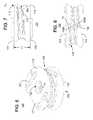
- FIGS. 11-13illustrate perspective, side, and anterior views, respectively, of an intervertebral stabilizer in accordance with one or more further embodiments of the present invention
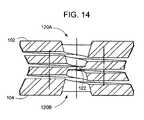
- FIG. 14is a sectional view of an intervertebral stabilizer in accordance with one or more further embodiments of the present invention.
- FIGS. 15-17illustrate perspective, anterior, and side views, respectively, of an intervertebral stabilizer element in accordance with one or more further embodiments of the present invention
- FIGS. 18-20illustrate perspective, side, and cross-sectional views, respectively, of an intervertebral stabilizer in accordance with one or more further embodiments of the present invention
- FIGS. 21-22illustrate perspective and side views, respectively, of an intervertebral stabilizer in accordance with one or more further embodiments of the present invention
- FIGS. 23-24illustrate perspective and side views, respectively, of an intervertebral stabilizer in accordance with one or more further embodiments of the present invention.
- FIGS. 25-26illustrate perspective and side views, respectively, of an intervertebral stabilizer in accordance with one or more further embodiments of the present invention.
- FIG. 27is a perspective view of an intervertebral trial in accordance with one or more embodiments of the present invention.
- FIG. 28is a perspective view of an alternative configuration of a spacer for the intervertebral trial of FIG. 27 ;
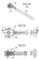
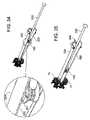
- FIGS. 29-31illustrate perspective, top, and lateral cross-sectional views, respectively, of an insertion tool suitable for implanting one or more of the intervertebral stabilizers herein;
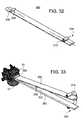
- FIG. 32is a perspective view of a wedge ramp insertion tool suitable for assisting in the implantation of one or more of the intervertebral stabilizers discussed herein;
- FIGS. 33-37are perspective views illustrating an implantation process utilizing the wedge ramps and insertion tools of FIGS. 29-32 ;
- FIGS. 38-39illustrate perspective and side views of an extraction tool suitable for repositioning and/or extracting one or more of the intervertebral stabilizers discussed herein.
- FIGS. 1-2illustrate an embodiment of a spinal intervertebral stabilizer 50 in accordance with one or more aspects of the present invention.
- the stabilizer 50is sized and shaped to fit in the intervertebral space between adjacent vertebral bones of the spine. It is understood that the size and shape of the stabilizer 50 may be adapted to fit in an intervertebral space at any level of the spine, such as the cervical spine, thoracic spine, or lumbar spine.
- the stabilizer 50is sized and shaped to be inserted into the inter-vertebral space from an anterior direction.
- the stabilizer 50includes an upper surface 52 of a first member 53 and a lower surface 54 of a second member 55 that are operable to engage end plates of the respective vertebral bones.
- a spring element in the form of a helical coil 56is interposed between the upper and lower surfaces 52 , 54 of the first and second members 53 , 55 .
- the helical coil 56includes at least one first segment 56 A having a first diameter and at least one second segment 56 B having a second diameter.
- two second segments 56 Bare disposed axially with respect to a single first segment 56 A, which is interposed between the second segments 56 B.
- the stabilizer 50may provide some movement in compressive and/or expansion directions due to the spaces between the respective turns of the second segments 56 B of the helical coil 56 . These spaces between the turns may be adjusted to provide differing amounts of compressive or expansion movement of the stabilizer 50 .
- the compressive and expansion movementmay also be adjusted by varying material properties of the segments 56 B.
- the stabilizer 50may also provide some movement in bending due to the first segment 56 A of the helical coil 56 . More particularly, the first and second segments 56 A, 56 B of the stabilizer 50 permits movement as to displacement, rotation, subluxation, flexion, extension, bending, or any combination thereof.
- FIGS. 3-4are conceptual illustrations of the spring properties of the first and second segments 56 A, 56 B, respectively, of the helical coil 56 as if employed separately.
- the relatively small spring diameter of the first segment 56 Apromotes bending (deflection f) because the deflection f is inversely proportional to an outside diameter D of the turns of the first segment 56 A.
- the resultant functionality of the helical coil 56is that one or more of the segments of the coil 56 permit compression/expansion and inhibit flexion (such as segments 56 B), while one or more other of the segments permit flexion and inhibit compression/expansion (such as segment 56 A).
- the first and second segments 56 A, 56 B of the stabilizer 50permit movement as to displacement, rotation, subluxation, flexion, extension, bending, or any combination thereof.
- the functionality of the varying diameter coil segments 56 A, 56 Bmay be adapted in an embodiment with a spring element having a more gradually changing diameter as is illustrated in FIG. 5 .
- This embodimentincludes a spinal intervertebral stabilizer 80 in accordance with one or more aspects of the present invention.
- the stabilizer 80is sized and shaped to fit in the intervertebral space between adjacent vertebral bones of the spine, and as with one or more other embodiments herein, it is understood that the size and shape of the stabilizer 80 may be adapted to fit in an intervertebral space at any level of the spine, such as the cervical spine, thoracic spine, or lumbar spine.
- the stabilizer 80includes a spring element having a plurality of segments, some of which promote compression/expansion, while others promote flexion.
- the spring elementis in the form of a helical coil of hourglass cross section.
- FIGS. 6-8illustrate an embodiment of a spinal intervertebral stabilizer 100 .
- the stabilizer 100is sized and shaped to fit in the intervertebral space between adjacent vertebral bones 10 , 12 of the spine. It is understood that the size and shape of the stabilizer 100 may be adapted to fit in an intervertebral space at any level of the spine, such as the cervical spine, thoracic spine, or lumbar spine.
- the stabilizer 100is sized and shaped to be inserted into the inter-vertebral space from an anterior direction.
- the stabilizer 100includes an upper surface 102 and a lower surface 104 that are operable to engage the end plates 14 , 16 of the respective vertebral bones 10 , 12 .
- the body 106 of the stabilizer 100is of generally cylindrical construction. As best seen in FIGS. 7-8 , a cross-sectional profile of the body 106 is hourglass shaped.
- the body 106also includes a spring element in the form of a helical coil in which a continuous or substantially continuous slot 108 extends helically from a terminal end 108 A adjacent the first surface 102 to a terminal end 108 B adjacent the second surface 104 .
- the slot 108provides the stabilizer 100 with a spring capability by creating respective turns or coils of the helical coil.
- the spring feature of the body 106may be formed from a helical wound spring, such as of circular, rectangular, or other shape cross-sectional configuration.
- the body 106is formed of a substantially solid cylindrical hollow body in which the helical coils are formed from the substantially continuous slot 108 that is cut into the body 106 through to the hollow portion 120 thereof.
- the upper surface 102 , the lower surface 104 , and the body 106are formed as an integral element, e.g., of single-piece construction.
- the stabilizer 100preferably takes the orientation shown.
- the spring features of the body 106are preferably designed such that the stabilizer 100 maintains a minimum distance between the vertebral bones 10 , 12 inasmuch as the surfaces 102 , 104 may not be compressed towards one another beyond a minimum distance.
- the stabilizer 100provides some movement in the compressive direction because the slot 108 provides some distance between the “coils” of the spring feature. This distance or space between the coils may be adjusted to provide differing amounts of compressive movement of the stabilizer 100 .
- the spacemay be at a minimum, such as zero, which would inhibit any compressive movement of the stabilizer 100 and also the vertebral bodies.
- the stabilizer 100limits the distance between the vertebral bodies, it permits some movement as to displacement, rotation, subluxation, flexion, extension, bending, or any combination thereof.
- the designpermits longitudinal or flexing by collapsing one side of the stabilizer 100 and expanding the other side.
- the center of rotation associated with flexingmay be well outside the inter-vertebral space, potentially one to five inches or more outside the inter-vertebral space.
- the upper surface 102includes a peripheral edge 112 that overhangs at least one coil of the body 106 , and preferably overhangs all of the coils of the body 106 .
- the lower surface 104includes a peripheral edge 114 that overhangs at least one coil of the body 106 , and preferably all of the coils of the body 106 .
- a moment arm Mais defined by a lateral distance between an outer surface of the at least one coil 110 of the body 106 and the peripheral edge 112 of the upper surface 102 .
- the same or another moment armmay also be defined in terms of the peripheral edge 114 of the lower surface 104 and the outer surface of the coil 110 .
- the moment arm Mamay also be defined in terms of the point at which the slot 108 collapses and respective adjacent coils engage one another. Irrespective of how the moment arm is defined, a compressive force Fc acting on, for example, at least a portion of the peripheral edge 112 and any portion of the lower surface 104 tends to collapse the spring of the body 106 and full compression of the spring results in closure of the slot 108 in the vicinity of the force Fc such that adjacent coils engage one another. Further compressive force Fc will work in conjunction with the moment arm Ma such that portions of the coils on an opposite side of the spring of the body 106 from the engaged coils tends to expand.
- a surgeonis preferably provided with a plurality of different sized intervertebral stabilizers 100 that he or she may utilize to fit the particular physiology of the patient.
- relatively larger intervertebral stabilizers 100will be useful in the lumbar region of the spine
- smaller sized intervertebral stabilizers 100will be useful in the thoracic region of the spine
- still smaller sized intervertebral stabilizers 100will be useful in the cervical spine.
- a height H of the intervertebral stabilizer 100e.g., measured between the upper and lower surface 102 , 104 ) is between about 8.0 mm to about 18.0 mm for use in the lumbar region of the spine.
- intervertebral stabilizers 100are preferably available to the surgeon, such as having a height of between (i) about 8.0 mm to 10.0 mm; (ii) about 10.0 mm to about 14.0 mm; and (iii) about 14.0 mm to about 18.0 mm.
- the spring feature of the body 106is preferably formed utilizing about 1.0 slot or 2.0 coils when the height of the intervertebral stabilizer 100 is about 8.0 mm to about 10.0 mm. In this context, about two turns or coils are created by one slot traversing at least partially around the body 106 .
- the spring feature of the body 106is preferably formed from about 2.0 slots or 3.0 coils when the height of the intervertebral stabilizer 100 is about 10.0 mm to about 14.0 mm. Additionally, the spring feature of the body 106 is preferably formed from about 3.0 slots or 4.0 coils when the height of the intervertebral stabilizer 100 is about 14.0 mm to about 18.0 mm.
- an intervertebral stabilizer 100 Ais preferably used in the cervical spine.
- the height of the intervertebral stabilizer 100 Ais preferably between about 6.0 mm to about 9.0 mm.
- the surgeonis preferably provided with a plurality of different sized intervertebral stabilizers 100 A for the cervical region of the spine.
- an intervertebral stabilizer 100 A having a height of about 5.0 mm to about 7.0 mmis formed in which the spring feature of the body 106 is formed utilizing about 3.0 slots or 4.0 coils.
- the heightis about 7.0 mm to about 9.0 mm and the spring feature of the body 106 is formed from about 4.0 slots or 5.0 coils.
- the intervertebral stabilizers 100 , 100 Amay include one or more bone adhesion facilitating elements 121 operable to promote bone adhesion to at least one of the upper and lower surface 102 , 104 .
- the bone adhesion facilitating elements 121may include one or more spikes oriented in any number of directions and being of generally triangular cross-section.
- Other embodiments of the inventioncontemplate that the bone adhesion facilitating elements are formed from one or more keels extending from the upper and/or lower surface 102 , 104 ; and/or from one or more roughening elements (such as dimpling or knurling) on one or both of the upper and lower surfaces 102 , 104 .
- the hollow portion 120 of the body 106may extend from the upper surface 102 to the lower surface 104 unimpeded.
- the hollow portion 120may include a membrane 122 disposed in the passage and substantially closing off the passage to inhibit bone growth therethrough.
- the membrane 122is formed as an integral element of the body 106 .
- the hollow portion 120may be formed from first and second hollow portions 120 A, 120 B that do not pass all the way through the body 106 .
- the hollow portion 120is preferably of hourglass shape.
- the shape of the hollow portion 120is preferably also hourglass shaped.
- the present inventionis not limited to any particular theory of operation, it is believed that such an hourglass shaped hole or hollow portion 120 maximizes or at least significantly increases the moment arm Ma, the offset between the compressive load application point at the peripheral edge (e.g. at 112 A in FIG. 1 ) and the outer surface of the spring element (e.g., at 110 ).
- FIGS. 15-17illustrate perspective, anterior, and side views, respectively, of an alternative embodiment of a spinal inter-vertebral stabilizer element 100 B.
- the stabilizer element 100 Bmay include some or all of the features discussed hereinabove with respect to the stabilizers 100 and/or 100 A. Respective peripheral edges 142 and 144 of the upper and lower surfaces 132 , 134 circumscribe a kidney shape.
- two of the stabilizer elements 100 Bare inserted into a single intervertebral space such that an overall envelope created by at least portions of the peripheral edges 142 and/or 144 of the two stabilizer element 100 B approximate the shape of the intervertebral space.
- the intervertebral stabilizer 100 Bis preferably sized and shaped to be inserted posteriorly or transversely into the intervertebral space.
- the stabilizer element 100 Bpreferably includes a length L measured along an anterior-to-posterior direction of the spine and a width W along a lateral direction of the spine.
- the width of the stabilizer element 100 Bis preferably smaller than the length thereof such that the stabilizer 100 B may be implanted from the posterior or transverse-posterior direction into the intervertebral space.
- the intervertebral stabilizer element 100 Bis preferably provided to the surgeon in a number of different sizes (for each mirror image thereof) to accommodate different levels in the spine and/or different physiology of a given patient. It is preferred that the height H of the stabilizer element 100 B (e.g., measured between the upper and lower surface 132 , 134 ) adheres to the various dimensions discussed hereinabove with respect to the stabilizer 100 .
- the height of the stabilizer element 100 Bis preferably characterized as being one of: (i) about 7.0 mm to about 15.0 mm when the spring element of the body 136 includes about 1.0 slot or 2.0 coils; (ii) about 11.0 mm to about 20.0 mm when the spring element of the body 136 includes about 2.0 slots or 3.0 coils; and (iii) about 13.0 mm to about 26.0 mm when the spring element of the body 136 includes about 3.0 slots or 4.0 coils.
- FIGS. 18-20are perspective, side and cross-sectional views, respectively, of a further embodiment 100 C of the present invention.
- the stabilizer 100 Cis substantially the same as the stabilizer 100 of FIGS. 6-8 .
- the stabilizer 100 Cincludes an upper surface 102 and a lower surface 104 that are operable to engage the end plates 14 , 16 of the respective vertebral bones 10 , 12 .
- the body 106 of the stabilizer 100 Cis of generally cylindrical construction and includes a spring element in the form of a helical coil in which a continuous or substantially continuous slot 108 extends helically from a terminal end adjacent the first surface 102 to a terminal end adjacent the second surface 104 .
- the cross-sectional profile of the body 106is only partially hourglass shaped. Indeed, the body 106 includes a substantially flat portion 106 ′ that does not have an hourglass contour.
- a hollow portion or aperture 120preferably extends from the surface 102 to the surface 104 .
- the hollow portion 102may also include the membrane 122 ( FIG. 14 ), and/or may also be hourglass shaped.
- the stabilizer 100 Dincludes an upper surface 102 and a lower surface 104 that are operable to engage the end plates of respective vertebral bones.
- the body 106 of the stabilizer 100 Dincludes a plurality of hourglass shaped segments 106 A, 106 B, etc. (two such segments being shown for illustration).
- the cross-sectional profile of the body 106is hourglass shaped; however, this embodiment of the invention include multiple hourglass shapes in axial alignment.
- a hollow portion or aperture 120preferably extends from the surface 102 to the surface 104 .
- the hollow portion 102may also include the membrane 122 ( FIG.
- the intervertebral stabilizer 100 Dmay include one or more bone adhesion facilitating elements 121 operable to promote bone adhesion to at least one of the upper and lower surface 102 , 104 .
- the bone adhesion facilitating elements 121may include one or more spikes oriented in any number of directions and being of generally triangular cross-section.
- Other embodiments of the inventioncontemplate that the bone adhesion facilitating elements are formed from one or more keels extending from the upper and/or lower surface 102 , 104 ; and/or from one or more roughening elements (such as dimpling or knurling) on one or both of the upper and lower surfaces 102 , 104 .
- the stabilizer 100 Dmay include a flange 160 of generally transverse orientation with respect to the end surface (e.g., surface 102 ) and operable to engage a sidewall of the vertebral bone by driving one or more screws through aperture(s) 162 of the flange 160 into the vertebral bone.
- the stabilizer 100 Dincludes one or more bone adhesion facilitating elements 121 (e.g., spikes) on the surface 104 and a flange 160 extending from the surface 102 .
- Other combinationsmay be employed without departing from the spirit and scope of the invention.
- FIGS. 23-24are perspective and side views, respectively, of a further embodiment of the present invention. While the embodiments of the invention discussed above may be used to stabilize a single pair of vertebral bones, the stabilizer 100 E is operable to accommodate a larger space for multiple levels of intervertebral bones.
- the stabilizer 100 Eincludes an upper surface 102 and a lower surface 104 that are operable to engage the end plates of respective vertebral bones.
- the vertebral bonesneed not be adjacent to one another; rather, a vertebral bone of an intervening level may be removed and the remaining vertebral bones may be stabilized using the stabilizer 100 E.
- the body 106 of the stabilizer 100 Eincludes a plurality of axially aligned, hourglass shaped segments 106 A, 106 B (two such segments being shown for illustration). A further segment 106 C is interposed between the hourglass segments 106 A, 106 B, where the segment 106 C does not include a spring feature. The segment 106 C accounts for the removed vertebral bone. As shown, the stabilizer 100 E includes one or more bone adhesion facilitating elements 121 (e.g., spikes) on the surface 104 and a flange 160 extending from the surface 102 . Other combinations may be employed without departing from the spirit and scope of the invention.
- bone adhesion facilitating elements 121e.g., spikes
- FIGS. 25-26are perspective and side views, respectively, of a further embodiment 100 F of the present invention.
- the stabilizer 100 Fis operable to accommodate multi-level stabilization.
- the stabilizer 100 Fincludes an upper surface 102 and a lower surface 104 that are operable to engage the end plates of respective vertebral bones.
- the vertebral bonesare not adjacent to one another; rather, two or more vertebral bones of intervening level(s) may be removed and the remaining vertebral bones may be stabilized using the stabilizer 100 F.
- the body 106 of the stabilizer 100 Fincludes a plurality of axially aligned, hourglass shaped segments 106 A, 106 B, 106 E (three such segments being shown for illustration). Further segments 106 C and 106 D are interposed between the hourglass segments 106 A, 106 B and between 106 B, 106 E, respectively. The segments 106 C and 106 D do not include spring features as they account for the removed vertebral bones. As shown, the stabilizer 100 E includes a flange 160 on the surfaces 102 , 104 to secure the stabilizer 100 F. It is noted that further bone adhesion promoting elements may also be employed without departing from the spirit and scope of the invention.
- FIG. 27is a perspective view of an intervertebral trial 200 which is preferably used to prepare the end plates 14 , 16 of the intervertebral bones 10 , 12 , respectively, prior to implantation of the stabilizer 100 . More particularly, after anterior incision and access to the intervertebral bones 10 , 12 is obtained, the intervertebral space between the end plates 14 , 16 is evacuated by removing the disk, some connecting tissue, etc. Next, the trial 200 is utilized to abrade the end plates 14 , 16 of the vertebral bones 10 , 12 .
- the trial 200includes a handle 202 and at least one spacer element 204 .
- another spacer 206(preferably of different size or character) is included at an opposite end of the handle from the spacer 204 .
- spacer element 204For purposes of brevity, reference will now be made only to spacer element 204 , it being understood that the description of spacer 204 may be applied to spacer 206 with equal force.
- the spacer element 204depends from the handle 202 and is preferably sized and shaped to fit in the intervertebral space between the respective end plates 14 , 16 .
- the spacer element 204includes an upper surface 208 and a lower surface 210 that are spaced apart by a height dimension.
- the heightis of a sufficient magnitude to at least slightly expand the intervertebral space when the spacer element 204 is urged between the end plates 14 , 16 .
- the upper surface 208preferably engages the end plate 14
- the lower surface 210engages the end plate 16 .
- At least one of the upper and lower surfaces 208 , 210preferably includes a roughening element 212 , such that insertion of the spacer element 204 into the intervertebral space abrades the associated end plate in preparation for implantation of the intervertebral stabilizer 100 .
- both the upper and lower surface 208 , 210include a roughening element 212 such that insertion of the spacer element 204 into the intervertebral space simultaneously abrades both end plates 14 , 16 .
- the roughening elementis formed from substantially sharp knurling disposed on the respective surfaces 208 , 210 .
- the shape of the spacer element 204may be kidney shaped for posterior or lateral implantation.
- the surgeonis provided with a plurality of trials 200 , each with differing sized spacer elements 204 , 206 , such that the surgeon may choose an appropriate sized trial 200 in order to prepare the intervertebral space for implantation.
- the plurality of trials 200may include differing levels of roughness, for example, by adjusting the sharpness and magnitude of the knurling 212 .
- the abrasion of the end plates 14 , 16facilitates bone growth and secure engagement of the upper and lower surfaces 102 , 104 of the stabilizer 100 upon implantation into the intervertebral space.
- an insertion tool 250is preferably utilized to implant an intervertebral stabilizer, such as one or more of the intervertebral stabilizers discussed above into the intervertebral space.
- an intervertebral stabilizersuch as one or more of the intervertebral stabilizers discussed above into the intervertebral space.
- reference to the stabilizer 100 of FIGS. 6-8will be made, it being understood that the description may be applied to the other stabilizer embodiments contemplated herein.
- the insertion tool 250includes a handle 252 and a head 254 .
- the head 254is operable to releasably engage the intervertebral stabilizer 100 such that the surgeon may manipulate the position of the stabilizer 100 by way of the handle 252 in order to urge the stabilizer 100 into the intervertebral space.
- the head 254includes at least a pair of spaced apart pins 256 , 258 that facilitate the engagement between the head 254 and the intervertebral stabilizer 100 .
- the intervertebral stabilizer 100may include at least a pair of spaced apart apertures 150 , 152 operable to receive the pins 256 , 258 of the insertion tool 250 .
- a longitudinal axis A of the stabilizer 100is normal to the first and second surface 102 , 104 and the apertures 150 , 152 extend transversely with respect to the longitudinal axis A.
- the apertures 150 , 152may extend at least partially into the body 106 , although it is preferred that the apertures 150 , 152 extend all the way through the body 106 into the hollow portion 120 .
- the apertures 150 , 152are preferably disposed on an anteriorly directed side of the body 106 .
- the insertion tool 250engages the intervertebral stabilizer 100 from the anterior direction such that the surgeon may urge the stabilizer 100 into the intervertebral space from the anterior direction.
- the apertures 150 , 152are preferably positioned longitudinal with respect to one another, parallel to the longitudinal axis A.
- the aperture 150is disposed toward the first surface 102 and the second aperture 152 is disposed toward the second surface 104 .
- the apertures 150 , 152are entirely within the body 106 such that they form a closed interior surface.
- the apertures 150 , 152are disposed at terminal ends 108 A, 108 B of the slit 108 such that the slit 108 communicates with the interior of the respective apertures 150 , 152 .
- an alternative embodimentmay provide a pair of apertures 154 , 156 that extend only partially into the body 106 such that respective slots are formed at the first and second surfaces 102 , 104 .
- one or more spikes, keels, or roughening elements 121are disposed at least partially along the slot.
- a dual functionmay be enjoyed, namely: (i) the spikes assist in forming the slot, thereby facilitating engagement between the insertion tool 250 and stabilizer 100 A; and (ii) once implanted, the stabilizer 100 A is encouraged to remain in the implanted position owing to the spikes 121 engaging the respective end plates 14 , 16 .
- one or more apertures 158may be provided in the body 136 of the stabilizer element 100 B in order to assist in the implantation of the element 100 B into the intervertebral space from a posterior or transverse posterior direction.
- the aperture 158is posteriorly directed.
- the pins 256 , 258are preferably flexible in a direction parallel to the longitudinal axis A ( FIG. 6 ) of the stabilizer 100 .
- the apertures 150 , 152urge the pins 254 , 258 apart when the head 254 engages the stabilizer 100 .
- the pins 254 , 258may urge the upper and lower surface 102 , 104 together when the head 254 engages the stabilizer 100 .
- a height of the head 254(measured parallel to the longitudinal axis A) is preferably less than the height of the stabilizer 100 . This insures that the head 254 does not interfere with the implantation of the stabilizer 100 in the intervertebral space.
- the head 254is preferably sized such that it at least partially enters into the depression defined by the hourglass shape of the body 106 . It is preferred that the contour of the head 254 matches the curvature of the body 106 as is best seen in FIG. 31 .
- the head 254preferably flairs out in a transverse (e.g., perpendicular) direction to the longitudinal axis A and terminates at respective prongs 260 , 262 that provide lateral engagement with the body 106 of the stabilizer 100 . This advantageously assists in the lateral stability of the engaged insertion tool and stabilizer 100 as the stabilizer 100 is implanted into the intervertebral space.
- FIGS. 32 and 33illustrate a further insertion tool for implantation of the intervertebral stabilizer 100 from an anterior direction.
- the insertion toolpreferably includes first and second elongate ramps 300 , 302 that cooperate to assist in the implantation of the stabilizer 100 into the intervertebral space.
- a single ramp 300is shown in FIG. 32 , it being understood that the ramp 302 is substantially similar as will be evident to one of ordinary skill in the art after reviewing this specification.
- Each elongate ramp 300 , 302includes a proximal end 304 and a distal end 306 .
- the distal end 306is sized and shaped for insertion into the intervertebral space in order to engage one of the end plates.
- the end 306preferably includes a stop member 308 that is operable to engage the associated intervertebral bone and to limit a distance that the distal end 306 may enter into the intervertebral space. As best seen in FIG. 33 , the stop 308 abuts the vertebral bone 10 .
- first and second ramps 300 , 302are disposed opposite to one another to define upper and lower surfaces 320 , 322 when the distal ends 306 thereof are inserted into the intervertebral space.
- the proximal ends 304 of the ramps 300 , 302are preferably fixed positionally with respect to one another by a clamp member 310 . More particularly, each of the distal ends 304 includes a bore 312 into which an end of the clamp 310 may be inserted.
- the clamp 310is preferably of a U-shape in order to fix the relative positions of the proximal ends 304 with respect to one another. It is noted that the surgeon may omit use of the clamp if he or she insures that the proximal ends 304 of the ramps 300 , 302 are fixed with respect to one another by clamping same with his or her hand.
- the intervertebral stabilizer 100is preferably slid along the surfaces 320 , 322 from the proximal end 304 toward the distal end 306 .
- respective protrusionssuch as spikes 121 are spaced apart on at least one of the upper and lower surface 102 , 104 of the stabilizer 100 at a distance to accommodate a width of the ramps 300 , 302 .
- slideable engagement of the spikes 121 with respective lateral edges 324 , 326 of the ramps 300 , 302insure that the stabilizer 100 slides properly along the surfaces 320 , 322 and remains between the ramps 300 , 302 .
- the lateral edges 324 , 326are chamfered in an appropriate way to complement the contour of the spikes 121 to improve slideability and/or stability of the intervertebral stabilizer 100 as it slides along the ramps 300 , 302 .
- the substantially fixed positions of the distal ends 304 of the ramps 300 , 302 and the sliding intervertebral stabilizer 100at least opens the intervertebral space owing to the lever action of the ramps 300 , 302 . It is also preferred that simultaneously with the opening of the intervertebral space, the intervertebral stabilizer 100 is compressed.
- an extractor 350may be utilized.
- the extractor 350preferably includes a handle 352 having proximal and distal ends 354 , 356 , respectively.
- the extraction tool 350preferably further includes an engagement element 358 depending from the proximal end 356 .
- the engagement element 358is preferably operable to releaseably engage the stabilizer 100 after it has been positioned within the intervertebral space. More particularly, the engagement element includes a longitudinally extending member 360 and a transversely extending member 362 .
- the longitudinally extending member 360is preferably sized such that is may pass through one or more of the apertures 150 , 152 (or any of the other aperture embodiments herein).
- the transversely extending member 362is preferably sized to pass through the slit 108 as the longitudinally extending member 360 is inserted into the aperture, for example, aperture 150 .
- the longitudinally extending member 360is preferably of sufficient length to cause the transversely extending member 362 to enter the hollow portion 120 of the body 106 . Thereafter, the surgeon preferably rotates the handle 352 of the extraction tool 350 such that the transversely extending member 362 engages an interior surface of the hollow portion 120 such that the stabilizer 100 may be pulled by the handle 352 of the extraction tool 350 .
- the engagement element 358includes a threaded portion (not shown) that may be screwed into a threaded aperture in order to engage the stabilizer.
- the aperture 158 ( FIG. 15 ) of the stabilizer element 100 Bmay be threaded and the engagement element 358 of the extraction tool 350 may be threaded into the aperture 158 to permit the surgeon to reposition and/or extract the stabilizer element 100 B.
Landscapes
- Health & Medical Sciences (AREA)
- Engineering & Computer Science (AREA)
- Orthopedic Medicine & Surgery (AREA)
- Biomedical Technology (AREA)
- Transplantation (AREA)
- Heart & Thoracic Surgery (AREA)
- Oral & Maxillofacial Surgery (AREA)
- Cardiology (AREA)
- Vascular Medicine (AREA)
- Life Sciences & Earth Sciences (AREA)
- Animal Behavior & Ethology (AREA)
- General Health & Medical Sciences (AREA)
- Public Health (AREA)
- Veterinary Medicine (AREA)
- Neurology (AREA)
- Physical Education & Sports Medicine (AREA)
- Prostheses (AREA)
Abstract
Description
Claims (17)
Priority Applications (3)
| Application Number | Priority Date | Filing Date | Title |
|---|---|---|---|
| US11/176,915US7578848B2 (en) | 2005-03-03 | 2005-07-07 | Intervertebral stabilizer |
| PCT/US2005/027506WO2006096204A1 (en) | 2005-03-03 | 2005-08-03 | Intervertebral stabilizer, method of use, and instrumentation therefor |
| EP05778926AEP1853201A1 (en) | 2005-03-03 | 2005-08-03 | Intervertebral stabilizer, method of use, and instrumentation therefor |
Applications Claiming Priority (2)
| Application Number | Priority Date | Filing Date | Title |
|---|---|---|---|
| US65834505P | 2005-03-03 | 2005-03-03 | |
| US11/176,915US7578848B2 (en) | 2005-03-03 | 2005-07-07 | Intervertebral stabilizer |
Publications (2)
| Publication Number | Publication Date |
|---|---|
| US20060200242A1 US20060200242A1 (en) | 2006-09-07 |
| US7578848B2true US7578848B2 (en) | 2009-08-25 |
Family
ID=36953683
Family Applications (5)
| Application Number | Title | Priority Date | Filing Date |
|---|---|---|---|
| US11/176,915Expired - Fee RelatedUS7578848B2 (en) | 2005-03-03 | 2005-07-07 | Intervertebral stabilizer |
| US11/176,916Expired - Fee RelatedUS7585324B2 (en) | 2005-03-03 | 2005-07-07 | Cervical intervertebral stabilizer |
| US11/176,717Expired - Fee RelatedUS7575598B2 (en) | 2005-03-03 | 2005-07-07 | Anterior lumbar intervertebral stabilizer |
| US11/176,175Expired - Fee RelatedUS7578847B2 (en) | 2005-03-03 | 2005-07-07 | Posterior lumbar intervertebral stabilizer |
| US11/176,914Expired - Fee RelatedUS7582114B2 (en) | 2005-03-03 | 2005-07-07 | Intervertebral stabilizer, methods of use, and instrumentation therefor |
Family Applications After (4)
| Application Number | Title | Priority Date | Filing Date |
|---|---|---|---|
| US11/176,916Expired - Fee RelatedUS7585324B2 (en) | 2005-03-03 | 2005-07-07 | Cervical intervertebral stabilizer |
| US11/176,717Expired - Fee RelatedUS7575598B2 (en) | 2005-03-03 | 2005-07-07 | Anterior lumbar intervertebral stabilizer |
| US11/176,175Expired - Fee RelatedUS7578847B2 (en) | 2005-03-03 | 2005-07-07 | Posterior lumbar intervertebral stabilizer |
| US11/176,914Expired - Fee RelatedUS7582114B2 (en) | 2005-03-03 | 2005-07-07 | Intervertebral stabilizer, methods of use, and instrumentation therefor |
Country Status (3)
| Country | Link |
|---|---|
| US (5) | US7578848B2 (en) |
| EP (1) | EP1853201A1 (en) |
| WO (1) | WO2006096204A1 (en) |
Cited By (12)
| Publication number | Priority date | Publication date | Assignee | Title |
|---|---|---|---|---|
| US20090105835A1 (en)* | 2007-10-22 | 2009-04-23 | Spinalmotion, Inc. | Vertebral Body Replacement and Method for Spanning a Space Formed upon Removal of a Vertebral Body |
| US8029574B2 (en) | 2006-11-07 | 2011-10-04 | Biomedflex Llc | Prosthetic knee joint |
| US8070823B2 (en) | 2006-11-07 | 2011-12-06 | Biomedflex Llc | Prosthetic ball-and-socket joint |
| US8308812B2 (en) | 2006-11-07 | 2012-11-13 | Biomedflex, Llc | Prosthetic joint assembly and joint member therefor |
| US8512413B2 (en) | 2006-11-07 | 2013-08-20 | Biomedflex, Llc | Prosthetic knee joint |
| US9005307B2 (en) | 2006-11-07 | 2015-04-14 | Biomedflex, Llc | Prosthetic ball-and-socket joint |
| US9005306B2 (en) | 2006-11-07 | 2015-04-14 | Biomedflex, Llc | Medical Implants With Compliant Wear-Resistant Surfaces |
| US9358122B2 (en) | 2011-01-07 | 2016-06-07 | K2M, Inc. | Interbody spacer |
| US9566157B2 (en) | 2006-11-07 | 2017-02-14 | Biomedflex, Llc | Three-member prosthetic joint |
| US9700425B1 (en) | 2011-03-20 | 2017-07-11 | Nuvasive, Inc. | Vertebral body replacement and insertion methods |
| US11701241B2 (en) | 2021-06-28 | 2023-07-18 | Spine Wave, Inc. | Bellows shaped spinal implant |
| US11826265B2 (en) | 2021-06-28 | 2023-11-28 | Spine Wave, Inc. | Bellows shaped spinal implant having gyroid lattice structures |
Families Citing this family (128)
| Publication number | Priority date | Publication date | Assignee | Title |
|---|---|---|---|---|
| US7918888B2 (en)* | 1999-10-13 | 2011-04-05 | Hamada James S | Spinal fusion instrumentation, implant and method |
| FR2824261B1 (en) | 2001-05-04 | 2004-05-28 | Ldr Medical | INTERVERTEBRAL DISC PROSTHESIS AND IMPLEMENTATION METHOD AND TOOLS |
| US7041309B2 (en) | 2002-06-13 | 2006-05-09 | Neuropro Technologies, Inc. | Spinal fusion using an HMG-CoA reductase inhibitor |
| FR2846550B1 (en) | 2002-11-05 | 2006-01-13 | Ldr Medical | INTERVERTEBRAL DISC PROSTHESIS |
| ZA200506029B (en) | 2003-01-31 | 2006-10-25 | Spinalmotion Inc | Spinal Midline Indicator |
| WO2004066884A1 (en) | 2003-01-31 | 2004-08-12 | Spinalmotion, Inc. | Intervertebral prosthesis placement instrument |
| AU2004212942A1 (en) | 2003-02-14 | 2004-09-02 | Depuy Spine, Inc. | In-situ formed intervertebral fusion device |
| US20090076614A1 (en)* | 2007-09-17 | 2009-03-19 | Spinalmotion, Inc. | Intervertebral Prosthetic Disc with Shock Absorption Core |
| US7442211B2 (en) | 2003-05-27 | 2008-10-28 | Spinalmotion, Inc. | Intervertebral prosthetic disc |
| US7575599B2 (en) | 2004-07-30 | 2009-08-18 | Spinalmotion, Inc. | Intervertebral prosthetic disc with metallic core |
| US10052211B2 (en) | 2003-05-27 | 2018-08-21 | Simplify Medical Pty Ltd. | Prosthetic disc for intervertebral insertion |
| US7588590B2 (en) | 2003-12-10 | 2009-09-15 | Facet Solutions, Inc | Spinal facet implant with spherical implant apposition surface and bone bed and methods of use |
| FR2865629B1 (en) | 2004-02-04 | 2007-01-26 | Ldr Medical | INTERVERTEBRAL DISC PROSTHESIS |
| EP2113227B1 (en) | 2004-02-04 | 2015-07-29 | LDR Medical | Intervertebral disc prosthesis |
| US8562649B2 (en) | 2004-02-17 | 2013-10-22 | Gmedelaware 2 Llc | System and method for multiple level facet joint arthroplasty and fusion |
| US8333789B2 (en) | 2007-01-10 | 2012-12-18 | Gmedelaware 2 Llc | Facet joint replacement |
| FR2869528B1 (en) | 2004-04-28 | 2007-02-02 | Ldr Medical | INTERVERTEBRAL DISC PROSTHESIS |
| US7507242B2 (en) | 2004-06-02 | 2009-03-24 | Facet Solutions | Surgical measurement and resection framework |
| US7585326B2 (en) | 2004-08-06 | 2009-09-08 | Spinalmotion, Inc. | Methods and apparatus for intervertebral disc prosthesis insertion |
| US8597360B2 (en) | 2004-11-03 | 2013-12-03 | Neuropro Technologies, Inc. | Bone fusion device |
| FR2879436B1 (en) | 2004-12-22 | 2007-03-09 | Ldr Medical | INTERVERTEBRAL DISC PROSTHESIS |
| US8083797B2 (en) | 2005-02-04 | 2011-12-27 | Spinalmotion, Inc. | Intervertebral prosthetic disc with shock absorption |
| US20060293752A1 (en)* | 2005-06-27 | 2006-12-28 | Missoum Moumene | Intervertebral disc prosthesis and associated methods |
| FR2887762B1 (en) | 2005-06-29 | 2007-10-12 | Ldr Medical Soc Par Actions Si | INTERVERTEBRAL DISC PROSTHESIS INSERTION INSTRUMENTATION BETWEEN VERTEBRATES |
| WO2008103781A2 (en) | 2007-02-21 | 2008-08-28 | Benvenue Medical, Inc. | Devices for treating the spine |
| US8366773B2 (en) | 2005-08-16 | 2013-02-05 | Benvenue Medical, Inc. | Apparatus and method for treating bone |
| AU2006279558B2 (en) | 2005-08-16 | 2012-05-17 | Izi Medical Products, Llc | Spinal tissue distraction devices |
| FR2891135B1 (en) | 2005-09-23 | 2008-09-12 | Ldr Medical Sarl | INTERVERTEBRAL DISC PROSTHESIS |
| JP5167494B2 (en)* | 2005-10-10 | 2013-03-21 | ドナ・ジーン・カーヴァー | Artificial intervertebral disc replacement system and method |
| FR2893838B1 (en) | 2005-11-30 | 2008-08-08 | Ldr Medical Soc Par Actions Si | PROSTHESIS OF INTERVERTEBRAL DISC AND INSTRUMENTATION OF INSERTION OF THE PROSTHESIS BETWEEN VERTEBRATES |
| WO2007075411A2 (en)* | 2005-12-16 | 2007-07-05 | Thomas Haider Patents, A Limited Liability Company | An intervertebral prosthesis for supporting adjacent vertebral bodies enabling the creation of soft fusion and method |
| WO2007075878A2 (en)* | 2005-12-22 | 2007-07-05 | Endius, Inc. | Methods and devices for replacement of intervertebral discs |
| US7766918B2 (en)* | 2006-01-31 | 2010-08-03 | Warsaw Orthopedic, Inc. | Spinal disc replacement surgical instrument and methods for use in spinal disc replacement |
| WO2007121320A2 (en) | 2006-04-12 | 2007-10-25 | Spinalmotion, Inc. | Posterior spinal device and method |
| US7740659B2 (en)* | 2006-06-29 | 2010-06-22 | Depuy Spine, Inc. | Insert for nucleus implant |
| US8906096B2 (en) | 2006-08-15 | 2014-12-09 | GMFDelaware 2 LLC | Spinal implant |
| US9526525B2 (en) | 2006-08-22 | 2016-12-27 | Neuropro Technologies, Inc. | Percutaneous system for dynamic spinal stabilization |
| US20080161923A1 (en)* | 2006-09-28 | 2008-07-03 | Matthew Parsons | Intervertebral Motion Disc Having A Resorbable Keel |
| WO2008070863A2 (en) | 2006-12-07 | 2008-06-12 | Interventional Spine, Inc. | Intervertebral implant |
| USD585553S1 (en) | 2007-02-22 | 2009-01-27 | Zimmer Spine, Inc. | Spinal implant |
| US8465546B2 (en) | 2007-02-16 | 2013-06-18 | Ldr Medical | Intervertebral disc prosthesis insertion assemblies |
| EP2124778B1 (en) | 2007-02-21 | 2019-09-25 | Benvenue Medical, Inc. | Devices for treating the spine |
| BRPI0808018A2 (en)* | 2007-03-07 | 2014-06-17 | Ulrich Gmbh & Co Kg | INTERVERTEBRAL IMPLANT WITH AN ELASTIC COMPONENT |
| FR2916956B1 (en) | 2007-06-08 | 2012-12-14 | Ldr Medical | INTERSOMATIC CAGE, INTERVERTEBRAL PROSTHESIS, ANCHORING DEVICE AND IMPLANTATION INSTRUMENTATION |
| US8900307B2 (en) | 2007-06-26 | 2014-12-02 | DePuy Synthes Products, LLC | Highly lordosed fusion cage |
| US8298287B2 (en)* | 2007-06-26 | 2012-10-30 | Depuy Spine, Inc. | Intervertebral motion disc with helical shock absorber |
| US20090043391A1 (en) | 2007-08-09 | 2009-02-12 | Spinalmotion, Inc. | Customized Intervertebral Prosthetic Disc with Shock Absorption |
| US8801758B2 (en)* | 2007-08-13 | 2014-08-12 | Stryker Spine | Insertion instrument for intervertebral implants |
| US20090076608A1 (en)* | 2007-09-17 | 2009-03-19 | Vermillion Technologies, Llc | Intervertebral disc replacement prosthesis |
| FR2921820B1 (en)* | 2007-10-05 | 2011-09-16 | Vincent Pointillart | INTERVERTEBRAL PROSTHESIS |
| US8591587B2 (en) | 2007-10-30 | 2013-11-26 | Aesculap Implant Systems, Llc | Vertebral body replacement device and method for use to maintain a space between two vertebral bodies within a spine |
| US8142441B2 (en)* | 2008-10-16 | 2012-03-27 | Aesculap Implant Systems, Llc | Surgical instrument and method of use for inserting an implant between two bones |
| US20090157185A1 (en)* | 2007-12-18 | 2009-06-18 | Chong Chol Kim | Prosthetic Monolithic Spinal Discs and Method of Customizing and Constructing Discs |
| EP2237748B1 (en) | 2008-01-17 | 2012-09-05 | Synthes GmbH | An expandable intervertebral implant |
| EP2249747B1 (en)* | 2008-03-07 | 2013-12-25 | Synthes GmbH | Expandable interbody spacer device |
| US8764833B2 (en) | 2008-03-11 | 2014-07-01 | Spinalmotion, Inc. | Artificial intervertebral disc with lower height |
| US20110029087A1 (en)* | 2008-04-04 | 2011-02-03 | Haider Thomas T | Intervertebral prostheses with compliant filler material for supporting adjacent vertebral bodies and method |
| US8936641B2 (en) | 2008-04-05 | 2015-01-20 | DePuy Synthes Products, LLC | Expandable intervertebral implant |
| US9034038B2 (en) | 2008-04-11 | 2015-05-19 | Spinalmotion, Inc. | Motion limiting insert for an artificial intervertebral disc |
| EP2278941A1 (en) | 2008-05-05 | 2011-02-02 | Spinalmotion Inc. | Polyaryletherketone artificial intervertebral disc |
| US9220603B2 (en) | 2008-07-02 | 2015-12-29 | Simplify Medical, Inc. | Limited motion prosthetic intervertebral disc |
| EP2299944A4 (en) | 2008-07-17 | 2013-07-31 | Spinalmotion Inc | SYSTEM FOR INSTALLING ARTIFICIAL INTERVERTEBRAL DISCS |
| EP2299941A1 (en) | 2008-07-18 | 2011-03-30 | Spinalmotion Inc. | Posterior prosthetic intervertebral disc |
| US10045860B2 (en) | 2008-12-19 | 2018-08-14 | Amicus Design Group, Llc | Interbody vertebral prosthetic device with self-deploying screws |
| US8535327B2 (en) | 2009-03-17 | 2013-09-17 | Benvenue Medical, Inc. | Delivery apparatus for use with implantable medical devices |
| US9526620B2 (en) | 2009-03-30 | 2016-12-27 | DePuy Synthes Products, Inc. | Zero profile spinal fusion cage |
| US9393129B2 (en) | 2009-12-10 | 2016-07-19 | DePuy Synthes Products, Inc. | Bellows-like expandable interbody fusion cage |
| KR20120121396A (en)* | 2010-02-22 | 2012-11-05 | 신세스 게엠바하 | Total disc replacement with w-shaped spring elements |
| US8353957B2 (en) | 2010-04-20 | 2013-01-15 | Warsaw Orthopedic, Inc. | Expandable medical device and method |
| FR2960146B1 (en)* | 2010-05-18 | 2012-12-28 | Charles Khalife | DYNAMIC INTER VERTEBRAL DISC |
| US9907560B2 (en) | 2010-06-24 | 2018-03-06 | DePuy Synthes Products, Inc. | Flexible vertebral body shavers |
| US8979860B2 (en) | 2010-06-24 | 2015-03-17 | DePuy Synthes Products. LLC | Enhanced cage insertion device |
| US8623091B2 (en) | 2010-06-29 | 2014-01-07 | DePuy Synthes Products, LLC | Distractible intervertebral implant |
| US9066810B2 (en)* | 2010-09-20 | 2015-06-30 | DePuy Synthes Products, Inc. | Compliant implant |
| US9402732B2 (en) | 2010-10-11 | 2016-08-02 | DePuy Synthes Products, Inc. | Expandable interspinous process spacer implant |
| KR101052833B1 (en)* | 2010-10-28 | 2011-07-29 | 박경우 | Flexible intervertebral cage |
| US8814873B2 (en) | 2011-06-24 | 2014-08-26 | Benvenue Medical, Inc. | Devices and methods for treating bone tissue |
| WO2013023096A1 (en) | 2011-08-09 | 2013-02-14 | Neuropro Technologies, Inc. | Bone fusion device, system and method |
| US9358123B2 (en) | 2011-08-09 | 2016-06-07 | Neuropro Spinal Jaxx, Inc. | Bone fusion device, apparatus and method |
| US10420654B2 (en) | 2011-08-09 | 2019-09-24 | Neuropro Technologies, Inc. | Bone fusion device, system and method |
| ES2770824T3 (en) | 2012-03-19 | 2020-07-03 | Amicus Design Group Llc | Intervertebral fusion prosthetic and orthopedic device with self-deploying anchors |
| US9566165B2 (en) | 2012-03-19 | 2017-02-14 | Amicus Design Group, Llc | Interbody vertebral prosthetic and orthopedic fusion device with self-deploying anchors |
| US10159583B2 (en) | 2012-04-13 | 2018-12-25 | Neuropro Technologies, Inc. | Bone fusion device |
| US9532883B2 (en) | 2012-04-13 | 2017-01-03 | Neuropro Technologies, Inc. | Bone fusion device |
| ES2544274T3 (en)* | 2012-10-24 | 2015-08-28 | Waldemar Link Gmbh & Co. Kg | Support for a medical implant |
| US8945228B2 (en) | 2012-11-15 | 2015-02-03 | DePuy Synthes Products, LLC | Endplate for a vertebral implant |
| US9717601B2 (en) | 2013-02-28 | 2017-08-01 | DePuy Synthes Products, Inc. | Expandable intervertebral implant, system, kit and method |
| US9522070B2 (en) | 2013-03-07 | 2016-12-20 | Interventional Spine, Inc. | Intervertebral implant |
| US10085783B2 (en) | 2013-03-14 | 2018-10-02 | Izi Medical Products, Llc | Devices and methods for treating bone tissue |
| CA2906531C (en) | 2013-03-15 | 2020-10-06 | Neuropro Technologies, Inc. | Bodiless bone fusion device, apparatus and method |
| EP2777628B1 (en)* | 2013-03-15 | 2018-02-28 | Neos Surgery, S.L. | Device for repairing an intervertebral disc |
| US9675465B2 (en)* | 2014-05-15 | 2017-06-13 | Globus Medical, Inc. | Standalone interbody implants |
| US11426290B2 (en) | 2015-03-06 | 2022-08-30 | DePuy Synthes Products, Inc. | Expandable intervertebral implant, system, kit and method |
| US20160270928A1 (en)* | 2015-03-18 | 2016-09-22 | Baui Biotech Co., Ltd. | Spinal spacer |
| US10449051B2 (en)* | 2015-04-29 | 2019-10-22 | Institute for Musculoskeletal Science and Education, Ltd. | Implant with curved bone contacting elements |
| US10492921B2 (en) | 2015-04-29 | 2019-12-03 | Institute for Musculoskeletal Science and Education, Ltd. | Implant with arched bone contacting elements |
| JP6768001B2 (en) | 2015-04-29 | 2020-10-14 | インスティテュート フォー マスキュロスケレタル サイエンス アンド エジュケイション,リミテッド | Coiled implants and systems and how to make them |
| DE102015117129A1 (en)* | 2015-10-07 | 2017-04-13 | Aesculap Ag | Artificial joint implant |
| US11298931B2 (en) | 2015-11-24 | 2022-04-12 | Agada Medical Ltd. | Intervertebral disc replacement |
| US10390959B2 (en) | 2015-11-24 | 2019-08-27 | Agada Medical Ltd. | Intervertebral disc replacement |
| EP3386444B1 (en)* | 2015-12-07 | 2020-11-18 | Nexus Spine, L.L.C. | Porous interbody spacer |
| EP3474784A2 (en) | 2016-06-28 | 2019-05-01 | Eit Emerging Implant Technologies GmbH | Expandable and angularly adjustable intervertebral cages with articulating joint |
| US11510788B2 (en) | 2016-06-28 | 2022-11-29 | Eit Emerging Implant Technologies Gmbh | Expandable, angularly adjustable intervertebral cages |
| WO2018031801A1 (en)* | 2016-08-11 | 2018-02-15 | Amnon Yadin | Intervertebral disc replacement |
| US10478312B2 (en) | 2016-10-25 | 2019-11-19 | Institute for Musculoskeletal Science and Education, Ltd. | Implant with protected fusion zones |
| US11033394B2 (en) | 2016-10-25 | 2021-06-15 | Institute for Musculoskeletal Science and Education, Ltd. | Implant with multi-layer bone interfacing lattice |
| US10888433B2 (en) | 2016-12-14 | 2021-01-12 | DePuy Synthes Products, Inc. | Intervertebral implant inserter and related methods |
| US10973657B2 (en) | 2017-01-18 | 2021-04-13 | Neuropro Technologies, Inc. | Bone fusion surgical system and method |
| US10213321B2 (en) | 2017-01-18 | 2019-02-26 | Neuropro Technologies, Inc. | Bone fusion system, device and method including delivery apparatus |
| US10111760B2 (en) | 2017-01-18 | 2018-10-30 | Neuropro Technologies, Inc. | Bone fusion system, device and method including a measuring mechanism |
| US10729560B2 (en) | 2017-01-18 | 2020-08-04 | Neuropro Technologies, Inc. | Bone fusion system, device and method including an insertion instrument |
| US10512549B2 (en) | 2017-03-13 | 2019-12-24 | Institute for Musculoskeletal Science and Education, Ltd. | Implant with structural members arranged around a ring |
| US10398563B2 (en) | 2017-05-08 | 2019-09-03 | Medos International Sarl | Expandable cage |
| US11344424B2 (en) | 2017-06-14 | 2022-05-31 | Medos International Sarl | Expandable intervertebral implant and related methods |
| US10940016B2 (en) | 2017-07-05 | 2021-03-09 | Medos International Sarl | Expandable intervertebral fusion cage |
| US10940015B2 (en) | 2017-11-21 | 2021-03-09 | Institute for Musculoskeletal Science and Education, Ltd. | Implant with improved flow characteristics |
| US10744001B2 (en) | 2017-11-21 | 2020-08-18 | Institute for Musculoskeletal Science and Education, Ltd. | Implant with improved bone contact |
| US11678995B2 (en)* | 2018-07-20 | 2023-06-20 | Fellowship Of Orthopaedic Researchers, Inc. | Magnetic intervertebral disc replacement devices and methods thereof |
| US10893951B2 (en)* | 2018-08-07 | 2021-01-19 | Minimally Invasive Spinal Technology, LLC | Device and method for correcting spinal deformities in patients |
| EP3856085A4 (en) | 2018-09-26 | 2022-06-29 | Revivo Medical, LLC | Flexible interbody spacer and methods for use |
| US11446156B2 (en) | 2018-10-25 | 2022-09-20 | Medos International Sarl | Expandable intervertebral implant, inserter instrument, and related methods |
| KR102360208B1 (en)* | 2020-01-02 | 2022-02-09 | 주식회사 솔고 바이오메디칼 | Cage for spinal surgery |
| US11426286B2 (en) | 2020-03-06 | 2022-08-30 | Eit Emerging Implant Technologies Gmbh | Expandable intervertebral implant |
| US11678994B2 (en)* | 2020-12-01 | 2023-06-20 | Bret Michael Berry | Compliant spinal implant |
| US11850160B2 (en) | 2021-03-26 | 2023-12-26 | Medos International Sarl | Expandable lordotic intervertebral fusion cage |
| US11752009B2 (en) | 2021-04-06 | 2023-09-12 | Medos International Sarl | Expandable intervertebral fusion cage |
| US12090064B2 (en) | 2022-03-01 | 2024-09-17 | Medos International Sarl | Stabilization members for expandable intervertebral implants, and related systems and methods |
| US12324753B2 (en)* | 2022-10-05 | 2025-06-10 | Warsaw Orthopedic, Inc. | Interbody trial instrument with screw trajectory indicators |
Citations (29)
| Publication number | Priority date | Publication date | Assignee | Title |
|---|---|---|---|---|
| US4309777A (en) | 1980-11-13 | 1982-01-12 | Patil Arun A | Artificial intervertebral disc |
| US4759769A (en) | 1987-02-12 | 1988-07-26 | Health & Research Services Inc. | Artificial spinal disc |
| US5055104A (en) | 1989-11-06 | 1991-10-08 | Surgical Dynamics, Inc. | Surgically implanting threaded fusion cages between adjacent low-back vertebrae by an anterior approach |
| US5263953A (en) | 1991-12-31 | 1993-11-23 | Spine-Tech, Inc. | Apparatus and system for fusing bone joints |
| US5306310A (en) | 1991-08-27 | 1994-04-26 | Man Ceramics Gmbh | Vertebral prosthesis |
| US5320644A (en) | 1991-08-30 | 1994-06-14 | Sulzer Brothers Limited | Intervertebral disk prosthesis |
| US5423816A (en) | 1993-07-29 | 1995-06-13 | Lin; Chih I. | Intervertebral locking device |
| US5423817A (en) | 1993-07-29 | 1995-06-13 | Lin; Chih-I | Intervertebral fusing device |
| US5458642A (en) | 1994-01-18 | 1995-10-17 | Beer; John C. | Synthetic intervertebral disc |
| US5480401A (en) | 1993-02-17 | 1996-01-02 | Psi | Extra-discal inter-vertebral prosthesis for controlling the variations of the inter-vertebral distance by means of a double damper |
| US5827328A (en) | 1996-11-22 | 1998-10-27 | Buttermann; Glenn R. | Intervertebral prosthetic device |
| US6296664B1 (en)* | 1998-06-17 | 2001-10-02 | Surgical Dynamics, Inc. | Artificial intervertebral disc |
| US6315797B1 (en) | 1998-06-17 | 2001-11-13 | Surgical Dynamics, Inc. | Artificial intervertebral disc |
| US6395035B2 (en) | 1998-10-20 | 2002-05-28 | Synthes (U.S.A.) | Strain regulating fusion cage for spinal fusion surgery |
| US6440169B1 (en) | 1998-02-10 | 2002-08-27 | Dimso | Interspinous stabilizer to be fixed to spinous processes of two vertebrae |
| US6468310B1 (en) | 2001-07-16 | 2002-10-22 | Third Millennium Engineering, Llc | Intervertebral spacer device having a wave washer force restoring element |
| US20030009223A1 (en) | 2001-07-05 | 2003-01-09 | Gerald Fehling | Intervertebral disc prosthesis |
| US6520996B1 (en) | 1999-06-04 | 2003-02-18 | Depuy Acromed, Incorporated | Orthopedic implant |
| US20030083749A1 (en) | 2001-10-31 | 2003-05-01 | Kuslich Stephen D. | Corpectomy device |
| US6572653B1 (en)* | 2001-12-07 | 2003-06-03 | Rush E. Simonson | Vertebral implant adapted for posterior insertion |
| US20040122517A1 (en) | 2002-12-10 | 2004-06-24 | Axiomed Spine Corporation | Artificial disc |
| US20040181285A1 (en) | 2001-12-07 | 2004-09-16 | Simonson Rush E. | Vertebral implants adapted for posterior insertion |
| US20050015150A1 (en) | 2003-07-17 | 2005-01-20 | Lee Casey K. | Intervertebral disk and nucleus prosthesis |
| US20050027363A1 (en)* | 1999-05-17 | 2005-02-03 | Gordon Jeffrey D. | Intervertebral disc replacement prosthesis |
| US20050043804A1 (en) | 1999-05-17 | 2005-02-24 | Vanderbilt University | Intervertebral disc replacement prosthesis |
| US20050060034A1 (en)* | 2003-09-15 | 2005-03-17 | Sdgi Holdings, Inc. | Revisable prosthetic device |
| US20050203513A1 (en)* | 2003-09-24 | 2005-09-15 | Tae-Ahn Jahng | Spinal stabilization device |
| US7052515B2 (en)* | 2001-12-07 | 2006-05-30 | Simonson Rush E | Vertebral implant with dampening matrix adapted for posterior insertion |
| US20060149381A1 (en)* | 2004-12-30 | 2006-07-06 | Kim Chong C | Prosthetic spinal discs |
Family Cites Families (18)
| Publication number | Priority date | Publication date | Assignee | Title |
|---|---|---|---|---|
| US506310A (en)* | 1893-10-10 | Ventilating ring foe heating stoves | ||
| FR2707480B1 (en)* | 1993-06-28 | 1995-10-20 | Bisserie Michel | Intervertebral disc prosthesis. |
| US5431658A (en)* | 1994-02-14 | 1995-07-11 | Moskovich; Ronald | Facilitator for vertebrae grafts and prostheses |
| DE19531167C2 (en)* | 1995-08-24 | 1998-10-22 | Baedje K H Meteor Gummiwerke | Motor vehicle sealing profile |
| DE19706038A1 (en)* | 1997-02-06 | 1998-08-20 | Chromatron Laser Sys Gmbh | Device for marking materials with a laser |
| US6579321B1 (en)* | 1999-05-17 | 2003-06-17 | Vanderbilt University | Intervertebral disc replacement prosthesis |
| US6277149B1 (en)* | 1999-06-08 | 2001-08-21 | Osteotech, Inc. | Ramp-shaped intervertebral implant |
| US6478800B1 (en)* | 2000-05-08 | 2002-11-12 | Depuy Acromed, Inc. | Medical installation tool |
| CA2429246C (en)* | 2000-08-08 | 2011-06-07 | Vincent Bryan | Implantable joint prosthesis |
| US6989032B2 (en)* | 2001-07-16 | 2006-01-24 | Spinecore, Inc. | Artificial intervertebral disc |
| US7153310B2 (en)* | 2001-07-16 | 2006-12-26 | Spinecore, Inc. | Vertebral bone distraction instruments |
| US6856061B2 (en) | 2001-11-12 | 2005-02-15 | Nsk Ltd. | Synchronous resolver, resolver cable and direct drive motor system |
| CA2495404C (en)* | 2002-08-15 | 2011-05-03 | Justin K. Coppes | Intervertebral disc implant |
| EP1542626B1 (en)* | 2002-08-15 | 2012-09-26 | Synthes GmbH | Controlled artificial intervertebral disc implant |
| GB0301085D0 (en)* | 2003-01-17 | 2003-02-19 | Krishna Manoj | Articulating spinal disc prosthesis |
| US7060097B2 (en)* | 2003-03-31 | 2006-06-13 | Depuy Spine, Inc. | Method and apparatus for implant stability |
| DE20310433U1 (en)* | 2003-07-08 | 2003-09-04 | Aesculap AG & Co. KG, 78532 Tuttlingen | Surgical device for inserting dual component implant into appropriate space at spine, comprising particularly shaped holding area |
| US7594919B2 (en)* | 2004-07-23 | 2009-09-29 | Warsaw Orthopedic, Inc. | Artificial disc inserter |
- 2005
- 2005-07-07USUS11/176,915patent/US7578848B2/ennot_activeExpired - Fee Related
- 2005-07-07USUS11/176,916patent/US7585324B2/ennot_activeExpired - Fee Related
- 2005-07-07USUS11/176,717patent/US7575598B2/ennot_activeExpired - Fee Related
- 2005-07-07USUS11/176,175patent/US7578847B2/ennot_activeExpired - Fee Related
- 2005-07-07USUS11/176,914patent/US7582114B2/ennot_activeExpired - Fee Related
- 2005-08-03EPEP05778926Apatent/EP1853201A1/ennot_activeWithdrawn
- 2005-08-03WOPCT/US2005/027506patent/WO2006096204A1/enactiveApplication Filing
Patent Citations (33)
| Publication number | Priority date | Publication date | Assignee | Title |
|---|---|---|---|---|
| US4309777A (en) | 1980-11-13 | 1982-01-12 | Patil Arun A | Artificial intervertebral disc |
| US4759769A (en) | 1987-02-12 | 1988-07-26 | Health & Research Services Inc. | Artificial spinal disc |
| US5055104A (en) | 1989-11-06 | 1991-10-08 | Surgical Dynamics, Inc. | Surgically implanting threaded fusion cages between adjacent low-back vertebrae by an anterior approach |
| US5306310A (en) | 1991-08-27 | 1994-04-26 | Man Ceramics Gmbh | Vertebral prosthesis |
| US5320644A (en) | 1991-08-30 | 1994-06-14 | Sulzer Brothers Limited | Intervertebral disk prosthesis |
| US5263953A (en) | 1991-12-31 | 1993-11-23 | Spine-Tech, Inc. | Apparatus and system for fusing bone joints |
| US5480401A (en) | 1993-02-17 | 1996-01-02 | Psi | Extra-discal inter-vertebral prosthesis for controlling the variations of the inter-vertebral distance by means of a double damper |
| US5423816A (en) | 1993-07-29 | 1995-06-13 | Lin; Chih I. | Intervertebral locking device |
| US5423817A (en) | 1993-07-29 | 1995-06-13 | Lin; Chih-I | Intervertebral fusing device |
| US5458642A (en) | 1994-01-18 | 1995-10-17 | Beer; John C. | Synthetic intervertebral disc |
| US5827328A (en) | 1996-11-22 | 1998-10-27 | Buttermann; Glenn R. | Intervertebral prosthetic device |
| US6440169B1 (en) | 1998-02-10 | 2002-08-27 | Dimso | Interspinous stabilizer to be fixed to spinous processes of two vertebrae |
| US6296664B1 (en)* | 1998-06-17 | 2001-10-02 | Surgical Dynamics, Inc. | Artificial intervertebral disc |
| US6315797B1 (en) | 1998-06-17 | 2001-11-13 | Surgical Dynamics, Inc. | Artificial intervertebral disc |
| US20040176842A1 (en) | 1998-06-17 | 2004-09-09 | Howmedica Osteonics Corp. | Artificial intervertebral disc |
| US6656224B2 (en) | 1998-06-17 | 2003-12-02 | Howmedica Osteonics Corp. | Artificial intervertebral disc |
| US6395035B2 (en) | 1998-10-20 | 2002-05-28 | Synthes (U.S.A.) | Strain regulating fusion cage for spinal fusion surgery |
| US7331994B2 (en)* | 1999-05-17 | 2008-02-19 | Vanderbilt University | Intervertebral disc replacement prosthesis |
| US20050043804A1 (en) | 1999-05-17 | 2005-02-24 | Vanderbilt University | Intervertebral disc replacement prosthesis |
| US20050027363A1 (en)* | 1999-05-17 | 2005-02-03 | Gordon Jeffrey D. | Intervertebral disc replacement prosthesis |
| US6520996B1 (en) | 1999-06-04 | 2003-02-18 | Depuy Acromed, Incorporated | Orthopedic implant |
| US20030009223A1 (en) | 2001-07-05 | 2003-01-09 | Gerald Fehling | Intervertebral disc prosthesis |
| US6770094B2 (en) | 2001-07-05 | 2004-08-03 | Gerald Fehling | Intervertebral disc prosthesis |
| US6468310B1 (en) | 2001-07-16 | 2002-10-22 | Third Millennium Engineering, Llc | Intervertebral spacer device having a wave washer force restoring element |
| US20030083749A1 (en) | 2001-10-31 | 2003-05-01 | Kuslich Stephen D. | Corpectomy device |
| US20040181285A1 (en) | 2001-12-07 | 2004-09-16 | Simonson Rush E. | Vertebral implants adapted for posterior insertion |
| US6572653B1 (en)* | 2001-12-07 | 2003-06-03 | Rush E. Simonson | Vertebral implant adapted for posterior insertion |
| US7052515B2 (en)* | 2001-12-07 | 2006-05-30 | Simonson Rush E | Vertebral implant with dampening matrix adapted for posterior insertion |
| US20040122517A1 (en) | 2002-12-10 | 2004-06-24 | Axiomed Spine Corporation | Artificial disc |
| US20050015150A1 (en) | 2003-07-17 | 2005-01-20 | Lee Casey K. | Intervertebral disk and nucleus prosthesis |
| US20050060034A1 (en)* | 2003-09-15 | 2005-03-17 | Sdgi Holdings, Inc. | Revisable prosthetic device |
| US20050203513A1 (en)* | 2003-09-24 | 2005-09-15 | Tae-Ahn Jahng | Spinal stabilization device |
| US20060149381A1 (en)* | 2004-12-30 | 2006-07-06 | Kim Chong C | Prosthetic spinal discs |
Non-Patent Citations (4)
| Title |
|---|
| Advertisement: Interspinous Process Distraction (IPD) for treatment of Intermittent Neurogenic Claudication, SFMT Europe B.V., copyright 2003 St. Francis Medical Technologies, Inc. (2 pages). |
| Author Peter F. Ullrich, Jr., MD, "Posterior Lumbar Interbody Fusion (PLIF) Surgery", Spine-health.com, Sep. 8, 1999 (Updated Jan. 20, 2004). |
| International Search Report for PCT/US05/27506, Jan. 11, 2006, Accin Corporation. |
| Transmittal of International Preliminary Report on Patentability and written opinion of the International Search Authority for International Application PCT/US2005/027506. |
Cited By (24)
| Publication number | Priority date | Publication date | Assignee | Title |
|---|---|---|---|---|
| US9107754B2 (en) | 2006-11-07 | 2015-08-18 | Biomedflex, Llc | Prosthetic joint assembly and prosthetic joint member |
| US9566157B2 (en) | 2006-11-07 | 2017-02-14 | Biomedflex, Llc | Three-member prosthetic joint |
| US8029574B2 (en) | 2006-11-07 | 2011-10-04 | Biomedflex Llc | Prosthetic knee joint |
| US8070823B2 (en) | 2006-11-07 | 2011-12-06 | Biomedflex Llc | Prosthetic ball-and-socket joint |
| US8308812B2 (en) | 2006-11-07 | 2012-11-13 | Biomedflex, Llc | Prosthetic joint assembly and joint member therefor |
| US8512413B2 (en) | 2006-11-07 | 2013-08-20 | Biomedflex, Llc | Prosthetic knee joint |
| US9005306B2 (en) | 2006-11-07 | 2015-04-14 | Biomedflex, Llc | Medical Implants With Compliant Wear-Resistant Surfaces |
| US9005307B2 (en) | 2006-11-07 | 2015-04-14 | Biomedflex, Llc | Prosthetic ball-and-socket joint |
| US20090105835A1 (en)* | 2007-10-22 | 2009-04-23 | Spinalmotion, Inc. | Vertebral Body Replacement and Method for Spanning a Space Formed upon Removal of a Vertebral Body |
| US11364129B2 (en) | 2007-10-22 | 2022-06-21 | Simplify Medical Pty Ltd | Method and spacer device for spanning a space formed upon removal of an intervertebral disc |
| US20090105833A1 (en)* | 2007-10-22 | 2009-04-23 | Spinalmotion, Inc. | Method and Spacer Device for Spanning a Space Formed upon Removal of an Intervertebral Disc |
| US8758441B2 (en)* | 2007-10-22 | 2014-06-24 | Spinalmotion, Inc. | Vertebral body replacement and method for spanning a space formed upon removal of a vertebral body |
| USRE47470E1 (en)* | 2007-10-22 | 2019-07-02 | Simplify Medical Pty Ltd | Vertebral body placement and method for spanning a space formed upon removal of a vertebral body |
| US9358122B2 (en) | 2011-01-07 | 2016-06-07 | K2M, Inc. | Interbody spacer |
| US9700425B1 (en) | 2011-03-20 | 2017-07-11 | Nuvasive, Inc. | Vertebral body replacement and insertion methods |
| US10485672B2 (en) | 2011-03-20 | 2019-11-26 | Nuvasive, Inc. | Vertebral body replacement and insertion methods |
| US11389301B2 (en) | 2011-03-20 | 2022-07-19 | Nuvasive, Inc. | Vertebral body replacement and insertion methods |
| US12186198B2 (en) | 2011-03-20 | 2025-01-07 | Nuvasive, Inc. | Vertebral body replacement and insertion methods |
| US11701241B2 (en) | 2021-06-28 | 2023-07-18 | Spine Wave, Inc. | Bellows shaped spinal implant |
| US11826265B2 (en) | 2021-06-28 | 2023-11-28 | Spine Wave, Inc. | Bellows shaped spinal implant having gyroid lattice structures |
| US20240058137A1 (en)* | 2021-06-28 | 2024-02-22 | Spine Wave, Inc. | Bellows shaped spinal implant having gyroid lattice structures |
| US12161565B2 (en)* | 2021-06-28 | 2024-12-10 | Spine Wave, Inc. | Bellows shaped spinal implant having gyroid lattice structures |
| US12303402B2 (en) | 2021-06-28 | 2025-05-20 | Spine Wave, Inc. | Spinal interbody fusion device |
| US12303403B2 (en) | 2021-06-28 | 2025-05-20 | Spine Wave, Inc. | Spinal interbody fusion device |
Also Published As
| Publication number | Publication date |
|---|---|
| US7575598B2 (en) | 2009-08-18 |
| US7585324B2 (en) | 2009-09-08 |
| US7582114B2 (en) | 2009-09-01 |
| EP1853201A1 (en) | 2007-11-14 |
| US20060200241A1 (en) | 2006-09-07 |
| US20060200239A1 (en) | 2006-09-07 |
| US20060200240A1 (en) | 2006-09-07 |
| US7578847B2 (en) | 2009-08-25 |
| US20060200242A1 (en) | 2006-09-07 |
| US20060200243A1 (en) | 2006-09-07 |
| WO2006096204A1 (en) | 2006-09-14 |
Similar Documents
| Publication | Publication Date | Title |
|---|---|---|
| US7578848B2 (en) | Intervertebral stabilizer | |
| US12263092B2 (en) | Stabilizing vertebrae with articulating implants | |
| US10940013B2 (en) | Interbody implantation system and method | |
| US11857433B2 (en) | Six degree spine stabilization devices and methods | |
| US7887589B2 (en) | Minimally invasive spinal disc stabilizer and insertion tool | |
| US8715350B2 (en) | Systems and methods for securing an implant in intervertebral space | |
| US10342675B2 (en) | Expandable implant | |
| US8486081B2 (en) | Implant insertion device and method | |
| US20110166660A1 (en) | Implant with spiral anchor | |
| US20060229724A1 (en) | Intervertebral implant comprising temporary blocking means | |
| US20070050028A1 (en) | Spinal implants and methods of providing dynamic stability to the spine | |
| WO2011119617A1 (en) | Spinal implant device, surgical instrumentation for implanting and method | |
| US12076250B2 (en) | Expanding intervertebral implants |
Legal Events
| Date | Code | Title | Description |
|---|---|---|---|
| AS | Assignment | Owner name:ACCIN CORPORATION, NEW JERSEY Free format text:ASSIGNMENT OF ASSIGNORS INTEREST;ASSIGNORS:ROTHMAN, RICHARD H.;ZUBOK, RAFAIL;KVITNITSKY, MIKHAIL;REEL/FRAME:016770/0449;SIGNING DATES FROM 20050706 TO 20050707 | |
| AS | Assignment | Owner name:ACCIN CORPORATION, NEW JERSEY Free format text:ASSIGNMENT OF ASSIGNORS INTEREST;ASSIGNORS:ALBERT, TODD JAMES;ROTHMAN, RICHARD H.;ZUBOK, RAFAIL;AND OTHERS;REEL/FRAME:017440/0850;SIGNING DATES FROM 20050706 TO 20051108 | |
| AS | Assignment | Owner name:CERVICAL XPAND, LLC, NEW JERSEY Free format text:ASSIGNMENT OF ASSIGNORS INTEREST;ASSIGNOR:ACCIN CORPORATION;REEL/FRAME:019238/0320 Effective date:20051013 | |
| AS | Assignment | Owner name:CERVICAL XPAND, LLC, NEW JERSEY Free format text:ASSIGNMENT OF ASSIGNORS INTEREST;ASSIGNOR:ACCIN CORPORATION;REEL/FRAME:020681/0645 Effective date:20080320 | |
| AS | Assignment | Owner name:CARDO MEDICAL, LLC, CALIFORNIA Free format text:MERGER;ASSIGNOR:CERVICAL XPAND, L.L.C;REEL/FRAME:026410/0195 Effective date:20081224 | |
| FPAY | Fee payment | Year of fee payment:4 | |
| REMI | Maintenance fee reminder mailed | ||
| LAPS | Lapse for failure to pay maintenance fees | Free format text:PATENT EXPIRED FOR FAILURE TO PAY MAINTENANCE FEES (ORIGINAL EVENT CODE: EXP.) | |
| STCH | Information on status: patent discontinuation | Free format text:PATENT EXPIRED DUE TO NONPAYMENT OF MAINTENANCE FEES UNDER 37 CFR 1.362 | |
| FP | Lapsed due to failure to pay maintenance fee | Effective date:20170825 |