US7577473B2 - Apparatus for subcutaneous placement of an imaging marker - Google Patents
Apparatus for subcutaneous placement of an imaging markerDownload PDFInfo
- Publication number
- US7577473B2 US7577473B2US10/906,106US90610605AUS7577473B2US 7577473 B2US7577473 B2US 7577473B2US 90610605 AUS90610605 AUS 90610605AUS 7577473 B2US7577473 B2US 7577473B2
- Authority
- US
- United States
- Prior art keywords
- trigger
- stylet
- marking apparatus
- handle
- tip
- Prior art date
- Legal status (The legal status is an assumption and is not a legal conclusion. Google has not performed a legal analysis and makes no representation as to the accuracy of the status listed.)
- Active, expires
Links
- 239000003550markerSubstances0.000titleclaimsabstractdescription70
- 238000003384imaging methodMethods0.000titleclaimsabstractdescription47
- 238000007920subcutaneous administrationMethods0.000titleclaimsabstractdescription10
- 210000003811fingerAnatomy0.000claimsabstractdescription38
- 210000003813thumbAnatomy0.000claimsabstractdescription23
- 238000000034methodMethods0.000description4
- 238000001574biopsyMethods0.000description2
- 238000003780insertionMethods0.000description2
- 230000037431insertionEffects0.000description2
- 238000002595magnetic resonance imagingMethods0.000description2
- 238000002601radiographyMethods0.000description2
- 210000000481breastAnatomy0.000description1
- 238000002512chemotherapyMethods0.000description1
- 230000007423decreaseEffects0.000description1
- 230000007812deficiencyEffects0.000description1
- 230000000994depressogenic effectEffects0.000description1
- 239000007943implantSubstances0.000description1
- 230000003902lesionEffects0.000description1
- 210000002445nippleAnatomy0.000description1
- 210000000056organAnatomy0.000description1
- 239000012858resilient materialSubstances0.000description1
- 238000002560therapeutic procedureMethods0.000description1
- 238000002604ultrasonographyMethods0.000description1
- 238000012285ultrasound imagingMethods0.000description1
Images


Classifications
- A—HUMAN NECESSITIES
- A61—MEDICAL OR VETERINARY SCIENCE; HYGIENE
- A61M—DEVICES FOR INTRODUCING MEDIA INTO, OR ONTO, THE BODY; DEVICES FOR TRANSDUCING BODY MEDIA OR FOR TAKING MEDIA FROM THE BODY; DEVICES FOR PRODUCING OR ENDING SLEEP OR STUPOR
- A61M31/00—Devices for introducing or retaining media, e.g. remedies, in cavities of the body
- A61M31/007—Injectors for solid bodies, e.g. suppositories
- A—HUMAN NECESSITIES
- A61—MEDICAL OR VETERINARY SCIENCE; HYGIENE
- A61B—DIAGNOSIS; SURGERY; IDENTIFICATION
- A61B90/00—Instruments, implements or accessories specially adapted for surgery or diagnosis and not covered by any of the groups A61B1/00 - A61B50/00, e.g. for luxation treatment or for protecting wound edges
- A61B90/39—Markers, e.g. radio-opaque or breast lesions markers
- A—HUMAN NECESSITIES
- A61—MEDICAL OR VETERINARY SCIENCE; HYGIENE
- A61B—DIAGNOSIS; SURGERY; IDENTIFICATION
- A61B17/00—Surgical instruments, devices or methods
- A61B17/28—Surgical forceps
- A61B17/29—Forceps for use in minimally invasive surgery
- A61B17/2909—Handles
- A—HUMAN NECESSITIES
- A61—MEDICAL OR VETERINARY SCIENCE; HYGIENE
- A61B—DIAGNOSIS; SURGERY; IDENTIFICATION
- A61B90/00—Instruments, implements or accessories specially adapted for surgery or diagnosis and not covered by any of the groups A61B1/00 - A61B50/00, e.g. for luxation treatment or for protecting wound edges
- A61B90/39—Markers, e.g. radio-opaque or breast lesions markers
- A61B2090/3904—Markers, e.g. radio-opaque or breast lesions markers specially adapted for marking specified tissue
- A61B2090/3908—Soft tissue, e.g. breast tissue
- A—HUMAN NECESSITIES
- A61—MEDICAL OR VETERINARY SCIENCE; HYGIENE
- A61B—DIAGNOSIS; SURGERY; IDENTIFICATION
- A61B90/00—Instruments, implements or accessories specially adapted for surgery or diagnosis and not covered by any of the groups A61B1/00 - A61B50/00, e.g. for luxation treatment or for protecting wound edges
- A61B90/39—Markers, e.g. radio-opaque or breast lesions markers
- A61B2090/3987—Applicators for implanting markers
Definitions
- the inventionrelates generally to an apparatus for subcutaneous placement of an imaging marker and more particularly to a marking apparatus comprising a trigger extending from a front portion of a handle so that a user can firmly grip the marking apparatus and simultaneously actuate the trigger for accurate placement of an imaging marker.
- Subcutaneous imaging markersare commonly implanted to identify a particular location in various areas and organs of the body. For example, markers are positioned at biopsy sites so that a practitioner can readily identify the tissue sample location after the biopsy procedure is completed. Markers are also used to denote the locations of lesions for therapeutic procedures, such as chemotherapy. Typically, markers located within the body can be viewed by various imaging techniques, such as radiography, ultrasound, and magnetic resonance imaging (MRI).
- imaging techniquessuch as radiography, ultrasound, and magnetic resonance imaging (MRI).
- the practitionerWhile the marker is being placed at a predetermined site in a tissue mass, the practitioner typically utilizes an imaging system to view the position of the marking apparatus used to implant the marker so that the marker can be accurately placed at the predetermined site.
- a commonly used imaging systemis an ultrasonic system comprising a wand that is positioned against a patient's skin, and the wand is directed towards the area to be imaged. Ideally, the practitioner holds the ultrasonic wand in one hand and the marking apparatus in the other hand so that he or she can easily adjust either the wand or the marking apparatus when desired.
- prior art marking apparatusesoften comprise triggers positioned at the rear or proximal end, and, as a result, it is difficult for the practitioner to establish a firm grasp on the apparatus in one hand and simultaneously deploy the trigger with the same hand to insert the marker.
- the practitionercan have another person assist, such as by either holding the ultrasonic wand or by deploying the trigger, but involving another person in the process makes the process unnecessarily complex and inefficient and could lead to errors resulting from communication problems. If the practitioner executes the process without assistance, the practitioner can accidentally shift, pivot, or otherwise move the apparatus while awkwardly deploying the trigger to place the marker in the tissue mass.
- the imaging markercan be inaccurately implanted, which can be problematic when the practitioner needs to identify the predetermined site in the tissue mass at a later time.
- the marking apparatuscan place the imaging marker at the predetermined site by the user actuating the trigger between the first and second positions with either an index finger or the thumb of the one hand while holding the handle between either the fingers and the thumb or the fingers and the palm to move the stylet from the ready position to the extended position to thereby eject the imaging marker from the marker recess after the tip of the cannula is located at the predetermined site.
- the handlecan be grasped by at least three fingers of the one hand.
- the triggercan be slidably mounted to the front portion such that sliding the trigger serves to operate the trigger between the first and second positions.
- the triggercan be connected to the stylet.
- the styletcan be fixedly mounted to the trigger such that movement of the trigger is directly transferred to movement of the stylet.
- the marking apparatuscan further comprise a first detent to hold the trigger in one of the first and second positions and a second detent for holding the trigger in the other of the first and second positions.
- the triggercan comprise at least one projection
- the handlecan further comprise at least one catch sized to receive the at least one projection to retain the trigger in at least one of the first and second positions.
- the triggercan further comprise a biasing member that biases the at least one projection into the at least one catch to thereby prevent movement of the trigger from the at least one of the first and second positions.
- the handlecan further comprise a resilient grip, preferably on the front portion.
- the marking apparatuscan place the imaging marker at the predetermined site by the user actuating the trigger between the first and second positions with either an index finger or a thumb of the one hand to move the stylet from the ready position to the extended position to thereby eject the imaging marker from the marker recess after the tip of the cannula is located at the predetermined site.
- the handlecan be grasped between either fingers and the thumb or the fingers and a palm of the one hand.
- the handlecan be grasped by at least three fingers of the one hand.
- the triggercan be slidably mounted to the front portion such that sliding the trigger serves to operate the trigger between the first and second positions.
- the styletcan be fixedly mounted to the trigger such that movement of the trigger is directly transferred to movement of the stylet.
- the marking apparatuscan further comprise a first detent to hold the trigger in one of the first and second positions and a second detent for holding the trigger in the other of the first and second positions.
- the triggercan comprise at least one projection
- the handlecan further comprise at least one catch sized to receive the at least one projection to retain the trigger in at least one of the first and second positions.
- the triggercan further comprise a biasing member that biases the at least one projection into the at least one catch to thereby prevent movement of the trigger from the at least one of the first and second positions.
- the handlecan further comprise a resilient grip on the front portion.
- FIG. 1is a perspective view of the marking apparatus according to the invention and comprising a handle with a trigger in a first position.
- FIG. 2is an exploded view of a marking apparatus of FIG. 1 .
- FIG. 3is a perspective view of the marking apparatus shown in FIG. 1 held in a user's hand in a first manner.
- FIG. 4is a perspective view of the marking apparatus shown in FIG. 1 held in a user's hand in a second manner.
- FIG. 5is a perspective view of the marking apparatus shown in FIG. 1 held in a user's hand in a third manner.
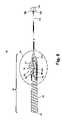
- FIG. 6is a sectional view taken along line 6 - 6 of FIG. 1 .
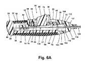
- FIG. 6Ais an enlarged sectional view of a front portion of the handle shown in FIG. 6 .
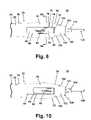
- FIG. 7is enlarged sectional view of the region labeled VII in FIG. 6 .
- FIG. 8is a top view of the marking apparatus shown in FIG. 1 .
- FIG. 8Ais a sectional view taken along line 8 A- 8 A of FIG. 8 .
- FIG. 9is a partial sectional view of the marking apparatus shown in FIG. 1 with the trigger in a second position and wherein the marking apparatus is inserted into a tissue mass.
- FIG. 9Ais an enlarged sectional view of a front portion of the handle shown in FIG. 9 .
- FIG. 10is a top view of the marking apparatus shown in FIG. 9 .
- FIG. 11is an enlarged view of the region labeled XI in FIG. 9 .
- the inventionaddresses the deficiencies of the prior art and provides a marking apparatus for subcutaneous placement of an imaging marker, wherein the marking apparatus comprises a trigger extending from a front portion of a handle such that a user can firmly grasp the marking apparatus in one hand while deploying the trigger with the same hand to accurately place the imaging marker at a predetermined site.
- a marking apparatus 10comprises a handle 20 that terminates at a tapered cap 100 and supports a trigger 60 operatively connected to a stylet 130 disposed inside a cannula 120 fixed to the cap 100 .
- the cap 100is described as being separate from the handle 20 . However, the cap 100 can be considered as part of the handle 20 and can even be integrated with the handle 20 .
- the handle 20comprises a front portion 22 , a rear portion 24 , with the front portion defining a distal end 26 for the handle and the rear portion 24 defining a proximal end 28 for the handle.
- the rear portion 24is elongated such that the user can grasp the handle 20 between multiple fingers 152 and a palm 158 or a thumb 156 of one hand 150 , as shown in FIGS. 3-5 and described in more detail hereinafter.
- the rear portion 24tapers outward near the distal end 28 to conform to the hand 150 and includes a texture, such as ribbing 30 , on its outer surface to facilitate gripping of the handle 20 .
- the front portion 22comprises a hollow, elongated body 34 having a circular region 35 and an arcuate region 37 with a pair of inwardly extending flanges 36 .
- Within the front portion 22is an internal cavity 38 defined on one side by a curved lower wall 40 to form a channel 39 .
- the flanges 36 and the cavity 38slidingly receive the trigger 60 , and the flanges 36 include axially spaced notches or detents that form a first set of catches 42 and a second set of catches 44 to retain the trigger 60 in a first position or a second position, respectively, as will be described in more detail hereinafter.
- the front portion 22further comprises diametrically opposed terminal clips 32 for mounting the cap 100 to the handle 20 .
- the relative lengths of the front portion 22 and the rear portion 24 of the handle 20can vary from that shown in the figures. The relative lengths can be selected based on factors such as comfort, ease of use, and size of the user's hand 150 . It is, however, necessary that the rear portion 24 is long enough for the user to grasp the handle 20 between the multiple fingers 152 and the palm 158 or the thumb 156 of the hand 150 and that the front portion 22 is long enough to slidably mount the trigger 60 .
- the finger or fingers 152refers to one or more appendage other than the thumb 156 extending from the hand 150 .
- the front portion 22 of the handle 20is surrounded by a grip 50 preferably composed of a resilient material.
- the grip 50comprises a proximal region 52 that encircles the circular region 35 , a distal region 54 that corresponds to the arcuate region 37 , and, within the distal region 54 , a slit 56 that is aligned with the flanges 36 to accommodate the trigger 60 through its range of motion.
- the outer diameter of the front portion 22 of the handle 20is less than that of the rear portion 24 , and the grip 50 is dimensioned, in at least the proximal region 52 , in accordance with the difference in the outer diameters so that the grip 50 is flush with the rear portion 24 of the of the handle 20 .
- the cap 100comprises a generally frustoconical body 102 with a hollow interior 106 and diametrically opposed apertures 104 sized to receive the clips 32 on the front portion 22 of the handle 20 .
- the body 102has a distal end 101 with a nipple 114 to which the cannula 120 is mounted and a proximal end 103 that abuts the front portion 22 of the handle 20 when the cap 100 is coupled with the handle 20 .
- the interior 106is partially defined by a flat upper wall 108 and a curved lower wall 110 .
- the flat upper wall 108is generally coplanar with an underside of the flanges 36 , and the curved lower wall 110 aligns with the curved lower wall 40 .
- the cap 100further comprises a detent 112 in the flat upper wall 108 for receiving a portion of the trigger 60 when the trigger 60 is in the second position, as will be described in more detail hereinafter.
- the cannula 120comprises a proximal end 124 mounted to the cap 100 , a distal end 122 defining a tip 126 , and a lumen 128 extending between the proximal and distal ends 124 and 122 .
- the tip 126is preferably pointed for insertion through skin and into the tissue mass; however, the tip 126 can optionally be blunt, for example, if the marking apparatus 10 is utilized with a trocar or the like.
- the cannula 120is a 17-gage (0.058 inch outer diameter) cannula, with an inner diameter ranging from 0.049 to 0.051 inches.
- the distal end 122 of the cannula 120can be designed for enhanced visibility using common imaging techniques, such as radiography, ultrasonography, and magnetic resonance imaging (MRI).
- the lumen 128 of the cannula 120slidingly receives the stylet 130 , which also comprises a proximal end 134 and a distal end 132 .
- the stylet 130is slidable from a ready position, wherein the distal end of the stylet 130 is spaced inwardly from the tip 126 to form a marker recess 129 , as best viewed in FIG.
- the stylet 130for housing an imaging marker 140 , to an extended position, wherein the distal end 132 of the stylet 130 is advanced towards the tip 126 and into the marker recess 129 to reduce the volume of the marker recess 129 and thereby eject the imaging marker 140 from the marker recess 129 , as shown in FIG. 11 .
- the stylet 130be sized in a manner such that when the stylet 130 is in the extended position, the stylet 130 extends to near the tip 126 of the cannula 120 to ensure complete ejection of the imaging marker 140 from the marker recess 129 . Movement of the stylet 130 is controlled by the trigger 60 .
- Imaging markersare well known in the medical device art, and any suitable imaging marker can be utilized with the marking apparatus 10 . Exemplary imaging markers are disclosed in U.S. Pat. No. 6,575,991, which is incorporated herein by reference in its entirety. Further, the type of imaging marker 140 is not limited by the size of the cannula 120 ; rather, the cannula 120 can be selected according to the type of imaging marker 140 .
- the trigger 60comprises a slide 62 , a button 76 disposed inside the slide 62 and movable relative to the slide 62 , and a biasing member 86 for biasing the button 76 upward within the slide 62 .
- the slide 62comprises a substantially rectangular and elongated base 64 and a finger or thumb rest 66 extending upward from the base 64 . Both sides of the rest 66 are undercut where the rest 66 meets the base 64 to form elongated channels 71 for slidingly mounting the trigger 60 to the flanges 36 .
- the base 64includes openings 70 located on each side of the rest 66 and underneath the channels 71 and a distal tab 72 sized to be received by the detent 112 in the cap 100 .
- the rest 66which is generally hollow for housing the button 76 , has a top surface 67 contoured to conform to the fingers 152 or the thumb 156 and formed with an elongated aperture 68 extending therethrough.
- the base 64further comprises a tubular stylet holder 74 on a side opposite the rest 66 .
- the stylet holder 74receives and fixedly mounts the stylet 130 to the trigger 60 .
- the button 76comprises a base 78 and a fin 80 extending upward from the base 78 and sized for receipt within the elongated aperture 68 in the rest 66 .
- the base 78includes a proximal, upwardly extending flange 84 and distal, upwardly extending projections 82 sized for receipt in the openings 70 in the slide 62 .
- the biasing member 86comprises a planar leaf spring 88 with a proximal, upwardly extending flange 90 and a pair of distal prongs 92 .
- the leaf spring 88 and the flange 90are oriented with an angle of less than 90 degrees therebetween. The angle is selected to optimize the amount of bias exerted against the button 76 .
- the angle between the leaf spring 88 and the flange 90is about 83 degrees.
- the slide 62houses the button 76 , and the biasing member 86 is mounted to the slide 62 by the flange 90 , which is inserted into a small cavity in the flange.
- the leaf spring 88abuts the base 78 of the button 76 and biases the button 76 into the slide 62 such that the base 78 of the button 76 coincides with the base 64 of the slide 62 , the fin 80 projects through the elongated aperture 68 , and the projections 82 project through the openings 70 and into the channels 71 .
- Downward force applied to the button 76forces the button 76 downward against the bias of the biasing member 86 .
- the button 76pivots about the flange 84 , which is also inserted into a small cavity in the slide 62 , the fin 80 is coincident with the top surface 67 of the rest 66 , and the projections 82 move downward within the openings 70 and no longer reside within the channels 71 .
- the flanges 36 on the handle 20reside in the channels 71 on the trigger 60 whereby the trigger 60 can slide distally and proximally relative to the handle 20 between the first position and the second position.
- the rest 66 of the slide 62 and the fin 80 of the button 76sit above the flanges 36 , and the remaining portions of the trigger 60 reside in the cavity 38 .
- the stylet holder 74is located in the channel 39 defined by the curved lower wall 40 of the handle front portion 22 .
- the tab 72is aligned with distal ends of the flanges 36 , and the biasing member 86 biases the projections 82 into the first set of catches 42 .
- the first set of catches 42hold the projections 82 to retain the trigger 60 in the first position and to prevent sliding movement of the trigger 60 .
- the tab 72is seated in the detent 112 in the cap 100 , and the biasing member 86 biases the projections 82 into the second set of catches 44 . Again, sliding movement of the trigger 60 is prevented because the projections 82 are held by the second set of catches 44 .
- the trigger 60To move the trigger 60 between the first and second positions, downward force must be applied to the button 76 to disengage the projections 82 from the catches 42 , 44 . Because the stylet 130 is fixedly mounted to and moves with the trigger 60 , the first and second positions of the trigger 60 correspond to the ready and extended positions of the stylet 130 .
- FIGS. 3-5because the trigger 60 extends from the front portion 22 of the handle 20 , the marking apparatus 10 can be firmly held in a hand 150 while simultaneously moving the trigger 60 from the first position to the second position with the same hand 150 .
- First, second, and third exemplary manners of holding the marking apparatusare illustrated in FIGS. 3-5 , respectively.
- the handle 20 of the marking apparatus 10is positioned between the fingers 152 , preferably three fingers 152 , and the palm 158 of the hand 150 , and the thumb 156 is situated on the trigger 60 for actuation thereof.
- An index finger 154preferably rests against the grip 50 for added stability.
- the marking apparatus 10is positioned between the fingers 152 , preferably three fingers 152 , and the thumb 156 of the hand 150 , and the index finger 154 is situated on the trigger 60 .
- the rear portion 24 of the handle 20can rest against a portion of the palm 158 for added stability.
- the third mannerinvolves rotating the marking apparatus 180 degrees relative to its position in the first and second manners.
- the marking apparatus 10is positioned between the fingers 152 , preferably three fingers 152 , and the palm 158 of the hand 150 , and the index finger 156 is situated on the trigger 60 .
- the thumb 156preferably rests against the grip 50 for added stability.
- the three manners described aboveare exemplary, and the particular manner in which the marking apparatus 10 is held and actuated with the hand 150 can be determined by the user in accordance with the user's preferences.
- the userholds the marking apparatus 10 in the hand 150 in a preferred manner, such as in one of the three manners described above and shown in FIGS. 3-5 .
- the marking apparatus 10is in a condition shown in FIGS. 2-6A , 8 , and 8 A, wherein the trigger 60 is in the first position and, thus, the stylet 130 is in the ready position with the imaging marker 140 disposed within the marker recess 129 .
- the marking apparatus 10is inserted into a tissue mass 160 , which is shown as a breast in FIG. 9 .
- the userguides the marking apparatus 10 to a predetermined site in the tissue mass 160 with the aid of an imaging system, such as an ultrasonic imaging system.
- an imaging systemsuch as an ultrasonic imaging system.
- the usercan hold an ultrasonic wand in a free hand (i.e., in a hand not holding the marking apparatus 10 ), and observe the location of the marking apparatus 10 in the tissue mass 160 on a video display monitor.
- the usermoves the trigger 60 from the first position to the second position with the thumb 156 or the index finger 154 of the hand 150 while holding the marking apparatus 10 between the fingers 152 and the palm 158 or the fingers 152 and the thumb 156 of the same hand 150 .
- the userdepresses the fin 80 of the button 76 to push the button 76 against the bias of the biasing member 86 .
- the projections 82move downward within the openings 70 and no longer reside within the first set of catches 42 or the channels 71 and, therefore, no longer prevent sliding movement of the trigger 60 .
- the usermaintains the downward force and applies a distal force to the trigger 60 to slide the trigger towards the second position.
- the tab 72rides along the flat upper wall of the cap 100 , and the projections 82 ride along the underside of the flanges 36 .
- the stylet 130advances towards the tip 126 of the cannula 120 and into the marker recess 129 to thereby reduce the volume of the marker recess 129 and simultaneously push the imaging marker 140 distally towards the predetermined site.
- the stylet 130achieves the extended position for complete ejection of the imaging marker 140 from the marker recess 129 .
- the tab 72is received within the detent 112 , the projections 82 are aligned with the second set of catches 44 , and further distal movement of the trigger 60 is prevented by the cap 100 .
- the button 76moves upward within the rest 66 under the bias of the biasing member 86 , and the projections 82 mate with the second set of catches 44 to retain the trigger 60 in the second position.
- the userthen removes the marking apparatus 10 from the tissue mass with the hand 150 . Because the trigger 60 is secured in the second position, accidental movement of the stylet 130 relative to the cannula 120 is prevented during withdrawal of the marking apparatus 10 .
- the location of the trigger 60enables the user to firmly grasp the marking apparatus 10 in the hand 150 and simultaneously deploy the trigger 60 with the same hand 150 for ejection of the imaging marker 140 at the predetermined site.
- the location of the trigger 60 on the handle 20gives the user a significant amount of control when positioning the tip 126 of the cannula 120 .
- any movement of the handle 20 external to the tissue mass 160induces similar movement of the cannula 120 inside the tissue mass 160 .
- the marking apparatus 10effectively pivots about the point where the marking apparatus 10 is inserted into the tissue mass 160 .
- the distance from the pivot point to the trigger 60is smaller when compared to prior art marking apparatuses having the trigger disposed at a proximal end of a handle 20 . As the distance between the trigger 60 and the pivot point decreases, the ability of the user to keep the marking apparatus 10 steady or to control movement of the marking apparatus 10 increases.
- the exemplary hand positions enabled by the front triggerare inherently more natural and sustainable than what was possible with prior art rear trigger devices.
- the practitionergrips the handle in the same manner that one would grip a knife for stabbing so that the practitioner's thumb would be able to actuate the rear trigger.
- Such a gripis best suited for moving the device distally to place the device within the tissue mass.
- Most practitionersfind it difficult and awkward to accurately laterally insert the device using the prior art rear trigger devices.
- the inventive devicepermits the user to comfortably and accurately insert the cannula into the tissue mass and hold the device in the inserted position with great stability while the practitioner positions the tip of the cannula using the imaging system.
- the shape of the inventive deviceenhances the stability and positioning by providing a relative long handle area over which the user can apply opposing compressive forces between the fingers and the palm or the extended thumb.
Landscapes
- Health & Medical Sciences (AREA)
- Life Sciences & Earth Sciences (AREA)
- General Health & Medical Sciences (AREA)
- Veterinary Medicine (AREA)
- Heart & Thoracic Surgery (AREA)
- Surgery (AREA)
- Biomedical Technology (AREA)
- Animal Behavior & Ethology (AREA)
- Engineering & Computer Science (AREA)
- Public Health (AREA)
- Anesthesiology (AREA)
- Nuclear Medicine, Radiotherapy & Molecular Imaging (AREA)
- Oral & Maxillofacial Surgery (AREA)
- Pathology (AREA)
- Hematology (AREA)
- Medical Informatics (AREA)
- Molecular Biology (AREA)
- Surgical Instruments (AREA)
Abstract
Description
Claims (22)
Priority Applications (3)
| Application Number | Priority Date | Filing Date | Title |
|---|---|---|---|
| US10/906,106US7577473B2 (en) | 2005-02-03 | 2005-02-03 | Apparatus for subcutaneous placement of an imaging marker |
| CA2534722ACA2534722C (en) | 2005-02-03 | 2006-01-31 | Apparatus for subcutaenous placement of an imaging marker |
| EP06101181AEP1688100B1 (en) | 2005-02-03 | 2006-02-02 | Apparatus for subcutaneous placement of an imaging marker |
Applications Claiming Priority (1)
| Application Number | Priority Date | Filing Date | Title |
|---|---|---|---|
| US10/906,106US7577473B2 (en) | 2005-02-03 | 2005-02-03 | Apparatus for subcutaneous placement of an imaging marker |
Publications (2)
| Publication Number | Publication Date |
|---|---|
| US20060184090A1 US20060184090A1 (en) | 2006-08-17 |
| US7577473B2true US7577473B2 (en) | 2009-08-18 |
Family
ID=36121689
Family Applications (1)
| Application Number | Title | Priority Date | Filing Date |
|---|---|---|---|
| US10/906,106Active2025-11-13US7577473B2 (en) | 2005-02-03 | 2005-02-03 | Apparatus for subcutaneous placement of an imaging marker |
Country Status (3)
| Country | Link |
|---|---|
| US (1) | US7577473B2 (en) |
| EP (1) | EP1688100B1 (en) |
| CA (1) | CA2534722C (en) |
Cited By (33)
| Publication number | Priority date | Publication date | Assignee | Title |
|---|---|---|---|---|
| US7819820B2 (en) | 2003-11-17 | 2010-10-26 | Bard Peripheral Vascular, Inc. | Self contained, self piercing, side-expelling marking apparatus |
| US20100280367A1 (en)* | 2009-04-30 | 2010-11-04 | Ducharme Richard W | System and method for fiducial deployment |
| US20110196433A1 (en)* | 2010-02-08 | 2011-08-11 | Kleiner Jeffrey B | Method and System for Identification of a Center of a Vertebral Disc Space and Corresponding Central Axis of a Spinal Column |
| US8052708B2 (en) | 1999-06-17 | 2011-11-08 | Bard Peripheral Vascular, Inc. | Apparatus for the percutaneous marking of a lesion |
| US8064987B2 (en) | 2006-10-23 | 2011-11-22 | C. R. Bard, Inc. | Breast marker |
| US8177792B2 (en) | 2002-06-17 | 2012-05-15 | Senorx, Inc. | Plugged tip delivery tube for marker placement |
| US8311610B2 (en) | 2008-01-31 | 2012-11-13 | C. R. Bard, Inc. | Biopsy tissue marker |
| US8361082B2 (en) | 1999-02-02 | 2013-01-29 | Senorx, Inc. | Marker delivery device with releasable plug |
| US8401622B2 (en) | 2006-12-18 | 2013-03-19 | C. R. Bard, Inc. | Biopsy marker with in situ-generated imaging properties |
| US8419656B2 (en) | 2004-11-22 | 2013-04-16 | Bard Peripheral Vascular, Inc. | Post decompression marker introducer system |
| US8486028B2 (en) | 2005-10-07 | 2013-07-16 | Bard Peripheral Vascular, Inc. | Tissue marking apparatus having drug-eluting tissue marker |
| US8498693B2 (en) | 1999-02-02 | 2013-07-30 | Senorx, Inc. | Intracorporeal marker and marker delivery device |
| US8634899B2 (en) | 2003-11-17 | 2014-01-21 | Bard Peripheral Vascular, Inc. | Multi mode imaging marker |
| US8668737B2 (en) | 1997-10-10 | 2014-03-11 | Senorx, Inc. | Tissue marking implant |
| US8670818B2 (en) | 2008-12-30 | 2014-03-11 | C. R. Bard, Inc. | Marker delivery device for tissue marker placement |
| USD715442S1 (en) | 2013-09-24 | 2014-10-14 | C. R. Bard, Inc. | Tissue marker for intracorporeal site identification |
| USD715942S1 (en) | 2013-09-24 | 2014-10-21 | C. R. Bard, Inc. | Tissue marker for intracorporeal site identification |
| USD716450S1 (en) | 2013-09-24 | 2014-10-28 | C. R. Bard, Inc. | Tissue marker for intracorporeal site identification |
| USD716451S1 (en) | 2013-09-24 | 2014-10-28 | C. R. Bard, Inc. | Tissue marker for intracorporeal site identification |
| US9149341B2 (en) | 1999-02-02 | 2015-10-06 | Senorx, Inc | Deployment of polysaccharide markers for treating a site within a patient |
| US9327061B2 (en) | 2008-09-23 | 2016-05-03 | Senorx, Inc. | Porous bioabsorbable implant |
| US9522264B2 (en) | 2013-02-26 | 2016-12-20 | Cook Medical Technologies Llc | Ratchet-slide handle and system for fiducial deployment |
| US9579077B2 (en) | 2006-12-12 | 2017-02-28 | C.R. Bard, Inc. | Multiple imaging mode tissue marker |
| US9770262B2 (en) | 2014-06-09 | 2017-09-26 | Cook Medical Technologies Llc | Screw-driven handles and systems for fiducial deployment |
| US9808320B2 (en) | 2010-02-08 | 2017-11-07 | Jeffrey B. Kleiner | Method and system for identification of a center of a patient's body part |
| US9820824B2 (en) | 1999-02-02 | 2017-11-21 | Senorx, Inc. | Deployment of polysaccharide markers for treating a site within a patent |
| US10123848B2 (en) | 2014-12-03 | 2018-11-13 | Cook Medical Technologies Llc | EUS fiducial needle stylet handle assembly |
| US10258373B2 (en) | 2011-06-28 | 2019-04-16 | Cook Medical Technologies Llc | Fiducial deployment needle system |
| US10342635B2 (en) | 2005-04-20 | 2019-07-09 | Bard Peripheral Vascular, Inc. | Marking device with retractable cannula |
| US10363407B2 (en) | 2014-06-16 | 2019-07-30 | Cook Medical Technologies Llc | Plunger-driven collet handle and system for fiducial deployment |
| US11064995B2 (en) | 2019-05-02 | 2021-07-20 | Arthrex, Inc. | Surgical device with trigger operated needle |
| USD1030045S1 (en)* | 2021-04-13 | 2024-06-04 | Cornell University | Catheter assembly |
| US12226267B2 (en) | 2021-12-15 | 2025-02-18 | Smith & Nephew, Inc. | Methods and systems for fiducial marker deployment in medical procedures |
Families Citing this family (9)
| Publication number | Priority date | Publication date | Assignee | Title |
|---|---|---|---|---|
| US10149700B2 (en)* | 2013-08-12 | 2018-12-11 | Jan R. Lau | 3 dimensional simultaneous multiple core biopsy or fiducial marker placement device and methods |
| US9775698B2 (en) | 2015-01-23 | 2017-10-03 | Spinal Singularity, Inc. | Urinary prosthesis systems |
| US11510765B2 (en) | 2015-01-23 | 2022-11-29 | Spinal Singularity, Inc. | Extended-use catheters |
| US10675435B2 (en) | 2015-04-01 | 2020-06-09 | Spinal Singularity, Inc. | Extended-use valved urinary catheter |
| US11065093B2 (en) | 2015-01-23 | 2021-07-20 | Spinal Singularity, Inc. | Catheter mating devices |
| US10751506B2 (en) | 2015-04-01 | 2020-08-25 | Spinal Singularity, Inc. | Catheters and catheter mating devices and systems |
| CN109069169B (en)* | 2016-05-06 | 2021-07-20 | 波士顿科学医学有限公司 | Medical systems, devices and related methods |
| US11628271B2 (en) | 2019-06-10 | 2023-04-18 | Spinal Singularity, Inc. | Urinary catheter |
| AU2023272953A1 (en)* | 2022-05-20 | 2024-12-05 | Merit Medical Systems, Inc. | Marker inserter |
Citations (20)
| Publication number | Priority date | Publication date | Assignee | Title |
|---|---|---|---|---|
| US2907327A (en) | 1957-02-08 | 1959-10-06 | Pfizer & Co C | Pellet implanter |
| US4820267A (en) | 1985-02-19 | 1989-04-11 | Endocon, Inc. | Cartridge injector for pellet medicaments |
| US4994028A (en) | 1987-03-18 | 1991-02-19 | Endocon, Inc. | Injector for inplanting multiple pellet medicaments |
| US5250026A (en) | 1992-05-27 | 1993-10-05 | Destron/Idi, Inc. | Adjustable precision transponder injector |
| US5353804A (en) | 1990-09-18 | 1994-10-11 | Peb Biopsy Corporation | Method and device for percutaneous exisional breast biopsy |
| US5542915A (en)* | 1992-08-12 | 1996-08-06 | Vidamed, Inc. | Thermal mapping catheter with ultrasound probe |
| US5842999A (en) | 1996-07-31 | 1998-12-01 | C.R. Bard, Inc. | Automated tissue sampling device |
| US5879357A (en) | 1995-10-20 | 1999-03-09 | United States Surgical Corporation | Apparatus for marking tissue location |
| EP0966925A1 (en) | 1998-06-26 | 1999-12-29 | Ethicon Endo-Surgery, Inc. | Applier for implantable surgical marker |
| US6142955A (en) | 1997-09-19 | 2000-11-07 | United States Surgical Corporation | Biopsy apparatus and method |
| US6190350B1 (en) | 1997-12-29 | 2001-02-20 | Alza Corporation | Implanter device for subcutaneous implants |
| US6312429B1 (en) | 1998-09-01 | 2001-11-06 | Senorx, Inc. | Electrosurgical lesion location device |
| US20020045842A1 (en) | 2000-10-16 | 2002-04-18 | Van Bladel Kevin H. | Device for biopsy of tumors |
| US20020095204A1 (en) | 2001-01-18 | 2002-07-18 | Thompson Paul J. | Grip for stent delivery system |
| US6551253B2 (en) | 1997-09-12 | 2003-04-22 | Imagyn Medical Technologies | Incisional breast biopsy device |
| US6575991B1 (en)* | 1999-06-17 | 2003-06-10 | Inrad, Inc. | Apparatus for the percutaneous marking of a lesion |
| US6638234B2 (en) | 1998-03-03 | 2003-10-28 | Senorx, Inc. | Sentinel node location and biopsy |
| US20040127765A1 (en) | 2002-12-30 | 2004-07-01 | Keith Seiler | Apparatuses and methods for percutaneously implanting objects in patients |
| US6766186B1 (en) | 1999-06-16 | 2004-07-20 | C. R. Bard, Inc. | Post biospy tissue marker and method of use |
| US20040162574A1 (en) | 2001-08-03 | 2004-08-19 | Viola Frank J. | Tissue marking apparatus and method |
- 2005
- 2005-02-03USUS10/906,106patent/US7577473B2/enactiveActive
- 2006
- 2006-01-31CACA2534722Apatent/CA2534722C/enactiveActive
- 2006-02-02EPEP06101181Apatent/EP1688100B1/ennot_activeCeased
Patent Citations (21)
| Publication number | Priority date | Publication date | Assignee | Title |
|---|---|---|---|---|
| US2907327A (en) | 1957-02-08 | 1959-10-06 | Pfizer & Co C | Pellet implanter |
| US4820267A (en) | 1985-02-19 | 1989-04-11 | Endocon, Inc. | Cartridge injector for pellet medicaments |
| US4994028A (en) | 1987-03-18 | 1991-02-19 | Endocon, Inc. | Injector for inplanting multiple pellet medicaments |
| US5353804A (en) | 1990-09-18 | 1994-10-11 | Peb Biopsy Corporation | Method and device for percutaneous exisional breast biopsy |
| US5250026A (en) | 1992-05-27 | 1993-10-05 | Destron/Idi, Inc. | Adjustable precision transponder injector |
| US5542915A (en)* | 1992-08-12 | 1996-08-06 | Vidamed, Inc. | Thermal mapping catheter with ultrasound probe |
| US5879357A (en) | 1995-10-20 | 1999-03-09 | United States Surgical Corporation | Apparatus for marking tissue location |
| US5842999A (en) | 1996-07-31 | 1998-12-01 | C.R. Bard, Inc. | Automated tissue sampling device |
| US6551253B2 (en) | 1997-09-12 | 2003-04-22 | Imagyn Medical Technologies | Incisional breast biopsy device |
| US6142955A (en) | 1997-09-19 | 2000-11-07 | United States Surgical Corporation | Biopsy apparatus and method |
| US6190350B1 (en) | 1997-12-29 | 2001-02-20 | Alza Corporation | Implanter device for subcutaneous implants |
| US6638234B2 (en) | 1998-03-03 | 2003-10-28 | Senorx, Inc. | Sentinel node location and biopsy |
| US6261302B1 (en) | 1998-06-26 | 2001-07-17 | Ethicon Endo-Surgery, Inc. | Applier for implantable surgical marker |
| EP0966925A1 (en) | 1998-06-26 | 1999-12-29 | Ethicon Endo-Surgery, Inc. | Applier for implantable surgical marker |
| US6312429B1 (en) | 1998-09-01 | 2001-11-06 | Senorx, Inc. | Electrosurgical lesion location device |
| US6766186B1 (en) | 1999-06-16 | 2004-07-20 | C. R. Bard, Inc. | Post biospy tissue marker and method of use |
| US6575991B1 (en)* | 1999-06-17 | 2003-06-10 | Inrad, Inc. | Apparatus for the percutaneous marking of a lesion |
| US20020045842A1 (en) | 2000-10-16 | 2002-04-18 | Van Bladel Kevin H. | Device for biopsy of tumors |
| US20020095204A1 (en) | 2001-01-18 | 2002-07-18 | Thompson Paul J. | Grip for stent delivery system |
| US20040162574A1 (en) | 2001-08-03 | 2004-08-19 | Viola Frank J. | Tissue marking apparatus and method |
| US20040127765A1 (en) | 2002-12-30 | 2004-07-01 | Keith Seiler | Apparatuses and methods for percutaneously implanting objects in patients |
Cited By (58)
| Publication number | Priority date | Publication date | Assignee | Title |
|---|---|---|---|---|
| US8668737B2 (en) | 1997-10-10 | 2014-03-11 | Senorx, Inc. | Tissue marking implant |
| US9039763B2 (en) | 1997-10-10 | 2015-05-26 | Senorx, Inc. | Tissue marking implant |
| US8361082B2 (en) | 1999-02-02 | 2013-01-29 | Senorx, Inc. | Marker delivery device with releasable plug |
| US9861294B2 (en) | 1999-02-02 | 2018-01-09 | Senorx, Inc. | Marker delivery device with releasable plug |
| US9820824B2 (en) | 1999-02-02 | 2017-11-21 | Senorx, Inc. | Deployment of polysaccharide markers for treating a site within a patent |
| US9044162B2 (en) | 1999-02-02 | 2015-06-02 | Senorx, Inc. | Marker delivery device with releasable plug |
| US9149341B2 (en) | 1999-02-02 | 2015-10-06 | Senorx, Inc | Deployment of polysaccharide markers for treating a site within a patient |
| US10172674B2 (en) | 1999-02-02 | 2019-01-08 | Senorx, Inc. | Intracorporeal marker and marker delivery device |
| US8498693B2 (en) | 1999-02-02 | 2013-07-30 | Senorx, Inc. | Intracorporeal marker and marker delivery device |
| US10463446B2 (en) | 1999-06-17 | 2019-11-05 | Bard Peripheral Vascular, Inc. | Apparatus for the percutaneous marking of a lesion |
| US8052708B2 (en) | 1999-06-17 | 2011-11-08 | Bard Peripheral Vascular, Inc. | Apparatus for the percutaneous marking of a lesion |
| US8177792B2 (en) | 2002-06-17 | 2012-05-15 | Senorx, Inc. | Plugged tip delivery tube for marker placement |
| US8784433B2 (en) | 2002-06-17 | 2014-07-22 | Senorx, Inc. | Plugged tip delivery tube for marker placement |
| US10813716B2 (en) | 2002-11-18 | 2020-10-27 | Bard Peripheral Vascular, Inc. | Self-contained, self-piercing, side-expelling marking apparatus |
| US9848956B2 (en) | 2002-11-18 | 2017-12-26 | Bard Peripheral Vascular, Inc. | Self-contained, self-piercing, side-expelling marking apparatus |
| US8634899B2 (en) | 2003-11-17 | 2014-01-21 | Bard Peripheral Vascular, Inc. | Multi mode imaging marker |
| US7819820B2 (en) | 2003-11-17 | 2010-10-26 | Bard Peripheral Vascular, Inc. | Self contained, self piercing, side-expelling marking apparatus |
| US8419656B2 (en) | 2004-11-22 | 2013-04-16 | Bard Peripheral Vascular, Inc. | Post decompression marker introducer system |
| US11278370B2 (en) | 2005-04-20 | 2022-03-22 | Bard Peripheral Vascular, Inc. | Marking device with retractable cannula |
| US10357328B2 (en) | 2005-04-20 | 2019-07-23 | Bard Peripheral Vascular, Inc. and Bard Shannon Limited | Marking device with retractable cannula |
| US10342635B2 (en) | 2005-04-20 | 2019-07-09 | Bard Peripheral Vascular, Inc. | Marking device with retractable cannula |
| US8486028B2 (en) | 2005-10-07 | 2013-07-16 | Bard Peripheral Vascular, Inc. | Tissue marking apparatus having drug-eluting tissue marker |
| US8437834B2 (en) | 2006-10-23 | 2013-05-07 | C. R. Bard, Inc. | Breast marker |
| US8064987B2 (en) | 2006-10-23 | 2011-11-22 | C. R. Bard, Inc. | Breast marker |
| US11471244B2 (en) | 2006-12-12 | 2022-10-18 | C.R. Bard, Inc. | Multiple imaging mode tissue marker |
| US9901415B2 (en) | 2006-12-12 | 2018-02-27 | C. R. Bard, Inc. | Multiple imaging mode tissue marker |
| US10682200B2 (en) | 2006-12-12 | 2020-06-16 | C. R. Bard, Inc. | Multiple imaging mode tissue marker |
| US9579077B2 (en) | 2006-12-12 | 2017-02-28 | C.R. Bard, Inc. | Multiple imaging mode tissue marker |
| US9042965B2 (en) | 2006-12-18 | 2015-05-26 | C. R. Bard, Inc. | Biopsy marker with in situ-generated imaging properties |
| US8401622B2 (en) | 2006-12-18 | 2013-03-19 | C. R. Bard, Inc. | Biopsy marker with in situ-generated imaging properties |
| US8311610B2 (en) | 2008-01-31 | 2012-11-13 | C. R. Bard, Inc. | Biopsy tissue marker |
| US9327061B2 (en) | 2008-09-23 | 2016-05-03 | Senorx, Inc. | Porous bioabsorbable implant |
| US11833275B2 (en) | 2008-09-23 | 2023-12-05 | Senorx, Inc. | Porous bioabsorbable implant |
| US10786604B2 (en) | 2008-09-23 | 2020-09-29 | Senorx, Inc. | Porous bioabsorbable implant |
| US10258428B2 (en) | 2008-12-30 | 2019-04-16 | C. R. Bard, Inc. | Marker delivery device for tissue marker placement |
| US11779431B2 (en) | 2008-12-30 | 2023-10-10 | C. R. Bard, Inc. | Marker delivery device for tissue marker placement |
| US8670818B2 (en) | 2008-12-30 | 2014-03-11 | C. R. Bard, Inc. | Marker delivery device for tissue marker placement |
| US20100280367A1 (en)* | 2009-04-30 | 2010-11-04 | Ducharme Richard W | System and method for fiducial deployment |
| US9042964B2 (en) | 2009-04-30 | 2015-05-26 | Cook Medical Technologies Llc | System and method for fiducial deployment via slotted needle |
| US9005214B2 (en) | 2010-02-08 | 2015-04-14 | Jeffrey B. Kleiner | Method and system for identification of a center of a vertebral disc space and corresponding central axis of a spinal column |
| US20110196433A1 (en)* | 2010-02-08 | 2011-08-11 | Kleiner Jeffrey B | Method and System for Identification of a Center of a Vertebral Disc Space and Corresponding Central Axis of a Spinal Column |
| US9808320B2 (en) | 2010-02-08 | 2017-11-07 | Jeffrey B. Kleiner | Method and system for identification of a center of a patient's body part |
| US9271849B2 (en) | 2010-02-08 | 2016-03-01 | Jeffrey B. Kleiner | Method and system for identification of a center of a patient's body part |
| US9585728B2 (en) | 2010-02-08 | 2017-03-07 | Jeffrey B. Kleiner | Method and system for identification of a center of a patient's body part |
| US8690887B2 (en) | 2010-02-08 | 2014-04-08 | Jeffrey B. Kleiner | Method and system for identification of a center of a vertebral disc space and corresponding central axis of a spinal column |
| US10258373B2 (en) | 2011-06-28 | 2019-04-16 | Cook Medical Technologies Llc | Fiducial deployment needle system |
| US10292786B2 (en) | 2013-02-26 | 2019-05-21 | Cook Medical Technologies Llc | Ratchet-slide handle and system for fiducial deployment |
| US9522264B2 (en) | 2013-02-26 | 2016-12-20 | Cook Medical Technologies Llc | Ratchet-slide handle and system for fiducial deployment |
| USD716450S1 (en) | 2013-09-24 | 2014-10-28 | C. R. Bard, Inc. | Tissue marker for intracorporeal site identification |
| USD715942S1 (en) | 2013-09-24 | 2014-10-21 | C. R. Bard, Inc. | Tissue marker for intracorporeal site identification |
| USD716451S1 (en) | 2013-09-24 | 2014-10-28 | C. R. Bard, Inc. | Tissue marker for intracorporeal site identification |
| USD715442S1 (en) | 2013-09-24 | 2014-10-14 | C. R. Bard, Inc. | Tissue marker for intracorporeal site identification |
| US9770262B2 (en) | 2014-06-09 | 2017-09-26 | Cook Medical Technologies Llc | Screw-driven handles and systems for fiducial deployment |
| US10363407B2 (en) | 2014-06-16 | 2019-07-30 | Cook Medical Technologies Llc | Plunger-driven collet handle and system for fiducial deployment |
| US10123848B2 (en) | 2014-12-03 | 2018-11-13 | Cook Medical Technologies Llc | EUS fiducial needle stylet handle assembly |
| US11064995B2 (en) | 2019-05-02 | 2021-07-20 | Arthrex, Inc. | Surgical device with trigger operated needle |
| USD1030045S1 (en)* | 2021-04-13 | 2024-06-04 | Cornell University | Catheter assembly |
| US12226267B2 (en) | 2021-12-15 | 2025-02-18 | Smith & Nephew, Inc. | Methods and systems for fiducial marker deployment in medical procedures |
Also Published As
| Publication number | Publication date |
|---|---|
| CA2534722A1 (en) | 2006-08-03 |
| EP1688100B1 (en) | 2011-12-21 |
| CA2534722C (en) | 2013-12-10 |
| EP1688100A1 (en) | 2006-08-09 |
| US20060184090A1 (en) | 2006-08-17 |
Similar Documents
| Publication | Publication Date | Title |
|---|---|---|
| US7577473B2 (en) | Apparatus for subcutaneous placement of an imaging marker | |
| US20220151727A1 (en) | Marking device with retractable cannula | |
| US10813716B2 (en) | Self-contained, self-piercing, side-expelling marking apparatus | |
| JP4799905B2 (en) | Positioning jig for MRI biopsy device | |
| US8758369B2 (en) | Biopsy devices and methods | |
| US5830152A (en) | Pencil-grip fine needle aspiration syringe holder | |
| US8961558B2 (en) | Treatment tool for endoscope | |
| US20250295396A1 (en) | Biopsy device arming mechanism | |
| US20130060161A1 (en) | Coaxial needle assembly | |
| US10779795B2 (en) | Low profile endocavity needle guides | |
| EP1694213A2 (en) | Cytology collection device | |
| US20170143316A1 (en) | Method for excising core tissue sample | |
| JP2024125645A (en) | Lancing device | |
| US20040204733A1 (en) | Surgical needle assembly comprising a stopper | |
| HK1232757A1 (en) | Introducer for biopsy device |
Legal Events
| Date | Code | Title | Description |
|---|---|---|---|
| AS | Assignment | Owner name:INRAD, INC., MICHIGAN Free format text:ASSIGNMENT OF ASSIGNORS INTEREST;ASSIGNORS:DAVIS, RICHARD E.;GOOSEN, RYAN L.;FIELD, STEVEN E.;REEL/FRAME:015641/0319 Effective date:20050103 | |
| AS | Assignment | Owner name:INRAD, INC., MICHIGAN Free format text:ASSIGNMENT OF ASSIGNORS INTEREST;ASSIGNOR:CHESBROUGH, RICHARD M.;REEL/FRAME:019395/0149 Effective date:20070605 | |
| AS | Assignment | Owner name:BARD SHANNON LIMITED, NETHERLANDS Free format text:ASSIGNMENT OF ASSIGNORS INTEREST;ASSIGNOR:INRAD, INC.;REEL/FRAME:019628/0205 Effective date:20070613 Owner name:BARD PERIPHERAL VASCULAR, INC., ARIZONA Free format text:ASSIGNMENT OF ASSIGNORS INTEREST;ASSIGNOR:INRAD, INC.;REEL/FRAME:019628/0205 Effective date:20070613 | |
| STCF | Information on status: patent grant | Free format text:PATENTED CASE | |
| FPAY | Fee payment | Year of fee payment:4 | |
| FPAY | Fee payment | Year of fee payment:8 | |
| MAFP | Maintenance fee payment | Free format text:PAYMENT OF MAINTENANCE FEE, 12TH YEAR, LARGE ENTITY (ORIGINAL EVENT CODE: M1553); ENTITY STATUS OF PATENT OWNER: LARGE ENTITY Year of fee payment:12 |