US7577284B2 - Optical detection of dental caries - Google Patents
Optical detection of dental cariesDownload PDFInfo
- Publication number
- US7577284B2 US7577284B2US11/408,360US40836006AUS7577284B2US 7577284 B2US7577284 B2US 7577284B2US 40836006 AUS40836006 AUS 40836006AUS 7577284 B2US7577284 B2US 7577284B2
- Authority
- US
- United States
- Prior art keywords
- tooth
- image
- light
- fluorescence
- image data
- Prior art date
- Legal status (The legal status is an assumption and is not a legal conclusion. Google has not performed a legal analysis and makes no representation as to the accuracy of the status listed.)
- Expired - Fee Related, expires
Links
Images


Classifications
- A—HUMAN NECESSITIES
- A61—MEDICAL OR VETERINARY SCIENCE; HYGIENE
- A61B—DIAGNOSIS; SURGERY; IDENTIFICATION
- A61B5/00—Measuring for diagnostic purposes; Identification of persons
- A61B5/0059—Measuring for diagnostic purposes; Identification of persons using light, e.g. diagnosis by transillumination, diascopy, fluorescence
- A61B5/0082—Measuring for diagnostic purposes; Identification of persons using light, e.g. diagnosis by transillumination, diascopy, fluorescence adapted for particular medical purposes
- A61B5/0088—Measuring for diagnostic purposes; Identification of persons using light, e.g. diagnosis by transillumination, diascopy, fluorescence adapted for particular medical purposes for oral or dental tissue
Definitions
- This inventiongenerally relates to methods and apparatus for dental imaging and more particularly relates to an improved method for caries detection on all surfaces, including interproximal surface, using light fluorescence and reflectance.
- QLFquantitative light-induced fluorescence
- U.S. Patent Application Publication No. 2004/0202356(Stookey et al.) describes mathematical processing of spectral changes in fluorescence in order to detect caries in different stages with improved accuracy. Acknowledging the difficulty of early detection when using spectral fluorescence measurements, the '2356 Stookey et al. disclosure describes approaches for enhancing the spectral values obtained, effecting a transformation of the spectral data that is adapted to the spectral response of the camera that obtains the fluorescent image.
- interproximal cariesthat is, caries occurring on surfaces along the gap between adjacent teeth.
- interproximal areascan be considerably more difficult to illuminate and to view.
- the excitation illumination that causes the fluorescencecan be directed to the tooth from any of a range of angles within the same plane, that is, the plane containing the normals to the buccal, occlusal, and lingual surfaces, with little or no perceptible improvement between illumination at one angular orientation and another.
- Interproximal cariesis a highly prevalent form of dental caries that can be difficult to detect. Although imaging solutions such as those using fluorescence generation have shown some utility for detection of caries over areas of the tooth that can be more easily viewed, these solutions have shown little success in detecting interproximal caries. Thus, it can be seen that there is a need for a non-invasive, non-ionizing imaging method for caries detection that offers improved accuracy for detection of caries in its earlier stages and of interproximal caries.
- the present inventionprovides a method for caries detection comprising:
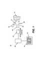
- FIG. 1is a schematic block diagram of an imaging apparatus for caries detection according to one embodiment
- FIG. 2is a schematic block diagram of an imaging apparatus for caries detection according to an alternate embodiment
- FIG. 3is a schematic block diagram of an imaging apparatus for caries detection according to an alternate embodiment using a beamsplitter
- FIG. 4Ais a schematic block diagram of an imaging apparatus for caries detection according to an alternate embodiment using polarized light
- FIG. 4Bis a schematic block diagram of an imaging apparatus for caries detection according to an alternate embodiment using a polarizing beamsplitter to provide polarized light;
- FIG. 5is a view showing the process for combining dental image data to generate a fluorescence image with reflectance enhancement according to the present invention
- FIG. 6is a composite view showing the contrast improvement of the present invention in a side-by-side comparison with conventional visual and fluorescence methods
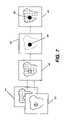
- FIG. 7is a block diagram showing a sequence of image processing for generating an enhanced threshold image according to one embodiment
- FIGS. 8A and 8Bare perspective views showing a camera obtaining an image of an interproximal area at two different illumination angles, according to the method of the present invention.
- FIG. 9is a perspective view of a camera arrangement for providing illumination from different angles.
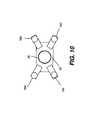
- FIG. 10is a plan view of the front of a camera such as that shown in FIG. 9 ;
- FIGS. 11A and 11Billustrate angled illumination from one side of the camera and the resulting FIRE image
- FIGS. 12A and 12Billustrate angled illumination from another side of the camera and the resulting FIRE image
- FIGS. 13A and 13Billustrate angled illumination from both sides of the camera and the resulting FIRE image
- FIG. 14is a flow chart of the work flow for caries detection using the method of the present invention.
- FIG. 15shows a display interface for dental practitioner to make caries diagnosis
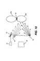
- FIG. 16shows an alternate embodiment in which only one light source is used to provide the illumination light from both angles, utilizing a movable mirror.
- fluorescencecan be used to detect dental caries using either of two characteristic responses: First, excitation by a blue light source causes healthy tooth tissue to fluoresce in the green spectrum. Secondly, excitation by a red light source can cause bacterial by-products, such as those indicating caries, to fluoresce in the red spectrum.
- reflectanceIn order for an understanding of how light is used in the present invention, it is important to give more precise definition to the terms “reflectance” and “back-scattering” as they are used in biomedical applications in general and, more particularly, in the method and apparatus of the present invention.
- reflectanceIn broadest optical parlance, reflectance generally denotes the sum total of both specular reflectance and scattered reflectance. (Specular reflection is that component of the excitation light that is reflected by the tooth surface at the same angle as the incident angle.)
- specular component of reflectanceis of no interest and is, instead, generally detrimental to obtaining an image or measurement from a sample.
- the component of reflectance that is of interest for the present applicationis from back-scattered light only. Specular reflectance must be blocked or otherwise removed from the imaging path.
- the term “back-scattered reflectance”is used in the present application to denote the component of reflectance that is of interest. “Back-scattered reflectance” is defined as that component of the excitation light that is elastically back-scattered over a wide range of angles by the illuminated tooth structure.
- “Reflectance image” datarefers to image data obtained from back-scattered reflectance only, since specular reflectance is blocked or kept to a minimum. In the scientific literature, back-scattered reflectance may also be referred to as back-reflectance or simply as backscattering. Back-scattered reflectance is at the same wavelength as the excitation light.
- the present inventiontakes advantage of the observed back-scattering behavior for incipient caries and uses this effect, in combination with fluorescence effects described previously in the background section, to provide an improved capability for dental imaging to detect caries.
- the inventive techniquehereafter referred to as fluorescence imaging with reflectance enhancement (FIRE)
- FIREfluorescence imaging with reflectance enhancement
- FIRE detectioncan be accurate at an earlier stage of caries infection than has been exhibited using existing fluorescence approaches that measure fluorescence alone.
- the FIRE detection methodscan be used to obtain more effective detection of interproximal caries than has been previously available.
- a light source 12directs an incident light, at a blue wavelength range or other suitable wavelength range, toward tooth 20 through an optional lens 14 or other light beam conditioning component.
- Two components of lightare then detected by a monochrome camera 30 through a lens 22 : a back-scattered light component having the same wavelength as the incident light and having measurable reflectance; and a fluorescent light that has been excited due to the incident light.
- specular reflectioncauses false positives and is undesirable.
- monochrome camera 30has color filters 26 and 28 .
- One of color filters 26 and 28is used during reflectance imaging, the other is used during fluorescence imaging.
- a processing apparatus 38obtains and processes the reflectance and fluorescence image data and forms a FIRE image 60 .
- FIRE image 60is an enhanced diagnostic image that can be printed or can appear on a display 40 .
- FIRE image 60 datacan also be transmitted to storage or transmitted to another site for display.
- FIG. 2there is shown an alternate embodiment using a color camera 32 .
- auxiliary filterswould not generally be needed, since color camera 32 would be able to obtain the reflectance and fluorescence images from the color separations of the full color image of tooth 20 .
- Light source 12is typically centered around a blue wavelength, such as about 405 nm in one embodiment. In practice, light source 12 could emit light ranging in wavelength from an upper ultraviolet range to a deeper blue, between about 300 and 500 nm.
- Light source 12can be a laser or could be fabricated using one or more light emitting diodes (LEDs). Alternately, a broadband source, such as a xenon lamp, having a supporting color filter for passing the desired wavelengths could be used.
- Lens 14 or other optical elementmay serve to condition the incident light, such as by controlling the uniformity and size of the illumination area. For example, a diffuser 13 , shown as a dotted line in FIG. 2 , might be used before or after lens 14 to smooth out the hot spots of an LED beam.
- the path of illumination lightmight include light guiding or light distributing structures such as an optical fiber or a liquid light guide, for example (not shown).
- Light levelis typically a few milliwatts in intensity, but can be more or less, depending on the light conditioning and sensing components used.
- the illumination arrangementcould alternately direct light at normal incidence, turned through a beamsplitter 34 .
- Color camera 32would then be disposed to obtain the image light that is transmitted through beamsplitter 34 .
- Other options for illuminationinclude multiple light sources directed at the tooth with angular incidence from one or more sides. Alternately, the illumination might use an annular ring or an arrangement of LED sources distributed about a center such as in a circular array to provide light uniformly from multiple angles. Illumination could also be provided through an optical fiber or fiber array. The illumination arrangement best suited for interproximal caries detection is described subsequently.
- the imaging opticscould include any suitable arrangement of optical components, with possible configurations ranging from a single lens component to a multi-element lens. Clear imaging of the tooth surface, which is not flat but can have areas that are both smoothly contoured and highly ridged, requires that imaging optics have sufficient depth of focus. Preferably, for optimal resolution, the imaging optics provide an image size that substantially fills the sensor element of the camera. Telecentric optics are advantaged for lens 22 , providing image-bearing light that is not highly dependent on ray angle.
- Image capturecan be performed by either monochrome camera 30 ( FIG. 1 ) or color camera 32 ( FIG. 2 ).
- camera 30 or 32employs a CMOS or CCD sensor, and is handheld.
- the monochrome versionwould typically employ a retractable spectral filter 26 , 28 suitable for the wavelength of interest.
- spectral filter 26 for capturing reflectance image datawould transmit predominately blue light.
- Spectral filter 28 for capturing fluorescence image datawould transmit light at a different wavelength, such as predominately green light.
- spectral filters 26 and 28are automatically switched into place to allow capture of both reflectance and fluorescence images in very close succession. Both images are obtained from the same position to allow accurate registration of the image data.
- Spectral filter 28would be optimized with a pass-band that captures fluorescence data over a range of suitable wavelengths.
- the fluorescent effect that has been obtained from tooth 20can have a relative broad spectral distribution in the visible range, with light emitted that is outside the wavelength range of the light used for excitation.
- the fluorescent emissionis typically between about 450 nm and 600 nm, while generally peaking in the green region, roughly from around 510 nm to about 550 nm.
- a green light filteris generally preferred for spectral filter 28 in order to obtain this fluorescence image at its highest energy levels.
- color camera 32the green image data is generally used for this same reason.
- This green image datais also obtained through a green light filter, such as a green filter in a color filter array (CFA), as is well known to those skilled in the color image capture art.
- CFAcolor filter array
- Camera controlsare suitably adjusted for obtaining each type of image. For example, when capturing the fluorescence image, it is necessary to make appropriate exposure adjustments for gain, shutter speed, and aperture, since this image may not be intense.
- color camera 32FIG. 2
- color filteringis performed by the color filter arrays on the camera image sensor. The reflectance image is captured in the blue color plane; simultaneously, the fluorescence image is captured in the green color plane. That is, a single exposure captures both back-scattered reflectance and fluorescence images.
- Processing apparatus 38is typically a computer workstation but may, in its broadest application, be any type of control logic processing component or system that is capable of obtaining image data from camera 30 or 32 and executing image processing algorithms upon that data to generate the FIRE image 60 data. Processing apparatus 38 may be local or may connect to image sensing components over a networked interface.
- FIG. 5there is shown, in schematic form, how the FIRE image 60 is formed according to the present invention.
- Two images of tooth 20are obtained, a green fluorescence image 50 and a blue reflectance image 52 .
- the reflectance light used for reflectance image 52 and its datais from back-scattered reflectance, with specular reflectance blocked or kept as low as possible.
- there is a carious region 58represented in phantom outline in each of images 50 , 52 , and 60 that causes a slight decrease in fluorescence and a slight increase in reflectance.
- the carious region 58may be imperceptible or barely perceptible in either fluorescence image 50 or reflectance image 52 , taken individually.
- Processing apparatus 38operates upon the image data using an image processing algorithm as discussed below for both images 50 and 52 and provides FIRE image 60 as a result.
- the contrast between carious region 58 and sound tooth structureis heightened, so that a caries condition is made more visible in FIRE image 60 .
- FIG. 6shows the contrast improvement of the present invention in a side-by-side comparison with a visual white-light image 54 and conventional fluorescence methods.
- the carious region 58may look indistinct from the surrounding healthy tooth structure in white-light image 54 , either as perceived directly by eye or as captured by an intraoral camera.
- the carious region 58may show up as a very faint, hardly noticeable shadow.
- the FIRE image 60generated by the present invention, the same carious region 58 shows up as a darker, more detectable spot.
- the FIRE image 60offers greater diagnostic value.
- processing of the image datauses both the reflectance and fluorescence image data to generate a final image that can be used to identify carious areas of the tooth.
- this image processingperforms the following operation for each pixel: (m*F value ) ⁇ (n*R value ) (1) where m and n are suitable multipliers (positive coefficients) and F value and R value are the code values obtained from fluorescence and reflectance image data, respectively.
- Back-scattered reflectanceis higher (brighter) for image pixels in the carious region, yielding a higher reflectance value R value for these pixels than for surrounding pixels.
- the fluorescencemeanwhile, is lower (darker) for image pixels in the carious region, yielding a lower fluorescence value F value for these pixels than for surrounding pixels.
- the fluorescenceis considerably weaker in intensity compared to the reflectance.
- scalar multiplier n for reflectance value R valueis one.
- a thresholding operationexecuted using image processing techniques familiar to those skilled in the imaging arts, or some other suitable conditioning of the combined image data used for FIRE image 60 , may be used to further enhance the contrast between a carious region and sound tooth structure.
- FIG. 7there is shown, in block diagram form, a sequence of image processing for generating an enhanced threshold FIRE image 64 according to one embodiment. Fluorescence image 50 and reflectance image 52 are first combined to form FIRE image 60 , as described previously. A thresholding operation is next performed, providing threshold image 62 that defines more clearly the area of interest, carious region 58 .
- threshold image 62is combined with original FIRE image 60 to generate enhanced threshold FIRE image 64 .
- results of threshold detectioncan also be superimposed onto a white light image 54 ( FIG. 6 ) in order to definitively outline the location of a carious infection.
- m and nare dependent on the spectral content of the light source and the spectral response of the image capture system. There is variability in the center wavelength and spectral bandwidth from one LED to the next, for example. Similarly, variability exits in the spectral responses of the color filters and image sensors of different image capture systems. Such variations affect the relative magnitudes of the measured reflectance and fluorescence values. Therefore, it may be necessary to determine a different m and n value for each imaging apparatus 10 as a part of an initial calibration process. A calibration procedure used during the manufacturing of imaging apparatus 10 can then optimize the m and n values to provide the best possible contrast enhancement in the FIRE image that is formed.
- a spectral measurement of the light source 12 used for reflectance imagingis obtained. Then, spectral measurement is made of the fluorescent emission that is excited from the tooth. This data provides a profile of the relative amount of light energy available over each wavelength range of interest. Then the spectral response of camera 30 (with appropriate filters) or 32 is quantified against a known reference. These data are then used, for example, to generate a set of optimized multiplier m and n values to be used by processing apparatus 38 of the particular imaging apparatus 10 for forming FIRE image 60 .
- any number of more complex image processing algorithmscould alternately be used for combining the reflectance and fluorescence image data in order to obtain an enhanced image that identifies carious regions more clearly. It may be advantageous to apply a number of different imaging algorithms to the image data in order to obtain the most useful result.
- an operatorcan elect to use any of a set of different image processing algorithms for conditioning the fluorescence and reflectance image data obtained. This would allow the operator to check the image data when processed in a number of different ways and may be helpful for optimizing the detection of carious lesions having different shape-related characteristics or that occur over different areas of the tooth surface.
- the image contrast enhancement achieved in the present inventionis advantaged over conventional methods that use fluorescent image data only.
- image processinghas been employed to optimize the data, such as to transform fluorescence data based on spectral response of the camera or of camera filters or other suitable characteristics.
- the method of the '2356 Stookey et al. disclosure, cited aboveperforms this type of optimization, transforming fluorescence image data based on camera response.
- these conventional approachesoverlook the added advantage of additional image information that the back-scattered reflectance data obtains.
- the contrast of either or both of the reflectance and fluorescence imagesmay be improved by the use of a polarizing element.
- enamelhaving a highly structured composition, is sensitive to the polarization of incident light.
- Polarized lighthas been used to improve the sensitivity of dental imaging techniques, for example, in the article by Fried et al., “Imaging Caries Lesions and Lesion Progression with Polarization Sensitive Optical Coherence Tomography” in Journal of Biomedical Optics, Vol. 7 No. 4, October 2002, pp. 618-627.
- Specular reflectiontends to preserve the polarization state of the incident light.
- the specular reflected lightis also S-polarized.
- Back-scatteringtends to de-polarize or randomize the polarization of the incident light.
- incident lightis S-polarized
- back-scattered lighthas both S- and P-polarization components. Using a polarizer and analyzer, this difference in polarization handling can be employed to help eliminate unwanted specular reflectance from the reflectance image, so that only back-scattered reflectance is obtained.
- FIG. 4Athere is shown an embodiment of imaging apparatus 10 that employs a polarizer 42 in the path of illumination light.
- Polarizer 42passes linearly polarized incident light.
- An optional analyzer 44may also be provided in the path of image-bearing light from tooth 20 as a means to minimize the specular reflectance component.
- reflectance light sensed by camera 30 or 32is predominantly back-scattered light, that portion of the reflectance that is desirable for combination with the fluorescence image data according to the present invention.
- FIG. 4BAn alternate embodiment, shown in FIG. 4B , employs a polarizing beamsplitter 18 (sometimes termed a polarization beamsplitter) as a polarizing element.
- polarizing beamsplitter 18advantageously performs the functions of both the polarizer and the analyzer for image-bearing light, thus offering a more compact solution. Tracing the path of illumination and image-bearing light shows how polarizing beamsplitter 18 performs this function. Illumination from light source 12 is essentially unpolarized.
- Polarization beamsplitter 18transmits P-polarization, as shown by the dotted arrow in FIG. 4B , and reflects S-polarization, directing this light to tooth 20 .
- Polarizing beamsplitter 18treats the back-scattered light in the same manner, transmitting the P-polarization and reflecting the S-polarization.
- the resulting P-polarized lightcan then be detected at monochrome camera 30 (with suitable filter as was described with reference to FIG. 1 ) or color camera 32 . Because specular reflected light is S-polarized, polarizing beamsplitter 18 effectively removes this specular reflective component from the light that reaches camera 30 , 32 .
- Polarized illuminationresults in further improvement in image contrast, but at the expense of light level, as can be seen from the description of FIGS. 4A and 4B .
- This employment of polarized illuminationis particularly advantaged for obtaining the reflectance image data and is also advantaged when obtaining the fluorescence image data, increasing image contrast and minimizing the effects of specular reflection.
- polarizer 42that has particular advantages for use in imaging apparatus 10 is the wire grid polarizer, such as those available from Moxtek Inc. of Orem, Utah and described in U.S. Pat. No. 6,122,103 (Perkins et al.)
- the wire grid polarizerexhibits good angular and color response, with relatively good transmission over the blue spectral range.
- Either or both polarizer 42 and analyzer 44 in the configuration of FIG. 4Acould be wire grid polarizers.
- Wire grid polarizing beamsplittersare also available, and can be used in the configuration of FIG. 4B .
- the method of the present inventiontakes advantage of the way the tooth tissue responds to incident light of sufficient intensity, using the combination of fluorescence and light reflectance to indicate carious areas of the tooth with improved accuracy and clarity.
- the present inventionoffers an improvement upon existing non-invasive fluorescence detection techniques for caries.
- images that have been obtained using fluorescence onlymay not clearly show caries due to low contrast.
- the method of the present inventionprovides images having improved contrast and is, therefore, of more potential benefit to the diagnostician for identifying caries.
- the method of the present inventionalso provides images that can be used to detect caries in its very early incipient stages. This added capability, made possible because of the perceptible back-scattering effects for very early carious lesions, extends the usefulness of the fluorescence technique and helps in detecting caries during a reversible phase, so that fillings or other restorative strategies might not be needed.
- Interproximal cariesis not as accessible to light at normal incidence as light from an appropriate off-axis angle. More specifically, from the perspective of the camera, lesion on the right interproximal surface is better accessed by light directed from the right side of the camera, and lesion on the left interproximal surface is better accessed by light directed from the left side of the camera.
- the site of interproximal cariesis not known a priori.
- FIGS. 11 to 13illustrate how the contrast of FIRE detection is sensitive to the illumination arrangement.
- FIGS. 11A , 11 B, 12 A, 12 B, 13 A, and 13 Bshow by example the use of varying illumination angles on tooth 20 b with interproximal carious region 58 and the results that can be obtained.
- FIGS. 11A , 12 A, and 13 Aare top views showing light sources 16 a and 16 b directing light toward tooth 20 b at various angular arrangements.
- FIGS. 11B , 12 B, and 13 Bshow the corresponding results, using FIRE imaging, for illumination provided at each of these angular arrangements. Referring first to FIG.
- a light source 16 bdirects illumination from a side of camera 32 opposite to the side of tooth 20 b where interproximal carious region 58 is; this angularly directed light relatively poorly illuminates interproximal carious region 58 .
- the resulting FIRE image shown in FIG. 11Bdoes not show much contrast enhancement, as a result of light scattered and reflected from adjacent tooth 20 a. This scattered light creates unwanted background light that effectively “washes out” the contrast enhancement that could otherwise be obtainable with FIRE.
- FIG. 12Athere is shown an arrangement with illumination at a more favorable angle, that is, from a light source 16 a directed from a side of camera 32 that is on the same side of tooth 20 b where interproximal carious region 58 is. Less of the illumination is scattered from adjacent tooth 20 a, so that the contrast enhancement in the FIRE image, as shown in FIG. 12B , is retained. With the higher contrast FIRE image, interproximal carious region 58 is more distinctly visible and thus better detected.
- FIGS. 13A and 13Bshow the case where tooth 12 b is simultaneously illuminated by both light sources 16 a and 16 b. While such a scheme increases the overall illumination light level, the resulting FIRE image contrast enhancement, as shown in FIG. 13B , is actually less than that achieved when only light source 16 a is used. By also illuminating with light source 16 b, the potential contrast enhancement is lost for the same reason as illustrated in FIGS. 11A and 11B .
- interproximal caries imagingbenefits from the contrast enhancement of FIRE only with light directed from one side—the same side of the affected tooth as the caries condition. More precisely, relative to a normal to the affected interproximal surface, illumination from an acute angle provides a FIRE image that exhibits better contrast enhancement than does illumination from an obtuse angle. And the amount of contrast enhancement using FIRE is actually less when simultaneous illumination from multiple angles are used, as was demonstrated in the example of FIGS. 13A and 13B .
- carious region 58is not known in advance. To ensure that interproximal caries located on either side of the tooth is detected with high contrast, angled illumination must be provided from both sides of the camera, but at different times.
- the method of the present inventionobtains multiple FIRE images at a given camera location, modulating the illumination characteristics by varying the illumination angle for each image. While buccal/labial or lingual caries will be imaged with contrast enhancement that is not so sensitive to the illumination angle, interproximal caries will show up in the FIRE images having different amounts of contrast enhancement, ranging from poor to optimal, with the illumination angle.
- the important pointis that the set of FIRE images will contain one image that captures the interproximal caries with the optimal contrast enhancement.
- the set of FIRE images generated from the captured fluorescence and reflectance imagescan all be displayed for visual analysis by the diagnostician. In the preferred embodiment, they can be processed by processing apparatus 38 ( FIGS. 1 , 2 ) to select and display only the optimal contrast FIRE image for the diagnostician to make diagnosis of caries conditions.
- FIGS. 8A and 8Bthere is shown, in perspective view, a carious region 58 between teeth 20 a and 20 b that is imaged using illumination from two different directions at different times.
- Color camera 32is held stationary in position directly facing tooth 20 b.
- a first set of fluorescence image and reflectance imageare captured when light source 16 a singly illuminates tooth 20 b from a first angle, to the left in the view of FIG. 8A .
- This first set of fluorescence image and reflectance imagewill be combined to generate a first FIRE image.
- a second set of fluorescence image and reflectance imageare captured when only light source 16 b is energized, providing illumination at an opposite angle, as shown in FIG. 8B .
- a second FIRE imageis obtained from this second set of captured fluorescence and reflectance images.
- a movable mirror 74directs light to mirror 76 when illuminating from one angle (light rays represented by dotted lines), and then directs light to mirror 78 when illuminating from the other angle (light rays represented by solid lines).
- Movable mirror 74can be implemented by a mirror mounted on a rotating galvanometer or a translating slide, for example.
- FIGS. 9 and 10show perspective and plan views, respectively, of one embodiment of imaging apparatus 10 having camera 32 outfitted with multiple light sources 16 a, 16 b, 16 c, and 16 d (not shown in figure), arranged at different positions relative to a camera lens 36 .
- Light sources 16 a, 16 b, 16 c, and 16 dcould be attached as an integral part of color camera 32 as shown, or could be on a separate apparatus.
- four sets of fluorescence and reflectance images for constructing four FIRE imagesare obtained, each set using each light source 16 a, 16 b, 16 c, and 16 d, energized singly.
- combinations of light sources 16 a, 16 b, 16 c, and 16 dcould also be employed.
- a FIRE imageis generated from a set of fluorescence and reflectance images captured illuminating only from one side by energizing light sources 16 b and 16 c simultaneously; then another FIRE image is generated from another set of fluorescence and reflectance images captured illuminating only from the other side by energizing light sources 16 a and 16 d simultaneously.
- a sequence of FIRE imagesin this manner, varying only the illumination angle and keeping color camera 32 stationary, one of the FIRE images captures any interproximal lesion present with the optimal contrast enhancement, thus improving the diagnostic capabilities.
- each light source 16 a, 16 b, 16 c, 16 dis an LED, provided with suitable optics for directing light toward a tooth at a suitable angle.
- An adjustable mountingis optionally provided, so that one or more of light sources 16 a, 16 b, 16 c, 16 d can be appropriately oriented for imaging.
- clusters having two or more light-emitting elementsmay be used for one or more of light sources 16 a, 16 b, 16 c, or 16 d.
- Other types of illuminating elementsmay be employed, such as lasers, lamps, or light sources directed to tooth 20 using optical fibers or other types of light guides.
- Light sources 16 a, 16 b, 16 c, 16 dcould emit light over the same wavelength band or could provide light at different wavelengths. In the preferred embodiment, all light sources 16 a, 16 b, 16 c, and 16 d emit light at the same wavelength. In an alternate embodiment, light sources 16 a and 16 b provide light of appropriate energy level and wavelength for exciting fluorescent emission. Light sources 16 c and 16 d provide light at wavelength and energy levels best suited for back-scattered reflectance imaging. As with other embodiments, numerous possible imaging sequences can be used, with numerous possible combinations of light sources 16 a, 16 b, 16 c, 16 d used singly or simultaneously.
- the fluorescence imageis obtained only once, with light from a single illumination angle or all illumination angles; then, reflectance image is obtained using light from more than one illumination angle.
- the same fluorescence imageis combined with each reflectance image to generate a distinct FIRE image for each illumination angle.
- a fluorescence image and a reflectance imagecan be captured for each illumination angle.
- one light sourcecould provide white light illumination.
- Imaging apparatus 10allows imaging of each tooth by a dental practitioner and automatic processing of each image, with displayed results for viewing and diagnostic assessment.
- FIG. 14shows the sequence of steps for imaging workflow in one embodiment using a highly automated sequence.
- the dentist or technicianpositions color camera 32 and its illumination apparatus at a tooth surface.
- the dental practitionerthen instructs imaging apparatus 10 to obtain the image, such as by pressing a control button or depressing a foot pedal.
- Color camera 32takes the sequence of images at this position.
- the image capture sequenceconsists of energizing the light source from a first side and capturing the fluorescence and reflectance images, then energizing the light source from a second side and capturing the fluorescence and reflectance images.
- a white light imagecan also be captured.
- processing apparatus 38executes image processing to generate a first FIRE image from fluorescence and reflectance images captured with illumination from the first side and a second FIRE image from fluorescence and reflectance images captured with illumination from the second side. Processing apparatus 38 then runs algorithms that compares the image contrast of the two FIRE images and select the one with the best contrast.
- a caries detection step 120can then be executed, using image analysis algorithms on the selected best-contrast FIRE image 70 to detect suspected carious areas and, optionally, to assess the severity of the lesions in some manner.
- a display step 130follows, in which the selected best-contrast FIRE image 70 is presented on display 40 . The suspected carious areas may or may not be marked or highlighted in the selected FIRE image 70 on display.
- the fluorescence images, reflectance images, the FIRE images generated for both illumination configurations, the selected FIRE image 70 , and white light image associated with the particular face of the toothare all stored in a data base; they can be retrieved to be displayed for further examination.
- a loop logic step 140then executes, causing steps 100 , 110 , 120 , and 130 to be executed for each tooth surface of interest. If all teeth are to be screened, steps 100 , 110 , 120 , and 130 are executed for the buccal/labial, lingual, and occlusal surfaces of each tooth.
- Image capture step 100can be repeated in cases where the dental practitioner desires a different image.
- display 40 interfacemay have the appearance shown in FIG. 15 .
- clicking on a particular tooth on the dental chart and selecting a particular tooth surface buttonretrieves the associated set of images.
- the white light image 72may be displayed along side of the selected FIRE image 70 , the latter showing both buccal caries 66 and interproximal caries 68 at high contrast.
- the diagnosticianmay choose to display the reflectance and/or fluorescence images also. The diagnostician makes diagnosis of the tooth condition based on these images.
Landscapes
- Health & Medical Sciences (AREA)
- Life Sciences & Earth Sciences (AREA)
- Heart & Thoracic Surgery (AREA)
- Medical Informatics (AREA)
- Physics & Mathematics (AREA)
- Dentistry (AREA)
- Biophysics (AREA)
- Pathology (AREA)
- Engineering & Computer Science (AREA)
- Biomedical Technology (AREA)
- Audiology, Speech & Language Pathology (AREA)
- Oral & Maxillofacial Surgery (AREA)
- Molecular Biology (AREA)
- Surgery (AREA)
- Animal Behavior & Ethology (AREA)
- General Health & Medical Sciences (AREA)
- Public Health (AREA)
- Veterinary Medicine (AREA)
- Dental Tools And Instruments Or Auxiliary Dental Instruments (AREA)
- Investigating, Analyzing Materials By Fluorescence Or Luminescence (AREA)
Abstract
Description
- U.S. Pat. No. 4,515,476 (Ingmar) discloses use of a laser for providing excitation energy that generates fluorescence at some other wavelength for locating carious areas.
- U.S. Pat. No. 6,231,338 (de Josselin de Jong et al.) discloses an imaging apparatus for identifying dental caries using fluorescence detection.
- U.S. Patent Application Publication No. 2004/0240716 (de Josselin de Jong et al.) discloses methods for improved image analysis for images obtained from fluorescing tissue.
- U.S. Pat. No. 4,479,499 (Alfano) describes a method for using transillumination to detect caries based on the translucent properties of tooth structure.
- (a) disposing an image capture device at a position facing a tooth;
- (b) obtaining fluorescence image data from the tooth by illuminating the tooth to excite fluorescent emission and obtaining a fluorescence image from the emitted light;
- (c) obtaining a first enhanced image of the tooth by:
- (i) illuminating the tooth at a first incident angle;
- (ii) obtaining, from back-scattered light, back-scattered reflectance image data from the tooth tissue; and
- (iii) combining the back-scattered reflectance image data with the fluorescence image data to form the first enhanced image;
- (d) obtaining a second enhanced image of the tooth by:
- (i) illuminating the tooth at a second incident angle, different from the first incident angle;
- (ii) obtaining, from back-scattered light, back-scattered reflectance image data from the tooth tissue; and
- (iii) combining the back-scattered reflectance image data with the fluorescence image data to form the second enhanced image;
- (e) analyzing the first and second enhanced images to select a best-contrast image; and
- (f) displaying the best-contrast image.
(m*Fvalue)−(n*Rvalue) (1)
where m and n are suitable multipliers (positive coefficients) and Fvalueand Rvalueare the code values obtained from fluorescence and reflectance image data, respectively.
(m*Fvalue)> or =(n*Rvalue). (2)
Subtraction of the scaled back-scattered reflectance value from the scaled fluorescence value for each pixel then results in a processed image where the contrast between the intensity values for pixels in the carious region and pixels in sound region is accentuated, resulting in a contrast enhancement that can be readily displayed and recognized. In one embodiment, scalar multiplier n for reflectance value Rvalueis one.
- 10 imaging apparatus
- 12 light source
- 13 diffuser
- 14 lens
- 16alight source
- 16blight source
- 16clight source
- 16dlight source
- 18 polarizing beamsplitter
- 20 tooth
- 20atooth
- 20btooth
- 22 lens
- 26 filter
- 28 filter
- 30 monochrome camera
- 32 color camera
- 34 beamsplitter
- 36 lens
- 38 processing apparatus
- 40 display
- 42 polarizer
- 44 analyzer
- 50 fluorescence image
- 52 reflectance image
- 54 white-light image
- 58 carious region
- 60 FIRE image
- 62 threshold image
- 64 enhanced threshold FIRE image
- 66 buccal caries
- 68 interproximal caries
- 70 selected FIRE image
- 72 white light image
- 74 movable mirror
- 76 mirror
- 78 mirror
- 100 image capture step
- 110 image processing and analysis step
- 120 caries detection step
- 130 display step
- 140 loop logic step
Claims (40)
Priority Applications (5)
| Application Number | Priority Date | Filing Date | Title |
|---|---|---|---|
| US11/408,360US7577284B2 (en) | 2006-04-21 | 2006-04-21 | Optical detection of dental caries |
| CN2007800144434ACN101426420B (en) | 2006-04-21 | 2007-04-09 | Optical detection of caries |
| EP07755065.5AEP2010045B1 (en) | 2006-04-21 | 2007-04-09 | Optical detection of dental caries |
| PCT/US2007/008663WO2007127036A1 (en) | 2006-04-21 | 2007-04-09 | Optical detection of dental caries |
| US12/499,862US7844091B2 (en) | 2006-04-21 | 2009-07-09 | Optical detection of dental caries |
Applications Claiming Priority (1)
| Application Number | Priority Date | Filing Date | Title |
|---|---|---|---|
| US11/408,360US7577284B2 (en) | 2006-04-21 | 2006-04-21 | Optical detection of dental caries |
Related Child Applications (1)
| Application Number | Title | Priority Date | Filing Date |
|---|---|---|---|
| US12/499,862DivisionUS7844091B2 (en) | 2006-04-21 | 2009-07-09 | Optical detection of dental caries |
Publications (2)
| Publication Number | Publication Date |
|---|---|
| US20070248931A1 US20070248931A1 (en) | 2007-10-25 |
| US7577284B2true US7577284B2 (en) | 2009-08-18 |
Family
ID=38432909
Family Applications (2)
| Application Number | Title | Priority Date | Filing Date |
|---|---|---|---|
| US11/408,360Expired - Fee RelatedUS7577284B2 (en) | 2006-04-21 | 2006-04-21 | Optical detection of dental caries |
| US12/499,862Expired - Fee RelatedUS7844091B2 (en) | 2006-04-21 | 2009-07-09 | Optical detection of dental caries |
Family Applications After (1)
| Application Number | Title | Priority Date | Filing Date |
|---|---|---|---|
| US12/499,862Expired - Fee RelatedUS7844091B2 (en) | 2006-04-21 | 2009-07-09 | Optical detection of dental caries |
Country Status (4)
| Country | Link |
|---|---|
| US (2) | US7577284B2 (en) |
| EP (1) | EP2010045B1 (en) |
| CN (1) | CN101426420B (en) |
| WO (1) | WO2007127036A1 (en) |
Cited By (74)
| Publication number | Priority date | Publication date | Assignee | Title |
|---|---|---|---|---|
| US20080248447A1 (en)* | 2005-08-29 | 2008-10-09 | Dentsply Canada Ltd. | Interproximal Tooth Defects Detection |
| US20100279248A1 (en)* | 2009-03-05 | 2010-11-04 | Mourad Pierre D | Device and method for predicting the likelihood of caries development |
| US20110177471A1 (en)* | 2010-01-17 | 2011-07-21 | Kallis Technical Services | Method and Apparatus for Tooth Crack Detection by Means of Acoustic Emission |
| US8270689B2 (en) | 2006-09-12 | 2012-09-18 | Carestream Health, Inc. | Apparatus for caries detection |
| US8447087B2 (en) | 2006-09-12 | 2013-05-21 | Carestream Health, Inc. | Apparatus and method for caries detection |
| US20130323674A1 (en)* | 2012-06-01 | 2013-12-05 | Sony Corporation | Dental apparatus, image acquisition method, and information processing apparatus |
| US9622840B2 (en) | 2010-06-15 | 2017-04-18 | The Procter & Gamble Company | Methods for whitening teeth |
| US10123706B2 (en) | 2016-07-27 | 2018-11-13 | Align Technology, Inc. | Intraoral scanner with dental diagnostics capabilities |
| US10130445B2 (en) | 2014-09-19 | 2018-11-20 | Align Technology, Inc. | Arch expanding appliance |
| US20190046297A1 (en)* | 2017-08-11 | 2019-02-14 | Align Technology, Inc. | Devices and systems for creation of attachments for use with dental appliances and changeable shaped attachments |
| US10223779B2 (en)* | 2015-03-17 | 2019-03-05 | Hamamatsu Photonics K.K. | Superimposed image creation apparatus and superimposed image creation method |
| US10248883B2 (en) | 2015-08-20 | 2019-04-02 | Align Technology, Inc. | Photograph-based assessment of dental treatments and procedures |
| US10327872B2 (en) | 2014-08-15 | 2019-06-25 | Align Technology, Inc. | Field curvature model for confocal imaging apparatus with curved focal surface |
| US10383705B2 (en) | 2016-06-17 | 2019-08-20 | Align Technology, Inc. | Orthodontic appliance performance monitor |
| US10390913B2 (en) | 2018-01-26 | 2019-08-27 | Align Technology, Inc. | Diagnostic intraoral scanning |
| US10413385B2 (en) | 2004-02-27 | 2019-09-17 | Align Technology, Inc. | Method and system for providing dynamic orthodontic assessment and treatment profiles |
| US10421152B2 (en) | 2011-09-21 | 2019-09-24 | Align Technology, Inc. | Laser cutting |
| US10449016B2 (en) | 2014-09-19 | 2019-10-22 | Align Technology, Inc. | Arch adjustment appliance |
| US10456043B2 (en) | 2017-01-12 | 2019-10-29 | Align Technology, Inc. | Compact confocal dental scanning apparatus |
| US10470847B2 (en) | 2016-06-17 | 2019-11-12 | Align Technology, Inc. | Intraoral appliances with sensing |
| US10504386B2 (en) | 2015-01-27 | 2019-12-10 | Align Technology, Inc. | Training method and system for oral-cavity-imaging-and-modeling equipment |
| US10507087B2 (en) | 2016-07-27 | 2019-12-17 | Align Technology, Inc. | Methods and apparatuses for forming a three-dimensional volumetric model of a subject's teeth |
| US10517482B2 (en) | 2017-07-27 | 2019-12-31 | Align Technology, Inc. | Optical coherence tomography for orthodontic aligners |
| US10524881B2 (en) | 2010-04-30 | 2020-01-07 | Align Technology, Inc. | Patterned dental positioning appliance |
| US10537405B2 (en) | 2014-11-13 | 2020-01-21 | Align Technology, Inc. | Dental appliance with cavity for an unerupted or erupting tooth |
| US10543064B2 (en) | 2008-05-23 | 2020-01-28 | Align Technology, Inc. | Dental implant positioning |
| US10548700B2 (en) | 2016-12-16 | 2020-02-04 | Align Technology, Inc. | Dental appliance etch template |
| US10595966B2 (en) | 2016-11-04 | 2020-03-24 | Align Technology, Inc. | Methods and apparatuses for dental images |
| US10613515B2 (en) | 2017-03-31 | 2020-04-07 | Align Technology, Inc. | Orthodontic appliances including at least partially un-erupted teeth and method of forming them |
| US10610332B2 (en) | 2012-05-22 | 2020-04-07 | Align Technology, Inc. | Adjustment of tooth position in a virtual dental model |
| US10639134B2 (en) | 2017-06-26 | 2020-05-05 | Align Technology, Inc. | Biosensor performance indicator for intraoral appliances |
| US10758321B2 (en) | 2008-05-23 | 2020-09-01 | Align Technology, Inc. | Smile designer |
| US10772506B2 (en) | 2014-07-07 | 2020-09-15 | Align Technology, Inc. | Apparatus for dental confocal imaging |
| US10779718B2 (en) | 2017-02-13 | 2020-09-22 | Align Technology, Inc. | Cheek retractor and mobile device holder |
| US10813720B2 (en) | 2017-10-05 | 2020-10-27 | Align Technology, Inc. | Interproximal reduction templates |
| US10842601B2 (en) | 2008-06-12 | 2020-11-24 | Align Technology, Inc. | Dental appliance |
| US10885521B2 (en) | 2017-07-17 | 2021-01-05 | Align Technology, Inc. | Method and apparatuses for interactive ordering of dental aligners |
| US10893918B2 (en) | 2012-03-01 | 2021-01-19 | Align Technology, Inc. | Determining a dental treatment difficulty |
| US10919209B2 (en) | 2009-08-13 | 2021-02-16 | Align Technology, Inc. | Method of forming a dental appliance |
| US10980613B2 (en) | 2017-12-29 | 2021-04-20 | Align Technology, Inc. | Augmented reality enhancements for dental practitioners |
| US10993783B2 (en) | 2016-12-02 | 2021-05-04 | Align Technology, Inc. | Methods and apparatuses for customizing a rapid palatal expander |
| US11026768B2 (en) | 1998-10-08 | 2021-06-08 | Align Technology, Inc. | Dental appliance reinforcement |
| US11026831B2 (en) | 2016-12-02 | 2021-06-08 | Align Technology, Inc. | Dental appliance features for speech enhancement |
| US11045283B2 (en) | 2017-06-09 | 2021-06-29 | Align Technology, Inc. | Palatal expander with skeletal anchorage devices |
| US11083545B2 (en) | 2009-03-19 | 2021-08-10 | Align Technology, Inc. | Dental wire attachment |
| US11096763B2 (en) | 2017-11-01 | 2021-08-24 | Align Technology, Inc. | Automatic treatment planning |
| US11103330B2 (en) | 2015-12-09 | 2021-08-31 | Align Technology, Inc. | Dental attachment placement structure |
| US11116605B2 (en) | 2017-08-15 | 2021-09-14 | Align Technology, Inc. | Buccal corridor assessment and computation |
| US11123156B2 (en) | 2017-08-17 | 2021-09-21 | Align Technology, Inc. | Dental appliance compliance monitoring |
| US20210315513A1 (en)* | 2018-11-12 | 2021-10-14 | Ivoclar Vivadent Ag | Dental imaging system |
| US11213368B2 (en) | 2008-03-25 | 2022-01-04 | Align Technology, Inc. | Reconstruction of non-visible part of tooth |
| US11219506B2 (en) | 2017-11-30 | 2022-01-11 | Align Technology, Inc. | Sensors for monitoring oral appliances |
| US11273011B2 (en) | 2016-12-02 | 2022-03-15 | Align Technology, Inc. | Palatal expanders and methods of expanding a palate |
| US11376101B2 (en) | 2016-12-02 | 2022-07-05 | Align Technology, Inc. | Force control, stop mechanism, regulating structure of removable arch adjustment appliance |
| US11419702B2 (en) | 2017-07-21 | 2022-08-23 | Align Technology, Inc. | Palatal contour anchorage |
| US11426259B2 (en) | 2012-02-02 | 2022-08-30 | Align Technology, Inc. | Identifying forces on a tooth |
| US11432908B2 (en) | 2017-12-15 | 2022-09-06 | Align Technology, Inc. | Closed loop adaptive orthodontic treatment methods and apparatuses |
| US11436191B2 (en) | 2007-11-08 | 2022-09-06 | Align Technology, Inc. | Systems and methods for anonymizing patent images in relation to a clinical data file |
| US11471252B2 (en) | 2008-10-08 | 2022-10-18 | Align Technology, Inc. | Dental positioning appliance having mesh portion |
| US11534268B2 (en) | 2017-10-27 | 2022-12-27 | Align Technology, Inc. | Alternative bite adjustment structures |
| US11534974B2 (en) | 2017-11-17 | 2022-12-27 | Align Technology, Inc. | Customized fabrication of orthodontic retainers based on patient anatomy |
| US11554000B2 (en) | 2015-11-12 | 2023-01-17 | Align Technology, Inc. | Dental attachment formation structure |
| US11564777B2 (en) | 2018-04-11 | 2023-01-31 | Align Technology, Inc. | Releasable palatal expanders |
| US11576752B2 (en) | 2017-10-31 | 2023-02-14 | Align Technology, Inc. | Dental appliance having selective occlusal loading and controlled intercuspation |
| US11596502B2 (en) | 2015-12-09 | 2023-03-07 | Align Technology, Inc. | Dental attachment placement structure |
| US11612454B2 (en) | 2010-04-30 | 2023-03-28 | Align Technology, Inc. | Individualized orthodontic treatment index |
| US11633268B2 (en) | 2017-07-27 | 2023-04-25 | Align Technology, Inc. | Tooth shading, transparency and glazing |
| US11717384B2 (en) | 2007-05-25 | 2023-08-08 | Align Technology, Inc. | Dental appliance with eruption tabs |
| US11823376B2 (en) | 2018-05-16 | 2023-11-21 | Benevis Informatics, Llc | Systems and methods for review of computer-aided detection of pathology in images |
| US11931222B2 (en) | 2015-11-12 | 2024-03-19 | Align Technology, Inc. | Dental attachment formation structures |
| US11937991B2 (en) | 2018-03-27 | 2024-03-26 | Align Technology, Inc. | Dental attachment placement structure |
| US11996181B2 (en) | 2017-06-16 | 2024-05-28 | Align Technology, Inc. | Automatic detection of tooth type and eruption status |
| US12090020B2 (en) | 2017-03-27 | 2024-09-17 | Align Technology, Inc. | Apparatuses and methods assisting in dental therapies |
| US12171575B2 (en) | 2017-10-04 | 2024-12-24 | Align Technology, Inc. | Intraoral systems and methods for sampling soft-tissue |
Families Citing this family (30)
| Publication number | Priority date | Publication date | Assignee | Title |
|---|---|---|---|---|
| US7702139B2 (en)* | 2006-10-13 | 2010-04-20 | Carestream Health, Inc. | Apparatus for caries detection |
| US20080118886A1 (en)* | 2006-11-21 | 2008-05-22 | Rongguang Liang | Apparatus for dental oct imaging |
| US8224045B2 (en) | 2007-01-17 | 2012-07-17 | Carestream Health, Inc. | System for early detection of dental caries |
| US7929151B2 (en)* | 2008-01-11 | 2011-04-19 | Carestream Health, Inc. | Intra-oral camera for diagnostic and cosmetic imaging |
| EP2378955B1 (en)* | 2009-01-20 | 2021-08-25 | Carestream Dental Technology Topco Limited | Method and apparatus for detection of caries |
| US8768016B2 (en)* | 2009-06-19 | 2014-07-01 | Carestream Health, Inc. | Method for quantifying caries |
| CN101632577B (en)* | 2009-08-20 | 2011-03-23 | 浙江大学 | Method and device for detecting enamel mineral substance content based on frequency domain fluorescent service life imaging |
| US9235901B2 (en)* | 2009-10-14 | 2016-01-12 | Carestream Health, Inc. | Method for locating an interproximal tooth region |
| US8908936B2 (en)* | 2009-10-14 | 2014-12-09 | Carestream Health, Inc. | Method for extracting a carious lesion area |
| US8687859B2 (en) | 2009-10-14 | 2014-04-01 | Carestream Health, Inc. | Method for identifying a tooth region |
| US20110149058A1 (en)* | 2009-12-21 | 2011-06-23 | Rongguang Liang | Intra-oral camera with polarized and unpolarized light |
| US8571281B2 (en)* | 2010-07-13 | 2013-10-29 | Carestream Health, Inc. | Dental shade mapping |
| US8208704B2 (en)* | 2010-07-13 | 2012-06-26 | Carestream Health, Inc. | Dental shade mapping |
| DE102012021185A1 (en)* | 2012-10-30 | 2014-04-30 | Smart Optics Sensortechnik Gmbh | Method for 3D optical measurement of teeth with reduced point-spread function |
| DE102013106556A1 (en)* | 2013-06-24 | 2014-12-24 | Qioptiq Photonics Gmbh & Co. Kg | Method of operating a dental camera |
| JP6313978B2 (en)* | 2014-01-08 | 2018-04-18 | オリンパス株式会社 | Display method |
| US9853717B2 (en) | 2015-05-31 | 2017-12-26 | Hughes Network Systems, L.L.C. | Half-duplex communications for a very small aperture terminal (VSAT) operating on a continuous stream |
| US20160352544A1 (en)* | 2015-05-31 | 2016-12-01 | Hughes Network Systems, Llc | Synchronization timing in a split location hub |
| BR112018011227B1 (en)* | 2015-12-04 | 2021-07-20 | 3Shape A/S | METHOD FOR COMPLETING A DIGITAL DENTAL CHART WITH DENTAL CONDITION INFORMATION FOR A PATIENT'S TEETH |
| KR20190007451A (en)* | 2016-05-10 | 2019-01-22 | 마사키 캄바라 | Dental health judgment support device and tooth health judgment support system |
| CN106109046B (en)* | 2016-06-22 | 2017-12-15 | 深圳大学 | A kind of intelligence computation frequency conversion laser one cutting head |
| KR102573669B1 (en)* | 2017-06-21 | 2023-09-04 | 코닌클리케 필립스 엔.브이. | Method and device for early caries detection |
| TWI708207B (en)* | 2018-08-30 | 2020-10-21 | 廣達電腦股份有限公司 | Image processing method and device for fluorescence region of teeth |
| DE102018121862A1 (en)* | 2018-09-07 | 2020-03-12 | Kavo Dental Gmbh | Dental camera handpiece for transilluminating teeth |
| US10991091B2 (en)* | 2018-10-30 | 2021-04-27 | Diagnocat Inc. | System and method for an automated parsing pipeline for anatomical localization and condition classification |
| US11464467B2 (en)* | 2018-10-30 | 2022-10-11 | Dgnct Llc | Automated tooth localization, enumeration, and diagnostic system and method |
| EP3897450A1 (en)* | 2018-12-20 | 2021-10-27 | Empident GmbH | Method and system for oral hygiene inspection |
| GB2602084B (en)* | 2020-12-17 | 2023-05-24 | Dyson Technology Ltd | Oral treatment device |
| CN113288025B (en)* | 2021-06-15 | 2024-10-18 | 麦克奥迪实业集团有限公司 | Novel oral cavity illumination diagnosis device |
| US20250127400A1 (en)* | 2023-10-24 | 2025-04-24 | Dentsply Sirona Inc. | Contactless detection of defective tooth material |
Citations (14)
| Publication number | Priority date | Publication date | Assignee | Title |
|---|---|---|---|---|
| US4184175A (en) | 1977-02-09 | 1980-01-15 | The Procter & Gamble Company | Method of and apparatus for optically detecting anomalous subsurface structure in translucent articles |
| US4479499A (en) | 1982-01-29 | 1984-10-30 | Alfano Robert R | Method and apparatus for detecting the presence of caries in teeth using visible light |
| US4515476A (en) | 1981-04-01 | 1985-05-07 | Bjelkhagen Hans Ingmar | Device for the ocular determination of any discrepancy in the luminescence capacity of the surface of a tooth for the purpose of identifying any caried area on the surface to the tooth |
| US5306144A (en) | 1992-01-14 | 1994-04-26 | Kaltenbach & Voigt Gmbh & Co. | Device for detecting dental caries |
| US6122103A (en) | 1999-06-22 | 2000-09-19 | Moxtech | Broadband wire grid polarizer for the visible spectrum |
| US6231338B1 (en) | 1999-05-10 | 2001-05-15 | Inspektor Research Systems B.V. | Method and apparatus for the detection of carious activity of a carious lesion in a tooth |
| US20030156788A1 (en) | 2001-07-10 | 2003-08-21 | Thomas Henning | Method and device for recognizing dental caries, plaque, concrements or bacterial attacks |
| WO2003094771A2 (en) | 2002-05-08 | 2003-11-20 | Neks Technologies Inc. | System and method for detecting dental caries |
| US20040202356A1 (en) | 2003-04-10 | 2004-10-14 | Stookey George K. | Optical detection of dental caries |
| US20040236232A1 (en) | 2001-06-01 | 2004-11-25 | Centre National De La Recherche Scientifique | Method and apparatus for acquiring and processing images of a tooth |
| US20040240716A1 (en) | 2003-05-22 | 2004-12-02 | De Josselin De Jong Elbert | Analysis and display of fluorescence images |
| US20050003323A1 (en)* | 2003-01-14 | 2005-01-06 | J. Morita Manufacturing Corporation | Diagnostic imaging apparatus |
| US7163397B2 (en)* | 1998-06-19 | 2007-01-16 | Karl Storz Gmbh & Co. | Apparatus for applying material for selectively modifying the optical properties of metabolically different cells |
| US7270543B2 (en)* | 2004-06-29 | 2007-09-18 | Therametric Technologies, Inc. | Handpiece for caries detection |
Family Cites Families (4)
| Publication number | Priority date | Publication date | Assignee | Title |
|---|---|---|---|---|
| US6485413B1 (en)* | 1991-04-29 | 2002-11-26 | The General Hospital Corporation | Methods and apparatus for forward-directed optical scanning instruments |
| CA2314691C (en)* | 2000-07-28 | 2011-04-26 | Andreas Mandelis | Method and apparatus for detection of defects in teeth |
| US7813787B2 (en)* | 2002-07-31 | 2010-10-12 | Inspektor Research Systems Bv | Dental implement and method for tooth surface inspection |
| US6718167B2 (en)* | 2002-08-01 | 2004-04-06 | Agere Systems Inc. | Filter center frequency temperature compensation by adjustment of the operating frequency of the host system |
- 2006
- 2006-04-21USUS11/408,360patent/US7577284B2/ennot_activeExpired - Fee Related
- 2007
- 2007-04-09EPEP07755065.5Apatent/EP2010045B1/ennot_activeCeased
- 2007-04-09CNCN2007800144434Apatent/CN101426420B/ennot_activeExpired - Fee Related
- 2007-04-09WOPCT/US2007/008663patent/WO2007127036A1/enactiveApplication Filing
- 2009
- 2009-07-09USUS12/499,862patent/US7844091B2/ennot_activeExpired - Fee Related
Patent Citations (15)
| Publication number | Priority date | Publication date | Assignee | Title |
|---|---|---|---|---|
| US4184175A (en) | 1977-02-09 | 1980-01-15 | The Procter & Gamble Company | Method of and apparatus for optically detecting anomalous subsurface structure in translucent articles |
| US4515476A (en) | 1981-04-01 | 1985-05-07 | Bjelkhagen Hans Ingmar | Device for the ocular determination of any discrepancy in the luminescence capacity of the surface of a tooth for the purpose of identifying any caried area on the surface to the tooth |
| US4479499A (en) | 1982-01-29 | 1984-10-30 | Alfano Robert R | Method and apparatus for detecting the presence of caries in teeth using visible light |
| US5306144A (en) | 1992-01-14 | 1994-04-26 | Kaltenbach & Voigt Gmbh & Co. | Device for detecting dental caries |
| US7163397B2 (en)* | 1998-06-19 | 2007-01-16 | Karl Storz Gmbh & Co. | Apparatus for applying material for selectively modifying the optical properties of metabolically different cells |
| US6231338B1 (en) | 1999-05-10 | 2001-05-15 | Inspektor Research Systems B.V. | Method and apparatus for the detection of carious activity of a carious lesion in a tooth |
| US6122103A (en) | 1999-06-22 | 2000-09-19 | Moxtech | Broadband wire grid polarizer for the visible spectrum |
| US20040236232A1 (en) | 2001-06-01 | 2004-11-25 | Centre National De La Recherche Scientifique | Method and apparatus for acquiring and processing images of a tooth |
| US20030156788A1 (en) | 2001-07-10 | 2003-08-21 | Thomas Henning | Method and device for recognizing dental caries, plaque, concrements or bacterial attacks |
| WO2003094771A2 (en) | 2002-05-08 | 2003-11-20 | Neks Technologies Inc. | System and method for detecting dental caries |
| US20050003323A1 (en)* | 2003-01-14 | 2005-01-06 | J. Morita Manufacturing Corporation | Diagnostic imaging apparatus |
| US20040202356A1 (en) | 2003-04-10 | 2004-10-14 | Stookey George K. | Optical detection of dental caries |
| US20040240716A1 (en) | 2003-05-22 | 2004-12-02 | De Josselin De Jong Elbert | Analysis and display of fluorescence images |
| WO2004104927A2 (en) | 2003-05-22 | 2004-12-02 | Inspektor Research Systems B.V. | Analysis and display of fluorescence images |
| US7270543B2 (en)* | 2004-06-29 | 2007-09-18 | Therametric Technologies, Inc. | Handpiece for caries detection |
Non-Patent Citations (2)
| Title |
|---|
| Buchalla et al.; Optimal Camera and Illumincation Angulations for Detection of Interproximal Caries Using Quantitative Light-Induced Fluorescence; Caries Research 2002, pp. 320-326, May 22, 2002. |
| Fried et al.; Imaging caries lesions and lesion progression with polarization sensitive optical coherence tomography; Journal of Biomedical Optics, vol. 7, No. 4, Oct. 2002, pp. 618-627. |
Cited By (113)
| Publication number | Priority date | Publication date | Assignee | Title |
|---|---|---|---|---|
| US11026768B2 (en) | 1998-10-08 | 2021-06-08 | Align Technology, Inc. | Dental appliance reinforcement |
| US10413385B2 (en) | 2004-02-27 | 2019-09-17 | Align Technology, Inc. | Method and system for providing dynamic orthodontic assessment and treatment profiles |
| US20080248447A1 (en)* | 2005-08-29 | 2008-10-09 | Dentsply Canada Ltd. | Interproximal Tooth Defects Detection |
| US8992216B2 (en)* | 2005-08-29 | 2015-03-31 | Dentsply Canada Ltd. | Interproximal tooth defects detection |
| US8270689B2 (en) | 2006-09-12 | 2012-09-18 | Carestream Health, Inc. | Apparatus for caries detection |
| US8447087B2 (en) | 2006-09-12 | 2013-05-21 | Carestream Health, Inc. | Apparatus and method for caries detection |
| US8605974B2 (en) | 2006-09-12 | 2013-12-10 | Carestream Health, Inc. | Apparatus for caries detection |
| US10070791B2 (en) | 2006-09-12 | 2018-09-11 | Carestream Dental Technology Topco Limited | Apparatus for caries detection |
| US9060690B2 (en) | 2006-09-12 | 2015-06-23 | Carestream Health, Inc. | Apparatus for caries detection |
| US11717384B2 (en) | 2007-05-25 | 2023-08-08 | Align Technology, Inc. | Dental appliance with eruption tabs |
| US11436191B2 (en) | 2007-11-08 | 2022-09-06 | Align Technology, Inc. | Systems and methods for anonymizing patent images in relation to a clinical data file |
| US11213368B2 (en) | 2008-03-25 | 2022-01-04 | Align Technology, Inc. | Reconstruction of non-visible part of tooth |
| US10758321B2 (en) | 2008-05-23 | 2020-09-01 | Align Technology, Inc. | Smile designer |
| US10543064B2 (en) | 2008-05-23 | 2020-01-28 | Align Technology, Inc. | Dental implant positioning |
| US10842601B2 (en) | 2008-06-12 | 2020-11-24 | Align Technology, Inc. | Dental appliance |
| US11471252B2 (en) | 2008-10-08 | 2022-10-18 | Align Technology, Inc. | Dental positioning appliance having mesh portion |
| US20100279248A1 (en)* | 2009-03-05 | 2010-11-04 | Mourad Pierre D | Device and method for predicting the likelihood of caries development |
| US11083545B2 (en) | 2009-03-19 | 2021-08-10 | Align Technology, Inc. | Dental wire attachment |
| US10919209B2 (en) | 2009-08-13 | 2021-02-16 | Align Technology, Inc. | Method of forming a dental appliance |
| US8641415B2 (en) | 2010-01-17 | 2014-02-04 | Kallis Technical Services | Method and apparatus for tooth crack detection by means of acoustic emission |
| US20110177471A1 (en)* | 2010-01-17 | 2011-07-21 | Kallis Technical Services | Method and Apparatus for Tooth Crack Detection by Means of Acoustic Emission |
| US10524881B2 (en) | 2010-04-30 | 2020-01-07 | Align Technology, Inc. | Patterned dental positioning appliance |
| US11612454B2 (en) | 2010-04-30 | 2023-03-28 | Align Technology, Inc. | Individualized orthodontic treatment index |
| US9622840B2 (en) | 2010-06-15 | 2017-04-18 | The Procter & Gamble Company | Methods for whitening teeth |
| US12376951B2 (en) | 2010-06-15 | 2025-08-05 | The Procter & Gamble Company | Methods for whitening teeth |
| US11793620B2 (en) | 2010-06-15 | 2023-10-24 | The Procter & Gamble Company | Methods for whitening teeth |
| US10667893B2 (en) | 2010-06-15 | 2020-06-02 | The Procter & Gamble Company | Methods for whitening teeth |
| US9642687B2 (en) | 2010-06-15 | 2017-05-09 | The Procter & Gamble Company | Methods for whitening teeth |
| US10421152B2 (en) | 2011-09-21 | 2019-09-24 | Align Technology, Inc. | Laser cutting |
| US10828719B2 (en) | 2011-09-21 | 2020-11-10 | Align Technology, Inc. | Laser cutting |
| US11426259B2 (en) | 2012-02-02 | 2022-08-30 | Align Technology, Inc. | Identifying forces on a tooth |
| US10893918B2 (en) | 2012-03-01 | 2021-01-19 | Align Technology, Inc. | Determining a dental treatment difficulty |
| US10610332B2 (en) | 2012-05-22 | 2020-04-07 | Align Technology, Inc. | Adjustment of tooth position in a virtual dental model |
| US20130323674A1 (en)* | 2012-06-01 | 2013-12-05 | Sony Corporation | Dental apparatus, image acquisition method, and information processing apparatus |
| US9247882B2 (en)* | 2012-06-01 | 2016-02-02 | Sony Corporation | Dental apparatus, image acquisition method, and information processing apparatus |
| US11369271B2 (en) | 2014-07-07 | 2022-06-28 | Align Technology, Inc. | Apparatus for dental imaging |
| US10835128B2 (en) | 2014-07-07 | 2020-11-17 | Align Technology, Inc. | Apparatus for dental confocal imaging |
| US10772506B2 (en) | 2014-07-07 | 2020-09-15 | Align Technology, Inc. | Apparatus for dental confocal imaging |
| US10507089B2 (en) | 2014-08-15 | 2019-12-17 | Align Technology, Inc. | Imaging apparatus with simplified optical design |
| US10327872B2 (en) | 2014-08-15 | 2019-06-25 | Align Technology, Inc. | Field curvature model for confocal imaging apparatus with curved focal surface |
| US10952827B2 (en) | 2014-08-15 | 2021-03-23 | Align Technology, Inc. | Calibration of an intraoral scanner |
| US10507088B2 (en) | 2014-08-15 | 2019-12-17 | Align Technology, Inc. | Imaging apparatus with simplified optical design |
| US10624720B1 (en) | 2014-08-15 | 2020-04-21 | Align Technology, Inc. | Imaging apparatus with temperature compensation |
| US11744677B2 (en) | 2014-09-19 | 2023-09-05 | Align Technology, Inc. | Arch adjustment appliance |
| US10130445B2 (en) | 2014-09-19 | 2018-11-20 | Align Technology, Inc. | Arch expanding appliance |
| US11638629B2 (en) | 2014-09-19 | 2023-05-02 | Align Technology, Inc. | Arch expanding appliance |
| US10449016B2 (en) | 2014-09-19 | 2019-10-22 | Align Technology, Inc. | Arch adjustment appliance |
| US10537405B2 (en) | 2014-11-13 | 2020-01-21 | Align Technology, Inc. | Dental appliance with cavity for an unerupted or erupting tooth |
| US11037466B2 (en) | 2015-01-27 | 2021-06-15 | Align Technology, Inc. | Training method and system for oral-cavity-imaging-and-modeling equipment |
| US10504386B2 (en) | 2015-01-27 | 2019-12-10 | Align Technology, Inc. | Training method and system for oral-cavity-imaging-and-modeling equipment |
| US10223779B2 (en)* | 2015-03-17 | 2019-03-05 | Hamamatsu Photonics K.K. | Superimposed image creation apparatus and superimposed image creation method |
| US11042774B2 (en) | 2015-08-20 | 2021-06-22 | Align Technology, Inc. | Photograph-based assessment of dental treatments and procedures |
| US10248883B2 (en) | 2015-08-20 | 2019-04-02 | Align Technology, Inc. | Photograph-based assessment of dental treatments and procedures |
| US11554000B2 (en) | 2015-11-12 | 2023-01-17 | Align Technology, Inc. | Dental attachment formation structure |
| US11931222B2 (en) | 2015-11-12 | 2024-03-19 | Align Technology, Inc. | Dental attachment formation structures |
| US11596502B2 (en) | 2015-12-09 | 2023-03-07 | Align Technology, Inc. | Dental attachment placement structure |
| US11103330B2 (en) | 2015-12-09 | 2021-08-31 | Align Technology, Inc. | Dental attachment placement structure |
| US10888396B2 (en) | 2016-06-17 | 2021-01-12 | Align Technology, Inc. | Intraoral appliances with proximity and contact sensing |
| US10470847B2 (en) | 2016-06-17 | 2019-11-12 | Align Technology, Inc. | Intraoral appliances with sensing |
| US10383705B2 (en) | 2016-06-17 | 2019-08-20 | Align Technology, Inc. | Orthodontic appliance performance monitor |
| US11612455B2 (en) | 2016-06-17 | 2023-03-28 | Align Technology, Inc. | Orthodontic appliance performance monitor |
| US10585958B2 (en) | 2016-07-27 | 2020-03-10 | Align Technology, Inc. | Intraoral scanner with dental diagnostics capabilities |
| US10888400B2 (en) | 2016-07-27 | 2021-01-12 | Align Technology, Inc. | Methods and apparatuses for forming a three-dimensional volumetric model of a subject's teeth |
| US10380212B2 (en) | 2016-07-27 | 2019-08-13 | Align Technology, Inc. | Methods and apparatuses for forming a three-dimensional volumetric model of a subject's teeth |
| US10528636B2 (en) | 2016-07-27 | 2020-01-07 | Align Technology, Inc. | Methods for dental diagnostics |
| US10509838B2 (en) | 2016-07-27 | 2019-12-17 | Align Technology, Inc. | Methods and apparatuses for forming a three-dimensional volumetric model of a subject's teeth |
| US10507087B2 (en) | 2016-07-27 | 2019-12-17 | Align Technology, Inc. | Methods and apparatuses for forming a three-dimensional volumetric model of a subject's teeth |
| US10606911B2 (en) | 2016-07-27 | 2020-03-31 | Align Technology, Inc. | Intraoral scanner with dental diagnostics capabilities |
| US10123706B2 (en) | 2016-07-27 | 2018-11-13 | Align Technology, Inc. | Intraoral scanner with dental diagnostics capabilities |
| US10932885B2 (en) | 2016-11-04 | 2021-03-02 | Align Technology, Inc. | Methods and apparatuses for dental images |
| US10595966B2 (en) | 2016-11-04 | 2020-03-24 | Align Technology, Inc. | Methods and apparatuses for dental images |
| US11191617B2 (en) | 2016-11-04 | 2021-12-07 | Align Technology, Inc. | Methods and apparatuses for dental images |
| US11376101B2 (en) | 2016-12-02 | 2022-07-05 | Align Technology, Inc. | Force control, stop mechanism, regulating structure of removable arch adjustment appliance |
| US10993783B2 (en) | 2016-12-02 | 2021-05-04 | Align Technology, Inc. | Methods and apparatuses for customizing a rapid palatal expander |
| US11026831B2 (en) | 2016-12-02 | 2021-06-08 | Align Technology, Inc. | Dental appliance features for speech enhancement |
| US11273011B2 (en) | 2016-12-02 | 2022-03-15 | Align Technology, Inc. | Palatal expanders and methods of expanding a palate |
| US10548700B2 (en) | 2016-12-16 | 2020-02-04 | Align Technology, Inc. | Dental appliance etch template |
| US10918286B2 (en) | 2017-01-12 | 2021-02-16 | Align Technology, Inc. | Compact confocal dental scanning apparatus |
| US11712164B2 (en) | 2017-01-12 | 2023-08-01 | Align Technology, Inc. | Intraoral scanner with moveable opto-mechanical module |
| US10456043B2 (en) | 2017-01-12 | 2019-10-29 | Align Technology, Inc. | Compact confocal dental scanning apparatus |
| US10779718B2 (en) | 2017-02-13 | 2020-09-22 | Align Technology, Inc. | Cheek retractor and mobile device holder |
| US12090020B2 (en) | 2017-03-27 | 2024-09-17 | Align Technology, Inc. | Apparatuses and methods assisting in dental therapies |
| US10613515B2 (en) | 2017-03-31 | 2020-04-07 | Align Technology, Inc. | Orthodontic appliances including at least partially un-erupted teeth and method of forming them |
| US11045283B2 (en) | 2017-06-09 | 2021-06-29 | Align Technology, Inc. | Palatal expander with skeletal anchorage devices |
| US11996181B2 (en) | 2017-06-16 | 2024-05-28 | Align Technology, Inc. | Automatic detection of tooth type and eruption status |
| US10639134B2 (en) | 2017-06-26 | 2020-05-05 | Align Technology, Inc. | Biosensor performance indicator for intraoral appliances |
| US10885521B2 (en) | 2017-07-17 | 2021-01-05 | Align Technology, Inc. | Method and apparatuses for interactive ordering of dental aligners |
| US11419702B2 (en) | 2017-07-21 | 2022-08-23 | Align Technology, Inc. | Palatal contour anchorage |
| US10517482B2 (en) | 2017-07-27 | 2019-12-31 | Align Technology, Inc. | Optical coherence tomography for orthodontic aligners |
| US10842380B2 (en) | 2017-07-27 | 2020-11-24 | Align Technology, Inc. | Methods and systems for imaging orthodontic aligners |
| US11633268B2 (en) | 2017-07-27 | 2023-04-25 | Align Technology, Inc. | Tooth shading, transparency and glazing |
| US12274597B2 (en)* | 2017-08-11 | 2025-04-15 | Align Technology, Inc. | Dental attachment template tray systems |
| US20190046297A1 (en)* | 2017-08-11 | 2019-02-14 | Align Technology, Inc. | Devices and systems for creation of attachments for use with dental appliances and changeable shaped attachments |
| US11116605B2 (en) | 2017-08-15 | 2021-09-14 | Align Technology, Inc. | Buccal corridor assessment and computation |
| US11123156B2 (en) | 2017-08-17 | 2021-09-21 | Align Technology, Inc. | Dental appliance compliance monitoring |
| US12171575B2 (en) | 2017-10-04 | 2024-12-24 | Align Technology, Inc. | Intraoral systems and methods for sampling soft-tissue |
| US10813720B2 (en) | 2017-10-05 | 2020-10-27 | Align Technology, Inc. | Interproximal reduction templates |
| US11534268B2 (en) | 2017-10-27 | 2022-12-27 | Align Technology, Inc. | Alternative bite adjustment structures |
| US11576752B2 (en) | 2017-10-31 | 2023-02-14 | Align Technology, Inc. | Dental appliance having selective occlusal loading and controlled intercuspation |
| US11096763B2 (en) | 2017-11-01 | 2021-08-24 | Align Technology, Inc. | Automatic treatment planning |
| US11534974B2 (en) | 2017-11-17 | 2022-12-27 | Align Technology, Inc. | Customized fabrication of orthodontic retainers based on patient anatomy |
| US11219506B2 (en) | 2017-11-30 | 2022-01-11 | Align Technology, Inc. | Sensors for monitoring oral appliances |
| US11432908B2 (en) | 2017-12-15 | 2022-09-06 | Align Technology, Inc. | Closed loop adaptive orthodontic treatment methods and apparatuses |
| US10980613B2 (en) | 2017-12-29 | 2021-04-20 | Align Technology, Inc. | Augmented reality enhancements for dental practitioners |
| US10390913B2 (en) | 2018-01-26 | 2019-08-27 | Align Technology, Inc. | Diagnostic intraoral scanning |
| US10813727B2 (en) | 2018-01-26 | 2020-10-27 | Align Technology, Inc. | Diagnostic intraoral tracking |
| US11013581B2 (en) | 2018-01-26 | 2021-05-25 | Align Technology, Inc. | Diagnostic intraoral methods and apparatuses |
| US11937991B2 (en) | 2018-03-27 | 2024-03-26 | Align Technology, Inc. | Dental attachment placement structure |
| US11564777B2 (en) | 2018-04-11 | 2023-01-31 | Align Technology, Inc. | Releasable palatal expanders |
| US11823376B2 (en) | 2018-05-16 | 2023-11-21 | Benevis Informatics, Llc | Systems and methods for review of computer-aided detection of pathology in images |
| US12254628B2 (en) | 2018-05-16 | 2025-03-18 | Benevis Informatics, Llc | Systems and methods for review of computer-aided detection of pathology in images |
| US12272062B2 (en) | 2018-05-16 | 2025-04-08 | Benevis Informatics, Llc | Systems and methods for review of computer-aided detection of pathology in images |
| US20210315513A1 (en)* | 2018-11-12 | 2021-10-14 | Ivoclar Vivadent Ag | Dental imaging system |
Also Published As
| Publication number | Publication date |
|---|---|
| WO2007127036A1 (en) | 2007-11-08 |
| US7844091B2 (en) | 2010-11-30 |
| EP2010045A1 (en) | 2009-01-07 |
| CN101426420B (en) | 2012-02-08 |
| CN101426420A (en) | 2009-05-06 |
| US20070248931A1 (en) | 2007-10-25 |
| US20090274998A1 (en) | 2009-11-05 |
| EP2010045B1 (en) | 2018-05-16 |
Similar Documents
| Publication | Publication Date | Title |
|---|---|---|
| US7577284B2 (en) | Optical detection of dental caries | |
| US8345942B2 (en) | Method and apparatus for detection of caries | |
| US8447083B2 (en) | Method for detection of caries | |
| US10070791B2 (en) | Apparatus for caries detection | |
| US7702139B2 (en) | Apparatus for caries detection | |
| HK1134230B (en) | Method for detection of caries | |
| HK1135878B (en) | Apparatus for caries detection |
Legal Events
| Date | Code | Title | Description |
|---|---|---|---|
| AS | Assignment | Owner name:EASTMAN KODAK COMPANY, NEW YORK Free format text:ASSIGNMENT OF ASSIGNORS INTEREST;ASSIGNORS:WONG, VICTOR C.;LIANG, RONGGUANG;MARCUS, MICHAEL A.;AND OTHERS;REEL/FRAME:017869/0788;SIGNING DATES FROM 20060410 TO 20060419 | |
| AS | Assignment | Owner name:CREDIT SUISSE, CAYMAN ISLANDS BRANCH, AS ADMINISTR Free format text:SECOND LIEN INTELLECTUAL PROPERTY SECURITY AGREEME;ASSIGNOR:CARESTREAM HEALTH, INC.;REEL/FRAME:019773/0319 Effective date:20070430 Owner name:CREDIT SUISSE, CAYMAN ISLANDS BRANCH, AS ADMINISTR Free format text:FIRST LIEN OF INTELLECTUAL PROPERTY SECURITY AGREEMENT;ASSIGNOR:CARESTREAM HEALTH, INC.;REEL/FRAME:019649/0454 Effective date:20070430 | |
| AS | Assignment | Owner name:CARESTREAM HEALTH, INC.,NEW YORK Free format text:ASSIGNMENT OF ASSIGNORS INTEREST;ASSIGNOR:EASTMAN KODAK COMPANY;REEL/FRAME:020756/0500 Effective date:20070501 Owner name:CARESTREAM HEALTH, INC.,NEW YORK Free format text:ASSIGNMENT OF ASSIGNORS INTEREST;ASSIGNOR:EASTMAN KODAK COMPANY;REEL/FRAME:020741/0126 Effective date:20070501 Owner name:CARESTREAM HEALTH, INC., NEW YORK Free format text:ASSIGNMENT OF ASSIGNORS INTEREST;ASSIGNOR:EASTMAN KODAK COMPANY;REEL/FRAME:020756/0500 Effective date:20070501 Owner name:CARESTREAM HEALTH, INC., NEW YORK Free format text:ASSIGNMENT OF ASSIGNORS INTEREST;ASSIGNOR:EASTMAN KODAK COMPANY;REEL/FRAME:020741/0126 Effective date:20070501 | |
| FEPP | Fee payment procedure | Free format text:PAYOR NUMBER ASSIGNED (ORIGINAL EVENT CODE: ASPN); ENTITY STATUS OF PATENT OWNER: LARGE ENTITY | |
| STCF | Information on status: patent grant | Free format text:PATENTED CASE | |
| AS | Assignment | Owner name:CARESTREAM HEALTH, INC., NEW YORK Free format text:RELEASE OF SECURITY INTEREST IN INTELLECTUAL PROPERTY (FIRST LIEN);ASSIGNOR:CREDIT SUISSE AG, CAYMAN ISLANDS BRANCH;REEL/FRAME:026069/0012 Effective date:20110225 | |
| AS | Assignment | Owner name:CREDIT SUISSE AG, CAYMAN ISLANDS BRANCH, NEW YORK Free format text:INTELLECTUAL PROPERTY SECURITY AGREEMENT;ASSIGNORS:CARESTREAM HEALTH, INC.;CARESTREAM DENTAL, LLC;QUANTUM MEDICAL IMAGING, L.L.C.;AND OTHERS;REEL/FRAME:026269/0411 Effective date:20110225 | |
| AS | Assignment | Owner name:CARESTREAM HEALTH, INC., NEW YORK Free format text:RELEASE OF SECURITY INTEREST IN INTELLECTUAL PROPERTY (SECOND LIEN);ASSIGNOR:CREDIT SUISSE AG, CAYMAN ISLANDS BRANCH;REEL/FRAME:027851/0812 Effective date:20110225 | |
| FPAY | Fee payment | Year of fee payment:4 | |
| AS | Assignment | Owner name:CREDIT SUISSE AG, CAYMAN ISLANDS BRANCH, NEW YORK Free format text:AMENDED AND RESTATED INTELLECTUAL PROPERTY SECURITY AGREEMENT (FIRST LIEN);ASSIGNORS:CARESTREAM HEALTH, INC.;CARESTREAM DENTAL LLC;QUANTUM MEDICAL IMAGING, L.L.C.;AND OTHERS;REEL/FRAME:030711/0648 Effective date:20130607 | |
| AS | Assignment | Owner name:CREDIT SUISSE AG, CAYMAN ISLANDS BRANCH, NEW YORK Free format text:SECOND LIEN INTELLECTUAL PROPERTY SECURITY AGREEMENT;ASSIGNORS:CARESTREAM HEALTH, INC.;CARESTREAM DENTAL LLC;QUANTUM MEDICAL IMAGING, L.L.C.;AND OTHERS;REEL/FRAME:030724/0154 Effective date:20130607 | |
| FPAY | Fee payment | Year of fee payment:8 | |
| AS | Assignment | Owner name:CARESTREAM DENTAL LLC, GEORGIA Free format text:RELEASE BY SECURED PARTY;ASSIGNOR:CREDIT SUISSE AG, CAYMAN ISLANDS BRANCH;REEL/FRAME:043749/0243 Effective date:20170901 Owner name:CARESTREAM HEALTH FRANCE, FRANCE Free format text:RELEASE BY SECURED PARTY;ASSIGNOR:CREDIT SUISSE AG, CAYMAN ISLANDS BRANCH;REEL/FRAME:043749/0133 Effective date:20170901 Owner name:RAYCO (SHANGHAI) MEDICAL PRODUCTS CO., LTD., CHINA Free format text:RELEASE BY SECURED PARTY;ASSIGNOR:CREDIT SUISSE AG, CAYMAN ISLANDS BRANCH;REEL/FRAME:043749/0243 Effective date:20170901 Owner name:CARESTREAM DENTAL LLC, GEORGIA Free format text:RELEASE BY SECURED PARTY;ASSIGNOR:CREDIT SUISSE AG, CAYMAN ISLANDS BRANCH;REEL/FRAME:043749/0133 Effective date:20170901 Owner name:CARESTREAM HEALTH, INC., NEW YORK Free format text:RELEASE BY SECURED PARTY;ASSIGNOR:CREDIT SUISSE AG, CAYMAN ISLANDS BRANCH;REEL/FRAME:043749/0243 Effective date:20170901 Owner name:CARESTREAM HEALTH LTD., ISRAEL Free format text:RELEASE BY SECURED PARTY;ASSIGNOR:CREDIT SUISSE AG, CAYMAN ISLANDS BRANCH;REEL/FRAME:043749/0243 Effective date:20170901 Owner name:CARESTREAM HEALTH, INC., NEW YORK Free format text:RELEASE BY SECURED PARTY;ASSIGNOR:CREDIT SUISSE AG, CAYMAN ISLANDS BRANCH;REEL/FRAME:043749/0133 Effective date:20170901 Owner name:RAYCO (SHANGHAI) MEDICAL PRODUCTS CO., LTD., CHINA Free format text:RELEASE BY SECURED PARTY;ASSIGNOR:CREDIT SUISSE AG, CAYMAN ISLANDS BRANCH;REEL/FRAME:043749/0133 Effective date:20170901 Owner name:CARESTREAM HEALTH FRANCE, FRANCE Free format text:RELEASE BY SECURED PARTY;ASSIGNOR:CREDIT SUISSE AG, CAYMAN ISLANDS BRANCH;REEL/FRAME:043749/0243 Effective date:20170901 Owner name:CARESTREAM HEALTH LTD., ISRAEL Free format text:RELEASE BY SECURED PARTY;ASSIGNOR:CREDIT SUISSE AG, CAYMAN ISLANDS BRANCH;REEL/FRAME:043749/0133 Effective date:20170901 | |
| AS | Assignment | Owner name:CARESTREAM DENTAL TECHNOLOGY TOPCO LIMITED, UNITED KINGDOM Free format text:ASSIGNMENT OF ASSIGNORS INTEREST;ASSIGNOR:CARESTREAM HEALTH, INC.;REEL/FRAME:044873/0520 Effective date:20171027 Owner name:CARESTREAM DENTAL TECHNOLOGY TOPCO LIMITED, UNITED Free format text:ASSIGNMENT OF ASSIGNORS INTEREST;ASSIGNOR:CARESTREAM HEALTH, INC.;REEL/FRAME:044873/0520 Effective date:20171027 | |
| FEPP | Fee payment procedure | Free format text:MAINTENANCE FEE REMINDER MAILED (ORIGINAL EVENT CODE: REM.); ENTITY STATUS OF PATENT OWNER: LARGE ENTITY | |
| LAPS | Lapse for failure to pay maintenance fees | Free format text:PATENT EXPIRED FOR FAILURE TO PAY MAINTENANCE FEES (ORIGINAL EVENT CODE: EXP.); ENTITY STATUS OF PATENT OWNER: LARGE ENTITY | |
| STCH | Information on status: patent discontinuation | Free format text:PATENT EXPIRED DUE TO NONPAYMENT OF MAINTENANCE FEES UNDER 37 CFR 1.362 | |
| FP | Lapsed due to failure to pay maintenance fee | Effective date:20210818 | |
| AS | Assignment | Owner name:TROPHY DENTAL INC., GEORGIA Free format text:RELEASE BY SECURED PARTY;ASSIGNOR:CREDIT SUISSE AG, CAYMAN ISLANDS BRANCH;REEL/FRAME:061681/0380 Effective date:20220930 Owner name:QUANTUM MEDICAL HOLDINGS, LLC, NEW YORK Free format text:RELEASE BY SECURED PARTY;ASSIGNOR:CREDIT SUISSE AG, CAYMAN ISLANDS BRANCH;REEL/FRAME:061681/0380 Effective date:20220930 Owner name:QUANTUM MEDICAL IMAGING, L.L.C., NEW YORK Free format text:RELEASE BY SECURED PARTY;ASSIGNOR:CREDIT SUISSE AG, CAYMAN ISLANDS BRANCH;REEL/FRAME:061681/0380 Effective date:20220930 Owner name:CARESTREAM DENTAL, LLC, GEORGIA Free format text:RELEASE BY SECURED PARTY;ASSIGNOR:CREDIT SUISSE AG, CAYMAN ISLANDS BRANCH;REEL/FRAME:061681/0380 Effective date:20220930 Owner name:CARESTREAM HEALTH, INC., NEW YORK Free format text:RELEASE BY SECURED PARTY;ASSIGNOR:CREDIT SUISSE AG, CAYMAN ISLANDS BRANCH;REEL/FRAME:061681/0380 Effective date:20220930 Owner name:TROPHY DENTAL INC., GEORGIA Free format text:RELEASE OF SECURITY INTEREST IN INTELLECTUAL PROPERTY (SECOND LIEN);ASSIGNOR:CREDIT SUISSE AG, CAYMAN ISLANDS BRANCH;REEL/FRAME:061683/0601 Effective date:20220930 Owner name:QUANTUM MEDICAL IMAGING, L.L.C., NEW YORK Free format text:RELEASE OF SECURITY INTEREST IN INTELLECTUAL PROPERTY (SECOND LIEN);ASSIGNOR:CREDIT SUISSE AG, CAYMAN ISLANDS BRANCH;REEL/FRAME:061683/0601 Effective date:20220930 Owner name:CARESTREAM DENTAL LLC, GEORGIA Free format text:RELEASE OF SECURITY INTEREST IN INTELLECTUAL PROPERTY (SECOND LIEN);ASSIGNOR:CREDIT SUISSE AG, CAYMAN ISLANDS BRANCH;REEL/FRAME:061683/0601 Effective date:20220930 Owner name:CARESTREAM HEALTH, INC., NEW YORK Free format text:RELEASE OF SECURITY INTEREST IN INTELLECTUAL PROPERTY (SECOND LIEN);ASSIGNOR:CREDIT SUISSE AG, CAYMAN ISLANDS BRANCH;REEL/FRAME:061683/0601 Effective date:20220930 Owner name:TROPHY DENTAL INC., NEW YORK Free format text:RELEASE OF SECURITY INTEREST IN INTELLECTUAL PROPERTY (FIRST LIEN);ASSIGNOR:CREDIT SUISSE AG, CAYMAN ISLANDS BRANCH;REEL/FRAME:061683/0441 Effective date:20220930 Owner name:QUANTUM MEDICAL IMAGING, L.L.C., NEW YORK Free format text:RELEASE OF SECURITY INTEREST IN INTELLECTUAL PROPERTY (FIRST LIEN);ASSIGNOR:CREDIT SUISSE AG, CAYMAN ISLANDS BRANCH;REEL/FRAME:061683/0441 Effective date:20220930 Owner name:CARESTREAM DENTAL LLC, GEORGIA Free format text:RELEASE OF SECURITY INTEREST IN INTELLECTUAL PROPERTY (FIRST LIEN);ASSIGNOR:CREDIT SUISSE AG, CAYMAN ISLANDS BRANCH;REEL/FRAME:061683/0441 Effective date:20220930 Owner name:CARESTREAM HEALTH, INC., NEW YORK Free format text:RELEASE OF SECURITY INTEREST IN INTELLECTUAL PROPERTY (FIRST LIEN);ASSIGNOR:CREDIT SUISSE AG, CAYMAN ISLANDS BRANCH;REEL/FRAME:061683/0441 Effective date:20220930 |