US7575616B2 - Low-profile surface mount filter - Google Patents
Low-profile surface mount filterDownload PDFInfo
- Publication number
- US7575616B2 US7575616B2US11/353,294US35329406AUS7575616B2US 7575616 B2US7575616 B2US 7575616B2US 35329406 AUS35329406 AUS 35329406AUS 7575616 B2US7575616 B2US 7575616B2
- Authority
- US
- United States
- Prior art keywords
- filter
- cavity
- low
- profile
- flow passage
- Prior art date
- Legal status (The legal status is an assumption and is not a legal conclusion. Google has not performed a legal analysis and makes no representation as to the accuracy of the status listed.)
- Active, expires
Links
Images


Classifications
- B—PERFORMING OPERATIONS; TRANSPORTING
- B01—PHYSICAL OR CHEMICAL PROCESSES OR APPARATUS IN GENERAL
- B01D—SEPARATION
- B01D46/00—Filters or filtering processes specially modified for separating dispersed particles from gases or vapours
- B01D46/24—Particle separators, e.g. dust precipitators, using rigid hollow filter bodies
- B—PERFORMING OPERATIONS; TRANSPORTING
- B01—PHYSICAL OR CHEMICAL PROCESSES OR APPARATUS IN GENERAL
- B01D—SEPARATION
- B01D46/00—Filters or filtering processes specially modified for separating dispersed particles from gases or vapours
- B01D46/0002—Casings; Housings; Frame constructions
- B01D46/0013—Modules
- B—PERFORMING OPERATIONS; TRANSPORTING
- B01—PHYSICAL OR CHEMICAL PROCESSES OR APPARATUS IN GENERAL
- B01D—SEPARATION
- B01D53/00—Separation of gases or vapours; Recovering vapours of volatile solvents from gases; Chemical or biological purification of waste gases, e.g. engine exhaust gases, smoke, fumes, flue gases, aerosols
- B01D53/02—Separation of gases or vapours; Recovering vapours of volatile solvents from gases; Chemical or biological purification of waste gases, e.g. engine exhaust gases, smoke, fumes, flue gases, aerosols by adsorption, e.g. preparative gas chromatography
- B01D53/04—Separation of gases or vapours; Recovering vapours of volatile solvents from gases; Chemical or biological purification of waste gases, e.g. engine exhaust gases, smoke, fumes, flue gases, aerosols by adsorption, e.g. preparative gas chromatography with stationary adsorbents
- B01D53/0407—Constructional details of adsorbing systems
- B01D53/0446—Means for feeding or distributing gases
- B—PERFORMING OPERATIONS; TRANSPORTING
- B01—PHYSICAL OR CHEMICAL PROCESSES OR APPARATUS IN GENERAL
- B01D—SEPARATION
- B01D2258/00—Sources of waste gases
- B01D2258/02—Other waste gases
- B01D2258/0216—Other waste gases from CVD treatment or semi-conductor manufacturing
- Y—GENERAL TAGGING OF NEW TECHNOLOGICAL DEVELOPMENTS; GENERAL TAGGING OF CROSS-SECTIONAL TECHNOLOGIES SPANNING OVER SEVERAL SECTIONS OF THE IPC; TECHNICAL SUBJECTS COVERED BY FORMER USPC CROSS-REFERENCE ART COLLECTIONS [XRACs] AND DIGESTS
- Y10—TECHNICAL SUBJECTS COVERED BY FORMER USPC
- Y10T—TECHNICAL SUBJECTS COVERED BY FORMER US CLASSIFICATION
- Y10T137/00—Fluid handling
- Y10T137/8593—Systems
- Y10T137/877—With flow control means for branched passages
- Y10T137/87885—Sectional block structure
- Y—GENERAL TAGGING OF NEW TECHNOLOGICAL DEVELOPMENTS; GENERAL TAGGING OF CROSS-SECTIONAL TECHNOLOGIES SPANNING OVER SEVERAL SECTIONS OF THE IPC; TECHNICAL SUBJECTS COVERED BY FORMER USPC CROSS-REFERENCE ART COLLECTIONS [XRACs] AND DIGESTS
- Y10—TECHNICAL SUBJECTS COVERED BY FORMER USPC
- Y10T—TECHNICAL SUBJECTS COVERED BY FORMER US CLASSIFICATION
- Y10T29/00—Metal working
- Y10T29/49—Method of mechanical manufacture
- Y10T29/49826—Assembling or joining
Definitions
- This inventionrelates generally to filters and more particularly to low-profile surface mount filters.
- gasis provided to a process chamber through a “gas stick.”
- a gas stickcan include a variety of components such as filters, valves, mass flow controllers, pressure transducers or other components to purify the gas, regulate gas flow or monitor properties of the gas or gas flow.
- componentswere connected in an “in-line” fashion with each component connected to the next component by a VCR connector.
- the semiconductor industryhas moved to modular architectures.
- the gas componentsmount to modular substrate blocks. Flow passages in the substrate blocks route flow between the substrate blocks and hence the gas components.
- Modular architecturesprovide the advantage of a reduced footprint and standardization of interfaces.
- FIG. 1illustrates one embodiment of a gas stick 100 using a modular architecture.
- pressure transducer 102is mounted on substrate block 104 and filter 106 is mounted on substrate block 108 .
- Gas stick 100requires substrate 108 to accommodate the standalone filter 106 .
- the additional substrate 108makes gas stick 100 longer, heavier and more expensive.
- Prior filtershave been made that have a purification element sandwiched between two sections of a block or purification elements vertically aligned with the various flow passages to/from the substrate or components stacked on top of the filter.
- the first type of filtersuffers the disadvantage of requiring multiple seals between various sections of the filter block.
- the additional mechanical sealscan interrupt the flow path, increase wetted surface area and increase dead space. Additionally, the seals may leak due to dimensional or surface finish irregularities between the sealing surfaces of the sections of the filter block.
- the second type of filtere.g., the filter in which the purification element is aligned with a flow passage), requires additional height to accommodate the purification element.
- Embodiments of the present inventionprovide systems and methods for low-profile filters that substantially eliminate or reduce the disadvantages of previously developed filter systems and methods. More particularly, embodiments of the present invention provide a low-profile filter for use with modular gas panel designs.
- One embodiment of the present inventionincludes a filter housing adapted to mount on a substrate block having a plurality of flow paths and a filter cavity defined therein. The filter cavity is defined to extend in a generally horizontal direction when the low-profile filter is in use.
- a first flow passageis defined to connect an inlet of the filter housing to a first section of the filter cavity and a second flow passage is defined to connect a second section of the filter cavity to an outlet of the filter housing.
- a filter assemblycomprising a filter and adapter is disposed in the filter cavity and sealed to the surface of the filter cavity separating the filter cavity into adjacent sections including the first section of the filter cavity and second section of the filter cavity.
- the filter housingcan be a unitary piece of material.
- the filterscan include nickel, steel, ceramic TEFLON or other material disk or tube filters.
- the flow passagescan be arranged such that the gas is filtered before the gas is routed to a component mounted on top of the filter or after the gas returns from the component.
- the filtercan act as a standalone filter in which gas is received from the substrate block, filtered, and returned to the substrate block.
- Another embodiment of the present inventioncan include a method for filtering a gas using a low-profile filter comprising mounting a filter to a substrate block, directing the gas from an inlet in a filter housing to a generally horizontal first filter cavity, flowing the gas into a first filter assembly in a generally horizontal direction and through a first filter to filter the gas, and directing the gas from the first filter cavity to an outlet in the filter housing.
- gascan be filtered before or after the gas is routed to a component mounted on the low-profile filter.
- the gascan be received from the substrate block, filtered and returned to the substrate block.
- Yet another embodiment of the present inventionincludes a method of making a low-profile filter comprising, forming a filter housing having a top and bottom surface, machining a filter cavity into the filter housing, wherein the filter cavity is oriented to be generally horizontal in use, machining a first flow passage into the filter housing, wherein the first flow passage runs from an inlet in the filter housing to the filter cavity and machining a second flow passage into the filter housing wherein the second flow passage leads from the filter cavity to an outlet, forming a filter assembly and sealing the filter assembly to a surface of the filter cavity to separate the filter cavity into adjacent sections, wherein the first flow passage enters the filter cavity in a first section and the second flow passage enters the filter cavity in a second section.
- Embodiments of the present inventionprovide a technical advantage over previously developed filters by providing a low-profile surface-mount filter that creates a sufficient pressure drop and has a sufficient log reduction value (“LRV”) for semiconductor manufacturing applications, while minimizing height.
- LRVlog reduction value
- Embodiments of the present inventionprovide another advantage by reducing the number of seals in a flow path, thereby reducing wetted surface area and dead space internal to the filter. This can decrease the time it takes to dry the filter (i.e., decrease dry down time) and minimize the potential of stray particles from becoming dislodged from the dead spaces and entering the gas stream.
- FIG. 1illustrates one embodiment of a gas stick using a modular architecture and a standalone filter with its required substrate
- FIG. 2illustrates an embodiment of a shortened gas stick using a low-profile filter mounted between a substrate block and a component
- FIG. 3illustrates an embodiment of a gas stick with a low-profile filter acting as a standalone filter
- FIG. 4A and FIG. 4Bare diagrammatic representations of a low-profile filter
- FIG. 5is a diagrammatic representation of a cutaway view of an embodiment of a low-profile filter according to FIG. 4A ;
- FIG. 6is a diagrammatic representation of another cutaway view of an embodiment of a low-profile filter according to FIG. 4A ;
- FIG. 7is a diagrammatic representation of another embodiment of a low-profile filter
- FIG. 8is a diagrammatic representation of a cutaway view of the low-profile filter of FIG. 7 ;
- FIG. 9A and FIG. 9Bare diagrammatic representations of another embodiment of a low-profile filter
- FIG. 10is a diagrammatic representation of another embodiment of a low-profile filter
- FIG. 11is a diagrammatic representation of an embodiment of making a filter assembly
- FIG. 12is a cutaway view of another embodiment of a low-profile filter
- FIG. 13is a cutaway view of another embodiment of a low-profile filter.
- FIG. 14is a diagrammatic representation of a sealing mechanism for a low-profile filter.
- FIGURESPreferred embodiments of the present invention are illustrated in the FIGURES, like numerals being used to refer to like and corresponding parts of the various drawings.
- Embodiments of the present inventionprovide a system and method for a low-profile filter.
- the low-profile filterincludes, according to one embodiment, a filter housing with ports on the top and bottom for gas ingress/egress.
- the filter bodydefines a filter cavity running generally horizontal through the filter body.
- a filter assemblydivides the filter cavity into two horizontally adjacent sections.
- a first flow passageleads from a port on the top or bottom of the filter body to the first section while a second flow passage leads from another port on the top or bottom to the second section. Based on the configuration of the ports and flow passages, the gas can be filtered before or after the gas flows to a component mounted on top of the low-profile filter.
- the filter assemblycan include a tube filter and an adapter.
- the adaptercan be a ring or other shape that is coupled to the tube filter and sealed to surface of the filter cavity.
- the filter assemblysegregates the filter cavity into two horizontally adjacent sections with the tube filter projecting into one of the sections. Gas enters the first section via the first flow passage, flows through the center of the adapter and permeates into the second section through the tube filter. The gas can then flow out of the second section of the filter cavity via the second flow passage.
- the filter assemblycan include one or more vertical disk membranes sealed across the filter cavity (e.g., generally in a plane normal to the primary horizontal axis of the filter cavity).
- gasenters into the first section via the first flow passage, flows through the disk membrane to the second section of the filter cavity and out of the filter cavity via the second flow passage.
- the flow passagescan be configured and ports arranged such that the gas is filtered before flowing to a component stacked on top of the low-profile filter or after flowing from the component stacked on top of the low-profile filter. Additionally, the flow passages and ports can be configured such that the low-profile filter acts as a standalone filter.
- FIG. 2illustrates an embodiment of a gas stick 200 with an example of a low-profile filter 210 according to embodiments of the present invention.
- low-profile filter 210is mounted between substrate block 212 and pressure transducer 214 .
- one substrate blockis eliminated, thereby shortening the gas stick.
- filter 210is noticeably shorter than filter 106 .
- Low-profile filter 210can be configured to filter gas before the gas flows to pressure transducer 214 , after gas leaves pressure transducer 214 or both.
- gasenters the bottom of low-profile filter 210 through substrate block 212 .
- the gascan either be filtered and passed to pressure transducer 214 or passed pressure transducer 214 and filtered on the way back to substrate block 212 .
- Low-profile filter 210can be configured to fit a variety of substrate blocks and can be formed to be compatible with, K1S, K1, K1H, C-Seal, W-Seal, CS-Seal or other gas panel substrate blocks known or developed in the art. Additionally, other components than pressure transducer 214 can be mounted to low-profile filter 210 including, but not limited to, mass flow controllers, displays, moisture monitors, gauges, valves, diffusers, pressure regulators or other components known or developed in the art.
- FIG. 3illustrates another embodiment of a gas stick 300 utilizing an embodiment of a low-profile filter 310 mounted on substrate block 312 .
- low-profile filter 310is a standalone filter. However, as in the example of FIG. 2 , low-profile filter 310 is noticeably shorter than filter 106 .
- the gasenters low-profile filter 310 from substrate block 312 , passes through a filter and returns to substrate block 312 .
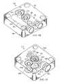
- FIGS. 4A and 4Bare diagrammatic representations of one embodiment of a low-profile filter 210 .
- Low-profile filter 210includes a filter housing 400 having a generally horizontal filter cavity 402 therein. Although only shown as originating from surface 404 , filter cavity 402 can originate from additional exterior surfaces of filter housing 400 to facilitate insertion of filter assembly 430 (discussed below).
- One or more portse.g., port 406 , port 408 , port 410 , port 412 ) on the top surface and bottom surface of filter housing 400 act as inlets or outlets to low-profile filter 210 .
- Flow passages defined in filter housing 400lead gas to/from filter cavity 402 and to/from the inlet/outlet ports.
- flow passage 414runs from bottom port 406 to filter cavity 402 while flow passage 416 runs from filter cavity 402 to top port 410 .
- Flow passage 418is a pass through passage running between bottom port 408 and top port 412 .
- Filter housing 400can further include various connector holes (one of which is indicated at 420 ) to allow filter housing 400 to be connected to a substrate block.
- Filter housing 400is formed of a material suitable for directing gas flow such as stainless steel, though other materials can be used.
- Various characteristics of filter housing 400can be configured to allow low-profile filter 210 to be compatible with a variety of substrate blocks and components.
- low-profile filter 210can be compatible with a C-Seal architecture. Consequently, filter housing 400 can be 1.125 inches wide, 1.125 inches deep (i.e., can have approximately the same footprint as a C-Seal substrate block) and 0.375 inches high.
- port 406will act as the inlet port to low-profile filter 210
- port 410will act as the outlet port to provide gas to a component stacked on top of low-profile filter 210 (i.e., according to the C-Seal architecture, the center port is the inlet port of a component)
- port 410will provide filtered gas to the stacked component
- port 408will be the outlet port to the substrate block.
- filter housing 400can provide the same port arrangement as a C-Seal substrate block.
- Filter housing 400is a unitary stainless steel block.
- Filter cavity 402 , ports 406 , 408 , 410 , and 412are machined into the stainless steel block using known machining techniques.
- Filter cavity 402for example, can have a diameter of 0.276 inches.
- the various flow passages and mounting holescan then be drilled. It should be noted that some semiconductor manufacturers specify that the hole in the center of a C-seal port leading to a flow passage can have a major diameter of no larger than 0.180 inches.
- the angle of the flow passage and diameter of flow passagecan be chosen such that the circle or ellipse (if drilled at an angle) at the entrance of the flow passage is no greater than a specified size (e.g., 0.180 inches). Assuming flow passage 416 is drilled at an angle to the top surface of housing 400 such that an elliptical inlet is formed, the angle and diameter of flow passage 416 running from filter cavity 402 to port 410 can be selected so that the major diameter of the inlet is no greater than 0.180 inches or other specified size.
- a specified sizee.g. 0.180 inches
- flow passage 414 from port 406 to filter cavity 402is machined in two stages.
- the first portionis machined from inlet port 406 into filter housing 400 .
- the angle and radius of flow passage 416can be selected such that the elliptical inlet to flow passage 416 does not exceed specified dimensions.
- the second portion of flow passage 416can be machined inward from the surface of filter cavity 402 at an angle to meet with the first section of flow passage 414 .
- the portion of flow channel 414 machined firstwill typically have a slightly larger diameter than the portion machined second, making it easier to ensure that the second portion cleanly meets the first portion during machining.
- the first portion of flow passage 414can have a diameter of 0.125 inches while the diameter of the second portion (the smaller portion) can be 0.094 inches.
- Flow passage 416can also have a diameter of approximately 0.125 inches, while flow passage 420 can have a diameter up to 0.180 inches in this example. It should be noted, however, any machining techniques can be used to form filter housing 400 .
- a filter assembly 430is disposed in filter cavity 402 and separates filter cavity 402 into two horizontally adjacent sections, shown generally at 432 and 434 (see, FIG. 5 ).
- Flow passage 414enters filter cavity 402 in section 432 and flow passage 416 enters filter cavity in section 434 .
- the flow passage from the inlet port 406 to the filter cavity 402i.e., flow passage 414
- the flow passage from filter cavity 402 to the outlet port 410are segregated by filter assembly 430 .
- filter assembly 430includes tube filter 438 coupled to adapter 440 .
- filter assembly 430can include any filter mechanism for segregating filter cavity 402 such that gas is filtered between the sections.
- Tube filter 438can include any tube filter suitable for a set of process requirements.
- tube filter 438can be a 0.003 micron stainless steel or nickel filter.
- steel and nickel tube filtersinclude Mykrolis Corp. Wafergard SL Gas Filters WGSLSFC1M and WGSLNFC1M respectively In these examples the wall thickness is about 0.020-0.065 inches with a pore size of 5-10 microns. (Mykrolis Corp. is based in Billerica, Mass.
- Adapter 440can be stainless steel or other material.
- Tube filter 438is welded or otherwise coupled to adapter 440 to form filter assembly 430 .
- the filter assemblyis inserted into filter cavity 402 and a seal formed between filter assembly 430 and the walls of filter cavity 402 .
- the sealis formed through an interference fit between adapter 440 and the wall of filter cavity 402 .
- the radius or outer dimension of adapter 440is slightly larger than the radius or outer dimension of filter cavity 402 at the area where adapter 440 will seal with the wall of filter cavity 402 .
- adapter 440can have a radius of be 0.0005-0.0015 inches greater than the radius of filter cavity 402 in the area that the seal is to be formed.
- Filter assembly 430can be forced into filter cavity 402 using a press to form the interference seal between adapter 440 and filter cavity 402 .
- filter assembly 430can be chilled (e.g., with liquid Nitrogen or other chilling method) and filter housing 400 heated. While filter assembly 430 is contracted due to cooling and filter cavity 402 dilated due to heating, filter assembly 430 is placed in filter cavity 402 . As filter assembly 430 and filter housing 400 reach ambient temperature, an interference seal will form between filter adapter 440 and the walls of filter cavity 402 .
- the filter assembly 430can be welded to the filter cavity 402 using e-beam, laser, tig or plasma.
- Filter cavity 402can be sealed at surface 404 using a sealing button, plug or other piece of material 424 (shown in FIG. 4B and FIG. 5 ).
- the sealing buttoncan be formed of stainless steel or other material that is preferably non-reactive or minimally reactive with the intended process gas. According to one embodiment, sealing button is sealed to filter housing 400 using a fusion weld.
- low-profile filter 210is mounted to a substrate, as shown in FIG. 2 .
- Gasenters flow passage 414 through port 406 and flows to section 432 of filter cavity 402 .
- the gasthen flows through the center of adapter 440 into tube filter 438 and permeates through the wall of tube filter 438 into section 434 of filter cavity 402 .
- the filtered gasflows from filter cavity 402 to port 410 via flow passage 416 to a component mounted on low-profile filter 210 .
- flow passage 414can enter filter cavity 402 in section 434 and flow passage 416 can enter filter cavity 402 in section 432 . Consequently, gas will be filtered by passing from the outside of tube filter 438 to the inside of tube filter 438 .
- FIG. 5is a diagrammatic representation of a cutaway view of low-profile filter 210 showing filter cavity 402 from the side. Shown in FIG. 5 is filter housing 400 including bottom port 406 , top ports 410 and 412 and filter cavity 402 . FIG. 5 also illustrates filter assembly 430 including tube filter 438 and adapter 440 . Sealing button 424 is also shown. As can be seen in FIG. 5 , filter assembly 430 separates filter cavity 402 into horizontally adjacent section 432 and section 434 . Flow passage 414 runs from bottom port 406 to filter cavity 402 while flow passage 416 runs from port 410 to filter cavity 402 . In this example, gas flows from a substrate block into port 406 and enters filter cavity 402 via flow passage 414 in section 432 .
- the gasflows through the center of adapter 440 into the center of tube filter 438 and permeates out of tube filter 438 into section 434 .
- the gasthen flows out of filter cavity 402 through flow passage 416 and through port 410 to a component mounted on low-profile filter 210 .
- the gasreturns from the component through port 412 and is lead back to the substrate block. In this example, the gas is filtered prior to entering the component.
- FIG. 6is a diagrammatic representation of a cutaway view of low-profile filter 210 of FIG. 4A .
- FIG. 6illustrates filter housing 400 , port 406 , port 408 , port 410 , port 412 , flow passage 416 , flow passage 418 and tube filter 438 .
- flow passage 416directs gas filtered by tube filter 438 to a component mounted on low-profile filter 210 . Gas returning from the component enters filter housing 400 at port 412 .
- Flow passage 418is a pass-through flow passage that leads the gas from port 412 to port 408 and the underlying substrate block.
- low-profile filter 210filters gas prior to providing the gas to the component mounted on low-profile filter 210 . In other embodiments, however, low-profile filter 210 can filter the gas after has been output by the component back to low-profile filter 210 .
- FIG. 7is a diagrammatic representation of a low-profile filter 210 for filtering gas on the outlet side of the component.
- low-profile filter 210includes a filter housing 700 having a generally horizontal filter cavity 702 therein. Although only shown as originating from surface 704 , filter cavity 702 can originate from additional exterior surfaces of filter housing 700 to facilitate insertion of filter assembly 730 (discussed below).
- One or more portson the top surface and bottom surface of filter housing 700 act as inlets or outlets to low-profile filter 210 .
- Flow passages defined in filter housing 700lead gas to/from filter cavity 702 and to/from the inlet/outlet ports.
- flow passage 714runs from bottom port 706 to top port 710 .
- Flow passage 716runs from top port 712 to filter cavity 702 while flow passage 718 (shown in FIG. 8 ) runs from filter cavity 702 to bottom port 708 .
- Filter housing 700can further include various connector holes (indicated at 720 ) to allow filter housing 700 to be connected to a substrate block.
- Filter housing 700can be formed of a unitary block of material and can be dimensioned and machined in a manner similar to that described in conjunction with filter housing 400 of FIGS. 4A and 4B but with the flow passages arranged to provide outlet side filtering.
- a filter assembly 730is disposed in filter cavity 702 and separates filter cavity 702 into two horizontally adjacent sections, shown generally at 732 and 734 (shown in FIG. 8 ).
- Flow passage 716enters filter cavity 702 in section 732 and flow passage 718 enters filter cavity in section 734 .
- the flow passage from the top inlet port 712 to the filter cavity 702i.e., flow passage 716
- the flow passage from filter cavity 702 to the bottom outlet port 708i.e., flow passage 718
- filter assembly 730includes tube filter 738 coupled to adapter 740 (better seen in FIG. 8 ).
- filter assembly 730can include any filter mechanism for segregating filter cavity 702 such that gas is filtered between the sections.
- Tube filter 738can include any tube filter suitable for a set of process requirements.
- tube filter 738can be a 0.003 micron stainless steel or nickel filter.
- Adapter 740can be stainless steel or other material.
- Filter assembly 730can be formed in a similar manner as filter assembly 430 of FIG. 4A and can be coupled to filter housing 700 to form an interference seal or other seal.
- Filter cavity 702can be sealed at surface 704 using a sealing button 724 (shown in FIG. 8 ) or other piece of material.
- Button 724can be formed of stainless steel or other material that is preferably non-reactive or minimally reactive with the intended process gas. According to one embodiment, button 724 is sealed to filter housing 700 using a fusion weld.
- low-profile filter 210is mounted to a substrate, as shown in FIG. 2 .
- Gasenters flow passage 714 through port 706 and flows to the component mounted on top of low-profile filter 210 via port 710 .
- the componentreturns the gas to low-profile filter 210 via port 712 .
- the gasflows through flow passage 716 to filter cavity 702 .
- the gasthen flows through the center of adapter 740 into tube filter 738 and permeates through the wall of tube filter 738 into section 734 of filter cavity 702 .
- the filtered gasflows from filter cavity 702 to port 708 via flow passage 718 back to the substrate upon which low-profile filter 210 is mounted.
- flow passage 716can enter filter cavity 702 in section 734 and flow passage 718 can enter filter cavity 702 in section 732 . Consequently, gas will be filtered by passing from the outside of tube filter 738 to the inside of tube filter 738 . Regardless, filtering gas on the outlet side of the mounted component provides the advantage that any contaminants introduced by the component are filtered before the gas is routed to other components.
- FIG. 8is a diagrammatic representation of a cutaway view of low-profile filter 210 of FIG. 7 .
- filter housing 700including bottom ports 706 and 708 , top ports 710 and 712 and filter cavity 702 .
- filter assembly 730including tube filter 738 and adapter 740 .
- FIG. 8further illustrates sealing button 724 .
- filter assembly 730separates filter cavity 702 into horizontally adjacent section 732 and section 724 .
- Flow passage 716runs from top port 712 to filter cavity 702 while flow passage 718 runs from filter cavity 702 to bottom port 708 .
- gasflows from a substrate block into port 706 and through to port 710 .
- the gasflows from port 712 to filter cavity 702 , through the center of adapter 740 into the center of tube filter 738 and permeates out of tube filter 738 into section 734 .
- the gasthen flows out of low-profile filter 210 through port 708 to the substrate block.
- the orientation of flow passagescan be reversed such that gas is filtered by passing gas from the outside of tube filter 738 to the center of tube filter 738 .
- FIGS. 9A and 9Bare diagrammatic representations of one embodiment of a dual filter configuration low-profile filter 210 .
- low-profile filter 210includes a filter housing 900 having a pair of generally horizontal filter cavities 902 and 903 therein. Although only shown as originating from surface 904 , filter cavities 902 and 904 can originate from additional exterior surfaces of filter housing 900 to facilitate insertion of filter assemblies 930 and 931 .
- One or more ports on the top surface and bottom surface of filter housing 900act as inlets or outlets to low-profile filter 210 . From the perspective of FIGS.
- Flow passages defined in filter housing 900lead gas to/from the filter cavities 902 and 903 and to/from the inlet/outlet ports.
- flow passage 914runs from a bottom port to filter cavity 902 and filter cavity 903 .
- a flow passageleads from filter cavity 902 to port 910 while another flow passage runs from filter cavity 903 to port 910 .
- the flow passage from port 912 to the bottom outlet portacts as a pass through passage.
- a filter assembly 930is disposed in filter cavity 902 and a second filter assembly 931 is disposed in filter cavity 903 .
- Filter assembly 930separates filter cavity 902 into two horizontally adjacent sections, while filter assembly 931 separates filter cavity 903 into two horizontally sections.
- Flow passage 914enters filter cavity 902 in the first section of filter cavity 902 and filter cavity 903 in the first section of filter cavity 903 .
- the outlet flow passage(e.g., running from filter cavity 902 to port 910 ) enters filter cavity 902 in the second section of filter cavity 902 while the outlet flow passage of filter cavity 903 (e.g., running from filter cavity 903 to port 910 ) enters filter cavity 903 in the second section of filter cavity 903 .
- flow passage 914is separated from the outlet of filter cavity 902 by filter assembly 930 and the outlet of filter cavity 903 by filter assembly 931 .
- filter assembly 930 and filter assembly 931can be similar to the previously described filter assemblies and can include an adapter and tube filter.
- either filter assemblycan include any filter mechanism for segregating the respective filter cavity into sections such that gas is filtered between the sections.
- the tube filterscan be a 0.003 micron stainless steel or nickel filter while the adapters can be stainless steel or other material.
- Filter assemblies 930 and 931can be formed in a similar manner as filter assembly 430 of FIG. 4A and FIG. 4B and can be coupled to filter housing 900 to form an interference seal or other seal.
- Filter cavity 902 and filter cavity 903can be sealed at surface 904 using a sealing button or plug formed of stainless steel or other material that is preferably non-reactive or minimally reactive with the intended process gas.
- the plugs or sealing buttonscan be sealed to filter housing 900 using a fusion weld.
- low-profile filter 210is mounted to a substrate, as shown in FIG. 2 .
- Gasenters flow passage 914 through a bottom port and flows to filter cavity 902 and 903 .
- the gasflows through the center of filter assemblies 930 and 931 and permeates into the other sections of filter cavity 902 and 903 , respectively. Again, however, this flow can be reversed such that the gas is filtered by flowing into, rather than out of, the tube filters.
- Flow passagesdirect gas to port 910 from filter cavity 902 and filter cavity 903 .
- Gasreturns from component through port 912 , through a pass through flow passage and out an outlet port on the bottom of filter housing 900 .
- the flow pathis similar to that described in conjunction with FIGS. 4A , 4 B and 5 except that the gas is directed to two filter cavities in parallel to filter the gas before the gas is directed to the component stacked on top of low-profile filter 210 .
- low-profile filter 210acts as an inlet filter.
- low-profile filter 210can be configured as a dual filter for the outlet side of a component.
- one filtercan act on the inlet side of the component while the other filter can act on the outlet side of the component.
- both filtercan be in the same filter cavity (e.g., inserted from each end) and the gas recirculated through the filter cavity.
- dual filtersprovides an advantage over a single filter because the dual filters can provide for greater surface area using a small diameter. This can allow for a greater or similar pressure drop to a single filter, while allowing the height of filter housing 900 to be reduced. Additionally, multiple smaller diameter filters can be used for filter housings in which the port placement does not allow a larger filter to fit.
- FIG. 10is a diagrammatic representation of yet another embodiment of low-profile filter 210 .
- Low-profile filter 210includes a filter housing 1000 having a generally horizontal filter cavity 1002 therein. Although only shown as originating from one surface, filter cavity 1002 can originate from additional exterior surfaces of filter housing 1000 to facilitate insertion of filter assembly 1030 .
- One or more portse.g., port 1006 , port 1008 , port 1010 , port 1012 ) on the top surface and bottom surface of filter housing 1000 act as inlets or outlets to low-profile filter 210 .
- Flow passages defined in filter housing 1000lead gas to/from filter cavity 1002 and to/from the inlet/outlet ports.
- flow passage 1014runs from bottom port 1006 to filter cavity 1002 while flow passage 1016 runs from filter cavity 1002 to top port 1010 .
- Flow passage 1018is a pass through passage running between bottom port 1008 and top port 1012 .
- Filter housing 1000can further include various connector holes to allow filter housing 1000 to be connected to a substrate block.
- a filter assembly 1030is disposed in filter cavity 1002 and separates filter cavity 1002 into two horizontally adjacent sections.
- Flow passage 1014enters filter cavity 1002 in the first section and flow passage 1016 enters filter cavity in the second section.
- the flow passage from the inlet port 1006 to the filter cavity 1002i.e., flow passage 1014
- the flow passage from filter cavity 1002 to the outlet port 1010are segregated by filter assembly 1030 .
- filter assembly 1030includes tube filter 1038 coupled to adapter 1040 .
- filter assembly 1030can include any filter mechanism for segregating filter cavity 1002 such that gas is filtered between the sections.
- Tube filter 1038can include any tube filter suitable for a set of process requirements.
- Tube filter 1038is a TEFLON filter comprising multiple TEFLON tubes (e.g., hollow fibers) that are open to the first section.
- the tubescan optionally be straight tubes or, for example, “U” shaped tubes.
- Adapter 1040can be a stainless steel ring. Examples of similar TEFLON tubes can be found in Mykrolis Corp. pHasor Membrane Contactor PH2005F0F.
- the TEFLON tubeshave a pore size of approximately 5 microns and a wall thickness of 0.006-0.012 inches, though the pore size, tube length and wall thickness can be controlled during the process of making the tubes.
- a layer of TEFLONseals the gaps between the TEFLON tubes and between the TEFLON tubes and adapter 1040 .
- One embodiment for forming filter assembly 1030is described in greater detail in conjunction with FIG. 11 .
- Filter assembly 1030is inserted into filter cavity 1002 and a seal formed between filter assembly 1030 and the walls of filter cavity 1002 .
- the sealis formed through an interference fit between adapter 1040 and the wall of filter cavity 1002 .
- the radius or outer dimension of adapter 1040is slightly larger than the radius or outer dimension of filter cavity 1002 at the area where adapter 1040 will seal with the wall of filter cavity 1002 .
- adapter 1040can have a diameter of be 0.001 to 0.002 inches greater than the diameter of filter cavity 1002 in the area that the seal is to be formed.
- Filter assembly 1030can be forced into filter cavity 1002 using a press to form the interference seal between adapter 1040 and filter cavity 1002 .
- filter assembly 1030can be chilled (e.g., with liquid Nitrogen or other chilling method) and filter housing 1000 heated. While filter assembly 1030 is contracted due to cooling and filter cavity 1002 dilated due to heating, filter assembly 1030 is placed in filter cavity 1002 . As filter assembly 1030 and filter housing 1000 reach ambient temperature, an interference seal will form between filter adapter 1040 and the walls of filter cavity 1002 .
- Filter cavity 1002can be sealed at the surface of housing 1000 using a sealing button 1024 or other piece of material.
- Button 1024can be formed of stainless steel or other material that is preferably non-reactive or minimally reactive with the intended process gas. According to one embodiment, button 1024 is sealed to filter housing 1000 using a fusion weld.
- low-profile filter 210is mounted to a substrate, as shown in FIG. 2 .
- Gasenters flow passage 1014 through port 1006 and flows into the first section of filter cavity 1002 .
- the gasthen flows through the open ends of the TEFLON tubes exposed to the first section of filter cavity 1002 and permeates through the walls of the tubes into the other section of filter cavity 1002 .
- the filtered gasflows from filter cavity 1002 to port 1010 via flow passage 1016 to a component mounted on low-profile filter 210 .
- the flow passagescan be arranged such that gas will be filtered by passing from the outside of tube filter 1038 to the inside of the TEFLON tubes.
- gasis filtered on the inlet side of component mounted to low-profile filter 210 .
- gascan be filtered on the outlet side of the component or both the inlet and outlet side.
- multiple TEFLON (or other material) filterscan be used to filter can on the inlet side, outlet side or both.
- FIG. 11illustrates one embodiment of forming filter assembly 1030 .
- Adapter 1040 and multiple TEFLON tubese.g., such as tube 1102
- a crucible 1103Small TEFLON beads are interspersed between the tubes (e.g., beads 1104 ) to act as a potting material.
- beads 1104have a lower melting temperature than the TEFLON tubes and adapter 1040 .
- TEFLON tubescan be PFA TEFLON while the TEFLON beads can be MFA TEFLON.
- the crucibleis heated to a temperature that melts beads 1104 , but not the TEFLON tubes or adapter 1040 .
- the cruciblecan be cooled to ambient temperature to allow the melted TEFLON to cool into TEFLON seal 1106 .
- the end of the TEFLON tubescan then be cut off to ensure that the tubes are not plugged by the TEFLON seal 1106 .
- the tubescan be made flush with adapter 1040 .
- TEFLON seal 1106may not bond completely with adapter 1040 (e.g., due to the respective material properties of the TEFLON and adapter), a mechanical seal between the TEFLON seal 1106 and adapter 1040 can be completed when adapter 1040 is deformed through establishing the interference fit with filter housing 1000 (i.e., when the adapter is “squeezed” by the filter cavity walls to form an interference fit).
- low-profile filterhas been described in the context of a filter that is located between a substrate block and a component. According to other embodiments of the present invention, however, low-profile filter can be a standalone filter (e.g., low-profile filter 310 of FIG. 3 ).
- FIG. 12is a diagrammatic representation of one embodiment of a cutaway view of low-profile filter 310 .
- Low-profile filter 310includes a filter housing 1200 having a generally horizontal filter cavity 1202 therein. Although only shown as originating from one surface, filter cavity 1202 can originate from additional exterior surfaces of filter housing 1200 to facilitate insertion of filter assembly 1230 .
- One or more portson the bottom surface of filter housing 1200 act as inlets or outlets to low-profile filter 310 .
- Flow passages defined in filter housing 1200lead gas to/from filter cavity 1202 and to/from the inlet/outlet ports.
- flow passage 1214runs from bottom port 1206 to filter cavity 1202 while flow passage 1216 runs from filter cavity 1202 to bottom port 1208 .
- Filter housing 1200can further include various connector holes (indicated at 1220 ) to allow filter housing 1200 to be connected to a substrate block.
- Filter housing 1200is formed of a material suitable for directing gas flow such as stainless steel, though other materials can be used. Various characteristics of filter housing 1200 can be configured to allow low-profile filter 310 to be compatible with a variety of substrate blocks and components. By way of example, but not limitation, low-profile filter 310 can be compatible with a C-Seal architecture.
- a filter assembly 1230is disposed in filter cavity 1202 and separates filter cavity 1202 into two horizontally adjacent sections, shown generally at 1232 and 1234 .
- Flow passage 1214enters filter cavity 1202 in section 1232 and flow passage 1216 enters filter cavity in section 1234 .
- Filter assembly 1230can include a filter assembly similar to filter assemblies 430 , 730 , 930 , 931 , 1030 or other filter assemblies
- Filter cavity 1202can be sealed with a button 1224 or by other mechanism as discussed above.
- low-profile filter 310is mounted to a substrate, as shown in FIG. 3 .
- Gasenters flow passage 1214 through port 1206 and flows to section 1232 of filter cavity 1202 .
- the gasthen flows through the center of adapter 1240 into tube filter 1238 and permeates through the wall of tube filter 1238 into section 1234 of filter cavity 1202 .
- the filtered gasflows from filter cavity 1202 to port 1208 via flow passage 1216 back to the substrate block.
- flow passage 1214can enter filter cavity 1202 in section 1234 and flow passage 1216 can enter filter cavity 1202 in section 1232 . Consequently, gas will be filtered by passing from the outside of tube filter 1238 to the inside of tube filter 1238 .
- filter 310can include multiple filter cavities for filtering the gas in parallel or series.
- FIG. 13is a diagrammatic representation of another embodiment of the present invention.
- low-profile filter 210includes a filter housing 1300 having a generally horizontal filter cavity 1302 therein. Although only shown as being open to one surface, filter cavity 1302 can be open to additional exterior surfaces of filter housing 1300 .
- Various ports and flow passages(not shown) can be arranged in a manner similar to those previously described or in other suitable arrangements.
- a filter assembly 1330is disposed in filter cavity 1302 and separates filter cavity 1302 into three horizontally spaced sections, shown generally at 1332 , 1334 and 1335 .
- the inlet to filter cavity 1302enters in section 1332 and the outlet exits at section 1335 .
- Gasenters filter cavity 1302 , flows through filter assembly 1330 and exits filter cavity 1302 .
- filter assembly 1330includes one or more disk filters (e.g., disk filters 1342 , 1344 ) across filter cavity 1302 such that gas flows through the disk filters in a primarily horizontal direction.
- Each disk filtercan include any filter suitable for a set of process requirements, including by way of example but not limitation, steel, ceramic, nickel or other disk filters.
- Adapter 1340is welded or otherwise coupled to the disk filters to form a seal. As described above, adapter 1340 can be sealed to housing 1300 using an interference fit or other seal. While, in the example above, a single adapter seats multiple disks, in other embodiments, multiple adapters can be used.
- Filter cavity 1302can be sealed using a sealing button 1324 or other piece of material.
- Button 1324can be formed of stainless steel or other material that is preferably non-reactive or minimally reactive with the intended process gas. According to one embodiment, button 1324 is sealed to filter housing 1300 using a fusion weld.
- embodiments of the present inventioncan provide low-profile filters that uses one or more disk filters to filter a gas.
- FIG. 14is a diagrammatic representation of an other example of a mechanical seal that can be used.
- a metal or other material gasket 1402e.g., a steel ring or other gasket
- Each of filter housing 1406 and adapter 1404can include a thin protruding edge (e.g., edge 1408 and edge 1410 ). When adapter 1404 is pressed into the filter cavity, the respective edges dig into gasket 1402 , creating a mechanical seal.
- Embodiments of the present inventionthus provide low-profile filters that can fit between components of a gas stick or act as a standalone filter with minimal impact on overall gas stick height.
- the low-profile filterscan filter on the inlet side, outlet side or both sides of a component mounted thereon. While specific examples of dimensions and filters have been used, these examples are for the purposes of illustration. Other suitable dimensions and materials can be used. Moreover, any suitable filter, such as a pleated filter can be used.
- Various embodiments of the present inventionprovide advantages over prior art filters by reducing the number of components required and reducing the number of seals per filter required. This reduces the number of seals that potentially interrupt the gas flow path, minimal internal wetted surface are, minimal internal dead space, reduced likelihood of leakage and reduced filter height.
Landscapes
- Chemical & Material Sciences (AREA)
- Chemical Kinetics & Catalysis (AREA)
- Engineering & Computer Science (AREA)
- Analytical Chemistry (AREA)
- General Chemical & Material Sciences (AREA)
- Oil, Petroleum & Natural Gas (AREA)
- Filtering Of Dispersed Particles In Gases (AREA)
- Separation Using Semi-Permeable Membranes (AREA)
- Control Of Motors That Do Not Use Commutators (AREA)
- Filtering Materials (AREA)
Abstract
Description
Claims (26)
Priority Applications (9)
| Application Number | Priority Date | Filing Date | Title |
|---|---|---|---|
| US11/353,294US7575616B2 (en) | 2006-02-10 | 2006-02-10 | Low-profile surface mount filter |
| TW96104638ATWI439313B (en) | 2006-02-10 | 2007-02-08 | Low surface mount filter |
| JP2008554409AJP5328372B2 (en) | 2006-02-10 | 2007-02-09 | Thin surface mount filter |
| KR1020087016018AKR101357415B1 (en) | 2006-02-10 | 2007-02-09 | Low-profile surface mount filter |
| EP07750463.7AEP1989036B1 (en) | 2006-02-10 | 2007-02-09 | Low-profile surface mount filter |
| CN2007800024930ACN101370639B (en) | 2006-02-10 | 2007-02-09 | Low-profile surface mount filter |
| PCT/US2007/003628WO2007095145A2 (en) | 2006-02-10 | 2007-02-09 | Low-profile surface mount filter |
| US12/509,970US7806949B2 (en) | 2006-02-10 | 2009-07-27 | Low-profile surface mount filter |
| US12/897,540US7967882B2 (en) | 2006-02-10 | 2010-10-04 | Low-profile surface mount filter |
Applications Claiming Priority (1)
| Application Number | Priority Date | Filing Date | Title |
|---|---|---|---|
| US11/353,294US7575616B2 (en) | 2006-02-10 | 2006-02-10 | Low-profile surface mount filter |
Related Child Applications (1)
| Application Number | Title | Priority Date | Filing Date |
|---|---|---|---|
| US12/509,970DivisionUS7806949B2 (en) | 2006-02-10 | 2009-07-27 | Low-profile surface mount filter |
Publications (2)
| Publication Number | Publication Date |
|---|---|
| US20070186775A1 US20070186775A1 (en) | 2007-08-16 |
| US7575616B2true US7575616B2 (en) | 2009-08-18 |
Family
ID=38366987
Family Applications (3)
| Application Number | Title | Priority Date | Filing Date |
|---|---|---|---|
| US11/353,294Active2027-06-02US7575616B2 (en) | 2006-02-10 | 2006-02-10 | Low-profile surface mount filter |
| US12/509,970ActiveUS7806949B2 (en) | 2006-02-10 | 2009-07-27 | Low-profile surface mount filter |
| US12/897,540ActiveUS7967882B2 (en) | 2006-02-10 | 2010-10-04 | Low-profile surface mount filter |
Family Applications After (2)
| Application Number | Title | Priority Date | Filing Date |
|---|---|---|---|
| US12/509,970ActiveUS7806949B2 (en) | 2006-02-10 | 2009-07-27 | Low-profile surface mount filter |
| US12/897,540ActiveUS7967882B2 (en) | 2006-02-10 | 2010-10-04 | Low-profile surface mount filter |
Country Status (7)
| Country | Link |
|---|---|
| US (3) | US7575616B2 (en) |
| EP (1) | EP1989036B1 (en) |
| JP (1) | JP5328372B2 (en) |
| KR (1) | KR101357415B1 (en) |
| CN (1) | CN101370639B (en) |
| TW (1) | TWI439313B (en) |
| WO (1) | WO2007095145A2 (en) |
Cited By (5)
| Publication number | Priority date | Publication date | Assignee | Title |
|---|---|---|---|---|
| US20110078886A1 (en)* | 2006-02-10 | 2011-04-07 | Diprizio Anthony | Low-profile surface mount filter |
| US20130056087A1 (en)* | 2007-10-12 | 2013-03-07 | Lam Research Corporation | Universal fluid flow adaptor |
| US9147188B2 (en) | 2010-10-26 | 2015-09-29 | Tectonics | Electronic currency and authentication system and method |
| WO2017176622A2 (en) | 2016-04-07 | 2017-10-12 | Entegris, Inc. | Gas filter |
| US20220199431A1 (en)* | 2019-04-15 | 2022-06-23 | Lam Research Corporation | Modular-component system for gas delivery |
Families Citing this family (7)
| Publication number | Priority date | Publication date | Assignee | Title |
|---|---|---|---|---|
| US20110041470A1 (en)* | 2006-08-25 | 2011-02-24 | Pall Corporation | Fluid assemblies comprising a purification element |
| US7806143B2 (en)* | 2007-06-11 | 2010-10-05 | Lam Research Corporation | Flexible manifold for integrated gas system gas panels |
| US8950433B2 (en)* | 2011-05-02 | 2015-02-10 | Advantage Group International Inc. | Manifold system for gas and fluid delivery |
| ES2561900T3 (en)* | 2012-12-10 | 2016-03-01 | Gometrics S.L. | Gas mixer |
| CN103192516B (en)* | 2013-04-02 | 2015-02-25 | 上海正乾生物技术有限公司 | High-pressure extruding and filtering system for preparing liposome |
| US10363503B1 (en) | 2018-10-19 | 2019-07-30 | Marvin Salganov | Foldable multi-stage water filter system |
| KR102602359B1 (en)* | 2018-11-22 | 2023-11-16 | 에이치엘만도 주식회사 | Check valve and moudulator block including it |
Citations (81)
| Publication number | Priority date | Publication date | Assignee | Title |
|---|---|---|---|---|
| US2528557A (en) | 1944-10-27 | 1950-11-07 | Samuel A Shapiro | Refrigerant control manifold |
| US3516436A (en) | 1967-03-14 | 1970-06-23 | Inst Werkzeugmaschinen | Arrangement for interconnecting logical operational units for pneumatic controls |
| US3589387A (en) | 1969-08-22 | 1971-06-29 | Int Basic Economy Corp | Integrated manifold circuits and method of assembly |
| US3654960A (en) | 1969-12-31 | 1972-04-11 | Hydro Stack Mfg Corp | Modular hydraulic system |
| US3834417A (en) | 1972-04-10 | 1974-09-10 | Norgren Co C A | Coupling unit for fluid control components |
| US4384474A (en) | 1980-10-30 | 1983-05-24 | Amf Incorporated | Method and apparatus for testing and using membrane filters in an on site of use housing |
| US4784880A (en)* | 1986-07-25 | 1988-11-15 | Albany International Corp. | Method for modifying asymmetric membranes by endo-treating |
| US5163475A (en) | 1991-11-26 | 1992-11-17 | Praxair Technology, Inc. | Gas delivery panels |
| US5303731A (en) | 1992-06-30 | 1994-04-19 | Unit Instruments, Inc. | Liquid flow controller |
| US5333637A (en) | 1993-06-11 | 1994-08-02 | Rosemount Inc. | Pneumatic instrument particle trap |
| US5423228A (en) | 1992-12-18 | 1995-06-13 | Monitor Labs, Inc. | Dilution stack sampling apparatus |
| US5468384A (en) | 1992-10-20 | 1995-11-21 | Societe Anonyme Dite Societe Des Ceramiques Techniques | Module for filtering, separating, purifying gases or liquids, or for catalytic conversion |
| US5490397A (en) | 1991-04-15 | 1996-02-13 | Nippondenso Co., Ltd. | Water removing device in refrigerating system |
| WO1996034705A1 (en) | 1995-05-05 | 1996-11-07 | Insync Systems, Inc. | Mfc-quick change method and apparatus |
| US5605179A (en) | 1995-03-17 | 1997-02-25 | Insync Systems, Inc. | Integrated gas panel |
| US5617898A (en) | 1991-09-10 | 1997-04-08 | Smc Kabushiki Kaisha | Fluid pressure apparatus |
| EP0791670A2 (en) | 1996-02-21 | 1997-08-27 | Aeroquip Corporation | Ultra high purity gas distribution component with integral valved coupling and methods for its use |
| US5684245A (en) | 1995-11-17 | 1997-11-04 | Mks Instruments, Inc. | Apparatus for mass flow measurement of a gas |
| US5730181A (en) | 1994-07-15 | 1998-03-24 | Unit Instruments, Inc. | Mass flow controller with vertical purifier |
| US5732744A (en)* | 1996-03-08 | 1998-03-31 | Control Systems, Inc. | Method and apparatus for aligning and supporting semiconductor process gas delivery and regulation components |
| US5769110A (en) | 1995-06-30 | 1998-06-23 | Fujikin Incorporated | Fluid control apparatus |
| US5819782A (en) | 1996-01-05 | 1998-10-13 | Ckd Corporation | Gas supply unit |
| US5836355A (en)* | 1996-12-03 | 1998-11-17 | Insync Systems, Inc. | Building blocks for integrated gas panel |
| US5908553A (en) | 1996-12-06 | 1999-06-01 | Reid; Roger P. | Water purifier with adjustable volume in dwell passage |
| US5964481A (en) | 1998-07-10 | 1999-10-12 | Buch; Dana | Modular mounting apparatus for fluid control components |
| US5992463A (en) | 1996-10-30 | 1999-11-30 | Unit Instruments, Inc. | Gas panel |
| US6012479A (en) | 1997-02-28 | 2000-01-11 | Benkan Corporation | Integrated gas control device |
| US6068016A (en)* | 1997-09-25 | 2000-05-30 | Applied Materials, Inc | Modular fluid flow system with integrated pump-purge |
| US6078030A (en)* | 1998-09-09 | 2000-06-20 | Millipore Corporation | Component heater for use in semiconductor manufacturing equipment |
| US6123107A (en) | 1999-07-09 | 2000-09-26 | Redwood Microsystems, Inc. | Apparatus and method for mounting micromechanical fluid control components |
| US6123340A (en) | 1998-01-09 | 2000-09-26 | Swagelok Company | Modular flow devices |
| US6149718A (en) | 1998-10-16 | 2000-11-21 | Mott Mettallurgical Corporation | Contamination control system |
| US6155289A (en)* | 1999-05-07 | 2000-12-05 | International Business Machines | Method of and system for sub-atmospheric gas delivery with backflow control |
| US6158454A (en)* | 1998-04-14 | 2000-12-12 | Insync Systems, Inc. | Sieve like structure for fluid flow through structural arrangement |
| US6186177B1 (en)* | 1999-06-23 | 2001-02-13 | Mks Instruments, Inc. | Integrated gas delivery system |
| US6227248B1 (en)* | 1997-12-11 | 2001-05-08 | Smc Corporation | Manifold-type flow detector assembly |
| US6234455B1 (en)* | 1994-06-30 | 2001-05-22 | Gotz-Ulrich Wittek | Device and process for delivering substances for dispersal in the air |
| US20010003287A1 (en)* | 1997-02-14 | 2001-06-14 | Armstrong, Westerman, Hattori, Mcleland & Naughton | Fluid control apparatus |
| US6260581B1 (en)* | 1998-06-12 | 2001-07-17 | J. Gregory Hollingshead | Apparatus for assembling modular chemical distribution substrate blocks |
| US6273139B1 (en)* | 1997-10-13 | 2001-08-14 | Fujikin, Inc. | Fluid control apparatus |
| US6283155B1 (en)* | 1999-12-06 | 2001-09-04 | Insync Systems, Inc. | System of modular substrates for enabling the distribution of process fluids through removable components |
| US6293310B1 (en)* | 1996-10-30 | 2001-09-25 | Unit Instruments, Inc. | Gas panel |
| US6298881B1 (en)* | 1999-03-16 | 2001-10-09 | Shigemoto & Annett Ii, Inc. | Modular fluid handling assembly and modular fluid handling units with double containment |
| US20020011113A1 (en)* | 1998-11-20 | 2002-01-31 | Tsourides Christ A. | System and method for integrating gas components |
| US20020017329A1 (en)* | 2000-08-01 | 2002-02-14 | Benkan Corporation | Integrated gas control device |
| US6349744B1 (en)* | 2000-10-13 | 2002-02-26 | Mks Instruments, Inc. | Manifold for modular gas box system |
| US20020033195A1 (en)* | 2000-09-11 | 2002-03-21 | Hideki Fujimoto | Fluid control apparatus and gas treatment system comprising same |
| US20020050299A1 (en)* | 1999-09-01 | 2002-05-02 | Nhan Nguyen | Modular fluid delivery apparatus |
| US6382238B2 (en)* | 2000-03-10 | 2002-05-07 | Tokyo Electron Limited | Fluid control apparatus |
| US6394138B1 (en)* | 1996-10-30 | 2002-05-28 | Unit Instruments, Inc. | Manifold system of removable components for distribution of fluids |
| US20020117221A1 (en)* | 2000-12-06 | 2002-08-29 | Osamu Uchizawa | Integration unit |
| US20020185185A1 (en)* | 2001-05-23 | 2002-12-12 | Michio Yamaji | Fluid control apparatus |
| US20020195165A1 (en)* | 2001-05-16 | 2002-12-26 | Vu Kim Ngoc | Fluid flow system |
| US6514323B1 (en) | 1998-06-24 | 2003-02-04 | Pall Corporation | Purification assemblies and purification methods |
| US6546960B1 (en)* | 2000-03-03 | 2003-04-15 | Creative Pathways, Inc. | Self-aligning SmartStrate™ |
| US20030106597A1 (en)* | 2001-12-06 | 2003-06-12 | Ckd Corporation | Gas supply unit |
| US20030116207A1 (en)* | 2001-12-21 | 2003-06-26 | Ian Symington | Apparatus for conveying fluids and base plate |
| US20040129324A1 (en)* | 2002-08-27 | 2004-07-08 | Celerity Group, Inc. | Modular substrate gas panel having manifold connections in a common plane |
| US20040143404A1 (en)* | 2003-01-17 | 2004-07-22 | Applied Materials, Inc. | Method and apparatus for analyzing gas flow in a gas panel |
| US20040168732A1 (en)* | 2002-11-26 | 2004-09-02 | Perusek Robert V. | Modular surface mount fluid system |
| US20040173270A1 (en)* | 2003-03-03 | 2004-09-09 | Harris James M. | Fluid delivery system and mounting panel therefor |
| US20050005981A1 (en)* | 2003-03-26 | 2005-01-13 | Paul Eidsmore | Modular fluid components and assembly |
| US20050061377A1 (en)* | 1999-08-24 | 2005-03-24 | Hayashi Otsuki | Gas processing apparatus, gas processing method and integrated valve unit for gas processing apparatus |
| US20050072481A1 (en)* | 2001-12-06 | 2005-04-07 | Toshihiro Hanada | Manifold valve |
| US20050224121A1 (en)* | 2004-04-13 | 2005-10-13 | Milburn Matthew L | Gas-panel assembly |
| US20050229972A1 (en)* | 2001-03-05 | 2005-10-20 | George Hoshi | Fluid controller |
| US20050284529A1 (en)* | 2004-06-25 | 2005-12-29 | Toshiaki Iwabuchi | Integrated gas control device |
| US20050284528A1 (en)* | 2004-01-30 | 2005-12-29 | Applied Materials, Inc. | Methods and apparatus for providing fluid to a semiconductor device processing apparatus |
| US20060005891A1 (en)* | 2004-07-09 | 2006-01-12 | Michael Doyle | Modular fluid distribution system |
| US20060011246A1 (en)* | 2004-07-09 | 2006-01-19 | Leys John A | Fluid flow control system and method |
| US20060027274A1 (en)* | 2004-08-04 | 2006-02-09 | Funes Warner F | Fluid control apparatus |
| US20060027275A1 (en)* | 2001-07-13 | 2006-02-09 | Talon Innovations, Inc. | Shear-resistant modular fluidic blocks |
| US20060048830A1 (en)* | 2002-12-03 | 2006-03-09 | Ichiro Tokuda | Fluid control device |
| US20060060253A1 (en)* | 2002-10-21 | 2006-03-23 | Ckd Corporation | Integrated gas valve |
| US7017609B2 (en)* | 2002-09-20 | 2006-03-28 | Ckd Corporation | Gas supply unit |
| US20060185746A1 (en)* | 2004-02-20 | 2006-08-24 | Michael Doyle | Modular fluid distribution system |
| US20060272720A1 (en)* | 2005-06-02 | 2006-12-07 | Milburn Matthew L | Gas-panel assembly |
| US20060272721A1 (en)* | 2005-06-02 | 2006-12-07 | Milburn Matthew L | Gas-panel assembly |
| US7410519B1 (en)* | 2005-08-16 | 2008-08-12 | Ewald Dieter H | Sandwich filter block |
| US20080302434A1 (en)* | 2007-06-11 | 2008-12-11 | Lam Research Corporation | Flexible manifold for integrated gas system gas panels |
| US7484527B2 (en)* | 2003-07-14 | 2009-02-03 | Kuroda Pneumatics Limited | Switch valve device |
Family Cites Families (12)
| Publication number | Priority date | Publication date | Assignee | Title |
|---|---|---|---|---|
| US516475A (en)* | 1894-03-13 | Thomas corscaden | ||
| US5136475A (en)* | 1990-10-29 | 1992-08-04 | Mcdermott Kevin | Emergency light for marking of aircraft landing sites and other purposes |
| JP2731080B2 (en)* | 1991-05-31 | 1998-03-25 | 株式会社本山製作所 | Gas control device |
| KR0177533B1 (en)* | 1993-02-11 | 1999-03-20 | 길버트 피. 와이너 | Piping filter |
| JPH07236808A (en)* | 1994-03-01 | 1995-09-12 | Koganei Corp | Filter device for vacuum piping |
| US5545242A (en)* | 1994-07-19 | 1996-08-13 | Pall Corporation | In-line filter for tubing |
| JPH08254283A (en)* | 1995-03-17 | 1996-10-01 | Motoyama Seisakusho:Kk | Valve |
| JP2003280745A (en)* | 2002-03-25 | 2003-10-02 | Stec Inc | Mass flow controller |
| US6934138B2 (en)* | 2002-08-08 | 2005-08-23 | General Instrument Corporation | Method and device for bonding AC utilities and HFC access networks for surge mitigation |
| JP4116366B2 (en)* | 2002-08-21 | 2008-07-09 | 日本精線株式会社 | Filter assembly |
| US7320333B2 (en) | 2005-05-09 | 2008-01-22 | Elkhart Brass Manufacturing Company, Inc. | Compact field adjustable pressure reducing valve |
| US7575616B2 (en) | 2006-02-10 | 2009-08-18 | Entegris, Inc. | Low-profile surface mount filter |
- 2006
- 2006-02-10USUS11/353,294patent/US7575616B2/enactiveActive
- 2007
- 2007-02-08TWTW96104638Apatent/TWI439313B/enactive
- 2007-02-09EPEP07750463.7Apatent/EP1989036B1/enactiveActive
- 2007-02-09JPJP2008554409Apatent/JP5328372B2/enactiveActive
- 2007-02-09KRKR1020087016018Apatent/KR101357415B1/enactiveActive
- 2007-02-09CNCN2007800024930Apatent/CN101370639B/enactiveActive
- 2007-02-09WOPCT/US2007/003628patent/WO2007095145A2/enactiveApplication Filing
- 2009
- 2009-07-27USUS12/509,970patent/US7806949B2/enactiveActive
- 2010
- 2010-10-04USUS12/897,540patent/US7967882B2/enactiveActive
Patent Citations (106)
| Publication number | Priority date | Publication date | Assignee | Title |
|---|---|---|---|---|
| US2528557A (en) | 1944-10-27 | 1950-11-07 | Samuel A Shapiro | Refrigerant control manifold |
| US3516436A (en) | 1967-03-14 | 1970-06-23 | Inst Werkzeugmaschinen | Arrangement for interconnecting logical operational units for pneumatic controls |
| US3589387A (en) | 1969-08-22 | 1971-06-29 | Int Basic Economy Corp | Integrated manifold circuits and method of assembly |
| US3654960A (en) | 1969-12-31 | 1972-04-11 | Hydro Stack Mfg Corp | Modular hydraulic system |
| US3834417A (en) | 1972-04-10 | 1974-09-10 | Norgren Co C A | Coupling unit for fluid control components |
| US4384474A (en) | 1980-10-30 | 1983-05-24 | Amf Incorporated | Method and apparatus for testing and using membrane filters in an on site of use housing |
| US4784880A (en)* | 1986-07-25 | 1988-11-15 | Albany International Corp. | Method for modifying asymmetric membranes by endo-treating |
| US5490397A (en) | 1991-04-15 | 1996-02-13 | Nippondenso Co., Ltd. | Water removing device in refrigerating system |
| US5617898A (en) | 1991-09-10 | 1997-04-08 | Smc Kabushiki Kaisha | Fluid pressure apparatus |
| US5163475A (en) | 1991-11-26 | 1992-11-17 | Praxair Technology, Inc. | Gas delivery panels |
| US5303731A (en) | 1992-06-30 | 1994-04-19 | Unit Instruments, Inc. | Liquid flow controller |
| US5468384A (en) | 1992-10-20 | 1995-11-21 | Societe Anonyme Dite Societe Des Ceramiques Techniques | Module for filtering, separating, purifying gases or liquids, or for catalytic conversion |
| US5423228A (en) | 1992-12-18 | 1995-06-13 | Monitor Labs, Inc. | Dilution stack sampling apparatus |
| US5333637A (en) | 1993-06-11 | 1994-08-02 | Rosemount Inc. | Pneumatic instrument particle trap |
| US6234455B1 (en)* | 1994-06-30 | 2001-05-22 | Gotz-Ulrich Wittek | Device and process for delivering substances for dispersal in the air |
| US5730181A (en) | 1994-07-15 | 1998-03-24 | Unit Instruments, Inc. | Mass flow controller with vertical purifier |
| US5605179A (en) | 1995-03-17 | 1997-02-25 | Insync Systems, Inc. | Integrated gas panel |
| WO1996034705A1 (en) | 1995-05-05 | 1996-11-07 | Insync Systems, Inc. | Mfc-quick change method and apparatus |
| US5769110A (en) | 1995-06-30 | 1998-06-23 | Fujikin Incorporated | Fluid control apparatus |
| US5684245A (en) | 1995-11-17 | 1997-11-04 | Mks Instruments, Inc. | Apparatus for mass flow measurement of a gas |
| US5819782A (en) | 1996-01-05 | 1998-10-13 | Ckd Corporation | Gas supply unit |
| US5810031A (en)* | 1996-02-21 | 1998-09-22 | Aeroquip Corporation | Ultra high purity gas distribution component with integral valved coupling and methods for its use |
| EP0791670A2 (en) | 1996-02-21 | 1997-08-27 | Aeroquip Corporation | Ultra high purity gas distribution component with integral valved coupling and methods for its use |
| US6035609A (en)* | 1996-02-21 | 2000-03-14 | Aeroquip Corporation | Ultra high purity gas distribution component with integral valved coupling and methods for its use |
| US5732744A (en)* | 1996-03-08 | 1998-03-31 | Control Systems, Inc. | Method and apparatus for aligning and supporting semiconductor process gas delivery and regulation components |
| US20010013371A1 (en)* | 1996-10-30 | 2001-08-16 | Redemann Eric J. | Gas panel |
| US5992463A (en) | 1996-10-30 | 1999-11-30 | Unit Instruments, Inc. | Gas panel |
| US6293310B1 (en)* | 1996-10-30 | 2001-09-25 | Unit Instruments, Inc. | Gas panel |
| US6374859B1 (en)* | 1996-10-30 | 2002-04-23 | Unit Instruments, Inc. | Manifold system for enabling a distribution of fluids |
| US6394138B1 (en)* | 1996-10-30 | 2002-05-28 | Unit Instruments, Inc. | Manifold system of removable components for distribution of fluids |
| US6189570B1 (en) | 1996-10-30 | 2001-02-20 | Unit Instruments, Inc. | Gas panel |
| US5836355A (en)* | 1996-12-03 | 1998-11-17 | Insync Systems, Inc. | Building blocks for integrated gas panel |
| US5908553A (en) | 1996-12-06 | 1999-06-01 | Reid; Roger P. | Water purifier with adjustable volume in dwell passage |
| US20030041910A1 (en)* | 1997-02-14 | 2003-03-06 | Tadahiro Ohmi, Sendai-Shi, Japan And Fujikin Incorporated | Fluid control apparatus |
| US20010003287A1 (en)* | 1997-02-14 | 2001-06-14 | Armstrong, Westerman, Hattori, Mcleland & Naughton | Fluid control apparatus |
| US6012479A (en) | 1997-02-28 | 2000-01-11 | Benkan Corporation | Integrated gas control device |
| US6068016A (en)* | 1997-09-25 | 2000-05-30 | Applied Materials, Inc | Modular fluid flow system with integrated pump-purge |
| US6273139B1 (en)* | 1997-10-13 | 2001-08-14 | Fujikin, Inc. | Fluid control apparatus |
| US6227248B1 (en)* | 1997-12-11 | 2001-05-08 | Smc Corporation | Manifold-type flow detector assembly |
| US6123340A (en) | 1998-01-09 | 2000-09-26 | Swagelok Company | Modular flow devices |
| US6158454A (en)* | 1998-04-14 | 2000-12-12 | Insync Systems, Inc. | Sieve like structure for fluid flow through structural arrangement |
| US6260581B1 (en)* | 1998-06-12 | 2001-07-17 | J. Gregory Hollingshead | Apparatus for assembling modular chemical distribution substrate blocks |
| US6514323B1 (en) | 1998-06-24 | 2003-02-04 | Pall Corporation | Purification assemblies and purification methods |
| US5964481A (en) | 1998-07-10 | 1999-10-12 | Buch; Dana | Modular mounting apparatus for fluid control components |
| US6078030A (en)* | 1998-09-09 | 2000-06-20 | Millipore Corporation | Component heater for use in semiconductor manufacturing equipment |
| US6149718A (en) | 1998-10-16 | 2000-11-21 | Mott Mettallurgical Corporation | Contamination control system |
| US20020038672A1 (en)* | 1998-11-20 | 2002-04-04 | Tsourides Christ A. | System and method for integrating gas components |
| US20020053403A1 (en)* | 1998-11-20 | 2002-05-09 | Tsourides Christ A. | System and method for integrating gas components |
| US20040035480A1 (en)* | 1998-11-20 | 2004-02-26 | Mykrolis | System and method for integrating gas components |
| US6659131B2 (en) | 1998-11-20 | 2003-12-09 | Mykrolis Corporation | System and method for integrating gas components |
| US6615870B2 (en) | 1998-11-20 | 2003-09-09 | Mykrolis Corporation | System and method for integrating gas components |
| US20020038673A1 (en)* | 1998-11-20 | 2002-04-04 | Tsourides Christ A. | System and method for integrating gas components |
| US20020011113A1 (en)* | 1998-11-20 | 2002-01-31 | Tsourides Christ A. | System and method for integrating gas components |
| US6298881B1 (en)* | 1999-03-16 | 2001-10-09 | Shigemoto & Annett Ii, Inc. | Modular fluid handling assembly and modular fluid handling units with double containment |
| US6155289A (en)* | 1999-05-07 | 2000-12-05 | International Business Machines | Method of and system for sub-atmospheric gas delivery with backflow control |
| US6186177B1 (en)* | 1999-06-23 | 2001-02-13 | Mks Instruments, Inc. | Integrated gas delivery system |
| US6123107A (en) | 1999-07-09 | 2000-09-26 | Redwood Microsystems, Inc. | Apparatus and method for mounting micromechanical fluid control components |
| US20050061377A1 (en)* | 1999-08-24 | 2005-03-24 | Hayashi Otsuki | Gas processing apparatus, gas processing method and integrated valve unit for gas processing apparatus |
| US20020050299A1 (en)* | 1999-09-01 | 2002-05-02 | Nhan Nguyen | Modular fluid delivery apparatus |
| US6729353B2 (en)* | 1999-09-01 | 2004-05-04 | Asml Us, Inc. | Modular fluid delivery apparatus |
| US6283155B1 (en)* | 1999-12-06 | 2001-09-04 | Insync Systems, Inc. | System of modular substrates for enabling the distribution of process fluids through removable components |
| US6546960B1 (en)* | 2000-03-03 | 2003-04-15 | Creative Pathways, Inc. | Self-aligning SmartStrate™ |
| US6382238B2 (en)* | 2000-03-10 | 2002-05-07 | Tokyo Electron Limited | Fluid control apparatus |
| US20020017329A1 (en)* | 2000-08-01 | 2002-02-14 | Benkan Corporation | Integrated gas control device |
| US20020033195A1 (en)* | 2000-09-11 | 2002-03-21 | Hideki Fujimoto | Fluid control apparatus and gas treatment system comprising same |
| US6349744B1 (en)* | 2000-10-13 | 2002-02-26 | Mks Instruments, Inc. | Manifold for modular gas box system |
| US20020117221A1 (en)* | 2000-12-06 | 2002-08-29 | Osamu Uchizawa | Integration unit |
| US20050229972A1 (en)* | 2001-03-05 | 2005-10-20 | George Hoshi | Fluid controller |
| US20020195165A1 (en)* | 2001-05-16 | 2002-12-26 | Vu Kim Ngoc | Fluid flow system |
| US6868867B2 (en)* | 2001-05-23 | 2005-03-22 | Fujikin Incorporated | Fluid control apparatus |
| US20020185185A1 (en)* | 2001-05-23 | 2002-12-12 | Michio Yamaji | Fluid control apparatus |
| US20060027275A1 (en)* | 2001-07-13 | 2006-02-09 | Talon Innovations, Inc. | Shear-resistant modular fluidic blocks |
| US20030106597A1 (en)* | 2001-12-06 | 2003-06-12 | Ckd Corporation | Gas supply unit |
| US20050072481A1 (en)* | 2001-12-06 | 2005-04-07 | Toshihiro Hanada | Manifold valve |
| US6886599B2 (en) | 2001-12-06 | 2005-05-03 | Ckd Corporation | Gas supply unit |
| US20030116207A1 (en)* | 2001-12-21 | 2003-06-26 | Ian Symington | Apparatus for conveying fluids and base plate |
| US20060011247A1 (en)* | 2002-08-27 | 2006-01-19 | Celerity, Inc. | Modular substrate gas panel having manifold connections in a common plane |
| US20040129324A1 (en)* | 2002-08-27 | 2004-07-08 | Celerity Group, Inc. | Modular substrate gas panel having manifold connections in a common plane |
| US7334605B2 (en)* | 2002-08-27 | 2008-02-26 | Celerity, Inc. | Modular substrate gas panel having manifold connections in a common plane |
| US7017609B2 (en)* | 2002-09-20 | 2006-03-28 | Ckd Corporation | Gas supply unit |
| US20060060253A1 (en)* | 2002-10-21 | 2006-03-23 | Ckd Corporation | Integrated gas valve |
| US20040168732A1 (en)* | 2002-11-26 | 2004-09-02 | Perusek Robert V. | Modular surface mount fluid system |
| US7152629B2 (en)* | 2002-12-03 | 2006-12-26 | Fujikin Incorporated | Fluid control device |
| US20060048830A1 (en)* | 2002-12-03 | 2006-03-09 | Ichiro Tokuda | Fluid control device |
| US20040143404A1 (en)* | 2003-01-17 | 2004-07-22 | Applied Materials, Inc. | Method and apparatus for analyzing gas flow in a gas panel |
| US20040173270A1 (en)* | 2003-03-03 | 2004-09-09 | Harris James M. | Fluid delivery system and mounting panel therefor |
| US7055550B2 (en)* | 2003-03-03 | 2006-06-06 | Harris James M | Fluid delivery system and mounting panel therefor |
| US20050005981A1 (en)* | 2003-03-26 | 2005-01-13 | Paul Eidsmore | Modular fluid components and assembly |
| US7484527B2 (en)* | 2003-07-14 | 2009-02-03 | Kuroda Pneumatics Limited | Switch valve device |
| US7418978B2 (en)* | 2004-01-30 | 2008-09-02 | Applied Materials, Inc. | Methods and apparatus for providing fluid to a semiconductor device processing apparatus |
| US20050284528A1 (en)* | 2004-01-30 | 2005-12-29 | Applied Materials, Inc. | Methods and apparatus for providing fluid to a semiconductor device processing apparatus |
| US20060207671A1 (en)* | 2004-01-30 | 2006-09-21 | Applied Materials, Inc. | Methods and apparatus for providing fluid to a semiconductor device processing apparatus |
| US7370674B2 (en)* | 2004-02-20 | 2008-05-13 | Michael Doyle | Modular fluid distribution system |
| US20060185746A1 (en)* | 2004-02-20 | 2006-08-24 | Michael Doyle | Modular fluid distribution system |
| US20050224121A1 (en)* | 2004-04-13 | 2005-10-13 | Milburn Matthew L | Gas-panel assembly |
| US20050284529A1 (en)* | 2004-06-25 | 2005-12-29 | Toshiaki Iwabuchi | Integrated gas control device |
| US20060011246A1 (en)* | 2004-07-09 | 2006-01-19 | Leys John A | Fluid flow control system and method |
| US20060005891A1 (en)* | 2004-07-09 | 2006-01-12 | Michael Doyle | Modular fluid distribution system |
| US7458397B2 (en)* | 2004-07-09 | 2008-12-02 | Michael Doyle | Modular fluid distribution system |
| US7004199B1 (en)* | 2004-08-04 | 2006-02-28 | Fujikin Incorporated | Fluid control apparatus |
| US20060027274A1 (en)* | 2004-08-04 | 2006-02-09 | Funes Warner F | Fluid control apparatus |
| US20060272720A1 (en)* | 2005-06-02 | 2006-12-07 | Milburn Matthew L | Gas-panel assembly |
| US20060272721A1 (en)* | 2005-06-02 | 2006-12-07 | Milburn Matthew L | Gas-panel assembly |
| US7320339B2 (en)* | 2005-06-02 | 2008-01-22 | Ultra Clean Holdings, Inc. | Gas-panel assembly |
| US7410519B1 (en)* | 2005-08-16 | 2008-08-12 | Ewald Dieter H | Sandwich filter block |
| US20080302434A1 (en)* | 2007-06-11 | 2008-12-11 | Lam Research Corporation | Flexible manifold for integrated gas system gas panels |
Non-Patent Citations (1)
| Title |
|---|
| International Search Report and Written Opinion mailed Feb. 22, 2008 issued in International Patent Application No. PCT/US07/03628. |
Cited By (8)
| Publication number | Priority date | Publication date | Assignee | Title |
|---|---|---|---|---|
| US20110078886A1 (en)* | 2006-02-10 | 2011-04-07 | Diprizio Anthony | Low-profile surface mount filter |
| US7967882B2 (en) | 2006-02-10 | 2011-06-28 | Entegris, Inc. | Low-profile surface mount filter |
| US20130056087A1 (en)* | 2007-10-12 | 2013-03-07 | Lam Research Corporation | Universal fluid flow adaptor |
| US9147188B2 (en) | 2010-10-26 | 2015-09-29 | Tectonics | Electronic currency and authentication system and method |
| US9552576B2 (en) | 2010-10-26 | 2017-01-24 | Tectonics | Networked authentication systems and methods |
| WO2017176622A2 (en) | 2016-04-07 | 2017-10-12 | Entegris, Inc. | Gas filter |
| US20220199431A1 (en)* | 2019-04-15 | 2022-06-23 | Lam Research Corporation | Modular-component system for gas delivery |
| US11996301B2 (en)* | 2019-04-15 | 2024-05-28 | Lam Research Corporation | Modular-component system for gas delivery |
Also Published As
| Publication number | Publication date |
|---|---|
| WO2007095145A3 (en) | 2008-04-24 |
| KR101357415B9 (en) | 2025-02-05 |
| US20110078886A1 (en) | 2011-04-07 |
| WO2007095145A2 (en) | 2007-08-23 |
| CN101370639A (en) | 2009-02-18 |
| US20090282979A1 (en) | 2009-11-19 |
| KR20080092349A (en) | 2008-10-15 |
| JP2009525870A (en) | 2009-07-16 |
| CN101370639B (en) | 2013-01-23 |
| US7806949B2 (en) | 2010-10-05 |
| EP1989036A4 (en) | 2010-06-02 |
| US20070186775A1 (en) | 2007-08-16 |
| US7967882B2 (en) | 2011-06-28 |
| TW200735948A (en) | 2007-10-01 |
| EP1989036A2 (en) | 2008-11-12 |
| KR101357415B1 (en) | 2014-02-03 |
| JP5328372B2 (en) | 2013-10-30 |
| EP1989036B1 (en) | 2016-05-04 |
| TWI439313B (en) | 2014-06-01 |
Similar Documents
| Publication | Publication Date | Title |
|---|---|---|
| US7575616B2 (en) | Low-profile surface mount filter | |
| US9943789B2 (en) | Modular filter cassette | |
| EP1779913B1 (en) | Filtration device | |
| US8069991B2 (en) | System and method for liquid filtration with reduced hold-up volume | |
| JP2007105725A (en) | Multi-layered filtration device allowing integrity test | |
| US11684898B2 (en) | Point of use or point of dispense filter with multiple pleat packs | |
| US7686868B2 (en) | Membrane module for separation of fluids | |
| KR20060051220A (en) | Oil cooler with integrated filter | |
| US20210291202A1 (en) | Systems, devices, and methods for cyclonic filteration | |
| JP4381515B2 (en) | Gas separation device | |
| US20190001242A1 (en) | Filter with non-horizontal cavity | |
| US20240183463A1 (en) | Fluid delivery system | |
| JPH02139014A (en) | filtration element | |
| EP1101523A2 (en) | Gas flow purification system and method | |
| KR20250077226A (en) | A microfluidic device and manufacturing method thereof | |
| JPH08266822A (en) | Filtration device | |
| JPH0448946B2 (en) | ||
| JP2002538635A (en) | Purifier assembly | |
| HK1124273A1 (en) | Hollow fiber membrane type artificial lung | |
| HK1124273B (en) | Hollow fiber membrane type artificial lung |
Legal Events
| Date | Code | Title | Description |
|---|---|---|---|
| AS | Assignment | Owner name:ENTEGRIS, INC., MINNESOTA Free format text:ASSIGNMENT OF ASSIGNORS INTEREST;ASSIGNORS:DIPRIZIO, ANTHONY;ABBOTT, NATHAN;VROMAN, CHRISTOPHER;AND OTHERS;REEL/FRAME:018090/0051;SIGNING DATES FROM 20060614 TO 20060615 | |
| AS | Assignment | Owner name:WELLS FARGO BANK, NATIONAL ASSOCIATION, AS AGENT, Free format text:SECURITY AGREEMENT;ASSIGNOR:ENTEGRIS, INC.;REEL/FRAME:022354/0784 Effective date:20090302 Owner name:WELLS FARGO BANK, NATIONAL ASSOCIATION, AS AGENT,M Free format text:SECURITY AGREEMENT;ASSIGNOR:ENTEGRIS, INC.;REEL/FRAME:022354/0784 Effective date:20090302 | |
| STCF | Information on status: patent grant | Free format text:PATENTED CASE | |
| AS | Assignment | Owner name:ENTEGRIS, INC., MASSACHUSETTS Free format text:CHANGE OF ADDRESS;ASSIGNOR:ENTEGRIS, INC.;REEL/FRAME:025017/0095 Effective date:20091001 | |
| AS | Assignment | Owner name:ENTEGRIS, INC., MASSACHUSETTS Free format text:RELEASE BY SECURED PARTY;ASSIGNOR:WELLS FARGO BANK NATIONAL ASSOCIATION;REEL/FRAME:026764/0880 Effective date:20110609 | |
| FPAY | Fee payment | Year of fee payment:4 | |
| AS | Assignment | Owner name:GOLDMAN SACHS BANK USA, AS COLLATERAL AGENT, NEW YORK Free format text:SECURITY INTEREST;ASSIGNORS:ENTEGRIS, INC.;POCO GRAPHITE, INC.;ATMI, INC.;AND OTHERS;REEL/FRAME:032815/0852 Effective date:20140430 Owner name:GOLDMAN SACHS BANK USA, AS COLLATERAL AGENT, NEW Y Free format text:SECURITY INTEREST;ASSIGNORS:ENTEGRIS, INC.;POCO GRAPHITE, INC.;ATMI, INC.;AND OTHERS;REEL/FRAME:032815/0852 Effective date:20140430 | |
| AS | Assignment | Owner name:GOLDMAN SACHS BANK USA, AS COLLATERAL AGENT, NEW YORK Free format text:SECURITY INTEREST;ASSIGNORS:ENTEGRIS, INC.;POCO GRAPHITE, INC.;ATMI, INC.;AND OTHERS;REEL/FRAME:032812/0192 Effective date:20140430 Owner name:GOLDMAN SACHS BANK USA, AS COLLATERAL AGENT, NEW Y Free format text:SECURITY INTEREST;ASSIGNORS:ENTEGRIS, INC.;POCO GRAPHITE, INC.;ATMI, INC.;AND OTHERS;REEL/FRAME:032812/0192 Effective date:20140430 | |
| FPAY | Fee payment | Year of fee payment:8 | |
| AS | Assignment | Owner name:ATMI PACKAGING, INC., CONNECTICUT Free format text:RELEASE BY SECURED PARTY;ASSIGNOR:GOLDMAN SACHS BANK USA, AS COLLATERAL AGENT;REEL/FRAME:047477/0032 Effective date:20181106 Owner name:POCO GRAPHITE, INC., MASSACHUSETTS Free format text:RELEASE BY SECURED PARTY;ASSIGNOR:GOLDMAN SACHS BANK USA, AS COLLATERAL AGENT;REEL/FRAME:047477/0032 Effective date:20181106 Owner name:ENTEGRIS, INC., MASSACHUSETTS Free format text:RELEASE BY SECURED PARTY;ASSIGNOR:GOLDMAN SACHS BANK USA, AS COLLATERAL AGENT;REEL/FRAME:047477/0032 Effective date:20181106 Owner name:ATMI, INC., CONNECTICUT Free format text:RELEASE BY SECURED PARTY;ASSIGNOR:GOLDMAN SACHS BANK USA, AS COLLATERAL AGENT;REEL/FRAME:047477/0032 Effective date:20181106 Owner name:ADVANCED TECHNOLOGY MATERIALS, INC., CONNECTICUT Free format text:RELEASE BY SECURED PARTY;ASSIGNOR:GOLDMAN SACHS BANK USA, AS COLLATERAL AGENT;REEL/FRAME:047477/0032 Effective date:20181106 Owner name:ADVANCED TECHNOLOGY MATERIALS, INC., CONNECTICUT Free format text:RELEASE BY SECURED PARTY;ASSIGNOR:GOLDMAN SACHS BANK USA, AS COLLATERAL AGENT;REEL/FRAME:047477/0151 Effective date:20181106 Owner name:POCO GRAPHITE, INC., MASSACHUSETTS Free format text:RELEASE BY SECURED PARTY;ASSIGNOR:GOLDMAN SACHS BANK USA, AS COLLATERAL AGENT;REEL/FRAME:047477/0151 Effective date:20181106 Owner name:ATMI PACKAGING, INC., CONNECTICUT Free format text:RELEASE BY SECURED PARTY;ASSIGNOR:GOLDMAN SACHS BANK USA, AS COLLATERAL AGENT;REEL/FRAME:047477/0151 Effective date:20181106 Owner name:ENTEGRIS, INC., MASSACHUSETTS Free format text:RELEASE BY SECURED PARTY;ASSIGNOR:GOLDMAN SACHS BANK USA, AS COLLATERAL AGENT;REEL/FRAME:047477/0151 Effective date:20181106 Owner name:ATMI, INC., CONNECTICUT Free format text:RELEASE BY SECURED PARTY;ASSIGNOR:GOLDMAN SACHS BANK USA, AS COLLATERAL AGENT;REEL/FRAME:047477/0151 Effective date:20181106 | |
| AS | Assignment | Owner name:GOLDMAN SACHS BANK USA, NEW YORK Free format text:SECURITY INTEREST;ASSIGNORS:ENTEGRIS, INC.;SAES PURE GAS, INC.;REEL/FRAME:048811/0679 Effective date:20181106 | |
| AS | Assignment | Owner name:MORGAN STANLEY SENIOR FUNDING, INC., MARYLAND Free format text:ASSIGNMENT OF PATENT SECURITY INTEREST RECORDED AT REEL/FRAME 048811/0679;ASSIGNOR:GOLDMAN SACHS BANK USA;REEL/FRAME:050965/0035 Effective date:20191031 | |
| MAFP | Maintenance fee payment | Free format text:PAYMENT OF MAINTENANCE FEE, 12TH YEAR, LARGE ENTITY (ORIGINAL EVENT CODE: M1553); ENTITY STATUS OF PATENT OWNER: LARGE ENTITY Year of fee payment:12 | |
| AS | Assignment | Owner name:TRUIST BANK, AS NOTES COLLATERAL AGENT, NORTH CAROLINA Free format text:SECURITY INTEREST;ASSIGNORS:ENTEGRIS, INC.;ENTEGRIS GP, INC.;POCO GRAPHITE, INC.;AND OTHERS;REEL/FRAME:060613/0072 Effective date:20220706 |