US7575587B2 - Top-tightening side-locking spinal connector assembly - Google Patents
Top-tightening side-locking spinal connector assemblyDownload PDFInfo
- Publication number
- US7575587B2 US7575587B2US11/322,824US32282405AUS7575587B2US 7575587 B2US7575587 B2US 7575587B2US 32282405 AUS32282405 AUS 32282405AUS 7575587 B2US7575587 B2US 7575587B2
- Authority
- US
- United States
- Prior art keywords
- implant
- coupler
- elongate member
- channel
- axis
- Prior art date
- Legal status (The legal status is an assumption and is not a legal conclusion. Google has not performed a legal analysis and makes no representation as to the accuracy of the status listed.)
- Active, expires
Links
Images


Classifications
- A—HUMAN NECESSITIES
- A61—MEDICAL OR VETERINARY SCIENCE; HYGIENE
- A61B—DIAGNOSIS; SURGERY; IDENTIFICATION
- A61B17/00—Surgical instruments, devices or methods
- A61B17/56—Surgical instruments or methods for treatment of bones or joints; Devices specially adapted therefor
- A61B17/58—Surgical instruments or methods for treatment of bones or joints; Devices specially adapted therefor for osteosynthesis, e.g. bone plates, screws or setting implements
- A61B17/68—Internal fixation devices, including fasteners and spinal fixators, even if a part thereof projects from the skin
- A61B17/70—Spinal positioners or stabilisers, e.g. stabilisers comprising fluid filler in an implant
- A61B17/7001—Screws or hooks combined with longitudinal elements which do not contact vertebrae
- A61B17/7041—Screws or hooks combined with longitudinal elements which do not contact vertebrae with single longitudinal rod offset laterally from single row of screws or hooks
- A—HUMAN NECESSITIES
- A61—MEDICAL OR VETERINARY SCIENCE; HYGIENE
- A61B—DIAGNOSIS; SURGERY; IDENTIFICATION
- A61B17/00—Surgical instruments, devices or methods
- A61B17/56—Surgical instruments or methods for treatment of bones or joints; Devices specially adapted therefor
- A61B17/58—Surgical instruments or methods for treatment of bones or joints; Devices specially adapted therefor for osteosynthesis, e.g. bone plates, screws or setting implements
- A61B17/68—Internal fixation devices, including fasteners and spinal fixators, even if a part thereof projects from the skin
- A61B17/70—Spinal positioners or stabilisers, e.g. stabilisers comprising fluid filler in an implant
- A61B17/7001—Screws or hooks combined with longitudinal elements which do not contact vertebrae
- A61B17/7035—Screws or hooks, wherein a rod-clamping part and a bone-anchoring part can pivot relative to each other
- A61B17/7038—Screws or hooks, wherein a rod-clamping part and a bone-anchoring part can pivot relative to each other to a different extent in different directions, e.g. within one plane only
- A—HUMAN NECESSITIES
- A61—MEDICAL OR VETERINARY SCIENCE; HYGIENE
- A61B—DIAGNOSIS; SURGERY; IDENTIFICATION
- A61B90/00—Instruments, implements or accessories specially adapted for surgery or diagnosis and not covered by any of the groups A61B1/00 - A61B50/00, e.g. for luxation treatment or for protecting wound edges
- A61B90/03—Automatic limiting or abutting means, e.g. for safety
- A61B2090/031—Automatic limiting or abutting means, e.g. for safety torque limiting
- A—HUMAN NECESSITIES
- A61—MEDICAL OR VETERINARY SCIENCE; HYGIENE
- A61B—DIAGNOSIS; SURGERY; IDENTIFICATION
- A61B90/00—Instruments, implements or accessories specially adapted for surgery or diagnosis and not covered by any of the groups A61B1/00 - A61B50/00, e.g. for luxation treatment or for protecting wound edges
- A61B90/03—Automatic limiting or abutting means, e.g. for safety
- A61B2090/037—Automatic limiting or abutting means, e.g. for safety with a frangible part, e.g. by reduced diameter
Definitions
- Spinal implantscan be engaged to or along one or more vertebrae of the spinal column for the treatment of various spinal conditions.
- Fastenerscan be provided to secure the implant to a particular location along the spinal column.
- the implantscan be provided to stabilize the spinal column for treatment, either by fixing the spinal column or by permitting at least some motion of the stabilized motion segments.
- Multi-axial and uni-axial screwshave been employed for securing elongated implants, such as rods or plates, along one or more motion segments of the spinal column.
- elongated implantssuch as rods or plates
- the use of rod to bolt connectors to fix bone screws to spinal rodsis another way to secure vertebrae together.
- Such fastenerscan comprise many components or parts that make placement and manipulation of the fastener and the elongated implant cumbersome during surgery to achieve the desired position relative to the spinal anatomy.
- Fasteners that facilitate securement of the elongated implant in a desired positioning along the spinal columncan enhance spinal stabilization procedures.
- a system for stabilizing a bony segmentincludes an elongate member positionable along the bony segment and an implant engageable to the bony segment in a transverse orientation to the elongate member.
- the systemalso includes a connector assembly for connecting the elongate member to the implant.
- the connector assemblyincludes a coupler having a body defining a channel for receiving the elongate member and a clamping member in a passage of the body. The passage extends transversely to the channel.
- the clamping memberincludes a portion extending from the body and is configured to receive the implant with the portion of the coupling member.
- the connector assemblyalso includes an engaging member movable perpendicularly to the clamping member into contact with the elongate member to contact the elongate member with the clamping member and displace the clamping member and the coupler relative to one another to clamp the implant therebetween.
- a system for stabilizing a bony segmentincludes an elongate member positionable along the bony segment and an implant engageable to the bony segment in a transverse orientation to the elongate member.
- the systemalso includes a connector assembly for connecting the elongate member to the implant.
- the connector assemblyincludes a coupler having a body that defines a channel for receiving the elongate member and a passage in the body that is transversely oriented to the channel.
- the connector assemblyfurther includes a clamping member in the passage that has a portion projecting from the body to receive the implant.
- the connector assemblyalso includes an engaging member threadingly engageable to the coupler in the channel along a first axis, and the clamping member extends along a second axis that is generally orthogonally oriented to the first axis.
- the channelextends along a third axis that is obliquely oriented to the first axis and to the second axis.
- a method for coupling an elongate member to an implant engageable to a spinal columnincludes: providing a coupler having a body defining a channel for receiving the elongate member therein in a first orientation, the body defining a passage extending transversely to the channel for receiving a clamping member therein, the clamping member including a portion projecting from the body to receive the implant in a transverse orientation to the elongate member; advancing an engaging member along the channel in a direction and into contact with the elongate member, wherein the channel is configured to displace the elongate member in the channel along a path obliquely oriented to the clamping member and to the direction along which the engaging member is advanced; and contacting the clamping member with the elongate member to move the clamping member and coupler relative to one another to clamp the implant between the coupler and the clamping member while securing the elongate member against the clamping member.
- FIG. 1is a perspective view of a connector assembly and a portion of an implant and elongate member secured to the connector assembly.
- FIG. 2is a section view of the connector assembly, implant and elongate member of FIG. 1 .
- FIG. 3is a perspective view of another embodiment connector assembly and a portion of an implant and elongate member secured to the connector assembly.
- FIG. 4is a section view of the connector assembly, implant and elongate member of FIG. 3 .
- FIGS. 1-2show an embodiment of a connector assembly 10 with an implant 12 and elongate member 13 coupled to connector assembly 10 .
- Connector assembly 10is operable to connect implant 12 , such as a bone anchor, with elongate member 13 , such as a spinal rod, to form an implant system.
- Implant 12can be a bone screw or other suitable anchoring device engageable to bone or another implant.
- Implant 12can include a portion for engagement with connector assembly 10 .
- Elongate member 13can be a spinal rod or other member positionable along the spinal column to maintain or assist in maintaining one or more vertebrae in a desired position.
- Connector assembly 10can be a top-tightening type connector where the implant and elongate member are coupled to one another simultaneously by securing an engaging member to a coupler extending between the implant and elongate member.
- the engaging membercan secured to the coupler along an axis that is substantially orthogonal to the elongate member, minimizing the lateral exposure required to assemble the assembly.
- top, bottom, front and backare used to refer various portions of connector assembly 10 and its components. Such terms refer to the orientation of the components as shown in the Figures, and are not intended to limit the orientation of the components relative to the user of the device or its relative positioning in the patient.
- the top of coupler 24can be oriented, when implanted, in an anterior, posterior, lateral, medial, oblique or other direction relative to the patient in which the assembly is implanted.
- Connector assembly 10can include an implant coupling portion 20 along one side of a coupler 24 of connector assembly 10 .
- Implant coupling portion 20can be engaged to a proximal portion 16 of implant 12
- proximal portion 16can be a post, arm, or other suitable extension or portion for positioning through connector assembly 10 .
- Implant coupling portion 20can include a first portion of coupler 24 that is movable to clamp implant 12 to connector assembly 10 .
- Connector assembly 10can also include an elongate member coupling portion 22 for coupler 24 at a location offset to one side of implant 12 .
- Elongate member 13can extend through coupler 24 and be engaged thereto with elongate member coupling portion 22 in a transverse orientation to implant 12 .
- Implant 12 in the illustrated embodimentis a bone screw and can include a distal shaft 18 having a thread profile therealong for engaging bone, and an enlarged head 14 between distal shaft 18 and proximal portion 16 .
- Head 14can include flats or other tool engaging features to engage a driving tool to facilitate engagement of implant 12 to the underlying bone.
- Various forms for implant 12are contemplated, including threaded and non-threaded anchors, uni-planar and multi-axial pivoting arrangements. Bone engaging portions in the form of hooks, clamps, spikes, cables, interbody implants, fusion devices, non-cannulated screws, fenestrated screws, and bolts, are also contemplated, for example.
- the implantcan be connected to another implant, and/or can be a bone plate, staple, and/or cross-connector extending between spinal rods, for example.
- Elongate member 13can be structured either alone or in combination with one or more other elongate members, implants and/or connector assemblies to provide a desired stabilization effect.
- elongate member 13is a spinal rod structured to extend between at least two connector assemblies 10 secured to the spinal column with corresponding bone engaging implants.
- Elongate member 13can also extend between at least one connector assembly 10 and another implant having any type of suitable connection mechanism to secure elongate member 13 to the implant.
- Various forms for elongate member 13are contemplated, including rods, tethers, cables, wires, and plates, for example.
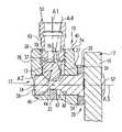
- Connector assembly 10can include coupler 24 having a body 26 for receiving elongate member 13 therethrough in a first direction.
- Body 26can also define a passage for receiving a clamping member 28 therein and permitting movement of clamping member 28 relative to body 26 in a second direction that is transversely oriented to the first direction.
- Clamping member 28includes a portion projecting from body 26 that is configured to receive at least a portion of implant 12 .
- Coupler 24can further include a washer 30 between body 26 and clamping member 28 .
- implant 16When proximal portion 16 of implant 13 is secured with coupler 24 , implant 16 can be clamped against washer 30 with the washer 30 and implant 12 clamped between implant 12 and body 26 .
- a retaining member 32can be secured to body 26 and received in a groove of clamping member 28 to axially retain clamping member 28 in body 26 while permitting clamping member 28 to move in body along the axis of clamping member 28 .
- retaining member 32can be formed unitarily with body 26 by, for example, upsetting material of body 26 , to produce a protrusion that retains clamping member 28 .
- Body 26includes a transverse passage 34 for receiving clamping member 28 therein.
- Transverse passage 34opens at each side of body 26 , although the side opposite of implant 12 could be closed.
- Body 26further includes a receiving channel 36 that extends transversely to and is in communication with passage 34 .
- channel 36forms a generally U-shape having an open end that opens at a top side of body 26 .
- the U-shapecan be defined between a first arm 38 and a second arm 40 .
- First and second arms 38 , 40each include an internal thread profile for engaging an engaging member 50 .
- Channel 36extends between and opens at each of the front and back sides of body 26 .
- Elongate member 13is positionable in channel 36 such that it projects from the front and back sides of body 26 .
- Channel 36could also be generally V-shaped or have other suitable configurations.
- Clamping member 28is received in and axially moveable in transverse passage 34 of body 26 .
- Clamping member 28includes an elongated, pin-like body having an annular groove 42 extending therearound. Groove 42 includes a bottom portion 44 and opposite inclined portions 46 , 48 extending outwardly from bottom portion 44 to the outer perimeter of clamping member 28 .
- Clamping member 28further includes a through-bore 54 extending therethrough at an outer end 52 thereof opposite groove 42 . Through-bore 54 is sized and shaped to receive proximal portion 16 of implant 12 therethrough. In the illustrated embodiment, through-bore 54 is enclosed by clamping member 28 . Other embodiments contemplate through-bore 54 having one or more open sides.
- Elongate member 13is positionable in channel 36 , and can be secured therein with engaging member 50 engaged to arms 38 , 40 .
- engaging member 50is threadingly advanced into contact with elongate member 13
- elongate member 13is forced into contact with the adjacent inclined portion 46 , 48 of clamping member 28 .
- the camming action of elongate member 13 against, for example, inclined portion 46 as shown,displaces clamping member 28 so that outer end 52 and body 26 are moved toward one another. This in turn pushes implant 12 against washer 30 .
- washer 30is firmly seated against body 26 , elongate member 13 is locked in position relative to implant 12 .
- washer 30is omitted and the implant is clamped directly against extension portion 27 of body 26 that extends toward implant 12 .
- the path along which elongate member 13 moves between arms 38 , 40can be obliquely oriented relative to at least one of the path along which engaging member 50 moves into contact with elongate member 13 and the path along which clamping member 28 moves to secure implant 12 to coupler 24 .
- the oblique path along which elongate member 13 is seated in coupler 24can direct elongate member 13 against the inclined portion 46 of clamping member 28 . This in turn axially displaces clamping member 28 , and moves implant 12 and body 26 toward one another and clampingly engage washer 30 and implant 12 between clamping member 28 and body 26 .
- the thread profile along arms 38 , 40extends along an axis A 1 that is orthogonal to axis A 2 along which elongate member 13 extends.
- Axis A 1is also orthogonal to the axis A 3 along which clamping member 28 and passage 34 extend.
- the threadsprovide a path along which engaging member 50 is directed into contact with elongate member 13 .
- Arms 38 , 40define channel 36 between channel walls 37 , 39 .
- Walls 37 , 39extend along axis A 4 , which is obliquely oriented to axis A 1 and to axis A 3 .
- Axis A 4defines the path along which elongate member 13 is moved as it is seated into contact with clamping member 28 by advancement of engaging member 50 along the path defined by axis A 1 .
- Washer 30extends about clamping member 28 along one side of body 26 adjacent extension portion 27 .
- washer 30can include radial splines that interdigitate with a corresponding splined structure on body 26 to secure washer 30 and thus elongate member 13 in position relative to body 26 when clamped thereagainst.
- washer 30can be provided in various thickness, tapers, and/or other characteristic to facilitate securement of implant 12 and elongate member 13 in the desired positioning relative to one another.
- Connector assembly 10can provide at least six degrees of adjustability of implant 12 relative to elongate member 13 .
- connector assembly 10can be axially adjusted along implant 12 in through-bore 54 of clamping member 28 , as indicated by arrow 60 .
- the orientation of body 26 and clamping member 28 relative to implant 12can be adjusted by rotating body 26 and clamping member 28 about implant 12 , as indicated by arrow 62 .
- the positioning of body 26can be rotationally adjusted about clamping member 28 by rotating body 26 thereabout, as indicated by arrow 64 .
- Connector assembly 10can also be axially adjusted along elongate member 13 in channel 36 of body 26 , as indicated by arrow 66 .
- the orientation of body 26 and clamping member 28 relative to elongate member 13can be adjusted by rotating body 26 and clamping member 28 about elongate member 13 , as indicated by arrow 68 .
- the spacing between elongate member 13 and implant 12can be adjusted along arrow 70 by providing washers of various thicknesses, tapers, or other characteristic, and/or or by increasing an offset distance provided by an extension portion 27 of body 26 that is between channel 36 and the side of the body 26 along which implant 12 extends.
- FIGS. 3 and 4show another embodiment connector assembly 100 .
- Connector assembly 100is substantially identical to connector assembly 10 discussed above.
- connector assembly 100includes a coupler 124 having a closed channel 136 that is circumscribed by the body of coupler 124 .
- the enclosed channel 136can receive elongate member 13 by end-loading the elongate member 13 into channel 136 .
- Coupler 124includes an upper bore 128 in communication with channel 136 to receive an engaging member to secure elongate member 13 therein in contact with clamping member 28 .
- Upper bore 128can define internal threads to threadingly engage engaging member 50 .
- coupler 124includes channel 136 for receiving and guiding elongate member 13 along a path defined by sidewalls 137 , 139 that is obliquely oriented to the axes along which engaging member 50 and clamping 28 are moved.
- connector assembly 10 , 100allows the positioning of coupler 24 , 124 relative to implant 12 to be adjusted as needed to accommodate the spinal anatomy.
- Medial-lateral adjustabilitycan be provided by providing coupler 24 in differing sizes and/or a washer 30 of differing sizes and tapers.
- the orientation of the portion of the implant extending through through-bore 54can be varied at various angles.
- engaging member 50includes a distal threaded portion 78 and a proximal portion 80 .
- Proximal portion 80can include a recess for receive a driving tool, or can be configured to receive a driving tool thereabout.
- Proximal portion 80can be configured to sever or break-off upon application of a threshold torque.
- Distal portion 78can include an internal bore that can receive a driving tool to facilitate removal or tightening of distal portion 78 after removal of proximal portion 80 .
- connector assembly 10 , 100can be used in surgical procedures relating to the spine.
- the surgeoncan gain access to a surgical site using any suitable technique, such as through an incision and retraction of tissue, or through minimally invasive access portals or pathways.
- One or more of the implants 12can be provided in the form of bone screws that can be threadingly implanted into one or more vertebrae, such as in the pedicle in a posterior stabilization procedure.
- Proximal portion 16can extend from the pedicle. If not pre-positioned on proximal portion 16 , clamping member 28 can be positioned on implant 12 .
- elongate member 13can be positioned in the channel thereof.
- coupler 24 , 124 with elongate member 13can be completed prior to implantation of elongate member 13 or during its implantation.
- elongate member 13can be positioned along the spinal column with the coupler secured thereto.
- the arm of the coupler and the clamping membercan be positioned to extend medial-laterally from elongate member 13 .
- the clamping member of the couplercan then be positioned over implant 12 with proximal portion 16 extending through through-bore 54 of the clamping member.
- the orientation of elongate member 13 , implant 12 , and the couplercan be adjusted relative to one another as discussed above.
- Engaging member 50is positioned to engage the coupler and threaded distally therein to contact elongate member 13 . Further advancement of engaging member 50 along the axis defined by the thread profile of the coupler moves elongate member 13 along the obliquely oriented channel of the coupler and into contact with the inclined portion 46 of groove 42 extending about clamping member 28 . This in turn moves the coupler and the implant toward one another into clamping engagement. Engaging member 50 can be further advanced until sufficient torque is applied to lock the components of connector assembly 10 , 100 with implant 12 and elongate member 13 .
- elongate member 13 and one or more connector assemblies 10 , 100 and other implants discussed hereinmay be employed unilaterally.
- a second elongate member 13 and one or more connector assemblies 10 , 100 and/or other suitable connection mechanism with other implantscan be secured to the other side of the vertebral level or levels to be stabilized.
- Multiple elongate members 13 and corresponding implant/connector assemblies 10 , 100can be secured along the same side of the spinal column in either uni-lateral or bi-lateral stabilization procedures.
- the underlying boneforms a portion of a vertebral body of the spinal column.
- the underlying bonecan be a part of the anterior, oblique, antero-lateral, lateral or posterior vertebral elements, including the pedicle, spinous process, transverse processes, lamina or facet, for example.
- Applications in techniques along any portion or portions of the spinal columnare contemplated, including the cervical, thoracic, lumbar and sacral regions.
- the connector assemblies, implants and elongate memberscan be positioned along the spinal column in invasive procedures where skin and tissue are dissected and retracted to expose the implant locations, or in minimally invasive procedures where one or more of the connector assemblies, elongate members and/or implants are guided through at least the tissue or access portals adjacent the column to the desired implantation location.
Landscapes
- Health & Medical Sciences (AREA)
- Orthopedic Medicine & Surgery (AREA)
- Life Sciences & Earth Sciences (AREA)
- Surgery (AREA)
- Neurology (AREA)
- Heart & Thoracic Surgery (AREA)
- Engineering & Computer Science (AREA)
- Biomedical Technology (AREA)
- Nuclear Medicine, Radiotherapy & Molecular Imaging (AREA)
- Medical Informatics (AREA)
- Molecular Biology (AREA)
- Animal Behavior & Ethology (AREA)
- General Health & Medical Sciences (AREA)
- Public Health (AREA)
- Veterinary Medicine (AREA)
- Surgical Instruments (AREA)
- Prostheses (AREA)
Abstract
Description
Spinal implants can be engaged to or along one or more vertebrae of the spinal column for the treatment of various spinal conditions. Fasteners can be provided to secure the implant to a particular location along the spinal column. The implants can be provided to stabilize the spinal column for treatment, either by fixing the spinal column or by permitting at least some motion of the stabilized motion segments.
Multi-axial and uni-axial screws have been employed for securing elongated implants, such as rods or plates, along one or more motion segments of the spinal column. The use of rod to bolt connectors to fix bone screws to spinal rods is another way to secure vertebrae together. Such fasteners can comprise many components or parts that make placement and manipulation of the fastener and the elongated implant cumbersome during surgery to achieve the desired position relative to the spinal anatomy. Fasteners that facilitate securement of the elongated implant in a desired positioning along the spinal column can enhance spinal stabilization procedures.
According to one aspect, a system for stabilizing a bony segment includes an elongate member positionable along the bony segment and an implant engageable to the bony segment in a transverse orientation to the elongate member. The system also includes a connector assembly for connecting the elongate member to the implant. The connector assembly includes a coupler having a body defining a channel for receiving the elongate member and a clamping member in a passage of the body. The passage extends transversely to the channel. The clamping member includes a portion extending from the body and is configured to receive the implant with the portion of the coupling member. The connector assembly also includes an engaging member movable perpendicularly to the clamping member into contact with the elongate member to contact the elongate member with the clamping member and displace the clamping member and the coupler relative to one another to clamp the implant therebetween.
According to a further aspect, a system for stabilizing a bony segment is provided. The system includes an elongate member positionable along the bony segment and an implant engageable to the bony segment in a transverse orientation to the elongate member. The system also includes a connector assembly for connecting the elongate member to the implant. The connector assembly includes a coupler having a body that defines a channel for receiving the elongate member and a passage in the body that is transversely oriented to the channel. The connector assembly further includes a clamping member in the passage that has a portion projecting from the body to receive the implant. The connector assembly also includes an engaging member threadingly engageable to the coupler in the channel along a first axis, and the clamping member extends along a second axis that is generally orthogonally oriented to the first axis. The channel extends along a third axis that is obliquely oriented to the first axis and to the second axis. When the engaging member is threaded along the first axis in the channel to contact the elongate member, the elongate member moves along the channel and against the clamping member to displace the clamping member in the passage along the second axis to clamp the implant between the clamping member and the coupler.
According to another aspect, a method for coupling an elongate member to an implant engageable to a spinal column includes: providing a coupler having a body defining a channel for receiving the elongate member therein in a first orientation, the body defining a passage extending transversely to the channel for receiving a clamping member therein, the clamping member including a portion projecting from the body to receive the implant in a transverse orientation to the elongate member; advancing an engaging member along the channel in a direction and into contact with the elongate member, wherein the channel is configured to displace the elongate member in the channel along a path obliquely oriented to the clamping member and to the direction along which the engaging member is advanced; and contacting the clamping member with the elongate member to move the clamping member and coupler relative to one another to clamp the implant between the coupler and the clamping member while securing the elongate member against the clamping member.
These and other aspects will be discussed further below.
For the purposes of promoting an understanding of the principles of the invention, reference will now be made to the embodiments illustrated in the drawings and specific language will be used to describe the same. It will nevertheless be understood that no limitation of the scope of the invention is thereby intended. Any such alterations and further modifications in the illustrated devices, and such further applications of the principles of the invention as illustrated herein are contemplated as would normally occur to one skilled in the art to which the invention relates.
As used herein, the terms top, bottom, front and back are used to refer various portions ofconnector assembly 10 and its components. Such terms refer to the orientation of the components as shown in the Figures, and are not intended to limit the orientation of the components relative to the user of the device or its relative positioning in the patient. For example, the top ofcoupler 24 can be oriented, when implanted, in an anterior, posterior, lateral, medial, oblique or other direction relative to the patient in which the assembly is implanted.
Clampingmember 28 is received in and axially moveable intransverse passage 34 ofbody 26. Clampingmember 28 includes an elongated, pin-like body having anannular groove 42 extending therearound.Groove 42 includes abottom portion 44 and oppositeinclined portions bottom portion 44 to the outer perimeter of clampingmember 28. Clampingmember 28 further includes a through-bore 54 extending therethrough at anouter end 52 thereof oppositegroove 42. Through-bore 54 is sized and shaped to receiveproximal portion 16 ofimplant 12 therethrough. In the illustrated embodiment, through-bore 54 is enclosed by clampingmember 28. Other embodiments contemplate through-bore 54 having one or more open sides.
In one embodiment, the path along which elongatemember 13 moves betweenarms member 50 moves into contact withelongate member 13 and the path along which clampingmember 28 moves to secureimplant 12 tocoupler 24. The oblique path along which elongatemember 13 is seated incoupler 24 can directelongate member 13 against theinclined portion 46 of clampingmember 28. This in turn axially displaces clampingmember 28, and movesimplant 12 andbody 26 toward one another and clampingly engagewasher 30 andimplant 12 between clampingmember 28 andbody 26.
In one embodiment, the thread profile alongarms member 13 extends. Axis A1 is also orthogonal to the axis A3 along which clampingmember 28 andpassage 34 extend. The threads provide a path along which engagingmember 50 is directed into contact withelongate member 13.Arms channel 36 betweenchannel walls Walls member 13 is moved as it is seated into contact with clampingmember 28 by advancement of engagingmember 50 along the path defined by axis A1.
The arrangement ofconnector assembly coupler coupler 24 in differing sizes and/or awasher 30 of differing sizes and tapers. Furthermore, the orientation of the portion of the implant extending through through-bore 54 can be varied at various angles.
As also shown in the Figures, engagingmember 50 includes a distal threadedportion 78 and aproximal portion 80.Proximal portion 80 can include a recess for receive a driving tool, or can be configured to receive a driving tool thereabout.Proximal portion 80 can be configured to sever or break-off upon application of a threshold torque.Distal portion 78 can include an internal bore that can receive a driving tool to facilitate removal or tightening ofdistal portion 78 after removal ofproximal portion 80.
In use,connector assembly implants 12 can be provided in the form of bone screws that can be threadingly implanted into one or more vertebrae, such as in the pedicle in a posterior stabilization procedure.Proximal portion 16 can extend from the pedicle. If not pre-positioned onproximal portion 16, clampingmember 28 can be positioned onimplant 12. Furthermore, if not already positioned incoupler elongate member 13 can be positioned in the channel thereof.
It is contemplated that assembly ofcoupler elongate member 13 can be completed prior to implantation ofelongate member 13 or during its implantation. In either case,elongate member 13 can be positioned along the spinal column with the coupler secured thereto. The arm of the coupler and the clamping member can be positioned to extend medial-laterally fromelongate member 13. The clamping member of the coupler can then be positioned overimplant 12 withproximal portion 16 extending through through-bore 54 of the clamping member. Prior to finally securing the coupler to the elongate member and the implant, the orientation ofelongate member 13,implant 12, and the coupler can be adjusted relative to one another as discussed above.
Engagingmember 50 is positioned to engage the coupler and threaded distally therein to contactelongate member 13. Further advancement of engagingmember 50 along the axis defined by the thread profile of the coupler moveselongate member 13 along the obliquely oriented channel of the coupler and into contact with theinclined portion 46 ofgroove 42 extending about clampingmember 28. This in turn moves the coupler and the implant toward one another into clamping engagement. Engagingmember 50 can be further advanced until sufficient torque is applied to lock the components ofconnector assembly implant 12 andelongate member 13.
In spinal surgical procedures,elongate member 13 and one ormore connector assemblies elongate member 13 and one ormore connector assemblies elongate members 13 and corresponding implant/connector assemblies
In one technique, the underlying bone forms a portion of a vertebral body of the spinal column. The underlying bone can be a part of the anterior, oblique, antero-lateral, lateral or posterior vertebral elements, including the pedicle, spinous process, transverse processes, lamina or facet, for example. Applications in techniques along any portion or portions of the spinal column are contemplated, including the cervical, thoracic, lumbar and sacral regions. The connector assemblies, implants and elongate members can be positioned along the spinal column in invasive procedures where skin and tissue are dissected and retracted to expose the implant locations, or in minimally invasive procedures where one or more of the connector assemblies, elongate members and/or implants are guided through at least the tissue or access portals adjacent the column to the desired implantation location.
While the invention has been illustrated and described in detail in the drawings and foregoing description, the same is to be considered as illustrative and not restrictive in character. All changes and modifications that come within the spirit of the invention are desired to be protected.
Claims (18)
1. A system for stabilizing a bony segment, comprising:
an elongate member positionable along the bony segment;
an implant engageable to the bony segment in a transverse orientation to the elongate member;
a connector assembly for connecting the elongate member to the implant, said connector assembly comprising:
a coupler having a body defining a channel for receiving the elongate member and a clamping member in a passage of said body, said passage extending transversely to said channel, said clamping member including a receiver portion extending from said body and being configured to receive said implant with said receiver portion of said clamping member; and
an engaging member movable generally perpendicularly to said clamping member into contact with said elongate member to contact said elongate member with said clamping member and displace said clamping member and said coupler relative to one another to clamp said implant therebetween wherein said implant is positioned in clamping engagement between said receiver portion of said clamping member and said coupler.
2. The system ofclaim 1 , wherein said engaging member is threadingly engageable to said coupler in said channel.
3. The system ofclaim 2 , wherein said coupler includes threads extending along a first axis for receiving said engaging member along said first axis and said clamping member extends along a second axis generally orthogonal to said first axis, said channel including opposing parallel side walls extending along a third axis obliquely oriented to said first axis and said second axis.
4. The system ofclaim 3 , wherein said channel forms a U-shape that opens on a side of said body to permit said elongate member to be loaded therein through said open side.
5. The system ofclaim 3 , wherein said channel is circumscribed by a body of said coupler and said elongate member is end-loaded into said channel.
6. The system ofclaim 1 , wherein said connector assembly includes a washer between said coupler and said implant.
7. The system ofclaim 1 , wherein said clamping member is an elongated pin having a through-hole adjacent one end of said pin for receiving said implant and an annular groove spaced from said through-hole, said elongate member being received in said annular groove when said implant is clamped between said clamping member and said coupler.
8. The system ofclaim 7 , wherein said annular groove includes a bottom portion and opposite inclined portions extending outwardly from said bottom portion to an outer perimeter of said pin.
9. The system ofclaim 7 , wherein said pin is axially retained in said passage with a retaining pin coupled to said coupler and projecting into said annular groove.
10. The system ofclaim 1 , wherein said connector assembly includes a washer positioned between said coupler and said implant, and wherein said implant is clamped against said washer and said washer is seated against said coupler when said implant is positioned in clamping engagement between said receiver portion of said clamping member and said coupler.
11. A system for stabilizing a bony segment, comprising:
an elongate member positionable along the bony segment;
an implant engageable to the bony segment in a transverse orientation to the elongate member;
a connector assembly for connecting the elongate member to the implant, said connector assembly comprising:
a coupler having a body defining a channel for receiving the elongate member and a passage in said body transversely oriented to said channel, said connector assembly further including a clamping member in said passage that includes a receiver portion projecting from said body to receive said implant;
an engaging member threadingly engageable to said coupler in said channel along a first axis and said clamping member extends along a second axis generally orthogonally oriented to said first axis, wherein said channel includes opposing parallel side walls that each extend along a third axis that is obliquely oriented to said first axis and to said second axis, and when said engaging member is threaded along said first axis in said channel to contact said elongate member, said elongate member moves along said channel and against said clamping member to displace said clamping member in said passage along said second axis to clamp said implant between said clamping member and said coupler wherein said implant is positioned in clamping engagement between said receiver portion of said clamping member and said coupler.
12. The system ofclaim 11 , wherein said channel is circumscribed by a body of said coupler and said elongate member is end-loaded into said channel.
13. The system ofclaim 11 , wherein said connector assembly includes a washer between said coupler and said implant.
14. The system ofclaim 11 , wherein said clamping member includes an elongated pin having a through-hole adjacent one end thereof for receiving said implant therethrough and an annular groove spaced from said through-hole, said elongate member being received in said annular groove when positioned against said clamping member, and wherein said annular groove includes a bottom portion and opposite inclined portions extending outwardly from said bottom portion to an outer perimeter of said pin.
15. The system ofclaim 11 , wherein said elongate member is a spinal rod and said implant is a bone screw with a distal bone engaging portion engageable to a vertebra and a proximal portion received by said clamping member.
16. The system ofclaim 11 , wherein said connector assembly includes a washer positioned between said coupler and said implant, and wherein said implant is clamped against said washer and said washer is seated against said coupler when said implant is positioned in clamping engagement between said receiver portion of said clamping member and said coupler.
17. The system ofclaim 11 , wherein said clamping member is an elongated pin having a through-hole adjacent one end of said pin for receiving said implant and an annular groove spaced from said through-hole, said elongate member being received in said annular groove when said implant is clamped between said clamping member and said coupler.
18. A system for stabilizing a bony segment, comprising:
an elongate member positionable along the bony segment;
an implant engageable to the bony segment in a transverse orientation to the elongate member;
a connector assembly for connecting the elongate member to the implant, said connector assembly comprising:
a coupler having a body defining a channel for receiving the elongate member and a passage in said body transversely oriented to said channel, wherein said channel forms a U-shape that opens along a side of said body and said elongate member can be positioned into said channel through said open side; and
said connector assembly further including a clamping member in said passage that includes a portion projecting from said body to receive said implant;
an engaging member threadingly engageable to said coupler in said channel along a first axis and said clamping member extends along a second axis generally orthogonally oriented to said first axis, wherein said channel extends along a third axis that is obliquely oriented to said first axis and to said second axis, and when said engaging member is threaded along said first axis in said channel to contact said elongate member, said elongate member moves along said channel and against said clamping member to displace said clamping member in said passage along said second axis to clamp said implant between said clamping member and said coupler.
Priority Applications (6)
| Application Number | Priority Date | Filing Date | Title |
|---|---|---|---|
| US11/322,824US7575587B2 (en) | 2005-12-30 | 2005-12-30 | Top-tightening side-locking spinal connector assembly |
| PCT/US2006/062226WO2007079356A1 (en) | 2005-12-30 | 2006-12-18 | Top-tightening side-locking spinal connector assembly |
| JP2008548809AJP2009522021A (en) | 2005-12-30 | 2006-12-18 | Spinal connector assembly that fastens the top and locks the sides |
| AU2006332577AAU2006332577A1 (en) | 2005-12-30 | 2006-12-18 | Top-tightening side-locking spinal connector assembly |
| EP20060840304EP1976443B1 (en) | 2005-12-30 | 2006-12-18 | Top-tightening side-locking spinal connector assembly |
| KR1020087018647AKR101382545B1 (en) | 2005-12-30 | 2006-12-18 | Top-tightening side-locking spinal connector assembly |
Applications Claiming Priority (1)
| Application Number | Priority Date | Filing Date | Title |
|---|---|---|---|
| US11/322,824US7575587B2 (en) | 2005-12-30 | 2005-12-30 | Top-tightening side-locking spinal connector assembly |
Publications (2)
| Publication Number | Publication Date |
|---|---|
| US20070156142A1 US20070156142A1 (en) | 2007-07-05 |
| US7575587B2true US7575587B2 (en) | 2009-08-18 |
Family
ID=37853054
Family Applications (1)
| Application Number | Title | Priority Date | Filing Date |
|---|---|---|---|
| US11/322,824Active2027-09-22US7575587B2 (en) | 2005-12-30 | 2005-12-30 | Top-tightening side-locking spinal connector assembly |
Country Status (6)
| Country | Link |
|---|---|
| US (1) | US7575587B2 (en) |
| EP (1) | EP1976443B1 (en) |
| JP (1) | JP2009522021A (en) |
| KR (1) | KR101382545B1 (en) |
| AU (1) | AU2006332577A1 (en) |
| WO (1) | WO2007079356A1 (en) |
Cited By (66)
| Publication number | Priority date | Publication date | Assignee | Title |
|---|---|---|---|---|
| US20060149245A1 (en)* | 2004-06-09 | 2006-07-06 | Spinal Generations, Llc | Bone fixation system |
| US20060195096A1 (en)* | 2005-02-09 | 2006-08-31 | David Lee | Bone fixation apparatus |
| US20070055239A1 (en)* | 2004-06-09 | 2007-03-08 | Spinal Generations, Llc | Spinal fixation system |
| US20070238335A1 (en)* | 2006-04-05 | 2007-10-11 | Sdgi Holdings, Inc. | Lateral connector assembly |
| US20080262553A1 (en)* | 2007-04-18 | 2008-10-23 | Ebi, Llc | Spinal connector |
| US20100160971A1 (en)* | 2008-12-23 | 2010-06-24 | Chad Glerum | Variable Angle Connection Assembly |
| US20100191293A1 (en)* | 2003-06-18 | 2010-07-29 | Jackson Roger P | Polyaxial bone anchor with spline capture connection and lower pressure insert |
| US20110040338A1 (en)* | 2003-08-28 | 2011-02-17 | Jackson Roger P | Polyaxial bone anchor having an open retainer with conical, cylindrical or curvate capture |
| US20110172713A1 (en)* | 2010-01-12 | 2011-07-14 | Michael Harper | Offset Variable Angle Connection Assembly |
| US20110196425A1 (en)* | 2010-02-05 | 2011-08-11 | Warsaw Orthopedic, Inc. | Connector and Method |
| US20120029566A1 (en)* | 2010-07-28 | 2012-02-02 | Warsaw Orthopedic, Inc. | Adjustable spinal connector assembly |
| US8137386B2 (en) | 2003-08-28 | 2012-03-20 | Jackson Roger P | Polyaxial bone screw apparatus |
| US20120109209A1 (en)* | 2010-10-29 | 2012-05-03 | Warsaw Orthopedic, Inc. | Spinal Connector Assembly |
| US20120221055A1 (en)* | 2009-03-26 | 2012-08-30 | Spontech Spine Intelligence Group Ag | Spine Fixation System |
| US8308782B2 (en) | 2004-11-23 | 2012-11-13 | Jackson Roger P | Bone anchors with longitudinal connecting member engaging inserts and closures for fixation and optional angulation |
| US8377067B2 (en) | 2004-02-27 | 2013-02-19 | Roger P. Jackson | Orthopedic implant rod reduction tool set and method |
| US8388660B1 (en) | 2006-08-01 | 2013-03-05 | Samy Abdou | Devices and methods for superior fixation of orthopedic devices onto the vertebral column |
| US8394133B2 (en) | 2004-02-27 | 2013-03-12 | Roger P. Jackson | Dynamic fixation assemblies with inner core and outer coil-like member |
| US8398682B2 (en) | 2003-06-18 | 2013-03-19 | Roger P. Jackson | Polyaxial bone screw assembly |
| US8444681B2 (en) | 2009-06-15 | 2013-05-21 | Roger P. Jackson | Polyaxial bone anchor with pop-on shank, friction fit retainer and winged insert |
| US8556938B2 (en) | 2009-06-15 | 2013-10-15 | Roger P. Jackson | Polyaxial bone anchor with non-pivotable retainer and pop-on shank, some with friction fit |
| US8814913B2 (en) | 2002-09-06 | 2014-08-26 | Roger P Jackson | Helical guide and advancement flange with break-off extensions |
| US8814911B2 (en) | 2003-06-18 | 2014-08-26 | Roger P. Jackson | Polyaxial bone screw with cam connection and lock and release insert |
| US8894657B2 (en) | 2004-02-27 | 2014-11-25 | Roger P. Jackson | Tool system for dynamic spinal implants |
| US8911479B2 (en) | 2012-01-10 | 2014-12-16 | Roger P. Jackson | Multi-start closures for open implants |
| US8936623B2 (en) | 2003-06-18 | 2015-01-20 | Roger P. Jackson | Polyaxial bone screw assembly |
| US8940032B2 (en) | 2011-10-26 | 2015-01-27 | Globus Medical, Inc. | Connection assembly |
| US8998959B2 (en) | 2009-06-15 | 2015-04-07 | Roger P Jackson | Polyaxial bone anchors with pop-on shank, fully constrained friction fit retainer and lock and release insert |
| US9005249B2 (en) | 2011-07-11 | 2015-04-14 | Life Spine, Inc. | Spinal rod connector assembly |
| US9050139B2 (en) | 2004-02-27 | 2015-06-09 | Roger P. Jackson | Orthopedic implant rod reduction tool set and method |
| US9168069B2 (en) | 2009-06-15 | 2015-10-27 | Roger P. Jackson | Polyaxial bone anchor with pop-on shank and winged insert with lower skirt for engaging a friction fit retainer |
| US9216039B2 (en) | 2004-02-27 | 2015-12-22 | Roger P. Jackson | Dynamic spinal stabilization assemblies, tool set and method |
| US9393047B2 (en) | 2009-06-15 | 2016-07-19 | Roger P. Jackson | Polyaxial bone anchor with pop-on shank and friction fit retainer with low profile edge lock |
| US9414863B2 (en) | 2005-02-22 | 2016-08-16 | Roger P. Jackson | Polyaxial bone screw with spherical capture, compression insert and alignment and retention structures |
| US9480517B2 (en) | 2009-06-15 | 2016-11-01 | Roger P. Jackson | Polyaxial bone anchor with pop-on shank, shank, friction fit retainer, winged insert and low profile edge lock |
| US9629669B2 (en) | 2004-11-23 | 2017-04-25 | Roger P. Jackson | Spinal fixation tool set and method |
| US9743957B2 (en) | 2004-11-10 | 2017-08-29 | Roger P. Jackson | Polyaxial bone screw with shank articulation pressure insert and method |
| US9820780B2 (en) | 2015-09-30 | 2017-11-21 | Amendia, Inc. | Angled offset tulip assembly |
| US9907574B2 (en) | 2008-08-01 | 2018-03-06 | Roger P. Jackson | Polyaxial bone anchors with pop-on shank, friction fit fully restrained retainer, insert and tool receiving features |
| US9980753B2 (en) | 2009-06-15 | 2018-05-29 | Roger P Jackson | pivotal anchor with snap-in-place insert having rotation blocking extensions |
| US10039577B2 (en) | 2004-11-23 | 2018-08-07 | Roger P Jackson | Bone anchor receiver with horizontal radiused tool attachment structures and parallel planar outer surfaces |
| US10039578B2 (en) | 2003-12-16 | 2018-08-07 | DePuy Synthes Products, Inc. | Methods and devices for minimally invasive spinal fixation element placement |
| US20180280063A1 (en)* | 2017-03-28 | 2018-10-04 | Medos International Sarl | Articulating implant connectors and related methods |
| US10194951B2 (en) | 2005-05-10 | 2019-02-05 | Roger P. Jackson | Polyaxial bone anchor with compound articulation and pop-on shank |
| US10219840B2 (en) | 2015-04-06 | 2019-03-05 | Choice Spine, Llc | Pedicle screw and multi-axial connector system |
| US10299839B2 (en) | 2003-12-16 | 2019-05-28 | Medos International Sárl | Percutaneous access devices and bone anchor assemblies |
| US10363070B2 (en) | 2009-06-15 | 2019-07-30 | Roger P. Jackson | Pivotal bone anchor assemblies with pressure inserts and snap on articulating retainers |
| US10492835B2 (en) | 2016-12-19 | 2019-12-03 | Medos International Sàrl | Offset rods, offset rod connectors, and related methods |
| US10517647B2 (en) | 2016-05-18 | 2019-12-31 | Medos International Sarl | Implant connectors and related methods |
| US10543107B2 (en) | 2009-12-07 | 2020-01-28 | Samy Abdou | Devices and methods for minimally invasive spinal stabilization and instrumentation |
| US10548740B1 (en) | 2016-10-25 | 2020-02-04 | Samy Abdou | Devices and methods for vertebral bone realignment |
| US10561454B2 (en) | 2017-03-28 | 2020-02-18 | Medos International Sarl | Articulating implant connectors and related methods |
| US10575961B1 (en) | 2011-09-23 | 2020-03-03 | Samy Abdou | Spinal fixation devices and methods of use |
| US10695105B2 (en) | 2012-08-28 | 2020-06-30 | Samy Abdou | Spinal fixation devices and methods of use |
| US10857003B1 (en) | 2015-10-14 | 2020-12-08 | Samy Abdou | Devices and methods for vertebral stabilization |
| US10869695B2 (en) | 2017-02-10 | 2020-12-22 | Medos International Sarl | Tandem rod connectors and related methods |
| US10918498B2 (en) | 2004-11-24 | 2021-02-16 | Samy Abdou | Devices and methods for inter-vertebral orthopedic device placement |
| US10973648B1 (en) | 2016-10-25 | 2021-04-13 | Samy Abdou | Devices and methods for vertebral bone realignment |
| US11006982B2 (en) | 2012-02-22 | 2021-05-18 | Samy Abdou | Spinous process fixation devices and methods of use |
| US11058463B2 (en) | 2016-05-18 | 2021-07-13 | Medos International Sarl | Implant connectors and related methods |
| US11076890B2 (en) | 2017-12-01 | 2021-08-03 | Medos International Sàrl | Rod-to-rod connectors having robust rod closure mechanisms and related methods |
| US11173040B2 (en) | 2012-10-22 | 2021-11-16 | Cogent Spine, LLC | Devices and methods for spinal stabilization and instrumentation |
| US11179248B2 (en) | 2018-10-02 | 2021-11-23 | Samy Abdou | Devices and methods for spinal implantation |
| US11419642B2 (en) | 2003-12-16 | 2022-08-23 | Medos International Sarl | Percutaneous access devices and bone anchor assemblies |
| US20220387082A1 (en)* | 2020-10-28 | 2022-12-08 | Globus Medical, Inc. | Articulating connectors, systems, and methods thereof |
| US12383311B2 (en) | 2010-05-14 | 2025-08-12 | Roger P. Jackson | Pivotal bone anchor assembly and method for use thereof |
Families Citing this family (28)
| Publication number | Priority date | Publication date | Assignee | Title |
|---|---|---|---|---|
| US7833250B2 (en) | 2004-11-10 | 2010-11-16 | Jackson Roger P | Polyaxial bone screw with helically wound capture connection |
| US6520962B1 (en)* | 2000-10-23 | 2003-02-18 | Sdgi Holdings, Inc. | Taper-locked adjustable connector |
| US8876868B2 (en) | 2002-09-06 | 2014-11-04 | Roger P. Jackson | Helical guide and advancement flange with radially loaded lip |
| US7377923B2 (en) | 2003-05-22 | 2008-05-27 | Alphatec Spine, Inc. | Variable angle spinal screw assembly |
| US8366753B2 (en) | 2003-06-18 | 2013-02-05 | Jackson Roger P | Polyaxial bone screw assembly with fixed retaining structure |
| US7967850B2 (en) | 2003-06-18 | 2011-06-28 | Jackson Roger P | Polyaxial bone anchor with helical capture connection, insert and dual locking assembly |
| US11241261B2 (en) | 2005-09-30 | 2022-02-08 | Roger P Jackson | Apparatus and method for soft spinal stabilization using a tensionable cord and releasable end structure |
| US7651502B2 (en) | 2004-09-24 | 2010-01-26 | Jackson Roger P | Spinal fixation tool set and method for rod reduction and fastener insertion |
| US8926672B2 (en) | 2004-11-10 | 2015-01-06 | Roger P. Jackson | Splay control closure for open bone anchor |
| WO2006057837A1 (en) | 2004-11-23 | 2006-06-01 | Jackson Roger P | Spinal fixation tool attachment structure |
| US7901437B2 (en) | 2007-01-26 | 2011-03-08 | Jackson Roger P | Dynamic stabilization member with molded connection |
| US7789895B2 (en)* | 2006-12-26 | 2010-09-07 | Warsaw Orthopedic, Inc. | Sacral reconstruction fixation device |
| US20100049253A1 (en)* | 2008-08-20 | 2010-02-25 | Warsaw Orthopedic, Inc. | Bottom loading connector for attaching a spinal rod to a vertebral member |
| US9668771B2 (en) | 2009-06-15 | 2017-06-06 | Roger P Jackson | Soft stabilization assemblies with off-set connector |
| US11229457B2 (en) | 2009-06-15 | 2022-01-25 | Roger P. Jackson | Pivotal bone anchor assembly with insert tool deployment |
| US8317834B2 (en)* | 2010-01-28 | 2012-11-27 | Warsaw Orthopedic, Inc. | Pre-assembled construct for insertion into a patient |
| US20120029571A1 (en) | 2010-07-29 | 2012-02-02 | Warsaw Orthopedic, Inc. | Adjustable Connector for Interconnecting Elongate Rod Members at Variable Angular Orientations |
| DE102012016294B4 (en) | 2012-08-16 | 2014-02-27 | Spontech Spine Intelligence Group Ag | Polyaxial connector for spinal fixation systems and spine fixation system |
| US8911478B2 (en) | 2012-11-21 | 2014-12-16 | Roger P. Jackson | Splay control closure for open bone anchor |
| US10058354B2 (en) | 2013-01-28 | 2018-08-28 | Roger P. Jackson | Pivotal bone anchor assembly with frictional shank head seating surfaces |
| US8852239B2 (en) | 2013-02-15 | 2014-10-07 | Roger P Jackson | Sagittal angle screw with integral shank and receiver |
| US9566092B2 (en) | 2013-10-29 | 2017-02-14 | Roger P. Jackson | Cervical bone anchor with collet retainer and outer locking sleeve |
| US9717533B2 (en) | 2013-12-12 | 2017-08-01 | Roger P. Jackson | Bone anchor closure pivot-splay control flange form guide and advancement structure |
| US9451993B2 (en) | 2014-01-09 | 2016-09-27 | Roger P. Jackson | Bi-radial pop-on cervical bone anchor |
| US10064658B2 (en) | 2014-06-04 | 2018-09-04 | Roger P. Jackson | Polyaxial bone anchor with insert guides |
| US9597119B2 (en) | 2014-06-04 | 2017-03-21 | Roger P. Jackson | Polyaxial bone anchor with polymer sleeve |
| CN107854170B (en)* | 2017-11-14 | 2020-03-10 | 山东威高骨科材料股份有限公司 | Connector and locking mechanism thereof |
| US11311317B2 (en)* | 2019-09-25 | 2022-04-26 | Stelios KOUTSOUMBELIS | Spinal fixation device with rotatable connector |
Citations (25)
| Publication number | Priority date | Publication date | Assignee | Title |
|---|---|---|---|---|
| US4569338A (en) | 1984-02-09 | 1986-02-11 | Edwards Charles C | Sacral fixation device |
| US4827918A (en) | 1985-08-15 | 1989-05-09 | Sven Olerud | Fixing instrument for use in spinal surgery |
| US5047029A (en) | 1988-06-10 | 1991-09-10 | Synthes (U.S.A.) | Clamp and system for internal fixation |
| US5053034A (en) | 1990-08-03 | 1991-10-01 | Sven Olerud | Spinal joint |
| US5254118A (en)* | 1991-12-04 | 1993-10-19 | Srdjian Mirkovic | Three dimensional spine fixation system |
| US5527314A (en) | 1993-01-04 | 1996-06-18 | Danek Medical, Inc. | Spinal fixation system |
| WO1997006742A1 (en) | 1995-08-14 | 1997-02-27 | Peter Melott Simonson | Spinal implant connection assembly |
| US5643264A (en) | 1995-09-13 | 1997-07-01 | Danek Medical, Inc. | Iliac screw |
| US5645544A (en) | 1995-09-13 | 1997-07-08 | Danek Medical, Inc. | Variable angle extension rod |
| US5690630A (en) | 1995-04-13 | 1997-11-25 | Fastenetix, Llc | Polyaxial pedicle screw |
| US5741255A (en)* | 1996-06-05 | 1998-04-21 | Acromed Corporation | Spinal column retaining apparatus |
| US5797911A (en) | 1996-09-24 | 1998-08-25 | Sdgi Holdings, Inc. | Multi-axial bone screw assembly |
| US5947967A (en) | 1997-10-22 | 1999-09-07 | Sdgt Holdings, Inc. | Variable angle connector |
| US6183473B1 (en) | 1999-04-21 | 2001-02-06 | Richard B Ashman | Variable angle connection assembly for a spinal implant system |
| US6210413B1 (en) | 1999-04-23 | 2001-04-03 | Sdgi Holdings, Inc. | Connecting apparatus using shape-memory technology |
| US6231575B1 (en)* | 1998-08-27 | 2001-05-15 | Martin H. Krag | Spinal column retainer |
| US6248107B1 (en) | 2000-03-15 | 2001-06-19 | Sdgi Holdings, Inc. | System for reducing the displacement of a vertebra |
| US6520962B1 (en) | 2000-10-23 | 2003-02-18 | Sdgi Holdings, Inc. | Taper-locked adjustable connector |
| US6562038B1 (en) | 2000-03-15 | 2003-05-13 | Sdgi Holdings, Inc. | Spinal implant connection assembly |
| US6669697B1 (en)* | 1998-09-25 | 2003-12-30 | Perumala Corporation | Self-retaining bolt for internal spinal stabilizers |
| US6685705B1 (en) | 2000-10-23 | 2004-02-03 | Sdgi Holdings, Inc. | Six-axis and seven-axis adjustable connector |
| US6755830B2 (en)* | 2001-07-04 | 2004-06-29 | Sofamor S.N.C. | Connector for a spinal fixation member |
| USRE39035E1 (en)* | 1994-11-18 | 2006-03-21 | Howmedica Osteonics Corp. | Universal coupler for spinal fixation |
| US20060155278A1 (en)* | 2004-10-25 | 2006-07-13 | Alphaspine, Inc. | Pedicle screw systems and methods of assembling/installing the same |
| US20070043357A1 (en)* | 2005-07-29 | 2007-02-22 | X-Spine Systems, Inc. | Capless multiaxial screw and spinal fixation assembly and method |
- 2005
- 2005-12-30USUS11/322,824patent/US7575587B2/enactiveActive
- 2006
- 2006-12-18AUAU2006332577Apatent/AU2006332577A1/ennot_activeAbandoned
- 2006-12-18JPJP2008548809Apatent/JP2009522021A/enactivePending
- 2006-12-18WOPCT/US2006/062226patent/WO2007079356A1/enactiveApplication Filing
- 2006-12-18EPEP20060840304patent/EP1976443B1/enactiveActive
- 2006-12-18KRKR1020087018647Apatent/KR101382545B1/ennot_activeExpired - Fee Related
Patent Citations (29)
| Publication number | Priority date | Publication date | Assignee | Title |
|---|---|---|---|---|
| US4569338A (en) | 1984-02-09 | 1986-02-11 | Edwards Charles C | Sacral fixation device |
| US4827918A (en) | 1985-08-15 | 1989-05-09 | Sven Olerud | Fixing instrument for use in spinal surgery |
| US5047029A (en) | 1988-06-10 | 1991-09-10 | Synthes (U.S.A.) | Clamp and system for internal fixation |
| US5053034A (en) | 1990-08-03 | 1991-10-01 | Sven Olerud | Spinal joint |
| US5254118A (en)* | 1991-12-04 | 1993-10-19 | Srdjian Mirkovic | Three dimensional spine fixation system |
| US5527314A (en) | 1993-01-04 | 1996-06-18 | Danek Medical, Inc. | Spinal fixation system |
| US5534002A (en) | 1993-01-04 | 1996-07-09 | Danek Medical, Inc. | Spinal fixation system |
| US5562662A (en) | 1993-01-04 | 1996-10-08 | Danek Medical Inc. | Spinal fixation system and method |
| USRE39035E1 (en)* | 1994-11-18 | 2006-03-21 | Howmedica Osteonics Corp. | Universal coupler for spinal fixation |
| US5690630A (en) | 1995-04-13 | 1997-11-25 | Fastenetix, Llc | Polyaxial pedicle screw |
| US5643263A (en) | 1995-08-14 | 1997-07-01 | Simonson; Peter Melott | Spinal implant connection assembly |
| WO1997006742A1 (en) | 1995-08-14 | 1997-02-27 | Peter Melott Simonson | Spinal implant connection assembly |
| US5885285A (en) | 1995-08-14 | 1999-03-23 | Simonson; Peter Melott | Spinal implant connection assembly |
| US5643264A (en) | 1995-09-13 | 1997-07-01 | Danek Medical, Inc. | Iliac screw |
| US5645544A (en) | 1995-09-13 | 1997-07-08 | Danek Medical, Inc. | Variable angle extension rod |
| US5741255A (en)* | 1996-06-05 | 1998-04-21 | Acromed Corporation | Spinal column retaining apparatus |
| US5797911A (en) | 1996-09-24 | 1998-08-25 | Sdgi Holdings, Inc. | Multi-axial bone screw assembly |
| US5947967A (en) | 1997-10-22 | 1999-09-07 | Sdgt Holdings, Inc. | Variable angle connector |
| US6231575B1 (en)* | 1998-08-27 | 2001-05-15 | Martin H. Krag | Spinal column retainer |
| US6669697B1 (en)* | 1998-09-25 | 2003-12-30 | Perumala Corporation | Self-retaining bolt for internal spinal stabilizers |
| US6183473B1 (en) | 1999-04-21 | 2001-02-06 | Richard B Ashman | Variable angle connection assembly for a spinal implant system |
| US6210413B1 (en) | 1999-04-23 | 2001-04-03 | Sdgi Holdings, Inc. | Connecting apparatus using shape-memory technology |
| US6248107B1 (en) | 2000-03-15 | 2001-06-19 | Sdgi Holdings, Inc. | System for reducing the displacement of a vertebra |
| US6562038B1 (en) | 2000-03-15 | 2003-05-13 | Sdgi Holdings, Inc. | Spinal implant connection assembly |
| US6520962B1 (en) | 2000-10-23 | 2003-02-18 | Sdgi Holdings, Inc. | Taper-locked adjustable connector |
| US6685705B1 (en) | 2000-10-23 | 2004-02-03 | Sdgi Holdings, Inc. | Six-axis and seven-axis adjustable connector |
| US6755830B2 (en)* | 2001-07-04 | 2004-06-29 | Sofamor S.N.C. | Connector for a spinal fixation member |
| US20060155278A1 (en)* | 2004-10-25 | 2006-07-13 | Alphaspine, Inc. | Pedicle screw systems and methods of assembling/installing the same |
| US20070043357A1 (en)* | 2005-07-29 | 2007-02-22 | X-Spine Systems, Inc. | Capless multiaxial screw and spinal fixation assembly and method |
Cited By (130)
| Publication number | Priority date | Publication date | Assignee | Title |
|---|---|---|---|---|
| US8814913B2 (en) | 2002-09-06 | 2014-08-26 | Roger P Jackson | Helical guide and advancement flange with break-off extensions |
| US8936623B2 (en) | 2003-06-18 | 2015-01-20 | Roger P. Jackson | Polyaxial bone screw assembly |
| US8814911B2 (en) | 2003-06-18 | 2014-08-26 | Roger P. Jackson | Polyaxial bone screw with cam connection and lock and release insert |
| US8398682B2 (en) | 2003-06-18 | 2013-03-19 | Roger P. Jackson | Polyaxial bone screw assembly |
| US20100191293A1 (en)* | 2003-06-18 | 2010-07-29 | Jackson Roger P | Polyaxial bone anchor with spline capture connection and lower pressure insert |
| US8377102B2 (en) | 2003-06-18 | 2013-02-19 | Roger P. Jackson | Polyaxial bone anchor with spline capture connection and lower pressure insert |
| US20110040338A1 (en)* | 2003-08-28 | 2011-02-17 | Jackson Roger P | Polyaxial bone anchor having an open retainer with conical, cylindrical or curvate capture |
| US8137386B2 (en) | 2003-08-28 | 2012-03-20 | Jackson Roger P | Polyaxial bone screw apparatus |
| US11426216B2 (en) | 2003-12-16 | 2022-08-30 | DePuy Synthes Products, Inc. | Methods and devices for minimally invasive spinal fixation element placement |
| US10039578B2 (en) | 2003-12-16 | 2018-08-07 | DePuy Synthes Products, Inc. | Methods and devices for minimally invasive spinal fixation element placement |
| US10299839B2 (en) | 2003-12-16 | 2019-05-28 | Medos International Sárl | Percutaneous access devices and bone anchor assemblies |
| US11419642B2 (en) | 2003-12-16 | 2022-08-23 | Medos International Sarl | Percutaneous access devices and bone anchor assemblies |
| US8377067B2 (en) | 2004-02-27 | 2013-02-19 | Roger P. Jackson | Orthopedic implant rod reduction tool set and method |
| US8894657B2 (en) | 2004-02-27 | 2014-11-25 | Roger P. Jackson | Tool system for dynamic spinal implants |
| US8394133B2 (en) | 2004-02-27 | 2013-03-12 | Roger P. Jackson | Dynamic fixation assemblies with inner core and outer coil-like member |
| US9216039B2 (en) | 2004-02-27 | 2015-12-22 | Roger P. Jackson | Dynamic spinal stabilization assemblies, tool set and method |
| US9918751B2 (en) | 2004-02-27 | 2018-03-20 | Roger P. Jackson | Tool system for dynamic spinal implants |
| US9050139B2 (en) | 2004-02-27 | 2015-06-09 | Roger P. Jackson | Orthopedic implant rod reduction tool set and method |
| US9055978B2 (en) | 2004-02-27 | 2015-06-16 | Roger P. Jackson | Orthopedic implant rod reduction tool set and method |
| US9168151B2 (en) | 2004-06-09 | 2015-10-27 | Life Spine, Inc. | Spinal fixation system |
| US20070055239A1 (en)* | 2004-06-09 | 2007-03-08 | Spinal Generations, Llc | Spinal fixation system |
| US8021398B2 (en)* | 2004-06-09 | 2011-09-20 | Life Spine, Inc. | Spinal fixation system |
| US8617209B2 (en) | 2004-06-09 | 2013-12-31 | Life Spine, Inc. | Spinal fixation system |
| US20060149245A1 (en)* | 2004-06-09 | 2006-07-06 | Spinal Generations, Llc | Bone fixation system |
| US20110004251A1 (en)* | 2004-06-09 | 2011-01-06 | Life Spine, Inc. | Spinal fixation system |
| US9743957B2 (en) | 2004-11-10 | 2017-08-29 | Roger P. Jackson | Polyaxial bone screw with shank articulation pressure insert and method |
| US10039577B2 (en) | 2004-11-23 | 2018-08-07 | Roger P Jackson | Bone anchor receiver with horizontal radiused tool attachment structures and parallel planar outer surfaces |
| US8308782B2 (en) | 2004-11-23 | 2012-11-13 | Jackson Roger P | Bone anchors with longitudinal connecting member engaging inserts and closures for fixation and optional angulation |
| US9629669B2 (en) | 2004-11-23 | 2017-04-25 | Roger P. Jackson | Spinal fixation tool set and method |
| US8840652B2 (en) | 2004-11-23 | 2014-09-23 | Roger P. Jackson | Bone anchors with longitudinal connecting member engaging inserts and closures for fixation and optional angulation |
| US11389214B2 (en) | 2004-11-23 | 2022-07-19 | Roger P. Jackson | Spinal fixation tool set and method |
| US11992423B2 (en) | 2004-11-24 | 2024-05-28 | Samy Abdou | Devices and methods for inter-vertebral orthopedic device placement |
| US10918498B2 (en) | 2004-11-24 | 2021-02-16 | Samy Abdou | Devices and methods for inter-vertebral orthopedic device placement |
| US11096799B2 (en) | 2004-11-24 | 2021-08-24 | Samy Abdou | Devices and methods for inter-vertebral orthopedic device placement |
| US7896905B2 (en)* | 2005-02-09 | 2011-03-01 | David Lee | Bone fixation apparatus |
| US20060195096A1 (en)* | 2005-02-09 | 2006-08-31 | David Lee | Bone fixation apparatus |
| USRE47551E1 (en) | 2005-02-22 | 2019-08-06 | Roger P. Jackson | Polyaxial bone screw with spherical capture, compression insert and alignment and retention structures |
| US9414863B2 (en) | 2005-02-22 | 2016-08-16 | Roger P. Jackson | Polyaxial bone screw with spherical capture, compression insert and alignment and retention structures |
| US10194951B2 (en) | 2005-05-10 | 2019-02-05 | Roger P. Jackson | Polyaxial bone anchor with compound articulation and pop-on shank |
| US20070238335A1 (en)* | 2006-04-05 | 2007-10-11 | Sdgi Holdings, Inc. | Lateral connector assembly |
| US7753940B2 (en)* | 2006-04-05 | 2010-07-13 | Warsaw Orthopedic, Inc. | Lateral connector assembly |
| US8388660B1 (en) | 2006-08-01 | 2013-03-05 | Samy Abdou | Devices and methods for superior fixation of orthopedic devices onto the vertebral column |
| US10792074B2 (en) | 2007-01-22 | 2020-10-06 | Roger P. Jackson | Pivotal bone anchor assemly with twist-in-place friction fit insert |
| US8337527B2 (en)* | 2007-04-18 | 2012-12-25 | Ebi, Llc | Spinal connector |
| US20080262553A1 (en)* | 2007-04-18 | 2008-10-23 | Ebi, Llc | Spinal connector |
| US9907574B2 (en) | 2008-08-01 | 2018-03-06 | Roger P. Jackson | Polyaxial bone anchors with pop-on shank, friction fit fully restrained retainer, insert and tool receiving features |
| US20100160971A1 (en)* | 2008-12-23 | 2010-06-24 | Chad Glerum | Variable Angle Connection Assembly |
| US9814492B2 (en) | 2008-12-23 | 2017-11-14 | Globus Medical, Inc. | Variable angle connection assembly |
| US11116549B2 (en) | 2008-12-23 | 2021-09-14 | Globus Medical, Inc. | Variable angle connection assembly |
| US8529605B2 (en) | 2008-12-23 | 2013-09-10 | Globus Medical, Inc. | Variable angle connection assembly |
| US8066746B2 (en) | 2008-12-23 | 2011-11-29 | Globus Medical, Inc. | Variable angle connection assembly |
| US10420589B2 (en) | 2008-12-23 | 2019-09-24 | Globus Medical, Inc. | Variable angle connection assembly |
| US9408640B2 (en) | 2008-12-23 | 2016-08-09 | Globus Medical, Inc | Variable angle connection assembly |
| US20120221055A1 (en)* | 2009-03-26 | 2012-08-30 | Spontech Spine Intelligence Group Ag | Spine Fixation System |
| US8556938B2 (en) | 2009-06-15 | 2013-10-15 | Roger P. Jackson | Polyaxial bone anchor with non-pivotable retainer and pop-on shank, some with friction fit |
| US9918745B2 (en) | 2009-06-15 | 2018-03-20 | Roger P. Jackson | Polyaxial bone anchor with pop-on shank and winged insert with friction fit compressive collet |
| US9480517B2 (en) | 2009-06-15 | 2016-11-01 | Roger P. Jackson | Polyaxial bone anchor with pop-on shank, shank, friction fit retainer, winged insert and low profile edge lock |
| US10363070B2 (en) | 2009-06-15 | 2019-07-30 | Roger P. Jackson | Pivotal bone anchor assemblies with pressure inserts and snap on articulating retainers |
| US9504496B2 (en) | 2009-06-15 | 2016-11-29 | Roger P. Jackson | Polyaxial bone anchor with pop-on shank, friction fit retainer and winged insert |
| US9393047B2 (en) | 2009-06-15 | 2016-07-19 | Roger P. Jackson | Polyaxial bone anchor with pop-on shank and friction fit retainer with low profile edge lock |
| US9168069B2 (en) | 2009-06-15 | 2015-10-27 | Roger P. Jackson | Polyaxial bone anchor with pop-on shank and winged insert with lower skirt for engaging a friction fit retainer |
| US8998959B2 (en) | 2009-06-15 | 2015-04-07 | Roger P Jackson | Polyaxial bone anchors with pop-on shank, fully constrained friction fit retainer and lock and release insert |
| US9980753B2 (en) | 2009-06-15 | 2018-05-29 | Roger P Jackson | pivotal anchor with snap-in-place insert having rotation blocking extensions |
| US8444681B2 (en) | 2009-06-15 | 2013-05-21 | Roger P. Jackson | Polyaxial bone anchor with pop-on shank, friction fit retainer and winged insert |
| US10610380B2 (en) | 2009-12-07 | 2020-04-07 | Samy Abdou | Devices and methods for minimally invasive spinal stabilization and instrumentation |
| US10857004B2 (en) | 2009-12-07 | 2020-12-08 | Samy Abdou | Devices and methods for minimally invasive spinal stabilization and instrumentation |
| US10543107B2 (en) | 2009-12-07 | 2020-01-28 | Samy Abdou | Devices and methods for minimally invasive spinal stabilization and instrumentation |
| US11918486B2 (en) | 2009-12-07 | 2024-03-05 | Samy Abdou | Devices and methods for minimally invasive spinal stabilization and instrumentation |
| US10945861B2 (en) | 2009-12-07 | 2021-03-16 | Samy Abdou | Devices and methods for minimally invasive spinal stabilization and instrumentation |
| US9011496B2 (en) | 2010-01-12 | 2015-04-21 | Globus Medical, Inc. | Offset variable angle connection assembly |
| US8070781B2 (en) | 2010-01-12 | 2011-12-06 | Globus Medical, Inc. | Offset variable angle connection assembly |
| WO2011088063A1 (en)* | 2010-01-12 | 2011-07-21 | Globus Medical, Inc. | Offset variable angle connection assembly |
| US10058356B2 (en) | 2010-01-12 | 2018-08-28 | Globus Medical, Inc. | Offset variable angle connection assembly |
| US9271762B2 (en) | 2010-01-12 | 2016-03-01 | Globus Medical, Inc. | Offset variable angle connection assembly |
| US20110172713A1 (en)* | 2010-01-12 | 2011-07-14 | Michael Harper | Offset Variable Angle Connection Assembly |
| US8808331B2 (en) | 2010-01-12 | 2014-08-19 | Globus Medical, Inc. | Offset variable angle connection assembly |
| US20110196425A1 (en)* | 2010-02-05 | 2011-08-11 | Warsaw Orthopedic, Inc. | Connector and Method |
| US8317837B2 (en) | 2010-02-05 | 2012-11-27 | Warsaw Orthopedic, Inc. | Connector and method |
| US12383311B2 (en) | 2010-05-14 | 2025-08-12 | Roger P. Jackson | Pivotal bone anchor assembly and method for use thereof |
| US8480713B2 (en)* | 2010-07-28 | 2013-07-09 | Warsaw Orthopedic, Inc. | Adjustable spinal connector assembly |
| US20120029566A1 (en)* | 2010-07-28 | 2012-02-02 | Warsaw Orthopedic, Inc. | Adjustable spinal connector assembly |
| US8246658B2 (en)* | 2010-10-29 | 2012-08-21 | Warsaw Orthopedic, Inc. | Spinal connector assembly |
| US20120109209A1 (en)* | 2010-10-29 | 2012-05-03 | Warsaw Orthopedic, Inc. | Spinal Connector Assembly |
| US9005249B2 (en) | 2011-07-11 | 2015-04-14 | Life Spine, Inc. | Spinal rod connector assembly |
| US11517449B2 (en) | 2011-09-23 | 2022-12-06 | Samy Abdou | Spinal fixation devices and methods of use |
| US12167973B2 (en) | 2011-09-23 | 2024-12-17 | Samy Abdou | Spinal fixation devices and methods of use |
| US10575961B1 (en) | 2011-09-23 | 2020-03-03 | Samy Abdou | Spinal fixation devices and methods of use |
| US11324608B2 (en) | 2011-09-23 | 2022-05-10 | Samy Abdou | Spinal fixation devices and methods of use |
| US8940032B2 (en) | 2011-10-26 | 2015-01-27 | Globus Medical, Inc. | Connection assembly |
| US9168067B2 (en) | 2011-10-26 | 2015-10-27 | Globus Medical Inc. | Connection assembly |
| US11272960B2 (en) | 2011-10-26 | 2022-03-15 | Globus Medical Inc. | Connection assembly |
| US10765457B2 (en) | 2011-10-26 | 2020-09-08 | Globus Medical Inc. | Connection assembly |
| US10143497B2 (en) | 2011-10-26 | 2018-12-04 | Globus Medical, Inc. | Connection assembly |
| US9498257B2 (en) | 2011-10-26 | 2016-11-22 | Globus Medical, Inc. | Connection assembly |
| US8911479B2 (en) | 2012-01-10 | 2014-12-16 | Roger P. Jackson | Multi-start closures for open implants |
| US11006982B2 (en) | 2012-02-22 | 2021-05-18 | Samy Abdou | Spinous process fixation devices and methods of use |
| US11839413B2 (en) | 2012-02-22 | 2023-12-12 | Samy Abdou | Spinous process fixation devices and methods of use |
| US11559336B2 (en) | 2012-08-28 | 2023-01-24 | Samy Abdou | Spinal fixation devices and methods of use |
| US10695105B2 (en) | 2012-08-28 | 2020-06-30 | Samy Abdou | Spinal fixation devices and methods of use |
| US11173040B2 (en) | 2012-10-22 | 2021-11-16 | Cogent Spine, LLC | Devices and methods for spinal stabilization and instrumentation |
| US11918483B2 (en) | 2012-10-22 | 2024-03-05 | Cogent Spine Llc | Devices and methods for spinal stabilization and instrumentation |
| US10219840B2 (en) | 2015-04-06 | 2019-03-05 | Choice Spine, Llc | Pedicle screw and multi-axial connector system |
| US11103287B1 (en) | 2015-04-06 | 2021-08-31 | Choice Spine, Llc | Pedicle screw and multi-axial connector system |
| US9820780B2 (en) | 2015-09-30 | 2017-11-21 | Amendia, Inc. | Angled offset tulip assembly |
| US11246718B2 (en) | 2015-10-14 | 2022-02-15 | Samy Abdou | Devices and methods for vertebral stabilization |
| US10857003B1 (en) | 2015-10-14 | 2020-12-08 | Samy Abdou | Devices and methods for vertebral stabilization |
| US11596451B2 (en) | 2016-05-18 | 2023-03-07 | Medos International Sarl | Implant connectors and related methods |
| US11058463B2 (en) | 2016-05-18 | 2021-07-13 | Medos International Sarl | Implant connectors and related methods |
| US10517647B2 (en) | 2016-05-18 | 2019-12-31 | Medos International Sarl | Implant connectors and related methods |
| US10973648B1 (en) | 2016-10-25 | 2021-04-13 | Samy Abdou | Devices and methods for vertebral bone realignment |
| US10744000B1 (en) | 2016-10-25 | 2020-08-18 | Samy Abdou | Devices and methods for vertebral bone realignment |
| US10548740B1 (en) | 2016-10-25 | 2020-02-04 | Samy Abdou | Devices and methods for vertebral bone realignment |
| US11259935B1 (en) | 2016-10-25 | 2022-03-01 | Samy Abdou | Devices and methods for vertebral bone realignment |
| US11058548B1 (en) | 2016-10-25 | 2021-07-13 | Samy Abdou | Devices and methods for vertebral bone realignment |
| US11752008B1 (en) | 2016-10-25 | 2023-09-12 | Samy Abdou | Devices and methods for vertebral bone realignment |
| US11160583B2 (en) | 2016-12-19 | 2021-11-02 | Medos International Sarl | Offset rods, offset rod connectors, and related methods |
| US12150679B2 (en) | 2016-12-19 | 2024-11-26 | Medos International Srl | Offset rods, offset rod connectors, and related methods |
| US10492835B2 (en) | 2016-12-19 | 2019-12-03 | Medos International Sàrl | Offset rods, offset rod connectors, and related methods |
| US10869695B2 (en) | 2017-02-10 | 2020-12-22 | Medos International Sarl | Tandem rod connectors and related methods |
| US11793554B2 (en) | 2017-02-10 | 2023-10-24 | Medos International Sarl | Tandem rod connectors and related methods |
| US11382676B2 (en) | 2017-03-28 | 2022-07-12 | Medos International Sarl | Articulating implant connectors and related methods |
| US11707304B2 (en)* | 2017-03-28 | 2023-07-25 | Medos International Sarl | Articulating implant connectors and related methods |
| US10561454B2 (en) | 2017-03-28 | 2020-02-18 | Medos International Sarl | Articulating implant connectors and related methods |
| US10966761B2 (en)* | 2017-03-28 | 2021-04-06 | Medos International Sarl | Articulating implant connectors and related methods |
| US12059187B2 (en) | 2017-03-28 | 2024-08-13 | Medos International Sarl | Articulating implant connectors and related methods |
| US20180280063A1 (en)* | 2017-03-28 | 2018-10-04 | Medos International Sarl | Articulating implant connectors and related methods |
| US20210186572A1 (en)* | 2017-03-28 | 2021-06-24 | Medos International Sarl | Articulating implant connectors and related methods |
| US11076890B2 (en) | 2017-12-01 | 2021-08-03 | Medos International Sàrl | Rod-to-rod connectors having robust rod closure mechanisms and related methods |
| US11179248B2 (en) | 2018-10-02 | 2021-11-23 | Samy Abdou | Devices and methods for spinal implantation |
| US20220387082A1 (en)* | 2020-10-28 | 2022-12-08 | Globus Medical, Inc. | Articulating connectors, systems, and methods thereof |
Also Published As
| Publication number | Publication date |
|---|---|
| KR101382545B1 (en) | 2014-04-07 |
| US20070156142A1 (en) | 2007-07-05 |
| AU2006332577A1 (en) | 2007-07-12 |
| EP1976443B1 (en) | 2015-05-20 |
| EP1976443A1 (en) | 2008-10-08 |
| WO2007079356A1 (en) | 2007-07-12 |
| JP2009522021A (en) | 2009-06-11 |
| KR20080089613A (en) | 2008-10-07 |
Similar Documents
| Publication | Publication Date | Title |
|---|---|---|
| US7575587B2 (en) | Top-tightening side-locking spinal connector assembly | |
| KR101326119B1 (en) | Coupling assemblies for spinal implants | |
| US8029546B2 (en) | Variable angle offset spinal connector assembly | |
| EP1991144B1 (en) | Dorsal adjusting spinal connector assembly | |
| US7794481B2 (en) | Force limiting coupling assemblies for spinal implants | |
| US8915945B2 (en) | Adjustable multi-axial spinal coupling assemblies | |
| US10039578B2 (en) | Methods and devices for minimally invasive spinal fixation element placement | |
| US7967821B2 (en) | Break-off screw extension removal tools | |
| US20110166606A1 (en) | Reduction tool | |
| KR200370921Y1 (en) | Pedicle Screw System | |
| AU2013200841A1 (en) | Coupling assemblies for spinal implants |
Legal Events
| Date | Code | Title | Description |
|---|---|---|---|
| AS | Assignment | Owner name:SDGI HOLDINGS, INC., DELAWARE Free format text:ASSIGNMENT OF ASSIGNORS INTEREST;ASSIGNORS:REZACH, ALAN;MORRISON, MATHEW M.;BRUMFIELD, DAVID L.;REEL/FRAME:017436/0250;SIGNING DATES FROM 20051223 TO 20051229 | |
| AS | Assignment | Owner name:WARSAW ORTHOPEDIC, INC., INDIANA Free format text:MERGER;ASSIGNOR:SDGI HOLDINGS, INC.;REEL/FRAME:020558/0116 Effective date:20060428 Owner name:WARSAW ORTHOPEDIC, INC.,INDIANA Free format text:MERGER;ASSIGNOR:SDGI HOLDINGS, INC.;REEL/FRAME:020558/0116 Effective date:20060428 | |
| STCF | Information on status: patent grant | Free format text:PATENTED CASE | |
| CC | Certificate of correction | ||
| FPAY | Fee payment | Year of fee payment:4 | |
| FPAY | Fee payment | Year of fee payment:8 | |
| MAFP | Maintenance fee payment | Free format text:PAYMENT OF MAINTENANCE FEE, 12TH YEAR, LARGE ENTITY (ORIGINAL EVENT CODE: M1553); ENTITY STATUS OF PATENT OWNER: LARGE ENTITY Year of fee payment:12 |