US7575380B2 - Integrated optical fiber and electro-optical converter - Google Patents
Integrated optical fiber and electro-optical converterDownload PDFInfo
- Publication number
- US7575380B2 US7575380B2US10/965,984US96598404AUS7575380B2US 7575380 B2US7575380 B2US 7575380B2US 96598404 AUS96598404 AUS 96598404AUS 7575380 B2US7575380 B2US 7575380B2
- Authority
- US
- United States
- Prior art keywords
- signal
- cable
- optical
- channels
- electrical connector
- Prior art date
- Legal status (The legal status is an assumption and is not a legal conclusion. Google has not performed a legal analysis and makes no representation as to the accuracy of the status listed.)
- Expired - Fee Related
Links
Images


Classifications
- G—PHYSICS
- G02—OPTICS
- G02B—OPTICAL ELEMENTS, SYSTEMS OR APPARATUS
- G02B6/00—Light guides; Structural details of arrangements comprising light guides and other optical elements, e.g. couplings
- G02B6/24—Coupling light guides
- G02B6/42—Coupling light guides with opto-electronic elements
- G02B6/4201—Packages, e.g. shape, construction, internal or external details
- G—PHYSICS
- G02—OPTICS
- G02B—OPTICAL ELEMENTS, SYSTEMS OR APPARATUS
- G02B6/00—Light guides; Structural details of arrangements comprising light guides and other optical elements, e.g. couplings
- G02B6/24—Coupling light guides
- G02B6/36—Mechanical coupling means
- G02B6/38—Mechanical coupling means having fibre to fibre mating means
- G02B6/3807—Dismountable connectors, i.e. comprising plugs
- G02B6/381—Dismountable connectors, i.e. comprising plugs of the ferrule type, e.g. fibre ends embedded in ferrules, connecting a pair of fibres
- G02B6/3817—Dismountable connectors, i.e. comprising plugs of the ferrule type, e.g. fibre ends embedded in ferrules, connecting a pair of fibres containing optical and electrical conductors
- G—PHYSICS
- G02—OPTICS
- G02B—OPTICAL ELEMENTS, SYSTEMS OR APPARATUS
- G02B6/00—Light guides; Structural details of arrangements comprising light guides and other optical elements, e.g. couplings
- G02B6/24—Coupling light guides
- G02B6/42—Coupling light guides with opto-electronic elements
- G02B6/4201—Packages, e.g. shape, construction, internal or external details
- G02B6/4202—Packages, e.g. shape, construction, internal or external details for coupling an active element with fibres without intermediate optical elements, e.g. fibres with plane ends, fibres with shaped ends, bundles
- G—PHYSICS
- G02—OPTICS
- G02B—OPTICAL ELEMENTS, SYSTEMS OR APPARATUS
- G02B6/00—Light guides; Structural details of arrangements comprising light guides and other optical elements, e.g. couplings
- G02B6/24—Coupling light guides
- G02B6/42—Coupling light guides with opto-electronic elements
- G02B6/4201—Packages, e.g. shape, construction, internal or external details
- G02B6/4249—Packages, e.g. shape, construction, internal or external details comprising arrays of active devices and fibres
- G—PHYSICS
- G02—OPTICS
- G02B—OPTICAL ELEMENTS, SYSTEMS OR APPARATUS
- G02B6/00—Light guides; Structural details of arrangements comprising light guides and other optical elements, e.g. couplings
- G02B6/44—Mechanical structures for providing tensile strength and external protection for fibres, e.g. optical transmission cables
- G02B6/4401—Optical cables
- G02B6/4415—Cables for special applications
- G02B6/4416—Heterogeneous cables
Definitions
- the present inventionrelates to high speed data communications cables, and more particularly to optical fiber cables and electro-optical signal converters used for short-range coupling of information system units.
- High speed data communications networksutilize optical fiber cables for data transmission between information system units such as computers, mass data storage devices, and routers. Such units typically employ electrical connectors which couple to electrical connectors associated with electrical cables. To couple such units to an optical fiber cable, an electro-optical converter or transceiver is employed which interfaces between the electrical connector and the optical fiber cable.
- FIGS. 1A and 1BExamples of electrical connectors know in the prior art communications applications are illustrated in FIGS. 1A and 1B . More particularly, FIG. 1A shows an electrical connector 10 designed for use in a 4-channel InfiniBandTM electrical interconnect. FIG. 1B shows an electrical connector plug 12 designed for use in a 12-channel InfiniBandTM electrical interconnect. Electrical connectors 10 and 12 are inserted in associated electrical receptacles mounted on an information systems unit to establish electrical contact with the input/output terminals of such unit
- FIGS. 2A and 2Brespectively show an optical cable connector 14 and an optical cable connector receptacle 16 used in InfiniBandTM 4-channel and 12-channel optical interconnects.
- the optical connector 14is adapted to mate with optical connector receptacle 16 to enable the four independent optical signals traveling through four fibers in the attached optical cable 18 to communicate with corresponding receivers disposed in the optical connector receptacle 16 .
- the committee setting standards for both 10 Giga-bit Fiber Channel (10 GFC) and 10 Giga-bit Ethernet (10 GbE)is considering to use the above described electrical and optical connector plugs/receptacles in systems complying with these standards.
- FIG. 3shows a conventional InfiniBandTM interface card 20 that is adapted to be inserted in system 22 .
- the InfiniBandTM interface card 20is commonly referred to as a Host-Channel Adapter (HCA) or a Target Channel Adapter (TCA).
- HCAHost-Channel Adapter
- TCATarget Channel Adapter
- Each InfiniBandTM interface card 20includes one or more printed circuit boards (PCB) that are alternatively referred to hereinbelow as host broads.
- PCBprinted circuit boards
- Each such PCBtypically includes hardware adapted to establish communication with other PCBs, with other interface cards or modules via a multitude of electrical wires or optical cables.
- FIG. 4Ashows an electrical connector receptacle 24 mounted on a host board 26 of a TCA/HCA card. Electrical connector receptacle 24 is adapted so as to mate with electrical connector plug 10 (also see FIG. 1A ).
- FIG. 4Bshows an optical connector receptacle 28 mounted on a host board 30 of a TCA/HCA card. Optical connector receptacle 28 is adapted so as to mate with optical connector plug 14 (also see FIG. 2A ).
- the host boardis often adapted to mate with either an electrical connector plug or an optical connector plug. If the host board is adapted to mate with an electrical connector plug and a subsequent need arises to carry the signals over distances longer than those for which electrical wires, i.e., copper may be used (InfiniBandTM specification calls for copper wire to be used for distances up to 17 meters), the user may need to replace the TCA/HCA card with a card adapted to receive an optical cable so as to be able to handle optical signals, thereby increasing cost.
- electrical wiresi.e., copper may be used
- the host board cardis adapted to mate with an optical connector plug, and a subsequent need arises to carry the signals over a relatively shorter distances, it may be more cost effective to replace the TCA/HCA card with a card adapted to receive a copper wire so as to be able to handle electrical signals.
- media adaptershave been developed to enable optical signals carried via an optical cable to be coupled to electrical receptacles.
- Such media adaptersinclude a fiber optic cable with an electrical plug coupled to on one end and an optical plug coupled to another end.
- the electrical plugis adapted to mate with an electrical connector receptacle on a host board and the optical plug is adapted to mate with an optical connector receptacle.
- the electrical signals present on the electrical receptacleare converted to optical signals by a transceiver disposed in the media adapter and carried over fiber optic cable.
- Conventional media adaptersare connectorized and are thus relatively expensive. Furthermore, safety issues remain a concern if a user detaches the optical cable from the coupling plugs and looks at the light beams emanating from the lasers disposed therein.
- the present inventionprovides a communications cable for providing a short range, high speed data communications link between information system units including an optical fiber with an integral housing at each end having an electrical connector extending from the housing and adapted to mate with a corresponding electrical connector on an external information system unit for transferring an information signal between the cable and the unit; and a signal converter in the integral housing connected to the electrical connector for converting an information signal between an electrical signal and a corresponding optical signal.
- a cable assemblyincludes a fiber optic cable with a pair of optical connector plugs coupled to each one of its ends. The optical connector plugs are adapted to mate with two electrical connector receptacles already present on two host boards.
- the cable assemblythus enables communication between the electrical receptacles of the two host boards to be carried out via optical signals.
- the cable assemblyis adapted to receive electrical signals from a first electrical receptacle—mounted on the first host board—via one of its optical connector plugs, and subsequently convert the received electrical signals to optical signals and deliver the optical signals via the fiber optic cable to the other optical connector plug.
- the receiving optical connector plugconverts the optical signals to electrical signals and delivers the converted electrical signal to the second electrical connector receptacle mounted on the second host board.
- the electrical connector receptaclehas physical and electrical characteristics defined by the same standard as that defining the physical and electrical characteristic of the optical plugs. Accordingly, the same electrical receptacle on the host board may be used to receive both an electrical connector plug or the optical connector plug of the cable assembly. Accordingly, if the distance between the two electrical connector receptacles (i.e., the two host boards) is, e.g., more than 15 meters, a cable assembly, in accordance with the present invention, may be used to establish communication between the two host boards. If, on the other hand, the distance between the two host boards is, e.g., less than 15 meters, a conventional copper cable with standard electrical connector plugs may be used to establish communication between the two host boards.
- Each optical plugincludes, in part, an optical engine mounted on a board, a top housing shell, and a bottom housing shell.
- the fiber optic cableis attached to the optical plugs via a strain relief boot. Because the fiber optic cable is attached to the optical plugs and may not be easily removed, the user is not exposed to safety hazards that may result from viewing the laser beams. In other embodiments, the fiber optic cable is glued to the optical plugs.
- a cable assemblyincludes, in part, a connector plug from which a fiber optic cable and an electrical cable are fanned out.
- the connector plugreceives and processes (e.g., amplify, filter, etc.) electrical signals from an electrical connector receptacle mounted on a host board.
- the processed signals that are to be transmitted via the fiber optic cableare converted to optical signals using an optical engine.
- the processed signals that are to be transmitted via the electrical cablemay be further processed before being transmitted.
- the signals transmitted by the fiber optic cablemay be the same as those transmitted by the electrical cable and may include the entire set of the signals received from the connector receptacle.
- the signals transmitted by the fiber optic cablemay be different from those transmitted by the electrical cable.
- the optical engines as well as the integrated circuitsare powered by circuitry disposed on the host boards via the same supply voltages which power the components on the host boards.
- One or more of the connectors of the electrical receptaclesare configured to deliver the supply voltages to the optical engines as well as the integrated circuits mounted on one or more boards disposed within the connector plug and configured to process the received electrical signals.
- FIG. 1Ashows an electrical connector plug adapted for use in a 4-channel InfiniBandTM electrical interconnects, as known in the prior art.
- FIG. 1Bshows an electrical connector plug adapted for use in a 12-channel InfiniBandTM electrical interconnects, as known in the prior art.
- FIG. 2Ashows an optical connector plug used in InfiniBandTM interconnects, as known in the prior art.
- FIG. 2Bshows an optical connector receptacle used in InfiniBandTM interconnects, as known in the prior art.
- FIG. 3shows a conventional InfiniBandTM interface card.
- FIG. 4Ashows an electrical connector receptacle mounted on a host board, and an electrical connector plug adapted to mate therewith.
- FIG. 4Bshows an optical connector receptacle mounted on a host board, and an optical connector plug adapted to mate therewith.
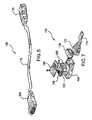
- FIG. 5shows a cable assembly, in accordance with a first embodiment of the present invention.
- FIG. 6shows the cable assembly of FIG. 5 positioned to establish communications between a pair of electrical connector receptacles mounted on two different host boards.
- FIG. 7is an exploded view of one exemplary embodiment of the optical connector plug of the cable assembly of FIG. 5 .
- FIG. 8is an exploded view of another exemplary embodiment of the optical connector plug of the cable assembly of FIG. 5 .
- a cable assemblyincludes a fiber optic cable with a pair of optical connector plugs coupled to each one of its ends.
- the optical connector plugsare adapted to mate with two electrical connector receptacles already present on two host boards.
- the cable assemblythus enables communication between the electrical receptacles of the two host boards to be carried out via optical signals.
- the cable assemblyis adapted to receive electrical signals from a first electrical receptacle—mounted on the first host board—via one of its optical connector plugs, and subsequently convert the received electrical signals to optical signals and deliver the optical signals via the fiber optic cable to the other optical connector plug.
- the receiving connector plugconverts the optical signals to electrical signals and delivers the converted electrical signal to the second electrical connector receptacle mounted on the second host board.
- the electrical connector receptaclehas physical and electrical characteristics defined by the same standard as that defining the physical and electrical characteristic of the optical plugs. Accordingly, the same electrical receptacle on the host board may be used to receive both an electrical connector plug or the optical connector plug of the cable assembly. Accordingly, if the distance between the two electrical connector receptacles (i.e., the two host boards) is, e.g., more than 15 meters, a cable assembly, in accordance with the present invention, may be used to establish communication between the two host boards. If, on the other hand, the distance between the two host boards is, e.g., less than 15 meters, a conventional copper cable with standard electrical connector plugs may be used to establish communication between the two host boards.
- FIG. 5shows a cable assembly 100 , in accordance with one embodiment of the present invention.
- Cable assembly 100includes, in part, a fiber optic cable 110 , a first optical connector plug 105 coupled to a first end of fiber optic cable 110 , and a second optical connector plug 115 coupled to a second end of fiber optic cable 110 .
- Each of the optical connector plugs (hereinafter alternatively referred to as optical plug) 105 , and 115is adapted to mate with a different electrical connector receptacle mounted on a host board, such as electrical receptacle 104 of host board 106 , shown in FIG. 6 .
- cable assembly 100is shown as being in alignment with electrical receptacle 104 —mounted on host board 106 —and electrical receptacle 108 that is mounted on electrical host board 110 . If the distance d between host board 106 and 110 is less than the maximum recommended distance for which copper cable is adapted to be used, a copper cable (not shown), such as Category 5 cable, may be used to connect electrical receptacle 104 with electrical receptacle 108 in order to establish communication between these two electrical receptacles.
- a copper cable(not shown), such as Category 5 cable
- connector plug 105is mated directly with electrical receptacle 104 and connector plug 115 is mated directly with electrical receptacle 108 in order to establish communication between these two electrical receptacles.
- each optical engineDisposed within each plug 105 and 115 of cable assembly 100 is an electrical/optical engine (hereinafter alternatively referred to as optical engine) adapted to convert electrical signals to optical signals and vice versa.
- each optical engineincludes components such as, lasers, lenses, laser drivers, etc.
- the optical engine in each optical plug, e.g. optical plug 105is adapted to receive electrical signals from its mating electrical receptacle, e.g., electrical receptacle 104 , convert that electrical signal to optical signal, and thereafter deliver that optical signal via fiber optic cable 110 to the other optical plug, e.g., optical plug 115 .
- the optical plug 115 receiving the optical signalconverts the received optical signal to electrical signal and delivers the converted electrical signal to, e.g., electrical receptacle 108 .
- FIG. 7is an exploded view of one exemplary embodiment 150 of each of optical plugs 105 , 110 .
- Optical plug 150is shown as including, in part, an optical engine 180 mounted on board 152 , top housing shell 160 , bottom housing shell 166 sleeve 170 , and strain relief boot 172 .
- the optical engine 150is mounted and secured to board 152 . Thereafter, the board 152 is disposed between top and bottom housing members 160 and 166 . It is understood that board 152 may be a flexible circuit board or a rigid circuit board.
- the optical engine 180is an optical transceiver, however, in other embodiments, the optical engine 180 may be an optical transmitter or an optical receiver.
- a train relief boot 172is adapted to prevent fiber optic cable 110 from being detached from optical plug 150 . Since fiber optic cable 110 is attached to optical plug 150 and may not be easily removed, the user is not exposed to safety hazards that may result from viewing the laser beams present therein.
- Optical plug 150complies with the same industry standard with which host board 106 and electrical receptacle 104 also comply. For example, if host board 106 and electrical receptacle 104 are formed in accordance with InfiniBandTM specifications, optical plug 150 is also compliant with InfiniBandTM specifications. If host board 106 and electrical receptacle 104 are formed so as to comply with Host-Channel Adapter (HCA) or a Target Channel Adapter (TCA) specifications and standards, optical plug 150 is also compliant with these specifications and standards. Therefore, board 152 is formed so as to receive any standard compliant optical engine.
- HCAHost-Channel Adapter
- TCATarget Channel Adapter
- FIG. 8is an exploded view of another exemplary embodiment 190 of each of optical plugs 105 , 110 .
- Optical plug 190is shown as including, in part, an optical engine 180 mounted on board 152 , top housing shell 160 , bottom housing shell 166 , and sleeve 170 .
- fiber optic cable 110is affixed to optical plug 190 via glue 191 , or other adhesive, so as not to be easily removed. The user is therefore not exposed to safety hazards that may result from viewing the laser beams.
- the glue used in accordance with this embodimentis adapted to maintain its properties under a wide range of temperatures and is available from a number of vendors, such as 3M Co, located at 3M Center, St. Paul, Minn., 55144, USA.
- optical engine 180may be supplied or manufactured by any commercial vendor or manufacturer so long as it complies with the same standard as that with which host board 106 or electrical receptacle 104 are also adapted to comply.
- fiber optic cable 110is not connectorized (i.e., fiber optic cable 110 may not be detached from the optical plugs) it provides a relatively high level of eye safety. Furthermore, because fiber optic cable 110 is not connectorized, it has improved matched ends properties, as described further below.
- a first optical engine coupled to a first end of the optical cableis required to operate with any optical engine coupled to the other end of the optical cable, notwithstanding their respective manufactures. Therefore, the first optical engine is required to function over a wide range of operating conditions, resulting in yield loss and a relatively more extensive testing.
- the two optical engines disposed at the two ends of cable assembly 100are only required to operate with each other, they are easier two match; in other words, cable assembly 100 has matched ends.
- the two optical enginesare matched, a higher manufacturing yield is achieved and less extensive testing of the optical engines are required.
- optical engine 180is mounted to board 152 via a fastener, such as a screw or bolt.
- optical engine 180may be, for example, soldered to board 152 .
- optical engine 180may have four-channels. In yet other embodiments, optical engine 180 may have, e.g., twelve channels.
- the above embodiments of the present inventionare illustrative and not limitative.
- the inventionin not limited by the type of optical engine disposed in the optical plug of each end of the assembly cable.
- the inventionis not limited by the type of circuit board, flexible or rigid, on which the optical engine is mounted.
- the inventionis not limited by the number of channels, speed or specific electrical or optical configuration that, e.g., the optical engine is adapted to handle.
- Other variations, modifications, additions, deletionsare obvious in light of the above disclosure and are intended to fall within the scope of the appended claims.
Landscapes
- Physics & Mathematics (AREA)
- General Physics & Mathematics (AREA)
- Optics & Photonics (AREA)
- Optical Couplings Of Light Guides (AREA)
- Connector Housings Or Holding Contact Members (AREA)
Abstract
Description
Claims (21)
Priority Applications (3)
| Application Number | Priority Date | Filing Date | Title |
|---|---|---|---|
| US10/965,984US7575380B2 (en) | 2004-10-15 | 2004-10-15 | Integrated optical fiber and electro-optical converter |
| US11/836,519US7581891B2 (en) | 2004-10-15 | 2007-08-09 | Laser adjustment in integrated optoelectronic modules/fiber optic cables |
| US11/854,319US7494287B2 (en) | 2004-10-15 | 2007-09-12 | Integrated optical fiber and electro-optical converter |
Applications Claiming Priority (1)
| Application Number | Priority Date | Filing Date | Title |
|---|---|---|---|
| US10/965,984US7575380B2 (en) | 2004-10-15 | 2004-10-15 | Integrated optical fiber and electro-optical converter |
Related Parent Applications (1)
| Application Number | Title | Priority Date | Filing Date |
|---|---|---|---|
| US11/732,996Continuation-In-PartUS7787767B2 (en) | 2004-10-15 | 2007-04-05 | Eye safety in electro-optical transceivers |
Related Child Applications (2)
| Application Number | Title | Priority Date | Filing Date |
|---|---|---|---|
| US11/836,519Continuation-In-PartUS7581891B2 (en) | 2004-10-15 | 2007-08-09 | Laser adjustment in integrated optoelectronic modules/fiber optic cables |
| US11/854,319DivisionUS7494287B2 (en) | 2004-10-15 | 2007-09-12 | Integrated optical fiber and electro-optical converter |
Publications (2)
| Publication Number | Publication Date |
|---|---|
| US20060088251A1 US20060088251A1 (en) | 2006-04-27 |
| US7575380B2true US7575380B2 (en) | 2009-08-18 |
Family
ID=36206248
Family Applications (2)
| Application Number | Title | Priority Date | Filing Date |
|---|---|---|---|
| US10/965,984Expired - Fee RelatedUS7575380B2 (en) | 2004-10-15 | 2004-10-15 | Integrated optical fiber and electro-optical converter |
| US11/854,319Expired - Fee RelatedUS7494287B2 (en) | 2004-10-15 | 2007-09-12 | Integrated optical fiber and electro-optical converter |
Family Applications After (1)
| Application Number | Title | Priority Date | Filing Date |
|---|---|---|---|
| US11/854,319Expired - Fee RelatedUS7494287B2 (en) | 2004-10-15 | 2007-09-12 | Integrated optical fiber and electro-optical converter |
Country Status (1)
| Country | Link |
|---|---|
| US (2) | US7575380B2 (en) |
Cited By (6)
| Publication number | Priority date | Publication date | Assignee | Title |
|---|---|---|---|---|
| US20070237468A1 (en)* | 2006-04-10 | 2007-10-11 | Aronson Lewis B | Active optical cable electrical adaptor |
| US20090060424A1 (en)* | 2007-08-29 | 2009-03-05 | Hirose Electric Co., Ltd. | Optoelectronic combination connector |
| US20100167647A1 (en)* | 2008-12-26 | 2010-07-01 | Askey Computer Corp. | Framework of wireless network access device |
| US8734026B2 (en) | 2011-08-19 | 2014-05-27 | Teledyne Instruments, Inc. | Subsea electro-optical connector unit for electro-optical ethernet transmission system |
| US9583865B2 (en)* | 2015-01-16 | 2017-02-28 | Te Connectivity Corporation | Pluggable module for a communication system |
| US20240231000A1 (en)* | 2020-02-25 | 2024-07-11 | Senko Advanced Components, Inc. | Optical signal connector |
Families Citing this family (49)
| Publication number | Priority date | Publication date | Assignee | Title |
|---|---|---|---|---|
| US7347632B2 (en)* | 2003-12-12 | 2008-03-25 | Mina Farr | Optical connectors for electronic devices |
| US7548675B2 (en) | 2004-09-29 | 2009-06-16 | Finisar Corporation | Optical cables for consumer electronics |
| US7706692B2 (en)* | 2004-09-29 | 2010-04-27 | Finisar Corporation | Consumer electronics with optical communication interface |
| US7575380B2 (en)* | 2004-10-15 | 2009-08-18 | Emcore Corporation | Integrated optical fiber and electro-optical converter |
| US20060280055A1 (en)* | 2005-06-08 | 2006-12-14 | Miller Rodney D | Laser power control and device status monitoring for video/graphic applications |
| US7331819B2 (en)* | 2005-07-11 | 2008-02-19 | Finisar Corporation | Media converter |
| US7729618B2 (en)* | 2005-08-30 | 2010-06-01 | Finisar Corporation | Optical networks for consumer electronics |
| US7860398B2 (en)* | 2005-09-15 | 2010-12-28 | Finisar Corporation | Laser drivers for closed path optical cables |
| US7186144B1 (en)* | 2005-12-01 | 2007-03-06 | Adc Telecommunications, Inc. | Connector including media converter |
| US7499616B2 (en)* | 2006-04-10 | 2009-03-03 | Finisar Corporation | Active optical cable with electrical connector |
| US7778510B2 (en) | 2006-04-10 | 2010-08-17 | Finisar Corporation | Active optical cable electrical connector |
| US7401985B2 (en) | 2006-04-10 | 2008-07-22 | Finisar Corporation | Electrical-optical active optical cable |
| US7445389B2 (en) | 2006-04-10 | 2008-11-04 | Finisar Corporation | Active optical cable with integrated eye safety |
| US7876989B2 (en)* | 2006-04-10 | 2011-01-25 | Finisar Corporation | Active optical cable with integrated power |
| US7712976B2 (en) | 2006-04-10 | 2010-05-11 | Finisar Corporation | Active optical cable with integrated retiming |
| US8398314B2 (en)* | 2007-03-30 | 2013-03-19 | Intel Corporation | Optical universal serial bus (USB) |
| US8769171B2 (en)* | 2007-04-06 | 2014-07-01 | Finisar Corporation | Electrical device with electrical interface that is compatible with integrated optical cable receptacle |
| US8244124B2 (en) | 2007-04-30 | 2012-08-14 | Finisar Corporation | Eye safety mechanism for use in optical cable with electrical interfaces |
| JP4962152B2 (en)* | 2007-06-15 | 2012-06-27 | 日立電線株式会社 | Opto-electric composite transmission assembly |
| WO2009036332A1 (en)* | 2007-09-14 | 2009-03-19 | Asuragen, Inc. | Micrornas differentially expressed in cervical cancer and uses thereof |
| US20090129725A1 (en)* | 2007-11-20 | 2009-05-21 | Durrant Richard C E | SFP Active fiber patch cord with over-molded strain relief and conductive housing |
| US7905664B1 (en)* | 2008-09-25 | 2011-03-15 | Lockheed Martin Corporation | Input/output connector having an active electrical/optical communication component |
| US20100178054A1 (en)* | 2009-01-12 | 2010-07-15 | Cisco Technology, Inc. | Ethernet/optical signal converter using power over ethernet |
| CN106130646B (en) | 2009-03-05 | 2019-04-30 | Adc电信公司 | Methods, systems and apparatus for integrating wireless technologies into fiber optic networks |
| US8261001B2 (en)* | 2009-04-27 | 2012-09-04 | Cisco Technology, Inc. | Network range extender device |
| EP2253980A1 (en)* | 2009-05-23 | 2010-11-24 | CCS Technology Inc. | Radio-over-fiber optical fiber cable system and cable of the same |
| EP2478597B1 (en)* | 2009-09-18 | 2020-07-01 | Intel Corporation | Combined optical and eletrical interface |
| US8885999B2 (en)* | 2010-03-19 | 2014-11-11 | Corning Cable Systems Llc | Optical USB cable with controlled fiber positioning |
| US8837940B2 (en) | 2010-04-14 | 2014-09-16 | Adc Telecommunications, Inc. | Methods and systems for distributing fiber optic telecommunication services to local areas and for supporting distributed antenna systems |
| US9078287B2 (en) | 2010-04-14 | 2015-07-07 | Adc Telecommunications, Inc. | Fiber to the antenna |
| TWM400148U (en)* | 2010-06-30 | 2011-03-11 | Hon Hai Prec Ind Co Ltd | Cable connector |
| US8565562B2 (en) | 2010-09-21 | 2013-10-22 | Intel Corporation | Connector optical lens with alignment features |
| KR20140027352A (en) | 2011-06-10 | 2014-03-06 | 코닝 케이블 시스템스 엘엘씨 | Fiber optic cables allowing fiber translation to reduce bend attenuation |
| US8676012B2 (en) | 2012-01-20 | 2014-03-18 | Corning Cable Systems Llc | Fiber optic cable for very-short-distance networks |
| TW201346365A (en)* | 2012-05-14 | 2013-11-16 | Hon Hai Prec Ind Co Ltd | Photoelectric conversion and transmission module |
| US9011022B2 (en) | 2012-05-29 | 2015-04-21 | Intel Corporation | Combined optical and electrical interface |
| US9170389B2 (en) | 2012-08-28 | 2015-10-27 | Corning Cable Systems Llc | Hybrid fiber optic cable systems |
| US9557505B2 (en) | 2013-03-18 | 2017-01-31 | Commscope Technologies Llc | Power and optical fiber interface |
| CN105247805B (en) | 2013-03-18 | 2017-12-08 | 阿德斯电信公司 | Framework for wireless network |
| CN105247627B (en) | 2013-05-14 | 2018-08-10 | 阿德斯电信公司 | Power/Fiber Optic Hybrid Cable |
| CN110632717A (en)* | 2015-09-10 | 2019-12-31 | 申泰公司 | Rack mount equipment with high heat dissipation modules and transceiver sockets with increased cooling |
| US10551309B2 (en)* | 2016-07-22 | 2020-02-04 | Comodo Security Solutions, Inc. | Method and system to improve scheme of optical network cable and audio cable |
| WO2018089623A1 (en) | 2016-11-09 | 2018-05-17 | Commscope, Inc. Of North Carolina | Exchangeable powered infrastructure module |
| WO2018135065A1 (en)* | 2017-01-23 | 2018-07-26 | ソニーセミコンダクタソリューションズ株式会社 | Transmission apparatus, reception apparatus, and photoelectric composite cable |
| US11169330B2 (en)* | 2019-10-24 | 2021-11-09 | Mellanox Technologies Tlv Ltd. | Wavelength-splitting optical cable |
| CN114946088A (en)* | 2019-11-18 | 2022-08-26 | 申泰公司 | Cable connector and board connector |
| US11388374B2 (en)* | 2020-06-11 | 2022-07-12 | Celerity Technologies Inc. | Transmitters and receivers for transmission of video and other signals by fiber optic cable |
| US11677471B2 (en)* | 2021-06-07 | 2023-06-13 | Dell Products L.P. | Hybrid cable for optic and copper port connectivity |
| US20240305378A1 (en)* | 2023-03-07 | 2024-09-12 | Jan Filip | Electrical-to-coherent optical-to-electrical data communication cable assembly |
Citations (77)
| Publication number | Priority date | Publication date | Assignee | Title |
|---|---|---|---|---|
| US3663822A (en)* | 1969-12-29 | 1972-05-16 | Nippon Selfoc Co Ltd | Multi-terminal optical cable utilizing a flexible graded optical fiber |
| US3792284A (en)* | 1972-10-13 | 1974-02-12 | Gte Sylvania Inc | Electro-optic transmission link |
| US3794841A (en) | 1972-07-25 | 1974-02-26 | L Cosentino | Light coupling data transfer system |
| US4156206A (en) | 1976-12-30 | 1979-05-22 | International Business Machines Corporation | Grating coupled waveguide laser apparatus |
| US4466694A (en) | 1978-06-15 | 1984-08-21 | Her Majesty The Queen In Right Of Canada, As Represented By The Minister Of National Defence Of Her Majesty's Canadian Government | Wavelength selective optical coupler |
| US4595839A (en)* | 1982-09-30 | 1986-06-17 | Tetra-Tech, Inc. | Bidirectional optical electronic converting connector with integral preamplification |
| US4704720A (en) | 1982-06-04 | 1987-11-03 | Nec Corporation | Distributed-feedback semiconductor laser |
| US4767168A (en)* | 1986-12-24 | 1988-08-30 | Prestolite Wire Corporation | Hybrid connector cable system |
| US4786132A (en) | 1987-03-31 | 1988-11-22 | Lytel Corporation | Hybrid distributed bragg reflector laser |
| US4902092A (en)* | 1988-01-04 | 1990-02-20 | Prestolite Wire Corporation | Multi-piece connector and receptacle therefor |
| US4992754A (en) | 1989-09-07 | 1991-02-12 | Ortel Corporation | Predistorter for linearization of electronic and optical signals |
| US5003546A (en) | 1989-08-31 | 1991-03-26 | At&T Bell Laboratories | Interferometric devices for reducing harmonic distortions in laser communication systems |
| US5040868A (en) | 1989-05-31 | 1991-08-20 | Siemens Aktiengesellschaft | Surface-mountable opto-component |
| US5064299A (en)* | 1986-08-08 | 1991-11-12 | Siemens Aktiengesellschaft | Optocoupler apparatus |
| US5109452A (en)* | 1990-07-16 | 1992-04-28 | Puritan-Bennett Corporation | Electrical-optical hybrid connector |
| US5161044A (en) | 1989-07-11 | 1992-11-03 | Harmonic Lightwaves, Inc. | Optical transmitters linearized by means of parametric feedback |
| US5172068A (en) | 1990-09-17 | 1992-12-15 | Amoco Corporation | Third-order predistortion linearization circuit |
| US5221984A (en)* | 1989-09-18 | 1993-06-22 | Kabushiki Kaisha Toshiba | Optical data transmission device with parallel channel paths for arrayed optical elements |
| US5227736A (en) | 1992-05-18 | 1993-07-13 | Tacan Corporation | Second-order predistorter |
| US5242315A (en)* | 1992-05-21 | 1993-09-07 | Puritan-Bennett Corporation | Electrical-optical hybrid connector plug |
| US5252930A (en) | 1989-09-07 | 1993-10-12 | Ortel Corporation | Predistorter for linearization of electronic and optical signals |
| US5257124A (en) | 1991-08-15 | 1993-10-26 | General Instrument Corporation | Low distortion laser system for AM fiber optic communication |
| US5424680A (en) | 1993-11-30 | 1995-06-13 | Harmonic Lightwaves, Inc. | Predistorter for high frequency optical communications devices |
| US5430569A (en) | 1992-05-22 | 1995-07-04 | Ortel Corporation | Suppression of noise and distortion in fiber-optic systems |
| US5436749A (en) | 1991-12-09 | 1995-07-25 | Scientific-Atlanta, Inc. | Method and apparatus for predistortion |
| US5448661A (en)* | 1992-04-23 | 1995-09-05 | Hitachi, Ltd. | Optical parallel transmission device |
| US5485481A (en) | 1994-06-28 | 1996-01-16 | Seastar Optics Inc. | Fibre-grating-stabilized diode laser |
| US5506921A (en)* | 1993-09-03 | 1996-04-09 | Matsushita Electric Industrial Co., Ltd. | Optical fiber terminal connector apparatus |
| US5546281A (en) | 1995-01-13 | 1996-08-13 | Methode Electronics, Inc. | Removable optoelectronic transceiver module with potting box |
| US5696861A (en)* | 1996-08-13 | 1997-12-09 | Schimmeyer; Werner K. | Method and apparatus for simultaneously connecting data/signal communication lines and power lines to a data/RF receiver/transmitter |
| US5708743A (en) | 1993-02-23 | 1998-01-13 | The Whitaker Corporation | Light bending devices |
| US5717804A (en) | 1996-04-30 | 1998-02-10 | E-Tek Dynamics, Inc. | Integrated laser diode and fiber grating assembly |
| US5717533A (en) | 1995-01-13 | 1998-02-10 | Methode Electronics Inc. | Removable optoelectronic module |
| US5812716A (en) | 1996-01-31 | 1998-09-22 | The Furukawa Electric Co., Ltd. | Optical module and a temperature control method therefor |
| US5825949A (en) | 1994-02-09 | 1998-10-20 | International Business Machines Corporation | Optical wavelength division multiplexer for coupling to data sources and sinks, wherein at least two data sources and sinks operate with different communication protocols |
| US5845030A (en) | 1996-04-08 | 1998-12-01 | Sumitomo Electric Industries, Ltd. | Semiconductor laser module and optical fiber amplifier |
| US5870417A (en) | 1996-12-20 | 1999-02-09 | Sdl, Inc. | Thermal compensators for waveguide DBR laser sources |
| US6122085A (en) | 1997-04-08 | 2000-09-19 | Lucent Technologies Inc. | Lightwave transmission techniques |
| EP1048965A3 (en) | 1999-04-29 | 2000-12-13 | Samsung Electronics Co., Ltd. | Optical connector module |
| US6164838A (en)* | 1996-06-18 | 2000-12-26 | Matushita Electric Industrial Co., Ltd. | Removable fiber optic module |
| US6179627B1 (en) | 1998-04-22 | 2001-01-30 | Stratos Lightwave, Inc. | High speed interface converter module |
| US6206578B1 (en) | 1998-06-15 | 2001-03-27 | Samsung Electronics Co., Ltd. | Connection assembly of computer and port replicator |
| US6207950B1 (en) | 1999-01-11 | 2001-03-27 | Lightlogic, Inc. | Optical electronic assembly having a flexure for maintaining alignment between optical elements |
| US6220873B1 (en) | 1999-08-10 | 2001-04-24 | Stratos Lightwave, Inc. | Modified contact traces for interface converter |
| US6246965B1 (en) | 1998-10-01 | 2001-06-12 | Lucent Technologies Inc. | Pre-distortion tuning for analog lasers |
| US6252693B1 (en) | 1999-05-20 | 2001-06-26 | Ortel Corporation | Apparatus and method for reducing impairments from nonlinear fiber effects in 1550 nanometer external modulation links |
| US6356679B1 (en) | 2000-03-30 | 2002-03-12 | K2 Optronics, Inc. | Optical routing element for use in fiber optic systems |
| US6373644B1 (en) | 1999-11-15 | 2002-04-16 | Axsun Technologies, Inc. | Micro optical bench component clip structures |
| US6416937B1 (en) | 1999-11-15 | 2002-07-09 | Axsun Technologies, Inc. | Optical component installation process |
| US6446867B1 (en) | 1995-11-22 | 2002-09-10 | Jorge Sanchez | Electro-optic interface system and method of operation |
| US6517382B2 (en) | 1999-12-01 | 2003-02-11 | Tyco Electronics Corporation | Pluggable module and receptacle |
| US6535315B1 (en) | 2000-01-21 | 2003-03-18 | New Elite Technologies, Inc. | Optical fiber transmitter for simultaneously suppressing stimulated brillouin scattering and self/external-phase modulation-induced nolinear distortions in a long-distance broadband distribution system |
| US6538789B2 (en) | 2001-04-03 | 2003-03-25 | Lightwave Solutions, Inc. | Optical linearizer for fiber communications |
| US6553166B1 (en)* | 2000-09-20 | 2003-04-22 | Lsi Logic Corporation | Concentric optical cable with full duplex connectors |
| US6661815B1 (en) | 2002-12-31 | 2003-12-09 | Intel Corporation | Servo technique for concurrent wavelength locking and stimulated brillouin scattering suppression |
| US6661814B1 (en) | 2002-12-31 | 2003-12-09 | Intel Corporation | Method and apparatus for suppressing stimulated brillouin scattering in fiber links |
| US6729774B1 (en) | 1999-02-24 | 2004-05-04 | Infineon Technologies Ag | Electro-optical module |
| US6758693B2 (en)* | 2000-11-02 | 2004-07-06 | Ntt Advanced Technology Corporation | Optical active connector plug for LAN and its connector port |
| US20050089281A1 (en)* | 2003-06-20 | 2005-04-28 | Chia-Hung Chiu | Optical transceiver module |
| US20050117913A1 (en)* | 2003-11-27 | 2005-06-02 | Tuan-Yu Hung | Pluggable bi-directional transceiver with a single optical fiber |
| US6913400B2 (en) | 2000-11-03 | 2005-07-05 | Tyco Electronics Corporation | Optoelectric module for multi-fiber arrays |
| US6974262B1 (en)* | 2004-01-21 | 2005-12-13 | Robert Rickenbach | Communication cable |
| US6975784B1 (en) | 2004-09-10 | 2005-12-13 | Intel Corporation | Singulated dies in a parallel optics module |
| US20060067630A1 (en) | 2004-09-30 | 2006-03-30 | Kim Brian H | Optical transceiver module |
| US20060067690A1 (en) | 2004-09-29 | 2006-03-30 | Tatum Jimmy A | Optical cables for consumer electronics |
| US20060067064A1 (en) | 2004-09-30 | 2006-03-30 | Crews Darren S | Apparatus for electrical and optical interconnection |
| US20060133821A1 (en) | 2002-09-06 | 2006-06-22 | Stratos International, Inc. | Transponder assembly for use with parallel optics modules in fiber optic communications systems |
| US20060147214A1 (en) | 2004-12-31 | 2006-07-06 | Ruiz Everardo D | Optically connecting computer components |
| US7083336B2 (en) | 2004-03-02 | 2006-08-01 | Intel Corporation | Optical module with latching/delatching mechanism |
| US7101090B2 (en) | 2001-09-17 | 2006-09-05 | Stratos International, Inc. | Transceiver assembly for use in fiber optics communications |
| US7114859B1 (en)* | 2005-05-31 | 2006-10-03 | Nokia Corporation | Electrical-optical/optical-electrical board to board connector |
| US7194167B2 (en) | 2003-01-10 | 2007-03-20 | Avanex Corporation | Method and apparatus for a fiber optic housing and aligning device |
| US7217040B2 (en) | 2004-09-30 | 2007-05-15 | Intel Corporation | Blind mate optical connector |
| US7272277B2 (en) | 2004-12-23 | 2007-09-18 | Intel Corporation | Data exchange architecture using optical links |
| US7295590B2 (en) | 2004-11-15 | 2007-11-13 | Intel Corporation | Method for measuring VCSEL reverse bias leakage in an optical module |
| US7352969B2 (en) | 2004-09-30 | 2008-04-01 | Intel Corporation | Fiber optic communication assembly |
| US7373031B2 (en) | 2004-09-30 | 2008-05-13 | Intel Corporation | Apparatus for an electro-optical device connection |
Family Cites Families (6)
| Publication number | Priority date | Publication date | Assignee | Title |
|---|---|---|---|---|
| CH679612A5 (en) | 1989-09-14 | 1992-03-13 | Asea Brown Boveri | |
| US5701301A (en)* | 1993-06-28 | 1997-12-23 | Bellsouth Corporation | Mediation of open advanced intelligent network in SS7 protocol open access environment |
| US6583902B1 (en) | 1999-12-09 | 2003-06-24 | Alvesta, Inc. | Modular fiber-optic transceiver |
| US6416867B1 (en)* | 2000-10-16 | 2002-07-09 | Daniel Nathan Karpen | Reduced glare neodymium oxide containing window glass |
| US6685501B1 (en)* | 2002-10-03 | 2004-02-03 | Hon Hai Precision Ind. Co., Ltd. | Cable connector having improved cross-talk suppressing feature |
| US7575380B2 (en) | 2004-10-15 | 2009-08-18 | Emcore Corporation | Integrated optical fiber and electro-optical converter |
- 2004
- 2004-10-15USUS10/965,984patent/US7575380B2/ennot_activeExpired - Fee Related
- 2007
- 2007-09-12USUS11/854,319patent/US7494287B2/ennot_activeExpired - Fee Related
Patent Citations (85)
| Publication number | Priority date | Publication date | Assignee | Title |
|---|---|---|---|---|
| US3663822A (en)* | 1969-12-29 | 1972-05-16 | Nippon Selfoc Co Ltd | Multi-terminal optical cable utilizing a flexible graded optical fiber |
| US3794841A (en) | 1972-07-25 | 1974-02-26 | L Cosentino | Light coupling data transfer system |
| US3792284A (en)* | 1972-10-13 | 1974-02-12 | Gte Sylvania Inc | Electro-optic transmission link |
| US4156206A (en) | 1976-12-30 | 1979-05-22 | International Business Machines Corporation | Grating coupled waveguide laser apparatus |
| US4466694A (en) | 1978-06-15 | 1984-08-21 | Her Majesty The Queen In Right Of Canada, As Represented By The Minister Of National Defence Of Her Majesty's Canadian Government | Wavelength selective optical coupler |
| US4704720A (en) | 1982-06-04 | 1987-11-03 | Nec Corporation | Distributed-feedback semiconductor laser |
| US4595839A (en)* | 1982-09-30 | 1986-06-17 | Tetra-Tech, Inc. | Bidirectional optical electronic converting connector with integral preamplification |
| US5064299A (en)* | 1986-08-08 | 1991-11-12 | Siemens Aktiengesellschaft | Optocoupler apparatus |
| US4767168A (en)* | 1986-12-24 | 1988-08-30 | Prestolite Wire Corporation | Hybrid connector cable system |
| US4786132A (en) | 1987-03-31 | 1988-11-22 | Lytel Corporation | Hybrid distributed bragg reflector laser |
| US4902092A (en)* | 1988-01-04 | 1990-02-20 | Prestolite Wire Corporation | Multi-piece connector and receptacle therefor |
| US5040868A (en) | 1989-05-31 | 1991-08-20 | Siemens Aktiengesellschaft | Surface-mountable opto-component |
| US5161044A (en) | 1989-07-11 | 1992-11-03 | Harmonic Lightwaves, Inc. | Optical transmitters linearized by means of parametric feedback |
| US5003546A (en) | 1989-08-31 | 1991-03-26 | At&T Bell Laboratories | Interferometric devices for reducing harmonic distortions in laser communication systems |
| US5252930A (en) | 1989-09-07 | 1993-10-12 | Ortel Corporation | Predistorter for linearization of electronic and optical signals |
| US4992754B1 (en) | 1989-09-07 | 1997-10-28 | Ortel Corp | Predistorter for linearization of electronic and optical signals |
| US4992754A (en) | 1989-09-07 | 1991-02-12 | Ortel Corporation | Predistorter for linearization of electronic and optical signals |
| US5221984A (en)* | 1989-09-18 | 1993-06-22 | Kabushiki Kaisha Toshiba | Optical data transmission device with parallel channel paths for arrayed optical elements |
| US5109452A (en)* | 1990-07-16 | 1992-04-28 | Puritan-Bennett Corporation | Electrical-optical hybrid connector |
| US5172068A (en) | 1990-09-17 | 1992-12-15 | Amoco Corporation | Third-order predistortion linearization circuit |
| US5257124A (en) | 1991-08-15 | 1993-10-26 | General Instrument Corporation | Low distortion laser system for AM fiber optic communication |
| US5436749A (en) | 1991-12-09 | 1995-07-25 | Scientific-Atlanta, Inc. | Method and apparatus for predistortion |
| US5448661A (en)* | 1992-04-23 | 1995-09-05 | Hitachi, Ltd. | Optical parallel transmission device |
| US5227736A (en) | 1992-05-18 | 1993-07-13 | Tacan Corporation | Second-order predistorter |
| US5242315A (en)* | 1992-05-21 | 1993-09-07 | Puritan-Bennett Corporation | Electrical-optical hybrid connector plug |
| US5430569A (en) | 1992-05-22 | 1995-07-04 | Ortel Corporation | Suppression of noise and distortion in fiber-optic systems |
| US5453868A (en) | 1992-05-22 | 1995-09-26 | Ortel Corporation | Suppression of noise and distortion in fiber-optic systems |
| US5708743A (en) | 1993-02-23 | 1998-01-13 | The Whitaker Corporation | Light bending devices |
| US5506921A (en)* | 1993-09-03 | 1996-04-09 | Matsushita Electric Industrial Co., Ltd. | Optical fiber terminal connector apparatus |
| US5424680A (en) | 1993-11-30 | 1995-06-13 | Harmonic Lightwaves, Inc. | Predistorter for high frequency optical communications devices |
| US5825949A (en) | 1994-02-09 | 1998-10-20 | International Business Machines Corporation | Optical wavelength division multiplexer for coupling to data sources and sinks, wherein at least two data sources and sinks operate with different communication protocols |
| US5485481A (en) | 1994-06-28 | 1996-01-16 | Seastar Optics Inc. | Fibre-grating-stabilized diode laser |
| US5546281A (en) | 1995-01-13 | 1996-08-13 | Methode Electronics, Inc. | Removable optoelectronic transceiver module with potting box |
| US5717533A (en) | 1995-01-13 | 1998-02-10 | Methode Electronics Inc. | Removable optoelectronic module |
| USRE36820E (en) | 1995-01-13 | 2000-08-15 | Methode Electronics, Inc. | Removable optoelectronic module |
| US6446867B1 (en) | 1995-11-22 | 2002-09-10 | Jorge Sanchez | Electro-optic interface system and method of operation |
| US5812716A (en) | 1996-01-31 | 1998-09-22 | The Furukawa Electric Co., Ltd. | Optical module and a temperature control method therefor |
| US5845030A (en) | 1996-04-08 | 1998-12-01 | Sumitomo Electric Industries, Ltd. | Semiconductor laser module and optical fiber amplifier |
| US5717804A (en) | 1996-04-30 | 1998-02-10 | E-Tek Dynamics, Inc. | Integrated laser diode and fiber grating assembly |
| US6164838A (en)* | 1996-06-18 | 2000-12-26 | Matushita Electric Industrial Co., Ltd. | Removable fiber optic module |
| US5696861A (en)* | 1996-08-13 | 1997-12-09 | Schimmeyer; Werner K. | Method and apparatus for simultaneously connecting data/signal communication lines and power lines to a data/RF receiver/transmitter |
| US5870417A (en) | 1996-12-20 | 1999-02-09 | Sdl, Inc. | Thermal compensators for waveguide DBR laser sources |
| US6122085A (en) | 1997-04-08 | 2000-09-19 | Lucent Technologies Inc. | Lightwave transmission techniques |
| US6179627B1 (en) | 1998-04-22 | 2001-01-30 | Stratos Lightwave, Inc. | High speed interface converter module |
| US6206578B1 (en) | 1998-06-15 | 2001-03-27 | Samsung Electronics Co., Ltd. | Connection assembly of computer and port replicator |
| US6246965B1 (en) | 1998-10-01 | 2001-06-12 | Lucent Technologies Inc. | Pre-distortion tuning for analog lasers |
| US6207950B1 (en) | 1999-01-11 | 2001-03-27 | Lightlogic, Inc. | Optical electronic assembly having a flexure for maintaining alignment between optical elements |
| US6729774B1 (en) | 1999-02-24 | 2004-05-04 | Infineon Technologies Ag | Electro-optical module |
| EP1048965A3 (en) | 1999-04-29 | 2000-12-13 | Samsung Electronics Co., Ltd. | Optical connector module |
| EP1048965B1 (en) | 1999-04-29 | 2008-01-30 | Samsung Electronics Co., Ltd. | Optical connector module |
| US6252693B1 (en) | 1999-05-20 | 2001-06-26 | Ortel Corporation | Apparatus and method for reducing impairments from nonlinear fiber effects in 1550 nanometer external modulation links |
| US6220873B1 (en) | 1999-08-10 | 2001-04-24 | Stratos Lightwave, Inc. | Modified contact traces for interface converter |
| US6416937B1 (en) | 1999-11-15 | 2002-07-09 | Axsun Technologies, Inc. | Optical component installation process |
| US6373644B1 (en) | 1999-11-15 | 2002-04-16 | Axsun Technologies, Inc. | Micro optical bench component clip structures |
| US6517382B2 (en) | 1999-12-01 | 2003-02-11 | Tyco Electronics Corporation | Pluggable module and receptacle |
| US6535315B1 (en) | 2000-01-21 | 2003-03-18 | New Elite Technologies, Inc. | Optical fiber transmitter for simultaneously suppressing stimulated brillouin scattering and self/external-phase modulation-induced nolinear distortions in a long-distance broadband distribution system |
| US6356679B1 (en) | 2000-03-30 | 2002-03-12 | K2 Optronics, Inc. | Optical routing element for use in fiber optic systems |
| US6553166B1 (en)* | 2000-09-20 | 2003-04-22 | Lsi Logic Corporation | Concentric optical cable with full duplex connectors |
| US6758693B2 (en)* | 2000-11-02 | 2004-07-06 | Ntt Advanced Technology Corporation | Optical active connector plug for LAN and its connector port |
| US6913400B2 (en) | 2000-11-03 | 2005-07-05 | Tyco Electronics Corporation | Optoelectric module for multi-fiber arrays |
| US6538789B2 (en) | 2001-04-03 | 2003-03-25 | Lightwave Solutions, Inc. | Optical linearizer for fiber communications |
| US7101090B2 (en) | 2001-09-17 | 2006-09-05 | Stratos International, Inc. | Transceiver assembly for use in fiber optics communications |
| US20060133821A1 (en) | 2002-09-06 | 2006-06-22 | Stratos International, Inc. | Transponder assembly for use with parallel optics modules in fiber optic communications systems |
| US20060133820A1 (en) | 2002-09-06 | 2006-06-22 | Stratos International, Inc. | Transponder assembly for use with parallel optics modules in fiber optic communications systems |
| US6661814B1 (en) | 2002-12-31 | 2003-12-09 | Intel Corporation | Method and apparatus for suppressing stimulated brillouin scattering in fiber links |
| US6661815B1 (en) | 2002-12-31 | 2003-12-09 | Intel Corporation | Servo technique for concurrent wavelength locking and stimulated brillouin scattering suppression |
| US7194167B2 (en) | 2003-01-10 | 2007-03-20 | Avanex Corporation | Method and apparatus for a fiber optic housing and aligning device |
| US20050089281A1 (en)* | 2003-06-20 | 2005-04-28 | Chia-Hung Chiu | Optical transceiver module |
| US20050117913A1 (en)* | 2003-11-27 | 2005-06-02 | Tuan-Yu Hung | Pluggable bi-directional transceiver with a single optical fiber |
| US6974262B1 (en)* | 2004-01-21 | 2005-12-13 | Robert Rickenbach | Communication cable |
| US7083336B2 (en) | 2004-03-02 | 2006-08-01 | Intel Corporation | Optical module with latching/delatching mechanism |
| US6975784B1 (en) | 2004-09-10 | 2005-12-13 | Intel Corporation | Singulated dies in a parallel optics module |
| US7333695B2 (en) | 2004-09-10 | 2008-02-19 | Intel Corporation | Singulated dies in a parallel optics module |
| US7095914B2 (en) | 2004-09-10 | 2006-08-22 | Intel Corporation | Singulated dies in a parallel optics module |
| US20060067690A1 (en) | 2004-09-29 | 2006-03-30 | Tatum Jimmy A | Optical cables for consumer electronics |
| US7217040B2 (en) | 2004-09-30 | 2007-05-15 | Intel Corporation | Blind mate optical connector |
| US20060067064A1 (en) | 2004-09-30 | 2006-03-30 | Crews Darren S | Apparatus for electrical and optical interconnection |
| US20060067630A1 (en) | 2004-09-30 | 2006-03-30 | Kim Brian H | Optical transceiver module |
| US7352969B2 (en) | 2004-09-30 | 2008-04-01 | Intel Corporation | Fiber optic communication assembly |
| US7373031B2 (en) | 2004-09-30 | 2008-05-13 | Intel Corporation | Apparatus for an electro-optical device connection |
| US20080175547A1 (en) | 2004-09-30 | 2008-07-24 | Intel Corporation | Apparatus for electro-optical device connection |
| US7295590B2 (en) | 2004-11-15 | 2007-11-13 | Intel Corporation | Method for measuring VCSEL reverse bias leakage in an optical module |
| US7272277B2 (en) | 2004-12-23 | 2007-09-18 | Intel Corporation | Data exchange architecture using optical links |
| US20060147214A1 (en) | 2004-12-31 | 2006-07-06 | Ruiz Everardo D | Optically connecting computer components |
| US7114859B1 (en)* | 2005-05-31 | 2006-10-03 | Nokia Corporation | Electrical-optical/optical-electrical board to board connector |
Non-Patent Citations (19)
| Title |
|---|
| A. Lidgard and N.A. Olsson, "Generation and Cancellation of Second-Order Harmonic Distortion in Analog Optical Systems by Interferometric FM-AM Conversion", IEEE Photonics Technology Letters, vol. 2, No. 7, pp. 519-521, Jul. 1990. |
| C.A. Park et al., "Single-Mode Behavior of a Multimode 1.55 mum Laser With a Fire Grating External Cavity", Electronics Letters, vol. 22, No. 21, pp. 1132-1133, Oct. 9, 1986. |
| C.A. Park et al., "Single-Mode Behavior of a Multimode 1.55 μm Laser With a Fire Grating External Cavity", Electronics Letters, vol. 22, No. 21, pp. 1132-1133, Oct. 9, 1986. |
| C.Y Kuo and E.E. Bergmann, "Erbium-Doped Fiber Amplifier Second-Order Distortion in Analog Links and Electronic Compensation", IEEE Photonics Technology Letters, vol. 3, No. 9, pp. 829-831, Sep. 1991. |
| C.Y. Kuo, "Fundamental Second-Order Nonlinear Distortions in Analog AM CATV Transport Systems Based on Single Frequency Semiconductor Lasers", Journal of Lightwave Technology, vol. 10, No. 2, pp. 235-243, Feb. 1992. |
| D.M. Bird et al, "Narrow Line Semiconductor Laser Using Fibre Grating", Electronics Letters, vol. 27, Issue 13, pp. 1115-1116, Jun. 20, 19991. |
| E.E. Bergmann et al., "Dispersion-Induced Composite Second-Order Distortion at 1.5 mum", IEEE Photonics Technology Letters, vol. 3 , No. 1, pp. 59-61, Jan. 1991. |
| E.E. Bergmann et al., "Dispersion-Induced Composite Second-Order Distortion at 1.5 μm", IEEE Photonics Technology Letters, vol. 3 , No. 1, pp. 59-61, Jan. 1991. |
| L. A. Coldren and T. L. Koch, "External-Cavity Laser Design", Journal of Lightwave Technology, vol. LT-2, No. 6, pp. 1045-1051, Dec. 1984. |
| M. Ziari et al., "High-Speed Fiber-Grating-Coupled Semiconductor Wavelength-Division Multiplexed Laser", CLEO '97, paper CMGI, May 20-22,1997, Baltimore, MD, p. 27. |
| M.S. Whalen et al., "Tunable Fibre-Extended-Cavity Laser", Electronics Letters, vol. 23, No. 7, pp. 313-314, Mar. 1987. |
| Pfister, Gregory. "Aspects of the InfiniBand Architecture." 2001 International Conference on Cluster Computing. pp. 1-3. 2002.* |
| R. Nagarajan et al., "Millimeter Wave Narrowband Optical Fiber Links Using External Cavity Semiconductor Lasers", Journal of Lightwave Technology, vol. 12, No. 1, pp. 127-136, Jan. 1994. |
| R. Wyatt, W.J. Devlin, "10 kHz Linewidth 1.5 mum InGaAsP External Cavity Laser with 55nm Tuning Range", Electronic Letters, vol. 19, pp. 110-112, 1983. |
| R. Wyatt, W.J. Devlin, "10 kHz Linewidth 1.5 μm InGaAsP External Cavity Laser with 55nm Tuning Range", Electronic Letters, vol. 19, pp. 110-112, 1983. |
| R.G. Harrison and D. Yu, "Stimulated Brillouin Scattering", Chapter 0.1, R. Pike and P. Sabatier, eds., Scattering: Scattering and Inverse Scattering in Pure and Applied Science, (C) 2001, Academic Press, pp. 1-11. |
| R.G. Harrison and D. Yu, "Stimulated Brillouin Scattering", Chapter 0.1, R. Pike and P. Sabatier, eds., Scattering: Scattering and Inverse Scattering in Pure and Applied Science, © 2001, Academic Press, pp. 1-11. |
| T. E. Darcie et al., "Fiber-Reflection-Induced Impairments in Lightwave AM-VSB CATV Systems", Journal of Lightwave Technology, vol. 9, No. 8, pp. 991-995. Aug. 1991. |
| V. Sykes, "External-Cavity Diode Lasers for Ultra-Dense WDM Networks", Lightwave, Mar. 2001. |
Cited By (9)
| Publication number | Priority date | Publication date | Assignee | Title |
|---|---|---|---|---|
| US20070237468A1 (en)* | 2006-04-10 | 2007-10-11 | Aronson Lewis B | Active optical cable electrical adaptor |
| US8083417B2 (en)* | 2006-04-10 | 2011-12-27 | Finisar Corporation | Active optical cable electrical adaptor |
| US20090060424A1 (en)* | 2007-08-29 | 2009-03-05 | Hirose Electric Co., Ltd. | Optoelectronic combination connector |
| US20100167647A1 (en)* | 2008-12-26 | 2010-07-01 | Askey Computer Corp. | Framework of wireless network access device |
| US8228683B2 (en)* | 2008-12-26 | 2012-07-24 | Askey Computer Corp. | Framework of wireless network access device |
| US8734026B2 (en) | 2011-08-19 | 2014-05-27 | Teledyne Instruments, Inc. | Subsea electro-optical connector unit for electro-optical ethernet transmission system |
| US9583865B2 (en)* | 2015-01-16 | 2017-02-28 | Te Connectivity Corporation | Pluggable module for a communication system |
| US20240231000A1 (en)* | 2020-02-25 | 2024-07-11 | Senko Advanced Components, Inc. | Optical signal connector |
| US12326595B2 (en)* | 2020-02-25 | 2025-06-10 | Senko Advanced Components, Inc. | Optical signal device |
Also Published As
| Publication number | Publication date |
|---|---|
| US20080050123A1 (en) | 2008-02-28 |
| US7494287B2 (en) | 2009-02-24 |
| US20060088251A1 (en) | 2006-04-27 |
Similar Documents
| Publication | Publication Date | Title |
|---|---|---|
| US7575380B2 (en) | Integrated optical fiber and electro-optical converter | |
| CN101449190B (en) | Fiber Optic Cables and Fiber Optic Cable Assemblies for Wireless Access | |
| TWI422887B (en) | Opto-electric connector | |
| US6854895B2 (en) | Media wall converter and housing | |
| US6350063B1 (en) | Pluggable optical transceiver module having a high speed serial data connector (HSSDC) | |
| CN101268395B (en) | Modular optical device package | |
| US8200097B2 (en) | Optoelectronic module form-factor adapter | |
| US6364535B1 (en) | Upgradeable media wall converter and housing | |
| KR100820918B1 (en) | Compact Optical Transceiver | |
| TWI830793B (en) | Avionics pluggable active optical connector | |
| US8894297B2 (en) | Active optical cable with an additional power connector, and electronic device using the same | |
| US20230119332A1 (en) | Usb connector for fiber optic cable and related usb extender | |
| US20090169154A1 (en) | Multiple Channel Optical Tranceiver Modules with Compatibility Features | |
| WO2022037115A1 (en) | Composite connector, composite module, composite cable assembly, and optical plug | |
| US8682172B2 (en) | Optoelectronic communications assembly having an electrical and optical interface | |
| US20150316732A1 (en) | Opto-Electrical Transceiver Module and Active Optical Cable | |
| JP2015508183A (en) | Optical physical interface module | |
| US9397458B2 (en) | Connector assembly that has optical and high data rate electrical capabilities and that is backwards compatible with earlier universal serial bus (USB) standards | |
| CN215986611U (en) | Multimedia connector cable and cable assembly | |
| US11314026B2 (en) | Connector assembly including an edge-attachable optical connector housing and optical connector | |
| US7429137B2 (en) | Plug connector having electric and optical contacts | |
| US8636426B2 (en) | Photoelectric conversion system with optical transceive module | |
| EP4418572A1 (en) | Optical source module, complementary receptacle, and optical signal transmission method | |
| US20220303011A1 (en) | Transmitter, receiver, and communication system | |
| HK40073387A (en) | Multimedia connector cable |
Legal Events
| Date | Code | Title | Description |
|---|---|---|---|
| AS | Assignment | Owner name:EMCORE CORPORATION, NEW JERSEY Free format text:ASSIGNMENT OF ASSIGNORS INTEREST;ASSIGNORS:YUEN, ALBERT T.;WANG, XIOZHONG;REEL/FRAME:015904/0746;SIGNING DATES FROM 20041001 TO 20041011 | |
| AS | Assignment | Owner name:BANK OF AMERICA, N.A.,ILLINOIS Free format text:SECURITY AGREEMENT;ASSIGNOR:EMCORE CORPORATION;REEL/FRAME:021824/0019 Effective date:20080926 Owner name:BANK OF AMERICA, N.A., ILLINOIS Free format text:SECURITY AGREEMENT;ASSIGNOR:EMCORE CORPORATION;REEL/FRAME:021824/0019 Effective date:20080926 | |
| STCF | Information on status: patent grant | Free format text:PATENTED CASE | |
| AS | Assignment | Owner name:WELLS FARGO BANK, NATIONAL ASSOCIATION, ARIZONA Free format text:SECURITY AGREEMENT;ASSIGNORS:EMCORE CORPORATION;EMCORE SOLAR POWER, INC.;REEL/FRAME:026304/0142 Effective date:20101111 | |
| AS | Assignment | Owner name:EMCORE SOLAR POWER, INC., NEW MEXICO Free format text:RELEASE BY SECURED PARTY;ASSIGNOR:BANK OF AMERICA, N.A.;REEL/FRAME:027050/0880 Effective date:20110831 Owner name:EMCORE CORPORATION, NEW MEXICO Free format text:RELEASE BY SECURED PARTY;ASSIGNOR:BANK OF AMERICA, N.A.;REEL/FRAME:027050/0880 Effective date:20110831 | |
| AS | Assignment | Owner name:EMCORE SOLAR POWER, INC., NEW MEXICO Free format text:PARTIAL RELEASE OF SECURITY INTEREST;ASSIGNOR:WELLS FARGO BANK, NATIONAL ASSOCIATION;REEL/FRAME:028192/0189 Effective date:20120507 Owner name:EMCORE CORPORATION, NEW MEXICO Free format text:PARTIAL RELEASE OF SECURITY INTEREST;ASSIGNOR:WELLS FARGO BANK, NATIONAL ASSOCIATION;REEL/FRAME:028192/0189 Effective date:20120507 | |
| FEPP | Fee payment procedure | Free format text:PAYOR NUMBER ASSIGNED (ORIGINAL EVENT CODE: ASPN); ENTITY STATUS OF PATENT OWNER: LARGE ENTITY | |
| AS | Assignment | Owner name:SUMITOMO ELECTRIC DEVICE INNOVATIONS, U.S.A., INC. Free format text:ASSIGNMENT OF ASSIGNORS INTEREST;ASSIGNOR:EMCORE CORPORATION;REEL/FRAME:030006/0126 Effective date:20130225 | |
| REMI | Maintenance fee reminder mailed | ||
| FPAY | Fee payment | Year of fee payment:4 | |
| SULP | Surcharge for late payment | ||
| FPAY | Fee payment | Year of fee payment:8 | |
| FEPP | Fee payment procedure | Free format text:MAINTENANCE FEE REMINDER MAILED (ORIGINAL EVENT CODE: REM.); ENTITY STATUS OF PATENT OWNER: LARGE ENTITY | |
| LAPS | Lapse for failure to pay maintenance fees | Free format text:PATENT EXPIRED FOR FAILURE TO PAY MAINTENANCE FEES (ORIGINAL EVENT CODE: EXP.); ENTITY STATUS OF PATENT OWNER: LARGE ENTITY | |
| STCH | Information on status: patent discontinuation | Free format text:PATENT EXPIRED DUE TO NONPAYMENT OF MAINTENANCE FEES UNDER 37 CFR 1.362 | |
| FP | Lapsed due to failure to pay maintenance fee | Effective date:20210818 |