US7574494B1 - User interface for a bi-directional communication system - Google Patents
User interface for a bi-directional communication systemDownload PDFInfo
- Publication number
- US7574494B1 US7574494B1US09/567,398US56739800AUS7574494B1US 7574494 B1US7574494 B1US 7574494B1US 56739800 AUS56739800 AUS 56739800AUS 7574494 B1US7574494 B1US 7574494B1
- Authority
- US
- United States
- Prior art keywords
- web page
- internet
- processing system
- domain name
- user
- Prior art date
- Legal status (The legal status is an assumption and is not a legal conclusion. Google has not performed a legal analysis and makes no representation as to the accuracy of the status listed.)
- Expired - Fee Related
Links
Images


Classifications
- G—PHYSICS
- G06—COMPUTING OR CALCULATING; COUNTING
- G06F—ELECTRIC DIGITAL DATA PROCESSING
- G06F15/00—Digital computers in general; Data processing equipment in general
- H—ELECTRICITY
- H04—ELECTRIC COMMUNICATION TECHNIQUE
- H04L—TRANSMISSION OF DIGITAL INFORMATION, e.g. TELEGRAPHIC COMMUNICATION
- H04L67/00—Network arrangements or protocols for supporting network services or applications
- H04L67/01—Protocols
- H04L67/02—Protocols based on web technology, e.g. hypertext transfer protocol [HTTP]
- H04L67/025—Protocols based on web technology, e.g. hypertext transfer protocol [HTTP] for remote control or remote monitoring of applications
- H—ELECTRICITY
- H04—ELECTRIC COMMUNICATION TECHNIQUE
- H04L—TRANSMISSION OF DIGITAL INFORMATION, e.g. TELEGRAPHIC COMMUNICATION
- H04L12/00—Data switching networks
- H04L12/28—Data switching networks characterised by path configuration, e.g. LAN [Local Area Networks] or WAN [Wide Area Networks]
- H04L12/2801—Broadband local area networks
Definitions
- This inventionconcerns a system and User interface suitable for use in an interactive bi-directional communication such as a cable modem, computer, TV, VCR, set top box or an associated peripheral device.
- Home entertainment systemsincreasingly include both Personal Computer and television functions (PC/TV functions) involving multiple source and multiple destination communication.
- Such a systemmay receive data from satellite or terrestrial sources comprising High Definition Television (HDTV) broadcasts, Multi-point Microwave Distribution System (MMDS) broadcasts and Digital Video Broadcasts (DVB).
- HDTVHigh Definition Television
- MMDSMulti-point Microwave Distribution System
- DVDDigital Video Broadcasts
- Such a systemmay also provide high speed Internet access through a broadcast link or a coaxial link (e.g. cable TV lines) using a cable modem or via a telephone line link using an ADSL or ISDN (Asynchronous Digital Subscriber Line or Integrated Services Digital Network) compatible modem, for example.
- a home entertainment systemmay also communicate with local sources such as Digital Video Disk (DVD), CDROM, VHS, and Digital VHS (DVHSTM) type players, PCs, set top boxes and many other types of sources.
- DVDDigital Video Disk
- VHSCompact Disc
- DVHSTMDigital VHS
- a home entertainment system supporting Internet compatible bi-directional communication using cable and other types of modemsit is desirable for a home entertainment system supporting Internet compatible bi-directional communication using cable and other types of modems to be able to provide security and flexibility of operation. Specifically, it is desirable to provide a secure User interface preventing unauthorized Internet access and supporting complex User interactive tasks whilst providing a simple command interface suitable for the general public. It is further desirable to provide User flexibility in configuring home entertainment communication functions and in allocating Internet domain names (e.g. Universal Resource Locators—URLs) to manage and access elements and peripherals of a home entertainment system and to support Internet applications.
- Internet domain namese.g. Universal Resource Locators—URLs
- Such applicationsmay involve devices including video receivers, audio receivers, VCRs, DVDs, PCs, printers, scanners, copiers, telephones, fax machines and home appliances that are operated in stand alone mode or in a domestic (or other) intra-net, for example.
- a system including a modemlocally generates a web page based graphical User interface for display to a user on a PC using different standardized browser applications and enabling a User to control or configure system functions.
- a processing systemsupports Internet compatible bi-directional communication and employs a method for providing local access to processing system parameters. The method involves receiving a locally initiated User command requesting access to a web page and validating authorization of the User command. The method also involves generating an Internet compatible web page for display containing a system parameter associated with the bi-directional communication in response to the validated User command. The generated web page is locally accessible via a web browser resident in the processing system.
- FIG. 1shows a cable modem system, according to the invention.
- FIG. 2shows a functional depiction of the cable modem in a network environment with multiple PCs and a cable TV system head-end, according to the invention.
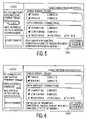
- FIG. 3shows a flowchart of a method for translating a domain name to a corresponding Internet compatible web page address, according to the invention.
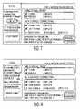
- FIG. 4shows a flowchart of a method for inhibiting and unlocking Internet access using a cable modem, according to the invention.
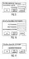
- FIGS. 5-8show web pages generated by the cable modem of FIG. 1 depicting examples of User interface menus providing the capability of locking and unlocking Internet access, according to the invention.
- FIGS. 9-11show User interface menus generated by the cable modem of FIG. 1 exemplifying password and userid entry for use in managing Internet access, according to the invention.
- FIGS. 12 and 13show web pages generated by the cable modem of FIG. 1 , according to the invention.
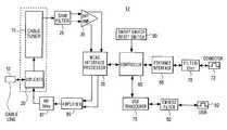
- FIG. 1shows a cable modem system that advantageously prevents unauthorized Internet access by providing a User with the capability of locking and unlocking the modem's Internet communication function.
- the cable modem systemalso incorporates a Domain Name Snoop Server (DNSS) for advantageously intercepting Domain Name resolution requests and for translating a domain name to a corresponding Internet compatible web page address.
- DNSSDomain Name Snoop Server
- the modemadvantageously generates a web page based graphical user interface for display to a user on a PC using different standardized browser applications.
- the exemplary embodiment of system 12 of FIG. 1supports cable modem bridging communication between a remote CATV head-end and local area network (LAN) devices, e.g. a PC, that are local to the cable modem.
- the bi-directional communications between system 12 and the CATV head-endare in a multi-layered protocol format.
- This multi-layered protocol formatinvolves a QAM (Quadrature Amplitude Modulation) or QPSK (Quadrature Phase Shift Keying Modulation) physical layer.
- This physical layerconveys MPEG2 (Moving Pictures Expert Group) transport protocol data conveying DOCSIS MAC (Media Access Control) data frames.
- the MAC dataconveys Ethernet data frames or MAC management data and the Ethernet data in turn conveys IP layer data.
- the cable modemalso maintains a return communication path to the CATV head-end employing Time Division Multiplexed communication of return data in Ethernet protocol.
- the encompassing physical layer data transmitted from the CATV head-end to the cable modemis processed and converted to Ethernet or USB format for communication to LAN devices attached to corresponding Ethernet or USB ports.
- the cable modemmaintains bi-directional communication with the LAN devices and also receives data from the devices in corresponding Ethernet or USB protocol.
- the bi-directional communications between system 12 and the Ethernet compatible or USB compatible devicesinvolve a multi-layered protocol format in similar fashion to the communication between the CATV head-end and system 12 .
- This multi-layered protocol formatmay include Ethernet/USB frames, HTTP (Hyper Text Transmission Protocol) and TCP/IP (Transmission Control Protocol/Internet Protocol) data and other protocols depending on the applications served.
- the cable modem described hereinemploys an MPEG compatible protocol conforming to the MPEG2 image encoding standard, termed the “MPEG standard”.
- This standardis comprised of a system encoding section (ISO/EEC 13818-1, 10 Jun. 1994) and a video encoding section (ISO/IEC 13818-2, 20 Jan. 1995).
- the Internet TCP/IP (Transmission Control Protocol/Internet Protocol) and Ethernet compatible protocols described hereinprovide compatibility with the Multimedia Cable Networks Systems (MCNS) preliminary requirements and DOCSIS 1.0 (Data Over Cable Service Interface Specification 1.0) requirements ratified by the International Telecommunications Union (ITU) March 1998 and as specified in RFC 2669 (Request For Comment Document 2669).
- DOCSIS 1.0Data Over Cable Service Interface Specification 1.0
- web pageis to be interpreted generally to represent any form of data that may be communicated via Internet Protocol (IP) from an Internet source and includes any form of packetized data including streamed video or audio data, telephone messages, computer programs, Emails or other communications, for example.
- IPInternet Protocol
- the cable modem (system 12 ) of FIG. 1communicates with a CATV head-end over a bi-directional broadband high speed RF link on line 10 which typically consists of coaxial cable or hybrid fiber/coax (HFC).
- the modem system 12bi-directionally communicates with devices located at a User site over local area networks (LANs).
- LANslocal area networks
- Typical User-side local area networksinclude Digital/Intel/Xerox Ethernet compatible networks attached via connector 72 .
- Other User-side devicescommunicate via a Universal Serial Bus (USB) compatible network attached via connector 82 .
- User devices attached on the Ethernet and USB networksmay include equipment such as personal computers (PCs), network printers, video receivers, audio receivers, VCRs, DVDs, scanners, copiers, telephones, fax machines and home appliances, for example.
- PCspersonal computers
- PCspersonal computers
- network printersvideo receivers, audio receivers, VCRs, DVDs, scanners, copiers, telephones, fax machines and
- diplexer 20 of cable modem system 12 of FIG. 1separates upstream communications (sent from modem 12 to a CATV head-end) from downstream communications (sent from a CATV head-end to modem 12 ) conveyed via cable line 10 .
- Diplexer 20separates upstream data from downstream data based on the different frequency ranges that the upstream data (typically 5-42 MHz) and downstream data (typically 92-855 MHz) respectively employ.
- Controller 60configures the elements of cable modem 12 of FIG. 1 to receive MPEG2 transport data from the CATV head-end on cable line 10 and to convert the data to Ethernet or USB compatible format for output via ports 72 and 82 respectively. Similarly, controller 60 configures the elements of cable modem 12 of FIG.
- Controller 60configures the elements of system 12 through the setting of control register values within these elements using a bi-directional data and control signal bus. Specifically, controller 60 configures tuner 15 , saw filter 25 , differential amplifier 30 and MCNS (Multimedia Cable Networks Systems) interface device 35 to receive a DOCSIS formatted signal on a previously identified RF channel frequency.
- the DOCSIS formatted signalcomprises an MPEG2 transport protocol format conveying Ethernet compatible data frames including IP data content.
- Controller 60employs an initialization process to determine the RF channel frequency that tuner 15 is to be configured to receive.
- the initialization processinvolves iteratively tuning to successive candidate RF channel frequencies until a DOCSIS compliant signal is obtained.
- Controller 60recognizes a DOCSIS compliant signal on a candidate channel through the successful decode by MCNS interface processor 35 of the received data and through a correspondingly acceptable error rate for the decoded data.
- controller 60 in conjunction with MCNS interface 35 , amplifier 85 and RF transformer 87also transmits data upstream to the CATV head-end for a variety of purposes including for adaptively and iteratively adjusting upstream and downstream communication parameters. These parameters include cable modem transmission power level and timing offset, for example.
- an RF carrieris modulated with MPEG2 transport protocol data using 64 or 256 QAM (Quadrature Amplitude Modulation).
- the MPEG2 transport dataincludes Ethernet formatted data which in turn includes IP data representing a User requested HTML (HyperText Mark-Up Language) web page, for example.
- the MPEG transport datais provided by diplexer 20 to tuner 15 .
- Tuner 15down-converts the input signal from diplexer 20 to a lower frequency band which is filtered by saw filter 25 to enhance signal isolation from neighboring RF channels.
- the filtered signal from unit 25is level shifted and buffered by differential amplifier 30 to provide a signal compatible with MCNS interface processor 35 .
- the resultant down converted, level-shifted signal from amplifier 30is demodulated by MCNS processor 35 .
- This demodulated datais further trellis decoded, mapped into byte aligned data segments, deinterleaved and Reed-Solomon error corrected within processor 35 .
- Trellis decoding, deinterleaving and Reed-Solomon error correctionare known functions described, for example, in the reference text Digital Communication , Lee and Messerschmidt (Kluwer Academic Press, Boston, Mass., USA, 1988).
- Processor 35further converts the MPEG2 format data to Ethernet data frames that are provided to processor 60 .
- Processor 60parses and filters the Ethernet compatible data from unit 35 using filters configured from the CATV head-end.
- the filters implemented by processor 60match IP data identifiers in incoming Ethernet frame packets provided by unit 35 with IP identifier values pre-loaded from the CATV head-end.
- IP identifier valuesare pre-loaded during a previously performed initialization or configuration operation.
- processor 60implements a data admission control function forwarding selected data to local LAN devices and discarding other selected data content.
- This configurable filter systemmay be advantageously used to filter data based on metadata items in the incoming data for a variety of purposes including based on, (a) content rating for parental or other blocking control, (b) predetermined User preferences for targeting advertisements and “push-content”, (c) firewall filtering, (d) identity of source, and (e) a data search function.
- the filtered Ethernet compatible serial datais communicated to a PC via Ethernet interface 65 , filter and isolation transformer 70 and port 72 .
- Interface 65buffers and conditions the data from processor 60 for filtering and transforming by unit 70 for output to a PC via port 72 .
- controller 60converts and filters IP data (conveyed in Ethernet data frames) from processor 35 for output in USB format via port 82 .
- the USB datais buffered by transceiver 75 and filtered by noise and interference suppression (EMI/ESD) filter 80 prior to output to USB compatible LAN devices connected to port 82 .
- EMI/ESDnoise and interference suppression
- Modem system 12also communicates data upstream from an attached PC, for example, to a CATV head-end.
- controller 60 of system 12receives Ethernet compatible data from the attached PC via port 72 , interface 65 and filter/isolation transformer 70 and provides it to processor 35 .
- Processor 35modulates an RF carrier with the received Ethernet format data using 16 QAM or QPSK (Quadrature Phase Shift Keying Modulation).
- the resultant modulated datais time division multiplexed onto cable line 10 for upstream communication via amplifier 85 , transformer 87 and diplexer 20 .
- Amplifier 85outputs the data to the CATV head-end with an appropriate power level selected in the previously described initialization process.
- Transformer 87provides a degree of fault and noise isolation in the event of a failure in the modem 12 or upon the occurrence of locally generated noise in the modem or in attached devices.
- modem system 12also communicates data upstream from devices attached via USB port 82 .
- controller 60 of system 12receives Ethernet compatible data from transceiver 75 and provides it to processor 35 for upstream communication in the manner previously described.
- transceiver 75receives Ethernet data encapsulated within USB frames from port 82 via filter 80 and removes the USB frame data to provide Ethernet format data to controller 60 .
- Controller 60is also responsive to on/off and reset switch 90 and performs a variety of functions in addition to those already described.
- modem 12under the direction of controller 60 advantageously, (a) enables a User to lock the modem and prevent unauthorized Internet access, (b) supports interception of Domain Name resolution requests and the translation of a domain name to a corresponding Internet compatible web page address, (c) enables the allocation of Internet domain names for usage in a home, private Internet or other intra-net system independently of the public Internet, and (d) generates interactive HTML web pages as a graphical User interface.
- controller 60configures modem 12 parameters using configuration information provided from a CATV head-end.
- Controller 60also directs system 12 in synchronizing and multiplexing upstream communication onto cable line 10 and implements a rate limit in controlling upstream data traffic. Further, controller 60 bi-directionally filters received data and provides selected data to either the CATV head-end and LAN devices attached to ports 72 and 82 . Controller 60 also maintains a TCP/IP data stack for buffering and data management purposes and supports data ranging communication with the CATV head-end. The ranging communication is initiated by the CATV head-end and comprises the continuous but intermittent polling of individual modems to determine status and to identify modem or line failures.
- FIG. 2shows a functional depiction of the cable modem of FIG. 1 in a network environment including multiple PCs and a CATV head-end.
- the functional elements of FIG. 2 shown within system 12are executed by controller 60 ( FIG. 1 ) in conjunction with the remaining system 12 elements depicted in FIG. 1 .
- Cable modem 12provides bi-directional bridging communication between a cable service provider 240 at a head-end and LAN connected PCs 220 and 265 .
- bi-directional bridging communication between different input and output protocolsis provided by interface and protocol conversion functions 225 and 235 .
- the bi-directional communication path provided by units 225 and 235supports protocol conversion in a multi-layered protocol structure. As previously described in connection with FIG.
- the protocol layersinvolve hierarchical MPEG2, Ethernet, and IP protocol layers as well as a USB protocol layer and a QAM or QPSK modulation physical layer.
- a TCP/IP stack 260buffers request and response message data for web page generator, server and management function 255 and SNMP (Simple Network Management Protocol) communication function 245 . Further, both the SNMP communication function 245 and the web page manager function 255 employ modem database 250 in responding to commands.
- SNMPSimple Network Management Protocol
- the SNMP function 245receives and interprets SNMP communications from the CATV head-end 240 and manages the operation of system 12 in response to these communications. Specifically, function 245 configures modem 12 and updates system parameters using configuration information provided from the CATV head-end. Function 245 also configures bi-directional filters in system 12 for parsing and either forwarding, re-directing or discarding received messages from PCs 220 , 265 and CATV head-end 240 . Function 245 also supports the previously described ranging communication function initiated by head-end 240 for continuous polling of modem 12 to determine the modem status and operational condition.
- Web page generator function 255generates interactive HTML web pages as exemplified in FIGS. 12 and 13 discussed later.
- the generated web pagescomprise a graphical User interface enabling a technician to readily perform diagnostic tests on system 12 and the associated networks.
- Function 255generates HTML web pages for display on an attached User's PC 220 , for example, allowing a technician to determine faults and status directly through the User's PC.
- a generated web pagemay also be remotely accessed following a password and userid authorization procedure with a remote PC using SNMP or another protocol.
- the generated web pagesenable an authorized User to prevent unauthorized Internet access by providing a User with the capability of locking and unlocking the modem's Internet communication function.
- the generated web pagesalso provide a User interface enabling viewing and/or update of system parameters and received data such as security alerts, special events (promotions etc.), network traffic statistics and underflow or overflow conditions and data transfer statistics.
- the web pagesalso provide diagnostic, billing, status, internal configuration and other information and enable modem configuration change.
- the functions performed by the generated web pages that are described hereinmay be incorporated within a web browser page.
- the web pages generated by function 255also provide an interface enabling a User to allocate an Internet domain name to a private Internet (versus the public Internet).
- the interfacefor example, enables a User to allocate an Internet domain name to an element in a home (or other) intra-net system.
- an intercepting Domain Name Snoop Server (DNSS) 230supports interception of Domain Name resolution requests generated by PC 220 in response to a User Internet web page request initiated via a browser running on PC 220 , for example.
- the DNSS 230translates the intercepted domain name to a corresponding private Internet web page address thereby enabling private Internet domain names to be allocated via the generated web pages for usage in a home or other private Internet or intra-net system and independently of the public Internet.
- FIG. 3shows a flowchart of a method for translating a domain name to a corresponding Internet compatible web page address.
- the methodis employed by controller 60 of FIG. 1 (in conjunction with the other elements of system 12 of FIGS. 1 and 2 ) to enable private Internet domain names to be allocated via a generated web page for usage in a home or other private intra-net system.
- PC 220FIG. 2
- step 303FIG. 3
- the PC 220 browsersubmits a Domain Name Request following standard Internet resolution protocols as detailed the RFC (Request For Comment) documents available on the Internet e.g. RFC 1035, 1591, 1816 as well as subsequent and earlier RFCs associated with these documents.
- RFCRequest For Comment
- DNSDomain Name Server
- Requestsare submitted by a resolver to one or more DNS's to get the full IP address of a particular machine or device. For example, on a web browser a User may type RCA.com. This is then sent to a DNS which may translate it to IP address 157.254.235.215. A web browser uses this IP address to contact the web server and retrieve web page information. Note that this example is extremely simplified. In practice, several hierarchically organized DNS's are used via a referral or recursion process, plus many other processes are involved including caching and age factor processing.
- the Domain Name Resolution requestis submitted by PC 220 to system 12 for forwarding and translation of the Domain Name entered by the User into a corresponding IP address of the source of the requested web page.
- an Intercepting Domain Name database(unit 250 of FIG. 2 ) is provided for use within system 12 .
- the intercepting Domain Name databaseassociates IP addresses with Domain Names of intra-net devices on a domestic LAN (a private intra-net) and is derived from Domain Names and IP address information locally allocated by a User via a web page interface generated by system 12 .
- the intercepting Domain Name databasemay be downloaded using DHCP (Dynamic Host Configuration Protocol) from a remote Internet location e.g. from the CATV head-end.
- the intercepting Domain Name databasemay be downloaded from local Internet location e.g. from local storage or the database may be pre-stored within system 12 .
- step 310Snoop Server (DNSS) 230 of system 12 ( FIG. 2 ) examines the Domain Name Resolution request message from PC 220 to determine if the conveyed Domain Name matches a name in database 250 .
- step 315system 12 (under direction of controller 60 of FIG. 1 ) intercepts the Domain Name Resolution request from PC 220 ( FIG. 2 ) if the conveyed Domain Name matches a name in database 250 ( FIG. 2 ). Upon such a name match, system 12 , in step 317 , inhibits further communication of the Domain Name Resolution message to a public Internet Domain Name Server.
- Snoop Server (DNSS) 230 in step 320in conjunction with database 250 , translates the intercepted Domain Name to an IP compatible address and in step 323 communicates the IP address back to the requesting source (PC 220 in this example). Further, system 12 in step 325 maintains a history of Domain Name and IP address translations and requests within database 250 and collates and compiles the information for monitoring and other purposes including, for example, parental control, firewall filtering, or for the accumulation of User preference data as a background operation. The compiled information is made available for display on a web page generated by unit 255 either continuously or upon User request via the web page. The process of FIG. 3 terminates in step 330 .
- step 317is not performed and system 12 also communicates the Domain Name Resolution message received from PC 220 to a public Internet Domain Name Server.
- system 12may receive two IP address translations in response. One from DNSS 230 and one from a remote public Domain Name Server. The received IP addresses may or may not be the same, consequently, a potential address conflict and race condition arises.
- system 12is programmed to select the first IP address response received. The first response received is typically the response from local DNSS 230 .
- system 12may be conditioned differently, for example, system 12 may be conditioned to give priority to responses from a particular source such as from the remote server.
- the intercepting Domain Name Server and the features of the process of FIG. 3provide a means for a User to easily and quickly allocate, add, or alter Internet domain names used in a private Internet, e.g., to accommodate the addition of devices to the private Internet.
- Thisenables a User to flexibly manage and change the configuration of elements and peripherals of a home (or other) intra-net system via a web page running on a standardized browser, for example.
- a Usermay advantageously manage Domain Name allocation on a private Internet without impact on the public Internet or the cumbersome and time consuming burden of having to register Domain Name allocations and changes with public Internet gateways and service providers (ISPs).
- ISPspublic Internet gateways and service providers
- a User requesting a web page generated within the private Internetneed not know the complex IP address of this web page. Instead the User may access the web page by submitting a locally allocated private Internet Domain Name that is recognized by the Intercepting Domain Name Server as corresponding to the required web page.
- the intercepting Domain Name Server and the features of the process of FIG. 3also advantageously enable: (a) the IP addresses of the web pages generated by system 12 or of other information sources or devices on a private Internet to be dynamically assigned for security or other purposes; (b) the assignment of alias (or User customizable) Domain Names and IP addresses to an information source enabling system 12 (or a DNS server) to intercept and respond to DNS requests that are not directly addressed to it, for example; and (c) the overriding of a Domain Name with a locally allocated substitute name.
- system 12is able to communicate to a device on a LAN or subnet using a locally assigned private Internet domain name or IP address identifying the device as being on this particular LAN or subnet.
- the domain name or IP addressmay be assigned via a web page generated by unit 255 or may be assigned by the local or remote downloading of data to database 250 ( FIG. 2 ) as previously mentioned. This eliminates the need for a User to have to adjust the IP address or netmask of a PC on the LAN in order to access the web page generated by unit 255 in system 12 , for example.
- FIG. 4shows a flowchart of a method for inhibiting and unlocking Internet access using a cable modem.
- the User interfaceis presented on a PC attached to Ethernet port 72 .
- the methodis employed by controller 60 of FIG. 1 (in conjunction with the other elements of system 12 of FIGS. 1 and 2 ) to enable secure locking of the modem to prevent unauthorized Internet access. This ensures that unauthorized users (e.g., children) will not have access to the network devices unattended. It also provides assurance to a User that his/her PC cannot be accessed while the modem is locked.
- step 405 of FIG. 4following the start at step 400 , the communication bridging capability of cable modem 12 is enabled.
- this bridging capabilityenables an Ethernet device, e.g. a PC connected to port 72 of system 12 of FIG. 1 , to connect to an RF network for communication on cable line 10 as specified under DOCSCIS standards.
- the DOCSIS specificationsprovide that a modem shall consistently range (i.e. maintain bi-directional communication) with the Cable Modem Termination System (CMTS) while connected. Therefore, in order to remove Internet connectivity, the consumer either needs to physically disconnect the modem from the RF network, or needs to remove power to the modem.
- CMTSCable Modem Termination System
- steps 410 and 415 of FIG. 4The authorization of a User to initiate locking of the modem is verified in steps 410 and 415 of FIG. 4 .
- a userid and password entered in step 410is verified in step 415 using a menu exemplified in FIG. 9 .
- This menu and other menus used in the FIG. 4 processare displayed on a PC attached to port 72 ( FIG. 1 ).
- the entry of an incorrect password or useridresults in steps 410 and 415 being repeated for a specified number of attempts using the incorrect password processing menu of FIG. 11 until controller 60 ( FIG. 1 ) declares successful verification or failure.
- the password for the modemis changed using a change password menu as exemplified in FIG. 10 .
- This menumay be invoked via icons 505 and 605 in the exemplary modem generated web pages of FIGS. 5 and 6 respectively.
- the password change menu of FIG. 10prompts the User for the original password and the new password twice (as confirmation of the new password).
- a typical passwordmay be, for example, any combination of letters, numbers, and non-alphanumeric characters up to a maximum of 10 characters.
- the menu of FIG. 10 or a similar menumay be used to initially set the password upon initialization of modem 12 .
- MIBManagement Information Base comprising a software procedure allowing remote management
- a default password(e.g., “letmeout”), detailed in the User's manual, may be used to invoke the procedure for allowing a head-end to reset the password.
- a private MIB enabled in the modemallows a management station, operated from the cable head-end, or the network operations center controlled by an Internet service provider, to reset the password back to the default, in the event that a password is lost or forgotten.
- an SNMP manager at the head-end, or the Network Operations Centercommands the MIB to reset either the User's password or userid or both password and userid.
- a Usertelephones the cable operator or Network Operations Center and provides the default password as authorization to request that the password in his modem be reset.
- the default passwordmay be communicated to the head-end via modem 12 to directly invoke the MIB based procedure to reset the password.
- a Userrequests display of a web page in step 420 .
- the requested web pageacts as the User interface permitting the User to lock the modem and inhibit Internet access communication.
- a Userinitiates locking and unlocking of Internet access communication of the modem in step 425 via icons 500 and 700 of the web pages of FIGS. 5 and 7 respectively.
- a Userinitiates unlocking and locking of Internet access communication via check boxes 600 and 800 of the web pages of FIGS. 6 and 8 respectively.
- a Userinitiates locking of the modem in step 425 via icon 500 of the web page of FIG. 5 or via a check box (e.g. as shown in icon 800 of the web page of FIG. 8 ).
- the functions describedmay be activated and inactivated using User interface menus and web pages that differ from those depicted in FIGS. 5-12 .
- Modem 12Internet access communication is disabled in step 430 and a web page is displayed indicating this disabled status in the manner exemplified by icons 500 and 800 of FIGS. 5 and 8 respectively.
- Modem 12disables Internet access by advantageously inhibiting bridging communication of IP data between the CATV head-end and the LAN devices connected to ports 72 and 82 .
- any attempt to access the Internet that is originated by a web browser on a client devicee.g. PC 220 of FIG. 2
- modem 12While the modem is locked, no traffic is passed from the customer's home network, or PC (and private Internet), to the RF side of the network to the head-end and the public Internet.
- the bridging function of the modemis disabled.
- modem 12maintains multi-layered protocol communication with the CATV head-end to support the DOCSIS standard ranging process and to support SNMP (simple network management protocol as defined in RFC 1157) access to the database (unit 250 of FIG. 2 ) within modem 12 .
- the ranging communication processis initiated by the CATV head-end and is described in the DOCSIS Radio Frequency Interface Specification.
- the ranging communication messagescomprise periodic ranging maintenance messages that are conveyed on the MAC (Media Access Control) layer of the OSI (Open Systems Interconnection) network model.
- the database communicationinvolves SNMP which involves User Datagram Protocol (UDP) operating on IP at the session layer of the OSI model.
- UDPUser Datagram Protocol
- modem 12In the locked mode, modem 12 also maintains multi-layered protocol communication with a PC (e.g. PC 220 of FIG. 2 attached to an Ethernet port) to provide a web page based User interface (as exemplified in FIGS. 5-8 ) allowing a User to unlock and re-lock the modem as required.
- a PCe.g. PC 220 of FIG. 2 attached to an Ethernet port
- Modem 12disables Internet access by advantageously inhibiting bridging communication of IP data between the CATV head-end and attached LAN devices using a filter mechanism.
- a filter mechanismmay be employed to pass data between the CATV head-end and attached LAN devices in one or more particular protocol layers whilst inhibiting communication in other protocol layers.
- the use of bi-directional filteringpermits particular protocol layers to be passed in one direction, e.g. from head-end to a LAN device, whilst one or more different layers are passed from a LAN device to the head-end. Alternatively, all bridging communication may be inhibited.
- the filtermay be implemented as a configurable filter and used to bi-directionally filter data between the CATV head-end and attached LAN devices based on one or more of, (a) content, (b) protocol type and (c) data source or destination.
- the content filteringmay be implemented based on metadata or other content or content derived items for a variety of specific purposes including those previously described in connection with FIG. 1 .
- the filtermay be implemented in similar fashion to the DOCSIS Cable Device MIB as specified in RFC 2669 which defines the docsdevFilterIPDirection object and the docsDevFilterIPDaddr object or may be implemented using other filter mechanisms.
- a filter using primarily these two objectsmay be employed to restrict all traffic, or selected traffic, from a User's web browser (e.g. on PC 220 of FIG. 2 ) to the head-end and further to the Internet.
- the modemfilters data traffic to restrict all inbound traffic from the browser (e.g. in PC 220 ) with a destination address matching the gateway IP address (corresponding to the IP address of the Cable Modem Termination System in the head-end).
- such a filtermay be configured to restrict any selected protocol or selected content being passed in either direction through the modem. This ensures that a User may block access to the Internet and also that access is blocked from the Internet (via the head-end) to the User's PC to enhance security.
- modem 12prevents unauthorized Internet access by inhibiting communication to the CATV head-end on the Ethernet communication protocol layer whilst concurrently maintaining communication to the CATV head-end on the MAC protocol layer.
- the MAC protocol layerconveys management information supporting ranging operation and other modem and network management functions.
- modem 12concurrently maintains multi-layered protocol communication with a PC (e.g. PC 220 of FIG. 2 attached to an Ethernet port of modem 12 ) to provide a web page based User interface (as exemplified in FIGS. 5-8 ) allowing a User to unlock and re-lock the modem as required.
- PCe.g. PC 220 of FIG. 2 attached to an Ethernet port of modem 12
- any attempt by an unauthorized User, e.g., in step 445 , to surf the webis blocked and results in termination of this branch of the process of FIG. 4 in step 450 .
- the modemmay be unlocked by an authorized User in steps 440 , 455 and 460 .
- a password prompt menu(e.g. the menu of FIG. 9 ) is displayed in response to a User's attempt to unlock the modem in step 440 .
- a Usermay attempt to unlock the modem by either activating unlock button 700 of the web page of FIG. 7 or checking the “Web Access” checkbox 800 of FIG. 8 for example.
- step 460Upon validation of a correct password in step 460 , following password entry in step 455 , the modem is unlocked to support bridging communication in step 470 and to provide the User with Internet access. This branch of the FIG. 4 process terminates in step 475 .
- the UserUpon identification of an invalid password in step 460 , the User is notified that the entered password is invalid in step 465 via a menu as exemplified by FIG. 11 . Through this menu, the User in step 465 may retry password validation starting with step 440 or the User may cancel the attempt to unlock the modem. If the User cancels his unlocking attempt in step 465 the processed is returned to step 430 and a web page is displayed.
- the authorization of a User to lock and unlock the modem to provide Internet accessmay be performed in other ways and need not involve the entry of a password or userid.
- An access card mechanismmay be provided within modem 12 for use in validating authorization based on a digital signature, or other authorization or entitlement data, for example.
- modem 12may respond to a different access device such as a physical or electronic key for determining User authorization.
- FIGS. 12 and 13show web pages generated by the cable modem of FIG. 1 . These web pages advantageously enable a technician, for example, to determine and adjust specific internal modem configurations.
- the web pagessupport interactive functions comprising one or more of, (a) configuring modem 12 , (b) requesting display of system parameters, (c) selecting a service billing option, and (d) assigning Internet addresses.
- the web pageemploys password protection access similar to that previously described in connection with preventing unauthorized Internet access. Consequently, even if an unauthorized User discovers the URL address of a particular web page, it is password protected.
- the web pagealso displays specific diagnostic information to a technician thereby eliminating the need for the technician to rely on LED indications and special diagnostic equipment to be able to access internal status (e.g.
- a technicianmay set return channel power level (item 913 of FIG. 12 ), for example.
- the information available on the web pageincludes specific information about the customer's network configuration. Specifically, it includes the number of PCs connected to the network, the Ethernet speed (100 Mb or 10 Mb) and the MAC address of modem 12 (items 900 and 902 of FIG. 13 ), for example.
- the displayed web pagemay indicate other address information such as (a) the web page IP address, (b) a File Transfer Protocol (FTP) address, and (c) an Email address.
- the web pagealso provides other customer network information including the amount of traffic and details concerning collisions on the network. This advantageously eliminates the need for customized diagnostic equipment or software.
- Modem 12also generates browser alert boxes for certain network events of which a User would like to be informed. Further, the browser allows special HTML information to be displayed during a retrieval of web page data. During this time period modem 12 sends information to a user concerning certain events occurring on the network. These events include alerts about unauthorized access to the User's LAN network, LAN network traffic overflow, and data transfer amounts through modem 12 . Modem 12 also allows a cable Internet service provider to limit data transfer by establishing quotas and the User is also able to see the amount of data transferred. The alert boxes also allows a User to view statistics for specific types of accesses including web page retrievals, DNS requests, FTP (File Transfer Protocol) file transfers, email messages, etc.
- FTPFile Transfer Protocol
- these events and associated informationare not confined to being displayed in alert boxes on a browser but are also available on a web page generated by modem 12 in response to an on-demand User information retrieval request.
- the information items previously mentioned in connection with FIGS. 12 and 13may be displayed in areas 905 and 907 of FIGS. 12 and 13 , for example, or may be presented in another display format.
- command line 911 in FIGS. 12 and 13may be used for entry and allocation of a domain name or IP address to a peripheral (locally connected) device of modem 12 .
- Command line 911may also be used in associating an entered domain name with a corresponding IP address (and vice versa) involving the update of a database within modem 12 .
- a peripheral devicemay comprise, (a) a device on an intra-net and (b) a device on a domestic home network, and (c) a device on a private Internet.
- command line 911provides a data entry line enabling User entry of data for configuration of a data traffic filter within modem 12 .
- Such a traffic filtermay be used for filtering data based on, (a) content rating for parental or other blocking control, (b) predetermined User preferences for targeting advertisements and “push-content”, (c) firewall filtering, (d) identity of source or destination, and (e) a data search function.
- the web pages of FIGS. 12 and 13may employ menus displayed in areas 905 and 907 , for example, specifically supporting the entry, allocation and association of domain names and corresponding IP addresses.
- specific menus presented in areas 905 and 907may also be used for activating, inactivating and configuring data traffic filters.
- Modem 12also acts as a browser proxy agent for web page surfing. This increases a browser's speed of surfing the web, especially if there is more than one browser active at the same time (i.e. more than 1 PC on a customer's LAN network). Modem 12 pre-fetches and forward caches web pages associated with the web page that a user is currently viewing. This increases Internet surfing speeds by eliminating the delay caused by a remote web site or the Internet infrastructure. In addition, by configuring the internal filters previously described in connection with FIG. 4 , modem 12 is used as a firewall excluding disruptive and objectionable traffic to protect a User's network system in a home or business from outside invasion and disruption.
- the architectures of the systems of FIG. 1 and FIG. 2is not exclusive. Other architectures may be derived in accordance with the principles of the invention to accomplish the same objectives. Further, the functions of the elements of modem 12 of FIGS. 1 and 2 and the process steps of FIGS. 3 and 4 may be implemented in whole or in part within the programmed instructions of controller 60 . In addition, the principles of the invention apply to any multi-layered protocol bi-directional communication system and are not limited to DOCSIS compatible modems or to any other type of modem.
Landscapes
- Engineering & Computer Science (AREA)
- Computer Networks & Wireless Communication (AREA)
- Signal Processing (AREA)
- Theoretical Computer Science (AREA)
- Computer Hardware Design (AREA)
- Physics & Mathematics (AREA)
- General Engineering & Computer Science (AREA)
- General Physics & Mathematics (AREA)
- Small-Scale Networks (AREA)
- Data Exchanges In Wide-Area Networks (AREA)
- Computer And Data Communications (AREA)
Abstract
Description
Claims (16)
Priority Applications (12)
| Application Number | Priority Date | Filing Date | Title |
|---|---|---|---|
| US09/567,398US7574494B1 (en) | 1999-10-15 | 2000-05-09 | User interface for a bi-directional communication system |
| EP00970857AEP1224542B1 (en) | 1999-10-15 | 2000-10-13 | A user interface for a bi-directional communication system |
| AU80176/00AAU8017600A (en) | 1999-10-15 | 2000-10-13 | A user interface for a bi-directional communication system |
| PCT/US2000/028298WO2001029658A2 (en) | 1999-10-15 | 2000-10-13 | A user interface for a bi-directional communication system |
| JP2001532387AJP4502563B2 (en) | 1999-10-15 | 2000-10-13 | User interface for two-way communication system |
| BR0014774-5ABR0014774A (en) | 1999-10-15 | 2000-10-13 | User interface for a two-way communication system |
| MXPA02003710AMXPA02003710A (en) | 1999-10-15 | 2000-10-13 | A user interface for a bi-directional communication system. |
| KR1020027004575AKR100750611B1 (en) | 1999-10-15 | 2000-10-13 | User Interface for Bidirectional Communication Systems |
| DE60011121TDE60011121T2 (en) | 1999-10-15 | 2000-10-13 | USER INTERFACE FOR A TWO-WAY COMMUNICATION SYSTEM |
| CNB008142890ACN1197000C (en) | 1999-10-15 | 2000-10-13 | User interface for two-way communication system |
| ES00970857TES2220550T3 (en) | 1999-10-15 | 2000-10-13 | USER INTERFACE FOR A BIDIRECTIONAL COMMUNICATION SYSTEM. |
| MYPI20004828AMY123698A (en) | 1999-10-15 | 2000-10-14 | A user interface for a bi-directional communication system |
Applications Claiming Priority (2)
| Application Number | Priority Date | Filing Date | Title |
|---|---|---|---|
| US15978899P | 1999-10-15 | 1999-10-15 | |
| US09/567,398US7574494B1 (en) | 1999-10-15 | 2000-05-09 | User interface for a bi-directional communication system |
Publications (1)
| Publication Number | Publication Date |
|---|---|
| US7574494B1true US7574494B1 (en) | 2009-08-11 |
Family
ID=40934389
Family Applications (1)
| Application Number | Title | Priority Date | Filing Date |
|---|---|---|---|
| US09/567,398Expired - Fee RelatedUS7574494B1 (en) | 1999-10-15 | 2000-05-09 | User interface for a bi-directional communication system |
Country Status (3)
| Country | Link |
|---|---|
| US (1) | US7574494B1 (en) |
| KR (1) | KR100750611B1 (en) |
| MY (1) | MY123698A (en) |
Cited By (59)
| Publication number | Priority date | Publication date | Assignee | Title |
|---|---|---|---|---|
| US20050015453A1 (en)* | 2003-05-28 | 2005-01-20 | Lucent Technologies Inc. | Method and system for internet censorship |
| US20050055426A1 (en)* | 2000-06-12 | 2005-03-10 | Kim Smith | System, method and computer program product that pre-caches content to provide timely information to a user |
| US20070055913A1 (en)* | 2005-09-08 | 2007-03-08 | International Business Machines Corporation | Facilitating detection of hardware service actions |
| US20070117018A1 (en)* | 2005-11-22 | 2007-05-24 | Huggins Robert A | Silicon and/or boron-based positive electrode |
| US20080120508A1 (en)* | 2006-11-20 | 2008-05-22 | Utstarcom, Inc. | Method and Apparatus for Facilitating the Resetting of a Presently Used Password |
| US20080208785A1 (en)* | 2006-03-30 | 2008-08-28 | Pegasystems, Inc. | User interface methods and apparatus for rules processing |
| US20090113045A1 (en)* | 2007-10-30 | 2009-04-30 | Embarq Holdings Company, Llc | System and method for an integrated DSL/cable modem performance test |
| US20090217097A1 (en)* | 2008-02-25 | 2009-08-27 | At&T Knowledge Ventures, L.P. | Portal facilitating telecommunication installation and repair services |
| US20100253841A1 (en)* | 2006-11-07 | 2010-10-07 | Sony Corporation | Communication system, transmitter, receiver, communication method, program, and communication cable |
| US20110187928A1 (en)* | 2010-02-04 | 2011-08-04 | Eldon Technology Limited | Electronic appliance status notification via a home entertainment system |
| US20110271149A1 (en)* | 2010-04-28 | 2011-11-03 | Microsoft Corporation | Diagnostic dashboard for web pages |
| EP2487874A1 (en)* | 2011-02-12 | 2012-08-15 | Huawei Device Co., Ltd. | Mobile broadband device and method for manageing mobile broadband device |
| US8250525B2 (en) | 2007-03-02 | 2012-08-21 | Pegasystems Inc. | Proactive performance management for multi-user enterprise software systems |
| US8335704B2 (en) | 2005-01-28 | 2012-12-18 | Pegasystems Inc. | Methods and apparatus for work management and routing |
| US8369344B1 (en)* | 2009-03-18 | 2013-02-05 | Extreme Networks, Inc. | Customer isolation using a common forwarding database with hardware learning support |
| US8479157B2 (en) | 2004-05-26 | 2013-07-02 | Pegasystems Inc. | Methods and apparatus for integration of declarative rule-based processing with procedural programming in a digital data-processing evironment |
| US20130179969A1 (en)* | 2000-06-23 | 2013-07-11 | Peder J. Jungck | Apparatus and Method for Domain Name Resolution |
| US20130305298A1 (en)* | 2007-06-26 | 2013-11-14 | Sony Corporation | Communication system, transmitter, receiver, communication method, program, and communication cable |
| US20140219166A1 (en)* | 2013-02-01 | 2014-08-07 | Kabushiki Kaisha Toshiba | Received data processing apparatus and method of processing the same |
| US8880487B1 (en) | 2011-02-18 | 2014-11-04 | Pegasystems Inc. | Systems and methods for distributed rules processing |
| US8898709B2 (en) | 2010-02-04 | 2014-11-25 | Eldon Technology Limited | Apparatus for displaying electrical device usage information on a television receiver |
| US8924335B1 (en) | 2006-03-30 | 2014-12-30 | Pegasystems Inc. | Rule-based user interface conformance methods |
| US20150234839A1 (en)* | 2008-02-25 | 2015-08-20 | Audience Partners, Llc | Systems and methods for dynamically embedding a creative data file within a web page |
| US9195936B1 (en) | 2011-12-30 | 2015-11-24 | Pegasystems Inc. | System and method for updating or modifying an application without manual coding |
| US9495860B2 (en) | 2013-12-11 | 2016-11-15 | Echostar Technologies L.L.C. | False alarm identification |
| US9511259B2 (en) | 2014-10-30 | 2016-12-06 | Echostar Uk Holdings Limited | Fitness overlay and incorporation for home automation system |
| US9537824B2 (en) | 2000-06-23 | 2017-01-03 | Cloudshield Technologies, Inc. | Transparent provisioning of network access to an application |
| US9621959B2 (en) | 2014-08-27 | 2017-04-11 | Echostar Uk Holdings Limited | In-residence track and alert |
| US9628286B1 (en) | 2016-02-23 | 2017-04-18 | Echostar Technologies L.L.C. | Television receiver and home automation system and methods to associate data with nearby people |
| US9632746B2 (en) | 2015-05-18 | 2017-04-25 | Echostar Technologies L.L.C. | Automatic muting |
| US9678719B1 (en) | 2009-03-30 | 2017-06-13 | Pegasystems Inc. | System and software for creation and modification of software |
| US9723393B2 (en) | 2014-03-28 | 2017-08-01 | Echostar Technologies L.L.C. | Methods to conserve remote batteries |
| US9729989B2 (en) | 2015-03-27 | 2017-08-08 | Echostar Technologies L.L.C. | Home automation sound detection and positioning |
| US9769522B2 (en) | 2013-12-16 | 2017-09-19 | Echostar Technologies L.L.C. | Methods and systems for location specific operations |
| US9772612B2 (en) | 2013-12-11 | 2017-09-26 | Echostar Technologies International Corporation | Home monitoring and control |
| US9798309B2 (en) | 2015-12-18 | 2017-10-24 | Echostar Technologies International Corporation | Home automation control based on individual profiling using audio sensor data |
| US9824578B2 (en) | 2014-09-03 | 2017-11-21 | Echostar Technologies International Corporation | Home automation control using context sensitive menus |
| US9838736B2 (en) | 2013-12-11 | 2017-12-05 | Echostar Technologies International Corporation | Home automation bubble architecture |
| US9882736B2 (en) | 2016-06-09 | 2018-01-30 | Echostar Technologies International Corporation | Remote sound generation for a home automation system |
| US9948477B2 (en) | 2015-05-12 | 2018-04-17 | Echostar Technologies International Corporation | Home automation weather detection |
| US9946857B2 (en) | 2015-05-12 | 2018-04-17 | Echostar Technologies International Corporation | Restricted access for home automation system |
| US9960980B2 (en) | 2015-08-21 | 2018-05-01 | Echostar Technologies International Corporation | Location monitor and device cloning |
| US9967614B2 (en) | 2014-12-29 | 2018-05-08 | Echostar Technologies International Corporation | Alert suspension for home automation system |
| US9983011B2 (en) | 2014-10-30 | 2018-05-29 | Echostar Technologies International Corporation | Mapping and facilitating evacuation routes in emergency situations |
| US9989507B2 (en) | 2014-09-25 | 2018-06-05 | Echostar Technologies International Corporation | Detection and prevention of toxic gas |
| US9996066B2 (en) | 2015-11-25 | 2018-06-12 | Echostar Technologies International Corporation | System and method for HVAC health monitoring using a television receiver |
| US10049515B2 (en) | 2016-08-24 | 2018-08-14 | Echostar Technologies International Corporation | Trusted user identification and management for home automation systems |
| US10060644B2 (en) | 2015-12-31 | 2018-08-28 | Echostar Technologies International Corporation | Methods and systems for control of home automation activity based on user preferences |
| US10073428B2 (en) | 2015-12-31 | 2018-09-11 | Echostar Technologies International Corporation | Methods and systems for control of home automation activity based on user characteristics |
| US10091017B2 (en) | 2015-12-30 | 2018-10-02 | Echostar Technologies International Corporation | Personalized home automation control based on individualized profiling |
| US10101717B2 (en) | 2015-12-15 | 2018-10-16 | Echostar Technologies International Corporation | Home automation data storage system and methods |
| US10294600B2 (en) | 2016-08-05 | 2019-05-21 | Echostar Technologies International Corporation | Remote detection of washer/dryer operation/fault condition |
| US10348682B2 (en)* | 2014-05-12 | 2019-07-09 | Michael C. Wood | Transparent traffic control device and method |
| US10469396B2 (en) | 2014-10-10 | 2019-11-05 | Pegasystems, Inc. | Event processing with enhanced throughput |
| US10467200B1 (en) | 2009-03-12 | 2019-11-05 | Pegasystems, Inc. | Techniques for dynamic data processing |
| US10698599B2 (en) | 2016-06-03 | 2020-06-30 | Pegasystems, Inc. | Connecting graphical shapes using gestures |
| US10698647B2 (en) | 2016-07-11 | 2020-06-30 | Pegasystems Inc. | Selective sharing for collaborative application usage |
| US11048488B2 (en) | 2018-08-14 | 2021-06-29 | Pegasystems, Inc. | Software code optimizer and method |
| US11567945B1 (en) | 2020-08-27 | 2023-01-31 | Pegasystems Inc. | Customized digital content generation systems and methods |
Families Citing this family (1)
| Publication number | Priority date | Publication date | Assignee | Title |
|---|---|---|---|---|
| US8601052B2 (en) | 2010-10-04 | 2013-12-03 | Qualcomm Incorporated | System and method of performing domain name server pre-fetching |
Citations (23)
| Publication number | Priority date | Publication date | Assignee | Title |
|---|---|---|---|---|
| US5471190A (en)* | 1989-07-20 | 1995-11-28 | Timothy D. Schoechle | Method and apparatus for resource allocation in a communication network system |
| US5699532A (en)* | 1994-06-01 | 1997-12-16 | International Business Machines Corporation | Dynamic multipath channel interface for input/output channels |
| US5734831A (en)* | 1996-04-26 | 1998-03-31 | Sun Microsystems, Inc. | System for configuring and remotely administering a unix computer over a network |
| US5790548A (en) | 1996-04-18 | 1998-08-04 | Bell Atlantic Network Services, Inc. | Universal access multimedia data network |
| FR2760159A1 (en) | 1997-02-21 | 1998-08-28 | Netgem | METHOD FOR LIMITING THE POSSIBILITIES OF ACCESS AND NAVIGATION OF AN INTERNET TERMINAL |
| US5809252A (en) | 1996-12-13 | 1998-09-15 | Intel Corporation | Cable modem interface unit for capturing and processing incoming packets from a cable modem |
| US5887139A (en) | 1996-08-19 | 1999-03-23 | 3Com Corporation | Configurable graphical user interface useful in managing devices connected to a network |
| US5892917A (en)* | 1995-09-27 | 1999-04-06 | Microsoft Corporation | System for log record and log expansion with inserted log records representing object request for specified object corresponding to cached object copies |
| GB2333670A (en) | 1998-01-19 | 1999-07-28 | Ericsson Telefon Ab L M | Address allocation |
| US5956484A (en)* | 1995-12-13 | 1999-09-21 | Immersion Corporation | Method and apparatus for providing force feedback over a computer network |
| US5961604A (en) | 1997-06-03 | 1999-10-05 | Alpha Technologies, Inc. | Status monitoring systems for cable television signal distribution networks |
| US5983214A (en)* | 1996-04-04 | 1999-11-09 | Lycos, Inc. | System and method employing individual user content-based data and user collaborative feedback data to evaluate the content of an information entity in a large information communication network |
| US6006265A (en) | 1998-04-02 | 1999-12-21 | Hotv, Inc. | Hyperlinks resolution at and by a special network server in order to enable diverse sophisticated hyperlinking upon a digital network |
| US6012088A (en) | 1996-12-10 | 2000-01-04 | International Business Machines Corporation | Automatic configuration for internet access device |
| US6012100A (en)* | 1997-07-14 | 2000-01-04 | Freegate Corporation | System and method of configuring a remotely managed secure network interface |
| US6023724A (en)* | 1997-09-26 | 2000-02-08 | 3Com Corporation | Apparatus and methods for use therein for an ISDN LAN modem that displays fault information to local hosts through interception of host DNS request messages |
| US6125385A (en)* | 1996-08-01 | 2000-09-26 | Immersion Corporation | Force feedback implementation in web pages |
| US6266664B1 (en)* | 1997-10-01 | 2001-07-24 | Rulespace, Inc. | Method for scanning, analyzing and rating digital information content |
| US6304909B1 (en)* | 1998-12-18 | 2001-10-16 | International Business Machines Corporation | Client-controlled link processing in computer network |
| US6308205B1 (en)* | 1998-10-22 | 2001-10-23 | Canon Kabushiki Kaisha | Browser-based network management allowing administrators to use web browser on user's workstation to view and update configuration of network devices |
| US6381638B1 (en)* | 1999-02-24 | 2002-04-30 | 3Com Corporation | System and method for options based address reuse |
| US7139811B2 (en)* | 2001-08-01 | 2006-11-21 | Actona Technologies Ltd. | Double-proxy remote data access system |
| US7254642B2 (en)* | 2003-01-30 | 2007-08-07 | International Business Machines Corporation | Method and apparatus for local IP address translation |
- 2000
- 2000-05-09USUS09/567,398patent/US7574494B1/ennot_activeExpired - Fee Related
- 2000-10-13KRKR1020027004575Apatent/KR100750611B1/ennot_activeExpired - Fee Related
- 2000-10-14MYMYPI20004828Apatent/MY123698A/enunknown
Patent Citations (23)
| Publication number | Priority date | Publication date | Assignee | Title |
|---|---|---|---|---|
| US5471190A (en)* | 1989-07-20 | 1995-11-28 | Timothy D. Schoechle | Method and apparatus for resource allocation in a communication network system |
| US5699532A (en)* | 1994-06-01 | 1997-12-16 | International Business Machines Corporation | Dynamic multipath channel interface for input/output channels |
| US5892917A (en)* | 1995-09-27 | 1999-04-06 | Microsoft Corporation | System for log record and log expansion with inserted log records representing object request for specified object corresponding to cached object copies |
| US5956484A (en)* | 1995-12-13 | 1999-09-21 | Immersion Corporation | Method and apparatus for providing force feedback over a computer network |
| US5983214A (en)* | 1996-04-04 | 1999-11-09 | Lycos, Inc. | System and method employing individual user content-based data and user collaborative feedback data to evaluate the content of an information entity in a large information communication network |
| US5790548A (en) | 1996-04-18 | 1998-08-04 | Bell Atlantic Network Services, Inc. | Universal access multimedia data network |
| US5734831A (en)* | 1996-04-26 | 1998-03-31 | Sun Microsystems, Inc. | System for configuring and remotely administering a unix computer over a network |
| US6125385A (en)* | 1996-08-01 | 2000-09-26 | Immersion Corporation | Force feedback implementation in web pages |
| US5887139A (en) | 1996-08-19 | 1999-03-23 | 3Com Corporation | Configurable graphical user interface useful in managing devices connected to a network |
| US6012088A (en) | 1996-12-10 | 2000-01-04 | International Business Machines Corporation | Automatic configuration for internet access device |
| US5809252A (en) | 1996-12-13 | 1998-09-15 | Intel Corporation | Cable modem interface unit for capturing and processing incoming packets from a cable modem |
| FR2760159A1 (en) | 1997-02-21 | 1998-08-28 | Netgem | METHOD FOR LIMITING THE POSSIBILITIES OF ACCESS AND NAVIGATION OF AN INTERNET TERMINAL |
| US5961604A (en) | 1997-06-03 | 1999-10-05 | Alpha Technologies, Inc. | Status monitoring systems for cable television signal distribution networks |
| US6012100A (en)* | 1997-07-14 | 2000-01-04 | Freegate Corporation | System and method of configuring a remotely managed secure network interface |
| US6023724A (en)* | 1997-09-26 | 2000-02-08 | 3Com Corporation | Apparatus and methods for use therein for an ISDN LAN modem that displays fault information to local hosts through interception of host DNS request messages |
| US6266664B1 (en)* | 1997-10-01 | 2001-07-24 | Rulespace, Inc. | Method for scanning, analyzing and rating digital information content |
| GB2333670A (en) | 1998-01-19 | 1999-07-28 | Ericsson Telefon Ab L M | Address allocation |
| US6006265A (en) | 1998-04-02 | 1999-12-21 | Hotv, Inc. | Hyperlinks resolution at and by a special network server in order to enable diverse sophisticated hyperlinking upon a digital network |
| US6308205B1 (en)* | 1998-10-22 | 2001-10-23 | Canon Kabushiki Kaisha | Browser-based network management allowing administrators to use web browser on user's workstation to view and update configuration of network devices |
| US6304909B1 (en)* | 1998-12-18 | 2001-10-16 | International Business Machines Corporation | Client-controlled link processing in computer network |
| US6381638B1 (en)* | 1999-02-24 | 2002-04-30 | 3Com Corporation | System and method for options based address reuse |
| US7139811B2 (en)* | 2001-08-01 | 2006-11-21 | Actona Technologies Ltd. | Double-proxy remote data access system |
| US7254642B2 (en)* | 2003-01-30 | 2007-08-07 | International Business Machines Corporation | Method and apparatus for local IP address translation |
Non-Patent Citations (2)
| Title |
|---|
| M. St. Johns, Ed., DOCSIS Cable Device MIB Cable Device Management Information Base for DOCSIS Compliant Cable Modems and Cable Modem Termination Systems, Aug. 1999, pp. 1-55. |
| PCT Search Report, Jul. 26, 2001. |
Cited By (86)
| Publication number | Priority date | Publication date | Assignee | Title |
|---|---|---|---|---|
| US20050055426A1 (en)* | 2000-06-12 | 2005-03-10 | Kim Smith | System, method and computer program product that pre-caches content to provide timely information to a user |
| US9537824B2 (en) | 2000-06-23 | 2017-01-03 | Cloudshield Technologies, Inc. | Transparent provisioning of network access to an application |
| US20130179969A1 (en)* | 2000-06-23 | 2013-07-11 | Peder J. Jungck | Apparatus and Method for Domain Name Resolution |
| US20050015453A1 (en)* | 2003-05-28 | 2005-01-20 | Lucent Technologies Inc. | Method and system for internet censorship |
| US8516536B2 (en)* | 2003-05-28 | 2013-08-20 | Alcatel Lucent | Method and system for internet censorship |
| US8479157B2 (en) | 2004-05-26 | 2013-07-02 | Pegasystems Inc. | Methods and apparatus for integration of declarative rule-based processing with procedural programming in a digital data-processing evironment |
| US8959480B2 (en) | 2004-05-26 | 2015-02-17 | Pegasystems Inc. | Methods and apparatus for integration of declarative rule-based processing with procedural programming in a digital data-processing environment |
| US8335704B2 (en) | 2005-01-28 | 2012-12-18 | Pegasystems Inc. | Methods and apparatus for work management and routing |
| US20070055913A1 (en)* | 2005-09-08 | 2007-03-08 | International Business Machines Corporation | Facilitating detection of hardware service actions |
| US7925728B2 (en)* | 2005-09-08 | 2011-04-12 | International Business Machines Corporation | Facilitating detection of hardware service actions |
| US20070117018A1 (en)* | 2005-11-22 | 2007-05-24 | Huggins Robert A | Silicon and/or boron-based positive electrode |
| US10838569B2 (en) | 2006-03-30 | 2020-11-17 | Pegasystems Inc. | Method and apparatus for user interface non-conformance detection and correction |
| US8924335B1 (en) | 2006-03-30 | 2014-12-30 | Pegasystems Inc. | Rule-based user interface conformance methods |
| US20080208785A1 (en)* | 2006-03-30 | 2008-08-28 | Pegasystems, Inc. | User interface methods and apparatus for rules processing |
| US9658735B2 (en) | 2006-03-30 | 2017-05-23 | Pegasystems Inc. | Methods and apparatus for user interface optimization |
| US20100253841A1 (en)* | 2006-11-07 | 2010-10-07 | Sony Corporation | Communication system, transmitter, receiver, communication method, program, and communication cable |
| US20110085473A1 (en)* | 2006-11-07 | 2011-04-14 | Sony Corporation | Communication system, transmitter, receiver, communication method, program, and communication cable |
| US8271698B2 (en)* | 2006-11-07 | 2012-09-18 | Sony Corporation | Communication system, transmitter, receiver, communication method, program, and communication cable |
| US9210465B2 (en) | 2006-11-07 | 2015-12-08 | Sony Corporation | Communication system, transmitter, receiver, communication method, program, and communication cable |
| US8243204B2 (en) | 2006-11-07 | 2012-08-14 | Sony Corporation | Communication system, transmitter, receiver, communication method, program, and communication cable |
| US9013636B2 (en) | 2006-11-07 | 2015-04-21 | Sony Corporation | Communication system, transmitter, receiver, communication method, program, and communication cable |
| US8860887B2 (en) | 2006-11-07 | 2014-10-14 | Sony Corporation | Communication system, transmitter, receiver, communication method, program, and communication cable |
| US20080120508A1 (en)* | 2006-11-20 | 2008-05-22 | Utstarcom, Inc. | Method and Apparatus for Facilitating the Resetting of a Presently Used Password |
| US9189361B2 (en) | 2007-03-02 | 2015-11-17 | Pegasystems Inc. | Proactive performance management for multi-user enterprise software systems |
| US8250525B2 (en) | 2007-03-02 | 2012-08-21 | Pegasystems Inc. | Proactive performance management for multi-user enterprise software systems |
| US20130305298A1 (en)* | 2007-06-26 | 2013-11-14 | Sony Corporation | Communication system, transmitter, receiver, communication method, program, and communication cable |
| US9113199B2 (en)* | 2007-06-26 | 2015-08-18 | Sony Corporation | Communication system, transmitter, receiver, communication method, program, and communication cable |
| US20090113045A1 (en)* | 2007-10-30 | 2009-04-30 | Embarq Holdings Company, Llc | System and method for an integrated DSL/cable modem performance test |
| US9215086B2 (en)* | 2007-10-30 | 2015-12-15 | Centurylink Intellectual Property Llc | System and method for an integrated DSL/cable modem performance test |
| US20090217097A1 (en)* | 2008-02-25 | 2009-08-27 | At&T Knowledge Ventures, L.P. | Portal facilitating telecommunication installation and repair services |
| US20150234839A1 (en)* | 2008-02-25 | 2015-08-20 | Audience Partners, Llc | Systems and methods for dynamically embedding a creative data file within a web page |
| US10467200B1 (en) | 2009-03-12 | 2019-11-05 | Pegasystems, Inc. | Techniques for dynamic data processing |
| US8369344B1 (en)* | 2009-03-18 | 2013-02-05 | Extreme Networks, Inc. | Customer isolation using a common forwarding database with hardware learning support |
| US9678719B1 (en) | 2009-03-30 | 2017-06-13 | Pegasystems Inc. | System and software for creation and modification of software |
| US9599981B2 (en)* | 2010-02-04 | 2017-03-21 | Echostar Uk Holdings Limited | Electronic appliance status notification via a home entertainment system |
| US20110187928A1 (en)* | 2010-02-04 | 2011-08-04 | Eldon Technology Limited | Electronic appliance status notification via a home entertainment system |
| US8898709B2 (en) | 2010-02-04 | 2014-11-25 | Eldon Technology Limited | Apparatus for displaying electrical device usage information on a television receiver |
| US8341464B2 (en)* | 2010-04-28 | 2012-12-25 | Microsoft Corporation | Diagnostic dashboard for web pages |
| US20110271149A1 (en)* | 2010-04-28 | 2011-11-03 | Microsoft Corporation | Diagnostic dashboard for web pages |
| US20120209975A1 (en)* | 2011-02-12 | 2012-08-16 | Huawei Deviece Co., Ltd. | Mobile broadband device and method for manageing mobile broadband device |
| US8370461B2 (en)* | 2011-02-12 | 2013-02-05 | Huawei Device Co., Ltd. | Mobile broadband device and method for managing mobile broadband device |
| EP2487874A1 (en)* | 2011-02-12 | 2012-08-15 | Huawei Device Co., Ltd. | Mobile broadband device and method for manageing mobile broadband device |
| US9270743B2 (en) | 2011-02-18 | 2016-02-23 | Pegasystems Inc. | Systems and methods for distributed rules processing |
| US8880487B1 (en) | 2011-02-18 | 2014-11-04 | Pegasystems Inc. | Systems and methods for distributed rules processing |
| US9195936B1 (en) | 2011-12-30 | 2015-11-24 | Pegasystems Inc. | System and method for updating or modifying an application without manual coding |
| US10572236B2 (en) | 2011-12-30 | 2020-02-25 | Pegasystems, Inc. | System and method for updating or modifying an application without manual coding |
| US20140219166A1 (en)* | 2013-02-01 | 2014-08-07 | Kabushiki Kaisha Toshiba | Received data processing apparatus and method of processing the same |
| US9495860B2 (en) | 2013-12-11 | 2016-11-15 | Echostar Technologies L.L.C. | False alarm identification |
| US9912492B2 (en) | 2013-12-11 | 2018-03-06 | Echostar Technologies International Corporation | Detection and mitigation of water leaks with home automation |
| US10027503B2 (en) | 2013-12-11 | 2018-07-17 | Echostar Technologies International Corporation | Integrated door locking and state detection systems and methods |
| US9900177B2 (en) | 2013-12-11 | 2018-02-20 | Echostar Technologies International Corporation | Maintaining up-to-date home automation models |
| US9772612B2 (en) | 2013-12-11 | 2017-09-26 | Echostar Technologies International Corporation | Home monitoring and control |
| US9838736B2 (en) | 2013-12-11 | 2017-12-05 | Echostar Technologies International Corporation | Home automation bubble architecture |
| US10200752B2 (en) | 2013-12-16 | 2019-02-05 | DISH Technologies L.L.C. | Methods and systems for location specific operations |
| US9769522B2 (en) | 2013-12-16 | 2017-09-19 | Echostar Technologies L.L.C. | Methods and systems for location specific operations |
| US11109098B2 (en) | 2013-12-16 | 2021-08-31 | DISH Technologies L.L.C. | Methods and systems for location specific operations |
| US9723393B2 (en) | 2014-03-28 | 2017-08-01 | Echostar Technologies L.L.C. | Methods to conserve remote batteries |
| US10348682B2 (en)* | 2014-05-12 | 2019-07-09 | Michael C. Wood | Transparent traffic control device and method |
| US9621959B2 (en) | 2014-08-27 | 2017-04-11 | Echostar Uk Holdings Limited | In-residence track and alert |
| US9824578B2 (en) | 2014-09-03 | 2017-11-21 | Echostar Technologies International Corporation | Home automation control using context sensitive menus |
| US9989507B2 (en) | 2014-09-25 | 2018-06-05 | Echostar Technologies International Corporation | Detection and prevention of toxic gas |
| US11057313B2 (en) | 2014-10-10 | 2021-07-06 | Pegasystems Inc. | Event processing with enhanced throughput |
| US10469396B2 (en) | 2014-10-10 | 2019-11-05 | Pegasystems, Inc. | Event processing with enhanced throughput |
| US9977587B2 (en) | 2014-10-30 | 2018-05-22 | Echostar Technologies International Corporation | Fitness overlay and incorporation for home automation system |
| US9983011B2 (en) | 2014-10-30 | 2018-05-29 | Echostar Technologies International Corporation | Mapping and facilitating evacuation routes in emergency situations |
| US9511259B2 (en) | 2014-10-30 | 2016-12-06 | Echostar Uk Holdings Limited | Fitness overlay and incorporation for home automation system |
| US9967614B2 (en) | 2014-12-29 | 2018-05-08 | Echostar Technologies International Corporation | Alert suspension for home automation system |
| US9729989B2 (en) | 2015-03-27 | 2017-08-08 | Echostar Technologies L.L.C. | Home automation sound detection and positioning |
| US9948477B2 (en) | 2015-05-12 | 2018-04-17 | Echostar Technologies International Corporation | Home automation weather detection |
| US9946857B2 (en) | 2015-05-12 | 2018-04-17 | Echostar Technologies International Corporation | Restricted access for home automation system |
| US9632746B2 (en) | 2015-05-18 | 2017-04-25 | Echostar Technologies L.L.C. | Automatic muting |
| US9960980B2 (en) | 2015-08-21 | 2018-05-01 | Echostar Technologies International Corporation | Location monitor and device cloning |
| US9996066B2 (en) | 2015-11-25 | 2018-06-12 | Echostar Technologies International Corporation | System and method for HVAC health monitoring using a television receiver |
| US10101717B2 (en) | 2015-12-15 | 2018-10-16 | Echostar Technologies International Corporation | Home automation data storage system and methods |
| US9798309B2 (en) | 2015-12-18 | 2017-10-24 | Echostar Technologies International Corporation | Home automation control based on individual profiling using audio sensor data |
| US10091017B2 (en) | 2015-12-30 | 2018-10-02 | Echostar Technologies International Corporation | Personalized home automation control based on individualized profiling |
| US10060644B2 (en) | 2015-12-31 | 2018-08-28 | Echostar Technologies International Corporation | Methods and systems for control of home automation activity based on user preferences |
| US10073428B2 (en) | 2015-12-31 | 2018-09-11 | Echostar Technologies International Corporation | Methods and systems for control of home automation activity based on user characteristics |
| US9628286B1 (en) | 2016-02-23 | 2017-04-18 | Echostar Technologies L.L.C. | Television receiver and home automation system and methods to associate data with nearby people |
| US10698599B2 (en) | 2016-06-03 | 2020-06-30 | Pegasystems, Inc. | Connecting graphical shapes using gestures |
| US9882736B2 (en) | 2016-06-09 | 2018-01-30 | Echostar Technologies International Corporation | Remote sound generation for a home automation system |
| US10698647B2 (en) | 2016-07-11 | 2020-06-30 | Pegasystems Inc. | Selective sharing for collaborative application usage |
| US10294600B2 (en) | 2016-08-05 | 2019-05-21 | Echostar Technologies International Corporation | Remote detection of washer/dryer operation/fault condition |
| US10049515B2 (en) | 2016-08-24 | 2018-08-14 | Echostar Technologies International Corporation | Trusted user identification and management for home automation systems |
| US11048488B2 (en) | 2018-08-14 | 2021-06-29 | Pegasystems, Inc. | Software code optimizer and method |
| US11567945B1 (en) | 2020-08-27 | 2023-01-31 | Pegasystems Inc. | Customized digital content generation systems and methods |
Also Published As
| Publication number | Publication date |
|---|---|
| MY123698A (en) | 2006-05-31 |
| KR100750611B1 (en) | 2007-08-20 |
| KR20020038811A (en) | 2002-05-23 |
Similar Documents
| Publication | Publication Date | Title |
|---|---|---|
| US7574494B1 (en) | User interface for a bi-directional communication system | |
| EP1224542B1 (en) | A user interface for a bi-directional communication system | |
| KR100821259B1 (en) | How to communicate packetized data between different networks | |
| US11455376B2 (en) | Apparatus and methods for content distribution to packet-enabled devices via a network bridge | |
| WO2001030043A2 (en) | A system for processing internet domain names and addresses | |
| US7290046B1 (en) | System and method for detecting customer premise equipment behind a router on a data-over-cable system | |
| EP1222765A2 (en) | Secure internet compatible bi-directional communication system and user interface | |
| EP1737187B1 (en) | Bi-directional cable modem for directly connecting a LAN network to the internet |
Legal Events
| Date | Code | Title | Description |
|---|---|---|---|
| AS | Assignment | Owner name:THOMSON LICENSING, FRANCE Free format text:ASSIGNMENT OF ASSIGNORS INTEREST;ASSIGNOR:THOMSON LICENSING S.A.;REEL/FRAME:022914/0337 Effective date:20090706 | |
| STCF | Information on status: patent grant | Free format text:PATENTED CASE | |
| FPAY | Fee payment | Year of fee payment:4 | |
| FPAY | Fee payment | Year of fee payment:8 | |
| AS | Assignment | Owner name:INTERDIGITAL CE PATENT HOLDINGS, FRANCE Free format text:ASSIGNMENT OF ASSIGNORS INTEREST;ASSIGNOR:THOMSON LICENSING;REEL/FRAME:047332/0511 Effective date:20180730 | |
| FEPP | Fee payment procedure | Free format text:MAINTENANCE FEE REMINDER MAILED (ORIGINAL EVENT CODE: REM.); ENTITY STATUS OF PATENT OWNER: LARGE ENTITY | |
| LAPS | Lapse for failure to pay maintenance fees | Free format text:PATENT EXPIRED FOR FAILURE TO PAY MAINTENANCE FEES (ORIGINAL EVENT CODE: EXP.); ENTITY STATUS OF PATENT OWNER: LARGE ENTITY | |
| STCH | Information on status: patent discontinuation | Free format text:PATENT EXPIRED DUE TO NONPAYMENT OF MAINTENANCE FEES UNDER 37 CFR 1.362 | |
| FP | Lapsed due to failure to pay maintenance fee | Effective date:20210811 | |
| AS | Assignment | Owner name:INTERDIGITAL CE PATENT HOLDINGS, SAS, FRANCE Free format text:CORRECTIVE ASSIGNMENT TO CORRECT THE RECEIVING PARTY NAME FROM INTERDIGITAL CE PATENT HOLDINGS TO INTERDIGITAL CE PATENT HOLDINGS, SAS. PREVIOUSLY RECORDED AT REEL: 47332 FRAME: 511. ASSIGNOR(S) HEREBY CONFIRMS THE ASSIGNMENT;ASSIGNOR:THOMSON LICENSING;REEL/FRAME:066703/0509 Effective date:20180730 |