US7574272B2 - System and method for data transfer optimization in a portable audio device - Google Patents
System and method for data transfer optimization in a portable audio deviceDownload PDFInfo
- Publication number
- US7574272B2 US7574272B2US09/975,749US97574901AUS7574272B2US 7574272 B2US7574272 B2US 7574272B2US 97574901 AUS97574901 AUS 97574901AUS 7574272 B2US7574272 B2US 7574272B2
- Authority
- US
- United States
- Prior art keywords
- data
- access
- compressed
- random
- processor
- Prior art date
- Legal status (The legal status is an assumption and is not a legal conclusion. Google has not performed a legal analysis and makes no representation as to the accuracy of the status listed.)
- Expired - Fee Related, expires
Links
- 238000012546transferMethods0.000titleabstractdescription32
- 238000000034methodMethods0.000titleabstractdescription16
- 238000005457optimizationMethods0.000titledescription2
- 239000000872bufferSubstances0.000claimsabstractdescription157
- 238000003860storageMethods0.000claimsabstractdescription112
- 230000005236sound signalEffects0.000claimsdescription3
- 238000009877renderingMethods0.000claims8
- 238000009987spinningMethods0.000abstractdescription12
- 238000013500data storageMethods0.000abstractdescription3
- 238000007906compressionMethods0.000description12
- 230000006835compressionEffects0.000description12
- 230000003139buffering effectEffects0.000description8
- 230000008569processEffects0.000description8
- 230000004913activationEffects0.000description5
- 238000010586diagramMethods0.000description5
- 230000003287optical effectEffects0.000description4
- 238000012545processingMethods0.000description4
- 239000007787solidSubstances0.000description4
- 238000004364calculation methodMethods0.000description3
- 230000006870functionEffects0.000description3
- 230000003044adaptive effectEffects0.000description2
- 230000008901benefitEffects0.000description2
- 230000008859changeEffects0.000description2
- 235000019504cigarettesNutrition0.000description2
- 238000005516engineering processMethods0.000description2
- 238000004519manufacturing processMethods0.000description2
- 230000007420reactivationEffects0.000description2
- 230000004044responseEffects0.000description2
- 230000009466transformationEffects0.000description2
- 230000003213activating effectEffects0.000description1
- 230000003321amplificationEffects0.000description1
- 238000013459approachMethods0.000description1
- 230000006399behaviorEffects0.000description1
- 238000006243chemical reactionMethods0.000description1
- 239000013065commercial productSubstances0.000description1
- 238000007796conventional methodMethods0.000description1
- 238000013144data compressionMethods0.000description1
- 230000000694effectsEffects0.000description1
- 238000013467fragmentationMethods0.000description1
- 238000006062fragmentation reactionMethods0.000description1
- 230000006872improvementEffects0.000description1
- 238000003780insertionMethods0.000description1
- 230000037431insertionEffects0.000description1
- 239000004973liquid crystal related substanceSubstances0.000description1
- 230000000873masking effectEffects0.000description1
- 230000005055memory storageEffects0.000description1
- 238000012986modificationMethods0.000description1
- 230000004048modificationEffects0.000description1
- 238000003199nucleic acid amplification methodMethods0.000description1
- 230000008447perceptionEffects0.000description1
- 230000002093peripheral effectEffects0.000description1
- 230000009467reductionEffects0.000description1
- 230000001105regulatory effectEffects0.000description1
- 238000005070samplingMethods0.000description1
- 239000012536storage bufferSubstances0.000description1
- 239000013589supplementSubstances0.000description1
Images


Classifications
- G—PHYSICS
- G11—INFORMATION STORAGE
- G11B—INFORMATION STORAGE BASED ON RELATIVE MOVEMENT BETWEEN RECORD CARRIER AND TRANSDUCER
- G11B20/00—Signal processing not specific to the method of recording or reproducing; Circuits therefor
- G11B20/10—Digital recording or reproducing
- G11B20/10527—Audio or video recording; Data buffering arrangements
- G—PHYSICS
- G11—INFORMATION STORAGE
- G11B—INFORMATION STORAGE BASED ON RELATIVE MOVEMENT BETWEEN RECORD CARRIER AND TRANSDUCER
- G11B27/00—Editing; Indexing; Addressing; Timing or synchronising; Monitoring; Measuring tape travel
- G11B27/10—Indexing; Addressing; Timing or synchronising; Measuring tape travel
- G11B27/102—Programmed access in sequence to addressed parts of tracks of operating record carriers
- G11B27/105—Programmed access in sequence to addressed parts of tracks of operating record carriers of operating discs
- G—PHYSICS
- G11—INFORMATION STORAGE
- G11B—INFORMATION STORAGE BASED ON RELATIVE MOVEMENT BETWEEN RECORD CARRIER AND TRANSDUCER
- G11B20/00—Signal processing not specific to the method of recording or reproducing; Circuits therefor
- G11B20/10—Digital recording or reproducing
- G11B20/10527—Audio or video recording; Data buffering arrangements
- G11B2020/10537—Audio or video recording
- G11B2020/10546—Audio or video recording specifically adapted for audio data
- G—PHYSICS
- G11—INFORMATION STORAGE
- G11B—INFORMATION STORAGE BASED ON RELATIVE MOVEMENT BETWEEN RECORD CARRIER AND TRANSDUCER
- G11B20/00—Signal processing not specific to the method of recording or reproducing; Circuits therefor
- G11B20/10—Digital recording or reproducing
- G11B20/10527—Audio or video recording; Data buffering arrangements
- G11B2020/1062—Data buffering arrangements, e.g. recording or playback buffers
- G11B2020/1075—Data buffering arrangements, e.g. recording or playback buffers the usage of the buffer being restricted to a specific kind of data
- G11B2020/10759—Data buffering arrangements, e.g. recording or playback buffers the usage of the buffer being restricted to a specific kind of data content data
- G11B2020/10768—Data buffering arrangements, e.g. recording or playback buffers the usage of the buffer being restricted to a specific kind of data content data by pre-caching the initial portion of songs or other recorded or downloaded data for starting playback instantly
- G—PHYSICS
- G11—INFORMATION STORAGE
- G11B—INFORMATION STORAGE BASED ON RELATIVE MOVEMENT BETWEEN RECORD CARRIER AND TRANSDUCER
- G11B2220/00—Record carriers by type
- G11B2220/20—Disc-shaped record carriers
- G—PHYSICS
- G11—INFORMATION STORAGE
- G11B—INFORMATION STORAGE BASED ON RELATIVE MOVEMENT BETWEEN RECORD CARRIER AND TRANSDUCER
- G11B2220/00—Record carriers by type
- G11B2220/20—Disc-shaped record carriers
- G11B2220/21—Disc-shaped record carriers characterised in that the disc is of read-only, rewritable, or recordable type
- G11B2220/213—Read-only discs
- G—PHYSICS
- G11—INFORMATION STORAGE
- G11B—INFORMATION STORAGE BASED ON RELATIVE MOVEMENT BETWEEN RECORD CARRIER AND TRANSDUCER
- G11B2220/00—Record carriers by type
- G11B2220/20—Disc-shaped record carriers
- G11B2220/25—Disc-shaped record carriers characterised in that the disc is based on a specific recording technology
- G11B2220/2537—Optical discs
- G11B2220/2545—CDs
Definitions
- the present inventionrelates generally to portable audio devices and, more particularly, to a system and method for optimizing data transfer from a spinning media in a portable audio device.
- Portable deviceshave evolved from large cumbersome analog tape players to highly miniaturized digital storage devices. Early portable audio devices were typically in the form of analog tape players. Early tape players were large devices that required significant battery power for satisfactory operation. Analog tape players, such as the SONY WalkmanTM, provided a relatively compact device that played a standard audio cassette, required multiple batteries because of the power consumption required to drive the motor. Although these were popular devices, their large size and weight were a significant drawback. Similarly, portable disk players, capable of playing a compact disk (CD) were large and bulky. Portable CD players are also susceptible to vibration and require significant circuitry to avoid skipping.
- CDcompact disk
- a popular music formatknown as Motion Pictures Expert Group layer 3 (MPEG-1 layer 3) defines a digital music format that plays “near-CD quality” music from a relatively small digital file as compared to the original digital file stored on a CD.
- MPEG-2 layer 3sometimes abbreviated as MP3
- MP3is approximately one-tenth the size of a comparable data file on a CD.
- the solid state storage used in a typical MP3 playerdoes not include a CD and thus is not susceptible to skipping.
- the solid state format of MP3does not include a tape, such as required by a cassette player, and thus does not destroy the data storage device by “eating” the tape.
- MP3 playershave limited solid state storage capacity.
- memory devicessuch as flash memory, smart media, MMC, and the like, are used to provide storage.
- Other types of spinning media devicessuch as hard disk drives and micro-drives, may be used to provide additional storage capacity for an MP3 player.
- the motor associated with such spinning mediaconsumes a significant amount of power. This is a significant problem in a battery operated portable device. Accordingly, it can be appreciated that there is a significant need for a system and method for optimizing data transfer from a spinning media storage device.
- the present inventionprovides this and other advantages, as will be apparent from the following detailed description and accompanying figures.
- FIG. 1is a functional block diagram of an example embodiment of the present invention.
- FIG. 2is an exploded view of a device implementing the present invention.
- FIG. 3is a functional block diagram of a data storage device used in the implementation of the present invention.
- FIGS. 4-9are diagrams illustrating various buffering techniques used by an implementation of the present invention.
- FIGS. 10 and 11together form a flowchart illustrating the operation of the present invention.
- the present inventionprovides a technique for transferring data from a spinning storage media, such as a disk drive or micro-drive, in a portable audio device.
- a spinning storage mediasuch as a disk drive or micro-drive
- these portable devicesare battery powered.
- the drive motors associated with spinning media storage devicesconsume significant amounts of electrical power from a limited capacity battery power supply.
- the present inventiononly periodically applies electrical power to the spinning media storage device. Because the storage device is only powered when a data transfer is required, the system must calculate when a transfer is required, activate the storage device motor, wait until the motor comes to the proper speed, and read an optimal amount of data from the spinning media into a storage buffer.
- the quantity of data transferred each time the storage media motor is activatedmay vary from one disk transfer to the next so as to optimize the actual data transfer.
- the present inventionis embodied in a system 100 , illustrated in the functional block diagram of FIG. 1 .
- the system 100includes a central processing unit (CPU) 102 and a memory 104 .
- the CPU 102may be implemented using a device, such as the ARM 7209 from Cirrus Logic or other processor designed for operation as an MP3 player. However, those skilled in the art will appreciate that the CPU 102 may be implemented using any convenient processor, such as a microprocessor, embedded controller, digital signal processor (DSP) or the like.
- DSPdigital signal processor
- the present inventionis not limited by the specific form of the CPU 102 .
- the memory 104may typically include both random access memory (RAM) and read-only memory (ROM).
- the ROM portion of the memory 104may be implemented using a flash program memory or a NAND flash memory.
- the memory 104includes a basic input output system (BIOS), which contains instructions that allow the CPU 102 to communicate with various peripheral devices.
- BIOSbasic input output system
- the system 100includes a display 108 .
- the display 108is implemented as a liquid crystal display (LCD) to reduce overall power consumption.
- the display 108may be a 240 by 160 pixel LCD subsystem, such as may be commercially purchased from a number of vendors.
- the display 108may conveniently provide instructions to the user as well as programmable functions that may be context-sensitive. For example, when playing a music signal, the display 108 may provide commands associated with music playing, song information, and the like. For example, the display 108 may show the sampling rate and number of kilobytes in a particular data file.
- the display 108may also include other information, such as power status, startup information, and the like.
- the system 100also includes an input device 110 .
- the input device 110may be implemented as a series of electromechanical switches using conventional techniques.
- the input device 110may be implemented in conjunction with the display 108 to provide a touch-sensitive display.
- a touch-sensitive displayadvantageously minimizes the need for electromechanical switches and further provides labels on the display that may be readily altered to accommodate variations in the implementation of the system 100 .
- the input device 110may comprise both electromechanical switches and a touch-sensitive display. Electromechanical switches and touch-sensitive displays are known in the art and need not be described in further detail herein. However, the present invention is not limited by the specific form of the input device 110 .
- the data representing the audio signalis in the form of digital samples.
- the digital datamust be converted to analog form to produce a useful signal for the user.
- the system 100includes a coder/decoder (CODEC) 114 .
- the CODEC 114is also sometimes referred to as a “compressor/decompressor” because the digital data samples are usually stored in a compressed form and are decompressed for playback.
- the CODEC 114accepts a digital data stream and converts it to a representative analog signal.
- Different commercial CODECsare available for audio applications.
- Some CODECs, such as a code excited linear prediction (CELP) CODECis designed for operations at relatively low frequencies and thus is particularly useful as a speech CODEC.
- CELPcode excited linear prediction
- CODECsinclude adaptive delta modulation (ADM), pulse code modulation (PCM) and adaptive differential pulse code modulation (ADPCM).
- ADMadaptive delta modulation
- PCMpulse code modulation
- ADPCMadaptive differential pulse code modulation
- Other forms of CODECsare designed for operation at higher frequencies and thus are useful for music applications.
- These music CODECsinclude MPEG or MP3 CODECs, G2 format, developed by Real Networks, Enhanced Perception Audio Coder (ePAC), developed by Lucent, AC3 algorithm, which is a modified version of PCM, and Windows Media Audio (WMA), developed by the Microsoft Corporation.
- Some formats, such as the G2 formatmay be used for both music and voice.
- the examples illustrated hereinare directed to MP3 music format, those skilled in the art will recognize that the CODEC 114 illustrated in FIG. 1 may be satisfactorily implemented using any of the known CODEC technologies for either speech applications, music applications, or both. Thus, the present invention is not limited by the specific implementation of the CODEC
- the digital datais provided to the CODEC 114 using an I 2 S bus.
- the I 2 S busis a high speed serial bus that is well known to those of ordinary skill in the art. As such, implementation details of the I 2 S bus need not be provided herein.
- the CODEC 114receives the data on the I 2 S bus and converts it from digital data form to analog data.
- An analog amplifier 116has an input terminal coupled to the output of the CODEC and receives the analog signal thereon.
- the amplifier 116provides the necessary amplification and drive capability to power an audio output device 118 , such as a pair of headphones. It should be noted that in a typical implementation, the output of the amplifier 116 is coupled to a standard 1 ⁇ 8 inch phone jack 172 (see FIG. 2 ).
- the headphones 118plug into the phone jack 172 .
- the system 100also includes a buffer 124 that receives and temporarily stores digital data and provides the digital data to the CODEC 114 .
- the buffer 124receives data from a storage device 126 .
- the buffer 124may be a stand-alone device, or may be a portion of the memory 104 . The use of the buffer 124 in optimizing the response of the storage device 126 will be discussed below.
- the storage device 126is typically implemented as a spinning media device, such as a micro-drive, click drive, IDE drive, CD-ROMs, or the like. As will be discussed in detail below, the storage device 126 has a controllable motor that is only enabled when the system 100 requires a data transfer from the storage media.
- the optimization of the storage device 126includes a determination of when to start the motor on the storage device to allow it to come up to full speed (i.e., start-up latency), and how long to maintain power to the motor so as to transfer the desired amount of data (i.e., a wake-up period).
- the length of a wake-up periodmay depend on a number of factors, including, but not limited to, the high speed transfer rate, the size of the buffer 124 , the type of CODEC 114 , power consumption to start and run the storage device 126 , error handling and data fragmentation.
- the system 100also may include an optional input/output (I/O) interface 130 .
- the system 100may include any conventional form of I/O interface and may typically include a serial interface and/or a universal serial bus (USB) interface.
- serial interface and USB interfaceare well-known in the art and need not be described in greater detail herein.
- USB interface 130is intended to illustrate the function of one or more conventional interfaces.
- a power supply 132provides power to all of the components of the system 100 .
- the power supply 132comprises two or more AAA batteries.
- a voltage regulator (not shown) in the power supply 132provides a regulated voltage of approximately 3.1 VDC.
- the power supply 132may also include provisions, such as an external power supply jack 170 (see FIG. 2 ), to permit the introduction of power from an external source, such as a cigarette lighter in an automobile, or the like.
- the various components of the system 100are coupled together by a bus system 134 .
- the bus system 134may include a data bus, control bus, the I 2 S bus, a memory bus, and the like. However, for the sake of simplicity, these various buses are illustrated in FIG. 1 as the bus system 134 .
- the system 100is intended for portable operation.
- the various components described aboveare typically implemented as one or more integrated circuits on a printed circuit (PC) board 150 , as shown in FIG. 2 .
- the PC board 150 , power supply 132 , display 108 , input device 110 , and other components of the system 100are enclosed in a case or housing 152 .
- the housing 152is designed to be small enough to fit in a single hand of the user and thereby permit operation with the other hand of the user.
- the housing 152may be readily manufactured in two pieces comprising an upper housing portion 154 and a lower housing portion 156 .
- the lower housing portionhas a battery compartment 158 sized to receive and retain two AAA batteries.
- the upper housing portion 154contains an aperture 160 sized to receive and retain the display 108 .
- the display 108is combined with a touch-sensitive screen as a portion of the input device 110 .
- the embodiment illustrated in FIG. 2contains a plurality of electromechanical switches 162 that are also part of the functional block illustrated in FIG. 1 as the input device 110 .
- four switches 162may be positioned to form a “top hat” switch in which one or two of the four switches may be simultaneously activated to provide eight different switch combinations.
- FIG. 2also illustrates a module 164 that may be inserted into a socket 166 mounted on the PC board 150 .
- the upper housing portion 154contains a slot 168 in the side portion to permit the insertion and removal of the module 164 .
- the module 164may be a flash memory pack.
- the module 164may be a click-drive, such as manufactured by Iomega, that functions as the storage device 126 .
- the PC board 150contains an external power supply jack 170 and an audio output jack 172 .
- the external power supply jack 170may be used to supplement the power provided by the AAA batteries.
- the systemmay be used in an automobile or other vehicle by connecting a cigarette lighter adapter to the external power supply socket 170 to provide power directly from the vehicle.
- the audio output jack 172is a conventional 1 ⁇ 8 inch stereo phone jack that is designed to receive a standard stereo mini-phone plug.
- the storage device 126is controlled by instructions stored in the memory 104 and executed by the CPU 102 .
- the instructionsserve to control the operation of the storage device 126 .
- the storage device 126which may be a CD-ROM, a micro-drive, a click drive, or the like, has a motor whose operation is controlled by the instructions from the CPU 102 .
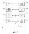
- FIG. 3is a functional block diagram illustrating the components that comprise the storage device 126 .
- the storage device 126includes a storage media 180 , such as a magnetic storage media or optical storage media. It should be noted that in some cases, the storage media 180 may be physically removed from the storage device 126 , as in the case of a removable disk.
- the storage device 126comprises a motor 182 and motor controller 184 .
- the motor 182is a direct drive motor while the motor control circuit 184 controls the motor speed.
- Other conventional componentssuch as a read/write head 186 , a read/write circuit 188 , and a head control circuit 190 , are also included in the storage device 126 .
- the read/write head 186contains a sensor, such as a magnetic sensor, to read and write data to and from the storage media 180 . If the storage media 180 is an optical device, such as a CD-ROM, the read/write head 186 may be an optical device. If the storage media 180 is a read-only device, such as an optical CD-ROM, the read/write head 186 is replaced simply by a read head (not shown).
- the read/write circuit 188contains conventional electronic circuitry to amplify the detected signal generated by the read/write head 186 .
- the head control circuit 190controls the position of the read/write head 186 and allows the read/write head to be positioned over the desired track on the storage media 180 .
- the operation of the read/write head 186 , read/write circuit 188 and head control circuit 190are well-known in the art and need not be described in any greater detail herein.
- the storage device 126contains a data buffer 192 and an I/O circuit 194 .
- the data buffer 192temporarily stores data retrieved from the storage media 180 during a READ operation or stores data to be transferred to the storage media during a WRITE operation.
- the operation of the data buffer 192is well-known and need not be described in any greater detail herein.
- the I/O circuit 194is coupled to the bus system 134 (see FIG. 1 ) and controls the flow of data and command instructions between the storage device 126 and the CPU 102 .
- the various portions of the storage device 126may be coupled together by an internal bus system 196 , which may comprise a power bus, data bus, control bus, or the like. For the sake of convenience, these busses are illustrated in FIG.
- the storage device 126is typically a commercial product, such as IDE hard drives or CD-ROMs from a number of different manufacturers, as well as microdrives and click-drives from companies, such as Microdrive, DataPlay, and Clik.
- the various components illustrated in FIG. 3may be collectively referred to as a disk controller 198 .
- the disk controllerreceives data and commands from the CPU 102 to read and write data to the storage media 180 .
- the BIOS portion of the memory 104provides instructions to control access to a selected track and/or cylinder of the storage media 180 .
- the storage device 126operates in a conventional manner to transfer data between the storage media 180 and the buffer 124 .
- the motor 182consumes a significant amount of power when active. Indeed, the motor 182 is the main source of power consumption in the system 100 . Accordingly, the system 100 maintains the motor 182 in a deactivated state until a data transfer is required. As will be discussed below, the system 100 must determine when to start the motor 182 so as to read data at an appropriate time. This is particularly important in audio applications where it is undesirable to have a break in the audio output stream.
- the system 100must determine ahead of time when data will be needed and start up the motor 182 in advance of the time when data will actually be needed so that data may be read from the storage media 180 and stored in the buffer 124 (see FIG. 1 ) for delivery to the CODEC 114 .
- the digital datais uncompressed.
- the raw data filesometimes referred to as a “Red Book Audio” file, consumes an extraordinary amount of storage space.
- musicis encoded at a sample rate of 44,100 Hertz per channel.
- a typical CODECutilizes 16 bit stereo samples for a total of almost 53 million bytes of data (26.46 million samples times 2 bytes per sample) for a five minute selection of music.
- utilization of the Red Book Audio filerequires significant storage capacity.
- many CODECsutilize a form of compression that greatly reduces the storage requirements.
- lossless compressionmay be possible, such compression is often limited in the overall reduction of storage requirements. For example, typical lossless compression may result in a 2:1 or 3:1 compression ratio. However, such lossless compression would still require 20-30 megabytes of storage for a five minute music sample. Other forms of compression do encounter some loss of information. However, such lossy compression has been satisfactorily implemented to eliminate portions of data samples that have little or no effect on the music heard by the user.
- MP3 compressionis one such form of lossy compression. With MP3 format encoding, it is possible to achieve compression ratios of 10:1.
- MP3 encodingis well-known in the art, the following brief description will assist in a better understanding of the present invention.
- MP3 systemsprocess the Red Book Audio wave by dividing the acoustic signal into a series of wavelets or frames. Fourier transformation of the wavelets from the time domain to the frequency domain is applied and frequencies compared using predetermined masking rules to eliminate frequencies that humans cannot typically hear. In addition, frequencies whose energy levels fall below a certain decibel limit, such that they are inaudible to the typical human ear, are also removed. Furthermore, some CODECs check for redundant information between the two channels of a stereo signal to delete redundant information between the two channels. Following such a signal processing, MP3 uses Huffman encoding for each frame.
- Frame header informationis prepended to the frame and the data stored in a file.
- This processis capable of achieving up to 10:1 compression ratio.
- the decoding processoccurs in essentially the opposite order with Huffman decoding of the frequency data and an inverse Fourier transformation to return the frequency data to the time domain.
- specialized interpolationsare performed between the data frames, in a process known as “windowing,” to generate the desired output signal.
- MP3transforms data into a series of frames.
- MP3requires fixed frame size of 384 bytes per frame with a frame equal to approximately 44 milliseconds.
- the CPU 102takes into account that the CODEC 114 (see FIG. 1 ) requires complete frames. Accordingly, if the system 100 is implemented using MP3 format, the data will be transferred in complete frames. This requires the transfer of data in multiples of 384 bytes (plus the prepended header) such that only complete frames are transferred.
- other data formatssuch as windows media format (sometimes referred to as WMA) uses a variable bit rate and allows frames to be repeated if there is little change from the previous data frame.
- the WMA formatallows a variable bit rate and allows data frames to be repeated thus providing greater efficiencies in utilization of data.
- the system 100can transfer a variable number of data bits from the storage media 180 (see FIG. 3 ) to the CPU 102 .
- the system 100utilizes a number of different buffering strategies in order to optimize data transfer from the storage device 126 .
- the system 100can dynamically allocate a number of different buffers when a particular application is instantiated. For example, the number of buffers, size of each buffer, and the number of full buffers to maintain are all variables that can be specified at the time an application is initially executed. This allows the behavior of the system to be tailored to the individual CODECs and the specific timing and efficiency requirements of each CODEC as well as the access time and data transfer rates of the storage device 126 .
- the systemwill maintain data in buffers for some period of time after the data has been transferred to the CODEC 114 to permit quick response to user requests to “Rewind” in the middle of a song.
- a number of buffershave been allocated for the storage of a music file.
- the data stored in the bufferscan be of many different types of format. Accordingly, the following description will generically refer to data because the principles can be applied to any format. For simplicity, assume that a megabyte of storage is available for the buffer 124 . Further, the buffer 124 may be readily broken down into a number of individual buffers. In the example, illustrated in FIGS. 4-9 , the buffer 124 has been subdivided into sixteen separate buffers. For convenience in illustrating the principles of the present invention, the buffers 1 - 16 are illustrated as contiguous buffers within the buffer 124 .
- the buffers 1 - 16need not be contiguous.
- the buffers 1 - 16need not be contiguous, nor need they be of uniform size.
- the system 100When a particular music data file or track has been selected by the user, the system 100 will initially activate the storage device 126 to extract the data therefrom to fill the entire buffer 124 . However, the system 100 need not wait until all 16 buffers are filled until music can be played via the CODEC 114 (see FIG. 1 ). For example, the system 100 can begin transferring data from the buffer 124 to the CODEC 114 as soon as buffer 1 is filled. Thus, buffers 2 - 16 will continue to receive data from the storage device while played out from the buffer 124 to the CODEC 114 . As illustrated in FIG. 4 , a pointer 199 indicates the current position within the buffer 124 where data is being read and transferred to the CODEC 114 .
- the data pointer 199is sometimes referred to as the “Read Point” for the buffer 124 . As data is transferred from the buffer 124 to the CODEC 114 , the read point 199 shifts to reflect the fact that data is being read out of the buffer 124 .
- the read point 199will shift sequentially through buffers 1 - 16 as the music track is played out via the CODEC 114 . At some point in time, the read point 199 will approach the end of the buffer 124 , which will require the transfer of additional data from the storage device 126 . As previously noted, the decision of when to activate the storage device 126 depends on factors such as the type of data file being played (e.g., music versus speech), the time for the motor 182 (see FIG. 3 ) to reach the proper speed, the data transfer rate of the storage device 126 , and the like.
- FIG. 5illustrates the activation of the storage device 126 when the read point 199 reaches a predetermined location in buffer 15 .
- the buffer 124must supply data to the CODEC 114 at the rate of 96,000 bytes per second. Accordingly, in the example illustrated in FIGS. 4-9 where each of the buffers 1 - 16 is 64 Kbytes in length, a single one of the buffers 1 - 16 provides approximately 0.68 seconds of data for the CODEC 114 .
- the time for the motor 182 to reach full speed when power is applied and the data transfer rate from the storage device 126 to the buffer 124can be readily determined. Thus, a simple calculation will provide the system with the location of the read point 199 when the storage device 126 must be activated to provide more data to the buffer 124 .
- the entire bufferwould be refilled with data from the storage device 126 .
- the usermay wish to backup or “Rewind” the device. If all the buffers 1 - 16 were refilled with new data, a rewind request from the user would require reactivation of the storage device 126 and the rebuffering of data for all of the buffers 1 - 16 .
- the system 100can reserve a portion of the buffer preceding the read point 199 . For example, FIG. 5 illustrates the position of the read point 199 in buffer 15 when the storage device 126 must be activated to replenish the data from buffers 1 - 14 .
- the system 100may reserve, by way of example, two buffers of data preceding the read point 199 .
- the storage device 126is activated when the read point 199 reaches a predetermined location in buffer 15 .
- the system 100may read sufficient data from the storage device 126 to fill buffers 1 - 12 of the buffer 124 .
- buffers 13 - 14contain approximately 1.25 seconds of data.
- the system 100may extract data from the storage device 126 to fill buffers 1 - 14 on the presumption that the read point 199 will be almost at the end of buffer 16 by the time buffers 1 - 14 are filled with data from the storage device 126 .
- the number of buffers reserved for a rewind operationcan be altered depending on the application. Accordingly, the present invention is not limited by the specific number of buffers utilized for a rewind operation.
- FIG. 6illustrates an example of a fast forward and rewind operation in which the user is moving the read point 199 within the range of the buffered data.
- the current read pointis in buffer 13 .
- the useractivates the input device 110 (see FIG. 1 ) to “Rewind” the musical track to a point within buffer 2 .
- the read pointis moved to the desired location within buffer 2 as illustrated by the reference numeral 199 ′.
- the system 100realizes greater efficiency in data transfers and avoids the unnecessary activation of the motor 182 (see FIG. 3 ).
- the useractivates the input device 110 (see FIG. 1 ) in a “Fast Forward” operation.
- the userhas activated the input device 110 to fast forward to a location within buffer 14 .
- the new read pointindicated by the reference numeral 199 ′′, is now at the user-selected location within buffer 14 .
- the fast forward operationmoves the read point 199 ′′ closer to the point in time where the contents of the buffer 124 must be refilled, as illustrated with respect to FIG. 5 .
- the usermay select a fast forward operation that moves the read point 199 ′′ past the location at which the storage device 126 must be activated in order to refill the contents of the buffer 124 . In that case, it will be necessary to activate the storage device 126 immediately so as to refill the buffer.
- the system 100has still realized greater efficiency in buffering by activating the storage device 126 only when necessary to fill large portions of the buffer 124 . Fast forward and rewind operations to points within the buffer do not necessarily require activation of the storage device 126 .
- the usermay initially jump to a location in a musical track that is not at the beginning of the musical track.
- the system 100will activate the storage device 126 to fill the buffer 124 in the manner previously described.
- the system 100may further allocate buffer space that precedes the user selected point in the musical track. This concept is illustrated in FIG. 7 , where buffers 1 - 16 are filled with data but wherein the read point 199 , which corresponds to the user-selected start point in the musical track, is set at the beginning of buffer 3 .
- buffers 1 - 2contain data that will not be played unless the user activates the rewind operation, as discussed above.
- Rewind operations that move the read point to locations within buffers 1 - 2are accomplished very quickly and do not require reactivation of the storage device 126 .
- Fast forward operationsare also accommodated in the manner described above. That is, fast forward operations that move the read point 199 to a location within the range of the buffer 124 are accomplished very quickly without activation of the storage device 126 .
- the usermay activate a fast forward operation to move the read point to a location beyond the range of the buffer 124 .
- Thisis illustrated in FIG. 8 where the read point, indicated by the reference numeral 199 ′′, has been moved to a location beyond the range of buffer 16 .
- the system 100can activate the storage device 126 to buffer ahead to the read point 199 ′′. This allows some of the already filled buffers to be maintained for possible use in a Rewind operation, as discussed above. However, the situation is limited by the latency of servicing the request (i.e., starting the motor 182 , waiting for the motor 182 to reach operational speed, and transferring the data from the storage media 180 ).
- the system 100will move the read pointer to the user selected location and fill the entire contents of the buffer in the manner illustrated in FIG. 7 .
- the usermay activate the input device 110 (see FIG. 1 ) to initiate a rewind operation that will move the read point 199 to a point prior in time to the range of the buffer 124 .
- Thisis illustrated in FIG. 9 where the user-selected location of the read point, designated by the reference numeral 199 ′, is earlier in time than the range of data contained in buffer 1 .
- the system 100activates the storage device 126 to “Backfill” data into the buffer 124 .
- the system 100need not load the entire contents of the buffer 124 to accommodate this request.
- FIG. 9illustrates an example where the read point 199 ′ is just before the range of buffer 1 .
- the system 100can backfill one or more buffers to provide data at least as far back as the new read point 199 ′.
- the systemmay provide additional buffering to accommodate future rewind requests by the user, as described above with respect to FIG. 7 .
- the system 100need not reload the entire contents of the buffer 124 .
- the read point 199is moved from buffer 15 to a location just prior to the range of buffer 1 .
- a single buffer of data(preceding buffer 1 in time) must be reloaded to accommodate the rewind requests from the user.
- buffers 1 - 15(which may be relabeled as labels 2 - 16 for the sake of convenience) need not be reloaded since they will be transferred to the CODEC 114 (see FIG. 1 ) without having to reactivate the storage device 126 .
- the storage device 126(see FIG. 1 ) is activated to fill the 600 kilobytes of buffer space.
- the remaining 400 kilobytes of buffer spaceneed not be reloaded since that data falls within the range of the buffer 124 and will be reused in the near future (barring possible additional rewind or fast forward operations.
- the buffering techniques provided by the system 100efficiently utilizes buffer space and minimizes operations that require the activation of the storage device 126 .
- Part of the efficiency provided by the buffering techniques of the system 100is that only one buffer is “Locked” for a reading to the CODEC 114 while the other buffers are available for read/write operations.
- sixteen buffersare allocated as part of the buffer 124 .
- only 1/16 of the total buffer spaceis locked for data transfer to the CODEC 114 and is thus unavailable for other read/write operations.
- the remaining 15/16 of the total buffer spaceare available to be filled each time the storage device 126 is activated.
- Such operationis in sharp contrast to a typical buffering operation in which a buffer is allocated into two portions with only one-half of the buffer space available for read/write operations while the other half of the buffer space is locked for data transfer operations to the CODEC.
- step 202the CPU 102 (see FIG. 1 ) sends commands to the storage device 126 to start the motor 182 (see FIG. 3 ).
- step 204the motor control circuit 184 determines whether the motor speed is satisfactory. As those skilled in the art can appreciate, the motor takes a brief predetermined period of time to reach operating speed. This time can be readily determined and, as will be discussed below, is one factor used to determine when to start the motor to read additional data from the storage media 180 .
- the disk controller 198reads a sufficient amount of data to fill the buffer 124 .
- step 210the motor is stopped in step 210 . As noted above, this significantly reduces the power consumption of the system 100 thereby significantly extending the life of the AAA batteries that comprise the power supply 132 (see FIG. 1 ).
- decision 212the system 100 determines whether additional data is needed. As noted above, the system 100 takes many factors into account to determine precisely when data is needed. While this includes normal data transfer from the buffer 124 to the CODEC 114 (see FIG. 1 ), as illustrated in FIGS. 4 and 5 , the process illustrated in decision 212 includes the various buffering strategies described above with respect to FIGS. 4-9 . If data is not presently needed, the result of decision 212 is NO and the system 100 returns to decision 212 until additional data is needed. At a time when additional data is needed, the result of decision 212 is YES. In step 216 , the CPU 102 (see FIG. 1 ) sends instructions to the disk controller 198 (see FIG. 3 ) to start the motor 182 .
- step 220the system 100 determines the quantity of data that will be required by the present disk transfer operation. It should be noted that step 220 may be executed after starting the motor 182 while waiting for the motor to reach proper operational speed. Alternatively, the calculation performed in step 220 may be done prior to starting the motor 182 or after the motor reaches operational speed. Those skilled in the art will appreciate that the quantity of data being transferred may vary depending on the point in time at which such calculation is made.
- the quantity of data neededwhich is calculated in step 220 , takes into account the amount of space available in the buffer 124 (see FIG. 1 ), the type of CODEC 114 , the type of drive (micro-drive versus click drive) and dynamically allocates buffers and buffer sizes.
- the systemcan allocate up to eight or more buffers to accommodate data transfers. For example, some drives are capable of transferring 512 K blocks of data. Under these circumstances, the system 100 will allocate sufficient number of buffers in the buffer 124 to accommodate the large block transfer size. Thus, the system 100 advantageously considers a number of variable factors in determining how much data to transfer and when such data transfers are required.
- step 224illustrated in FIG. 11 to determine whether the motor 182 (see FIG. 3 ) has reached the proper speed. If the motor 182 has not reached the proper speed, the result of decision 224 is NO and the system returns to decision 224 until the motor achieves the proper speed. When the motor 182 has reached the appropriate speed, the result of decision 224 is YES and, in step 226 , the system 100 transfers the required amount of data from the storage media 180 to the buffer 124 . In step 228 , the CPU sends instructions to the disk controller 198 (see FIG. 3 ) to stop the motor 182 . The data retrieval process ends at 230 .
- the buffer 124(see FIG. 1 ) has sufficient data such that the CODEC 114 receives a stream of data for conversion to analog form.
- the processing steps performed by the CODEC 114 to convert data stored in the buffer 124is known in the art, and need not be described in greater detail herein.
- different forms of CODECsare known in the industry and may be satisfactorily substituted into the system 100 . That is, the CODEC 114 may be selected for speech production, music production, or a combination of the two.
- the specific algorithms used by the CODECare known in the art and need not be described herein.
Landscapes
- Engineering & Computer Science (AREA)
- Multimedia (AREA)
- Signal Processing (AREA)
- Signal Processing For Digital Recording And Reproducing (AREA)
Abstract
Description
Claims (10)
Priority Applications (2)
| Application Number | Priority Date | Filing Date | Title |
|---|---|---|---|
| US09/975,749US7574272B2 (en) | 2000-10-13 | 2001-10-10 | System and method for data transfer optimization in a portable audio device |
| US12/239,660US20090018683A1 (en) | 2001-10-10 | 2008-09-26 | System and method for data transfer optimization in a portable audio device |
Applications Claiming Priority (2)
| Application Number | Priority Date | Filing Date | Title |
|---|---|---|---|
| US24077600P | 2000-10-13 | 2000-10-13 | |
| US09/975,749US7574272B2 (en) | 2000-10-13 | 2001-10-10 | System and method for data transfer optimization in a portable audio device |
Related Child Applications (1)
| Application Number | Title | Priority Date | Filing Date |
|---|---|---|---|
| US12/239,660ContinuationUS20090018683A1 (en) | 2001-10-10 | 2008-09-26 | System and method for data transfer optimization in a portable audio device |
Publications (2)
| Publication Number | Publication Date |
|---|---|
| US20020045961A1 US20020045961A1 (en) | 2002-04-18 |
| US7574272B2true US7574272B2 (en) | 2009-08-11 |
Family
ID=40253817
Family Applications (2)
| Application Number | Title | Priority Date | Filing Date |
|---|---|---|---|
| US09/975,749Expired - Fee RelatedUS7574272B2 (en) | 2000-10-13 | 2001-10-10 | System and method for data transfer optimization in a portable audio device |
| US12/239,660AbandonedUS20090018683A1 (en) | 2001-10-10 | 2008-09-26 | System and method for data transfer optimization in a portable audio device |
Family Applications After (1)
| Application Number | Title | Priority Date | Filing Date |
|---|---|---|---|
| US12/239,660AbandonedUS20090018683A1 (en) | 2001-10-10 | 2008-09-26 | System and method for data transfer optimization in a portable audio device |
Country Status (1)
| Country | Link |
|---|---|
| US (2) | US7574272B2 (en) |
Cited By (5)
| Publication number | Priority date | Publication date | Assignee | Title |
|---|---|---|---|---|
| US20100332754A1 (en)* | 2003-04-09 | 2010-12-30 | Corel Inc. | System and Method for Caching Multimedia Data |
| US20110150099A1 (en)* | 2009-12-21 | 2011-06-23 | Calvin Ryan Owen | Audio Splitting With Codec-Enforced Frame Sizes |
| US20160342528A1 (en)* | 2008-09-19 | 2016-11-24 | Microsoft Technology Licensing, Llc | Aggregation of write traffic to a data store |
| US9747248B2 (en) | 2006-06-20 | 2017-08-29 | Apple Inc. | Wireless communication system |
| US11334484B2 (en) | 2005-12-16 | 2022-05-17 | Microsoft Technology Licensing, Llc | Optimizing write and wear performance for a memory |
Families Citing this family (157)
| Publication number | Priority date | Publication date | Assignee | Title |
|---|---|---|---|---|
| US8645137B2 (en) | 2000-03-16 | 2014-02-04 | Apple Inc. | Fast, language-independent method for user authentication by voice |
| EP1425646A4 (en)* | 2001-08-16 | 2006-02-01 | Trans World New York Llc | User-personalized media sampling, recommendation and purchasing system using real-time inventory database |
| US6934812B1 (en) | 2001-10-22 | 2005-08-23 | Apple Computer, Inc. | Media player with instant play capability |
| US8151259B2 (en) | 2006-01-03 | 2012-04-03 | Apple Inc. | Remote content updates for portable media devices |
| US7433546B2 (en)* | 2004-10-25 | 2008-10-07 | Apple Inc. | Image scaling arrangement |
| JP2004118746A (en)* | 2002-09-27 | 2004-04-15 | Toshiba Corp | Electronic device and storage device startup control method |
| US7283443B2 (en)* | 2002-12-20 | 2007-10-16 | Koninklijke Philips Electronics N. V. | Power saving method for portable streaming devices |
| US7831199B2 (en) | 2006-01-03 | 2010-11-09 | Apple Inc. | Media data exchange, transfer or delivery for portable electronic devices |
| DE602004020271D1 (en)* | 2003-12-03 | 2009-05-07 | Koninkl Philips Electronics Nv | ENERGY SAVING PROCESS AND SYSTEM |
| US20050165501A1 (en)* | 2004-01-23 | 2005-07-28 | Lian Yam F. | Apparatus and method for the use of memory devices for audio |
| US8745132B2 (en) | 2004-09-10 | 2014-06-03 | Silver State Intellectual Technologies, Inc. | System and method for audio and video portable publishing system |
| KR100695127B1 (en)* | 2004-10-08 | 2007-03-14 | 삼성전자주식회사 | Multi-stage Speech Recognition Device and Method |
| US7706637B2 (en)* | 2004-10-25 | 2010-04-27 | Apple Inc. | Host configured for interoperation with coupled portable media player device |
| US7536565B2 (en)* | 2005-01-07 | 2009-05-19 | Apple Inc. | Techniques for improved playlist processing on media devices |
| US8300841B2 (en)* | 2005-06-03 | 2012-10-30 | Apple Inc. | Techniques for presenting sound effects on a portable media player |
| US7590772B2 (en) | 2005-08-22 | 2009-09-15 | Apple Inc. | Audio status information for a portable electronic device |
| US8677377B2 (en) | 2005-09-08 | 2014-03-18 | Apple Inc. | Method and apparatus for building an intelligent automated assistant |
| US7930369B2 (en) | 2005-10-19 | 2011-04-19 | Apple Inc. | Remotely configured media device |
| US20080162862A1 (en)* | 2005-12-02 | 2008-07-03 | Yoshiki Matsumoto | Signal Processing Apparatus and Signal Processing Method |
| US8654993B2 (en) | 2005-12-07 | 2014-02-18 | Apple Inc. | Portable audio device providing automated control of audio volume parameters for hearing protection |
| US8255640B2 (en) | 2006-01-03 | 2012-08-28 | Apple Inc. | Media device with intelligent cache utilization |
| US7673238B2 (en)* | 2006-01-05 | 2010-03-02 | Apple Inc. | Portable media device with video acceleration capabilities |
| US7848527B2 (en) | 2006-02-27 | 2010-12-07 | Apple Inc. | Dynamic power management in a portable media delivery system |
| US9137309B2 (en) | 2006-05-22 | 2015-09-15 | Apple Inc. | Calibration techniques for activity sensing devices |
| US7643895B2 (en) | 2006-05-22 | 2010-01-05 | Apple Inc. | Portable media device with workout support |
| US20070271116A1 (en) | 2006-05-22 | 2007-11-22 | Apple Computer, Inc. | Integrated media jukebox and physiologic data handling application |
| US8073984B2 (en) | 2006-05-22 | 2011-12-06 | Apple Inc. | Communication protocol for use with portable electronic devices |
| US8358273B2 (en)* | 2006-05-23 | 2013-01-22 | Apple Inc. | Portable media device with power-managed display |
| US7913297B2 (en)* | 2006-08-30 | 2011-03-22 | Apple Inc. | Pairing of wireless devices using a wired medium |
| US7813715B2 (en)* | 2006-08-30 | 2010-10-12 | Apple Inc. | Automated pairing of wireless accessories with host devices |
| US9318108B2 (en) | 2010-01-18 | 2016-04-19 | Apple Inc. | Intelligent automated assistant |
| US8341524B2 (en)* | 2006-09-11 | 2012-12-25 | Apple Inc. | Portable electronic device with local search capabilities |
| US8090130B2 (en) | 2006-09-11 | 2012-01-03 | Apple Inc. | Highly portable media devices |
| US7729791B2 (en)* | 2006-09-11 | 2010-06-01 | Apple Inc. | Portable media playback device including user interface event passthrough to non-media-playback processing |
| US7589629B2 (en)* | 2007-02-28 | 2009-09-15 | Apple Inc. | Event recorder for portable media device |
| US7698101B2 (en) | 2007-03-07 | 2010-04-13 | Apple Inc. | Smart garment |
| US8977255B2 (en) | 2007-04-03 | 2015-03-10 | Apple Inc. | Method and system for operating a multi-function portable electronic device using voice-activation |
| US9330720B2 (en) | 2008-01-03 | 2016-05-03 | Apple Inc. | Methods and apparatus for altering audio output signals |
| US9325951B2 (en) | 2008-03-03 | 2016-04-26 | Avigilon Patent Holding 2 Corporation | Content-aware computer networking devices with video analytics for reducing video storage and video communication bandwidth requirements of a video surveillance network camera system |
| US8427552B2 (en)* | 2008-03-03 | 2013-04-23 | Videoiq, Inc. | Extending the operational lifetime of a hard-disk drive used in video data storage applications |
| US8996376B2 (en) | 2008-04-05 | 2015-03-31 | Apple Inc. | Intelligent text-to-speech conversion |
| US10496753B2 (en) | 2010-01-18 | 2019-12-03 | Apple Inc. | Automatically adapting user interfaces for hands-free interaction |
| US9279461B2 (en)* | 2008-05-13 | 2016-03-08 | Borgwarner Inc. | Integrated memory chip for a coupling device |
| US20100030549A1 (en) | 2008-07-31 | 2010-02-04 | Lee Michael M | Mobile device having human language translation capability with positional feedback |
| WO2010067118A1 (en) | 2008-12-11 | 2010-06-17 | Novauris Technologies Limited | Speech recognition involving a mobile device |
| US9858925B2 (en) | 2009-06-05 | 2018-01-02 | Apple Inc. | Using context information to facilitate processing of commands in a virtual assistant |
| US10241752B2 (en) | 2011-09-30 | 2019-03-26 | Apple Inc. | Interface for a virtual digital assistant |
| US20120309363A1 (en) | 2011-06-03 | 2012-12-06 | Apple Inc. | Triggering notifications associated with tasks items that represent tasks to perform |
| US10241644B2 (en) | 2011-06-03 | 2019-03-26 | Apple Inc. | Actionable reminder entries |
| US9431006B2 (en) | 2009-07-02 | 2016-08-30 | Apple Inc. | Methods and apparatuses for automatic speech recognition |
| US10679605B2 (en) | 2010-01-18 | 2020-06-09 | Apple Inc. | Hands-free list-reading by intelligent automated assistant |
| US10553209B2 (en) | 2010-01-18 | 2020-02-04 | Apple Inc. | Systems and methods for hands-free notification summaries |
| US10705794B2 (en) | 2010-01-18 | 2020-07-07 | Apple Inc. | Automatically adapting user interfaces for hands-free interaction |
| US10276170B2 (en) | 2010-01-18 | 2019-04-30 | Apple Inc. | Intelligent automated assistant |
| DE112011100329T5 (en) | 2010-01-25 | 2012-10-31 | Andrew Peter Nelson Jerram | Apparatus, methods and systems for a digital conversation management platform |
| US8682667B2 (en) | 2010-02-25 | 2014-03-25 | Apple Inc. | User profiling for selecting user specific voice input processing information |
| US20120137102A1 (en)* | 2010-11-30 | 2012-05-31 | Ramkumar Perumanam | Consumer approach based memory buffer optimization for multimedia applications |
| US10762293B2 (en) | 2010-12-22 | 2020-09-01 | Apple Inc. | Using parts-of-speech tagging and named entity recognition for spelling correction |
| US9262612B2 (en) | 2011-03-21 | 2016-02-16 | Apple Inc. | Device access using voice authentication |
| JP5329602B2 (en)* | 2011-05-12 | 2013-10-30 | 株式会社三菱東京Ufj銀行 | Terminal device and program |
| US10057736B2 (en) | 2011-06-03 | 2018-08-21 | Apple Inc. | Active transport based notifications |
| US8484391B2 (en)* | 2011-06-20 | 2013-07-09 | Intel Corporation | Configurable buffer allocation for multi-format video processing |
| US8994660B2 (en) | 2011-08-29 | 2015-03-31 | Apple Inc. | Text correction processing |
| US10134385B2 (en) | 2012-03-02 | 2018-11-20 | Apple Inc. | Systems and methods for name pronunciation |
| US9483461B2 (en) | 2012-03-06 | 2016-11-01 | Apple Inc. | Handling speech synthesis of content for multiple languages |
| US9129001B2 (en)* | 2012-05-07 | 2015-09-08 | Sybase, Inc. | Character data compression for reducing storage requirements in a database system |
| US9280610B2 (en) | 2012-05-14 | 2016-03-08 | Apple Inc. | Crowd sourcing information to fulfill user requests |
| US9721563B2 (en) | 2012-06-08 | 2017-08-01 | Apple Inc. | Name recognition system |
| US9495129B2 (en) | 2012-06-29 | 2016-11-15 | Apple Inc. | Device, method, and user interface for voice-activated navigation and browsing of a document |
| US9576574B2 (en) | 2012-09-10 | 2017-02-21 | Apple Inc. | Context-sensitive handling of interruptions by intelligent digital assistant |
| US9547647B2 (en) | 2012-09-19 | 2017-01-17 | Apple Inc. | Voice-based media searching |
| DE212014000045U1 (en) | 2013-02-07 | 2015-09-24 | Apple Inc. | Voice trigger for a digital assistant |
| US9368114B2 (en) | 2013-03-14 | 2016-06-14 | Apple Inc. | Context-sensitive handling of interruptions |
| WO2014144579A1 (en) | 2013-03-15 | 2014-09-18 | Apple Inc. | System and method for updating an adaptive speech recognition model |
| AU2014233517B2 (en) | 2013-03-15 | 2017-05-25 | Apple Inc. | Training an at least partial voice command system |
| WO2014197334A2 (en) | 2013-06-07 | 2014-12-11 | Apple Inc. | System and method for user-specified pronunciation of words for speech synthesis and recognition |
| US9582608B2 (en) | 2013-06-07 | 2017-02-28 | Apple Inc. | Unified ranking with entropy-weighted information for phrase-based semantic auto-completion |
| WO2014197336A1 (en) | 2013-06-07 | 2014-12-11 | Apple Inc. | System and method for detecting errors in interactions with a voice-based digital assistant |
| WO2014197335A1 (en) | 2013-06-08 | 2014-12-11 | Apple Inc. | Interpreting and acting upon commands that involve sharing information with remote devices |
| DE112014002747T5 (en) | 2013-06-09 | 2016-03-03 | Apple Inc. | Apparatus, method and graphical user interface for enabling conversation persistence over two or more instances of a digital assistant |
| US10176167B2 (en) | 2013-06-09 | 2019-01-08 | Apple Inc. | System and method for inferring user intent from speech inputs |
| AU2014278595B2 (en) | 2013-06-13 | 2017-04-06 | Apple Inc. | System and method for emergency calls initiated by voice command |
| DE112014003653B4 (en) | 2013-08-06 | 2024-04-18 | Apple Inc. | Automatically activate intelligent responses based on activities from remote devices |
| US10190038B2 (en) | 2014-04-21 | 2019-01-29 | Baker Hughes, A Ge Company, Llc | Method of using sophorolipids in well treatment operations |
| US9620105B2 (en) | 2014-05-15 | 2017-04-11 | Apple Inc. | Analyzing audio input for efficient speech and music recognition |
| US10592095B2 (en) | 2014-05-23 | 2020-03-17 | Apple Inc. | Instantaneous speaking of content on touch devices |
| US9502031B2 (en) | 2014-05-27 | 2016-11-22 | Apple Inc. | Method for supporting dynamic grammars in WFST-based ASR |
| US10170123B2 (en) | 2014-05-30 | 2019-01-01 | Apple Inc. | Intelligent assistant for home automation |
| US10078631B2 (en) | 2014-05-30 | 2018-09-18 | Apple Inc. | Entropy-guided text prediction using combined word and character n-gram language models |
| CN110797019B (en) | 2014-05-30 | 2023-08-29 | 苹果公司 | Multi-command single speech input method |
| US9785630B2 (en) | 2014-05-30 | 2017-10-10 | Apple Inc. | Text prediction using combined word N-gram and unigram language models |
| US9715875B2 (en) | 2014-05-30 | 2017-07-25 | Apple Inc. | Reducing the need for manual start/end-pointing and trigger phrases |
| US9842101B2 (en) | 2014-05-30 | 2017-12-12 | Apple Inc. | Predictive conversion of language input |
| US9734193B2 (en) | 2014-05-30 | 2017-08-15 | Apple Inc. | Determining domain salience ranking from ambiguous words in natural speech |
| US9430463B2 (en) | 2014-05-30 | 2016-08-30 | Apple Inc. | Exemplar-based natural language processing |
| US9633004B2 (en) | 2014-05-30 | 2017-04-25 | Apple Inc. | Better resolution when referencing to concepts |
| US10289433B2 (en) | 2014-05-30 | 2019-05-14 | Apple Inc. | Domain specific language for encoding assistant dialog |
| US9760559B2 (en) | 2014-05-30 | 2017-09-12 | Apple Inc. | Predictive text input |
| US9338493B2 (en) | 2014-06-30 | 2016-05-10 | Apple Inc. | Intelligent automated assistant for TV user interactions |
| US10659851B2 (en) | 2014-06-30 | 2020-05-19 | Apple Inc. | Real-time digital assistant knowledge updates |
| US10446141B2 (en) | 2014-08-28 | 2019-10-15 | Apple Inc. | Automatic speech recognition based on user feedback |
| US9818400B2 (en) | 2014-09-11 | 2017-11-14 | Apple Inc. | Method and apparatus for discovering trending terms in speech requests |
| US10789041B2 (en) | 2014-09-12 | 2020-09-29 | Apple Inc. | Dynamic thresholds for always listening speech trigger |
| US9886432B2 (en) | 2014-09-30 | 2018-02-06 | Apple Inc. | Parsimonious handling of word inflection via categorical stem + suffix N-gram language models |
| US10127911B2 (en) | 2014-09-30 | 2018-11-13 | Apple Inc. | Speaker identification and unsupervised speaker adaptation techniques |
| US9668121B2 (en) | 2014-09-30 | 2017-05-30 | Apple Inc. | Social reminders |
| US9646609B2 (en) | 2014-09-30 | 2017-05-09 | Apple Inc. | Caching apparatus for serving phonetic pronunciations |
| US10074360B2 (en) | 2014-09-30 | 2018-09-11 | Apple Inc. | Providing an indication of the suitability of speech recognition |
| US10552013B2 (en) | 2014-12-02 | 2020-02-04 | Apple Inc. | Data detection |
| US9711141B2 (en) | 2014-12-09 | 2017-07-18 | Apple Inc. | Disambiguating heteronyms in speech synthesis |
| US9865280B2 (en) | 2015-03-06 | 2018-01-09 | Apple Inc. | Structured dictation using intelligent automated assistants |
| US9721566B2 (en) | 2015-03-08 | 2017-08-01 | Apple Inc. | Competing devices responding to voice triggers |
| US10567477B2 (en) | 2015-03-08 | 2020-02-18 | Apple Inc. | Virtual assistant continuity |
| US9886953B2 (en) | 2015-03-08 | 2018-02-06 | Apple Inc. | Virtual assistant activation |
| US9899019B2 (en) | 2015-03-18 | 2018-02-20 | Apple Inc. | Systems and methods for structured stem and suffix language models |
| US9842105B2 (en) | 2015-04-16 | 2017-12-12 | Apple Inc. | Parsimonious continuous-space phrase representations for natural language processing |
| US10083688B2 (en) | 2015-05-27 | 2018-09-25 | Apple Inc. | Device voice control for selecting a displayed affordance |
| US10127220B2 (en) | 2015-06-04 | 2018-11-13 | Apple Inc. | Language identification from short strings |
| US10101822B2 (en) | 2015-06-05 | 2018-10-16 | Apple Inc. | Language input correction |
| US9578173B2 (en) | 2015-06-05 | 2017-02-21 | Apple Inc. | Virtual assistant aided communication with 3rd party service in a communication session |
| US10255907B2 (en) | 2015-06-07 | 2019-04-09 | Apple Inc. | Automatic accent detection using acoustic models |
| US10186254B2 (en) | 2015-06-07 | 2019-01-22 | Apple Inc. | Context-based endpoint detection |
| US11025565B2 (en) | 2015-06-07 | 2021-06-01 | Apple Inc. | Personalized prediction of responses for instant messaging |
| US10671428B2 (en) | 2015-09-08 | 2020-06-02 | Apple Inc. | Distributed personal assistant |
| US10747498B2 (en) | 2015-09-08 | 2020-08-18 | Apple Inc. | Zero latency digital assistant |
| US9697820B2 (en) | 2015-09-24 | 2017-07-04 | Apple Inc. | Unit-selection text-to-speech synthesis using concatenation-sensitive neural networks |
| US10366158B2 (en) | 2015-09-29 | 2019-07-30 | Apple Inc. | Efficient word encoding for recurrent neural network language models |
| US11010550B2 (en) | 2015-09-29 | 2021-05-18 | Apple Inc. | Unified language modeling framework for word prediction, auto-completion and auto-correction |
| US11587559B2 (en) | 2015-09-30 | 2023-02-21 | Apple Inc. | Intelligent device identification |
| US10691473B2 (en) | 2015-11-06 | 2020-06-23 | Apple Inc. | Intelligent automated assistant in a messaging environment |
| US10049668B2 (en) | 2015-12-02 | 2018-08-14 | Apple Inc. | Applying neural network language models to weighted finite state transducers for automatic speech recognition |
| US10223066B2 (en) | 2015-12-23 | 2019-03-05 | Apple Inc. | Proactive assistance based on dialog communication between devices |
| US10446143B2 (en) | 2016-03-14 | 2019-10-15 | Apple Inc. | Identification of voice inputs providing credentials |
| US9934775B2 (en) | 2016-05-26 | 2018-04-03 | Apple Inc. | Unit-selection text-to-speech synthesis based on predicted concatenation parameters |
| US9972304B2 (en) | 2016-06-03 | 2018-05-15 | Apple Inc. | Privacy preserving distributed evaluation framework for embedded personalized systems |
| US10249300B2 (en) | 2016-06-06 | 2019-04-02 | Apple Inc. | Intelligent list reading |
| US10049663B2 (en) | 2016-06-08 | 2018-08-14 | Apple, Inc. | Intelligent automated assistant for media exploration |
| DK179309B1 (en) | 2016-06-09 | 2018-04-23 | Apple Inc | Intelligent automated assistant in a home environment |
| US10067938B2 (en) | 2016-06-10 | 2018-09-04 | Apple Inc. | Multilingual word prediction |
| US10490187B2 (en) | 2016-06-10 | 2019-11-26 | Apple Inc. | Digital assistant providing automated status report |
| US10586535B2 (en) | 2016-06-10 | 2020-03-10 | Apple Inc. | Intelligent digital assistant in a multi-tasking environment |
| US10192552B2 (en) | 2016-06-10 | 2019-01-29 | Apple Inc. | Digital assistant providing whispered speech |
| US10509862B2 (en) | 2016-06-10 | 2019-12-17 | Apple Inc. | Dynamic phrase expansion of language input |
| DK179415B1 (en) | 2016-06-11 | 2018-06-14 | Apple Inc | Intelligent device arbitration and control |
| DK179049B1 (en) | 2016-06-11 | 2017-09-18 | Apple Inc | Data driven natural language event detection and classification |
| DK201670540A1 (en) | 2016-06-11 | 2018-01-08 | Apple Inc | Application integration with a digital assistant |
| DK179343B1 (en) | 2016-06-11 | 2018-05-14 | Apple Inc | Intelligent task discovery |
| US10043516B2 (en) | 2016-09-23 | 2018-08-07 | Apple Inc. | Intelligent automated assistant |
| US10593346B2 (en) | 2016-12-22 | 2020-03-17 | Apple Inc. | Rank-reduced token representation for automatic speech recognition |
| EP4116972B1 (en)* | 2017-02-24 | 2025-06-25 | Panasonic Intellectual Property Management Co., Ltd. | Optical disc drive device and playback device |
| DK201770439A1 (en) | 2017-05-11 | 2018-12-13 | Apple Inc. | Offline personal assistant |
| DK179496B1 (en) | 2017-05-12 | 2019-01-15 | Apple Inc. | USER-SPECIFIC Acoustic Models |
| DK179745B1 (en) | 2017-05-12 | 2019-05-01 | Apple Inc. | SYNCHRONIZATION AND TASK DELEGATION OF A DIGITAL ASSISTANT |
| DK201770432A1 (en) | 2017-05-15 | 2018-12-21 | Apple Inc. | Hierarchical belief states for digital assistants |
| DK201770431A1 (en) | 2017-05-15 | 2018-12-20 | Apple Inc. | Optimizing dialogue policy decisions for digital assistants using implicit feedback |
| DK179549B1 (en) | 2017-05-16 | 2019-02-12 | Apple Inc. | Far-field extension for digital assistant services |
| CN107633034B (en)* | 2017-09-08 | 2020-12-01 | 河南德朗智能科技有限公司 | Multi-buffer queue parallel storage method |
Citations (5)
| Publication number | Priority date | Publication date | Assignee | Title |
|---|---|---|---|---|
| US5477511A (en)* | 1994-07-13 | 1995-12-19 | Englehardt; C. Duane | Portable documentation system |
| US5720037A (en)* | 1994-06-16 | 1998-02-17 | Lucent Technologies Inc. | Multimedia on-demand server |
| US6332175B1 (en)* | 1999-02-12 | 2001-12-18 | Compaq Computer Corporation | Low power system and method for playing compressed audio data |
| US6378035B1 (en)* | 1999-04-06 | 2002-04-23 | Microsoft Corporation | Streaming information appliance with buffer read and write synchronization |
| US6791481B2 (en)* | 2000-05-18 | 2004-09-14 | Echo Mobile Music, Llc | Portable CD-ROM/ISO to HDD/MP3 recorder with simultaneous CD-Read/MP3-Encode/HDD-Write, or HDD-Read/MP3-Decode, to play, power saving buffer, and enhanced sound output |
Family Cites Families (2)
| Publication number | Priority date | Publication date | Assignee | Title |
|---|---|---|---|---|
| JP5166074B2 (en)* | 2008-02-29 | 2013-03-21 | 株式会社東芝 | Semiconductor memory device, control method thereof, and error correction system |
| JP4856110B2 (en)* | 2008-03-01 | 2012-01-18 | 株式会社東芝 | Chain search apparatus and chain search method |
- 2001
- 2001-10-10USUS09/975,749patent/US7574272B2/ennot_activeExpired - Fee Related
- 2008
- 2008-09-26USUS12/239,660patent/US20090018683A1/ennot_activeAbandoned
Patent Citations (5)
| Publication number | Priority date | Publication date | Assignee | Title |
|---|---|---|---|---|
| US5720037A (en)* | 1994-06-16 | 1998-02-17 | Lucent Technologies Inc. | Multimedia on-demand server |
| US5477511A (en)* | 1994-07-13 | 1995-12-19 | Englehardt; C. Duane | Portable documentation system |
| US6332175B1 (en)* | 1999-02-12 | 2001-12-18 | Compaq Computer Corporation | Low power system and method for playing compressed audio data |
| US6378035B1 (en)* | 1999-04-06 | 2002-04-23 | Microsoft Corporation | Streaming information appliance with buffer read and write synchronization |
| US6791481B2 (en)* | 2000-05-18 | 2004-09-14 | Echo Mobile Music, Llc | Portable CD-ROM/ISO to HDD/MP3 recorder with simultaneous CD-Read/MP3-Encode/HDD-Write, or HDD-Read/MP3-Decode, to play, power saving buffer, and enhanced sound output |
Non-Patent Citations (4)
| Title |
|---|
| Compaq's System Research Center, Personal Jukebox, google cache date is Dec. 14, 2005, http://research.compaq.com/SRC/pjb.* |
| Compaq's System Research Center, Personal Jukebox, unknown date, http://research.compaq.com/SRC/pjb.* |
| GNU.org, Unix Man pp. dd (1), Nov. 1998, http://www.rt.com/man/dd.1.html.* |
| HanGo Electronics, Personal Jukebox, Feb. 29, 2000, http://web.archive.org/web/20000229023013/www.pjbox.com/product.htm.* |
Cited By (11)
| Publication number | Priority date | Publication date | Assignee | Title |
|---|---|---|---|---|
| US20100332754A1 (en)* | 2003-04-09 | 2010-12-30 | Corel Inc. | System and Method for Caching Multimedia Data |
| US8924643B2 (en) | 2003-04-09 | 2014-12-30 | 8324450 Canada Inc. | System and method for caching multimedia data |
| US11334484B2 (en) | 2005-12-16 | 2022-05-17 | Microsoft Technology Licensing, Llc | Optimizing write and wear performance for a memory |
| US9747248B2 (en) | 2006-06-20 | 2017-08-29 | Apple Inc. | Wireless communication system |
| US20160342528A1 (en)* | 2008-09-19 | 2016-11-24 | Microsoft Technology Licensing, Llc | Aggregation of write traffic to a data store |
| US10509730B2 (en)* | 2008-09-19 | 2019-12-17 | Microsoft Technology Licensing, Llc | Aggregation of write traffic to a data store |
| US20110150099A1 (en)* | 2009-12-21 | 2011-06-23 | Calvin Ryan Owen | Audio Splitting With Codec-Enforced Frame Sizes |
| WO2011084823A1 (en)* | 2009-12-21 | 2011-07-14 | Echostar Advanced Technologies L.L.C. | Audio splitting with codec-enforced frame sizes |
| CN102713883A (en)* | 2009-12-21 | 2012-10-03 | 艾科星先进科技公司 | Audio splitting with codec-enforced frame size |
| US9338523B2 (en) | 2009-12-21 | 2016-05-10 | Echostar Technologies L.L.C. | Audio splitting with codec-enforced frame sizes |
| CN102713883B (en)* | 2009-12-21 | 2016-09-28 | 艾科星科技公司 | Audio splitting with codec-enforced frame size |
Also Published As
| Publication number | Publication date |
|---|---|
| US20020045961A1 (en) | 2002-04-18 |
| US20090018683A1 (en) | 2009-01-15 |
Similar Documents
| Publication | Publication Date | Title |
|---|---|---|
| US7574272B2 (en) | System and method for data transfer optimization in a portable audio device | |
| US6332175B1 (en) | Low power system and method for playing compressed audio data | |
| US6377530B1 (en) | System and method for playing compressed audio data | |
| US6675233B1 (en) | Audio controller for portable electronic devices | |
| US6954804B2 (en) | Controller for portable electronic devices | |
| KR100913843B1 (en) | Method and apparatus for lapse play timekeeping of variable bit rate digitally encoded audio data files | |
| EP1381955B1 (en) | Low power digital audio decoding/playing system for computing devices | |
| US20020087225A1 (en) | Portable computing device having a low power media player | |
| US20090279398A1 (en) | Portable recorder/players with power-saving buffers | |
| US7526349B2 (en) | Low power digital audio decoding/playing system for computing devices | |
| EP1257895B1 (en) | Audio controller for portable electronic devices | |
| US20030060911A1 (en) | Low power digital audio decoding/playing system for computing devices | |
| US7283443B2 (en) | Power saving method for portable streaming devices | |
| US20040042768A1 (en) | Apparatus and control method for recording and reproducing audio-video data | |
| KR20010069858A (en) | System and method for playing multimedia file | |
| US6430530B1 (en) | Apparatus for automatically processing both encoded and unencoded data | |
| US7751690B2 (en) | Recording and reproducing apparatus | |
| JP2008269745A (en) | Reproducing device, program, and reproducing method | |
| US8185223B2 (en) | Multimedia playing method and apparatus using the same | |
| KR20080061071A (en) | Multifunction Voice Recorder Pen | |
| JP2005078690A (en) | Recording and reproduction control apparatus and method, and recording medium |
Legal Events
| Date | Code | Title | Description |
|---|---|---|---|
| AS | Assignment | Owner name:INTERACTIVE OBJECTS, INC., WASHINGTON Free format text:ASSIGNMENT OF ASSIGNORS INTEREST;ASSIGNORS:GIBBS, ERIC P.;PHILLIPS, MARK E.;REEL/FRAME:012543/0785 Effective date:20011213 | |
| AS | Assignment | Owner name:MARK E. PHILLIPS, WASHINGTON Free format text:ASSIGNMENT OF ASSIGNORS INTEREST;ASSIGNOR:FULLPLAY MEDIA SYSTEMS, INC.;REEL/FRAME:017884/0537 Effective date:20060330 | |
| STCF | Information on status: patent grant | Free format text:PATENTED CASE | |
| AS | Assignment | Owner name:FULLPLAY MEDIA SYSTEMS, INC.,WASHINGTON Free format text:CHANGE OF NAME;ASSIGNOR:INTERACTIVE OBJECTS, INC.;REEL/FRAME:024547/0013 Effective date:20011227 | |
| AS | Assignment | Owner name:HUNTS POINT VENTURES, INC., WASHINGTON Free format text:ASSIGNMENT OF ASSIGNORS INTEREST;ASSIGNOR:PHILLIPS, MARK E.;REEL/FRAME:026110/0603 Effective date:20110123 | |
| RR | Request for reexamination filed | Effective date:20120507 | |
| REMI | Maintenance fee reminder mailed | ||
| FPAY | Fee payment | Year of fee payment:4 | |
| SULP | Surcharge for late payment | ||
| AS | Assignment | Owner name:SCHWEICKERT, JENNIFER, WASHINGTON Free format text:COURT ORDER;ASSIGNOR:HUNTS POINT VENTURES, INC.;REEL/FRAME:036555/0468 Effective date:20150624 | |
| REMI | Maintenance fee reminder mailed | ||
| CONR | Reexamination decision confirms claims | Kind code of ref document:C1 Free format text:REEXAMINATION CERTIFICATE Filing date:20120507 Effective date:20170721 | |
| FPAY | Fee payment | Year of fee payment:8 | |
| SULP | Surcharge for late payment | Year of fee payment:7 | |
| FEPP | Fee payment procedure | Free format text:MAINTENANCE FEE REMINDER MAILED (ORIGINAL EVENT CODE: REM.); ENTITY STATUS OF PATENT OWNER: SMALL ENTITY | |
| LAPS | Lapse for failure to pay maintenance fees | Free format text:PATENT EXPIRED FOR FAILURE TO PAY MAINTENANCE FEES (ORIGINAL EVENT CODE: EXP.); ENTITY STATUS OF PATENT OWNER: SMALL ENTITY | |
| STCH | Information on status: patent discontinuation | Free format text:PATENT EXPIRED DUE TO NONPAYMENT OF MAINTENANCE FEES UNDER 37 CFR 1.362 | |
| FP | Lapsed due to failure to pay maintenance fee | Effective date:20210811 |