US7573682B2 - Writer heater for thermal protrusion shape control in a magnetic writer - Google Patents
Writer heater for thermal protrusion shape control in a magnetic writerDownload PDFInfo
- Publication number
- US7573682B2 US7573682B2US11/154,223US15422305AUS7573682B2US 7573682 B2US7573682 B2US 7573682B2US 15422305 AUS15422305 AUS 15422305AUS 7573682 B2US7573682 B2US 7573682B2
- Authority
- US
- United States
- Prior art keywords
- heating element
- coil
- writer
- heater
- conductor
- Prior art date
- Legal status (The legal status is an assumption and is not a legal conclusion. Google has not performed a legal analysis and makes no representation as to the accuracy of the status listed.)
- Active, expires
Links
Images


Classifications
- G—PHYSICS
- G11—INFORMATION STORAGE
- G11B—INFORMATION STORAGE BASED ON RELATIVE MOVEMENT BETWEEN RECORD CARRIER AND TRANSDUCER
- G11B5/00—Recording by magnetisation or demagnetisation of a record carrier; Reproducing by magnetic means; Record carriers therefor
- G11B5/127—Structure or manufacture of heads, e.g. inductive
- G11B5/31—Structure or manufacture of heads, e.g. inductive using thin films
- G11B5/3109—Details
- G11B5/313—Disposition of layers
- G11B5/3133—Disposition of layers including layers not usually being a part of the electromagnetic transducer structure and providing additional features, e.g. for improving heat radiation, reduction of power dissipation, adaptations for measurement or indication of gap depth or other properties of the structure
- G—PHYSICS
- G11—INFORMATION STORAGE
- G11B—INFORMATION STORAGE BASED ON RELATIVE MOVEMENT BETWEEN RECORD CARRIER AND TRANSDUCER
- G11B5/00—Recording by magnetisation or demagnetisation of a record carrier; Reproducing by magnetic means; Record carriers therefor
- G11B5/127—Structure or manufacture of heads, e.g. inductive
- G11B5/31—Structure or manufacture of heads, e.g. inductive using thin films
- G11B5/3109—Details
- G11B5/3116—Shaping of layers, poles or gaps for improving the form of the electrical signal transduced, e.g. for shielding, contour effect, equalizing, side flux fringing, cross talk reduction between heads or between heads and information tracks
- G—PHYSICS
- G11—INFORMATION STORAGE
- G11B—INFORMATION STORAGE BASED ON RELATIVE MOVEMENT BETWEEN RECORD CARRIER AND TRANSDUCER
- G11B5/00—Recording by magnetisation or demagnetisation of a record carrier; Reproducing by magnetic means; Record carriers therefor
- G11B5/48—Disposition or mounting of heads or head supports relative to record carriers ; arrangements of heads, e.g. for scanning the record carrier to increase the relative speed
- G11B5/58—Disposition or mounting of heads or head supports relative to record carriers ; arrangements of heads, e.g. for scanning the record carrier to increase the relative speed with provision for moving the head for the purpose of maintaining alignment of the head relative to the record carrier during transducing operation, e.g. to compensate for surface irregularities of the latter or for track following
- G11B5/60—Fluid-dynamic spacing of heads from record-carriers
- G11B5/6005—Specially adapted for spacing from a rotating disc using a fluid cushion
- G11B5/6011—Control of flying height
- G11B5/6064—Control of flying height using air pressure
- G—PHYSICS
- G11—INFORMATION STORAGE
- G11B—INFORMATION STORAGE BASED ON RELATIVE MOVEMENT BETWEEN RECORD CARRIER AND TRANSDUCER
- G11B5/00—Recording by magnetisation or demagnetisation of a record carrier; Reproducing by magnetic means; Record carriers therefor
- G11B5/48—Disposition or mounting of heads or head supports relative to record carriers ; arrangements of heads, e.g. for scanning the record carrier to increase the relative speed
- G11B5/58—Disposition or mounting of heads or head supports relative to record carriers ; arrangements of heads, e.g. for scanning the record carrier to increase the relative speed with provision for moving the head for the purpose of maintaining alignment of the head relative to the record carrier during transducing operation, e.g. to compensate for surface irregularities of the latter or for track following
- G11B5/60—Fluid-dynamic spacing of heads from record-carriers
- G11B5/6005—Specially adapted for spacing from a rotating disc using a fluid cushion
- G11B5/6011—Control of flying height
- G11B5/607—Control of flying height using thermal means
Definitions
- a magnetic headtypically includes a writer portion for storing magnetically-encoded information on a magnetic media and a reader portion for retrieving the magnetically-encoded information from the magnetic media.
- a writer portionfor storing magnetically-encoded information on a magnetic media
- a reader portionfor retrieving the magnetically-encoded information from the magnetic media.
- an electrical currentis caused to flow through a conductive coil to induce a magnetic field in a write pole.
- the magnetic headis positioned in close proximity to the magnetic media.
- the distance between the magnetic head and the mediais preferably small enough to allow for writing to and reading from the magnetic media with a large areal density, and great enough to prevent contact between the magnetic media and the magnetic head.
- Performance of the magnetic headdepends primarily upon head-media spacing (HMS).
- High density recordingpreferably requires a small HMS and a low fly height. Prior to using each magnetic head, there are small variations in fly height that must be accounted for due to changing operating conditions and head-to-head variations.
- the heateris typically placed close to, or even inside, the writer coil to maximize heating of the writer.
- the heatermust provide a large enough heater stroke when the write pole is either close to the magnetic media or only slightly recessed from the point at the storage interface surface where the writer protrudes most.
- the fly clearancemust be measured for each magnetic head by a controlled measurable non-destructive head-media contact so that the proper algorithm for operating the heater is used for each magnetic head.
- the head-media contactis typically detected by a signal that changes sharply when the head mechanically contacts a lube layer of the magnetic media.
- the signalcould be ⁇ PES (position error signal).
- ⁇ PESposition error signal
- the surface area of the head-media contactmust be large enough so that when the thermally protruded magnetic head hits the lube layer of the magnetic media, the magnetic head component protruding most at the storage interface surface does not penetrate past the lube layer and start burnishing on the hard media surface, destroying the protective magnetic head layer.
- the storage interface surface topologycan also largely impact the ability to detect contact between the magnetic head and the lube layer.
- the write poleis positioned far away from the other metallic components of the head at the storage interface surface and protrudes above the surrounding alumina at a distance either comparable to, or greater than, the thickness of the lube layer, then the write pole can penetrate through the lube layer and burnish before a large enough head-media contact between the magnetic head and the lube layer is generated to be detectable.
- the inventionis a transducing device having a storage interface surface, a writer having a tip region, a coil having a width positioned around the writer, and a heater.
- the heaterextends to near the storage interface surface. A portion of the heater is at least as wide as the coil.
- the inventionis a heater for heating a magnetic writer having a storage interface surface, a pole tip region, and a coil positioned around the writer.
- the heaterincludes a first heating element and a second heating element.
- the first heating elementextends to near the storage interface surface adjacent first and second sides of the coil.
- the second heating elementis positioned behind the first heating element.
- the inventionis a writer having a storage interface surface, a pole tip region, and a heating element.
- the heating elementextends to the storage interface surface and is shaped adjacent the storage interface surface to produce a substantially uniform protruded head-media contact surface by thermal protrusion.
- FIG. 1is a sectional view of a magnetic head in accord with the present invention having a heating element.
- FIG. 2is a top view of a first embodiment of the magnetic head in accord with the present invention as taken along lines A-A of FIG. 1 .
- FIG. 3is a top view of a second embodiment of the magnetic head in accord with the present invention as taken along lines A-A of FIG. 1 .
- FIG. 4is a top view of the magnetic head in accord with the present invention having 0% of its total heat generated from a second heating element.
- FIG. 5is a top view of a the magnetic head in accord with the present invention having 15% of its total heat generated from the second heating element.
- FIG. 6is a top view of the magnetic head in accord with the present invention having 25% of its total heat generated from the second heating element.
- FIG. 7is a top view of a third embodiment of the magnetic head in accord with the present invention as taken along lines A-A of FIG. 1 .
- FIG. 8is a top view of a fourth embodiment of the magnetic head in accord with the present invention as taken along lines A-A of FIG. 1 .
- FIG. 9is a top view of a fifth embodiment of the magnetic head in accord with the present invention as taken along lines A-A of FIG. 1 .
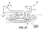
- FIG. 10is a top view of the magnetic head in accord with the present invention having a contact pad.
- FIG. 11is a storage interface surface view of a first embodiment of the contact pad of the magnetic head in accord with the present invention.
- FIG. 11Ais an enlarged view of region 11 A of FIG. 11 .
- FIG. 12Ais an enlarged view of region 12 A of FIG. 12 .
- FIG. 1is a sectional view of magnetic head 10 having heater 12 in accord with the present invention.
- Magnetic head 10generally comprises reader 14 and writer 16 , shown in FIG. 1 in a merged configuration.
- Reader 14includes bottom shield 18 , read element 20 , read gap 22 , and shared pole 24 (which acts as both a top shield and a return pole).
- Bottom shield 18is spaced from shared pole 24 by read gap 22 .
- Bottom shield 18 and shared pole 24are formed from metallic materials (preferably from an alloy composed primarily of Fe, Ni, and/or Co) that typically have a large CTE.
- a composition with about 80% Ni-20% Fe or 79% Ni-21% Fehas a CTE in the range of about 10.0 ⁇ 10 ⁇ 6 /° C. to 13.0 ⁇ 10 ⁇ 6 /° C.
- the change in resistivity of read element 20can be detected by passing a current through read element 20 and measuring a voltage across read element 20 .
- Other magnetic sensing technologiesmay also be used in the read element.
- Read element 20can be any type of read element, such as an anisotropic magnetoresistive (AMR) read element, a giant magnetoresistive (GMR) read element, or a tunneling giant magnetoresistive (TGMR) read element.
- AMRanisotropic magnetoresistive
- GMRgiant magnetoresistive
- TGMRtunneling giant magnetoresistive
- Read gap 22is generally formed of an insulating material, such as Al 2 O 3 .
- Writer 16includes heater 12 , shared pole 24 , write pole 26 , write pole tip 28 located at an end of write pole 26 at the storage interface surface, yoke 30 , return pole 32 , back via 34 , front shields 36 , write coil 38 (shown as upper coil turns 38 A, 38 B, and 38 C and lower coil turns 38 D, 38 E, and 38 F), and insulator 40 .
- magnetic head 10is shown having two return poles (i.e. shared pole 24 and return pole 32 ), writer 16 may have only one return pole or no return pole without departing from the intended scope of the invention.
- Shared pole 24 , write pole 26 , and return pole 32extend from the storage interface surface and are connected to each other distal from the storage interface surface by back via 34 .
- Yoke 30is formed on write pole 26 and is also connected to back via 34 , but does not extend the full length of write pole 26 .
- Front shields 36are connected to shared pole 24 and return pole 32 adjacent the storage interface surface and extend toward write pole tip 28 . Front shields 36 can be eliminated from writer 16 without departing from the intended scope of the invention.
- Insulator 40separates shared pole 24 , write pole 26 , and return pole 32 from each other and from coil 38 .
- Shared pole 24 , yoke 30 , return pole 32 , back via 34 , and front shields 36are formed from metallic ferromagnetic materials.
- each of these componentsis formed from an alloy composed primarily of Fe, Ni, and/or Co which typically has a large CTE.
- coil 38has upper coil turns 38 A, 38 B, and 38 C and lower coil turns 38 D, 38 E, and 38 F.
- Upper coil turns 38 A, 38 B, and 38 Care positioned between write pole 26 and return pole 32
- lower coil turns 38 D, 38 E, and 38 Fare positioned between shared pole 24 and write pole 26 .
- Coil turns 38 A, 38 B, 38 C, 38 D, 38 E, and 38 Fwrap around write pole 26 such that the flow of electrical current through conductive coil 38 generates a magnetic flux at write pole tip 28 .
- coil 38may be wrapped in the following order: 38 A to 38 D to 38 B to 38 E to 38 C to 38 F.
- Coil 38is generally formed from an electrically-conductive metal, such as Cu, Au, or Ag. Most commonly used is Cu, which has a CTE in the range of about 16.0 ⁇ 10 ⁇ 6 /° C. to 18.0 ⁇ 10 ⁇ 6 /° C.
- FIG. 1illustrates magnetic head 10 having a perpendicular writer and this specification discusses the invention primarily with respect to a perpendicular writer
- the present inventionmay be used in both a perpendicular writer and a longitudinal writer.
- the write poleis replaced with a top pole.
- shared pole 24can also include multiple layers, including a top shield, a non-magnetic layer, and a bottom pole.
- the present inventionmay also be used in a writer which comprises a write pole without a full magnetic yoke.
- FIG. 2is a top view of a first embodiment of magnetic head 10 of the present invention as taken along line A-A of FIG. 1 with insulator 40 removed.
- FIG. 2shows heater 12 , write pole 26 , write pole tip 28 , back via 34 , coil 38 wrapped around write pole 26 , and heater leads 39 .
- heater 12is comprised of first heating element 42 , which is the structure that falls below line 43 having heating conductors 44 and heater turns 46 extending through writer 16 .
- Heating conductors 44have a greater conductor width proximate pole tip 28 as shown at location 47 than proximate coil 38 as shown at heater turns 46 .
- first heating element 42is to generate a protrusion at the storage interface surface that is uniformly wide along the trailing edge direction near first side 48 and second side 50 of coil 38 , while generating much less protrusion at the AlTiC edge around write pole tip 28 .
- the thermal protrusionis necessary to ensure that when the fly height of writer 16 is being adjusted in relation to magnetic media M, write pole 26 is protected from burnishing.
- write pole 26Due to internal heating and the resulting thermal expansion of metallic components in writer 16 , write pole 26 is typically the component of writer 16 that protrudes the most at the storage interface surface. Thus, write pole 26 is commonly either used as head-media contact 52 or is positioned close to head-media contact 52 . Head-media contact 52 is the first contact point between magnetic head 10 and magnetic media M. The localized heating of writer 16 by heater 12 creates controlled thermal protrusion at the storage interface surface around write pole 26 in order to protect write pole 26 .
- the thermal protrusionis shaped to create a head-media contact surface 54 that is wide enough along the storage interface surface to ensure that writer 16 detects magnetic media M before head-media contact 52 penetrates through lube layer 56 of magnetic media M onto the hard media surface and destroys write pole 26 or another component of writer 16 .
- One example of a method of detecting contact between a head and mediais detection of a sharp increase of ⁇ PES (delta position error signal).
- ⁇ PESdelta position error signal
- Heating conductors 44 and heater turns 46 of first heating element 42are configured such that current I passing through first heating element 42 generates more heat close to the storage interface surface, where cooling occurs at a rapid rate, and generates less heat further away from the storage interface surface, where cooling occurs at a slow rate.
- This configuration of heating conductors 44provides heated volume with more uniform protrusion at the storage interface surface.
- first heating element 42emits a greater amount of heat because current I must pass around heater turns 46 .
- heating conductors 44are linear, current I flows straight through first heating element 42 without a significant build-up of heat.
- heating conductors 44 of first heating element 42also have varying conductor widths, which is the width of heating conductors 44 .
- width W Pthe width of heating conductors 44 .
- W Cthe conductor width of heating conductors 44 .
- FIG. 3is a top view of a second embodiment of magnetic head 10 .
- first heating element 42 and second heating element 58form heater 12 .
- Second heating element 58is positioned behind back via 34 and is connected between heater leads 39 and first heating element 42 .
- the purpose of second heating element 58is to provide an additional heat source behind coil 38 in order to controllably increase head-media contact surface 54 , even though it generates much less heat than first heating element 42 .
- head-media contact surface 54increases to provide an increasing flat thermal protrusion of writer 16 and head-media contact surface 54 .
- FIGS. 4-6show top views of magnetic head 10 having 0%, 15%, and 25% of the total heat in writer 16 generated by second heating element 58 , respectively, and the resulting thermal protrusion.
- the resulting thermal protrusion of magnetic head 10is substantially the same parallel to the plane of the paper. However, as more of the total heat is generated from second heating element 58 , the thermal protrusion of magnetic head 10 widens perpendicular to the plane of the paper.
- FIG. 4shows magnetic head 10 having 0% of its total heat generated from second heating element 58 and 100% of its total heat generated from first heating element 42 . Because second heating element 58 is not generating any heat, only heat from first heating element 42 pushes head-media contact surface 54 of writer 16 toward magnetic media M. When 100% of the heat from heater 12 is from first heating element 42 , there is no substantial head-media contact surface 54 , and the shape of the thermal protrusion perpendicular to the plane of the paper is long and narrow.
- FIG. 5is a top view of magnetic head 10 having approximately 15% of its total heat generated from second heating element 58 and approximately 85% of its total heat generated from first heating element 42 .
- heater 12comprises both first heating element 42 and second heating element 58
- head-media contact surface 54 and the thermal protrusion perpendicular to the plane of the paperbecomes wider.
- FIG. 6is a top view of magnetic head 10 having approximately 25% of its total heat generated from second heating element 58 and approximately 75% of its total heat generated from first heating element 42 .
- head-media contact surface 54becomes wider along the length of writer 16 .
- Head-media contact surface 54widens such that the thermal protrusion of writer 16 at the storage interface surface extends closer to first and second sides of coil 48 and 50 .
- the thermal protrusion of writer 16 perpendicular to the plane of the paperalso continues to widen when more heat is generated by second heating element 58 .
- FIGS. 7-9are top views of a third, fourth, and fifth embodiment of heater 12 of magnetic head 10 as taken along lines A-A of FIG. 1 , respectively.
- writer 16includes write pole 26 , but does not include magnetic yoke 30 as shown in FIG. 1 . Because writer 16 does not have a back via, heating conductors 44 of first heating element 42 can be symmetric.
- magnetic head 10has enhanced heating achieved by extending first heating element 42 past coil 38 .
- FIG. 8depicts the fourth embodiment of magnetic head 10 .
- Extra-wide thermal protrusionis achieved around write pole 26 at the storage interface surface by extending first heating element 42 past coil 38 and placing additional heater turns 46 past first and second sides of coil 48 and 50 . With additional heater turns 46 , more localized heat is provided at first and second sides 48 and 50 , causing a wider and more flat protrusion of head-media surface 54 .
- FIG. 10is a top view of magnetic head 10 having contact pad 60 .
- contact pad 60is positioned in close proximity to write pole 26 .
- Contact pad 60may be formed by building additional larger metallic components at the storage interface surface near write pole 26 or by using other functioning components of magnetic head 10 .
- contact pad 60may be built from shared pole 24 , return pole 32 , or front shields 36 (shown in FIG. 1 ).
- contact pad 60may be built specifically to provide the needed wide and flat head-media contact surface.
- contact pad 60is built from a material similar to write pole 26 so that it will expand at the same rate as write pole 26 .
- contact pad 60is needed in addition to a properly designed heater 12 to obtain a head-media contact surface large enough to detect contact between magnetic head 10 and the magnetic media before write pole 26 penetrates the lube layer and the head-media contact is destroyed. As the head-media contact surface increases in width, the chances of write pole 26 dipping past the lube layer onto the hard media surface of the magnetic media and burnishing write pole 26 decreases. Thus, contact pad 60 is needed to provide the extra thermal protrusion around write pole 26 .
- FIGS. 11 and 11Aare enlarged storage interface surface views of magnetic head 10 showing a first embodiment of contact pad 60 .
- contact pad 60is built from a single block 62 positioned above write pole 26 .
- Contact pad 60also covers a large area on either side of write pole 26 at the storage interface surface.
- Contact pad 60increases the thermal protrusion in the areas immediately surrounding write pole 26 such that head-media surface 54 covers a wide area around write pole 26 . This wide head-media surface 54 protects write pole 26 when writer 16 contacts magnetic media M.
- FIGS. 12 and 12Aare enlarged storage interface surface views of a second embodiment of contact pad 64 .
- contact pad 64consists of a pair of blocks 66 a and 66 b positioned on either side of write pole 26 .
- Blocks 66 a and 66 bprotect write pole 26 when writer 16 contacts magnetic media M by creating a more uniform head-media contact surface 54 at thermally protruded contact pad 64 and write pole 26 .
- this structurealso reduces stray field sensitivity.
- the magnetic head of the present inventioncomprises a heater for controlled thermal expansion of a writer at the storage interface surface.
- the protrusion created by the heaterprovides a large head-media contact surface in order to protect the write pole, as well as other components of the writer.
- the heateris typically comprised of a first heating element and a second heating element, although the second heating element is not necessary in all magnetic heads.
- the first heating elementspans the length of the storage interface surface near the pole tip region and extends to the first and second sides of the coil.
- the second heating elementgenerates heat behind the via and the coil. Current passing through the heater generates heat at the heating conductors and turns of the first heating element and the second heating element to provide localized heating of the writer.
- a contact padmay be necessary in order to achieve the desired wide, flat-shape thermal protrusion around the write pole.
- the write poleis typically used as the head-media contact and needs to be protected from burnishing when it comes into contact with the magnetic media.
- the contact padis built around the write pole and helps create a wide, flat-shaped protrusion around the write pole at the storage interface surface.
- the heater and contact pad of the present inventionallow heat to be generated in a controlled manner at the storage interface surface in order to provide a wide head-media contact surface.
Landscapes
- Engineering & Computer Science (AREA)
- Manufacturing & Machinery (AREA)
- Physics & Mathematics (AREA)
- Electromagnetism (AREA)
- Magnetic Heads (AREA)
Abstract
Description
Claims (16)
Priority Applications (1)
| Application Number | Priority Date | Filing Date | Title |
|---|---|---|---|
| US11/154,223US7573682B2 (en) | 2005-06-16 | 2005-06-16 | Writer heater for thermal protrusion shape control in a magnetic writer |
Applications Claiming Priority (1)
| Application Number | Priority Date | Filing Date | Title |
|---|---|---|---|
| US11/154,223US7573682B2 (en) | 2005-06-16 | 2005-06-16 | Writer heater for thermal protrusion shape control in a magnetic writer |
Publications (2)
| Publication Number | Publication Date |
|---|---|
| US20060285248A1 US20060285248A1 (en) | 2006-12-21 |
| US7573682B2true US7573682B2 (en) | 2009-08-11 |
Family
ID=37573114
Family Applications (1)
| Application Number | Title | Priority Date | Filing Date |
|---|---|---|---|
| US11/154,223Active2026-09-14US7573682B2 (en) | 2005-06-16 | 2005-06-16 | Writer heater for thermal protrusion shape control in a magnetic writer |
Country Status (1)
| Country | Link |
|---|---|
| US (1) | US7573682B2 (en) |
Cited By (35)
| Publication number | Priority date | Publication date | Assignee | Title |
|---|---|---|---|---|
| US20070274004A1 (en)* | 2006-05-19 | 2007-11-29 | Alps Electric Co., Ltd. | Thin film magnetic head having heating element |
| US20080094755A1 (en)* | 2006-10-18 | 2008-04-24 | Tdk Corporation | Thin-film magnetic head with heating portion and protrusion adjustment portion and manufacturing method of head |
| US20100246047A1 (en)* | 2009-03-31 | 2010-09-30 | Toshiba Storage Device Corporation | Magnetic head and information storage device |
| US20110273797A1 (en)* | 2010-05-10 | 2011-11-10 | International Business Machines Corporation | Write Head Having a Device for Reducing the Effects of Stray Flux |
| US20120077060A1 (en)* | 2010-03-29 | 2012-03-29 | Wd Media (Singapore) Pte. Ltd. | Evaluation method of magnetic disk, manufacturing method of magnetic disk, and magnetic disk |
| US20120092789A1 (en)* | 2010-10-14 | 2012-04-19 | Hitachi Global Storage Technologies Netherlands B.V. | Thermal fly height control magnetic recording head having a novel heating element geometry |
| US8456643B2 (en) | 2010-05-24 | 2013-06-04 | Western Digital (Fremont), Llc | Method and system for mapping the shape of a head under operating conditions |
| US8670214B1 (en) | 2011-12-20 | 2014-03-11 | Western Digital (Fremont), Llc | Method and system for providing enhanced thermal expansion for hard disk drives |
| US8681446B2 (en)* | 2011-12-21 | 2014-03-25 | Seagate Technology Llc | Methods and devices including multiple resistive heating elements |
| US8737005B1 (en) | 2011-01-06 | 2014-05-27 | Seagate Technology Llc | Adjusting heater current to reduce read transducer asymmetry |
| US8749920B1 (en) | 2011-12-16 | 2014-06-10 | Western Digital (Fremont), Llc | Magnetic recording head with dynamic fly height heating and having thermally controlled pole tip protrusion to control and protect reader element |
| US8760808B2 (en) | 2010-04-29 | 2014-06-24 | Seagate Technology Llc | Magnetic device containing a heater |
| US8786983B1 (en)* | 2012-06-25 | 2014-07-22 | Western Digital (Fremont), Llc | Magnetic writer having a low aspect ratio two layer coil |
| US8897104B1 (en) | 2013-04-02 | 2014-11-25 | Western Digital (Fremont), Llc | Method and system for performing off-disk measurements of laser-induced NFT protrusion in a heat assisted magnetic recording transducer |
| US9153266B1 (en) | 2014-09-11 | 2015-10-06 | Western Digital Technologies, Inc. | Data storage device measuring laser protrusion fly height profile |
| US9196275B1 (en) | 2014-03-12 | 2015-11-24 | Western Digital Technologies, Inc. | Magnetic head separator fin material to prevent particulate contamination on slider |
| US20160148629A1 (en)* | 2014-11-24 | 2016-05-26 | Seagate Technology Llc | Dual writer head design |
| US9484052B1 (en) | 2015-06-02 | 2016-11-01 | Seagate Technology Llc | Clearance adjustment for a head disk interface |
| US9508362B2 (en) | 2014-11-24 | 2016-11-29 | Seagate Technology Llc | Write management for interlaced magnetic recording devices |
| US9524743B2 (en) | 2014-11-24 | 2016-12-20 | Seagate Technology Llc | Heat assisted magnetic recording for bit-patterned media |
| US9586817B2 (en) | 2011-07-28 | 2017-03-07 | Seagate Technology Llc | Semi-auto scanning probe microscopy scanning |
| US9601154B2 (en) | 2014-11-24 | 2017-03-21 | Seagate Technology Llc | Prioritized random access for magnetic recording |
| US9672851B1 (en) | 2016-05-04 | 2017-06-06 | Seagate Technology Llc | Single writer interlaced magnetic recording |
| US9679601B2 (en) | 2014-11-24 | 2017-06-13 | Seagate Technology Llc | Post-write scan operations for interlaced magnetic recording |
| US9747942B2 (en) | 2014-11-24 | 2017-08-29 | Seagate Technology Llc | Variable written track widths for attribute-based storage |
| US9805741B1 (en) | 2016-01-29 | 2017-10-31 | Seagate Technology Llc | Write current parameter selection for magnetic recording |
| US9805744B1 (en) | 2016-04-01 | 2017-10-31 | Seagate Technology Llc | Dual writer design in interlaced magnetic recording |
| US9818445B2 (en) | 2016-01-12 | 2017-11-14 | Seagate Technology Llc | Magnetic storage device readers |
| US9842047B2 (en) | 2014-11-24 | 2017-12-12 | Seagate Technology Llc | Non-sequential write for sequential read back |
| US9852751B2 (en)* | 2016-03-14 | 2017-12-26 | Tdk Corporation | Thin film magnetic head, head gimbals assembly, head arm assembly, and magnetic disk unit with improved air bearing surface |
| US9858953B1 (en) | 2017-03-31 | 2018-01-02 | Seagate Technology Llc | Method of removing head contamination during contact detection |
| US10126326B2 (en) | 2006-04-28 | 2018-11-13 | Seagate Technology Llc | Atomic force microscopy of scanning and image processing |
| US10199066B1 (en) | 2018-03-01 | 2019-02-05 | Seagate Technology Llc | Write management of physically coupled storage areas |
| US10210891B1 (en) | 2016-01-28 | 2019-02-19 | Seagate Technology Llc | Dual writer head design utilizing two writers of different sizes for writing interlaced data tracks |
| US11830530B1 (en) | 2022-01-11 | 2023-11-28 | Seagate Technology Llc | Skew-independent close-point transducers |
Families Citing this family (16)
| Publication number | Priority date | Publication date | Assignee | Title |
|---|---|---|---|---|
| JP2007213749A (en)* | 2006-02-13 | 2007-08-23 | Fujitsu Ltd | Thin film magnetic head |
| US7423830B2 (en)* | 2006-04-10 | 2008-09-09 | Iomega Corporation | Detecting head/disk contact in a disk drive using a calibration parameter |
| JP2008027504A (en)* | 2006-07-20 | 2008-02-07 | Fujitsu Ltd | Magnetic head |
| US20100265618A1 (en)* | 2009-04-15 | 2010-10-21 | Zine-Eddine Boutaghou | Method and Apparatus for Reducing Head Media Spacing in a Disk Drive |
| US9221148B2 (en) | 2009-04-30 | 2015-12-29 | Rdc Holdings, Llc | Method and apparatus for processing sliders for disk drives, and to various processing media for the same |
| US8801497B2 (en) | 2009-04-30 | 2014-08-12 | Rdc Holdings, Llc | Array of abrasive members with resilient support |
| JP4979737B2 (en)* | 2009-06-04 | 2012-07-18 | 株式会社日立製作所 | Head slider and magnetic disk apparatus |
| US8520339B2 (en)* | 2009-09-04 | 2013-08-27 | Seagate Technology Llc | Slider design for diverting airflow away from a transducer |
| US9251829B2 (en)* | 2011-10-17 | 2016-02-02 | Sae Magnetics (Hk) Ltd. | Head DFH protrusion shape calibration by HDI sensor |
| US20130188281A1 (en)* | 2012-01-25 | 2013-07-25 | Seagate Technology Llc | Devices including shaped write coils |
| US8937791B1 (en)* | 2013-11-27 | 2015-01-20 | Seagate Technology Llc | Slider having heater with adjacent high thermal conductivity layer |
| US9076462B2 (en)* | 2013-12-03 | 2015-07-07 | HGST Netherlands B.V. | Magnetic head having a short yoke with a tapered coil structure |
| US9001473B1 (en)* | 2014-03-21 | 2015-04-07 | HGST Netherlands B.V. | TMR/CPP reader for narrow reader gap application |
| US9099120B1 (en)* | 2014-04-09 | 2015-08-04 | HGST Netherlands, B.V. | Interlayer coupling field control in tunneling magnetoresistive read heads |
| JP2021044031A (en)* | 2019-09-06 | 2021-03-18 | 株式会社東芝 | Magnetic head and disk device equipped with it |
| JP2023005369A (en)* | 2021-06-29 | 2023-01-18 | 株式会社東芝 | Magnetic disk device |
Citations (2)
| Publication number | Priority date | Publication date | Assignee | Title |
|---|---|---|---|---|
| US20050018347A1 (en)* | 2003-07-21 | 2005-01-27 | Hsiao Wen-Chien David | Localized pole tip heating device for magnetic head for hard disk drive |
| US7133254B2 (en)* | 2003-05-30 | 2006-11-07 | Hitachi Global Storage Technologies Netherlands B.V. | Magnetic recording head with heating device |
- 2005
- 2005-06-16USUS11/154,223patent/US7573682B2/enactiveActive
Patent Citations (2)
| Publication number | Priority date | Publication date | Assignee | Title |
|---|---|---|---|---|
| US7133254B2 (en)* | 2003-05-30 | 2006-11-07 | Hitachi Global Storage Technologies Netherlands B.V. | Magnetic recording head with heating device |
| US20050018347A1 (en)* | 2003-07-21 | 2005-01-27 | Hsiao Wen-Chien David | Localized pole tip heating device for magnetic head for hard disk drive |
Cited By (56)
| Publication number | Priority date | Publication date | Assignee | Title |
|---|---|---|---|---|
| US10126326B2 (en) | 2006-04-28 | 2018-11-13 | Seagate Technology Llc | Atomic force microscopy of scanning and image processing |
| US7903373B2 (en)* | 2006-05-19 | 2011-03-08 | Tdk Corporation | Thin film magnetic head having heating element |
| US20110134570A1 (en)* | 2006-05-19 | 2011-06-09 | Tdk Corporation | Thin film magnetic head having heating element |
| US8159782B2 (en) | 2006-05-19 | 2012-04-17 | Tdk Corporation | Thin film magnetic head having heating element |
| US20070274004A1 (en)* | 2006-05-19 | 2007-11-29 | Alps Electric Co., Ltd. | Thin film magnetic head having heating element |
| US7974046B2 (en)* | 2006-10-18 | 2011-07-05 | Tdk Corporation | Thin-film magnetic head with heating portion and protrusion adjustment portion, head gimbal assembly equipped head, magnetic recording/reproducing apparatus equipped HGA, and manufacturing method of head |
| US20080094755A1 (en)* | 2006-10-18 | 2008-04-24 | Tdk Corporation | Thin-film magnetic head with heating portion and protrusion adjustment portion and manufacturing method of head |
| US20100246047A1 (en)* | 2009-03-31 | 2010-09-30 | Toshiba Storage Device Corporation | Magnetic head and information storage device |
| US8174791B2 (en)* | 2009-03-31 | 2012-05-08 | Kabushiki Kaisha Toshiba | Magnetic head and information storage device |
| US20120077060A1 (en)* | 2010-03-29 | 2012-03-29 | Wd Media (Singapore) Pte. Ltd. | Evaluation method of magnetic disk, manufacturing method of magnetic disk, and magnetic disk |
| US8908315B2 (en)* | 2010-03-29 | 2014-12-09 | Wd Media (Singapore) Pte. Ltd. | Evaluation method of magnetic disk, manufacturing method of magnetic disk, and magnetic disk |
| US8760808B2 (en) | 2010-04-29 | 2014-06-24 | Seagate Technology Llc | Magnetic device containing a heater |
| US20110273797A1 (en)* | 2010-05-10 | 2011-11-10 | International Business Machines Corporation | Write Head Having a Device for Reducing the Effects of Stray Flux |
| US9007718B2 (en)* | 2010-05-10 | 2015-04-14 | International Business Machines Corporation | Write head having a device for reducing the effects of stray flux |
| US8456643B2 (en) | 2010-05-24 | 2013-06-04 | Western Digital (Fremont), Llc | Method and system for mapping the shape of a head under operating conditions |
| US8259412B2 (en)* | 2010-10-14 | 2012-09-04 | Hitachi Global Storage Technologies Netherlands B.V. | Thermal fly height control magnetic recording head having a novel heating element geometry |
| US20120092789A1 (en)* | 2010-10-14 | 2012-04-19 | Hitachi Global Storage Technologies Netherlands B.V. | Thermal fly height control magnetic recording head having a novel heating element geometry |
| US8737005B1 (en) | 2011-01-06 | 2014-05-27 | Seagate Technology Llc | Adjusting heater current to reduce read transducer asymmetry |
| US9586817B2 (en) | 2011-07-28 | 2017-03-07 | Seagate Technology Llc | Semi-auto scanning probe microscopy scanning |
| US8749920B1 (en) | 2011-12-16 | 2014-06-10 | Western Digital (Fremont), Llc | Magnetic recording head with dynamic fly height heating and having thermally controlled pole tip protrusion to control and protect reader element |
| US8670214B1 (en) | 2011-12-20 | 2014-03-11 | Western Digital (Fremont), Llc | Method and system for providing enhanced thermal expansion for hard disk drives |
| US8681446B2 (en)* | 2011-12-21 | 2014-03-25 | Seagate Technology Llc | Methods and devices including multiple resistive heating elements |
| US8786983B1 (en)* | 2012-06-25 | 2014-07-22 | Western Digital (Fremont), Llc | Magnetic writer having a low aspect ratio two layer coil |
| US8897104B1 (en) | 2013-04-02 | 2014-11-25 | Western Digital (Fremont), Llc | Method and system for performing off-disk measurements of laser-induced NFT protrusion in a heat assisted magnetic recording transducer |
| US9196275B1 (en) | 2014-03-12 | 2015-11-24 | Western Digital Technologies, Inc. | Magnetic head separator fin material to prevent particulate contamination on slider |
| US9153266B1 (en) | 2014-09-11 | 2015-10-06 | Western Digital Technologies, Inc. | Data storage device measuring laser protrusion fly height profile |
| US9524743B2 (en) | 2014-11-24 | 2016-12-20 | Seagate Technology Llc | Heat assisted magnetic recording for bit-patterned media |
| US10049698B2 (en) | 2014-11-24 | 2018-08-14 | Seagate Technology Llc | Interlaced magnetic recording super parity |
| CN105761729B (en)* | 2014-11-24 | 2019-08-09 | 希捷科技有限公司 | The design of dual writers head |
| US9601154B2 (en) | 2014-11-24 | 2017-03-21 | Seagate Technology Llc | Prioritized random access for magnetic recording |
| US9607631B2 (en) | 2014-11-24 | 2017-03-28 | Seagate Technology Llc | Enhanced capacity recording |
| US9633675B2 (en) | 2014-11-24 | 2017-04-25 | Seagate Technology Llc | Interlaced magnetic recording super parity |
| US9672845B2 (en) | 2014-11-24 | 2017-06-06 | Seagate Technology Llc | Adjacent track interference asymmetry mitigation |
| US20160148629A1 (en)* | 2014-11-24 | 2016-05-26 | Seagate Technology Llc | Dual writer head design |
| US9679601B2 (en) | 2014-11-24 | 2017-06-13 | Seagate Technology Llc | Post-write scan operations for interlaced magnetic recording |
| US9728206B2 (en) | 2014-11-24 | 2017-08-08 | Seagate Technology Llc | Interlaced magnetic recording |
| US9741363B2 (en) | 2014-11-24 | 2017-08-22 | Seagate Technology Llc | Laser power optimization for heat assisted interlaced magnetic recording |
| US9741364B2 (en) | 2014-11-24 | 2017-08-22 | Seagate Technology Llc | Laser power optimization for heat assisted interlaced magnetic recording |
| US9747942B2 (en) | 2014-11-24 | 2017-08-29 | Seagate Technology Llc | Variable written track widths for attribute-based storage |
| US9747943B2 (en) | 2014-11-24 | 2017-08-29 | Seagate Technology Llc | Prioritized random access for magnetic recording |
| US9773517B2 (en)* | 2014-11-24 | 2017-09-26 | Seagate Technology Llc | Dual writer head design |
| US10090016B2 (en) | 2014-11-24 | 2018-10-02 | Seagate Technology Llc | Variable written track widths for attribute-based storage |
| US9508362B2 (en) | 2014-11-24 | 2016-11-29 | Seagate Technology Llc | Write management for interlaced magnetic recording devices |
| US9858961B2 (en) | 2014-11-24 | 2018-01-02 | Seagate Technology Llc | Reader design for interlaced magnetic recording |
| US9842047B2 (en) | 2014-11-24 | 2017-12-12 | Seagate Technology Llc | Non-sequential write for sequential read back |
| US9484052B1 (en) | 2015-06-02 | 2016-11-01 | Seagate Technology Llc | Clearance adjustment for a head disk interface |
| US9818445B2 (en) | 2016-01-12 | 2017-11-14 | Seagate Technology Llc | Magnetic storage device readers |
| US10210891B1 (en) | 2016-01-28 | 2019-02-19 | Seagate Technology Llc | Dual writer head design utilizing two writers of different sizes for writing interlaced data tracks |
| US9805741B1 (en) | 2016-01-29 | 2017-10-31 | Seagate Technology Llc | Write current parameter selection for magnetic recording |
| US9852751B2 (en)* | 2016-03-14 | 2017-12-26 | Tdk Corporation | Thin film magnetic head, head gimbals assembly, head arm assembly, and magnetic disk unit with improved air bearing surface |
| US9805744B1 (en) | 2016-04-01 | 2017-10-31 | Seagate Technology Llc | Dual writer design in interlaced magnetic recording |
| US9672851B1 (en) | 2016-05-04 | 2017-06-06 | Seagate Technology Llc | Single writer interlaced magnetic recording |
| US9858953B1 (en) | 2017-03-31 | 2018-01-02 | Seagate Technology Llc | Method of removing head contamination during contact detection |
| US10199066B1 (en) | 2018-03-01 | 2019-02-05 | Seagate Technology Llc | Write management of physically coupled storage areas |
| US10482919B2 (en) | 2018-03-01 | 2019-11-19 | Seagate Technology Llc | Write management of physically coupled storage areas |
| US11830530B1 (en) | 2022-01-11 | 2023-11-28 | Seagate Technology Llc | Skew-independent close-point transducers |
Also Published As
| Publication number | Publication date |
|---|---|
| US20060285248A1 (en) | 2006-12-21 |
Similar Documents
| Publication | Publication Date | Title |
|---|---|---|
| US7573682B2 (en) | Writer heater for thermal protrusion shape control in a magnetic writer | |
| US7068453B2 (en) | Thermally-assisted perpendicular magnetic recording system and head | |
| US8345382B1 (en) | Magnetic head for perpendicular magnetic recording having a main pole and a shield and specifically structured and located coil elements and magnetic coupling layers | |
| US8310787B1 (en) | Thin-film magnetic head, method of manufacturing the same, head gimbal assembly, and hard disk drive | |
| US8760808B2 (en) | Magnetic device containing a heater | |
| US8279562B2 (en) | Magnetic recording head with magnetic wall angle | |
| US20070146930A1 (en) | Head for perpendicular recording with a floating-trailing shield | |
| US8498080B2 (en) | Magnetic head for perpendicular magnetic recording that includes a sensor for detecting contact with a recording medium | |
| US20100321825A1 (en) | Magnetic writer with multi-component shielf | |
| US8576514B2 (en) | Thin-film magnetic head, method of manufacturing the same, head gimbal assembly, and hard disk drive | |
| US7403354B2 (en) | Two layer writer heater using writer as one current lead | |
| US9773514B2 (en) | Magnetic head for perpendicular magnetic recording that includes a sensor for detecting contact with a recording medium | |
| JP5756736B2 (en) | Magnetic head for perpendicular magnetic recording with main pole and shield | |
| US9679598B2 (en) | Writer core incorporating thermal sensor having a temperature coefficient of resistance | |
| US9087530B2 (en) | Methods of manufacturing a transducer | |
| CA1301315C (en) | Magneto-resistive thin film head for digital magnetic storage device | |
| US7826164B2 (en) | Contact type thin film magnetic head with heaters for distance control | |
| US7729092B1 (en) | Shielded pole writer under reader | |
| US8837089B1 (en) | Magnetic head for perpendicular magnetic recording including a heater | |
| US9324341B2 (en) | Magnetic head for perpendicular magnetic recording including a heater | |
| US8514516B2 (en) | Thin-film magnetic head, method of manufacturing the same, head gimbal assembly, and hard disk drive | |
| US20150170682A1 (en) | Magnetic head including a first and second insulating film between a coil element and a write shield | |
| US9171556B2 (en) | Magnetic head including two contact sensors | |
| KR100594158B1 (en) | Magnetic Head Device and Manufacturing Method | |
| JP2006277820A (en) | Thin film magnetic head equipped with magnetic field impression means, head gimbal assembly equipped with this thin film magnetic head, magnetic disk unit equipped with this head gimbal assembly, and magnetic recording and reproducing method using this thin film magnetic head |
Legal Events
| Date | Code | Title | Description |
|---|---|---|---|
| AS | Assignment | Owner name:SEAGATE TECHNOLOGY LLC, CALIFORNIA Free format text:ASSIGNMENT OF ASSIGNORS INTEREST;ASSIGNORS:PUST, LADISLAV R.;JOHNSON, MICHAEL T.;LARSON, RICHARD P.;AND OTHERS;REEL/FRAME:016708/0444;SIGNING DATES FROM 20050603 TO 20050606 | |
| AS | Assignment | Owner name:WELLS FARGO BANK, NATIONAL ASSOCIATION, AS COLLATERAL AGENT AND SECOND PRIORITY REPRESENTATIVE, CALIFORNIA Free format text:SECURITY AGREEMENT;ASSIGNORS:MAXTOR CORPORATION;SEAGATE TECHNOLOGY LLC;SEAGATE TECHNOLOGY INTERNATIONAL;REEL/FRAME:022757/0017 Effective date:20090507 Owner name:JPMORGAN CHASE BANK, N.A., AS ADMINISTRATIVE AGENT AND FIRST PRIORITY REPRESENTATIVE, NEW YORK Free format text:SECURITY AGREEMENT;ASSIGNORS:MAXTOR CORPORATION;SEAGATE TECHNOLOGY LLC;SEAGATE TECHNOLOGY INTERNATIONAL;REEL/FRAME:022757/0017 Effective date:20090507 Owner name:JPMORGAN CHASE BANK, N.A., AS ADMINISTRATIVE AGENT Free format text:SECURITY AGREEMENT;ASSIGNORS:MAXTOR CORPORATION;SEAGATE TECHNOLOGY LLC;SEAGATE TECHNOLOGY INTERNATIONAL;REEL/FRAME:022757/0017 Effective date:20090507 Owner name:WELLS FARGO BANK, NATIONAL ASSOCIATION, AS COLLATE Free format text:SECURITY AGREEMENT;ASSIGNORS:MAXTOR CORPORATION;SEAGATE TECHNOLOGY LLC;SEAGATE TECHNOLOGY INTERNATIONAL;REEL/FRAME:022757/0017 Effective date:20090507 | |
| STCF | Information on status: patent grant | Free format text:PATENTED CASE | |
| CC | Certificate of correction | ||
| AS | Assignment | Owner name:SEAGATE TECHNOLOGY LLC, CALIFORNIA Free format text:RELEASE;ASSIGNOR:JPMORGAN CHASE BANK, N.A., AS ADMINISTRATIVE AGENT;REEL/FRAME:025662/0001 Effective date:20110114 Owner name:SEAGATE TECHNOLOGY INTERNATIONAL, CALIFORNIA Free format text:RELEASE;ASSIGNOR:JPMORGAN CHASE BANK, N.A., AS ADMINISTRATIVE AGENT;REEL/FRAME:025662/0001 Effective date:20110114 Owner name:SEAGATE TECHNOLOGY HDD HOLDINGS, CALIFORNIA Free format text:RELEASE;ASSIGNOR:JPMORGAN CHASE BANK, N.A., AS ADMINISTRATIVE AGENT;REEL/FRAME:025662/0001 Effective date:20110114 Owner name:MAXTOR CORPORATION, CALIFORNIA Free format text:RELEASE;ASSIGNOR:JPMORGAN CHASE BANK, N.A., AS ADMINISTRATIVE AGENT;REEL/FRAME:025662/0001 Effective date:20110114 | |
| AS | Assignment | Owner name:THE BANK OF NOVA SCOTIA, AS ADMINISTRATIVE AGENT, CANADA Free format text:SECURITY AGREEMENT;ASSIGNOR:SEAGATE TECHNOLOGY LLC;REEL/FRAME:026010/0350 Effective date:20110118 Owner name:THE BANK OF NOVA SCOTIA, AS ADMINISTRATIVE AGENT, Free format text:SECURITY AGREEMENT;ASSIGNOR:SEAGATE TECHNOLOGY LLC;REEL/FRAME:026010/0350 Effective date:20110118 | |
| FPAY | Fee payment | Year of fee payment:4 | |
| AS | Assignment | Owner name:SEAGATE TECHNOLOGY LLC, CALIFORNIA Free format text:TERMINATION AND RELEASE OF SECURITY INTEREST IN PATENT RIGHTS;ASSIGNOR:WELLS FARGO BANK, NATIONAL ASSOCIATION, AS COLLATERAL AGENT AND SECOND PRIORITY REPRESENTATIVE;REEL/FRAME:030833/0001 Effective date:20130312 Owner name:SEAGATE TECHNOLOGY INTERNATIONAL, CAYMAN ISLANDS Free format text:TERMINATION AND RELEASE OF SECURITY INTEREST IN PATENT RIGHTS;ASSIGNOR:WELLS FARGO BANK, NATIONAL ASSOCIATION, AS COLLATERAL AGENT AND SECOND PRIORITY REPRESENTATIVE;REEL/FRAME:030833/0001 Effective date:20130312 Owner name:EVAULT INC. (F/K/A I365 INC.), CALIFORNIA Free format text:TERMINATION AND RELEASE OF SECURITY INTEREST IN PATENT RIGHTS;ASSIGNOR:WELLS FARGO BANK, NATIONAL ASSOCIATION, AS COLLATERAL AGENT AND SECOND PRIORITY REPRESENTATIVE;REEL/FRAME:030833/0001 Effective date:20130312 Owner name:SEAGATE TECHNOLOGY US HOLDINGS, INC., CALIFORNIA Free format text:TERMINATION AND RELEASE OF SECURITY INTEREST IN PATENT RIGHTS;ASSIGNOR:WELLS FARGO BANK, NATIONAL ASSOCIATION, AS COLLATERAL AGENT AND SECOND PRIORITY REPRESENTATIVE;REEL/FRAME:030833/0001 Effective date:20130312 | |
| FPAY | Fee payment | Year of fee payment:8 | |
| FEPP | Fee payment procedure | Free format text:MAINTENANCE FEE REMINDER MAILED (ORIGINAL EVENT CODE: REM.); ENTITY STATUS OF PATENT OWNER: LARGE ENTITY | |
| FEPP | Fee payment procedure | Free format text:11.5 YR SURCHARGE- LATE PMT W/IN 6 MO, LARGE ENTITY (ORIGINAL EVENT CODE: M1556); ENTITY STATUS OF PATENT OWNER: LARGE ENTITY | |
| MAFP | Maintenance fee payment | Free format text:PAYMENT OF MAINTENANCE FEE, 12TH YEAR, LARGE ENTITY (ORIGINAL EVENT CODE: M1553); ENTITY STATUS OF PATENT OWNER: LARGE ENTITY Year of fee payment:12 | |
| AS | Assignment | Owner name:SEAGATE TECHNOLOGY PUBLIC LIMITED COMPANY, CALIFORNIA Free format text:RELEASE BY SECURED PARTY;ASSIGNOR:THE BANK OF NOVA SCOTIA;REEL/FRAME:072193/0001 Effective date:20250303 Owner name:SEAGATE TECHNOLOGY, CALIFORNIA Free format text:RELEASE BY SECURED PARTY;ASSIGNOR:THE BANK OF NOVA SCOTIA;REEL/FRAME:072193/0001 Effective date:20250303 Owner name:SEAGATE TECHNOLOGY HDD HOLDINGS, CALIFORNIA Free format text:RELEASE BY SECURED PARTY;ASSIGNOR:THE BANK OF NOVA SCOTIA;REEL/FRAME:072193/0001 Effective date:20250303 Owner name:I365 INC., CALIFORNIA Free format text:RELEASE BY SECURED PARTY;ASSIGNOR:THE BANK OF NOVA SCOTIA;REEL/FRAME:072193/0001 Effective date:20250303 Owner name:SEAGATE TECHNOLOGY LLC, CALIFORNIA Free format text:RELEASE BY SECURED PARTY;ASSIGNOR:THE BANK OF NOVA SCOTIA;REEL/FRAME:072193/0001 Effective date:20250303 Owner name:SEAGATE TECHNOLOGY INTERNATIONAL, CAYMAN ISLANDS Free format text:RELEASE BY SECURED PARTY;ASSIGNOR:THE BANK OF NOVA SCOTIA;REEL/FRAME:072193/0001 Effective date:20250303 Owner name:SEAGATE HDD CAYMAN, CAYMAN ISLANDS Free format text:RELEASE BY SECURED PARTY;ASSIGNOR:THE BANK OF NOVA SCOTIA;REEL/FRAME:072193/0001 Effective date:20250303 Owner name:SEAGATE TECHNOLOGY (US) HOLDINGS, INC., CALIFORNIA Free format text:RELEASE BY SECURED PARTY;ASSIGNOR:THE BANK OF NOVA SCOTIA;REEL/FRAME:072193/0001 Effective date:20250303 |