US7572624B2 - DNA chip comprising a microarray made of an microelectrode system - Google Patents
DNA chip comprising a microarray made of an microelectrode systemDownload PDFInfo
- Publication number
- US7572624B2 US7572624B2US10/539,817US53981706AUS7572624B2US 7572624 B2US7572624 B2US 7572624B2US 53981706 AUS53981706 AUS 53981706AUS 7572624 B2US7572624 B2US 7572624B2
- Authority
- US
- United States
- Prior art keywords
- dna chip
- electrodes
- electrode
- analyte
- sensor
- Prior art date
- Legal status (The legal status is an assumption and is not a legal conclusion. Google has not performed a legal analysis and makes no representation as to the accuracy of the status listed.)
- Expired - Lifetime, expires
Links
- 238000000018DNA microarrayMethods0.000titleclaimsabstractdescription40
- 238000002493microarrayMethods0.000titleclaimsabstractdescription5
- 239000012491analyteSubstances0.000claimsabstractdescription37
- 238000001514detection methodMethods0.000claimsabstractdescription7
- 230000005672electromagnetic fieldEffects0.000claimsabstractdescription3
- 230000010287polarizationEffects0.000claimsdescription42
- 238000006243chemical reactionMethods0.000claimsdescription23
- 239000010409thin filmSubstances0.000claimsdescription12
- 238000005516engineering processMethods0.000claimsdescription9
- 239000000758substrateSubstances0.000claimsdescription7
- XUIMIQQOPSSXEZ-UHFFFAOYSA-NSiliconChemical compound[Si]XUIMIQQOPSSXEZ-UHFFFAOYSA-N0.000claimsdescription4
- 239000000017hydrogelSubstances0.000claimsdescription4
- 229910052710siliconInorganic materials0.000claimsdescription4
- 239000010703siliconSubstances0.000claimsdescription4
- 230000002596correlated effectEffects0.000claimsdescription2
- 238000005259measurementMethods0.000description21
- 238000000034methodMethods0.000description14
- 238000010276constructionMethods0.000description7
- 230000000694effectsEffects0.000description7
- 230000002349favourable effectEffects0.000description7
- 230000003071parasitic effectEffects0.000description7
- 230000008569processEffects0.000description7
- 239000004065semiconductorSubstances0.000description5
- 230000008859changeEffects0.000description4
- 230000000875corresponding effectEffects0.000description3
- VYPSYNLAJGMNEJ-UHFFFAOYSA-NSilicium dioxideChemical compoundO=[Si]=OVYPSYNLAJGMNEJ-UHFFFAOYSA-N0.000description2
- 230000004075alterationEffects0.000description2
- 238000004458analytical methodMethods0.000description2
- 230000015572biosynthetic processEffects0.000description2
- 230000001351cycling effectEffects0.000description2
- 238000013461designMethods0.000description2
- 239000003792electrolyteSubstances0.000description2
- 239000010408filmSubstances0.000description2
- 238000002955isolationMethods0.000description2
- 230000003647oxidationEffects0.000description2
- 238000007254oxidation reactionMethods0.000description2
- 230000035945sensitivityEffects0.000description2
- 229910052814silicon oxideInorganic materials0.000description2
- 239000000126substanceSubstances0.000description2
- 108091034117OligonucleotideProteins0.000description1
- JLCPHMBAVCMARE-UHFFFAOYSA-N[3-[[3-[[3-[[3-[[3-[[3-[[3-[[3-[[3-[[3-[[3-[[5-(2-amino-6-oxo-1H-purin-9-yl)-3-[[3-[[3-[[3-[[3-[[3-[[5-(2-amino-6-oxo-1H-purin-9-yl)-3-[[5-(2-amino-6-oxo-1H-purin-9-yl)-3-hydroxyoxolan-2-yl]methoxy-hydroxyphosphoryl]oxyoxolan-2-yl]methoxy-hydroxyphosphoryl]oxy-5-(5-methyl-2,4-dioxopyrimidin-1-yl)oxolan-2-yl]methoxy-hydroxyphosphoryl]oxy-5-(6-aminopurin-9-yl)oxolan-2-yl]methoxy-hydroxyphosphoryl]oxy-5-(6-aminopurin-9-yl)oxolan-2-yl]methoxy-hydroxyphosphoryl]oxy-5-(6-aminopurin-9-yl)oxolan-2-yl]methoxy-hydroxyphosphoryl]oxy-5-(6-aminopurin-9-yl)oxolan-2-yl]methoxy-hydroxyphosphoryl]oxyoxolan-2-yl]methoxy-hydroxyphosphoryl]oxy-5-(5-methyl-2,4-dioxopyrimidin-1-yl)oxolan-2-yl]methoxy-hydroxyphosphoryl]oxy-5-(4-amino-2-oxopyrimidin-1-yl)oxolan-2-yl]methoxy-hydroxyphosphoryl]oxy-5-(5-methyl-2,4-dioxopyrimidin-1-yl)oxolan-2-yl]methoxy-hydroxyphosphoryl]oxy-5-(5-methyl-2,4-dioxopyrimidin-1-yl)oxolan-2-yl]methoxy-hydroxyphosphoryl]oxy-5-(6-aminopurin-9-yl)oxolan-2-yl]methoxy-hydroxyphosphoryl]oxy-5-(6-aminopurin-9-yl)oxolan-2-yl]methoxy-hydroxyphosphoryl]oxy-5-(4-amino-2-oxopyrimidin-1-yl)oxolan-2-yl]methoxy-hydroxyphosphoryl]oxy-5-(4-amino-2-oxopyrimidin-1-yl)oxolan-2-yl]methoxy-hydroxyphosphoryl]oxy-5-(4-amino-2-oxopyrimidin-1-yl)oxolan-2-yl]methoxy-hydroxyphosphoryl]oxy-5-(6-aminopurin-9-yl)oxolan-2-yl]methoxy-hydroxyphosphoryl]oxy-5-(4-amino-2-oxopyrimidin-1-yl)oxolan-2-yl]methyl [5-(6-aminopurin-9-yl)-2-(hydroxymethyl)oxolan-3-yl] hydrogen phosphatePolymersCc1cn(C2CC(OP(O)(=O)OCC3OC(CC3OP(O)(=O)OCC3OC(CC3O)n3cnc4c3nc(N)[nH]c4=O)n3cnc4c3nc(N)[nH]c4=O)C(COP(O)(=O)OC3CC(OC3COP(O)(=O)OC3CC(OC3COP(O)(=O)OC3CC(OC3COP(O)(=O)OC3CC(OC3COP(O)(=O)OC3CC(OC3COP(O)(=O)OC3CC(OC3COP(O)(=O)OC3CC(OC3COP(O)(=O)OC3CC(OC3COP(O)(=O)OC3CC(OC3COP(O)(=O)OC3CC(OC3COP(O)(=O)OC3CC(OC3COP(O)(=O)OC3CC(OC3COP(O)(=O)OC3CC(OC3COP(O)(=O)OC3CC(OC3COP(O)(=O)OC3CC(OC3COP(O)(=O)OC3CC(OC3COP(O)(=O)OC3CC(OC3CO)n3cnc4c(N)ncnc34)n3ccc(N)nc3=O)n3cnc4c(N)ncnc34)n3ccc(N)nc3=O)n3ccc(N)nc3=O)n3ccc(N)nc3=O)n3cnc4c(N)ncnc34)n3cnc4c(N)ncnc34)n3cc(C)c(=O)[nH]c3=O)n3cc(C)c(=O)[nH]c3=O)n3ccc(N)nc3=O)n3cc(C)c(=O)[nH]c3=O)n3cnc4c3nc(N)[nH]c4=O)n3cnc4c(N)ncnc34)n3cnc4c(N)ncnc34)n3cnc4c(N)ncnc34)n3cnc4c(N)ncnc34)O2)c(=O)[nH]c1=OJLCPHMBAVCMARE-UHFFFAOYSA-N0.000description1
- 238000003491arrayMethods0.000description1
- 238000012742biochemical analysisMethods0.000description1
- 239000000969carrierSubstances0.000description1
- 238000000576coating methodMethods0.000description1
- 230000000295complement effectEffects0.000description1
- 238000005260corrosionMethods0.000description1
- 230000007797corrosionEffects0.000description1
- 230000008878couplingEffects0.000description1
- 238000010168coupling processMethods0.000description1
- 238000005859coupling reactionMethods0.000description1
- 238000010586diagramMethods0.000description1
- 238000009792diffusion processMethods0.000description1
- 238000007599dischargingMethods0.000description1
- 239000012634fragmentSubstances0.000description1
- 238000002847impedance measurementMethods0.000description1
- 230000006872improvementEffects0.000description1
- 238000003780insertionMethods0.000description1
- 230000037431insertionEffects0.000description1
- 238000004519manufacturing processMethods0.000description1
- 238000012986modificationMethods0.000description1
- 230000004048modificationEffects0.000description1
- 238000012544monitoring processMethods0.000description1
- 230000035484reaction timeEffects0.000description1
- 238000010079rubber tappingMethods0.000description1
- 238000000926separation methodMethods0.000description1
- 238000004088simulationMethods0.000description1
Images


Classifications
- G—PHYSICS
- G01—MEASURING; TESTING
- G01N—INVESTIGATING OR ANALYSING MATERIALS BY DETERMINING THEIR CHEMICAL OR PHYSICAL PROPERTIES
- G01N33/00—Investigating or analysing materials by specific methods not covered by groups G01N1/00 - G01N31/00
- G01N33/48—Biological material, e.g. blood, urine; Haemocytometers
- G01N33/50—Chemical analysis of biological material, e.g. blood, urine; Testing involving biospecific ligand binding methods; Immunological testing
- G01N33/53—Immunoassay; Biospecific binding assay; Materials therefor
- G01N33/543—Immunoassay; Biospecific binding assay; Materials therefor with an insoluble carrier for immobilising immunochemicals
- G01N33/54366—Apparatus specially adapted for solid-phase testing
- G01N33/54373—Apparatus specially adapted for solid-phase testing involving physiochemical end-point determination, e.g. wave-guides, FETS, gratings
- G01N33/5438—Electrodes
- C—CHEMISTRY; METALLURGY
- C12—BIOCHEMISTRY; BEER; SPIRITS; WINE; VINEGAR; MICROBIOLOGY; ENZYMOLOGY; MUTATION OR GENETIC ENGINEERING
- C12Q—MEASURING OR TESTING PROCESSES INVOLVING ENZYMES, NUCLEIC ACIDS OR MICROORGANISMS; COMPOSITIONS OR TEST PAPERS THEREFOR; PROCESSES OF PREPARING SUCH COMPOSITIONS; CONDITION-RESPONSIVE CONTROL IN MICROBIOLOGICAL OR ENZYMOLOGICAL PROCESSES
- C12Q1/00—Measuring or testing processes involving enzymes, nucleic acids or microorganisms; Compositions therefor; Processes of preparing such compositions
- C12Q1/68—Measuring or testing processes involving enzymes, nucleic acids or microorganisms; Compositions therefor; Processes of preparing such compositions involving nucleic acids
- C12Q1/6813—Hybridisation assays
- C12Q1/6816—Hybridisation assays characterised by the detection means
- C12Q1/6825—Nucleic acid detection involving sensors
Definitions
- the inventiongenerally relates to a DNA chip comprising a microarray made of microelectrode systems.
- a DNA chipgenerally includes a carrier usually of planar design, on which a microarray of spots is arranged.
- a spotcontains catcher molecules, for example oligonucleotides, immobilized on the surfaces of carrier and electrodes.
- an analyte solution containing target moleculesfor example DNA fragments
- target moleculesfor example DNA fragments
- the target moleculescouple to the catcher molecules of a spot.
- the reading-out of the analysis resultmay be effected optically, calorimetrically or electrically, by way of example.
- a further problemresides in the fact that relatively high electrolyte conductances and accordingly low analyte resistances are present during the detection of biochemical molecules. They have superposed on them the usually very high electrode impedance brought about by the electrolyte double layer capacitance between electrodes and analyte. It is virtually impossible to separate analyte resistance and electrode impedance. Moreover, very high measurement frequencies are necessary on account of the small analyte resistance. This is very difficult with conventional measurement technology, however, since parasitic capacitances such as cable capacitances, etc. disturb the measurement.
- the measuring effects for determining the capacitance or the resistance of the analyteare very weakly pronounced or absent.
- the measurement frequencieshave to lie in the MHz range.
- all chemical or physical processes that take place at the electrodesinfluence the measurement between the electrodes, thus e.g. coatings with biochemical molecules, polarizations, corrosion of the electrodes, film formation, etc.
- DE 100 15 816 A1discloses an electrically readable DNA chip which enables a two-pole electrode system for the electrical monitoring of a redox cycling process. If appropriate, in this respect there may furthermore be a third electrode with potential application for the control of the redox cycling process.
- the microelectrode systemmay be constructed as a thin-film four-pole system.
- the DNA chipincludes a pair of polarization electrodes for generating an alternating electromagnetic field and a pair of sensor electrodes for measuring a binding-induced voltage drop in the analyte.
- AC current or voltage having a given amplitude and a given frequencyis applied to the polarization electrodes.
- a change in resistance caused by binding eventscan be tapped off as a change in voltage in a manner free of polarization. The disturbing influence of the electrode impedance is thus eliminated.
- the voltageis tapped off at the sensor electrodes in high-resistance fashion, so that no appreciable currents exit from or enter into the sensor electrodes. Moreover, as a result of this, no additional polarization takes place at the sensor electrodes, which minimizes the above-described disadvantageous effects such as polarization, film formation, oxidation, etc.
- the quality of the measurementis advantageously considerably increased.
- the construction of the four-pole system with thin-film electrodesis essential in this embodiment, it advantageously being possible for such thin-film electrodes to be integrated into the chip by way of the methods known in semiconductor technology.
- the carrier of the DNA chiphas a silicon substrate, on which the microelectrode system is integrated preferably using thin-film technology.
- the electrodesare directly connected to an integrated circuit situated in the Si substrate.
- a sensor electrodeis assigned a shielding electrode, which is held at the same electrical potential as the sensor electrode.
- the electrical potential of the sensor electrodeis held at the shielding electrode by a buffer amplifier connected to the sensor electrode and having a gain of 1.
- the buffer amplifieras an active electronic element decouples potential and current intensity, or charge.
- the parasitic capacitances occurring between the additional shielding electrodes and the other electrodesare thus electrically ineffective for the measurement since the charging or discharging of the capacitances is performed by the active amplifier, thus relieving the loading on the measuring apparatus and the sensor electrodes for the potential measurement.
- Shielding electrodesmay be embodied for example, on both sides of the sensor electrodes or lie only between sensor electrodes and polarization electrodes. The effects of shielding by the shielding electrodes and the increasing distance of an electrode unit through insertion of shielding electrodes are to be weighed up relative to one another in the individual case.
- the buffer amplifieris integrated on the DNA chip. This results in a particularly compact and effective construction of the DNA chip.
- the leadsare kept as short as possible and disturbances are thus precluded as well as possible in all of the signal lines.
- these electrodesshould be significantly smaller than the potential electrodes. Given a width of the potential electrodes of 1 ⁇ m, this would mean further miniaturization that could no longer be realized technically for the electrodes mentioned.
- sensor and/or shielding electrodesare completely directly electrically isolated from the analyte, thereby preventing a current flow between analyte and electrodes.
- thisis achieved by way of a pointlike configuration of the sensor electrodes.
- a device for tapping off the voltage drop at the sensor electrodesit is necessary for a device for tapping off the voltage drop at the sensor electrodes to have a high input resistance and a low input capacitance.
- the electrical connection of the pointlike sensor electrodesis preferably realized by way of a collective line that is embedded (“buried”) in the substrate and is electrically connected to the sensor electrodes via plated-through holes.
- the electrode geometries and thus the impedance-spectroscopic detection rangehave to be approximated as far as possible to the dimensions of biochemical molecules.
- miniaturization that falls below electrode widths of approximately 500 nmcan be realized only with extremely complicated technology at very high cost.
- An aggravating factor here in the case of a 4-electrode systemis that the distance between the polarization electrodes is intrinsically greater than in the case of a 2-electrode system since, after all, further electrodes, e.g. the sensor electrodes, lie between the polarization electrodes.
- a reaction layer embedding the microelectrode systemis provided, which substantially enlarges the space in which binding events take place and can be detected in an impedance-spectroscopic fashion. Consequently, the reaction layer makes it possible to considerably increase the number of detectable binding events and thus the measuring effect or the sensitivity of a DNA chip.
- the reaction layerpreferably has a thickness that is correlated with the width of the electrodes, and advantageously corresponds to approximately 5-10 times the electrode width. In any event, the reaction layer should have a thickness of less than 100 ⁇ m since otherwise the result would be excessively long diffusion paths and, associated therewith, excessively long reaction times for transporting the target molecules to the catcher molecules. If the electrode width is assumed to be 1 ⁇ m (1000 nm), the thickness of the reaction layer is approximately 5 to 10 ⁇ m. This ensures that the target molecules contained in an analyte solution applied to the reaction layer can indiffuse at sufficient speed. Hydrogels have been found to be particularly suitable for the construction of a reaction layer.
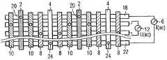
- FIG. 1shows the plan view of a DNA chip with an electrode microsystem in an interdigital structure
- FIG. 2shows the plan view of an electrode microsystem with buried collective lines
- FIG. 3shows the plan view of an electrode microsystem with pointlike sensor electrodes
- FIG. 4shows the section through the electrode microsystem from FIG. 1 along the line IV-IV without (a) and with (b) a reaction layer
- FIG. 5shows the section through the electrode microsystem from FIG. 1 along the line IV-IV with electrodes that lie on ridges and are partly (a) and completely (b) buried,
- FIG. 6shows electrode arrangements in plan view in an interdigital structure (a) and with buried electrode collective lines and plated-through holes (b),
- FIG. 7shows electrode arrangements in cross section with shielding electrodes and differently insulated and buried electrodes (a) to (e),
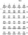
- FIG. 8shows electrode arrangements in cross section with polarization and sensor electrodes lying one above the other in different embodiments (a) to (f),
- FIG. 9shows electrode arrangements in cross section with examples of combinations of the various arrangement techniques (a) to (d), in each case in a basic illustration.
- FIG. 1shows a detail from a DNA chip in plan view, a carrier 14 being indicated.
- the detailshows a spot 1 .
- the microelectrode system thereofexhibits a pair of polarization electrodes 2 and 4 .
- the polarization electrodes 2 and 4are fed by a current source 6 .
- the current source 6generates an AC current that flows through the electrodes 2 and 4 and polarizes an analyte (not specifically illustrated) situated above the electrode arrangement. The analyte thus closes the electric circuit via current source 6 and polarization electrodes 2 and 4 .
- FIG. 1illustrates a pair of sensor electrodes 8 and 10 , which are connected to a high-resistant voltmeter 12 . Since current lines form between the two polarization electrodes 2 and 4 in an electrically conductive analyte applied to the carrier 14 and the electrodes, the sensor electrodes 8 and 10 are in contact with regions of the analyte at a different electrical potential. This potential difference is then indicated at the voltmeter 12 . Since the voltmeter 12 has a high input resistance, however, no appreciable charge transport, that is to say no appreciable current flow, takes place between the analyte and the sensor electrodes 8 and 10 .
- All four electrodes 2 , 4 , 8 and 10 in FIG. 1are arranged in an interdigital structure in FIG. 1 .
- the electrode arrangement illustratedis applied as part of a microchip by using thin-film technology, by way of example, on a carrier 14 , for example silicon with an electrically insulating covering layer (not illustrated), e.g. silicon oxide. All the electrodes are isolated from one another by electrically insulating interspaces 16 .
- the symbolically represented current source 6 and the voltmeter 12are generally embodied as integrated electrical circuits in the carrier 14 e.g. beneath the electrodes.
- the arrangementis illustrated in a manner highly compressed in direction of extent 17 . The same applies to FIGS. 2 , 3 and 6 .
- the embodiment of the invention illustrated in FIG. 2likewise includes a pair of polarization electrodes 2 and 4 and a pair of sensor electrodes 8 and 10 .
- the individual sections of the electrodesare not folded into one another in comblike or meandering fashion as in FIG. 1 .
- Each type of electrodeis embodied in each case as a plurality of elongate strips that are inherently electrically insulated from one another on the chip surface. Thus, two strips each of the polarization electrodes 2 and 4 and four strips each of the sensor electrodes 8 and 10 can be seen.
- each type of electrodeis assigned an electrode collective line.
- the polarization electrode 2is assigned the collective line 18 , by way of example. The two strips of the polarization electrode 2 are therefore connected to the collective line 18 assigned to it with the aid of electrical plated-through holes 20 .
- the collective line 18is electrically insulated from all the other electrodes 4 , 8 and 10 .
- collective lineslie for example buried in the insulating covering layer 36 of the carrier 14 or are at least electrically insulated in some other way both relative to one another and from all the electrodes.
- the second polarization electrode 4is assigned the collective line 22 with corresponding plated-through holes 24 , etc.
- width w and spacing g of the polarization and sensor electrodesare approximately identical in magnitude. This may possibly lead to problems since, in the case of a four-pole measuring method, the sensor electrodes are usually all made substantially smaller than the polarization electrodes.
- FIG. 3An alternative embodiment of sensor electrodes is illustrated in FIG. 3 .
- the sensor electrode 10contains a collective line 26 , which, in accordance with the collective lines 18 and 22 in FIG. 2 , is embodied such that it is buried in the substrate or is sufficiently electrically insulated from e.g. other lines and the analyte.
- the contact between the sensor electrode 10 and the analyteis no longer produced areally as in FIGS. 1 and 2 , but rather only by way of pointlike individual electrodes 28 .
- Each individual electrode 28contains a pointlike electrode head 30 that is connected to the electrode collective line 26 with the aid of an electrical plated-through hole 32 .
- the electrode width w and the electrode spacing gare identical, this measure indicates that the effective electrode area of the sensor electrodes 8 and 10 is substantially smaller in comparison with the area of the polarization electrodes 2 and 4 . It is indicated once again here that in real arrangements the “length” 1 of the electrode is substantially greater than the width w thereof.
- FIG. 4 aillustrates the construction of the carrier 14 comprising the actual, generally monocrystalline, chip carrier, that is to say the substrate 34 , e.g. silicon, and an electrically insulating layer 36 , e.g. silicon oxide.
- the electrodes 2 , 4 , 8 and 10are electrically insulated from one another by the insulating layer 36 and the interspaces 16 .
- the analyte 38which is in contact with the chip surface and the electrodes, is permeated by current lines 40 ending in the polarization electrodes 2 and 4 .
- the current lines 40arise as a result of the polarization current being fed in from the current source 6 into the analyte 38 by way of the polarization electrodes 2 and 4 .
- catcher moleculescan be applied in a very thin layer 42 directly on the chip surface. Methods for this purpose are known sufficiently from the prior art. A target molecule from the analyte 38 can diffuse to the catcher molecule in the layer 42 . It is only in the layer 42 that binding events can thus take place at all and can only be detected there. The detection takes place because in the layer 42 the electrical properties of the medium change on account of the binding events.
- the current and voltage conditions in the analyte 38change and a correspondingly changed voltage is tapped off at the sensor electrodes 8 and 10 .
- a very small proportion of the field-permeated spaceis used for the reaction.
- the alterations of the electrical properties of the analyte that occur in an arrangement of this type and hence the detectable voltages between the sensor electrodes 8 and 10may, if appropriate, lie below the metrologically detectable range of measurement voltages.
- reaction layer 44for example a hydrogel
- catcher moleculesmay be embedded or fixed in its entire volume.
- the reaction layer 44is embodied with a thickness of only approximately 5-10 ⁇ m. Consequently, a chemical reaction can take place between target molecules from the analyte 38 , which can diffuse rapidly into the very thin reaction layer 44 , and the catcher molecules.
- the chemical reaction or alteration of electrical parameters in the reaction layer 44is thus pervaded by a substantially larger range of current lines 40 . Therefore, substantially larger voltages are measured at the voltmeter 12 during a reaction.
- the polarization electrodes 2 and 4lie on electrically insulating ridges 46 at a distance from the surface of the carrier 14 . In specific cases, that is to say for specific combinations of immobilized species and analyte, this may lead to a more favorable field distribution in the analyte space 48 . More favorable means that a largest possible voltage difference between the sensor electrodes 8 and 10 can be measured at the voltmeter 12 .
- the two sensor electrodes 8 and 10are partly buried in the carrier 14 .
- these two electrodesare completely buried and thus directly electrically isolated from the analyte space 48 .
- the degree of burying or the direct electrical isolationmay be more favorable or less favorable for obtaining reliable measurement results at the voltmeter 12 , depending on analyte 38 and immobilized species.
- the selection of ridges 46 as carriers for the polarization electrodes 2 and 4may also be more favorable or less favorable, depending on the situation. A corresponding selection of the structural arrangement can be found experimentally in most cases.
- FIGS. 6 a and 6 bonce again show different embodiments for the configuration and for the connection technique of the different electrodes with regard to the layout and the technologies used in the semiconductor process during chip fabrication.
- FIG. 6 acorresponds to the embodiment in FIG. 1 with regard to the polarization electrodes 2 and 4 .
- the sensor electrodes 8 and 10lie in approximately the same layout as the polarization electrodes 2 and 4 , but below the latter, separated by an electrically insulating intermediate layer, that is to say ridges 46 .
- FIG. 8A section through this arrangement is illustrated in FIG. 8 .
- Such a construction of the DNA chipachieves a very compact construction which permits virtually the smallest possible feature size and distances between one another that can be achieved in the semiconductor process for both types of electrode, that is to say sensor and polarization electrodes 4 and 2 .
- the construction of electrodes arranged one above the otherinfluences the effective ratio between the size of both types of electrode in a similar manner to the configuration shown in FIG. 3 , that is to say that the sensor electrodes 8 and 10 exhibit a small size in relation to the polarization electrodes 2 and 4 .
- FIG. 6 bcorresponds to the arrangement illustrated in FIG. 2 , except that here, too, as in FIG. 6 a, the electrode types are arranged one above the other instead of one beside the other.
- the polarization electrodes 2 and 4again lie on the electrically insulating ridges 46 above the sensor electrodes 10 and 8 , the ridges not being visible from the plan view.
- FIG. 8A section along the line A-A through the arrangement as in FIG. 6 a corresponds to FIG. 8 here, too, except that the electrodes lying one above the other are interchanged.
- the polarization electrodes 2 and 4lie above the sensor electrodes 10 and 8 , respectively.
- each sensor electrode 8 and 10is respectively assigned two shielding electrodes 50 and 52 .
- buffer amplifiers 54the respective electrical potential of the sensor electrodes 8 and 10 is held in electrically active fashion at the shielding electrodes 50 and 52 .
- the parasitic capacitances 56 , 58 and 60which are effective in the case of shielding electrodes being absent—between sensor electrodes 8 and 10 and polarization electrodes 2 and 4 become partly electrically ineffective by virtue of this measure, as is readily apparent from an electrical equivalent circuit diagram (not illustrated) of the arrangement. This is because the parasitic capacitances 62 to 74 form with shielding electrodes present.
- the buffer amplifiers 54may be realized with the aid of semiconductor technology. This is directly in the carrier 14 beneath the electrode arrangement. This shortens signal paths, keeps additional capacitances as small as possible and, consequently, has a favorable influence on the frequency properties of the entire measuring arrangement.
- the various embodiments illustrated in FIG. 7 for arrangement of the individual electrodesdiffer by the fact that one or more electrodes are directly electrically isolated from the analyte or are completely or partially buried in the substrate.
- the direct electrical isolationis effected, as in FIG. 7 a, e.g. by oxidation of an additional oxide layer above the electrodes or by burying the electrodes, as carried out in FIG. 7 e for all of the electrodes involved.
- FIG. 7too, different combinations between the alternatives illustrated are again conceivable. These may be adapted by way of simulations or experimentally to the requirements of a specific measurement or configuration of the chip.
- FIG. 8also illustrates a wide variety of combinations of the arrangement of sensor and polarization electrodes. While the polarization electrodes always rest on ridges above the carrier, the sensor electrodes are in each case arranged beneath or within the ridges. These measures make it possible to achieve an extremely compact design of the DNA chip since the spacings between the electrode types can be minimized.
- FIG. 9shows configurations of electrodes corresponding to FIGS. 8 , here one or more shielding electrodes additionally being provided between sensor electrodes among one another or between sensor and polarization electrodes.
Landscapes
- Health & Medical Sciences (AREA)
- Immunology (AREA)
- Life Sciences & Earth Sciences (AREA)
- Engineering & Computer Science (AREA)
- Molecular Biology (AREA)
- Biomedical Technology (AREA)
- Chemical & Material Sciences (AREA)
- Hematology (AREA)
- Urology & Nephrology (AREA)
- Biotechnology (AREA)
- Biochemistry (AREA)
- Cell Biology (AREA)
- Food Science & Technology (AREA)
- Medicinal Chemistry (AREA)
- Physics & Mathematics (AREA)
- Analytical Chemistry (AREA)
- Microbiology (AREA)
- General Health & Medical Sciences (AREA)
- General Physics & Mathematics (AREA)
- Pathology (AREA)
- Investigating Or Analyzing Materials By The Use Of Electric Means (AREA)
- Apparatus Associated With Microorganisms And Enzymes (AREA)
- Investigating Or Analysing Biological Materials (AREA)
Abstract
Description
Claims (18)
Applications Claiming Priority (3)
| Application Number | Priority Date | Filing Date | Title |
|---|---|---|---|
| DE10259820ADE10259820B4 (en) | 2002-12-19 | 2002-12-19 | DNA chip |
| DE10259820.7 | 2002-12-19 | ||
| PCT/DE2003/004127WO2004057334A1 (en) | 2002-12-19 | 2003-12-15 | Dna chip comprising a microarray made of an microelectrode system |
Publications (2)
| Publication Number | Publication Date |
|---|---|
| US20060216813A1 US20060216813A1 (en) | 2006-09-28 |
| US7572624B2true US7572624B2 (en) | 2009-08-11 |
Family
ID=32404018
Family Applications (1)
| Application Number | Title | Priority Date | Filing Date |
|---|---|---|---|
| US10/539,817Expired - LifetimeUS7572624B2 (en) | 2002-12-19 | 2003-12-15 | DNA chip comprising a microarray made of an microelectrode system |
Country Status (7)
| Country | Link |
|---|---|
| US (1) | US7572624B2 (en) |
| EP (1) | EP1573327B1 (en) |
| JP (1) | JP4287819B2 (en) |
| CA (1) | CA2510720C (en) |
| DE (1) | DE10259820B4 (en) |
| DK (1) | DK1573327T3 (en) |
| WO (1) | WO2004057334A1 (en) |
Cited By (8)
| Publication number | Priority date | Publication date | Assignee | Title |
|---|---|---|---|---|
| US20100148307A1 (en)* | 2004-10-22 | 2010-06-17 | Nec Electronics Corporation | Semiconductor device including metal-insulator-metal capacitor arrangement |
| US9759711B2 (en) | 2013-02-05 | 2017-09-12 | Genia Technologies, Inc. | Nanopore arrays |
| US9869655B2 (en) | 2011-01-24 | 2018-01-16 | Genia Technologies, Inc. | System for detecting electrical properties of a molecular complex |
| US9983163B2 (en) | 2013-04-30 | 2018-05-29 | Board Of Regents, The University Of Texas System | Integrated electro-analytical biosensor array |
| US10036725B2 (en) | 2013-10-17 | 2018-07-31 | Genia Technologies, Inc. | Non-faradaic, capacitively coupled measurement in a nanopore cell array |
| US10343350B2 (en) | 2010-02-08 | 2019-07-09 | Genia Technologies, Inc. | Systems and methods for forming a nanopore in a lipid bilayer |
| US10371692B2 (en) | 2010-02-08 | 2019-08-06 | Genia Technologies, Inc. | Systems for forming a nanopore in a lipid bilayer |
| US10724987B2 (en) | 2012-02-27 | 2020-07-28 | Roche Sequencing Solutions, Inc. | Sensor circuit for controlling, detecting, and measuring a molecular complex |
Families Citing this family (6)
| Publication number | Priority date | Publication date | Assignee | Title |
|---|---|---|---|---|
| DE102004045210A1 (en) | 2004-09-17 | 2006-04-06 | Infineon Technologies Ag | Sensor arrangement and method for determining a sensor event |
| KR100969671B1 (en)* | 2008-03-28 | 2010-07-14 | 디지탈 지노믹스(주) | High sensitivity biosensor, biochip comprising same and method for manufacturing same |
| WO2009132667A1 (en)* | 2008-04-30 | 2009-11-05 | Micronas Gmbh | Method for verifying and/or determining the concentration of a ligand |
| JP5786295B2 (en)* | 2010-06-22 | 2015-09-30 | ソニー株式会社 | Nucleic acid isothermal amplification microchip, method for producing the same, and nucleic acid isothermal amplification method |
| US9140658B1 (en)* | 2012-01-06 | 2015-09-22 | Enuresis Solutions Llc | Fluid detection device |
| CN106497774A (en)* | 2017-01-03 | 2017-03-15 | 京东方科技集团股份有限公司 | Gene sequencing chip, gene sequencing equipment and gene order surveying method |
Citations (20)
| Publication number | Priority date | Publication date | Assignee | Title |
|---|---|---|---|---|
| JPS55138397A (en) | 1979-04-13 | 1980-10-29 | Fujisawa Pharmaceut Co Ltd | Method of measurement of bacterium growth rate and device therefor |
| WO1990012314A1 (en) | 1989-04-04 | 1990-10-18 | Gerald Urban | Micro-multi-electrode arrangement |
| JPH07508831A (en) | 1992-04-23 | 1995-09-28 | マサチューセッツ・インスティチュート・オブ・テクノロジー | Optical and electrical methods and devices for molecular detection |
| JP2504069B2 (en) | 1987-09-10 | 1996-06-05 | いすゞ自動車株式会社 | Control device for turbocharger with rotating electric machine |
| US5567301A (en)* | 1995-03-01 | 1996-10-22 | Illinois Institute Of Technology | Antibody covalently bound film immunobiosensor |
| JP2590728B2 (en) | 1994-04-21 | 1997-03-12 | 日本電気株式会社 | Selective growth method of compound semiconductor |
| DE19610115A1 (en) | 1996-03-14 | 1997-09-18 | Fraunhofer Ges Forschung | Detection of molecules and molecular complexes |
| WO1998019153A1 (en) | 1996-10-26 | 1998-05-07 | The Victoria University Of Manchester | Sensor employing impedance measurements |
| WO2000062047A1 (en) | 1999-04-14 | 2000-10-19 | Fraunhofer-Gesellschaft zur Förderung der angewandten Forschung e.V. | Electric sensor array |
| WO2000063682A2 (en) | 1999-04-17 | 2000-10-26 | Cardselect Systems Ltd | Sensor apparatus and method for detecting and identifying fluids |
| US6169394B1 (en)* | 1998-09-18 | 2001-01-02 | University Of The Utah Research Foundation | Electrical detector for micro-analysis systems |
| WO2001044805A2 (en) | 1999-12-15 | 2001-06-21 | Nanogen, Inc. | Permeation layer attachment chemistry and method |
| DE10015816A1 (en) | 2000-03-30 | 2001-10-18 | Infineon Technologies Ag | Biosensor chip |
| WO2001079828A1 (en) | 2000-04-14 | 2001-10-25 | Nanotec Solution | Device and method for determining characteristics of a biomass |
| WO2001083674A1 (en)* | 2000-05-03 | 2001-11-08 | Gau Jen Jr | Biological identification system with integrated sensor chip |
| WO2002042759A1 (en) | 2000-11-24 | 2002-05-30 | Siemens Aktiengesellschaft | Method for electrochemical analysis, corresponding configurations and the use thereof |
| US20020172969A1 (en)* | 1996-11-20 | 2002-11-21 | The Regents Of The University Of Michigan | Chip-based isothermal amplification devices and methods |
| US6485703B1 (en)* | 1998-07-31 | 2002-11-26 | The Texas A&M University System | Compositions and methods for analyte detection |
| US20040197899A1 (en)* | 2000-04-17 | 2004-10-07 | Purdue Research Foundation | Biosensor and related method |
| US7087148B1 (en)* | 1998-06-23 | 2006-08-08 | Clinical Micro Sensors, Inc. | Binding acceleration techniques for the detection of analytes |
- 2002
- 2002-12-19DEDE10259820Apatent/DE10259820B4/ennot_activeExpired - Lifetime
- 2003
- 2003-12-15JPJP2004561039Apatent/JP4287819B2/ennot_activeExpired - Fee Related
- 2003-12-15WOPCT/DE2003/004127patent/WO2004057334A1/enactiveApplication Filing
- 2003-12-15USUS10/539,817patent/US7572624B2/ennot_activeExpired - Lifetime
- 2003-12-15CACA2510720Apatent/CA2510720C/ennot_activeExpired - Lifetime
- 2003-12-15DKDK03795750.3Tpatent/DK1573327T3/enactive
- 2003-12-15EPEP03795750.3Apatent/EP1573327B1/ennot_activeExpired - Lifetime
Patent Citations (27)
| Publication number | Priority date | Publication date | Assignee | Title |
|---|---|---|---|---|
| JPS55138397A (en) | 1979-04-13 | 1980-10-29 | Fujisawa Pharmaceut Co Ltd | Method of measurement of bacterium growth rate and device therefor |
| JP2504069B2 (en) | 1987-09-10 | 1996-06-05 | いすゞ自動車株式会社 | Control device for turbocharger with rotating electric machine |
| WO1990012314A1 (en) | 1989-04-04 | 1990-10-18 | Gerald Urban | Micro-multi-electrode arrangement |
| JPH07508831A (en) | 1992-04-23 | 1995-09-28 | マサチューセッツ・インスティチュート・オブ・テクノロジー | Optical and electrical methods and devices for molecular detection |
| US5704975A (en) | 1994-04-21 | 1998-01-06 | Nec Corporation | Selective crystal growth method of compound semiconductor |
| JP2590728B2 (en) | 1994-04-21 | 1997-03-12 | 日本電気株式会社 | Selective growth method of compound semiconductor |
| US5567301A (en)* | 1995-03-01 | 1996-10-22 | Illinois Institute Of Technology | Antibody covalently bound film immunobiosensor |
| US20020028441A1 (en) | 1996-03-14 | 2002-03-07 | Rainer Hintsche | Detection of molecules and molecule complexes |
| DE19610115A1 (en) | 1996-03-14 | 1997-09-18 | Fraunhofer Ges Forschung | Detection of molecules and molecular complexes |
| WO1998019153A1 (en) | 1996-10-26 | 1998-05-07 | The Victoria University Of Manchester | Sensor employing impedance measurements |
| US20020172969A1 (en)* | 1996-11-20 | 2002-11-21 | The Regents Of The University Of Michigan | Chip-based isothermal amplification devices and methods |
| US7087148B1 (en)* | 1998-06-23 | 2006-08-08 | Clinical Micro Sensors, Inc. | Binding acceleration techniques for the detection of analytes |
| US6485703B1 (en)* | 1998-07-31 | 2002-11-26 | The Texas A&M University System | Compositions and methods for analyte detection |
| US6169394B1 (en)* | 1998-09-18 | 2001-01-02 | University Of The Utah Research Foundation | Electrical detector for micro-analysis systems |
| US7208077B1 (en)* | 1999-04-14 | 2007-04-24 | Fraunhofer-Gesellschaft Zur Foerderung Der Angewandten Forschung E.V. | Sensor arrangement with electrically controllable arrays |
| WO2000062047A1 (en) | 1999-04-14 | 2000-10-19 | Fraunhofer-Gesellschaft zur Förderung der angewandten Forschung e.V. | Electric sensor array |
| WO2000062048A2 (en)* | 1999-04-14 | 2000-10-19 | Fraunhofer-Gesellschaft Zur Foerderung Der Angewandten Forschung E.V. | Sensor arrangement with electrically controllable arrays |
| WO2000063682A2 (en) | 1999-04-17 | 2000-10-26 | Cardselect Systems Ltd | Sensor apparatus and method for detecting and identifying fluids |
| US20020015993A1 (en) | 1999-12-15 | 2002-02-07 | John Havens R. | Permeation layer attachment chemistry and method |
| WO2001044805A2 (en) | 1999-12-15 | 2001-06-21 | Nanogen, Inc. | Permeation layer attachment chemistry and method |
| DE10015816A1 (en) | 2000-03-30 | 2001-10-18 | Infineon Technologies Ag | Biosensor chip |
| US20030070942A1 (en) | 2000-04-14 | 2003-04-17 | Frederic Ossart | Device and method for determining characteristics of a biomass |
| WO2001079828A1 (en) | 2000-04-14 | 2001-10-25 | Nanotec Solution | Device and method for determining characteristics of a biomass |
| US20040197899A1 (en)* | 2000-04-17 | 2004-10-07 | Purdue Research Foundation | Biosensor and related method |
| WO2001083674A1 (en)* | 2000-05-03 | 2001-11-08 | Gau Jen Jr | Biological identification system with integrated sensor chip |
| WO2002042759A1 (en) | 2000-11-24 | 2002-05-30 | Siemens Aktiengesellschaft | Method for electrochemical analysis, corresponding configurations and the use thereof |
| US20040063152A1 (en) | 2000-11-24 | 2004-04-01 | Walter Gumbrecht | Method for electrochemical analysis, corresponding configurations and the use thereof |
Non-Patent Citations (6)
| Title |
|---|
| German Office Action Dated Mar. 24, 2005. |
| German Translation Aid. Date Unknown. |
| International Search Reports (English and German) dated May 5, 2004. |
| Japanese Office Action mailed on Aug. 7, 2008 for corresponding Japanese Patent Application No. 2004-561039. |
| M. Paeschke et al.: Voltammetric Multichannel Measurements Using Silicon Fabricated Microelectrode Arrays, Electroanalysis 8, No. 10, S. 891-899, 1996. |
| R. Hintsche et al.: Microbiosensors Using electrodes Made in Si-Technology, Frontiers in Biosensorics, Fundamental Aspects, edited by F.W. Scheller et al., Dirk Hauser Verlag, Basel, S. 267-283, 1997. |
Cited By (20)
| Publication number | Priority date | Publication date | Assignee | Title |
|---|---|---|---|---|
| US7986026B2 (en)* | 2004-10-22 | 2011-07-26 | Renesas Electronics Corporation | Semiconductor device including metal-insulator-metal capacitor arrangement |
| US8378454B2 (en) | 2004-10-22 | 2013-02-19 | Renesas Electronics Corporation | Semiconductor device including metal-insulator-metal capacitor arrangement |
| US20100148307A1 (en)* | 2004-10-22 | 2010-06-17 | Nec Electronics Corporation | Semiconductor device including metal-insulator-metal capacitor arrangement |
| US10456993B2 (en) | 2010-02-08 | 2019-10-29 | Roche Sequencing Solutions, Inc. | Systems and methods for forming a nanopore in a lipid bilayer |
| US10371692B2 (en) | 2010-02-08 | 2019-08-06 | Genia Technologies, Inc. | Systems for forming a nanopore in a lipid bilayer |
| US10343350B2 (en) | 2010-02-08 | 2019-07-09 | Genia Technologies, Inc. | Systems and methods for forming a nanopore in a lipid bilayer |
| US11027502B2 (en) | 2010-02-08 | 2021-06-08 | Roche Sequencing Solutions, Inc. | Systems and methods for forming a nanopore in a lipid bilayer |
| US10926486B2 (en) | 2010-02-08 | 2021-02-23 | Roche Sequencing Solutions, Inc. | Systems and methods for forming a nanopore in a lipid bilayer |
| US10330633B2 (en) | 2011-01-24 | 2019-06-25 | Genia Technologies, Inc. | System for communicating information from an array of sensors |
| US10156541B2 (en) | 2011-01-24 | 2018-12-18 | Genia Technologies, Inc. | System for detecting electrical properties of a molecular complex |
| US9869655B2 (en) | 2011-01-24 | 2018-01-16 | Genia Technologies, Inc. | System for detecting electrical properties of a molecular complex |
| US11275052B2 (en) | 2012-02-27 | 2022-03-15 | Roche Sequencing Solutions, Inc. | Sensor circuit for controlling, detecting, and measuring a molecular complex |
| US10724987B2 (en) | 2012-02-27 | 2020-07-28 | Roche Sequencing Solutions, Inc. | Sensor circuit for controlling, detecting, and measuring a molecular complex |
| US10809244B2 (en) | 2013-02-05 | 2020-10-20 | Roche Sequencing Solutions, Inc. | Nanopore arrays |
| US10012637B2 (en) | 2013-02-05 | 2018-07-03 | Genia Technologies, Inc. | Nanopore arrays |
| US9759711B2 (en) | 2013-02-05 | 2017-09-12 | Genia Technologies, Inc. | Nanopore arrays |
| US9983163B2 (en) | 2013-04-30 | 2018-05-29 | Board Of Regents, The University Of Texas System | Integrated electro-analytical biosensor array |
| US11579111B2 (en) | 2013-04-30 | 2023-02-14 | Board Of Regents, The University Of Texas System | Integrated electro-analytical biosensor array |
| US10393700B2 (en) | 2013-10-17 | 2019-08-27 | Roche Sequencing Solutions, Inc. | Non-faradaic, capacitively coupled measurement in a nanopore cell array |
| US10036725B2 (en) | 2013-10-17 | 2018-07-31 | Genia Technologies, Inc. | Non-faradaic, capacitively coupled measurement in a nanopore cell array |
Also Published As
| Publication number | Publication date |
|---|---|
| EP1573327B1 (en) | 2013-10-16 |
| EP1573327A1 (en) | 2005-09-14 |
| DK1573327T3 (en) | 2013-12-16 |
| DE10259820B4 (en) | 2006-05-24 |
| CA2510720C (en) | 2012-02-14 |
| WO2004057334A1 (en) | 2004-07-08 |
| JP4287819B2 (en) | 2009-07-01 |
| DE10259820A1 (en) | 2004-07-01 |
| CA2510720A1 (en) | 2004-07-08 |
| JP2006510881A (en) | 2006-03-30 |
| US20060216813A1 (en) | 2006-09-28 |
Similar Documents
| Publication | Publication Date | Title |
|---|---|---|
| US7572624B2 (en) | DNA chip comprising a microarray made of an microelectrode system | |
| US10274455B2 (en) | Nanoelectronic sensor pixel | |
| US9435802B2 (en) | Sensor, a sensor array, and a method of operating a sensor | |
| EP1516174B1 (en) | Method and device for high sensitivity detection of the presence of dna and other probes | |
| JP3969702B2 (en) | Sensor cell, sensor, sample identification method, chemical sensor, fingerprint recognition apparatus, biosensor operation method, and fingerprint recognition apparatus operation method | |
| US10059982B2 (en) | Nano-sensor array | |
| JP3874772B2 (en) | Biologically related substance measuring apparatus and measuring method | |
| US20170103952A1 (en) | Noise shielding techniques for ultra low current measurements in biochemical applications | |
| Zhang et al. | Surface functionalization of ion-sensitive floating-gate field-effect transistors with organic electronics | |
| JP2009534641A (en) | Magnetic particle measuring device and method | |
| US20140026642A1 (en) | Capacitive sensor comprising differing unit cell structures | |
| US20080036444A1 (en) | Sensor Arrangement and Method for Detecting a Sensor Event | |
| IL169271A (en) | Devices and method for direct electrical detection of molecules and molecule-molecule interactions | |
| US12066395B2 (en) | Sensor for the impedance measurements of the biological or chemical factor sample and the method for the detection of the biological or chemical factor in the sample using such a sensor | |
| US20060226030A1 (en) | Capacitative biosensor element and method for detecting hybridization events | |
| US6922081B2 (en) | Electronic circuit, sensor arrangement and method for processing a sensor signal | |
| CN106959330A (en) | Integrated ion sensor and method | |
| US7670557B2 (en) | Planar sensor arrangement, sensor array and method for the production of a planar-sensor arrangement | |
| US8617382B2 (en) | Process and device for emulating a counter-electrode in a monolithically integrated electrochemical analysis system | |
| de Araujo et al. | Detection and characterization of biological cells by impedance spectroscopy | |
| US12270777B2 (en) | 2D microfluidic structure | |
| TW202528732A (en) | Sensing device with multiple sensing areas and sensing method by multiple sensing areas |
Legal Events
| Date | Code | Title | Description |
|---|---|---|---|
| AS | Assignment | Owner name:SIEMENS AKTIENGESELLSCHAFT, GERMANY Free format text:ASSIGNMENT OF ASSIGNORS INTEREST;ASSIGNORS:SCHIENLE, MEINARD;THEWES, ROLAND;GUMBRECHT, WALTER;AND OTHERS;REEL/FRAME:017751/0671;SIGNING DATES FROM 20050610 TO 20060125 Owner name:INFINEON TECHNOLOGIES AG, GERMANY Free format text:ASSIGNMENT OF ASSIGNORS INTEREST;ASSIGNORS:SCHIENLE, MEINARD;THEWES, ROLAND;GUMBRECHT, WALTER;AND OTHERS;REEL/FRAME:017751/0671;SIGNING DATES FROM 20050610 TO 20060125 | |
| STCF | Information on status: patent grant | Free format text:PATENTED CASE | |
| AS | Assignment | Owner name:SIEMENS AKTIENGESELLSCHAFT, GERMANY Free format text:ASSIGNMENT OF ASSIGNORS INTEREST;ASSIGNOR:INFINEON TECHNOLOGIES AG;REEL/FRAME:023565/0819 Effective date:20091119 | |
| FPAY | Fee payment | Year of fee payment:4 | |
| FEPP | Fee payment procedure | Free format text:PAYOR NUMBER ASSIGNED (ORIGINAL EVENT CODE: ASPN); ENTITY STATUS OF PATENT OWNER: LARGE ENTITY | |
| AS | Assignment | Owner name:BOEHRINGER INGELHEIM VETMEDICA GMBH, GERMANY Free format text:ASSIGNMENT OF ASSIGNORS INTEREST;ASSIGNOR:SIEMENS AG;REEL/FRAME:033190/0899 Effective date:20140507 | |
| FPAY | Fee payment | Year of fee payment:8 | |
| MAFP | Maintenance fee payment | Free format text:PAYMENT OF MAINTENANCE FEE, 12TH YEAR, LARGE ENTITY (ORIGINAL EVENT CODE: M1553); ENTITY STATUS OF PATENT OWNER: LARGE ENTITY Year of fee payment:12 |