US7572367B2 - Liquid filtration device - Google Patents
Liquid filtration deviceDownload PDFInfo
- Publication number
- US7572367B2 US7572367B2US12/221,309US22130908AUS7572367B2US 7572367 B2US7572367 B2US 7572367B2US 22130908 AUS22130908 AUS 22130908AUS 7572367 B2US7572367 B2US 7572367B2
- Authority
- US
- United States
- Prior art keywords
- fluid
- fluid channel
- bowl
- vent
- cap
- Prior art date
- Legal status (The legal status is an assumption and is not a legal conclusion. Google has not performed a legal analysis and makes no representation as to the accuracy of the status listed.)
- Expired - Fee Related
Links
- 238000001914filtrationMethods0.000titleclaimsabstractdescription57
- 239000007788liquidSubstances0.000titleclaimsabstractdescription21
- 239000012530fluidSubstances0.000claimsabstractdescription271
- 238000010926purgeMethods0.000claimsabstractdescription7
- 239000012528membraneSubstances0.000claimsdescription13
- 230000037361pathwayEffects0.000claimsdescription6
- 238000010408sweepingMethods0.000claimsdescription5
- 238000007872degassingMethods0.000claimsdescription3
- 230000008878couplingEffects0.000claims3
- 238000010168coupling processMethods0.000claims3
- 238000005859coupling reactionMethods0.000claims3
- 238000000034methodMethods0.000abstractdescription38
- 230000008569processEffects0.000abstractdescription29
- 238000013022ventingMethods0.000description25
- 238000005516engineering processMethods0.000description7
- 239000000758substrateSubstances0.000description7
- 239000002699waste materialSubstances0.000description7
- 238000011144upstream manufacturingMethods0.000description6
- 230000008901benefitEffects0.000description5
- 238000004891communicationMethods0.000description5
- 230000007547defectEffects0.000description4
- 238000013461designMethods0.000description4
- 239000011148porous materialSubstances0.000description4
- 230000015572biosynthetic processEffects0.000description3
- 230000001276controlling effectEffects0.000description2
- 239000007863gel particleSubstances0.000description2
- 230000003287optical effectEffects0.000description2
- 229920006395saturated elastomerPolymers0.000description2
- 239000004065semiconductorSubstances0.000description2
- 101100022495African swine fever virus (isolate Tick/Malawi/Lil 20-1/1983) Mal-109 geneProteins0.000description1
- 101100049229African swine fever virus (isolate Tick/Malawi/Lil 20-1/1983) Mal-111 geneProteins0.000description1
- 230000003667anti-reflective effectEffects0.000description1
- 230000004888barrier functionEffects0.000description1
- POIUWJQBRNEFGX-XAMSXPGMSA-NcathelicidinChemical compoundC([C@@H](C(=O)N[C@@H](CCCNC(N)=N)C(=O)N[C@@H](CCCCN)C(=O)N[C@@H](CO)C(=O)N[C@@H](CCCCN)C(=O)N[C@@H](CCC(O)=O)C(=O)N[C@@H](CCCCN)C(=O)N[C@@H]([C@@H](C)CC)C(=O)NCC(=O)N[C@@H](CCCCN)C(=O)N[C@@H](CCC(O)=O)C(=O)N[C@@H](CC=1C=CC=CC=1)C(=O)N[C@@H](CCCCN)C(=O)N[C@@H](CCCNC(N)=N)C(=O)N[C@@H]([C@@H](C)CC)C(=O)N[C@@H](C(C)C)C(=O)N[C@@H](CCC(N)=O)C(=O)N[C@@H](CCCNC(N)=N)C(=O)N[C@@H]([C@@H](C)CC)C(=O)N[C@@H](CCCCN)C(=O)N[C@@H](CC(O)=O)C(=O)N[C@@H](CC=1C=CC=CC=1)C(=O)N[C@@H](CC(C)C)C(=O)N[C@@H](CCCNC(N)=N)C(=O)N[C@@H](CC(N)=O)C(=O)N[C@@H](CC(C)C)C(=O)N[C@@H](C(C)C)C(=O)N1[C@@H](CCC1)C(=O)N[C@@H](CCCNC(N)=N)C(=O)N[C@@H]([C@@H](C)O)C(=O)N[C@@H](CCC(O)=O)C(=O)N[C@@H](CO)C(O)=O)NC(=O)[C@H](CC=1C=CC=CC=1)NC(=O)[C@H](CC(O)=O)NC(=O)CNC(=O)[C@H](CC(C)C)NC(=O)[C@@H](N)CC(C)C)C1=CC=CC=C1POIUWJQBRNEFGX-XAMSXPGMSA-N0.000description1
- 230000008859changeEffects0.000description1
- 230000003750conditioning effectEffects0.000description1
- 238000000151depositionMethods0.000description1
- 238000010586diagramMethods0.000description1
- 239000003989dielectric materialSubstances0.000description1
- 238000010438heat treatmentMethods0.000description1
- 230000006872improvementEffects0.000description1
- 238000010348incorporationMethods0.000description1
- 239000000463materialSubstances0.000description1
- 230000007246mechanismEffects0.000description1
- 238000000206photolithographyMethods0.000description1
- 229920002120photoresistant polymerPolymers0.000description1
- 230000001105regulatory effectEffects0.000description1
- 230000000630rising effectEffects0.000description1
- 238000000926separation methodMethods0.000description1
- 238000000935solvent evaporationMethods0.000description1
- 239000000126substanceSubstances0.000description1
- 230000001960triggered effectEffects0.000description1
Images


Classifications
- B—PERFORMING OPERATIONS; TRANSPORTING
- B01—PHYSICAL OR CHEMICAL PROCESSES OR APPARATUS IN GENERAL
- B01D—SEPARATION
- B01D65/00—Accessories or auxiliary operations, in general, for separation processes or apparatus using semi-permeable membranes
- B—PERFORMING OPERATIONS; TRANSPORTING
- B01—PHYSICAL OR CHEMICAL PROCESSES OR APPARATUS IN GENERAL
- B01D—SEPARATION
- B01D19/00—Degasification of liquids
- B—PERFORMING OPERATIONS; TRANSPORTING
- B01—PHYSICAL OR CHEMICAL PROCESSES OR APPARATUS IN GENERAL
- B01D—SEPARATION
- B01D19/00—Degasification of liquids
- B01D19/0031—Degasification of liquids by filtration
- B—PERFORMING OPERATIONS; TRANSPORTING
- B01—PHYSICAL OR CHEMICAL PROCESSES OR APPARATUS IN GENERAL
- B01D—SEPARATION
- B01D19/00—Degasification of liquids
- B01D19/0042—Degasification of liquids modifying the liquid flow
- B—PERFORMING OPERATIONS; TRANSPORTING
- B01—PHYSICAL OR CHEMICAL PROCESSES OR APPARATUS IN GENERAL
- B01D—SEPARATION
- B01D29/00—Filters with filtering elements stationary during filtration, e.g. pressure or suction filters, not covered by groups B01D24/00 - B01D27/00; Filtering elements therefor
- B01D29/11—Filters with filtering elements stationary during filtration, e.g. pressure or suction filters, not covered by groups B01D24/00 - B01D27/00; Filtering elements therefor with bag, cage, hose, tube, sleeve or like filtering elements
- B01D29/13—Supported filter elements
- B01D29/15—Supported filter elements arranged for inward flow filtration
- B—PERFORMING OPERATIONS; TRANSPORTING
- B01—PHYSICAL OR CHEMICAL PROCESSES OR APPARATUS IN GENERAL
- B01D—SEPARATION
- B01D29/00—Filters with filtering elements stationary during filtration, e.g. pressure or suction filters, not covered by groups B01D24/00 - B01D27/00; Filtering elements therefor
- B01D29/88—Filters with filtering elements stationary during filtration, e.g. pressure or suction filters, not covered by groups B01D24/00 - B01D27/00; Filtering elements therefor having feed or discharge devices
- B01D29/90—Filters with filtering elements stationary during filtration, e.g. pressure or suction filters, not covered by groups B01D24/00 - B01D27/00; Filtering elements therefor having feed or discharge devices for feeding
- B01D29/902—Filters with filtering elements stationary during filtration, e.g. pressure or suction filters, not covered by groups B01D24/00 - B01D27/00; Filtering elements therefor having feed or discharge devices for feeding containing fixed liquid displacement elements or cores
- B—PERFORMING OPERATIONS; TRANSPORTING
- B01—PHYSICAL OR CHEMICAL PROCESSES OR APPARATUS IN GENERAL
- B01D—SEPARATION
- B01D36/00—Filter circuits or combinations of filters with other separating devices
- B—PERFORMING OPERATIONS; TRANSPORTING
- B01—PHYSICAL OR CHEMICAL PROCESSES OR APPARATUS IN GENERAL
- B01D—SEPARATION
- B01D36/00—Filter circuits or combinations of filters with other separating devices
- B01D36/001—Filters in combination with devices for the removal of gas, air purge systems
- B—PERFORMING OPERATIONS; TRANSPORTING
- B01—PHYSICAL OR CHEMICAL PROCESSES OR APPARATUS IN GENERAL
- B01D—SEPARATION
- B01D61/00—Processes of separation using semi-permeable membranes, e.g. dialysis, osmosis or ultrafiltration; Apparatus, accessories or auxiliary operations specially adapted therefor
- B01D61/14—Ultrafiltration; Microfiltration
- B01D61/20—Accessories; Auxiliary operations
- B—PERFORMING OPERATIONS; TRANSPORTING
- B01—PHYSICAL OR CHEMICAL PROCESSES OR APPARATUS IN GENERAL
- B01D—SEPARATION
- B01D63/00—Apparatus in general for separation processes using semi-permeable membranes
- B01D63/06—Tubular membrane modules
- B01D63/067—Tubular membrane modules with pleated membranes
- B—PERFORMING OPERATIONS; TRANSPORTING
- B01—PHYSICAL OR CHEMICAL PROCESSES OR APPARATUS IN GENERAL
- B01D—SEPARATION
- B01D2201/00—Details relating to filtering apparatus
- B01D2201/30—Filter housing constructions
- B01D2201/301—Details of removable closures, lids, caps, filter heads
- B01D2201/302—Details of removable closures, lids, caps, filter heads having inlet or outlet ports
- B—PERFORMING OPERATIONS; TRANSPORTING
- B01—PHYSICAL OR CHEMICAL PROCESSES OR APPARATUS IN GENERAL
- B01D—SEPARATION
- B01D2313/00—Details relating to membrane modules or apparatus
- B01D2313/08—Flow guidance means within the module or the apparatus
- B—PERFORMING OPERATIONS; TRANSPORTING
- B01—PHYSICAL OR CHEMICAL PROCESSES OR APPARATUS IN GENERAL
- B01D—SEPARATION
- B01D2313/00—Details relating to membrane modules or apparatus
- B01D2313/16—Specific vents
Definitions
- the IMPACT® LVHD filtersold by Mykrolis Corporation of Bedford, Mass., has a low hold up volume which is very advantageous due to the high cost of the process fluids principally filtered by the device: photoresist, dielectrics, anti-reflectives and optical disc materials.
- the IMPACT LHVD filterprovides superior filtration to prevent debris in the process fluid from being deposited onto the substrate and from causing defects.
- FIG. 1provides a device that uses three independent connections, a vent 12 , a feed 14 , and an outlet 16 , that can interface with either a stand alone manifold or directly to a dispense system such as the RGENTM or IntelliGen® dispense systems that are manufactured by Mykrolis Corporation.
- the process fluidenters through the inlet port 14 and flows through the inlet tube 24 to the housing bottom 25 .
- the process fluidthen flows through the vertical membrane filter 26 to the outlet port 16 , where the purified fluid is directed back to the manifold or dispense system.
- the vent port 12allows bubbles that accumulate on the upstream side of the filter to exit the housing 22 .
- the top surface of the housing cap 18is set at an angle directed up to the vent port 12 . This allows air bubbles to gradually rise to the highest point in the housing 20 and to exit the housing 22 .
- the design and performance of the IMPACT LHVD filteris much improved over other filtration devices, it is also not fully optimized for bubble venting.
- bubble-laden fluidis forced to the bottom of the device to sweep the bottom with fluid to prevent fluid stagnation at the bottom and the formation of gel particles. Therefore, any entrained bubbles must then rise to the vent. Again, the slowly rising bubbles from the bottom will require more time and chemical to purge them from the device.
- TSTTwo Stage Technology
- bubble ventingis still not optimized as the venting process release not just bubbles but a bubble saturated fluid stream. Since bubbles do not rise quickly in many process fluids, the motion of the fluid toward the vent is required to remove the bubbles (effectively, the bubbles are carried along by the fluid stream). In addition, the smaller the bubbles to be removed, the more fluid that is ejected in the stream.
- liquid filtration devicewherein bubble removal from the liquid being filtered be initiated prior to filtration so that the gas bubbles removed are positioned near the vent, thereby facilitating gas bubble removal from the liquid being filtered. Also, it would be desirable to have the system to provide a means for automatic venting of a liquid filtration device that minimizes the amount of fluid loss.
- the present inventionprovides a device that eliminates gas bubbles from a fluid by using the fluid's velocity within the device, coupled with specific flow channels, to remove pockets of gas from liquid filtration devices.
- the properly designed flow pathsdirect fluid into locations where gas bubbles will most likely collect.
- the present inventionprovides a device and method for eliminating gas bubbles from a liquid within a housing having a housing cover that will allow for faster and more efficient removal of entrained bubbles.
- the new device and methoduses a portion of the fluid's velocity at the device inlet to sweep around the underside of a flange of a filter cartridge within the device. This will force gas bubbles within the fluid to rise above the filter membrane and adjacent the inside surface of the housing cover.
- the liquid streams positioned beneath the filter cartridge's flangethen converge to the inside surface of the housing cover and proceed to force gas bubbles from the fluid to proceed toward the vent port of the device.
- the present inventionprovides a method for effecting automatic venting of bubbles from the fluid being filtered.
- FIG. 1is a representation of the prior art, a sectional view of an IMPACT LHVD filter.
- FIGS. 2 a and 2 bare cross-sectional views of the filtration device of the present invention with arrows representing fluid flow paths.
- FIG. 3 ais a view of the underside of the top cap of the filtration device of this invention.
- FIG. 3 bis a partial cross sectional view of the top cap of FIG. 3 a positioned relative to a cap on the filter cartridge of this invention.
- FIG. 4 ais a partial sectional view of the present invention which shows fluid channels with arrow representing fluid flow paths.
- FIG. 4 bis an underside view of the device of FIG. 4 a.
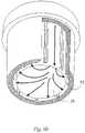
- FIG. 5is a top view of the bowl of the filtration device of the present invention.
- FIG. 6 ais a partial section view of the present invention which shows fluid channels with arrow representation of the fluid flow path.
- FIG. 6 bis an underside view of the device of FIG. 6 a.
- FIG. 7is an underside view of the top cap and housing with arrows representing the fluid flow paths.
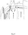
- FIG. 8is a partial sectional view of the present invention which shows a fluid channel and arrow representations of fluid flow paths.
- FIG. 9is a partial sectional view of the present invention which shows a fluid channel and the convergence of fluid flow paths access point to force air bubbles above filter cartridge.
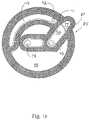
- FIG. 10is a bottom view of an alternative housing cover of this invention.
- FIG. 11is a bottom view of an alternative top cap of this invention used in conjunction with the housing cover of FIG. 10 .
- FIG. 12is a flow diagram illustrating an automated method for operating the device of this invention.
- the flow direction of both bubbles removed from fluid being filtered and the filtered fluid within the filtration device of this inventiondepends upon the mode in which the device is being operated.
- the filtration device of this inventioncan be operated with the vent either open or closed.
- the filtration deviceis filled with fluid and additional fluid is pumped through the device with the vent open to remove the majority of gas and bubbles from the device.
- bubble-laden fluidis also passed through the vent.
- the ventis closed and the fluid being filtered is pumped through the filter device of this invention.
- bubblesare constantly separated from the fluid being filtered and are collected at or near the vent.
- fluidis recirculated through the filtration device for a period of time to assure complete or substantially complete gas removal from the pores of the filter to minimize the amount of fluid that is wasted.
- the ventis opened and bubbles are expelled from the filtration device.
- the ventthen is closed and bubble-free fluid can be dispensed to a point of use.
- the devicewill collect additional bubbles and another vent operation is needed. Again, bubbles and fluid will be expelled through the vent.
- a first channelis positioned in a housing cover of the filtration device and is positioned to be in direct fluid communication with the vent.
- a second channelis positioned in a top cap above the filter membrane of the filtration device and is positioned to be in direct fluid communication with the first channel.
- the first channelaccumulates bubbles from the fluid as the fluid enters the filtration device.
- the first channelalso is positioned to accept bubbles recovered in the second channel.
- the second channelaccumulates any bubbles that either collect or form on the upstream side of the filtration membrane of the filtration device.
- the present inventionprovides a liquid filtration device with internal flow paths that facilitate the removal of air bubbles therefrom, the device comprising a housing, said housing including a bowl; a cap and a cover, the cover having internal and external surfaces and characterized by apertures therein that serve as fluid inlet, outlet and a vent, whereby said cap, cover and bowl are combined in such a manner that fluid channels are created, such channels facilitating sweeping bubbles out of the device and toward the vent, said channels including a fluid channel that directs fluid toward that portion of the housing where the vent is located; a fluid channel that directs fluid to sweep the bottom of the bowl; and a fluid channel that directs fluid to sweep the undersurface of the cap.
- the deviceis designed so that the inlet and vent fluid flow path cross-sectional areas are controlled in a manner such that an optimal fluid velocity is achieved for bubble removal and separation, thereby increasing the efficiency of bubble removal.
- the underside of said top caphas a sloping surface, said sloping surface having a nadir and zenith which is utilized during venting and filtration cycles as well as between cycles.
- a sloping surfacewill facilitate removal of bubble from the device.
- the surface zenithis juxtaposed to the vent aperture so the bubbles are more efficiently removed from the fluid.
- vent pathswill converge at or near the nadir of the volume between the cap and the cover. It is understood that this volume will be where air bubbles to be purged will congregate.
- the surface zenithis juxtaposed to the vent aperture so the bubbles are more efficiently removed.
- the internal surface of the coverwill have a vent ridge, the zenith of said vent ridge positioned substantially near the vent aperture.
- the ventis located directly above a vent aperture while restricting the vent fluid path to maintain fluid velocity to force gas from the fluid.
- the vent processis automatically controlled such that minimal fluid is lost during the vent process.
- the present inventionprovides a method of removing air bubbles from a device intended to filter fluid, said device including an inlet, outlet and vent and said device characterized by being subjected to filtration and vent processes, the method comprising providing fluid channels that are swept during filtration and vent processes. Fluid channels are provided that facilitate the sweeping of air bubbles from the surfaces of the device towards a vent, whereby use of the device in either filtration or venting will remove air bubbles from the device.
- a device of the present inventionincludes an outlet 30 , an inlet 32 and a vent 34 that are formed from the housing cover 36 .
- the housing cover 36is fitted to the top cap 38 and housing bowl 42 .
- Filter media 40is contained within the housing bowl 42 .
- the arrowsindicate how fluid will flow in the device. Diverter 44 alters the fluid flow path from the inlet towards the vent 34 . When the filtration device is filtering fluid, the majority of the fluid will pass directly from the inlet 32 to the housing bowl 42 while depositing air bubbles in the vicinity of the vent 34 .
- the housing cover 36is provided with a first channel 31 which extends about the entire or substantially entire circumference of housing cover 36 and provides a pathway for gas and bubbles to be directed to vent 34 .
- the top cap 38is provided with a second channel 33 which extends substantially the entire circumference of top cap 38 and provides a pathway for gas from inlet fluid to be directed into the first channel 31 and then through vent 34 .
- the housing cover 36has its internal surface 37 angled towards the vent side 35 of the housing cover 36 .
- the first channel 31spirals up from the outlet side 39 of the housing cover 36 to the vent 34 ( FIG. 2 b ) to remove all additional gas bubbles.
- inlet fluidis redirected from the center of the housing to the side of the housing by the diverter 44 where the vent 34 ( FIG. 2 b ) is located for this particular design.
- This configurationforces bubble-laden fluid from the inlet 32 ( FIG. 2 b ) to travel towards the vent 34 ( FIG. 2 b ).
- the fluid velocitycan be regulated such that buoyant forces and residence time are optimized for efficient bubble removal.
- the fluidthen travels down the side fluid channel 46 .
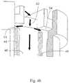
- FIGS. 4 a and 4 billustrate the inlet fluid being directed below the top cap 38 ( FIG. 2 b ) through the cut out 52 where it then is split off. Most of the fluid travels down the side fluid channel 46 created with two ribs 49 found on the inside of the bowl 42 ( FIG. 2 b ) to sweep the housing bowl bottom 25 ( FIG. 6 b ) to prevent stagnant fluid locations and the formation of gel particles. The other portion of the inlet fluid enters fluid channels 53 and 54 to sweep out gas pockets around the underside of the top cap 38 ( FIG. 2 b ). By creating a mechanical seal between the top cap 38 ( FIG. 2 b ) and the housing bowl 42 ( FIG. 2 b ), a flow path which allows fluid to travel beneath the top cap 38 ( FIG. 2 b ) and then back above on the opposite side through cut out 51 is generated with two channels 53 and 54 .
- FIG. 5illustrates the two larger ribs 49 positioned a short distance below the top cap seal ridge 55 to direct the inlet fluid to sweep the bottom of bowl 42 ( FIG. 2 b ) and the underside of the top cap 38 ( FIG. 2 b ).
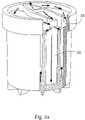
- FIGS. 6 a and 6 billustrate the flow of liquid as shown by the arrows.
- the inlet fluidis directed down the side channel 46 created by ribs 49 ( FIG. 5 ) and sweeps the volume between the bottom of the filter media 40 ( FIG. 2 b ) and the bottom inner surface of bowl 42 .
- the fluidis also directed through channels 53 and 54 ( FIG. 4 b ) to sweep the underside of the top cap 38 .
- FIG. 7illustrates the fluid flow as it is directed about the underside 57 of the top cap 38 ( FIG. 2 b ) through second channel 33 ( FIG. 2 b ) on an increasing slope to eliminate gas bubbles.
- FIG. 8illustrates the converging flow paths to access point 48 directing air bubbles through second channel 33 , through cut out 51 and above the top cap 38 ( FIG. 2 b ) into the volume between the top cap 38 ( FIG. 2 b ) and the cover 36 ( FIG. 2 b ).
- FIG. 9illustrates the flow path being directed back above the top cap 38 at the lowest location (nadir) 58 of the volume under the housing cover 36 ( FIG. 2 b ). This ensures that the liquid is forcing the gas bubbles along the underside of the top cap 38 ( FIG. 2 b ) to channel 31 ( FIG. 2 b ).
- FIG. 10illustrates a housing cover 88 with a restricted fluid flow path 71 is provided to prevent reverse fluid flow along channel 73 .
- the restricted flow path 71allows critical surfaces to be swept during the vent process alone. During the vent process, only a small amount of the fluid entering the fluid inlet 93 is able to pass directly to the vent 92 while the remainder of the fluid velocity is maintained to continue fluid flow below the top cap 81 ( FIG. 11 ) of the filter cartridge 40 ( FIG. 2 b ) and sweep the underside of the top cap 81 . The fluid then converges to the access point 84 of the vent groove 73 where the fluid velocity can be more easily maintained with a small cross-sectional area.
- the housing cover 70is provided with vent 92 , fluid inlet 93 and fluid outlet 75 . Both inner surfaces 90 and 77 slope toward gas vent ridge 87 to facilitate gas flow to gas vent 92 .
- the under surface 94 of top cap 81is provided with gas channel 83 which converges to access point 84 which is in fluid communication with channel 73 ( FIG. 10 ).
- Top cap 81also is provided with outlet 85 which is in fluid communication with outlet 75 ( FIG. 10 ).
- the top cap of FIG. 11is bonded to housing cover 88 to block area 86 thereby to reduce the hold-up volume and create the fluid flow paths of the filtration apparatus.
- the present inventionalso provides a method for operating the liquid filtration device of this invention in systems for filtering and dispensing process fluids.
- filtersare installed dry between a dispense mechanism (e.g. diaphragm pump, air pressurized canister, etc) and an outlet nozzle that directs the fluid onto a substrate such as a semiconductor wafer or optical disc.
- a dispense mechanisme.g. diaphragm pump, air pressurized canister, etc
- the process fluidis pushed into the filter and flushed out both the vent and the outlet ports until each fluid stream contains no visible air bubbles.
- the fluid sent out the vent and outletcontains many bubbles, and it is well known that bubbles can cause defects on or in a coated substrate. Therefore, this bubble-laden fluid is normally directed to waste and not re-used, and this practice can consume a significant amount of fluid.
- Process fluidscan be expensive ($1,000 to $10,0000 per liter) and minimizing waste by more efficiently eliminating bubbles is important.
- Typical filtration devicesare not optimized to remove bubbles.
- the preferred operation orientation to remove bubblesuses the filter with the fluid inlet at the bottom and the vent at the top. Although this efficiently removes large gas bubbles from the device, smaller bubbles introduced through the inlet rise slowly along the outside of the membrane. Purging these bubbles from the upstream side of the device takes considerable time and wastes fluid. In addition, bubbles can be absorbed by the membrane, resulting in de-wet spots causing shorter filter lifetime and bubble induced substrate defects.
- a microprocessorcontrols the actions of two pumps with a filter between them to allow for many process benefits.
- the designs of these systemsalso allow for recirculation of bubble-laden fluid to minimize the amount of fluid that is wasted during start-up of a new filter.
- fluidis pushed through the filter to the downstream side, where the bubble-laden fluid (from gas removed from the pores of the filter membrane) is cycled back to the inlet of the pump. This fluid is then brought back to the upstream side of the filter. Since the membrane pores are now filled with the process fluid, the membrane is a more effective (but not completely effective) barrier to bubble passage.
- Impact LHVD filterthe bubble laden fluid is directed to the bottom of the filter.
- Bubblesmust then rise by buoyant forces to the filter's vent where they are removed either by an automatic means (software triggered vent valve) or by a manual means (manually actuated vent valve). Although this is a more efficient method for removing bubbles from the filter and conserving fluid, waste is still generated, as the venting process is not optimized. For all of these systems, bubble venting is not optimized as the venting process releases not just bubbles but a bubble saturated fluid stream. Since bubbles do not rise quickly in many process fluids, the motion of the fluid toward the vent is required to remove the bubbles (effectively, the bubbles are carried along by the fluid stream). In addition, the smaller the bubbles to be removed, the more fluid that is ejected in the stream.
- Bubble venting with the liquid filtration device of this inventioncan use an algorithm to automatically control the venting of filters (“smart venting”). Specifically, smart venting will limit the number of times that the filter undergoes a vent cycle, and it will limit the amount of fluid that is lost during each vent cycle.
- filtersare vented during start-up and during operations as follows:
- the filterIn a TST system during filter start-up, the filter is vented every fifth cycle to remove entrapped bubbles. Typically, the vent valve opens for 250 milliseconds, and approximately 50 to 150 microliters of fluid is sent to waste. During a typical start-up and preconditioning process, the filter can be vented more than 200 times. Therefore, this process wastes between approximately 10 milliliters and 30 milliliters of fluid. Also, during normal operation, the filter is vented every cycle, again resulting in between 50 and 150 microliters being lost per each dispense.
- ventingis usually a manual process and is at the discretion and convenience of the operator. During start-up, venting is more frequent, but the manual aspect of venting results in between 50 to 100 milliliters of fluid loss. Also, since there is typically no recirculation of the filter's downstream fluid, an additional 500 to 1500 milliliters can be wasted conditioning the filter. Finally, during operation, venting can be done once per day, and again, between 20 and 30 milliliters can be lost each time.
- liquid filtration device of this inventionsmart venting is programmable and automated. On a single stage system, this could be accomplished by using an “intelligent” manifold and the device of this invention.
- the current IMPACT ST manifoldis a passive device, but it can be made to do smart venting by adding a microprocessor and several fluid connections (e.g., solenoid valves, tees). A description of such a system is shown in FIG. 12 .
- the manifold with the filter device of this invention 70controls the operation of solenoid vent valve 72 and solenoid recirculation valve 74 .
- the manifold with the device of this inventionis also in communication with a pump 89 .
- Tee connection 76is positioned so that fluid can be directed either through recirculation valve 74 or through the stop and suckback valve 78 to the substrate 84 .
- Tee 80is positioned both to accept fluid from fluid source 82 during normal operation or from valve 74 when the fluid is recirculated to the manifold and filter device 70 .
- recirculation valve 74 and stop and suckback valve 78are closed and vent valve 72 is opened. Fluid is then sent into the manifold to fill the housing of the filtration device. After the housing is full, fluid can then be recirculated automatically while vent valve 72 is closed and recirculation valve 74 is open so that vent loss can be minimized.
- valve 74At selected times during recirculation (either timed or after a certain number of cycles), the recirculation valve 74 is closed and the vent valve 72 is opened to remove gas from the manifold and filter 70 . After the filter has been primed, valve 74 is closed and valve 78 is opened so that fluid can be deposited on substrate 91 .
- the number of cycles between ventingcould be lengthened by using the device of this invention. Since bubbles are preferentially trapped and coalesce at the top of the filtration device, they are not in contact with or pass by the filter membrane. As such, they will not form de-wet spots (i.e., causing shorter filter lifetime or introducing bubble induced substrate defects). Therefore, the time between vent processes can be increased.
- vent valve openingtime and geometry
- the vent valvemust be sufficiently open to allow for bubble-laden fluid to flow through the valve.
- airwith its lower viscosity
- opening the ventever so slightly for a short time interval would allow air to pass through while not allowing fluid to pass. This could be accomplished by either setting a short vent opening time or controlling the vent valve to minimize its open orifice area. Both would be effective in minimizing the opening of the valve for different viscosity fluids, and both would minimize fluid loss through the vent.
- the automatic operation method of this inventioncan be further improved by incorporation of the following features:
- This degassercan be installed on the filter's vent line. Also, on a single stage system, it can be upstream of the filter; and on a two stage technology system it is positioned on the upstream side of the pump (but downstream of the line used to recirculate the fluid during start-up).
- Such a degasserremove bubbles and prevent microbubble formation without affecting the fluid stream. This also has the advantage of practically eliminating venting during normal operation.
- Other degassing meanse.g., sparging, heating, vacuum, etc.
- those meansusually result in undesirable changes to the process fluid (e.g., viscosity change due to solvent evaporation).
- (B)Install a bubble detector either in the vent line, in the vent port of the filter itself or in the manifold that connects the filtration device to a two stage technology system. Venting then can be enabled only when the bubble detector senses a sufficient quantity of gas with a signal being read by a microprocessor. In addition, venting can be controlled such that only bubbles are vented and not fluid.
Landscapes
- Chemical & Material Sciences (AREA)
- Chemical Kinetics & Catalysis (AREA)
- Engineering & Computer Science (AREA)
- Water Supply & Treatment (AREA)
- Degasification And Air Bubble Elimination (AREA)
- Filtering Of Dispersed Particles In Gases (AREA)
- External Artificial Organs (AREA)
Abstract
Description
This application claims priority to and is a continuation of U.S. application Ser. No. 11/591,283, filed Nov. 1, 2006, issued on Aug. 5, 2008 as U.S. Pat. No. 7,407,594, which is a continuation of U.S. application Ser. No. 11/281,102, filed Nov. 16, 2005, now abandoned, which is a continuation of U.S. application Ser. No. 11/019,966, filed Dec. 21, 2004, issued on Jan. 3, 2006 as U.S. Pat. No. 6,982,041, which is a divisional of U.S. application Ser. No. 10/380,314, filed Mar. 12, 2003, issued on Jan. 25, 2005, as U.S. Pat. No. 6,846,409, which is the U.S. National Stage of International Application No. PCT/US01/028771, filed Sep. 13, 2001, published in English, which claims the benefit of U.S. Application No. 60/232,209, filed on Sep. 13, 2000. The entire teachings of the above applications are incorporated herein by reference.
The IMPACT® LVHD filter, sold by Mykrolis Corporation of Bedford, Mass., has a low hold up volume which is very advantageous due to the high cost of the process fluids principally filtered by the device: photoresist, dielectrics, anti-reflectives and optical disc materials. The IMPACT LHVD filter provides superior filtration to prevent debris in the process fluid from being deposited onto the substrate and from causing defects.
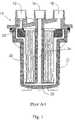
A sectional view of the current IMPACT filter may be found inFIG. 1 .FIG. 1 provides a device that uses three independent connections, avent 12, afeed 14, and anoutlet 16, that can interface with either a stand alone manifold or directly to a dispense system such as the RGEN™ or IntelliGen® dispense systems that are manufactured by Mykrolis Corporation. The process fluid enters through theinlet port 14 and flows through theinlet tube 24 to thehousing bottom 25. The process fluid then flows through thevertical membrane filter 26 to theoutlet port 16, where the purified fluid is directed back to the manifold or dispense system. Thevent port 12 allows bubbles that accumulate on the upstream side of the filter to exit thehousing 22. To better eliminate bubbles from the filter, the top surface of thehousing cap 18 is set at an angle directed up to thevent port 12. This allows air bubbles to gradually rise to the highest point in thehousing 20 and to exit thehousing 22.
A more detailed description of the attributes and benefits of the IMPACT LHVD filter may be found in Mykrolis Applications Note No. MA068 entitled “New Photochemical Filtration Technology for Process Improvement” by M. Clarke and Kwok-Shun Cheng. This paper was originally presented at the INTERFACE '97 Poster Session on Nov. 10, 1997. Also, benefits of the IMPACT LHVD are presented in Mykrolis Applications Note No. MAL109 entitled “Improving Photolithography Equipment OEE with the IMPACT ST Manifold” by M. Clarke.
Although the design and performance of the IMPACT LHVD filter is much improved over other filtration devices, it is also not fully optimized for bubble venting. In the IMPACT LHVD filter, bubble-laden fluid is forced to the bottom of the device to sweep the bottom with fluid to prevent fluid stagnation at the bottom and the formation of gel particles. Therefore, any entrained bubbles must then rise to the vent. Again, the slowly rising bubbles from the bottom will require more time and chemical to purge them from the device.
To compensate for the shortcomings of filters and how they are used in standard filtration and dispense systems, Mykrolis developed integrated filtration and dispense systems called “Two Stage Technology” or “TST”. The designs of these TST systems allow for recirculation of bubble-laden fluid to minimize the amount of fluid that is wasted during start-up of a new filter. Although these systems more efficiently remove bubbles from the filter and conserve fluid, waste is still generated, as the venting process is not optimized.
A more detailed description of the operation of a Two Stage Technology System is given in Mykrolis Applications Note No. MAL111 entitled “Understanding the Operating Cycles of Millipore Two-Stage Technology Photochemical Dispense Systems” by M. Clarke.
For all of these systems (even including TST systems), bubble venting is still not optimized as the venting process release not just bubbles but a bubble saturated fluid stream. Since bubbles do not rise quickly in many process fluids, the motion of the fluid toward the vent is required to remove the bubbles (effectively, the bubbles are carried along by the fluid stream). In addition, the smaller the bubbles to be removed, the more fluid that is ejected in the stream.
It is apparent from the aforementioned applications notes and discussions that gas bubbles are a concern to semiconductor manufacturers. However, the current IMPACT filter or any other currently available product, inadequately addresses the need to sweep bubbles from all surfaces of the filtration device as well as to initiate bubble removal prior to filtration.
Accordingly, it would be desirable to provide a liquid filtration device wherein bubble removal from the liquid being filtered be initiated prior to filtration so that the gas bubbles removed are positioned near the vent, thereby facilitating gas bubble removal from the liquid being filtered. Also, it would be desirable to have the system to provide a means for automatic venting of a liquid filtration device that minimizes the amount of fluid loss.
The present invention provides a device that eliminates gas bubbles from a fluid by using the fluid's velocity within the device, coupled with specific flow channels, to remove pockets of gas from liquid filtration devices. The properly designed flow paths direct fluid into locations where gas bubbles will most likely collect.
The present invention provides a device and method for eliminating gas bubbles from a liquid within a housing having a housing cover that will allow for faster and more efficient removal of entrained bubbles. The new device and method uses a portion of the fluid's velocity at the device inlet to sweep around the underside of a flange of a filter cartridge within the device. This will force gas bubbles within the fluid to rise above the filter membrane and adjacent the inside surface of the housing cover. The liquid streams positioned beneath the filter cartridge's flange then converge to the inside surface of the housing cover and proceed to force gas bubbles from the fluid to proceed toward the vent port of the device.
In addition, the present invention provides a method for effecting automatic venting of bubbles from the fluid being filtered.
It is an object of the present invention to provide a liquid filtration device that eliminates gas bubbles from fluid within the device during a vent cycle.
It is also an object of the present invention to provide a liquid filtration device that removes gas bubbles from a fluid by utilizing surfaces in the device while the device is operated in a filtration cycle.
The flow direction of both bubbles removed from fluid being filtered and the filtered fluid within the filtration device of this invention depends upon the mode in which the device is being operated. The filtration device of this invention can be operated with the vent either open or closed. In an initial operating mode of the filtration device, the filtration device is filled with fluid and additional fluid is pumped through the device with the vent open to remove the majority of gas and bubbles from the device. During this mode of operation, bubble-laden fluid is also passed through the vent. Subsequent to this initial mode of operation, the vent is closed and the fluid being filtered is pumped through the filter device of this invention. During this mode, bubbles are constantly separated from the fluid being filtered and are collected at or near the vent. In a preferred mode of operation, fluid is recirculated through the filtration device for a period of time to assure complete or substantially complete gas removal from the pores of the filter to minimize the amount of fluid that is wasted. At specific intervals, the vent is opened and bubbles are expelled from the filtration device. The vent then is closed and bubble-free fluid can be dispensed to a point of use. After some period of time, the device will collect additional bubbles and another vent operation is needed. Again, bubbles and fluid will be expelled through the vent.
The bubbles entrained within the fluid are forced from the fluid along one of two locations within the filtration device. A first channel is positioned in a housing cover of the filtration device and is positioned to be in direct fluid communication with the vent. A second channel is positioned in a top cap above the filter membrane of the filtration device and is positioned to be in direct fluid communication with the first channel. The first channel accumulates bubbles from the fluid as the fluid enters the filtration device. The first channel also is positioned to accept bubbles recovered in the second channel. The second channel accumulates any bubbles that either collect or form on the upstream side of the filtration membrane of the filtration device. Thus, the filtration device recovers bubbles which are immediately released from the fluid upon entering the filtration device and which are released from the fluid prior to filtration.
The present invention provides a liquid filtration device with internal flow paths that facilitate the removal of air bubbles therefrom, the device comprising a housing, said housing including a bowl; a cap and a cover, the cover having internal and external surfaces and characterized by apertures therein that serve as fluid inlet, outlet and a vent, whereby said cap, cover and bowl are combined in such a manner that fluid channels are created, such channels facilitating sweeping bubbles out of the device and toward the vent, said channels including a fluid channel that directs fluid toward that portion of the housing where the vent is located; a fluid channel that directs fluid to sweep the bottom of the bowl; and a fluid channel that directs fluid to sweep the undersurface of the cap.
In a preferred embodiment, the device is designed so that the inlet and vent fluid flow path cross-sectional areas are controlled in a manner such that an optimal fluid velocity is achieved for bubble removal and separation, thereby increasing the efficiency of bubble removal.
In a preferred embodiment, the underside of said top cap has a sloping surface, said sloping surface having a nadir and zenith which is utilized during venting and filtration cycles as well as between cycles. Such a sloping surface will facilitate removal of bubble from the device. Preferably, the surface zenith is juxtaposed to the vent aperture so the bubbles are more efficiently removed from the fluid.
In a preferred embodiment, vent paths will converge at or near the nadir of the volume between the cap and the cover. It is understood that this volume will be where air bubbles to be purged will congregate. Preferably for this embodiment, the surface zenith is juxtaposed to the vent aperture so the bubbles are more efficiently removed.
In a preferred embodiment of the present invention, the internal surface of the cover will have a vent ridge, the zenith of said vent ridge positioned substantially near the vent aperture.
In another preferred embodiment, the vent is located directly above a vent aperture while restricting the vent fluid path to maintain fluid velocity to force gas from the fluid.
In another preferred embodiment, the vent process is automatically controlled such that minimal fluid is lost during the vent process.
The present invention provides a method of removing air bubbles from a device intended to filter fluid, said device including an inlet, outlet and vent and said device characterized by being subjected to filtration and vent processes, the method comprising providing fluid channels that are swept during filtration and vent processes. Fluid channels are provided that facilitate the sweeping of air bubbles from the surfaces of the device towards a vent, whereby use of the device in either filtration or venting will remove air bubbles from the device.
Referring toFIGS. 2 aand2b, a device of the present invention includes anoutlet 30, aninlet 32 and avent 34 that are formed from thehousing cover 36. Thehousing cover 36 is fitted to thetop cap 38 andhousing bowl 42.Filter media 40 is contained within thehousing bowl 42. The arrows indicate how fluid will flow in the device.Diverter 44 alters the fluid flow path from the inlet towards thevent 34. When the filtration device is filtering fluid, the majority of the fluid will pass directly from theinlet 32 to thehousing bowl 42 while depositing air bubbles in the vicinity of thevent 34. Thehousing cover 36 is provided with afirst channel 31 which extends about the entire or substantially entire circumference ofhousing cover 36 and provides a pathway for gas and bubbles to be directed to vent34. Thetop cap 38 is provided with asecond channel 33 which extends substantially the entire circumference oftop cap 38 and provides a pathway for gas from inlet fluid to be directed into thefirst channel 31 and then throughvent 34.
Referring toFIGS. 3 aand3b, thehousing cover 36 has itsinternal surface 37 angled towards thevent side 35 of thehousing cover 36. Thefirst channel 31 spirals up from theoutlet side 39 of thehousing cover 36 to the vent34 (FIG. 2 b) to remove all additional gas bubbles.
Also, as shown inFIGS. 3 aand3b, inlet fluid is redirected from the center of the housing to the side of the housing by thediverter 44 where the vent34 (FIG. 2 b) is located for this particular design. This configuration forces bubble-laden fluid from the inlet32 (FIG. 2 b) to travel towards the vent34 (FIG. 2 b). By controlling the cross-sectional area, the fluid velocity can be regulated such that buoyant forces and residence time are optimized for efficient bubble removal. The fluid then travels down theside fluid channel 46.
The present invention also provides a method for operating the liquid filtration device of this invention in systems for filtering and dispensing process fluids. In a typical application (also called single stage technology), filters are installed dry between a dispense mechanism (e.g. diaphragm pump, air pressurized canister, etc) and an outlet nozzle that directs the fluid onto a substrate such as a semiconductor wafer or optical disc. To remove air from the filter's pores, the process fluid is pushed into the filter and flushed out both the vent and the outlet ports until each fluid stream contains no visible air bubbles. Unfortunately, the fluid sent out the vent and outlet contains many bubbles, and it is well known that bubbles can cause defects on or in a coated substrate. Therefore, this bubble-laden fluid is normally directed to waste and not re-used, and this practice can consume a significant amount of fluid. Process fluids can be expensive ($1,000 to $10,0000 per liter) and minimizing waste by more efficiently eliminating bubbles is important.
Typical filtration devices are not optimized to remove bubbles. The preferred operation orientation to remove bubbles uses the filter with the fluid inlet at the bottom and the vent at the top. Although this efficiently removes large gas bubbles from the device, smaller bubbles introduced through the inlet rise slowly along the outside of the membrane. Purging these bubbles from the upstream side of the device takes considerable time and wastes fluid. In addition, bubbles can be absorbed by the membrane, resulting in de-wet spots causing shorter filter lifetime and bubble induced substrate defects.
With a TST system, a microprocessor controls the actions of two pumps with a filter between them to allow for many process benefits. The designs of these systems also allow for recirculation of bubble-laden fluid to minimize the amount of fluid that is wasted during start-up of a new filter. During start-up of a dry filter, fluid is pushed through the filter to the downstream side, where the bubble-laden fluid (from gas removed from the pores of the filter membrane) is cycled back to the inlet of the pump. This fluid is then brought back to the upstream side of the filter. Since the membrane pores are now filled with the process fluid, the membrane is a more effective (but not completely effective) barrier to bubble passage. In the prior art Impact LHVD filter, the bubble laden fluid is directed to the bottom of the filter. Bubbles must then rise by buoyant forces to the filter's vent where they are removed either by an automatic means (software triggered vent valve) or by a manual means (manually actuated vent valve). Although this is a more efficient method for removing bubbles from the filter and conserving fluid, waste is still generated, as the venting process is not optimized. For all of these systems, bubble venting is not optimized as the venting process releases not just bubbles but a bubble saturated fluid stream. Since bubbles do not rise quickly in many process fluids, the motion of the fluid toward the vent is required to remove the bubbles (effectively, the bubbles are carried along by the fluid stream). In addition, the smaller the bubbles to be removed, the more fluid that is ejected in the stream.
Bubble venting with the liquid filtration device of this invention can use an algorithm to automatically control the venting of filters (“smart venting”). Specifically, smart venting will limit the number of times that the filter undergoes a vent cycle, and it will limit the amount of fluid that is lost during each vent cycle.
Typically, filters are vented during start-up and during operations as follows:
(A) In a TST system during filter start-up, the filter is vented every fifth cycle to remove entrapped bubbles. Typically, the vent valve opens for 250 milliseconds, and approximately 50 to 150 microliters of fluid is sent to waste. During a typical start-up and preconditioning process, the filter can be vented more than 200 times. Therefore, this process wastes between approximately 10 milliliters and 30 milliliters of fluid. Also, during normal operation, the filter is vented every cycle, again resulting in between 50 and 150 microliters being lost per each dispense.
(B) In non-TST applications, venting is usually a manual process and is at the discretion and convenience of the operator. During start-up, venting is more frequent, but the manual aspect of venting results in between 50 to 100 milliliters of fluid loss. Also, since there is typically no recirculation of the filter's downstream fluid, an additional 500 to 1500 milliliters can be wasted conditioning the filter. Finally, during operation, venting can be done once per day, and again, between 20 and 30 milliliters can be lost each time.
With the liquid filtration device of this invention, smart venting is programmable and automated. On a single stage system, this could be accomplished by using an “intelligent” manifold and the device of this invention. The current IMPACT ST manifold is a passive device, but it can be made to do smart venting by adding a microprocessor and several fluid connections (e.g., solenoid valves, tees). A description of such a system is shown inFIG. 12 . In this figure, the manifold with the filter device of thisinvention 70 controls the operation ofsolenoid vent valve 72 andsolenoid recirculation valve 74. The manifold with the device of this invention is also in communication with apump 89.Tee connection 76 is positioned so that fluid can be directed either throughrecirculation valve 74 or through the stop andsuckback valve 78 to thesubstrate 84.Tee 80 is positioned both to accept fluid fromfluid source 82 during normal operation or fromvalve 74 when the fluid is recirculated to the manifold andfilter device 70. At start-up of a new filter,recirculation valve 74 and stop andsuckback valve 78 are closed and ventvalve 72 is opened. Fluid is then sent into the manifold to fill the housing of the filtration device. After the housing is full, fluid can then be recirculated automatically whilevent valve 72 is closed andrecirculation valve 74 is open so that vent loss can be minimized. At selected times during recirculation (either timed or after a certain number of cycles), therecirculation valve 74 is closed and thevent valve 72 is opened to remove gas from the manifold andfilter 70. After the filter has been primed,valve 74 is closed andvalve 78 is opened so that fluid can be deposited onsubstrate 91.
In most cases, the number of cycles between venting could be lengthened by using the device of this invention. Since bubbles are preferentially trapped and coalesce at the top of the filtration device, they are not in contact with or pass by the filter membrane. As such, they will not form de-wet spots (i.e., causing shorter filter lifetime or introducing bubble induced substrate defects). Therefore, the time between vent processes can be increased.
Also, the vent valve opening (time and geometry) can be minimized. Currently, the vent valve must be sufficiently open to allow for bubble-laden fluid to flow through the valve. However, since the bubbles will coalesce into larger bubbles, air (with its lower viscosity) flows more easily than fluid through a small passage, and opening the vent ever so slightly for a short time interval would allow air to pass through while not allowing fluid to pass. This could be accomplished by either setting a short vent opening time or controlling the vent valve to minimize its open orifice area. Both would be effective in minimizing the opening of the valve for different viscosity fluids, and both would minimize fluid loss through the vent.
The automatic operation method of this invention can be further improved by incorporation of the following features:
(A) Install a membrane contactor type of degasser in the system. This degasser can be installed on the filter's vent line. Also, on a single stage system, it can be upstream of the filter; and on a two stage technology system it is positioned on the upstream side of the pump (but downstream of the line used to recirculate the fluid during start-up). Such a degasser remove bubbles and prevent microbubble formation without affecting the fluid stream. This also has the advantage of practically eliminating venting during normal operation. Other degassing means (e.g., sparging, heating, vacuum, etc.) can be used, but those means usually result in undesirable changes to the process fluid (e.g., viscosity change due to solvent evaporation).
(B) Install a bubble detector either in the vent line, in the vent port of the filter itself or in the manifold that connects the filtration device to a two stage technology system. Venting then can be enabled only when the bubble detector senses a sufficient quantity of gas with a signal being read by a microprocessor. In addition, venting can be controlled such that only bubbles are vented and not fluid.
While this invention has been particularly shown and described with references to preferred embodiments thereof, it will be understood by those skilled in the art that various changes in form and details may be made therein without departing from the scope of the invention encompassed by the appended claims.
Claims (33)
1. A liquid filtration device with internal flow paths that facilitate the purging of air bubbles therefrom, the device comprising:
a housing, the housing including a bowl, a cap, and a cover, the bowl defining an opening that receives a filter medium, the cap substantially covering the opening of the bowl and the filter medium, the cover being fitted to the cap and the bowl, the cover including a fluid inlet, a fluid outlet, and a vent; and
a first fluid channel directing fluid from the inlet toward the vent, the first fluid channel defined in a first volume between the cover and the cap, the first fluid channel accumulating bubbles from the fluid near the vent as the fluid enters the filter device, the inlet and vent being positioned at the same end of the housing.
2. The device ofclaim 1 further comprising:
a second fluid channel directing fluid from the first fluid channel to sweep an undersurface of the cap, the second fluid channel being defined in a second volume between an undersurface of the cap and the filter medium, the second fluid channel accumulating bubbles from the fluid that collect or form near the undersurface of the cap; and
an aperture directing the fluid from the second channel back to the first fluid channel, the aperture being defined in the cap and coupling the second fluid channel with the first fluid channel, the first fluid channel accumulating bubbles recovered in the second fluid channel near the vent.
3. The device ofclaim 2 further comprising:
a third fluid channel directing the fluid from the first fluid channel toward the bottom of the bowl, the third fluid channel being defined between the bowl and the filter medium, the third fluid channel enabling the fluid to sweep the bottom of the bowl; and
a plurality of fourth fluid channels further directing the fluid from the bottom of the bowl toward the second fluid channel.
4. The device ofclaim 3 wherein the third fluid channel is defined between at least two ribs positioned axially along the inside of the housing bowl.
5. The device ofclaim 3 wherein the plurality of fourth fluid channels converge with the second fluid channel at or near the nadir of the volume between the cap and the cover of the housing.
6. The device ofclaim 5 wherein the plurality of fourth fluid channels are each defined between at least two ribs positioned axially along the inside of the housing bowl.
7. The device ofclaim 2 wherein the second fluid channel extends substantially about the circumference of the cap, the second fluid channel defining a flow path allowing fluid to travel beneath the cap and then back above the cap through an aperture into the first fluid channel for expulsion through the vent.
8. The device ofclaim 1 wherein the first fluid channel is characterized by cross-sectional areas that facilitate a fluid velocity that enables removal of bubbles from the fluid flowing through the first fluid channel.
9. The device ofclaim 1 wherein the first fluid channel extends substantially about the circumference of the housing cover, such that the first fluid channel spirals up from an outlet side of the cover to provide a pathway for bubbles to be directed to the vent.
10. The device ofclaim 1 wherein the underside of the cap includes a sloped surface, the sloped surface having a nadir and a zenith, the zenith being juxtaposed to the vent.
11. The device ofclaim 1 wherein the housing cover includes an internal surface angled toward a vent side of the cover to provide a pathway for bubbles to be directed to the vent.
12. The device ofclaim 1 wherein the vent is capable of opening and closing for time intervals that minimize fluid loss.
13. The device ofclaim 1 further comprising:
a degassing membrane contactor coupled externally to the filter device to further eliminate bubbles.
14. A liquid filtration device with internal flow paths that facilitate the purging of air bubbles therefrom, the device comprising:
a housing, the housing comprising a bowl, a cap, and a cover, the bowl defining an opening that receives a filter medium, the cap substantially covering the opening of the bowl and the filter medium, the cover being fitted to the cap and the bowl, the cover including a fluid inlet, a fluid outlet, and a vent;
a first fluid channel directing fluid from the inlet toward the vent, the first fluid channel defined in a first volume between the cover and the cap, the first fluid channel accumulating bubbles from the fluid near the vent as the fluid enters the filter device;
a second fluid channel directing the fluid from the first fluid channel to sweep an undersurface of the cap, the second fluid channel being defined in a second volume between an undersurface of the cap and the filter medium, the second fluid channel accumulating bubbles from the fluid that collect or form near the undersurface of the cap; and
an aperture directing the fluid from the second fluid channel back to the first fluid channel, the aperture defined in the cap and coupling the second fluid channel with the first fluid channel, the first fluid channel accumulating bubbles recovered in the second fluid channel near the vent.
15. A liquid filtration device with internal flow paths that facilitate the purging of air bubbles therefrom, the device comprising:
a housing, the housing comprising a bowl, a cap, and a cover, the bowl defining an opening that receives a filter medium, the cap substantially covering the opening of the bowl and the filter medium, the cover being fitted to the cap and the bowl, the cover including a fluid inlet, a fluid outlet, and a vent;
a first fluid channel directing the fluid from the inlet of the filter device toward the bottom of the bowl, the first fluid channel defined between the bowl and the filter medium, the first fluid channel enabling the fluid to sweep the bottom of the bowl; and
at least one second fluid channel directing the fluid from the bottom of the bowl toward the vent for removal of bubbles in the fluid.
16. The device ofclaim 15 wherein the housing cover includes an interior surface being angled toward the vent to enable bubbles removed from the fluid to rise to the vent.
17. The device ofclaim 15 wherein an interior wall of the housing bowl is fitted to the exterior wall of the filter medium, such that the first fluid channel is defined therebetween for directing the fluid from the inlet of the filter device toward the bottom of the bowl.
18. The device ofclaim 15 wherein at least one flow channel is defined between the interior bottom of the housing bowl and the exterior bottom of the filter medium, such that at least one fluid channel is defined therebetween for sweeping the interior bottom of the housing bowl.
19. A liquid filtration device with internal flow paths that facilitate the purging of air bubbles therefrom, the device comprising:
a housing, the housing comprising a bowl, a cap, and a cover, the bowl defining an opening that receives a filter medium, the cap substantially covering the opening of the bowl and the filter medium, the cover being fitted to the cap and the bowl, the cover including a fluid inlet, a fluid outlet, and a vent, a first fluid channel being defined in a first volume between the cover and the cap, the inlet and vent being positioned at the same end of the housing;
a second fluid channel directing the fluid from the first fluid channel to sweep an undersurface of the cap, the second fluid channel being defined in a second volume between an undersurface of the cap and the filter medium, the second fluid channel accumulating bubbles from the fluid that collect or form near the undersurface of the cap; and
an aperture directing the fluid from the second fluid channel back to the first fluid channel, the aperture defined in the cap and coupling the second fluid channel with the first fluid channel, the first fluid channel accumulating bubbles recovered in the second fluid channel near the vent.
20. The device ofclaim 19 , wherein the vent is capable of opening to enable the bubbles that accumulate near the vent to be expelled.
21. The device ofclaim 19 wherein the second fluid channel extends substantially about the circumference of the cap, the second fluid channel defining a flow path allowing fluid to travel beneath the cap and then back above the cap through an aperture into the first fluid channel for expulsion through the vent.
22. The device ofclaim 19 further comprising:
a third fluid channel directing the fluid from the first fluid channel toward the bottom of the bowl, the third fluid channel defined between the bowl and the filter medium and enabling the fluid to sweep the bottom of the bowl; and
a plurality of fourth fluid channels directing the fluid from the bottom of the bowl toward the second fluid channel.
23. The device ofclaim 22 wherein the third fluid channel is defined between at least two ribs positioned axially along the inside of the housing bowl.
24. The device ofclaim 22 wherein the plurality of fourth fluid channels converge with the second fluid channel at or near the nadir of the volume between the cap and the cover of the housing.
25. The device ofclaim 24 wherein the plurality of fourth fluid channels are each defined between at least two ribs positioned axially along the inside of the housing bowl.
26. The device ofclaim 22 wherein an interior wall of the housing bowl is fitted to the exterior wall of the filter medium, such that the third fluid channel is defined therebetween for directing the fluid from the inlet of the filter device toward the bottom of the bowl.
27. The device ofclaim 19 wherein the first fluid channel is characterized by cross-sectional areas that facilitate a fluid velocity that enables removal of bubbles from the fluid flowing through the first fluid channel.
28. The device ofclaim 19 wherein the first fluid channel extends substantially about the circumference of the housing cover, such that the first fluid channel spirals up from an outlet side of the cover to provide a pathway for bubbles to be directed to the vent.
29. The device ofclaim 19 wherein the underside of the cap includes a sloped surface, the sloped surface having a nadir and a zenith, the zenith being juxtaposed to the vent.
30. The device ofclaim 19 wherein the housing cover includes an internal surface angled toward a vent side of the cover to provide a pathway for bubbles to be directed to the vent.
31. The device ofclaim 19 wherein the vent is capable of opening and closing for time intervals that minimize fluid loss.
32. The device ofclaim 19 further comprising:
a degassing membrane contactor externally coupled in fluid connection with the filter device to further eliminate bubbles.
33. The device ofclaim 19 wherein at least one flow channel is defined between the interior bottom of the housing bowl and the exterior bottom of the filter medium, such that at least one fluid channel is defined therebetween for sweeping the interior bottom of the housing bowl.
Priority Applications (1)
| Application Number | Priority Date | Filing Date | Title |
|---|---|---|---|
| US12/221,309US7572367B2 (en) | 2000-09-13 | 2008-08-01 | Liquid filtration device |
Applications Claiming Priority (7)
| Application Number | Priority Date | Filing Date | Title |
|---|---|---|---|
| US23220900P | 2000-09-13 | 2000-09-13 | |
| US10/380,314US6846409B2 (en) | 2000-09-13 | 2001-09-13 | Liquid filtration device |
| PCT/US2001/028771WO2002022232A1 (en) | 2000-09-13 | 2001-09-13 | Liquid filtration device |
| US11/019,966US6982041B2 (en) | 2000-09-13 | 2004-12-21 | Liquid filtration device |
| US11/281,102US20060070961A1 (en) | 2000-09-13 | 2005-11-16 | Liquid filtration device |
| US11/591,283US7407594B2 (en) | 2000-09-13 | 2006-11-01 | Liquid filtration device |
| US12/221,309US7572367B2 (en) | 2000-09-13 | 2008-08-01 | Liquid filtration device |
Related Parent Applications (1)
| Application Number | Title | Priority Date | Filing Date |
|---|---|---|---|
| US11/591,283ContinuationUS7407594B2 (en) | 2000-09-13 | 2006-11-01 | Liquid filtration device |
Publications (2)
| Publication Number | Publication Date |
|---|---|
| US20080302712A1 US20080302712A1 (en) | 2008-12-11 |
| US7572367B2true US7572367B2 (en) | 2009-08-11 |
Family
ID=22872266
Family Applications (5)
| Application Number | Title | Priority Date | Filing Date |
|---|---|---|---|
| US10/380,314Expired - Fee RelatedUS6846409B2 (en) | 2000-09-13 | 2001-09-13 | Liquid filtration device |
| US11/019,966Expired - Fee RelatedUS6982041B2 (en) | 2000-09-13 | 2004-12-21 | Liquid filtration device |
| US11/281,102AbandonedUS20060070961A1 (en) | 2000-09-13 | 2005-11-16 | Liquid filtration device |
| US11/591,283Expired - Fee RelatedUS7407594B2 (en) | 2000-09-13 | 2006-11-01 | Liquid filtration device |
| US12/221,309Expired - Fee RelatedUS7572367B2 (en) | 2000-09-13 | 2008-08-01 | Liquid filtration device |
Family Applications Before (4)
| Application Number | Title | Priority Date | Filing Date |
|---|---|---|---|
| US10/380,314Expired - Fee RelatedUS6846409B2 (en) | 2000-09-13 | 2001-09-13 | Liquid filtration device |
| US11/019,966Expired - Fee RelatedUS6982041B2 (en) | 2000-09-13 | 2004-12-21 | Liquid filtration device |
| US11/281,102AbandonedUS20060070961A1 (en) | 2000-09-13 | 2005-11-16 | Liquid filtration device |
| US11/591,283Expired - Fee RelatedUS7407594B2 (en) | 2000-09-13 | 2006-11-01 | Liquid filtration device |
Country Status (8)
| Country | Link |
|---|---|
| US (5) | US6846409B2 (en) |
| EP (1) | EP1322395B1 (en) |
| JP (1) | JP2004508183A (en) |
| KR (1) | KR100582967B1 (en) |
| CN (1) | CN1183993C (en) |
| DE (1) | DE60144097D1 (en) |
| TW (1) | TW508260B (en) |
| WO (1) | WO2002022232A1 (en) |
Cited By (2)
| Publication number | Priority date | Publication date | Assignee | Title |
|---|---|---|---|---|
| US7815805B2 (en) | 1996-07-12 | 2010-10-19 | Entegris, Inc. | Connector apparatus and system including connector apparatus |
| US9731231B2 (en) | 2013-03-07 | 2017-08-15 | Taiwan Semiconductor Manufacturing Company, Ltd. | Laminar flow intake channeling device |
Families Citing this family (50)
| Publication number | Priority date | Publication date | Assignee | Title |
|---|---|---|---|---|
| DE60116873T2 (en) | 2000-05-12 | 2006-07-20 | Pall Corp. | FILTER |
| KR100850340B1 (en) | 2000-05-12 | 2008-08-04 | 폴 코포레이션 | Filtration systems and fitting arrangements for filtration systems |
| KR100582967B1 (en) | 2000-09-13 | 2006-05-24 | 엔테그리스, 아이엔씨. | Liquid filtration equipment |
| US20030019819A1 (en)* | 2001-07-30 | 2003-01-30 | Karl Fritze | Hot disconnect replaceable water filter assembly |
| EP1448928B1 (en) | 2001-09-13 | 2005-12-28 | Mykrolis Corporation | Separation module |
| US7469932B2 (en) | 2001-09-13 | 2008-12-30 | Entegris, Inc. | Receptor for a separation module |
| TWI245163B (en)* | 2003-08-29 | 2005-12-11 | Asml Netherlands Bv | Lithographic apparatus and device manufacturing method |
| TW200610573A (en)* | 2004-06-03 | 2006-04-01 | Mykrolis Corp | Fluid treating apparatus |
| US7393388B2 (en)* | 2005-05-13 | 2008-07-01 | United Technologies Corporation | Spiral wound fuel stabilization unit for fuel de-oxygenation |
| US7435283B2 (en)* | 2005-05-18 | 2008-10-14 | United Technologies Corporation | Modular fuel stabilization system |
| US7465336B2 (en)* | 2005-06-09 | 2008-12-16 | United Technologies Corporation | Fuel deoxygenation system with non-planar plate members |
| US7377112B2 (en) | 2005-06-22 | 2008-05-27 | United Technologies Corporation | Fuel deoxygenation for improved combustion performance |
| CN102389666B (en)* | 2005-07-22 | 2014-10-29 | 曼·胡默尔有限公司 | Filter element for fuel filter |
| US20070101731A1 (en)* | 2005-09-07 | 2007-05-10 | United Technologies Corporation | Deoxygenated fuel-cooled environmental control system pre-cooler for an aircraft |
| US9258259B2 (en)* | 2005-09-30 | 2016-02-09 | Nokia Technologies Oy | Retrieval of offline instant messages |
| US7615104B2 (en) | 2005-11-03 | 2009-11-10 | United Technologies Corporation | Fuel deoxygenation system with multi-layer oxygen permeable membrane |
| US20070130956A1 (en)* | 2005-12-08 | 2007-06-14 | Chen Alexander G | Rich catalytic clean burn for liquid fuel with fuel stabilization unit |
| US7582137B2 (en)* | 2006-01-18 | 2009-09-01 | United Technologies Corporation | Fuel deoxygenator with non-planar fuel channel and oxygen permeable membrane |
| US7824470B2 (en)* | 2006-01-18 | 2010-11-02 | United Technologies Corporation | Method for enhancing mass transport in fuel deoxygenation systems |
| US7569099B2 (en)* | 2006-01-18 | 2009-08-04 | United Technologies Corporation | Fuel deoxygenation system with non-metallic fuel plate assembly |
| JP5354525B2 (en)* | 2006-08-25 | 2013-11-27 | インテグリス・インコーポレーテッド | Air ventable filter device |
| PE20091163A1 (en) | 2007-11-01 | 2009-08-09 | Wyeth Corp | ANTIBODIES FOR GDF8 |
| JPWO2009069402A1 (en)* | 2007-11-29 | 2011-04-07 | インテグリス・インコーポレーテッド | Filter unit and filter cartridge |
| KR100921743B1 (en)* | 2007-12-14 | 2009-10-15 | 한국생산기술연구원 | Filtration device for vacuum pump |
| CN102596355A (en)* | 2009-11-12 | 2012-07-18 | 唐纳森公司 | Liquid filter construction for freezing environments |
| US20120223002A1 (en)* | 2011-02-24 | 2012-09-06 | Lin Zhenwu | Modular filter capsule apparatus |
| US9682335B2 (en) | 2011-02-24 | 2017-06-20 | Saint-Gobain Performance Plastics Corporation | Modular filter capsule apparatus |
| JP6195436B2 (en)* | 2012-10-29 | 2017-09-13 | スリーエム イノベイティブ プロパティズ カンパニー | FILTER DEVICE, FILTER DEVICE ASSEMBLY METHOD, FILTER METHOD USING FILTER DEVICE, FILTER PRODUCTION METHOD USING FILTER DEVICE |
| US9421498B2 (en)* | 2012-11-12 | 2016-08-23 | Pall Corporation | Systems and methods for conditioning a filter assembly |
| US9656197B2 (en)* | 2012-11-12 | 2017-05-23 | Pall Corporation | Systems and methods for conditioning a filter assembly |
| US9719504B2 (en)* | 2013-03-15 | 2017-08-01 | Integrated Designs, L.P. | Pump having an automated gas removal and fluid recovery system and method |
| JP2015106656A (en)* | 2013-11-29 | 2015-06-08 | 東京エレクトロン株式会社 | Filter device |
| US11351509B2 (en)* | 2013-12-06 | 2022-06-07 | Taiwan Semiconductor Manufacturing Company, Ltd. | Filter with seal treatment |
| JP2014195807A (en)* | 2014-06-18 | 2014-10-16 | 株式会社ロキテクノ | Filter module attaching/detaching device and filtration unit |
| US11840797B1 (en) | 2014-11-26 | 2023-12-12 | Microban Products Company | Textile formulation and product with odor control |
| CN112870823B (en)* | 2014-12-16 | 2023-05-30 | 圣戈班生物高新材料(杭州)有限公司 | Modular filter capsule device |
| US10121685B2 (en)* | 2015-03-31 | 2018-11-06 | Tokyo Electron Limited | Treatment solution supply method, non-transitory computer-readable storage medium, and treatment solution supply apparatus |
| US10729991B2 (en) | 2015-06-22 | 2020-08-04 | 3M Innovative Properties Company | Compact cross-flow contactor |
| GB201516863D0 (en)* | 2015-09-23 | 2015-11-04 | Castrol Ltd | Fluid method and system |
| CN105781828A (en)* | 2015-11-24 | 2016-07-20 | 黄梅福德银汽配有限公司 | Novel automatic exhaust diesel oil filter seat |
| CN108473936A (en) | 2015-12-22 | 2018-08-31 | 康宁股份有限公司 | Cell separation apparatus and its application method |
| EP3436174B1 (en)* | 2016-07-11 | 2021-07-07 | Hewlett-Packard Development Company, L.P. | Froth coalescing |
| US11213775B2 (en) | 2017-09-25 | 2022-01-04 | Cummins Filtration Ip, Inc. | Fuel filter cartridges with automated air-bleeding internal features |
| US11517838B2 (en) | 2018-07-30 | 2022-12-06 | Shaw Development LLC | Aqueous fluid filter assembly with aeration mitigation |
| CN110052060B (en)* | 2019-04-24 | 2022-07-01 | 杭州科百特过滤器材有限公司 | Hollow fiber degassing membrane module |
| EP3990155A1 (en) | 2019-06-25 | 2022-05-04 | Donaldson Company, Inc. | Filter element endcap with shroud |
| US11241644B2 (en) | 2020-04-13 | 2022-02-08 | Pall Corporation | Adapter for filter device and method of use |
| JP7724612B2 (en)* | 2021-01-14 | 2025-08-18 | 株式会社ロキテクノ | Vented filter vessel system |
| CN113413672B (en)* | 2021-06-28 | 2023-02-28 | 张春燕 | Filter |
| JP2024538338A (en)* | 2021-11-04 | 2024-10-18 | インテグリス・インコーポレーテッド | Filter Cartridge Assembly |
Citations (245)
| Publication number | Priority date | Publication date | Assignee | Title |
|---|---|---|---|---|
| US136631A (en) | 1873-03-11 | Improvement in steam-power-brake couplings | ||
| US420209A (en) | 1890-01-28 | Pipe-coupling for railway-cars | ||
| US468390A (en) | 1892-02-09 | Low-water alarm | ||
| US872174A (en) | 1907-03-25 | 1907-11-26 | Ralph M Fyock | Automatic train-pipe coupling. |
| US872707A (en) | 1907-06-29 | 1907-12-03 | Peter Beahm | Automatic connector for train-pipes. |
| US891718A (en) | 1907-06-21 | 1908-06-23 | Thomas B Mcmillan | Coupling. |
| US898214A (en) | 1903-11-27 | 1908-09-08 | Edward E Gold | Automatic pipe-coupling for railway-cars. |
| US940334A (en) | 1909-01-11 | 1909-11-16 | William D Leftwich | Coupling mechanism. |
| US967516A (en) | 1909-09-01 | 1910-08-16 | Henry Cain J | Automatic air-coupling. |
| US1070110A (en) | 1912-04-27 | 1913-08-12 | James A Tate | Automatic air-brake coupling or connector. |
| US1186068A (en) | 1915-10-30 | 1916-06-06 | Warren C Benjamin | Air-brake coupling. |
| US1221682A (en) | 1916-04-20 | 1917-04-03 | William C Coffield | Air-coupling. |
| US1389012A (en) | 1920-07-10 | 1921-08-30 | John W Roberts | Pipe-coupling for railway rolling-stock |
| US1786066A (en) | 1928-09-12 | 1930-12-23 | Cobb Connector Company | Train-pipe coupler |
| GB344502A (en) | 1929-12-05 | 1931-03-05 | Metallgesellschaft Ag | Improvements in filters |
| US1886398A (en) | 1931-08-13 | 1932-11-08 | Arthur C Harrell | Automatic train pipe coupling |
| US2462488A (en) | 1945-06-07 | 1949-02-22 | Fram Corp | Control plate for filter cartridges |
| US2997180A (en) | 1957-06-03 | 1961-08-22 | Chrysler Corp | Anti-vapor-lock fuel filter |
| US3052863A (en) | 1961-03-16 | 1962-09-04 | Ibm | Contact connector operating devices |
| US3107601A (en) | 1958-09-02 | 1963-10-22 | Richard L Longmire | Filtration and recirculation system for deep fat cooking apparatus |
| US3214195A (en) | 1962-05-25 | 1965-10-26 | Crawford Fitting Co | Coupling device for interconnecting multiple fluid lines |
| US3399776A (en) | 1965-09-02 | 1968-09-03 | Robert R. Knuth | Detachable snap-on filter for a hydraulic system |
| US3469863A (en) | 1967-04-05 | 1969-09-30 | Trico Products Corp | Fluid coupling assembly |
| US3485516A (en) | 1966-09-16 | 1969-12-23 | Vickers Zimmer Ag | Double-pipe line flange connection |
| US3493115A (en) | 1968-01-29 | 1970-02-03 | Ultra Tech Corp | Cam lock cartridge system |
| US3519133A (en) | 1968-07-09 | 1970-07-07 | Dover Corp | Fluid filter means |
| US3560377A (en) | 1969-01-21 | 1971-02-02 | Amicon Corp | Apparatus and process for filtering fluids |
| US3628662A (en) | 1970-03-26 | 1971-12-21 | Marvel Eng Co | Filter antidrain valve assembly |
| US3695446A (en) | 1970-10-15 | 1972-10-03 | Culligan Int Co | Membrane module assembly |
| US3706184A (en) | 1969-06-09 | 1972-12-19 | Matter Mfg Corp | Wall-recessed suction cleaner |
| US3727764A (en) | 1971-11-22 | 1973-04-17 | H Ogden | Filtering apparatus having an integrally removable filter cartridge |
| US3734851A (en) | 1969-12-29 | 1973-05-22 | K Matsumura | Method and device for purifying blood |
| US3802564A (en) | 1972-06-09 | 1974-04-09 | W Turman | Oil filter and adapter |
| US3812659A (en) | 1972-08-02 | 1974-05-28 | Whirlpool Co | Canister vacuum cleaner latching means |
| US3880757A (en) | 1971-09-08 | 1975-04-29 | Gary Thomason | Filtering system |
| US3935106A (en) | 1974-01-23 | 1976-01-27 | Lipner Herbert D | Water filter assembly |
| US3947080A (en) | 1971-06-14 | 1976-03-30 | Underwriters Safety Device Co. | Quick-connect-disconnect terminal block assembly |
| US3950251A (en) | 1974-03-25 | 1976-04-13 | Rayne International | Filter with quick-connect coupling |
| US4013384A (en) | 1974-07-18 | 1977-03-22 | Iwaki Co., Ltd. | Magnetically driven centrifugal pump and means providing cooling fluid flow |
| US4047847A (en) | 1975-03-26 | 1977-09-13 | Iwaki Co., Ltd. | Magnetically driven centrifugal pump |
| US4089549A (en) | 1976-10-21 | 1978-05-16 | Stratoflex, Inc. | Simultaneous plural fluid conductor connections |
| US4151823A (en) | 1977-07-28 | 1979-05-01 | Grosse Leland J | Quick-change oil filter/reservoir system for internal combustion engine |
| US4174231A (en) | 1977-09-08 | 1979-11-13 | Hobgood Harold G | Method for flushing the crankcase of an internal combustion engine |
| US4187179A (en) | 1978-08-14 | 1980-02-05 | Harms John F | Electrically grounded filter plate |
| US4269219A (en) | 1978-04-17 | 1981-05-26 | Helge Dybvig | Fittings for releasably interconnecting a fuel tank with an internal combustion engine |
| US4283284A (en) | 1979-07-18 | 1981-08-11 | Baxter Travenol Laboratories, Inc. | Hollow fiber dialyzer end seal system |
| JPS56122893U (en) | 1980-02-20 | 1981-09-18 | ||
| US4298358A (en) | 1979-01-11 | 1981-11-03 | Baxter Travenol Laboratories, Inc. | Gas separating and venting filter |
| JPS5727588A (en) | 1980-07-22 | 1982-02-13 | Hitachi Chemical Co Ltd | Brush |
| US4321911A (en) | 1979-08-15 | 1982-03-30 | Offutt Worthington W | Modular solar collector system |
| DE3100564A1 (en) | 1981-01-10 | 1982-08-12 | August Beul, Armaturenfabrik und Metallgießerei, 5952 Attendorn | Assembly connection piece for supply-pipe filter stations |
| US4344777A (en) | 1980-01-07 | 1982-08-17 | Siposs George G | Directed flow bubble trap for arterial blood |
| US4404103A (en) | 1981-11-05 | 1983-09-13 | Drath Edwin H | Rocking swivel hose connectors and method |
| US4411783A (en) | 1981-12-23 | 1983-10-25 | Shiley Incorporated | Arterial blood filter with improved gas venting |
| US4414109A (en) | 1980-09-29 | 1983-11-08 | Purex Corporation | Multi-ported valve with sealing network between valve body and rotor |
| US4416775A (en) | 1981-12-14 | 1983-11-22 | Std Filter Company, Inc. | In-line filter and cartridge therefor |
| GB2137110A (en) | 1983-03-29 | 1984-10-03 | Swinney Eng | Filter Element Mounting |
| US4494775A (en) | 1982-09-30 | 1985-01-22 | William Nash Company, Inc. | Fluid coupling |
| US4498989A (en) | 1981-02-23 | 1985-02-12 | Nippondenso Co., Ltd. | Fluid filter element and support |
| US4500426A (en) | 1979-02-15 | 1985-02-19 | Daicel Chemical Industries, Ltd. | Semipermeable membrane elements |
| US4522717A (en) | 1983-06-24 | 1985-06-11 | Brust John E | Filter apparatus |
| US4524807A (en) | 1982-05-21 | 1985-06-25 | Humphrey Products Company | Snap-together modular manifold construction |
| US4529512A (en) | 1981-01-19 | 1985-07-16 | Clark Equipment Company | Hydraulic reservoir |
| US4535997A (en) | 1983-06-24 | 1985-08-20 | Brust John E | Sealing system |
| US4555130A (en) | 1983-04-01 | 1985-11-26 | The United States Of America As Represented By The Secretary Of The Navy | Diver's umbilical quick-disconnect device |
| US4559136A (en) | 1984-08-31 | 1985-12-17 | Vortex Innerspace Products, Inc. | Aquarium filtering system |
| US4568456A (en) | 1983-05-26 | 1986-02-04 | Wafilin B.V. | Sealing for an installation for purifying liquids by membrane filtration |
| US4591438A (en) | 1984-02-27 | 1986-05-27 | Hitachi, Ltd. | Water purifier |
| JPS61119686A (en) | 1984-11-14 | 1986-06-06 | Teru Ramu Kk | Parallel flat plate type plasma etching device |
| US4610781A (en) | 1983-12-30 | 1986-09-09 | Baxter Travenol Laboratories, Inc. | Fluid processing system with flow control manifold |
| US4629568A (en) | 1983-09-26 | 1986-12-16 | Kinetico, Inc. | Fluid treatment system |
| US4629563A (en) | 1980-03-14 | 1986-12-16 | Brunswick Corporation | Asymmetric membranes |
| US4636307A (en) | 1983-09-16 | 1987-01-13 | Mitsubishi Rayon Co., Ltd. | Hollow-fiber filtering module and water purification device utilizing it |
| US4645601A (en) | 1984-08-31 | 1987-02-24 | Everpure, Inc. | Quick change reverse osmosis assembly |
| US4654142A (en) | 1985-11-18 | 1987-03-31 | Everpure, Inc. | Filtering system |
| US4664420A (en) | 1986-09-02 | 1987-05-12 | Island Rubber & Equipment Co., Inc. | Pneumatic self-sealing female coupling incorporating combination locking tumblers |
| EP0231862A2 (en) | 1986-01-27 | 1987-08-12 | Cuno Incorporated | Quick-change filter cartridge and head therefor |
| US4698154A (en) | 1983-07-29 | 1987-10-06 | Mohn Juergen | Apparatus for filtering and separating flowing media |
| US4719012A (en) | 1986-05-30 | 1988-01-12 | Caterpillar Inc. | Twist on disposable filter |
| JPS6311168Y2 (en) | 1981-03-23 | 1988-04-01 | ||
| US4735716A (en) | 1986-01-27 | 1988-04-05 | Cuno Corporated | Quick-change filter cartridge and head therefor |
| EP0269054A2 (en) | 1986-11-27 | 1988-06-01 | Bayerische Motoren Werke Aktiengesellschaft, Patentabteilung AJ-3 | Filter arrangement for the purification of fluids, in particular lubricating oils of combustion engines |
| GB2198430A (en) | 1986-12-03 | 1988-06-15 | British Nuclear Fuels Plc | Liquid treatment apparatus |
| USRE32711E (en)* | 1981-12-23 | 1988-07-12 | Shiley, Inc. | Arterial blood filter with improved gas venting |
| US4759571A (en) | 1986-10-31 | 1988-07-26 | D. W. Zimmerman Mfg., Inc. | Fluid transfer module with multiple flow paths |
| US4806240A (en) | 1987-06-12 | 1989-02-21 | Cuno, Incorporated | Adapter and cartridge assembly |
| US4820174A (en) | 1986-08-06 | 1989-04-11 | Amp Incorporated | Modular connector assembly and filtered insert therefor |
| US4824564A (en) | 1986-11-04 | 1989-04-25 | Eastman Kodak Company | Dry sump liquid filter |
| US4846800A (en) | 1987-10-14 | 1989-07-11 | Kenneth Ouriel | Two chambered autotransfuser device and method of use |
| US4857191A (en) | 1987-11-28 | 1989-08-15 | Joachim Wolf | Filter device |
| US4857189A (en) | 1988-10-13 | 1989-08-15 | Everpure, Inc. | Filter cartridge with a lugged concentric closure portion |
| US4861476A (en) | 1985-05-28 | 1989-08-29 | Amafilter Membrantechnik Gmbh | Separator cell for pressure filtering and reverse osmosis |
| US4870961A (en) | 1986-09-22 | 1989-10-03 | Barnard Gordon D | Medical ventilator tube and manifold assembly |
| US4879032A (en) | 1984-06-04 | 1989-11-07 | Allied Resin Corporation | Fluid separatory devices having improved potting and adhesive compositions |
| DE3820675A1 (en) | 1988-06-18 | 1989-12-21 | Porsche Ag | OIL FILTER FOR AN INTERNAL COMBUSTION ENGINE |
| FR2633368A1 (en) | 1988-06-23 | 1989-12-29 | Peugeot | Device for connecting flexible hoses onto any member by means of a mounting plate or the like |
| US4900449A (en) | 1987-05-20 | 1990-02-13 | Gelman Sciences | Filtration membranes and method of making the same |
| US4900065A (en) | 1988-10-31 | 1990-02-13 | Dlh Industries, Inc. | Quick-connect fluid coupling |
| US4904382A (en) | 1987-11-23 | 1990-02-27 | Everpure, Inc. | Filter cartridge security for locking between operating and non-operating positions |
| US4932987A (en) | 1989-05-25 | 1990-06-12 | Jorge Molina | Extra corporeal air eliminator |
| US4944776A (en) | 1989-10-05 | 1990-07-31 | Andrew Corporation | Dehumidifier for waveguide system |
| EP0390715A1 (en) | 1989-03-29 | 1990-10-03 | Societe D'etudes Et D'innovation Dans Le Materiel Agricole (Seima) | Multiple fluidic connection |
| US4964984A (en) | 1989-06-14 | 1990-10-23 | Electromedics, Inc. | Blood filter |
| US4966699A (en) | 1988-05-25 | 1990-10-30 | Terumo Kabushiki Kaisha | Hollow fiber membrane fluid processor |
| EP0408375A2 (en) | 1989-07-12 | 1991-01-16 | Pall Corporation | Filter assemblies and couplings |
| JPH03115092A (en) | 1989-09-29 | 1991-05-16 | Fuji Seiki Co Ltd | Fixed restoring force spring unit with damper |
| US5022986A (en) | 1990-01-11 | 1991-06-11 | John Lang | Manifold and disposable filter assembly |
| US5041220A (en) | 1990-01-09 | 1991-08-20 | Minntech Corporation | Hollow fiber filter cartridge for a standarized housing |
| US5057131A (en) | 1988-09-26 | 1991-10-15 | The Scott Fetzer Company | Vacuum cleaner filter bag assembly |
| US5066391A (en) | 1990-08-22 | 1991-11-19 | Faria Manuel S | Reusable liquid filter assembly |
| US5069780A (en) | 1990-06-04 | 1991-12-03 | Infinitex | Ultrafiltration device and process |
| US5076925A (en) | 1989-04-28 | 1991-12-31 | X-Flow B.V. | Process for preparing a microporous membrane and such a membrane |
| US5085772A (en) | 1989-09-15 | 1992-02-04 | Eskofot A/S | Filter for filtration of fluids |
| US5096230A (en) | 1991-03-20 | 1992-03-17 | General Resource Corporation | Quick release adapter for connecting an exhaust removal hose to a vehicle tail pipe using magnets |
| US5108598A (en) | 1990-02-14 | 1992-04-28 | Ultra Flow, Inc. | Horizontal motion quick-disconnect filter system with recirculating bypass |
| US5125691A (en) | 1989-11-06 | 1992-06-30 | Lazarevic Bogdan | High pressure gas pipeline having concentric tubes and vent tubes |
| EP0492627A2 (en) | 1990-12-27 | 1992-07-01 | Kanebo Ltd. | Filter container with double construction |
| US5133858A (en) | 1989-11-30 | 1992-07-28 | Layton Manufacturing Corporation | Reverse osmosis water purification apparatus |
| US5139669A (en) | 1990-02-09 | 1992-08-18 | Hospal Industrie | Apparatus with hollow fibres |
| US5139668A (en) | 1989-12-27 | 1992-08-18 | Alberta Research Corporation | Hollow fiber bundle element |
| US5143575A (en) | 1988-11-04 | 1992-09-01 | Robert Bosch Gmbh | Spiral wound filter and method of making same |
| USRE34050E (en) | 1986-03-07 | 1992-09-01 | Everpure, Inc. | Filtering system |
| US5160615A (en) | 1990-04-18 | 1992-11-03 | Terumo Kabushiki Kaisha | Hollow fiber type liquid processing apparatus |
| US5160042A (en) | 1991-11-05 | 1992-11-03 | Praxair Technology, Inc. | Double ended hollow fiber bundle and fluids separation apparatus |
| US5167814A (en) | 1989-06-15 | 1992-12-01 | Cuno, Incorporated | Filter apparatus snap lock cartridge retainer |
| US5167837A (en) | 1989-03-28 | 1992-12-01 | Fas-Technologies, Inc. | Filtering and dispensing system with independently activated pumps in series |
| US5172998A (en) | 1990-12-15 | 1992-12-22 | Yazaki Corporation | Connector with a lever |
| US5178758A (en) | 1992-06-30 | 1993-01-12 | Hwang Ching F | Biochemical water filter |
| US5180490A (en) | 1992-01-31 | 1993-01-19 | Baldwin Filters, Inc. | Lubricant filter assembly with internal bypass lock-out |
| US5192499A (en) | 1989-07-14 | 1993-03-09 | Terumo Kabushiki Kaisha | Fluid processing apparatus and artificial lung |
| EP0535546A1 (en) | 1991-10-03 | 1993-04-07 | Millipore Corporation | Manifold segment stack with intermediate feed manifold |
| JPH05154200A (en) | 1991-12-02 | 1993-06-22 | Sanyo Denshi Kogyo Kk | Oxygen enriched gas supplying device for medical treatment |
| US5221473A (en) | 1989-10-13 | 1993-06-22 | Burrows Bruce D | Filter cartridge assembly for a reverse osmosis purification system |
| JPH05154201A (en) | 1991-12-02 | 1993-06-22 | Sanyo Denshi Kogyo Kk | Oxygen enriched gas feeding device for medical treatment |
| US5230812A (en) | 1992-07-29 | 1993-07-27 | Williams Richard T | Pressure vessel |
| US5230760A (en) | 1991-11-06 | 1993-07-27 | Nippon Roki Co., Ltd. | Method for manufacturing micro membrane pleats type filter cartridge |
| WO1993016315A1 (en) | 1992-02-11 | 1993-08-19 | Huron Products Inc. | Connector for fluid filter |
| US5262069A (en) | 1991-02-16 | 1993-11-16 | Fsk, Inc. | Filter cake scraping method and rotary drum filter using the same |
| US5262068A (en) | 1991-05-17 | 1993-11-16 | Millipore Corporation | Integrated system for filtering and dispensing fluid having fill, dispense and bubble purge strokes |
| JPH06106164A (en) | 1992-09-25 | 1994-04-19 | Matsushita Electric Works Ltd | Water purifier |
| JPH06147383A (en) | 1992-11-07 | 1994-05-27 | Nabco Ltd | Fitting/removing device for pipes |
| US5316347A (en) | 1991-07-09 | 1994-05-31 | Massimo Arosio | Quick-fitting coupling for simultaneously connecting or disconnecting a plurality of couplings |
| US5320752A (en) | 1992-11-03 | 1994-06-14 | Clack Corporation | Water purification system employing modular flat filter assembly |
| US5324483A (en) | 1992-10-08 | 1994-06-28 | Warner-Lambert Company | Apparatus for multiple simultaneous synthesis |
| US5341832A (en) | 1989-05-01 | 1994-08-30 | Foust Harry D | Device and method for the combustion of waste oil |
| US5342518A (en) | 1990-02-14 | 1994-08-30 | Iraco Filtration Systems, Inc. | Filtration system and mount for beverage dispensers and automatic beverage brewing machines |
| US5344194A (en) | 1991-06-03 | 1994-09-06 | Yazaki Corporation | Connectors with lever |
| EP0616826A1 (en) | 1993-02-16 | 1994-09-28 | Amway Corporation | Water filter Cartridges |
| US5354464A (en) | 1990-03-14 | 1994-10-11 | Water Factory Systems | Multi-port connecting device |
| JPH0639008Y2 (en) | 1986-06-04 | 1994-10-12 | 株式会社川口技研 | Square lock rattling prevention device for door locks |
| US5373595A (en) | 1993-03-12 | 1994-12-20 | Irvin Industries Canada Ltd. | Air support device |
| US5380437A (en) | 1993-02-02 | 1995-01-10 | Biomedical Research And Development Laboratories, Inc. | Multifunctional filtration apparatus |
| JPH0717434A (en) | 1993-06-30 | 1995-01-20 | Suzuki Motor Corp | Body side construction |
| US5383690A (en) | 1992-08-25 | 1995-01-24 | Mercedes-Benz Ag | Arrangement for fastening a fluid line to a body particularly a fuel filter for an internal combustion engine |
| US5387339A (en) | 1993-12-17 | 1995-02-07 | Coors Brewing Company | High efficiency liquid filtration system and method for using the same |
| US5389260A (en) | 1993-04-02 | 1995-02-14 | Clack Corporation | Brine seal for tubular filter |
| US5397462A (en) | 1993-08-24 | 1995-03-14 | Matsushita Electric Industrial Co., Ltd. | Filter with laterally removable element and valve means |
| US5397468A (en) | 1992-09-24 | 1995-03-14 | Barnstead Thermolyne | Water purifier cartridge coupling |
| US5401401A (en) | 1993-01-13 | 1995-03-28 | Aquaria Inc. | Hang on tank canister filter |
| US5413711A (en) | 1992-06-18 | 1995-05-09 | Stanadyne Automotive Corp. | Fuel filter with internal vent |
| US5417459A (en) | 1994-02-24 | 1995-05-23 | Sonsub, Inc. | Subsea umbilical connector |
| US5435915A (en) | 1992-04-10 | 1995-07-25 | Pall Corporation | Connector for sealing stacked filter elements |
| US5437483A (en) | 1992-08-26 | 1995-08-01 | Usui Kokusai Sangyo Kaisha Ltd. | Flexible hose joint |
| US5449454A (en) | 1993-01-13 | 1995-09-12 | Aquaria, Inc. | Gas expelling device for a canister type filter |
| US5453184A (en) | 1993-03-23 | 1995-09-26 | Thomas Handtmann | Filter carrier |
| US5462675A (en) | 1994-07-15 | 1995-10-31 | Pall Corporation | Filter assembly and method of reducing hold-up in a filter assembly |
| US5468390A (en) | 1992-11-23 | 1995-11-21 | Rensselaer Polytechnic Institute | Low fouling ultrafiltration and microfiltration aryl polysulfone |
| US5468388A (en) | 1993-07-01 | 1995-11-21 | Sartorius Ag | Filter module with degassing feature |
| US5474683A (en) | 1993-03-03 | 1995-12-12 | Deka Products Limited Partnership | Peritoneal dialysis systems and methods employing pneumatic pressure and temperature-corrected liquid volume measurements |
| US5478119A (en) | 1993-09-16 | 1995-12-26 | The Kendall Company | Polarized manifold connection device |
| US5486288A (en) | 1993-01-26 | 1996-01-23 | Elkay Manufacturing Company | Mounting head with safety shut-off valve for replaceable filter cartridge |
| US5505842A (en) | 1993-11-25 | 1996-04-09 | Atec Automatisierungstechnik Gmbh | Filtering apparatus having individual filtrate drains and rod-shaped filters |
| US5507530A (en) | 1995-05-08 | 1996-04-16 | Soo Tractor Sweeprake Company | Plural male and female fluid coupler connecting mechanism and method |
| US5525225A (en) | 1993-12-13 | 1996-06-11 | Stanadyne Automotive Corp. | Fuel filter with internal vent |
| US5558371A (en) | 1994-09-26 | 1996-09-24 | Respironics, Inc. | Resuscitator |
| DE29618092U1 (en) | 1996-10-18 | 1996-12-12 | Sartorius AG, 37075 Göttingen | Integrity testable filter cassette made of hydrophilic, porous polymer membranes with improved filtration security and filtration performance |
| US5601710A (en) | 1994-07-08 | 1997-02-11 | Samsung Electronics Co., Ltd. | Filtering apparatus of water purifier |
| US5605624A (en) | 1992-01-22 | 1997-02-25 | Alliedsignal Inc | Quick connect/disconnect liquid filter |
| US5632894A (en) | 1994-06-24 | 1997-05-27 | Gish Biomedical, Inc. | Arterial blood filter with upwardly inclining delivery inlet conduit |
| US5651887A (en) | 1990-02-14 | 1997-07-29 | Iraco Filtration Systems, Inc. | Filtration system and mount for beverage dispensers and automatic beverage brewing machines |
| US5653871A (en) | 1996-04-24 | 1997-08-05 | Everpure, Inc. | Filter assembly with O-ring protection |
| FR2745043A1 (en) | 1996-02-16 | 1997-08-22 | Alo Maskiner Ab | Ganged hydraulic connector for loader bucket |
| US5667566A (en) | 1991-09-06 | 1997-09-16 | Reading Technologies, Inc. | Apparatus for water vapor removal from a compressed gas |
| US5667679A (en) | 1996-06-24 | 1997-09-16 | Graver Chemical Company | Filter having a filter element quick-disconnect mount |
| DE19618166A1 (en) | 1994-11-08 | 1997-11-13 | Mann & Hummel Filter | Filter, especially liquid filter |
| US5702597A (en) | 1994-07-26 | 1997-12-30 | Hospal Industrie | Device for preparing a treatment liquid by filtration |
| GB2314516A (en) | 1996-06-26 | 1998-01-07 | Richard Dobson | Integral oil reservoir, filter and tamper-proof valve unit |
| JPH105746A (en) | 1996-06-20 | 1998-01-13 | Osaka Sanai:Kk | Water purifying device and its selector cock |
| EP0818228A1 (en) | 1996-07-12 | 1998-01-14 | Millipore Corporation | Disposable separation module with quick connect capability |
| US5725623A (en) | 1995-09-13 | 1998-03-10 | Electrolux Corporation | Filter and accessory mount for upright vacuum cleaner exhaust port |
| US5744047A (en) | 1990-07-27 | 1998-04-28 | Pall Corporation | Leucocyte depleting filter device and method of use |
| US5762789A (en) | 1996-06-28 | 1998-06-09 | Millipore Corporation | Disposable membrane module with low-dead volume |
| US5762787A (en) | 1995-01-13 | 1998-06-09 | Ziba Design, Inc. | Fluid filtration system having a readily detachable cartridge filter |
| US5779903A (en) | 1995-11-02 | 1998-07-14 | Pall Corporation | Filter assemblies and end caps for filter assemblies |
| US5782791A (en) | 1995-04-27 | 1998-07-21 | Avecor Cardiovascular, Inc. | Method of manufacturing a fluid filter |
| US5816621A (en) | 1997-07-03 | 1998-10-06 | Frost; Terry J. | Quick release mechanism for hydraulic and gas carrying lines |
| US5824217A (en) | 1996-03-27 | 1998-10-20 | Millipore Corporation | Membrane filtration apparatus |
| US5842724A (en) | 1996-12-23 | 1998-12-01 | T. C. Johnson Company | Air brake hose coupling member having an extended locking lug |
| US5842888A (en) | 1994-10-31 | 1998-12-01 | Berg Technology, Inc. | Low cost filtered and shielded electronic connector |
| EP0887100A1 (en) | 1997-06-26 | 1998-12-30 | Fresenius Medical Care Deutschland GmbH | Filtration device and support device for the same |
| US5858224A (en) | 1997-03-18 | 1999-01-12 | Nelson Industries, Inc. | Filter with pressure sensor mounted in housing end |
| US5902551A (en) | 1995-01-13 | 1999-05-11 | Semi-Gas Systems, Inc. | Process gas docking station with point-of-use filter for receiving removable purifier cartridges |
| US5911879A (en) | 1997-09-24 | 1999-06-15 | Eaton Corporation | Refrigerant filter/drier |
| US5922196A (en) | 1995-10-27 | 1999-07-13 | Ing. Walter Hengst Gmbh & Co. Kg | Liquid filter with connection flange |
| US5925025A (en) | 1996-06-05 | 1999-07-20 | Tyco Group S.A.R.L. | Filtration valve cap with reflux clearing feature and related method of use thereof |
| US5927759A (en) | 1998-06-30 | 1999-07-27 | Hyslop; William J. | Connection assembly for an exhaust extraction system |
| US5944990A (en) | 1992-11-30 | 1999-08-31 | Edens; Jeffrey I. | Fluid filter apparatus |
| US5951862A (en) | 1997-02-12 | 1999-09-14 | Lucas Industries Plc | Filter |
| US5984371A (en) | 1995-11-08 | 1999-11-16 | Souete D'etude Et D'innovation Dans Le Materiel Agricole | Hydraulic coupling device |
| US6024229A (en) | 1998-02-27 | 2000-02-15 | Ayers; William R. | Reusable filter assembly |
| JP2000077588A (en) | 1998-05-05 | 2000-03-14 | Internatl Rectifier Corp | High current capacity semiconductor device package and lead frame with large area connection post and modified outline |
| US6048454A (en) | 1997-03-18 | 2000-04-11 | Jenkins; Dan | Oil filter pack and assembly |
| USD423081S (en) | 1998-07-10 | 2000-04-18 | Millipore Corporation | Connector |
| US6059797A (en) | 1998-06-17 | 2000-05-09 | Ensurg, Inc. | Self-disposing ligating band dispenser |
| US6059318A (en) | 1996-04-30 | 2000-05-09 | E. I. Du Pont De Nemours And Company | Lateral entry remotely operated coupling system |
| US6139738A (en) | 1999-03-10 | 2000-10-31 | Parker-Hannifin Corporation | Cartridge filter with integrated threading having anti-rotation feature |
| US6142063A (en) | 1999-01-19 | 2000-11-07 | Keurig, Inc. | Automated beverage brewing system |
| US6142170A (en) | 1998-03-25 | 2000-11-07 | Belfer; William A. | Apparatus and method for dispensing disinfectant compositions for disinfecting water systems and lines |
| EP1057493A2 (en) | 1999-06-02 | 2000-12-06 | B. Braun Melsungen Ag | Cartridge holder for a dialysis apparatus |
| US6159366A (en) | 1997-08-21 | 2000-12-12 | Carroll; Randall Scott | No spill, self-bleeding filter |
| US6176904B1 (en)* | 1999-07-02 | 2001-01-23 | Brij M. Gupta | Blood filter |
| US6251270B1 (en) | 1999-01-14 | 2001-06-26 | Societe Nationale d'Etude et de Consrtuction de Moteurs d'Aviation “SNECMA” | Fuel circuit with protected main filter |
| WO2001064312A1 (en) | 2000-03-01 | 2001-09-07 | Mykrolis Corporation | Disposable fluid separation device and manifold assembly design with easy change-out feature |
| US6290523B1 (en) | 1997-08-14 | 2001-09-18 | Daimlerchrysler Corporation | Self docking instrument panel connector system |
| WO2001095993A2 (en) | 2000-05-12 | 2001-12-20 | Pall Corporation | Filtration systems and fitting arrangements for filtration systems |
| WO2002022232A1 (en) | 2000-09-13 | 2002-03-21 | Mykrolis Corporation | Liquid filtration device |
| US6378907B1 (en) | 1996-07-12 | 2002-04-30 | Mykrolis Corporation | Connector apparatus and system including connector apparatus |
| US6387271B1 (en) | 1995-09-14 | 2002-05-14 | Pall Corporation | Method for separating solid particulates from a liquid |
| US20020060189A1 (en) | 2000-11-22 | 2002-05-23 | Wayne Conrad | Method and apparatus for controlling a household water purifier |
| US20020163187A1 (en) | 2001-02-13 | 2002-11-07 | Pelfrey Rick D. | Pneumatic coupling |
| US6523861B1 (en) | 1998-05-26 | 2003-02-25 | Gary Clancy | Fluid coupling and method of use |
| US6533933B1 (en) | 1998-10-09 | 2003-03-18 | Mykrolis Corporation | Filtration module including unitary filter cartridge-bowl construction |
| WO2003022388A2 (en) | 2001-09-13 | 2003-03-20 | Mykrolis Corporation | Separation module |
| US6547284B2 (en) | 1999-04-08 | 2003-04-15 | Med-Eng Systems Inc. | Automatic or manual quick release latch |
| US6581974B1 (en) | 2001-09-29 | 2003-06-24 | Ragner Manufacturing, Llc | Pivot adaptor attachment for vacuum cleaners |
| US6634509B2 (en) | 2000-03-31 | 2003-10-21 | Kurabo Industries Ltd. | Filtration apparatus |
| US20030213736A1 (en) | 2000-05-12 | 2003-11-20 | Hajime Hiranaga | Filters |
| US6733250B2 (en) | 2001-03-15 | 2004-05-11 | Koganei Corporation | Filter unit, chemical liquid supply system, and chemical liquid supply method |
| US6752159B1 (en) | 2001-08-21 | 2004-06-22 | Motorvac Technologies, Inc. | Dynamic oil flusher cleaning system |
| US6840548B2 (en) | 2002-02-04 | 2005-01-11 | Staubli Faverges | Quick connection for the removable join of pipes |
| US6902671B2 (en) | 2000-12-01 | 2005-06-07 | Millipore Corporation | Chemical process system with multi-functional barrier filter |
| US7029238B1 (en) | 1998-11-23 | 2006-04-18 | Mykrolis Corporation | Pump controller for precision pumping apparatus |
| US7163037B2 (en) | 2005-01-21 | 2007-01-16 | Eaton Corporation | Guiding movement of capless filler neck closure |
| US20070102924A1 (en) | 2001-09-13 | 2007-05-10 | Niermeyer J K | Separation module |
| JP4094705B2 (en) | 1997-07-18 | 2008-06-04 | ヤンマー農機株式会社 | Combine |
Family Cites Families (8)
| Publication number | Priority date | Publication date | Assignee | Title |
|---|---|---|---|---|
| US423081A (en)* | 1890-03-11 | Cable-railway crossing | ||
| DE423081C (en)* | 1923-05-02 | 1925-12-18 | Hoechst Ag | Process for the preparation of sulfoalkyl and sulfoaryl ethers from resinous condensation products derived from phenols |
| US3650251A (en)* | 1970-05-11 | 1972-03-21 | Mack Trucks | Hydraulic valve lifter |
| US4629475A (en)* | 1980-05-13 | 1986-12-16 | Polaroid Corporation | Liquid debubbling apparatus and method |
| US4708157A (en)* | 1986-10-07 | 1987-11-24 | Flowtron Industries, Inc. | Air eliminator for fluid handling systems |
| JPH1043293A (en)* | 1996-08-08 | 1998-02-17 | Senko Ika Kogyo Kk | Device for removing bubble in liquid |
| US5902511A (en)* | 1997-08-07 | 1999-05-11 | North American Refractories Co. | Refractory composition for the prevention of alumina clogging |
| JP2000140524A (en)* | 1998-11-05 | 2000-05-23 | Nippon Rokaki Kk | Filter apparatus |
- 2001
- 2001-09-13KRKR1020037003617Apatent/KR100582967B1/ennot_activeExpired - Fee Related
- 2001-09-13DEDE60144097Tpatent/DE60144097D1/ennot_activeExpired - Lifetime
- 2001-09-13USUS10/380,314patent/US6846409B2/ennot_activeExpired - Fee Related
- 2001-09-13JPJP2002526476Apatent/JP2004508183A/enactivePending
- 2001-09-13TWTW090122737Apatent/TW508260B/ennot_activeIP Right Cessation
- 2001-09-13EPEP01968877Apatent/EP1322395B1/ennot_activeExpired - Lifetime
- 2001-09-13CNCNB018155669Apatent/CN1183993C/ennot_activeExpired - Fee Related
- 2001-09-13WOPCT/US2001/028771patent/WO2002022232A1/enactiveIP Right Grant
- 2004
- 2004-12-21USUS11/019,966patent/US6982041B2/ennot_activeExpired - Fee Related
- 2005
- 2005-11-16USUS11/281,102patent/US20060070961A1/ennot_activeAbandoned
- 2006
- 2006-11-01USUS11/591,283patent/US7407594B2/ennot_activeExpired - Fee Related
- 2008
- 2008-08-01USUS12/221,309patent/US7572367B2/ennot_activeExpired - Fee Related
Patent Citations (271)
| Publication number | Priority date | Publication date | Assignee | Title |
|---|---|---|---|---|
| US136631A (en) | 1873-03-11 | Improvement in steam-power-brake couplings | ||
| US420209A (en) | 1890-01-28 | Pipe-coupling for railway-cars | ||
| US468390A (en) | 1892-02-09 | Low-water alarm | ||
| US898214A (en) | 1903-11-27 | 1908-09-08 | Edward E Gold | Automatic pipe-coupling for railway-cars. |
| US872174A (en) | 1907-03-25 | 1907-11-26 | Ralph M Fyock | Automatic train-pipe coupling. |
| US891718A (en) | 1907-06-21 | 1908-06-23 | Thomas B Mcmillan | Coupling. |
| US872707A (en) | 1907-06-29 | 1907-12-03 | Peter Beahm | Automatic connector for train-pipes. |
| US940334A (en) | 1909-01-11 | 1909-11-16 | William D Leftwich | Coupling mechanism. |
| US967516A (en) | 1909-09-01 | 1910-08-16 | Henry Cain J | Automatic air-coupling. |
| US1070110A (en) | 1912-04-27 | 1913-08-12 | James A Tate | Automatic air-brake coupling or connector. |
| US1186068A (en) | 1915-10-30 | 1916-06-06 | Warren C Benjamin | Air-brake coupling. |
| US1221682A (en) | 1916-04-20 | 1917-04-03 | William C Coffield | Air-coupling. |
| US1389012A (en) | 1920-07-10 | 1921-08-30 | John W Roberts | Pipe-coupling for railway rolling-stock |
| US1786066A (en) | 1928-09-12 | 1930-12-23 | Cobb Connector Company | Train-pipe coupler |
| GB344502A (en) | 1929-12-05 | 1931-03-05 | Metallgesellschaft Ag | Improvements in filters |
| US1886398A (en) | 1931-08-13 | 1932-11-08 | Arthur C Harrell | Automatic train pipe coupling |
| US2462488A (en) | 1945-06-07 | 1949-02-22 | Fram Corp | Control plate for filter cartridges |
| US2997180A (en) | 1957-06-03 | 1961-08-22 | Chrysler Corp | Anti-vapor-lock fuel filter |
| US3107601A (en) | 1958-09-02 | 1963-10-22 | Richard L Longmire | Filtration and recirculation system for deep fat cooking apparatus |
| US3052863A (en) | 1961-03-16 | 1962-09-04 | Ibm | Contact connector operating devices |
| US3214195A (en) | 1962-05-25 | 1965-10-26 | Crawford Fitting Co | Coupling device for interconnecting multiple fluid lines |
| US3399776A (en) | 1965-09-02 | 1968-09-03 | Robert R. Knuth | Detachable snap-on filter for a hydraulic system |
| US3485516A (en) | 1966-09-16 | 1969-12-23 | Vickers Zimmer Ag | Double-pipe line flange connection |
| US3469863A (en) | 1967-04-05 | 1969-09-30 | Trico Products Corp | Fluid coupling assembly |
| US3493115A (en) | 1968-01-29 | 1970-02-03 | Ultra Tech Corp | Cam lock cartridge system |
| US3519133A (en) | 1968-07-09 | 1970-07-07 | Dover Corp | Fluid filter means |
| US3560377A (en) | 1969-01-21 | 1971-02-02 | Amicon Corp | Apparatus and process for filtering fluids |
| US3706184A (en) | 1969-06-09 | 1972-12-19 | Matter Mfg Corp | Wall-recessed suction cleaner |
| US3734851A (en) | 1969-12-29 | 1973-05-22 | K Matsumura | Method and device for purifying blood |
| US3628662A (en) | 1970-03-26 | 1971-12-21 | Marvel Eng Co | Filter antidrain valve assembly |
| US3695446A (en) | 1970-10-15 | 1972-10-03 | Culligan Int Co | Membrane module assembly |
| US3947080A (en) | 1971-06-14 | 1976-03-30 | Underwriters Safety Device Co. | Quick-connect-disconnect terminal block assembly |
| US3880757A (en) | 1971-09-08 | 1975-04-29 | Gary Thomason | Filtering system |
| US3727764A (en) | 1971-11-22 | 1973-04-17 | H Ogden | Filtering apparatus having an integrally removable filter cartridge |
| US3802564A (en) | 1972-06-09 | 1974-04-09 | W Turman | Oil filter and adapter |
| US3812659A (en) | 1972-08-02 | 1974-05-28 | Whirlpool Co | Canister vacuum cleaner latching means |
| US3935106A (en) | 1974-01-23 | 1976-01-27 | Lipner Herbert D | Water filter assembly |
| US3950251A (en) | 1974-03-25 | 1976-04-13 | Rayne International | Filter with quick-connect coupling |
| US4013384A (en) | 1974-07-18 | 1977-03-22 | Iwaki Co., Ltd. | Magnetically driven centrifugal pump and means providing cooling fluid flow |
| US4047847A (en) | 1975-03-26 | 1977-09-13 | Iwaki Co., Ltd. | Magnetically driven centrifugal pump |
| US4089549A (en) | 1976-10-21 | 1978-05-16 | Stratoflex, Inc. | Simultaneous plural fluid conductor connections |
| US4151823A (en) | 1977-07-28 | 1979-05-01 | Grosse Leland J | Quick-change oil filter/reservoir system for internal combustion engine |
| US4174231A (en) | 1977-09-08 | 1979-11-13 | Hobgood Harold G | Method for flushing the crankcase of an internal combustion engine |
| US4269219A (en) | 1978-04-17 | 1981-05-26 | Helge Dybvig | Fittings for releasably interconnecting a fuel tank with an internal combustion engine |
| US4187179A (en) | 1978-08-14 | 1980-02-05 | Harms John F | Electrically grounded filter plate |
| US4298358A (en) | 1979-01-11 | 1981-11-03 | Baxter Travenol Laboratories, Inc. | Gas separating and venting filter |
| US4500426A (en) | 1979-02-15 | 1985-02-19 | Daicel Chemical Industries, Ltd. | Semipermeable membrane elements |
| US4283284A (en) | 1979-07-18 | 1981-08-11 | Baxter Travenol Laboratories, Inc. | Hollow fiber dialyzer end seal system |
| US4321911A (en) | 1979-08-15 | 1982-03-30 | Offutt Worthington W | Modular solar collector system |
| US4344777A (en) | 1980-01-07 | 1982-08-17 | Siposs George G | Directed flow bubble trap for arterial blood |
| JPS56122893U (en) | 1980-02-20 | 1981-09-18 | ||
| US4629563B1 (en) | 1980-03-14 | 1997-06-03 | Memtec North America | Asymmetric membranes |
| US4629563A (en) | 1980-03-14 | 1986-12-16 | Brunswick Corporation | Asymmetric membranes |
| JPS5727588A (en) | 1980-07-22 | 1982-02-13 | Hitachi Chemical Co Ltd | Brush |
| US4414109A (en) | 1980-09-29 | 1983-11-08 | Purex Corporation | Multi-ported valve with sealing network between valve body and rotor |
| DE3100564A1 (en) | 1981-01-10 | 1982-08-12 | August Beul, Armaturenfabrik und Metallgießerei, 5952 Attendorn | Assembly connection piece for supply-pipe filter stations |
| US4529512A (en) | 1981-01-19 | 1985-07-16 | Clark Equipment Company | Hydraulic reservoir |
| US4498989A (en) | 1981-02-23 | 1985-02-12 | Nippondenso Co., Ltd. | Fluid filter element and support |
| JPS6311168Y2 (en) | 1981-03-23 | 1988-04-01 | ||
| US4404103A (en) | 1981-11-05 | 1983-09-13 | Drath Edwin H | Rocking swivel hose connectors and method |
| US4416775A (en) | 1981-12-14 | 1983-11-22 | Std Filter Company, Inc. | In-line filter and cartridge therefor |
| USRE32711E (en)* | 1981-12-23 | 1988-07-12 | Shiley, Inc. | Arterial blood filter with improved gas venting |
| US4411783A (en) | 1981-12-23 | 1983-10-25 | Shiley Incorporated | Arterial blood filter with improved gas venting |
| US4524807A (en) | 1982-05-21 | 1985-06-25 | Humphrey Products Company | Snap-together modular manifold construction |
| US4494775A (en) | 1982-09-30 | 1985-01-22 | William Nash Company, Inc. | Fluid coupling |
| GB2137110A (en) | 1983-03-29 | 1984-10-03 | Swinney Eng | Filter Element Mounting |
| US4555130A (en) | 1983-04-01 | 1985-11-26 | The United States Of America As Represented By The Secretary Of The Navy | Diver's umbilical quick-disconnect device |
| US4568456A (en) | 1983-05-26 | 1986-02-04 | Wafilin B.V. | Sealing for an installation for purifying liquids by membrane filtration |
| US4535997A (en) | 1983-06-24 | 1985-08-20 | Brust John E | Sealing system |
| US4522717A (en) | 1983-06-24 | 1985-06-11 | Brust John E | Filter apparatus |
| US4698154A (en) | 1983-07-29 | 1987-10-06 | Mohn Juergen | Apparatus for filtering and separating flowing media |
| US4636307A (en) | 1983-09-16 | 1987-01-13 | Mitsubishi Rayon Co., Ltd. | Hollow-fiber filtering module and water purification device utilizing it |
| US4629568A (en) | 1983-09-26 | 1986-12-16 | Kinetico, Inc. | Fluid treatment system |
| US4610781A (en) | 1983-12-30 | 1986-09-09 | Baxter Travenol Laboratories, Inc. | Fluid processing system with flow control manifold |
| US4591438A (en) | 1984-02-27 | 1986-05-27 | Hitachi, Ltd. | Water purifier |
| US4879032A (en) | 1984-06-04 | 1989-11-07 | Allied Resin Corporation | Fluid separatory devices having improved potting and adhesive compositions |
| US4645601A (en) | 1984-08-31 | 1987-02-24 | Everpure, Inc. | Quick change reverse osmosis assembly |
| US4559136A (en) | 1984-08-31 | 1985-12-17 | Vortex Innerspace Products, Inc. | Aquarium filtering system |
| JPS61119686A (en) | 1984-11-14 | 1986-06-06 | Teru Ramu Kk | Parallel flat plate type plasma etching device |
| US4861476A (en) | 1985-05-28 | 1989-08-29 | Amafilter Membrantechnik Gmbh | Separator cell for pressure filtering and reverse osmosis |
| US4654142A (en) | 1985-11-18 | 1987-03-31 | Everpure, Inc. | Filtering system |
| US4735716A (en) | 1986-01-27 | 1988-04-05 | Cuno Corporated | Quick-change filter cartridge and head therefor |
| EP0231862B1 (en) | 1986-01-27 | 1994-05-04 | Cuno Incorporated | Quick-change filter cartridge and head therefor |
| EP0231862A2 (en) | 1986-01-27 | 1987-08-12 | Cuno Incorporated | Quick-change filter cartridge and head therefor |
| JPS62234512A (en) | 1986-01-27 | 1987-10-14 | キユノ、インコ−ポレ−テツド | Filter apparatus and filter container thereof |
| USRE34050E (en) | 1986-03-07 | 1992-09-01 | Everpure, Inc. | Filtering system |
| US4719012A (en) | 1986-05-30 | 1988-01-12 | Caterpillar Inc. | Twist on disposable filter |
| JPH0639008Y2 (en) | 1986-06-04 | 1994-10-12 | 株式会社川口技研 | Square lock rattling prevention device for door locks |
| US4820174A (en) | 1986-08-06 | 1989-04-11 | Amp Incorporated | Modular connector assembly and filtered insert therefor |
| US4664420A (en) | 1986-09-02 | 1987-05-12 | Island Rubber & Equipment Co., Inc. | Pneumatic self-sealing female coupling incorporating combination locking tumblers |
| US4870961A (en) | 1986-09-22 | 1989-10-03 | Barnard Gordon D | Medical ventilator tube and manifold assembly |
| US4759571A (en) | 1986-10-31 | 1988-07-26 | D. W. Zimmerman Mfg., Inc. | Fluid transfer module with multiple flow paths |
| US4824564A (en) | 1986-11-04 | 1989-04-25 | Eastman Kodak Company | Dry sump liquid filter |
| EP0269054A2 (en) | 1986-11-27 | 1988-06-01 | Bayerische Motoren Werke Aktiengesellschaft, Patentabteilung AJ-3 | Filter arrangement for the purification of fluids, in particular lubricating oils of combustion engines |
| GB2198430A (en) | 1986-12-03 | 1988-06-15 | British Nuclear Fuels Plc | Liquid treatment apparatus |
| US4900449A (en) | 1987-05-20 | 1990-02-13 | Gelman Sciences | Filtration membranes and method of making the same |
| US4806240A (en) | 1987-06-12 | 1989-02-21 | Cuno, Incorporated | Adapter and cartridge assembly |
| US4846800A (en) | 1987-10-14 | 1989-07-11 | Kenneth Ouriel | Two chambered autotransfuser device and method of use |
| US4904382A (en) | 1987-11-23 | 1990-02-27 | Everpure, Inc. | Filter cartridge security for locking between operating and non-operating positions |
| US4857191A (en) | 1987-11-28 | 1989-08-15 | Joachim Wolf | Filter device |
| US4966699A (en) | 1988-05-25 | 1990-10-30 | Terumo Kabushiki Kaisha | Hollow fiber membrane fluid processor |
| DE3820675A1 (en) | 1988-06-18 | 1989-12-21 | Porsche Ag | OIL FILTER FOR AN INTERNAL COMBUSTION ENGINE |
| FR2633368A1 (en) | 1988-06-23 | 1989-12-29 | Peugeot | Device for connecting flexible hoses onto any member by means of a mounting plate or the like |
| US5057131A (en) | 1988-09-26 | 1991-10-15 | The Scott Fetzer Company | Vacuum cleaner filter bag assembly |
| US4857189A (en) | 1988-10-13 | 1989-08-15 | Everpure, Inc. | Filter cartridge with a lugged concentric closure portion |
| US4900065A (en) | 1988-10-31 | 1990-02-13 | Dlh Industries, Inc. | Quick-connect fluid coupling |
| US5143575A (en) | 1988-11-04 | 1992-09-01 | Robert Bosch Gmbh | Spiral wound filter and method of making same |
| US5516429A (en) | 1989-03-28 | 1996-05-14 | Fastar, Ltd. | Fluid dispensing system |
| US5167837A (en) | 1989-03-28 | 1992-12-01 | Fas-Technologies, Inc. | Filtering and dispensing system with independently activated pumps in series |
| EP0390715A1 (en) | 1989-03-29 | 1990-10-03 | Societe D'etudes Et D'innovation Dans Le Materiel Agricole (Seima) | Multiple fluidic connection |
| US5076925A (en) | 1989-04-28 | 1991-12-31 | X-Flow B.V. | Process for preparing a microporous membrane and such a membrane |
| US5341832A (en) | 1989-05-01 | 1994-08-30 | Foust Harry D | Device and method for the combustion of waste oil |
| US4932987A (en) | 1989-05-25 | 1990-06-12 | Jorge Molina | Extra corporeal air eliminator |
| US4964984A (en) | 1989-06-14 | 1990-10-23 | Electromedics, Inc. | Blood filter |
| US5167814A (en) | 1989-06-15 | 1992-12-01 | Cuno, Incorporated | Filter apparatus snap lock cartridge retainer |
| EP0408375A2 (en) | 1989-07-12 | 1991-01-16 | Pall Corporation | Filter assemblies and couplings |
| US5192499A (en) | 1989-07-14 | 1993-03-09 | Terumo Kabushiki Kaisha | Fluid processing apparatus and artificial lung |
| US5085772A (en) | 1989-09-15 | 1992-02-04 | Eskofot A/S | Filter for filtration of fluids |
| JPH03115092A (en) | 1989-09-29 | 1991-05-16 | Fuji Seiki Co Ltd | Fixed restoring force spring unit with damper |
| US4944776A (en) | 1989-10-05 | 1990-07-31 | Andrew Corporation | Dehumidifier for waveguide system |
| US5221473A (en) | 1989-10-13 | 1993-06-22 | Burrows Bruce D | Filter cartridge assembly for a reverse osmosis purification system |
| US5125691A (en) | 1989-11-06 | 1992-06-30 | Lazarevic Bogdan | High pressure gas pipeline having concentric tubes and vent tubes |
| US5133858A (en) | 1989-11-30 | 1992-07-28 | Layton Manufacturing Corporation | Reverse osmosis water purification apparatus |
| US5139668A (en) | 1989-12-27 | 1992-08-18 | Alberta Research Corporation | Hollow fiber bundle element |
| US5041220A (en) | 1990-01-09 | 1991-08-20 | Minntech Corporation | Hollow fiber filter cartridge for a standarized housing |
| US5022986A (en) | 1990-01-11 | 1991-06-11 | John Lang | Manifold and disposable filter assembly |
| US5139669A (en) | 1990-02-09 | 1992-08-18 | Hospal Industrie | Apparatus with hollow fibres |
| US5108598A (en) | 1990-02-14 | 1992-04-28 | Ultra Flow, Inc. | Horizontal motion quick-disconnect filter system with recirculating bypass |
| US5342518A (en) | 1990-02-14 | 1994-08-30 | Iraco Filtration Systems, Inc. | Filtration system and mount for beverage dispensers and automatic beverage brewing machines |
| US5651887A (en) | 1990-02-14 | 1997-07-29 | Iraco Filtration Systems, Inc. | Filtration system and mount for beverage dispensers and automatic beverage brewing machines |
| US5354464A (en) | 1990-03-14 | 1994-10-11 | Water Factory Systems | Multi-port connecting device |
| US5160615A (en) | 1990-04-18 | 1992-11-03 | Terumo Kabushiki Kaisha | Hollow fiber type liquid processing apparatus |
| US5069780A (en) | 1990-06-04 | 1991-12-03 | Infinitex | Ultrafiltration device and process |
| US5744047A (en) | 1990-07-27 | 1998-04-28 | Pall Corporation | Leucocyte depleting filter device and method of use |
| US5066391A (en) | 1990-08-22 | 1991-11-19 | Faria Manuel S | Reusable liquid filter assembly |
| US5172998A (en) | 1990-12-15 | 1992-12-22 | Yazaki Corporation | Connector with a lever |
| EP0492627A3 (en) | 1990-12-27 | 1993-02-24 | Kanebo Ltd. | Filter container with double construction |
| EP0492627A2 (en) | 1990-12-27 | 1992-07-01 | Kanebo Ltd. | Filter container with double construction |
| EP0492627B1 (en) | 1990-12-27 | 1996-06-05 | Kanebo Ltd. | Filter container with double construction |
| US5262069A (en) | 1991-02-16 | 1993-11-16 | Fsk, Inc. | Filter cake scraping method and rotary drum filter using the same |
| US5096230A (en) | 1991-03-20 | 1992-03-17 | General Resource Corporation | Quick release adapter for connecting an exhaust removal hose to a vehicle tail pipe using magnets |
| US5262068A (en) | 1991-05-17 | 1993-11-16 | Millipore Corporation | Integrated system for filtering and dispensing fluid having fill, dispense and bubble purge strokes |
| US5344194A (en) | 1991-06-03 | 1994-09-06 | Yazaki Corporation | Connectors with lever |
| US5316347A (en) | 1991-07-09 | 1994-05-31 | Massimo Arosio | Quick-fitting coupling for simultaneously connecting or disconnecting a plurality of couplings |
| US5667566A (en) | 1991-09-06 | 1997-09-16 | Reading Technologies, Inc. | Apparatus for water vapor removal from a compressed gas |
| EP0535546A1 (en) | 1991-10-03 | 1993-04-07 | Millipore Corporation | Manifold segment stack with intermediate feed manifold |
| US5160042A (en) | 1991-11-05 | 1992-11-03 | Praxair Technology, Inc. | Double ended hollow fiber bundle and fluids separation apparatus |
| US5230760A (en) | 1991-11-06 | 1993-07-27 | Nippon Roki Co., Ltd. | Method for manufacturing micro membrane pleats type filter cartridge |
| JPH05154200A (en) | 1991-12-02 | 1993-06-22 | Sanyo Denshi Kogyo Kk | Oxygen enriched gas supplying device for medical treatment |
| JPH05154201A (en) | 1991-12-02 | 1993-06-22 | Sanyo Denshi Kogyo Kk | Oxygen enriched gas feeding device for medical treatment |
| US5605624A (en) | 1992-01-22 | 1997-02-25 | Alliedsignal Inc | Quick connect/disconnect liquid filter |
| US5180490A (en) | 1992-01-31 | 1993-01-19 | Baldwin Filters, Inc. | Lubricant filter assembly with internal bypass lock-out |
| WO1993016315A1 (en) | 1992-02-11 | 1993-08-19 | Huron Products Inc. | Connector for fluid filter |
| US5435915A (en) | 1992-04-10 | 1995-07-25 | Pall Corporation | Connector for sealing stacked filter elements |
| US5413711A (en) | 1992-06-18 | 1995-05-09 | Stanadyne Automotive Corp. | Fuel filter with internal vent |
| US5178758A (en) | 1992-06-30 | 1993-01-12 | Hwang Ching F | Biochemical water filter |
| US5230812A (en) | 1992-07-29 | 1993-07-27 | Williams Richard T | Pressure vessel |
| US5383690A (en) | 1992-08-25 | 1995-01-24 | Mercedes-Benz Ag | Arrangement for fastening a fluid line to a body particularly a fuel filter for an internal combustion engine |
| US5437483A (en) | 1992-08-26 | 1995-08-01 | Usui Kokusai Sangyo Kaisha Ltd. | Flexible hose joint |
| US5397468A (en) | 1992-09-24 | 1995-03-14 | Barnstead Thermolyne | Water purifier cartridge coupling |
| US5399263A (en) | 1992-09-24 | 1995-03-21 | Barnstead Thermolyne | Water purifier |
| JPH06106164A (en) | 1992-09-25 | 1994-04-19 | Matsushita Electric Works Ltd | Water purifier |
| US5324483B1 (en) | 1992-10-08 | 1996-09-24 | Warner Lambert Co | Apparatus for multiple simultaneous synthesis |
| US5324483A (en) | 1992-10-08 | 1994-06-28 | Warner-Lambert Company | Apparatus for multiple simultaneous synthesis |
| US5320752A (en) | 1992-11-03 | 1994-06-14 | Clack Corporation | Water purification system employing modular flat filter assembly |
| JPH06147383A (en) | 1992-11-07 | 1994-05-27 | Nabco Ltd | Fitting/removing device for pipes |
| US5468390A (en) | 1992-11-23 | 1995-11-21 | Rensselaer Polytechnic Institute | Low fouling ultrafiltration and microfiltration aryl polysulfone |
| US5944990A (en) | 1992-11-30 | 1999-08-31 | Edens; Jeffrey I. | Fluid filter apparatus |
| US5449454A (en) | 1993-01-13 | 1995-09-12 | Aquaria, Inc. | Gas expelling device for a canister type filter |
| US5401401A (en) | 1993-01-13 | 1995-03-28 | Aquaria Inc. | Hang on tank canister filter |
| US5486288A (en) | 1993-01-26 | 1996-01-23 | Elkay Manufacturing Company | Mounting head with safety shut-off valve for replaceable filter cartridge |
| US5380437A (en) | 1993-02-02 | 1995-01-10 | Biomedical Research And Development Laboratories, Inc. | Multifunctional filtration apparatus |
| EP0616826A1 (en) | 1993-02-16 | 1994-09-28 | Amway Corporation | Water filter Cartridges |
| US5474683A (en) | 1993-03-03 | 1995-12-12 | Deka Products Limited Partnership | Peritoneal dialysis systems and methods employing pneumatic pressure and temperature-corrected liquid volume measurements |
| US5373595A (en) | 1993-03-12 | 1994-12-20 | Irvin Industries Canada Ltd. | Air support device |
| US5453184A (en) | 1993-03-23 | 1995-09-26 | Thomas Handtmann | Filter carrier |
| US5389260A (en) | 1993-04-02 | 1995-02-14 | Clack Corporation | Brine seal for tubular filter |
| JPH0717434A (en) | 1993-06-30 | 1995-01-20 | Suzuki Motor Corp | Body side construction |
| US5468388A (en) | 1993-07-01 | 1995-11-21 | Sartorius Ag | Filter module with degassing feature |
| US5397462A (en) | 1993-08-24 | 1995-03-14 | Matsushita Electric Industrial Co., Ltd. | Filter with laterally removable element and valve means |
| US5478119A (en) | 1993-09-16 | 1995-12-26 | The Kendall Company | Polarized manifold connection device |
| US5505842A (en) | 1993-11-25 | 1996-04-09 | Atec Automatisierungstechnik Gmbh | Filtering apparatus having individual filtrate drains and rod-shaped filters |
| US5525225A (en) | 1993-12-13 | 1996-06-11 | Stanadyne Automotive Corp. | Fuel filter with internal vent |
| US5387339A (en) | 1993-12-17 | 1995-02-07 | Coors Brewing Company | High efficiency liquid filtration system and method for using the same |
| US5417459A (en) | 1994-02-24 | 1995-05-23 | Sonsub, Inc. | Subsea umbilical connector |
| US5632894A (en) | 1994-06-24 | 1997-05-27 | Gish Biomedical, Inc. | Arterial blood filter with upwardly inclining delivery inlet conduit |
| US5601710A (en) | 1994-07-08 | 1997-02-11 | Samsung Electronics Co., Ltd. | Filtering apparatus of water purifier |
| US5462675A (en) | 1994-07-15 | 1995-10-31 | Pall Corporation | Filter assembly and method of reducing hold-up in a filter assembly |
| US5620599A (en) | 1994-07-15 | 1997-04-15 | Pall Corporation | Low hold-up volume filter assembly |
| US5702597A (en) | 1994-07-26 | 1997-12-30 | Hospal Industrie | Device for preparing a treatment liquid by filtration |
| US5558371A (en) | 1994-09-26 | 1996-09-24 | Respironics, Inc. | Resuscitator |
| US5842888A (en) | 1994-10-31 | 1998-12-01 | Berg Technology, Inc. | Low cost filtered and shielded electronic connector |
| DE19618166A1 (en) | 1994-11-08 | 1997-11-13 | Mann & Hummel Filter | Filter, especially liquid filter |
| US5902551A (en) | 1995-01-13 | 1999-05-11 | Semi-Gas Systems, Inc. | Process gas docking station with point-of-use filter for receiving removable purifier cartridges |
| US5762787A (en) | 1995-01-13 | 1998-06-09 | Ziba Design, Inc. | Fluid filtration system having a readily detachable cartridge filter |
| US5782791A (en) | 1995-04-27 | 1998-07-21 | Avecor Cardiovascular, Inc. | Method of manufacturing a fluid filter |
| US5507530A (en) | 1995-05-08 | 1996-04-16 | Soo Tractor Sweeprake Company | Plural male and female fluid coupler connecting mechanism and method |
| US5725623A (en) | 1995-09-13 | 1998-03-10 | Electrolux Corporation | Filter and accessory mount for upright vacuum cleaner exhaust port |
| US6387271B1 (en) | 1995-09-14 | 2002-05-14 | Pall Corporation | Method for separating solid particulates from a liquid |
| US5922196A (en) | 1995-10-27 | 1999-07-13 | Ing. Walter Hengst Gmbh & Co. Kg | Liquid filter with connection flange |
| US5779903A (en) | 1995-11-02 | 1998-07-14 | Pall Corporation | Filter assemblies and end caps for filter assemblies |
| US5984371A (en) | 1995-11-08 | 1999-11-16 | Souete D'etude Et D'innovation Dans Le Materiel Agricole | Hydraulic coupling device |
| FR2745043A1 (en) | 1996-02-16 | 1997-08-22 | Alo Maskiner Ab | Ganged hydraulic connector for loader bucket |
| US5824217A (en) | 1996-03-27 | 1998-10-20 | Millipore Corporation | Membrane filtration apparatus |
| US5653871A (en) | 1996-04-24 | 1997-08-05 | Everpure, Inc. | Filter assembly with O-ring protection |
| US6059318A (en) | 1996-04-30 | 2000-05-09 | E. I. Du Pont De Nemours And Company | Lateral entry remotely operated coupling system |
| US5925025A (en) | 1996-06-05 | 1999-07-20 | Tyco Group S.A.R.L. | Filtration valve cap with reflux clearing feature and related method of use thereof |
| JPH105746A (en) | 1996-06-20 | 1998-01-13 | Osaka Sanai:Kk | Water purifying device and its selector cock |
| US5667679A (en) | 1996-06-24 | 1997-09-16 | Graver Chemical Company | Filter having a filter element quick-disconnect mount |
| GB2314516A (en) | 1996-06-26 | 1998-01-07 | Richard Dobson | Integral oil reservoir, filter and tamper-proof valve unit |
| EP0815928B1 (en) | 1996-06-28 | 2003-05-28 | Mykrolis Corporation | Disposable membrane module with low-dead volume |
| US5762789A (en) | 1996-06-28 | 1998-06-09 | Millipore Corporation | Disposable membrane module with low-dead volume |
| US6378907B1 (en) | 1996-07-12 | 2002-04-30 | Mykrolis Corporation | Connector apparatus and system including connector apparatus |
| US7296582B2 (en) | 1996-07-12 | 2007-11-20 | Entegris, Inc. | Method and system for purging a dispensed fluid within a fluid dispensing system including a filter-free connector apparatus |
| US7021667B2 (en) | 1996-07-12 | 2006-04-04 | Mykrolis Corporation | Connector apparatus and system including connector apparatus |
| US7350821B2 (en) | 1996-07-12 | 2008-04-01 | Entegris, Inc. | Method and system for purging a dispensed fluid within a fluid dispensing system including a filter-free connector apparatus |
| US6068770A (en) | 1996-07-12 | 2000-05-30 | Millipore Corporation | Disposable separation module with quick connect capability |
| EP0818228A1 (en) | 1996-07-12 | 1998-01-14 | Millipore Corporation | Disposable separation module with quick connect capability |
| US20050133435A1 (en) | 1996-07-12 | 2005-06-23 | Mykrolis Corporation | Method and system for purging a dispensed fluid within a fluid dispensing system including a filter-free connector apparatus |
| US20050126985A1 (en) | 1996-07-12 | 2005-06-16 | Mykrolis Corporation | Connector apparatus and system including connector apparatus |
| US20040070201A1 (en) | 1996-07-12 | 2004-04-15 | Mykrolis Corporation | Connector apparatus and system including connector apparatus |
| US20040070200A1 (en) | 1996-07-12 | 2004-04-15 | Mykrolis Corporation | Connector apparatus and system including connector apparatus |
| US7037424B2 (en) | 1996-07-12 | 2006-05-02 | Mykrolis Corporation | Connector apparatus and system including connector apparatus |
| DE29618092U1 (en) | 1996-10-18 | 1996-12-12 | Sartorius AG, 37075 Göttingen | Integrity testable filter cassette made of hydrophilic, porous polymer membranes with improved filtration security and filtration performance |
| US5842724A (en) | 1996-12-23 | 1998-12-01 | T. C. Johnson Company | Air brake hose coupling member having an extended locking lug |
| US5951862A (en) | 1997-02-12 | 1999-09-14 | Lucas Industries Plc | Filter |
| US5858224A (en) | 1997-03-18 | 1999-01-12 | Nelson Industries, Inc. | Filter with pressure sensor mounted in housing end |
| US6048454A (en) | 1997-03-18 | 2000-04-11 | Jenkins; Dan | Oil filter pack and assembly |
| US6348149B1 (en) | 1997-03-18 | 2002-02-19 | Dan Jenkins | Manufacture for filtering oil |
| EP0887100A1 (en) | 1997-06-26 | 1998-12-30 | Fresenius Medical Care Deutschland GmbH | Filtration device and support device for the same |
| US5816621A (en) | 1997-07-03 | 1998-10-06 | Frost; Terry J. | Quick release mechanism for hydraulic and gas carrying lines |
| JP4094705B2 (en) | 1997-07-18 | 2008-06-04 | ヤンマー農機株式会社 | Combine |
| US6290523B1 (en) | 1997-08-14 | 2001-09-18 | Daimlerchrysler Corporation | Self docking instrument panel connector system |
| US6159366A (en) | 1997-08-21 | 2000-12-12 | Carroll; Randall Scott | No spill, self-bleeding filter |
| US5911879A (en) | 1997-09-24 | 1999-06-15 | Eaton Corporation | Refrigerant filter/drier |
| US6024229A (en) | 1998-02-27 | 2000-02-15 | Ayers; William R. | Reusable filter assembly |
| US6142170A (en) | 1998-03-25 | 2000-11-07 | Belfer; William A. | Apparatus and method for dispensing disinfectant compositions for disinfecting water systems and lines |
| JP2000077588A (en) | 1998-05-05 | 2000-03-14 | Internatl Rectifier Corp | High current capacity semiconductor device package and lead frame with large area connection post and modified outline |
| US6523861B1 (en) | 1998-05-26 | 2003-02-25 | Gary Clancy | Fluid coupling and method of use |
| US6059797A (en) | 1998-06-17 | 2000-05-09 | Ensurg, Inc. | Self-disposing ligating band dispenser |
| US5927759A (en) | 1998-06-30 | 1999-07-27 | Hyslop; William J. | Connection assembly for an exhaust extraction system |
| USD423081S (en) | 1998-07-10 | 2000-04-18 | Millipore Corporation | Connector |
| US6533933B1 (en) | 1998-10-09 | 2003-03-18 | Mykrolis Corporation | Filtration module including unitary filter cartridge-bowl construction |
| US7029238B1 (en) | 1998-11-23 | 2006-04-18 | Mykrolis Corporation | Pump controller for precision pumping apparatus |
| US6251270B1 (en) | 1999-01-14 | 2001-06-26 | Societe Nationale d'Etude et de Consrtuction de Moteurs d'Aviation “SNECMA” | Fuel circuit with protected main filter |
| US6142063A (en) | 1999-01-19 | 2000-11-07 | Keurig, Inc. | Automated beverage brewing system |
| US6139738A (en) | 1999-03-10 | 2000-10-31 | Parker-Hannifin Corporation | Cartridge filter with integrated threading having anti-rotation feature |
| US6547284B2 (en) | 1999-04-08 | 2003-04-15 | Med-Eng Systems Inc. | Automatic or manual quick release latch |
| EP1057493A2 (en) | 1999-06-02 | 2000-12-06 | B. Braun Melsungen Ag | Cartridge holder for a dialysis apparatus |
| US6176904B1 (en)* | 1999-07-02 | 2001-01-23 | Brij M. Gupta | Blood filter |
| WO2001064312A1 (en) | 2000-03-01 | 2001-09-07 | Mykrolis Corporation | Disposable fluid separation device and manifold assembly design with easy change-out feature |
| US6634509B2 (en) | 2000-03-31 | 2003-10-21 | Kurabo Industries Ltd. | Filtration apparatus |
| US20030213736A1 (en) | 2000-05-12 | 2003-11-20 | Hajime Hiranaga | Filters |
| US7195122B2 (en) | 2000-05-12 | 2007-03-27 | Pall Corporation | Filters |
| WO2001095993A2 (en) | 2000-05-12 | 2001-12-20 | Pall Corporation | Filtration systems and fitting arrangements for filtration systems |
| US6846409B2 (en) | 2000-09-13 | 2005-01-25 | Mykrolis Corporation | Liquid filtration device |
| US20070107601A1 (en) | 2000-09-13 | 2007-05-17 | Marc Laverdiere | Liquid filtration device |
| US7407594B2 (en) | 2000-09-13 | 2008-08-05 | Entegris, Inc. | Liquid filtration device |
| US6982041B2 (en) | 2000-09-13 | 2006-01-03 | Mykrolis Corporation | Liquid filtration device |
| WO2002022232A1 (en) | 2000-09-13 | 2002-03-21 | Mykrolis Corporation | Liquid filtration device |
| US20020060189A1 (en) | 2000-11-22 | 2002-05-23 | Wayne Conrad | Method and apparatus for controlling a household water purifier |
| US6902671B2 (en) | 2000-12-01 | 2005-06-07 | Millipore Corporation | Chemical process system with multi-functional barrier filter |
| US20020163187A1 (en) | 2001-02-13 | 2002-11-07 | Pelfrey Rick D. | Pneumatic coupling |
| US6733250B2 (en) | 2001-03-15 | 2004-05-11 | Koganei Corporation | Filter unit, chemical liquid supply system, and chemical liquid supply method |
| US6752159B1 (en) | 2001-08-21 | 2004-06-22 | Motorvac Technologies, Inc. | Dynamic oil flusher cleaning system |
| US7163237B2 (en) | 2001-09-13 | 2007-01-16 | Entegris, Inc. | Separation module |
| US20070102924A1 (en) | 2001-09-13 | 2007-05-10 | Niermeyer J K | Separation module |
| WO2003022388A2 (en) | 2001-09-13 | 2003-03-20 | Mykrolis Corporation | Separation module |
| US6581974B1 (en) | 2001-09-29 | 2003-06-24 | Ragner Manufacturing, Llc | Pivot adaptor attachment for vacuum cleaners |
| US6840548B2 (en) | 2002-02-04 | 2005-01-11 | Staubli Faverges | Quick connection for the removable join of pipes |
| US7163037B2 (en) | 2005-01-21 | 2007-01-16 | Eaton Corporation | Guiding movement of capless filler neck closure |
Non-Patent Citations (82)
| Title |
|---|
| Affidavit of Michael Clarke in Support for Motion for Preliminary Injunction, Entegris, Inc. v. Pall Corporation, United States District Court for the District of Massachusetts, filed Jun. 22, 2006, Civil Action No. 06-10601 GAO. |
| Clarke, Michael E., "Improving Photolithography Equipment OEE with the Impact(R) ST Manifold," Mykrolis Applications Notes, Lit. No. MAL 109, Mar. 1999. |
| Clarke, Michael E., "Improving Photolithography Equipment OEE with the Impact® ST Manifold," Mykrolis Applications Notes, Lit. No. MAL 109, Mar. 1999. |
| Colder Products Company, St. Paul, Minnesota, "CPA Quick Couplings for Fittings for Plastic Tubing," 3 pages, Sep. 1990. |
| Colder Products Company, St. Paul, Minnesota, "CPA Quick Couplings for Plastic Tubing," Form Cp-1, Rev. 2 990; 4 pages, Sep. 1990. |
| Declaration of Dan Jenkins, Exhibit 8 to Pall Corporation's Opposition to Entegris'0 Motion for Preliminary Injunction filed Jun. 1, 2006, Civil Action No. 06-10601 GAO. |
| Declaration of Frank Zugelter, Exhibit 9 to Pall Corporation's Opposition to Entegris'0 Motion for Preliminary Injunction filed Jun. 1, 2006, Civil Action No. 06-10601 GAO. |
| Declaration of Michael Mesawich, Exhibit 7 to Pall Corporation's Opposition to Entegris'0 Motion for Preliminary Injunction filed Jun. 1, 2006, Civil Action No. 06-10601 GAO. |
| Declaration of Professor Igor Paul, pp. 1-29, Exhibit 5 to Pall Corporation's Opposition to Entegris' Motion for Preliminary Injunction filed Jun. 1, 2006, Civil Action No. 06-10601 GAO. |
| Declaration of Stephen Geibel, Exhibit 6 to Pall Corporation's Opposition to Entegris'0 Motion for Preliminary Injunction filed Jun. 1, 2006, Civil Action No. 06-10601 GAO. |
| Entegris, Inc.'s Response to Pall Corporation's Sur-Reply, Entegris, Inc. v. Pall Corporation, United States District Court for the District of Massachusetts, filed Jul. 14, 2006, Civil Action No. 06-10601 GAO, pp 1-8. |
| Entegris's Reply Brief in Support of Its Motion for Preliminary Injunction, Entegris, Inc. v. Pall Corporation, United States District Court for the District of Massachusetts, Civil Action No. 06-10601 GAO, pp. 1-46, (Jun. 22, 2006). |
| European Opposition Division decision to revoke European Patent EP-B-818228, (May 2, 2006). |
| Excerpts from Entegris Appeal Brief, Exhibit 15 to Pall Corporation's Sur-Reply in Opposition to Entegris' Motion for Preliminary Injunction, Entegris, Inc. v. Pall Corporation, United States District Court for the District of Massachusetts, filed Jul. 7, 2006, Civil Action No. 06-10601 GAO. |
| Exhibit 13 to Supplemental Declaration of Professor Igor Paul to Pall Corporation's Sur-Reply in Opposition to Entegris' Motion for Preliminary Injunction, Entegris, Inc. v. Pall Corporation, United States District Court for the District of Massachusetts, filed Jul. 7, 2006, Civil Action No. 06-10601 GAO. |
| Exhibit 5, Pall's Preliminary Claim Chart Correlating Claim 3 of the '770 Patent to the Sumitomom '200 Publication, Aug. 2, 2004. |
| Exhibit 6, Pall's Preliminary Claim Chart Correlating Claim 1 of the '907 Patent to the Sumitomom '200 Publication, Aug. 2, 2004. |
| Exhibit 7, Pall's Preliminary Claim Chart Correlating Claim 3 of the '770 Patent to the Sumitomo '201 Publication, Aug. 2, 2004. |
| Exhibit A, to Declaration of Michael Mesawich, Exhibit 7 to Pall Corporation's Opposition to Entegris'0 Motion for Preliminary Injunction filed Jun. 1, 2006, Civil Action No. 06-10601 GAO. |
| Exhibit AD to Supplemental Declaration of Professor Igor Paul, Exhibit 13, Part 1 to Pall Corporation's Sur-Reply in Opposition to Entegris' Motion for Preliminary Injunction, Entegris, Inc. v. Pall Corporation, United States District Court for the District of Massachusetts, filed Jul. 7, 2006, Civil Action No. 06-10601 GAO. |
| Exhibit AD to Supplemental Declaration of Professor Igor Paul, Exhibit 13, Part 2 to Pall Corporation's Sur-Reply in Opposition to Entegris' Motion for Preliminary Injunction, Entegris, Inc. v. Pall Corporation, United States District Court for the District of Massachusetts, filed Jul. 7, 2006, Civil Action No. 06-10601 GAO. |
| Exhibit AE to Supplemental Declaration of Professor Igor Paul, Exhibit 13, to Pall Corporation's Sur-Reply in Opposition to Entegris' Motion for Preliminary Injunction, Entegris, Inc. v. Pall Corporation, United States District Court for the District of Massachusetts, filed Jul. 7, 2006, Civil Action No. 06-10601 GAO. |
| Exhibit AF to Supplemental Declaration of Professor Igor Paul, Exhibit 13, to Pall Corporation's Sur-Reply in Opposition to Entegris' Motion for Preliminary Injunction, Entegris, Inc. v. Pall Corporation, United States District Court for the District of Massachusetts, filed Jul. 7, 2006, Civil Action No. 06-10601 GAO. |
| Exhibit B, to Declaration of Dan Jenkins, Exhibit 8 to Pall Corporation's Opposition to Entegris'0 Motion for Preliminary Injunction filed Jun. 1, 2006, Civil Action No. 06-10601 GAO. |
| Exhibit B, to Declaration of Frank Zugelter, Exhibit 9 to Pall Corporation's Opposition to Entegris'0 Motion for Preliminary Injunction filed Jun. 1, 2006, Civil Action No. 06-10601 GAO. |
| Exhibit C, to Declaration of Dan Jenkins, Exhibit 8 to Pall Corporation's Opposition to Entegris'0 Motion for Preliminary Injunction filed Jun. 1, 2006, Civil Action No. 06-10601 GAO. |
| Exhibit C, to Declaration of Frank Zugelter, Exhibit 9 to Pall Corporation's Opposition to Entegris'0 Motion for Preliminary Injunction filed Jun. 1, 2006, Civil Action No. 06-10601 GAO. |
| Exhibit D, to Declaration of Dan Jenkins, Exhibit 8 to Pall Corporation's Opposition to Entegris'0 Motion for Preliminary Injunction filed Jun. 1, 2006, Civil Action No. 06-10601 GAO. |
| Exhibit D, to Declaration of Frank Zugelter, Exhibit 9 to Pall Corporation's Opposition to Entegris'0 Motion for Preliminary Injunction filed Jun. 1, 2006, Civil Action No. 06-10601 GAO. |
| Exhibit E, to Declaration of Dan Jenkins, Exhibit 8 to Pall Corporation's Opposition to Entegris'0 Motion for Preliminary Injunction filed Jun. 1, 2006, Civil Action No. 06-10601 GAO. |
| Exhibit E, to Declaration of Frank Zugelter, Exhibit 9 to Pall Corporation's Opposition to Entegris'0 Motion for Preliminary Injunction filed Jun. 1, 2006, Civil Action No. 06-10601 GAO. |
| Exhibit F, to Declaration of Dan Jenkins, Exhibit 8 to Pall Corporation's Opposition to Entegris'0 Motion for Preliminary Injunction filed Jun. 1, 2006, Civil Action No. 06-10601 GAO. |
| Exhibit F, to Declaration of Frank Zugelter, Exhibit 9 to Pall Corporation's Opposition to Entegris'0 Motion for Preliminary Injunction filed Jun. 1, 2006, Civil Action No. 06-10601 GAO. |
| Exhibit F, to Declaration of Stephen Geibel, Exhibit 6 to Pall Corporation's Opposition to Entegris'0 Motion for Preliminary Injunction filed Jun. 1, 2006, Civil Action No. 06-10601 GAO. |
| Exhibit G, to Declaration of Dan Jenkins, Exhibit 8 to Pall Corporation's Opposition to Entegris'0 Motion for Preliminary Injunction filed Jun. 1, 2006, Civil Action No. 06-10601 GAO. |
| Exhibit G, to Declaration of Frank Zugelter, Exhibit 9 to Pall Corporation's Opposition to Entegris'0 Motion for Preliminary Injunction filed Jun. 1, 2006, Civil Action No. 06-10601 GAO. |
| Exhibit G, to Declaration of Professor Igor Paul, Exhibit 5 to Pall Corporation's Opposition to Entegris'0 Motion for Preliminary Imjunction filed Jun. 1, 2006, Civil Action No. 06-10601 GAO. |
| Exhibit G, to Declaration of Stephen Geibel, Exhibit 6 to Pall Corporation's Opposition to Entegris'0 Motion for Preliminary Injunction filed Jun. 1, 2006, Civil Action No. 06-10601 GAO. |
| Exhibit H, to Declaration of Dan Jenkins, Exhibit 8 to Pall Corporation's Opposition to Entegris'0 Motion for Preliminary Injunction filed Jun. 1, 2006, Civil Action No. 06-10601 GAO. |
| Exhibit I to Supplemental Declaration of Stephen A. Geibel, Exhibit 14 to Pall Corporation's Sur-Reply in Opposition to Entegris' Motion for Preliminary Injunction, Entegris, Inc. v. Pall Corporation, United States District Court for the District of Massachusetts, filed Jul. 7, 2006, Civil Action No. 06-10601 GAO. |
| Exhibit I, to Declaration of Dan Jenkins, Exhibit 8 to Pall Corporation's Opposition to Entegris'0 Motion for Preliminary Injunction filed Jun. 1, 2006, Civil Action No. 06-10601 GAO. |
| Exhibit J to Supplemental Declaration of Stephen A. Geibel, Exhibit 14 to Pall Corporation's Sur-Reply in Opposition to Entegris' Motion for Preliminary Injunction, Entegris, Inc. v. Pall Corporation, United States District Court for the District of Massachusetts, filed Jul. 7, 2006, Civil Action No. 06-10601 GAO. |
| Exhibit J, to Declaration of Dan Jenkins, Exhibit 8 to Pall Corporation's Opposition to Entegris'0 Motion for Preliminary Injunction filed Jun. 1, 2006, Civil Action No. 06-10601 GAO. |
| Exhibit K to Supplemental Declaration of Stephen A. Geibel, Exhibit 14 to Pall Corporation's Sur-Reply in Opposition to Entegris' Motion for Preliminary Injunction, Entegris, Inc. v. Pall Corporation, United States District Court for the District of Massachusetts, filed Jul. 7, 2006, Civil Action No. 06-10601 GAO. |
| Exhibit K, to Declaration of Dan Jenkins, Exhibit 8 to Pall Corporation's Opposition to Entegris'0 Motion for Preliminary Injunction filed Jun. 1, 2006, Civil Action No. 06-10601 GAO. |
| Exhibit L to Supplemental Declaration of Stephen A. Geibel, Exhibit 14 to Pall Corporation's Sur-Reply in Opposition to Entegris' Motion for Preliminary Injunction, Entegris, Inc. v. Pall Corporation, United States District Court for the District of Massachusetts, filed Jul. 7, 2006, Civil Action No. 06-10601 GAO. |
| Exhibit L, to Declaration of Dan Jenkins, Exhibit 8 to Pall Corporation's Opposition to Entegris'0 Motion for Preliminary Injunction filed Jun. 1, 2006, Civil Action No. 06-10601 GAO. |
| Exhibit M to Supplemental Declaration of Stephen A. Geibel, Exhibit 14 to Pall Corporation's Sur-Reply in Opposition to Entegris' Motion for Preliminary Injunction, Entegris, Inc. v. Pall Corporation, United States District Court for the District of Massachusetts, filed Jul. 7, 2006, Civil Action No. 06-10601 GAO. |
| Exhibit M, to Declaration of Dan Jenkins, Exhibit 8 to Pall Corporation's Opposition to Entegris'0 Motion for Preliminary Injunction filed Jun. 1, 2006, Civil Action No. 06-10601 GAO. |
| Exhibit N, to Declaration of Dan Jenkins, Exhibit 8 to Pall Corporation's Opposition to Entegris'0 Motion for Preliminary Injunction filed Jun. 1, 2006, Civil Action No. 06-10601 GAO. |
| Exhibit R, to Declaration of Professor Igor Paul, Exhibit 5 to Pall Corporation's Opposition to Entegris'0 Motion for Preliminary Imjunction filed Jun. 1, 2006, Civil Action No. 06-10601 GAO. |
| Exhibit S, to Declaration of Professor Igor Paul, Exhibit 5 to Pall Corporation's Opposition to Entegris'0 Motion for Preliminary Injunction filed Jun. 1, 2006, Civil Action No. 06-10601 GAO. |
| Exhibit T, to Declaration of Professor Igor Paul, Exhibit 5 to Pall Corporation's Opposition to Entegris'0 Motion for Preliminary Injunction filed Jun. 1, 2006, Civil Action No. 06-10601 GAO. |
| Exhibit U, to Declaration of Professor Igor Paul, Exhibit 5 to Pall Corporation's Opposition to Entegris'0 Motion for Preliminary Injunction filed Jun. 1, 2006, Civil Action No. 06-10601 GAO. |
| Exhibit V, to Declaration of Professor Igor Paul, Exhibit 5 to Pall Corporation's Opposition to Entegris'0 Motion for Preliminary Injunction filed Jun. 1, 2006, Civil Action No. 06-10601 GAO. |
| Exhibit W, to Declaration of Professor Igor Paul, Exhibit 5 to Pall Corporation's Opposition to Entegris'0 Motion for Preliminary Injunction filed Jun. 1, 2006, Civil Action No. 06-10601 GAO. |
| Exhibit X, to Declaration of Professor Igor Paul, Exhibit 5 to Pall Corporation's Opposition to Entegris'0 Motion for Preliminary Injunction filed Jun. 1, 2006, Civil Action No. 06-10601 GAO. |
| Exhibit Y, to Declaration of Professor Igor Paul, Exhibit 5 to Pall Corporation's Opposition to Entegris'0 Motion for Preliminary Injunction filed Jun. 1, 2006, Civil Action No. 06-10601 GAO. |
| Family Tree of the '667 Patent, Exhibit 16 to Pall Corporation's Sur-Reply in Opposition to Entegris' Motion for Preliminary Injunction, Entegris, Inc. v. Pall Corporation, United States District Court for the District of Massachusetts, filed Jul. 7, 2006, Civil Action No. 06-10601 GAO. |
| Jan. 12, 2009, Office Action, EP 01 968 877.9 -2113. |
| M. E. Clark, "New Photochemical Filtration Technology for Process Improvement," Mykrolis Applications Notes No. MA068, Retrieved from www.mykrolis.com/publications.nsf/search on Jun. 23, 2005. |
| M. E. Clark, "Understanding the Operating Cycles of Mykrolis Two-Stage Technology Photochemical Dispense Systems," Mykrolis Applications Notes No. MAL111, Retrieved from www.mykrolis.com/publications.nsf/search on Jun. 23, 2005. |
| Memorandum and Order dated Apr. 30, 2004, Mykrolis Corporation v. Pall Corporation, United States District Court, District of Massachusetts (Boston) Civil Docket # 1:03-10392-GAO, pp. 1-22. |
| Millipore Corporation, "Wafergard(TM) Photoresist Filtration System," pp. 1-9, (Jun. 1983). |
| Millipore Corporation, "Wafergard™ Photoresist Filtration System," pp. 1-9, (Jun. 1983). |
| Mykrolis Corporation v. Pall Corporation, United States District Court, District of Massachusetts (Boston) Civil Docket # 1:03-cv-10392-GAO, pp. 1-11, Nov. 17, 2003. |
| Mykrolis Corporation v. Pall Corporation, United States District Court, District of Massachusetts (Boston), Civil Action No.: 03-10392-GAO, Memorandum and Order dated Jan. 12, 2005. |
| Pall Corporation's Notification of Additional Highly Significant Prior Art Impacting the Validity of the Mykrolis Patents and Request for Sua Sponte Dissolution of Preliminary Injunction, Mykrolis v. Pall Corporation, United States District Court, District of Massachusetts (Boston) Civil Docket No. 03-10392-GAO, dated Aug. 2, 2004. |
| Pall's Opposition to Entegris' Motion for Preliminary Injunction, Entegris, Inc. v. Pall Corporation, United States District Court for the District of Massachusetts, Civil Action No. 06-10601 GAO, pp. 1-52, (Jun. 1, 2006). |
| Pall's Revised Opposition to Entergris' Motion for Preliminary Injunction, Entegris, Inc. v. Pall Corporation, United States District Court for the District of Massachusetts, Civil Action No. 06-10601 GAO, pp. 1-49, (Jun. 16, 2006). |
| Pall's Sur-Reply in Opposition to Entegris' Motion for Preliminary Injunction, Entegris, Inc. v. Pall Corporation, United States District Court for the District of Massachusetts, filed Jul. 7, 2006, Civil Action No. 06-10601 GAO. |
| Photoclean EZD, Filtration of Photoresist, Organic Solvents, Developing Solution and Purified Water, PALL, 1 page w/translation, Sep. 2, 1999. |
| Photograph of EZD-3 slotless retrofit manifold (bolt-on version), Pall Production No. P011674, Oct. 26, 2004. |
| Photograph of EZD-3 slotless retrofit manifold (slide-in version), Pall Production No. P011673, Oct. 26, 2004. |
| Photograph of Sumitomo Oxygen Concentrator for Medical Treatment Use, MO-2000, Feb. 1993 (along with an English-language translation) (15 pages). |
| Photographs of MO-2000 Medical Oxygen Generator, as sold beginning in Feb. 1993 (4 pages). |
| Second Supplemental Affidavit of Samir Nayfeh in Support for Motion for Preliminary Injunction, Entegris, Inc. v. Pall Corporation, United States District Court for the District of Massachusetts, filed Jul. 14, 2006, Civil Action No. 06-10601 GAO, pp. 1-4.. |
| Statement of Kuzukiyo Takano, Oct. 20, 2004 (along with an English-language translation). |
| Supplemental Affidavit of Michael Clarke in Support for Motion for Preliminary Injunction, Entegris, Inc. v. Pall Corporation, United States District Court for the District of Massachusetts, filed Jul. 14, 2006, Civil Action No. 06-10601 GAO, pp. 1-4.. |
| Supplemental Affidavit of Samir Nayfeh in Support for Motion for Preliminary Injunction, Entegris, Inc. v. Pall Corporation, United States District Court for the District of Massachusetts, filed Jun. 22, 2006, Civil Action No. 06-10601 GAO. |
| Supplemental Declaration of Stephen A. Geibel, Exhibit 14 to Pall Corporation's Sur-Reply in Opposition to Entegris' Motion for Preliminary Injunction, Entegris, Inc. v. Pall Corporation, United States District Court for the District of Massachusetts, filed Jul. 7, 2006, Civil Action No. 06-10601 GAO. |
| Tritec Industries, Mountain View, California, "The Ultimate Pump-TF: For Precise Dispensing of Materials Requiring a Non-Metallic Fluid Path," 4 pages, date unknown, but at least as early as Sep. 28, 2006. |
Cited By (2)
| Publication number | Priority date | Publication date | Assignee | Title |
|---|---|---|---|---|
| US7815805B2 (en) | 1996-07-12 | 2010-10-19 | Entegris, Inc. | Connector apparatus and system including connector apparatus |
| US9731231B2 (en) | 2013-03-07 | 2017-08-15 | Taiwan Semiconductor Manufacturing Company, Ltd. | Laminar flow intake channeling device |
Also Published As
| Publication number | Publication date |
|---|---|
| EP1322395B1 (en) | 2011-02-23 |
| US20050145577A1 (en) | 2005-07-07 |
| US20060070961A1 (en) | 2006-04-06 |
| DE60144097D1 (en) | 2011-04-07 |
| EP1322395A1 (en) | 2003-07-02 |
| US6846409B2 (en) | 2005-01-25 |
| US6982041B2 (en) | 2006-01-03 |
| KR20030067668A (en) | 2003-08-14 |
| US20070107601A1 (en) | 2007-05-17 |
| CN1183993C (en) | 2005-01-12 |
| KR100582967B1 (en) | 2006-05-24 |
| TW508260B (en) | 2002-11-01 |
| WO2002022232A1 (en) | 2002-03-21 |
| JP2004508183A (en) | 2004-03-18 |
| US7407594B2 (en) | 2008-08-05 |
| CN1455696A (en) | 2003-11-12 |
| US20040094463A1 (en) | 2004-05-20 |
| US20080302712A1 (en) | 2008-12-11 |
Similar Documents
| Publication | Publication Date | Title |
|---|---|---|
| US7572367B2 (en) | Liquid filtration device | |
| US5207898A (en) | Filter head with integral priming pump and valved bypass passage | |
| US7883559B2 (en) | System for gas cleaning | |
| US6926827B2 (en) | Fuel dispenser filter with removable filter media | |
| EP0679107B1 (en) | Gas expelling device | |
| JPH0326082B2 (en) | ||
| GB2219350A (en) | Fuel delivery system | |
| US20080142419A1 (en) | Filtration systems | |
| US5681462A (en) | Device for separating liquids of differing density | |
| KR0130390Y1 (en) | Mucus discharge device | |
| JP2004500228A (en) | A device that separates two immiscible liquids with different specific gravities | |
| US20060163128A1 (en) | Filters | |
| EP1709375A1 (en) | Oil separataor with bi-directional valve mechanism for use with a refrigerant recycling machine | |
| JP3216512B2 (en) | Gas-liquid separation device of pump device | |
| JPH10180024A (en) | Drain removing device | |
| JP3314902B2 (en) | Structure of gas-liquid separator of pump device | |
| JPH07222903A (en) | Granular medium filter | |
| JPH0581283B2 (en) | ||
| JPS60260776A (en) | Foreign matter removing device in gas bleed valve | |
| JPH09328198A (en) | Pump device | |
| JPH11508A (en) | Backwashable strainer |
Legal Events
| Date | Code | Title | Description |
|---|---|---|---|
| AS | Assignment | Owner name:WELLS FARGO BANK, NATIONAL ASSOCIATION, AS AGENT, Free format text:SECURITY AGREEMENT;ASSIGNOR:ENTEGRIS, INC.;REEL/FRAME:022354/0784 Effective date:20090302 Owner name:WELLS FARGO BANK, NATIONAL ASSOCIATION, AS AGENT,M Free format text:SECURITY AGREEMENT;ASSIGNOR:ENTEGRIS, INC.;REEL/FRAME:022354/0784 Effective date:20090302 | |
| AS | Assignment | Owner name:ENTEGRIS, INC., MASSACHUSETTS Free format text:RELEASE BY SECURED PARTY;ASSIGNOR:WELLS FARGO BANK NATIONAL ASSOCIATION;REEL/FRAME:026764/0880 Effective date:20110609 | |
| REMI | Maintenance fee reminder mailed | ||
| LAPS | Lapse for failure to pay maintenance fees | ||
| STCH | Information on status: patent discontinuation | Free format text:PATENT EXPIRED DUE TO NONPAYMENT OF MAINTENANCE FEES UNDER 37 CFR 1.362 | |
| FP | Lapsed due to failure to pay maintenance fee | Effective date:20130811 |