US7572299B2 - Prosthetic foot with energy transfer - Google Patents
Prosthetic foot with energy transferDownload PDFInfo
- Publication number
- US7572299B2 US7572299B2US11/377,228US37722806AUS7572299B2US 7572299 B2US7572299 B2US 7572299B2US 37722806 AUS37722806 AUS 37722806AUS 7572299 B2US7572299 B2US 7572299B2
- Authority
- US
- United States
- Prior art keywords
- foot
- fluid
- variable
- load factor
- chamber
- Prior art date
- Legal status (The legal status is an assumption and is not a legal conclusion. Google has not performed a legal analysis and makes no representation as to the accuracy of the status listed.)
- Expired - Fee Related, expires
Links
- 238000012546transferMethods0.000titleabstractdescription114
- 239000012530fluidSubstances0.000claimsabstractdescription227
- 230000004044responseEffects0.000claimsabstractdescription38
- 238000004891communicationMethods0.000claimsabstractdescription9
- 210000002683footAnatomy0.000claimsdescription297
- 210000004744fore-footAnatomy0.000claimsdescription101
- 239000000463materialSubstances0.000claimsdescription47
- 230000002787reinforcementEffects0.000claimsdescription20
- 230000005684electric fieldEffects0.000claimsdescription18
- 230000001133accelerationEffects0.000claimsdescription16
- 230000007246mechanismEffects0.000abstractdescription21
- 210000003371toeAnatomy0.000description25
- 239000011347resinSubstances0.000description17
- 229920005989resinPolymers0.000description17
- 230000007423decreaseEffects0.000description14
- 239000002245particleSubstances0.000description10
- 239000000835fiberSubstances0.000description8
- 239000007787solidSubstances0.000description5
- 230000003203everyday effectEffects0.000description4
- 210000003414extremityAnatomy0.000description4
- 230000000386athletic effectEffects0.000description3
- 230000008878couplingEffects0.000description3
- 238000010168coupling processMethods0.000description3
- 238000005859coupling reactionMethods0.000description3
- 238000013461designMethods0.000description3
- 230000006870functionEffects0.000description3
- 238000012986modificationMethods0.000description3
- 230000004048modificationEffects0.000description3
- 230000003247decreasing effectEffects0.000description2
- 239000012858resilient materialSubstances0.000description2
- 229920000049Carbon (fiber)Polymers0.000description1
- 229920002261Corn starchPolymers0.000description1
- JOYRKODLDBILNP-UHFFFAOYSA-NEthyl urethaneChemical compoundCCOC(N)=OJOYRKODLDBILNP-UHFFFAOYSA-N0.000description1
- 230000004075alterationEffects0.000description1
- 230000003321amplificationEffects0.000description1
- 210000003484anatomyAnatomy0.000description1
- 210000003423ankleAnatomy0.000description1
- 210000000988bone and boneAnatomy0.000description1
- 239000004917carbon fiberSubstances0.000description1
- 239000002131composite materialSubstances0.000description1
- 239000008120corn starchSubstances0.000description1
- 229940099112cornstarchDrugs0.000description1
- 238000011161developmentMethods0.000description1
- 201000010099diseaseDiseases0.000description1
- 208000037265diseases, disorders, signs and symptomsDiseases0.000description1
- 238000004146energy storageMethods0.000description1
- 230000005021gaitEffects0.000description1
- 238000004519manufacturing processMethods0.000description1
- 239000011159matrix materialSubstances0.000description1
- VNWKTOKETHGBQD-UHFFFAOYSA-NmethaneChemical compoundCVNWKTOKETHGBQD-UHFFFAOYSA-N0.000description1
- 239000000203mixtureSubstances0.000description1
- 210000003205muscleAnatomy0.000description1
- 238000003199nucleic acid amplification methodMethods0.000description1
- 230000037074physically activeEffects0.000description1
- 238000004088simulationMethods0.000description1
- XLYOFNOQVPJJNP-UHFFFAOYSA-NwaterSubstancesOXLYOFNOQVPJJNP-UHFFFAOYSA-N0.000description1
Images


Classifications
- A—HUMAN NECESSITIES
- A61—MEDICAL OR VETERINARY SCIENCE; HYGIENE
- A61F—FILTERS IMPLANTABLE INTO BLOOD VESSELS; PROSTHESES; DEVICES PROVIDING PATENCY TO, OR PREVENTING COLLAPSING OF, TUBULAR STRUCTURES OF THE BODY, e.g. STENTS; ORTHOPAEDIC, NURSING OR CONTRACEPTIVE DEVICES; FOMENTATION; TREATMENT OR PROTECTION OF EYES OR EARS; BANDAGES, DRESSINGS OR ABSORBENT PADS; FIRST-AID KITS
- A61F2/00—Filters implantable into blood vessels; Prostheses, i.e. artificial substitutes or replacements for parts of the body; Appliances for connecting them with the body; Devices providing patency to, or preventing collapsing of, tubular structures of the body, e.g. stents
- A61F2/50—Prostheses not implantable in the body
- A61F2/60—Artificial legs or feet or parts thereof
- A61F2/66—Feet; Ankle joints
- A—HUMAN NECESSITIES
- A61—MEDICAL OR VETERINARY SCIENCE; HYGIENE
- A61F—FILTERS IMPLANTABLE INTO BLOOD VESSELS; PROSTHESES; DEVICES PROVIDING PATENCY TO, OR PREVENTING COLLAPSING OF, TUBULAR STRUCTURES OF THE BODY, e.g. STENTS; ORTHOPAEDIC, NURSING OR CONTRACEPTIVE DEVICES; FOMENTATION; TREATMENT OR PROTECTION OF EYES OR EARS; BANDAGES, DRESSINGS OR ABSORBENT PADS; FIRST-AID KITS
- A61F2/00—Filters implantable into blood vessels; Prostheses, i.e. artificial substitutes or replacements for parts of the body; Appliances for connecting them with the body; Devices providing patency to, or preventing collapsing of, tubular structures of the body, e.g. stents
- A61F2/50—Prostheses not implantable in the body
- A61F2/68—Operating or control means
- A61F2/70—Operating or control means electrical
- A—HUMAN NECESSITIES
- A61—MEDICAL OR VETERINARY SCIENCE; HYGIENE
- A61F—FILTERS IMPLANTABLE INTO BLOOD VESSELS; PROSTHESES; DEVICES PROVIDING PATENCY TO, OR PREVENTING COLLAPSING OF, TUBULAR STRUCTURES OF THE BODY, e.g. STENTS; ORTHOPAEDIC, NURSING OR CONTRACEPTIVE DEVICES; FOMENTATION; TREATMENT OR PROTECTION OF EYES OR EARS; BANDAGES, DRESSINGS OR ABSORBENT PADS; FIRST-AID KITS
- A61F2/00—Filters implantable into blood vessels; Prostheses, i.e. artificial substitutes or replacements for parts of the body; Appliances for connecting them with the body; Devices providing patency to, or preventing collapsing of, tubular structures of the body, e.g. stents
- A61F2/50—Prostheses not implantable in the body
- A61F2/60—Artificial legs or feet or parts thereof
- A61F2/66—Feet; Ankle joints
- A61F2/6607—Ankle joints
- A—HUMAN NECESSITIES
- A61—MEDICAL OR VETERINARY SCIENCE; HYGIENE
- A61F—FILTERS IMPLANTABLE INTO BLOOD VESSELS; PROSTHESES; DEVICES PROVIDING PATENCY TO, OR PREVENTING COLLAPSING OF, TUBULAR STRUCTURES OF THE BODY, e.g. STENTS; ORTHOPAEDIC, NURSING OR CONTRACEPTIVE DEVICES; FOMENTATION; TREATMENT OR PROTECTION OF EYES OR EARS; BANDAGES, DRESSINGS OR ABSORBENT PADS; FIRST-AID KITS
- A61F2/00—Filters implantable into blood vessels; Prostheses, i.e. artificial substitutes or replacements for parts of the body; Appliances for connecting them with the body; Devices providing patency to, or preventing collapsing of, tubular structures of the body, e.g. stents
- A61F2/50—Prostheses not implantable in the body
- A61F2/68—Operating or control means
- A61F2/74—Operating or control means fluid, i.e. hydraulic or pneumatic
- A—HUMAN NECESSITIES
- A61—MEDICAL OR VETERINARY SCIENCE; HYGIENE
- A61F—FILTERS IMPLANTABLE INTO BLOOD VESSELS; PROSTHESES; DEVICES PROVIDING PATENCY TO, OR PREVENTING COLLAPSING OF, TUBULAR STRUCTURES OF THE BODY, e.g. STENTS; ORTHOPAEDIC, NURSING OR CONTRACEPTIVE DEVICES; FOMENTATION; TREATMENT OR PROTECTION OF EYES OR EARS; BANDAGES, DRESSINGS OR ABSORBENT PADS; FIRST-AID KITS
- A61F2/00—Filters implantable into blood vessels; Prostheses, i.e. artificial substitutes or replacements for parts of the body; Appliances for connecting them with the body; Devices providing patency to, or preventing collapsing of, tubular structures of the body, e.g. stents
- A61F2/50—Prostheses not implantable in the body
- A61F2002/5003—Prostheses not implantable in the body having damping means, e.g. shock absorbers
- A61F2002/5004—Prostheses not implantable in the body having damping means, e.g. shock absorbers operated by electro- or magnetorheological fluids
- A—HUMAN NECESSITIES
- A61—MEDICAL OR VETERINARY SCIENCE; HYGIENE
- A61F—FILTERS IMPLANTABLE INTO BLOOD VESSELS; PROSTHESES; DEVICES PROVIDING PATENCY TO, OR PREVENTING COLLAPSING OF, TUBULAR STRUCTURES OF THE BODY, e.g. STENTS; ORTHOPAEDIC, NURSING OR CONTRACEPTIVE DEVICES; FOMENTATION; TREATMENT OR PROTECTION OF EYES OR EARS; BANDAGES, DRESSINGS OR ABSORBENT PADS; FIRST-AID KITS
- A61F2/00—Filters implantable into blood vessels; Prostheses, i.e. artificial substitutes or replacements for parts of the body; Appliances for connecting them with the body; Devices providing patency to, or preventing collapsing of, tubular structures of the body, e.g. stents
- A61F2/50—Prostheses not implantable in the body
- A61F2002/5003—Prostheses not implantable in the body having damping means, e.g. shock absorbers
- A61F2002/5006—Dampers, e.g. hydraulic damper
- A—HUMAN NECESSITIES
- A61—MEDICAL OR VETERINARY SCIENCE; HYGIENE
- A61F—FILTERS IMPLANTABLE INTO BLOOD VESSELS; PROSTHESES; DEVICES PROVIDING PATENCY TO, OR PREVENTING COLLAPSING OF, TUBULAR STRUCTURES OF THE BODY, e.g. STENTS; ORTHOPAEDIC, NURSING OR CONTRACEPTIVE DEVICES; FOMENTATION; TREATMENT OR PROTECTION OF EYES OR EARS; BANDAGES, DRESSINGS OR ABSORBENT PADS; FIRST-AID KITS
- A61F2/00—Filters implantable into blood vessels; Prostheses, i.e. artificial substitutes or replacements for parts of the body; Appliances for connecting them with the body; Devices providing patency to, or preventing collapsing of, tubular structures of the body, e.g. stents
- A61F2/50—Prostheses not implantable in the body
- A61F2002/5016—Prostheses not implantable in the body adjustable
- A61F2002/503—Prostheses not implantable in the body adjustable for adjusting elasticity, flexibility, spring rate or mechanical tension
- A—HUMAN NECESSITIES
- A61—MEDICAL OR VETERINARY SCIENCE; HYGIENE
- A61F—FILTERS IMPLANTABLE INTO BLOOD VESSELS; PROSTHESES; DEVICES PROVIDING PATENCY TO, OR PREVENTING COLLAPSING OF, TUBULAR STRUCTURES OF THE BODY, e.g. STENTS; ORTHOPAEDIC, NURSING OR CONTRACEPTIVE DEVICES; FOMENTATION; TREATMENT OR PROTECTION OF EYES OR EARS; BANDAGES, DRESSINGS OR ABSORBENT PADS; FIRST-AID KITS
- A61F2/00—Filters implantable into blood vessels; Prostheses, i.e. artificial substitutes or replacements for parts of the body; Appliances for connecting them with the body; Devices providing patency to, or preventing collapsing of, tubular structures of the body, e.g. stents
- A61F2/50—Prostheses not implantable in the body
- A61F2002/5016—Prostheses not implantable in the body adjustable
- A61F2002/5033—Prostheses not implantable in the body adjustable for adjusting damping
- A—HUMAN NECESSITIES
- A61—MEDICAL OR VETERINARY SCIENCE; HYGIENE
- A61F—FILTERS IMPLANTABLE INTO BLOOD VESSELS; PROSTHESES; DEVICES PROVIDING PATENCY TO, OR PREVENTING COLLAPSING OF, TUBULAR STRUCTURES OF THE BODY, e.g. STENTS; ORTHOPAEDIC, NURSING OR CONTRACEPTIVE DEVICES; FOMENTATION; TREATMENT OR PROTECTION OF EYES OR EARS; BANDAGES, DRESSINGS OR ABSORBENT PADS; FIRST-AID KITS
- A61F2/00—Filters implantable into blood vessels; Prostheses, i.e. artificial substitutes or replacements for parts of the body; Appliances for connecting them with the body; Devices providing patency to, or preventing collapsing of, tubular structures of the body, e.g. stents
- A61F2/50—Prostheses not implantable in the body
- A61F2/5044—Designing or manufacturing processes
- A61F2002/5055—Reinforcing prostheses by embedding particles or fibres during moulding or dipping, e.g. carbon fibre composites
- A—HUMAN NECESSITIES
- A61—MEDICAL OR VETERINARY SCIENCE; HYGIENE
- A61F—FILTERS IMPLANTABLE INTO BLOOD VESSELS; PROSTHESES; DEVICES PROVIDING PATENCY TO, OR PREVENTING COLLAPSING OF, TUBULAR STRUCTURES OF THE BODY, e.g. STENTS; ORTHOPAEDIC, NURSING OR CONTRACEPTIVE DEVICES; FOMENTATION; TREATMENT OR PROTECTION OF EYES OR EARS; BANDAGES, DRESSINGS OR ABSORBENT PADS; FIRST-AID KITS
- A61F2/00—Filters implantable into blood vessels; Prostheses, i.e. artificial substitutes or replacements for parts of the body; Appliances for connecting them with the body; Devices providing patency to, or preventing collapsing of, tubular structures of the body, e.g. stents
- A61F2/50—Prostheses not implantable in the body
- A61F2/60—Artificial legs or feet or parts thereof
- A61F2/66—Feet; Ankle joints
- A61F2002/6614—Feet
- A61F2002/6642—Heels
- A—HUMAN NECESSITIES
- A61—MEDICAL OR VETERINARY SCIENCE; HYGIENE
- A61F—FILTERS IMPLANTABLE INTO BLOOD VESSELS; PROSTHESES; DEVICES PROVIDING PATENCY TO, OR PREVENTING COLLAPSING OF, TUBULAR STRUCTURES OF THE BODY, e.g. STENTS; ORTHOPAEDIC, NURSING OR CONTRACEPTIVE DEVICES; FOMENTATION; TREATMENT OR PROTECTION OF EYES OR EARS; BANDAGES, DRESSINGS OR ABSORBENT PADS; FIRST-AID KITS
- A61F2/00—Filters implantable into blood vessels; Prostheses, i.e. artificial substitutes or replacements for parts of the body; Appliances for connecting them with the body; Devices providing patency to, or preventing collapsing of, tubular structures of the body, e.g. stents
- A61F2/50—Prostheses not implantable in the body
- A61F2/60—Artificial legs or feet or parts thereof
- A61F2/66—Feet; Ankle joints
- A61F2002/6614—Feet
- A61F2002/665—Soles
- A—HUMAN NECESSITIES
- A61—MEDICAL OR VETERINARY SCIENCE; HYGIENE
- A61F—FILTERS IMPLANTABLE INTO BLOOD VESSELS; PROSTHESES; DEVICES PROVIDING PATENCY TO, OR PREVENTING COLLAPSING OF, TUBULAR STRUCTURES OF THE BODY, e.g. STENTS; ORTHOPAEDIC, NURSING OR CONTRACEPTIVE DEVICES; FOMENTATION; TREATMENT OR PROTECTION OF EYES OR EARS; BANDAGES, DRESSINGS OR ABSORBENT PADS; FIRST-AID KITS
- A61F2/00—Filters implantable into blood vessels; Prostheses, i.e. artificial substitutes or replacements for parts of the body; Appliances for connecting them with the body; Devices providing patency to, or preventing collapsing of, tubular structures of the body, e.g. stents
- A61F2/50—Prostheses not implantable in the body
- A61F2/60—Artificial legs or feet or parts thereof
- A61F2/66—Feet; Ankle joints
- A61F2002/6614—Feet
- A61F2002/6657—Feet having a plate-like or strip-like spring element, e.g. an energy-storing cantilever spring keel
- A61F2002/6664—Dual structures made of two connected cantilevered leaf springs
- A—HUMAN NECESSITIES
- A61—MEDICAL OR VETERINARY SCIENCE; HYGIENE
- A61F—FILTERS IMPLANTABLE INTO BLOOD VESSELS; PROSTHESES; DEVICES PROVIDING PATENCY TO, OR PREVENTING COLLAPSING OF, TUBULAR STRUCTURES OF THE BODY, e.g. STENTS; ORTHOPAEDIC, NURSING OR CONTRACEPTIVE DEVICES; FOMENTATION; TREATMENT OR PROTECTION OF EYES OR EARS; BANDAGES, DRESSINGS OR ABSORBENT PADS; FIRST-AID KITS
- A61F2/00—Filters implantable into blood vessels; Prostheses, i.e. artificial substitutes or replacements for parts of the body; Appliances for connecting them with the body; Devices providing patency to, or preventing collapsing of, tubular structures of the body, e.g. stents
- A61F2/50—Prostheses not implantable in the body
- A61F2/60—Artificial legs or feet or parts thereof
- A61F2/66—Feet; Ankle joints
- A61F2002/6614—Feet
- A61F2002/6657—Feet having a plate-like or strip-like spring element, e.g. an energy-storing cantilever spring keel
- A61F2002/6671—C-shaped
- A—HUMAN NECESSITIES
- A61—MEDICAL OR VETERINARY SCIENCE; HYGIENE
- A61F—FILTERS IMPLANTABLE INTO BLOOD VESSELS; PROSTHESES; DEVICES PROVIDING PATENCY TO, OR PREVENTING COLLAPSING OF, TUBULAR STRUCTURES OF THE BODY, e.g. STENTS; ORTHOPAEDIC, NURSING OR CONTRACEPTIVE DEVICES; FOMENTATION; TREATMENT OR PROTECTION OF EYES OR EARS; BANDAGES, DRESSINGS OR ABSORBENT PADS; FIRST-AID KITS
- A61F2/00—Filters implantable into blood vessels; Prostheses, i.e. artificial substitutes or replacements for parts of the body; Appliances for connecting them with the body; Devices providing patency to, or preventing collapsing of, tubular structures of the body, e.g. stents
- A61F2/50—Prostheses not implantable in the body
- A61F2/60—Artificial legs or feet or parts thereof
- A61F2/66—Feet; Ankle joints
- A61F2002/6614—Feet
- A61F2002/6657—Feet having a plate-like or strip-like spring element, e.g. an energy-storing cantilever spring keel
- A61F2002/6678—L-shaped
Definitions
- the present inventionrelates generally to prosthetic feet. More particularly, the present invention relates to prosthetic feet with an energy transfer mechanism.
- prosthesisis to provide an artificial limb that simulates the function and natural feel of the replaced limb.
- the prosthetic feettypically include spring-like members that are typically flexible and resilient.
- the membersIn order to provide a natural feel and cushion of a natural foot, the members must be flexible and deflect under the user's weight. Such flexibility and the ability to deflect often require the members forming the foot to be structurally weak, or more flexible.
- the stiffness of prosthetic feettypically varies according to the intended use. Feet intended for everyday use typically require a soft feel, and thus incorporate a softer spring. Feet intended for athletic use typically require strength, and thus incorporate a stiff spring. Feet designed for particular purposes are typically unsuited for other purposes. Stiff, athletic feet are too hard for everyday use, and soft, everyday feet are too fragile for athletic use. Multiple-use feet have been designed which are capable of many different uses, but without being particularly well suited for any specialized use.
- prosthetic feetmay require a high degree of custom design, or be particularly tailored to the individual user. However, it is desirable from a cost and manufacturing standpoint to create a foot that is usable by many sizes of individuals.
- the inventionprovides a prosthetic foot device with variable stiffness response between first and second foot members.
- a chamberis associated with one of the first and second foot members, while a piston is associated with another of the first and second foot members and is movable in the chamber.
- At least one apertureis formed through the piston and in communication with the chamber.
- a variable viscosity fluidis disposed in the enclosure and displacable through the at least one aperture in the piston.
- the variable viscosity fluidhas a viscosity that is variable to vary an ability of the variable viscosity fluid to flow through the at least one aperture.
- FIG. 1is a perspective view of a prosthetic foot having an energy transfer medium with a variable viscosity fluid in accordance with an embodiment of the present invention
- FIG. 2is a side view of another prosthetic foot having an energy transfer medium with variable viscosity fluid in accordance with another embodiment of the present invention
- FIGS. 2 b - 2 dare schematic views of an energy transfer medium including a shear stiffening material in accordance with an embodiment of the present invention
- FIGS. 2 e - 2 gare schematic views of an energy transfer medium including an electro rheologic material in accordance with an embodiment of the present invention
- FIGS. 2 h - 2 jare schematic views of an energy transfer medium including a magneto rheologic material in accordance with an embodiment of the present invention
- FIGS. 2 k and 2 lare schematic views of an energy transfer medium including an electro rheologic material in accordance with an embodiment of the present invention
- FIGS. 2 m and 2 nare schematic views of an energy transfer medium including a magneto rheologic material in accordance with an embodiment of the present invention
- FIG. 3 a - 3 dare side schematic views of the prosthetic foot of FIG. 2 demonstrating the operation of prosthetic foot;
- FIG. 4is a side view of another prosthetic foot having an energy transfer medium with variable viscosity fluid in accordance with another embodiment of the present invention.
- FIG. 5is a side view of another prosthetic foot having an energy transfer medium with variable viscosity fluid in accordance with another embodiment of the present invention.
- FIG. 6 ais a side view of another prosthetic foot having an energy transfer medium with variable viscosity fluid in accordance with another embodiment of the present invention.
- FIG. 6 bis a side view of another prosthetic foot having an energy transfer medium with variable viscosity fluid in accordance with another embodiment of the present invention.
- FIG. 6 cis a partial top view of another prosthetic foot having an energy transfer medium with variable viscosity fluid in accordance with another embodiment of the present invention.
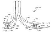
- FIG. 6 dis a partial perspective view of another prosthetic foot having an energy transfer medium with variable viscosity fluid in accordance with another embodiment of the present invention.
- FIG. 7is a side view of another prosthetic foot having an energy transfer medium with variable viscosity fluid in accordance with another embodiment of the present invention.
- FIG. 8 ais a side view of another prosthetic foot having an energy transfer mechanism or a variable resistance cell in accordance with another embodiment of the present invention.
- FIG. 8 bis a side view of another prosthetic foot having an energy transfer mechanism or a variable resistance cell in accordance with another embodiment of the present invention.
- FIG. 9 ais a side view of another prosthetic foot having an energy transfer mechanism or a variable resistance cell in accordance with another embodiment of the present invention.
- FIG. 9 bis a side view of another prosthetic foot having an energy transfer mechanism or a variable resistance cell in accordance with another embodiment of the present invention.
- FIG. 10is a side view of another prosthetic foot having an energy transfer mechanism or a variable resistance cell in accordance with another embodiment of the present invention.
- FIG. 11is a side view of another prosthetic foot having an energy transfer mechanism or a variable resistance cell in accordance with another embodiment of the present invention.
- FIG. 12is a side view of another prosthetic foot having an energy transfer mechanism or a variable resistance cell in accordance with another embodiment of the present invention.
- FIG. 13is a side view of another prosthetic foot having an energy transfer mechanism or a variable resistance cell in accordance with another embodiment of the present invention.
- FIG. 14is a side view of another prosthetic foot having an energy transfer mechanism or a variable resistance cell in accordance with another embodiment of the present invention.
- FIG. 15is a side view of another prosthetic foot having an energy transfer mechanism or a variable resistance cell in accordance with another embodiment of the present invention.
- FIG. 16is a side view of another prosthetic foot having an energy transfer mechanism or a variable resistance cell in accordance with another embodiment of the present invention.
- an energy transfer mediumthat includes a variable viscosity fluid or material, or an energy transfer mechanism.
- the energy transfer medium, or variable viscosity fluid or materialis located between first and second members of the foot so that energy is transferred between the first and second member, and thus through the energy transfer medium, during use.
- the variable viscosity of the fluid or materialallows the energy transferred between the members to be varied, thus varying the stiffness or response of the foot.
- the variable viscosity fluidcan increase in viscosity with an increase in a load factor applied to the variable viscosity fluid.
- variable viscosity fluid or materialcan include a shear stiffening material that increases in viscosity as load or strain, or load rate or strain rate, is applied; an electro rheologic fluid that changes viscosity under an applied electric field; or a magneto rheologic fluid that changes viscosity under an applied magnetic field.
- the energy transfer mechanism or variable resistance cellis disposed between primary and secondary foot members defining elongated springs.
- a prosthetic foot deviceindicated generally at 10 , in accordance with the present invention is shown with a variable energy transfer medium 14 for varying the stiffness or response of the foot device 10 .
- the foot device 10includes first and second members 18 and 22 .
- the first member 18is coupled to a stump of an amputee as is understood in the art, while the second member 22 is coupled to the first member 18 , and positioned to operate between the first member and the ground.
- the first member 18can be sized and shaped as a forefoot or upper foot member that extends from an attachment portion 26 , which is coupled to a stump of an amputee, downwardly and forwardly through an arcuate portion 30 , to a coupling section 34 coupled to the second member 22 .
- the second member 22can be sized and shaped as a full-length sole or lower foot member that extends from a heel portion 38 , through a coupling section 42 coupled to the first member 18 , to a toe portion 44 . It is believed that the configuration of the second member 22 as a full-length lower foot member provides a smoother gait.
- the attachment portion 26 of the first member 18can attach to a socket for receiving the stump of the amputee, as is known in the art.
- the socketis configured for the specific needs of the amputee, but typically has a portion adapted for standard attachment.
- the attachment portion 26can be attached to the socket by any means, such as by nut and bolt, again as is known in the art.
- the first member 18can be curved in a general C-shape, with the socket attaching to a top of the attachment portion 26 forming a horizontal attachment.
- a first membercan be curved in a general L-shape or a J-shape, with the socket attaching to the side of the attachment portion forming a vertical attachment, as shown in dashed lines in FIG. 2 .
- the heel portion 38 of the second member 22can be located at a heel location in a region near the rear of the foot device 10 where the heel of a natural foot would be located.
- the toe portion 44is located at a toe location in a region near the front of the foot device 10 where the toes of a natural foot would be located.
- the first and second members 18 and 22can be resilient and energy storing foot members that deflect or flex, storing energy, much like a leaf spring.
- the first and second members 18 and 22can be formed of a flexible and resilient material that allows the foot members to deflect or flex.
- the members 18 and 22can be formed of a fiber reinforced resin material, such as a graphite-reinforced resin.
- the first member 18can be disposed above, and spaced-apart from, the second member 22 , such that the members 18 and 22 are in a non-contacting relationship, or are not directly attached.
- the energy transfer medium 14can be disposed between, and can separate, the members 18 and 22 .
- the energy transfer medium 14can be more flexible than the energy-storing members 18 and 22 , and allows the members 18 and 22 to move with respect to one another.
- the energy transfer medium 14allows the members 18 and 22 to deflect or flex, and allows a greater range of motion of the members.
- the energy transfer medium 14can include a resilient and compliant material, such as rubber or urethane.
- the energy transfer medium 14can provide a cushioned, softer, and less stiff feel to the foot device 10 , making the foot device more comfortable and natural.
- the addition of the energy transfer medium 14also advantageously allows the first and second members 18 and 22 to be stiffer and stronger, while still providing a softer, cushioned feel.
- the stiffer stronger members 18 and 22can be more durable.
- the energy transfer medium 14also advantageously includes a variable viscosity fluid or material 50 .
- the variable viscosity fluid 50can be included in pockets or cavities formed in the energy transfer medium, as shown in FIG. 1 , or can form substantially the entire energy transfer medium, as shown in FIG. 2 .
- the energy transfer medium 14 and/or the variable viscosity fluid 50transfer energy from the second member 22 to the first member 18 during use, as described in greater detail below.
- the variable viscosity fluid or material 50can be disposed or contained in flexible bags or bladders 54 .
- variable viscosity fluid or material 50can include a shear stiffening material 60 .
- a shear stiffening material 60increases in viscosity as a load or strain (or load or strain rate) is applied, or as the load or strain increases.
- An example of such shear stiffening materialis a composition of cornstarch and water. Under little or no load or strain (indicated by arrow 64 ), the shear stiffening material 60 can be less viscous and capable of greater flow, and thus can be displacable while the energy transfer medium can be compressible, as shown in FIG. 2 c.
- the shear stiffening material 60can be more viscous and less capable of flowing, and thus can be less displacable while the energy transfer medium can be less compressible, as shown in FIG. 2 d. It will be appreciated that the less-viscous shear stiffening material dissipates more energy or force so that less energy or force is transferred by the material. Similarly, the more-viscous shear stiffening material transfers more energy or force.
- the variable viscosity fluid or material 50can include an electro rheologic fluid 70 that is responsive to an applied electric field to alter its viscosity.
- an electro rheologic fluid 70increases in viscosity as an electric field is applied.
- the electro rheologic fluid 70can be less viscous and capable of greater flow, and thus can be displacable, as shown in FIG. 2 f.
- the electro rheologic fluid 70can be more viscous and less capable of flowing, and thus can be less displacable, as shown in FIG. 2 g.
- the less-viscous electro rheologic fluiddissipates more energy or force so that less energy or force is transferred by the fluid.
- the more-viscous electro rheologic fluidtransfers more energy or force.
- the foot device 10can include a transducer 74 , such as a strain gauge, coupled to the first and/or second member 18 and/or 22 .
- the transducer 74senses strain or deformation in the member 18 and/or 22 .
- the transducer 74can be operatively coupled to control electronics 78 and a power source 82 .
- the control electronics 78 and transducer 74can be operatively coupled to the electro rheologic fluid, such as by electrodes 86 ( FIG. 2 e ) coupled to the bag 54 .
- the control electronics 78can include amplifier circuitry, while the power source 82 can be a battery.
- the transducer 74senses deflection or strain in the first and/or second members 18 and 22 and produces a signal that can be sent to the control electronics 78 .
- the control electronics 78can include amplifier circuitry to amplify the signal to create a control signal.
- the control electronics 78can include circuitry to accept only signals that correspond to a predetermined minimum strain or deflection.
- the control signalcan be applied to the electro rheologic fluid 70 by the electrodes 86 ( FIG. 2 e ). It will be appreciated that the control electronics 78 can include inputs to vary the amplification, minimums, etc., to control or customize the energy transfer of the fluid, and the stiffness of the foot device.
- the transducer 74can be coupled to the energy transfer medium 14 , or the bag or bladder 54 containing the variable viscosity fluid 50 .
- the transducer 74can be configured to sense pressure of the variable viscosity fluid 50 in the bladder 54 .
- the transducer 74can be configured to sense deflection of the energy transfer medium 14 .
- such an electro rheologic fluid 70can include particles or filings in an oil. As the electric field 88 is applied, the particles or filings align, increasing the viscosity of the fluid 70 , or the oil with particles or filings. With no or little electrical field 87 , the particles or filings are random, decreasing the viscosity of the fluid 70 , or the oil with particles or filings.
- variable viscosity fluid or material 50can include a magneto rheologic fluid 90 that is responsive to an applied magnetic field to alter its viscosity.
- a magneto rheologic fluid 90increases in viscosity as a magnetic field is applied.
- the magneto rheologic fluid 90can be less viscous and capable of greater flow, and thus can be displacable, as shown in FIG. 2 i.
- the magneto rheologic fluid 90Under a greater magnetic field (represented by lines 98 ), the magneto rheologic fluid 90 can be more viscous and less capable of flowing, and thus can be less displacable, as shown in FIG. 2 j.
- the less-viscous magneto rheologic fluiddissipates more energy or force so that less energy or force is transferred by the fluid.
- the more-viscous magneto rheologic fluidtransfers more energy or force.
- the magnetic fieldcan be applied by magnets 94 that are operatively coupled to the bag 54 .
- the magnets 94can be electromagnets operatively coupled to the control electronics 78 ( FIG. 2 ) using the control signal to generate the magnetic field.
- Such a magneto rheologic fluid 90can include particles or filings in an oil. As the magnetic field 98 is applied, the particles or filings align, increasing the viscosity of the fluid, or the oil with particles or filings. With little or no magnetic field 96 , the particles or filings are random, decreasing the viscosity of the fluid, or the oil with particles or filings.
- the electro rheologic fluid 70can be forced through, or can pass through, an orifice 100 and into a reservoir 102 under the loading of the foot.
- the electrodes 86can be disposed around the orifice 100 to apply and electric field at or near the orifice.
- the electro rheologic fluid 70is responsive to the applied electric field to alter its viscosity.
- Such an electro rheologic fluid 70increases in viscosity as the electric field is applied, thus impeding the flow of the fluid 70 through the orifice.
- the electro rheologic fluid 70Under little or no electric field (indicated at 87 ), the electro rheologic fluid 70 can be less viscous and capable of greater flow, and thus can pass through the orifice 100 , as shown in FIG.
- the fluid 70flows through the orifice 100 for less energy transfer, and a softer feel.
- the electro rheologic fluid 70can be more viscous and less capable of flowing, and thus is impeded from flowing through the orifice 100 , as shown in FIG. 2 l. Therefore, under greater force or load 66 , the fluid 70 is impeded from flowing through the orifice 100 for more energy transfer and a stiffer feel.
- the magneto rheologic fluid 90can be forced through, or can pass through, an orifice 100 and into a reservoir 102 under the loading of the foot.
- the magnets 94can be disposed around the orifice 100 to apply a magnetic field at or near the orifice.
- the magneto rheologic fluid 90is responsive to the applied magnetic field to alter its viscosity. Such a magneto rheologic fluid 90 increases in viscosity as the magnetic field is applied, thus impeding the flow of the fluid 90 through the orifice.
- the magneto rheologic fluid 90Under little or no magnetic field (indicated at 96 ), the magneto rheologic fluid 90 can be less viscous and capable of greater flow, and thus can pass through the orifice 100 , as shown in FIG. 2 m. Therefore, under lesser force or load 64 , the fluid 90 flows through the orifice 100 for less energy transfer, and a softer feel. Under a greater magnetic field (indicated at 98 ), the magneto rheologic fluid 90 can be more viscous and less capable of flowing, and thus is impeded from flowing through the orifice 100 , as shown in FIG. 2 n. Therefore, under greater force or load 66 , the fluid 90 is impeded from flowing through the orifice 100 for more energy transfer and a stiffer feel.
- FIGS. 3 a - 3 dthe operation of the foot device 10 is illustrated, with a lower force application, such as walking, illustrated in FIGS. 3 a and 3 b, and with a higher force application, such as running, illustrated in FIGS. 3 c and 3 d.
- a lower force applicationsuch as walking
- a higher force applicationsuch as running
- FIGS. 3 c and 3 dthe operation of the foot device 10 is illustrated, with a lower force application, such as walking, illustrated in FIGS. 3 a and 3 b, and with a higher force application, such as running, illustrated in FIGS. 3 c and 3 d.
- an applied forcesuch as the user's weight
- the secondary member 22applies a force to the energy transfer medium 14 and variable viscosity fluid that may be a lesser force due to the operation of the foot device 10 in a walking application.
- the energy transfer medium 14compresses to a greater extent, dissipating some of the force, and transferring less force to the first member 18 .
- the energy transfer medium 14 or variable viscosity fluidallows the second member 22 or heel portion 38 to deflect and/or move with respect to the first member 18 , providing a soft, cushioned feel.
- the toe portion 44 of the second member 22deflects (indicated by the solid and dashed lines).
- the secondary member 22applies a force to the energy transfer medium 14 and variable viscosity fluid that may be a lesser force due to the operation of the foot device 10 in a walking application.
- the energy transfer medium 14compresses to a greater extend, dissipating some of the force, and transferring less force to the first member 18 .
- the energy transfer medium 14 or variable viscosity fluidallows the second member 22 or toe portion 44 to deflect and/or move with respect to the first member 18 , providing a soft, cushioned feel.
- variable viscosity fluidcan be a shear stiffening material that increases viscosity due to the applied load or strain.
- variable viscosity fluidcan be a magneto or electro rheologic fluid that increases viscosity due to the application of a magnetic or electric field corresponding to the strain or deflection sensed by the transducer.
- the energy transfer medium 14 or variable viscosity fluidtransfers the energy or force from the second member 22 to the first member 18 causing the first member 18 to deflect, indicated by the dashed and solid lines. Therefore, in a higher load application, or running, both the first and second members 18 and 22 can be more fully utilized.
- the toe portion 44 of the second member 22deflects (indicated by the solid and dashed lines).
- the secondary member 22applies a force to the energy transfer medium 14 and variable viscosity fluid that may be a greater force due to the operation of the foot device 10 in a running application.
- the energy transfer medium 14 and variable viscosity fluidtransfer more force to the first member 18 causing the first member 18 to deflect (indicated by the dashed and solid lines).
- both the first and second members 18 and 22can be more fully utilized.
- first and second members 18 and 22can be made of a resilient material, the members 18 and 22 act as springs and store the energy to be subsequently released. As the user lifts the foot 10 , the toe portion 44 of the foot 10 returns to its original position, pushing-off.
- the energy transfer medium 114can be similar to that described above, including a variable viscosity fluid or material.
- the foot device 110has first and second members 118 and 122 with a different configuration than that described above.
- the first member 118can be an upper or forefoot member with an attachment section 126 (horizontal shown in solid lines, vertical shown in dashed lines), curving downwardly and forwardly through a curvilinear spring or ankle section 130 , an arch section 134 , and a toe section 144 at a toe location of toes of a natural foot.
- the first member 118can have a general C-shape or a J-shape.
- the second member 122can be a lower heel member and can have an attachment section 142 attached to the arch section 134 of the first member 118 , and extending rearwardly towards a heel section 138 at a heel location of a natural heel.
- the first and second members 118 and 122can be resilient and energy storing foot members that deflect or flex, storing energy, and can be formed of a fiber reinforced resin material, such as a graphite-reinforced resin.
- the energy transfer medium 114can be disposed between the first and second members 118 and 122 , and can operate as described above.
- the foot device 210can include a first member 218 that can include both 1) an upper forefoot member 219 , and 2) a lower heel member 220 , as described above.
- the foot device 210can include a second member that can be a forefoot and/or heel reinforcement member 222 and/or 224 .
- the forefoot reinforcement member 224can have an attachment section attached to the first member 218 or socket, and extend downwardly and forwardly in a curvilinear fashion above the upper forefoot member 219 of the first member 218 .
- a forefoot energy transfer medium 228can be disposed between the first and second members 218 and 222 , or between the upper forefoot member 219 and the forefoot reinforcement member 222 .
- the lower heel reinforcement member 224can include an attachment section attached to the first member 218 or socket, and extend downwardly and rearwardly in a curvilinear fashion above the lower heel member 220 of the first member 218 .
- a heel energy transfer medium 232can be disposed between the first and second members 218 and 224 , or between the lower heel member 220 and the heel reinforcement member 224 .
- the various members 219 , 220 , 222 and 224can be resilient and energy storing foot members that deflect or flex, storing energy, and can be formed of a fiber reinforced resin material, such as a graphite-reinforced resin.
- a prosthetic foot 300is shown with adaptors to convert the prosthetic foot 300 into a prosthetic foot device 310 and 312 with a variable energy transfer medium.
- the prosthetic foot 300 shown in FIGS. 6 and 7is similar to the prosthetic foot device shown in FIG. 4 and described above. It will be appreciated, however, that the adaptors can be used with various different configurations, such as those shown in FIGS. 2 and 5 .
- an adaptor 320is coupled to the prosthetic foot 300 such that the adaptor 320 forms a first member 322 , and the prosthetic foot 300 forms the second member 324 .
- the foot 300can be resilient and energy storing foot member that deflects or flexes, storing energy, and can be formed of a fiber reinforced resin material, such as a graphite-reinforced resin.
- the adaptor 320can attach in a horizontal manner to a horizontal attachment section of the prosthetic foot, as shown in solid lines, or in a vertical manner to a vertical attachment section of the prosthetic foot, as show in dashed lines.
- the adaptor 320can include a bracket 330 pivotally coupled to the foot 300 or attachment section.
- the bracket 330can include a base 332 and a pair of arms 334 extending therefrom with distal ends pivotally coupled to the foot 300 .
- An energy transfer medium 338 similar to those described above with a variable viscosity fluid or materialcan be disposed between the first member 322 or adaptor 320 and the second member 324 or foot 300 . Therefore, the adaptor 320 advantageously adds the energy transfer medium 338 to the prosthetic foot 300 .
- an adaptor 360is shown that is similar to the adaptor shown in FIG. 6 a, and described above.
- the adaptor 360further includes an attachment plate 364 for attachment to the foot 300 .
- the foot 300can be resilient and energy storing foot member that deflects or flexes, storing energy, and can be formed of a fiber reinforced resin material, such as a graphite-reinforced resin.
- the adaptor 360can include a similar base 368 with arms 372 extending therefrom and pivotally attached to the attachment plate 364 .
- An energy transfer medium 376is disposed between the base 368 and the attachment plate 364 .
- the adaptor 360can be coupled to the foot without having a pivotal attachment directly on the foot itself.
- an adaptor 400is shown that is similar in many respects to the adaptors described above.
- the adaptor 400advantageously can allow the foot or members to pivot in both 1) a longitudinal (or forward and rearward) direction, and 2) a lateral direction.
- the adaptor 400can include an attachment plate 402 for attachment to the foot, similar to that described above.
- the adaptorcan include a base 404 that is coupled to the attachment plate 402 , such is by a pin, so that the base 404 and the attachment member 402 can pivot with respect to one another.
- An energy transfer medium 408similar to those described above, can be disposed between the base 404 and the attachment plate 402 .
- the energy transfer medium 408can be disposed in various configurations, including in longitudinal and lateral alignment, as shown FIG. 6c , or in opposite corners, as shown in FIG. 6 d.
- the energy transfer medium 414can be similar to that described above, including a variable viscosity fluid or material.
- the foot device 410also includes first and second members 418 and 422 with a different configuration than that described above.
- the first member 418can be an upper attachment member with an attachment section 426 for coupling to a stump of an amputee.
- the second member 422can include a lower foot member with an attachment section 440 curving both 1) downwardly and forwardly to a toe section 444 at a toe location of toes of a natural foot, and 2) downwardly and rearwardly to a heel section 438 at a heel location of a natural heel.
- the second member 422can be pivotally attached to the first member 418 , such as with a pivot pin 450 .
- the second member 422can be resilient and energy storing foot member that deflects or flexes, storing energy, and can be formed of a fiber reinforced resin material, such as a graphite-reinforced resin.
- the energy transfer medium 414can be disposed between the first and second members 418 and 422 , and can operate as described above.
- the second member 440can pivot about the pivot pin 450 with respect to the first member 418 .
- the energy transfer medium 414can include a variable viscosity fluid as described above to adjust the feel or softness of the foot.
- prosthetic foot devicesare shown with an energy transfer mechanism or variable resistance cell that variably resists flow of a fluid through a variable orifice.
- the energy transfer mechanism or variable resistance cellcan be disposed between primary and secondary foot members that define primary and secondary elongated springs.
- the primary foot membercan be a forefoot member extending to a toe location of a natural toe and/or a heel member extending to a heel location of a natural heel
- the secondary foot membercan be a forefoot reinforcement member and/or a heel reinforcement member.
- the primary foot memberAs an applied load is applied to the primary foot member (such as the heel member and/or forefoot member) the primary foot member defines a spring that deflects and stores energy, and provides a resistance response to the applied force.
- the primary and secondary foot members, including the forefoot member, the forefoot reinforcement member, the heel member and the heel reinforcement membercan be formed of a composite material, such as a carbon fiber in a resin matrix.
- the energy transfer mechanism or variable resistance cellvariably transfers energy to the secondary foot member (such as the heel and/or forefoot reinforcement members).
- the secondary foot memberalso defines a spring, and thus deflects and stores energy, and provides an additional resistance response. Therefore, the overall resistance response applied by the foot (and stiffness or feel of the foot) is a combination of the primary and secondary foot members, and varies based on the amount of energy or applied load transferred from the primary foot member to the secondary foot member by the energy transfer mechanism or variable resistance cell.
- the energy transfer mechanism or variable resistance cellis configured to transfer a greater amount of energy or load from the primary to the secondary foot member in response to a greater applied load, thus providing a stiffer feel and greater resistance response.
- the variable orificecan reduce in size to increase resistance to the flow of fluid.
- variable resistance cellis configured to transfer a lesser amount or energy or load from the primary to the secondary foot member in response to a lesser applied load, thus providing a softer feel and a lesser resistance response.
- variable orificecan increase in size to decrease resistance to the flow of fluid.
- the foot device 510can include a primary elongated foot or forefoot member 518 and a secondary foot or reinforcement member 522 .
- the primary elongated foot member 518can be attached to the stump of an amputee, and can extend therefrom to a toe location of a natural toe, and can form an elongated resilient spring that can store energy during deflection and resist forces applied to the primary foot member 518 .
- the secondary foot member 522can also be an elongated resilient spring that can store energy during deflection and can be adjacent to and receive applied loads from the primary foot member 518 .
- the secondary foot or reinforcement member 522can be attached to the stump of an amputee and/or coupled to the primary foot member, and can extend above the primary foot member, as shown.
- the foot devicecan include means for variably transferring energy between the primary foot member 518 and the secondary foot member 522 during use.
- the means for variably transferring energycan increase resistance against the forces applied to the primary foot member 518 when the forces increase so that more load can be transferred between the primary foot member 518 and the secondary foot member 522 .
- the means for variably transferring energycan also decrease resistance against the forces applied to the primary foot member 518 when the forces decrease so that less load is transferred between the primary foot member 518 and the secondary foot member 522 .
- the means for variably transferring energycan be disposed between the primary elongated foot member 518 and the secondary foot member 522 , and can include an enclosure 532 disposed between the primary foot member 518 and the secondary foot member 522 , and a fluid path 536 that is in fluid communication with the enclosure 532 .
- the fluid path 536can also be in fluid communication with a reservoir 566 .
- a fluidcan be disposed in the enclosure 532 and reservoir 566 so that fluid can flow between the enclosure 532 , and the reservoir 566 , through the fluid path 536 .
- the fluidcan be a substantially incompressible fluid, such as oil.
- the fluidcan be a variable viscosity fluid as discussed above.
- the means for variably transferring energycan also include means for variably resisting fluid flow between the enclosure 532 and the reservoir 566 so that the force applied to the primary foot member 518 can be variably transferred to the secondary foot member 522 .
- the means for variably resisting fluid flowcan include a variable orifice 552 operatively disposed in the fluid path 536 and can provide variable resistance against fluid flow through the fluid path 536 .
- the variable orifice 552can be any variably sizable flow restriction device such as a servo-valve, a check valve, a needle valve, or a gate valve, as is generally known in the art.
- the variable orifice 552can variably resist the flow of fluid out of the enclosure 532 so that the enclosure can variably transfer energy between the primary elongated foot member 518 and the secondary foot member 522 during use.
- the variable orifice 552can increase resistance to fluid flow between the enclosure 532 and the reservoir 566 with an increase in the applied force to transfer more load or force between the primary foot member 518 and the secondary foot member 522 during an increase in the load or force applied to the primary foot member 518 .
- the variable orifice 552can decrease resistance to fluid flow during a decrease in the applied force to transfer less load or force between the primary foot member 518 and the secondary foot member 522 when the load factor on the primary foot member 518 decreases.
- the prosthetic foot device 510can have a stiffer feel to the user. Conversely, when a smaller load is applied to the primary foot member 518 , the variable orifice 552 allows more fluid to flow to the reservoir 566 so that more energy is absorbed by the enclosure 536 and less energy is transferred to the secondary foot member 522 . Thus, the prosthetic foot device 510 can have a softer feel to the user under low load conditions.
- the enclosure 532can be formed by a chamber 554 and a piston 556 as shown in FIG. 8 a, or a flexible bladder 562 as shown in FIG. 8 b.
- the enclosure 532can be compressible between the primary foot member 518 and the secondary foot member 522 . Additionally, the enclosure 532 can be compressible between a first position in response to a relatively larger load and a second position in response to a relatively smaller load.
- the enclosure 532 in the first positioncan have a larger dimension, such as height, in which a lesser amount of the fluid passes through the variable orifice 552 into the reservoir 566 .
- the enclosure 532 in the second positioncan have a smaller dimension, such as height, in which a greater amount of fluid passes through the variable orifice 552 into the reservoir 566 .
- FIGS. 9 a and banother prosthetic foot device 610 ( FIG. 9 a ) or 612 ( FIG. 9 b ) is shown which is similar in many respects to the foot devices described above.
- the foot device 610can include a primary elongated forefoot member 618 , a secondary forefoot member 622 , a primary heel member 626 , and a secondary heel member 632 .
- the primary elongated foot member 618can be attached to the stump of an amputee, and can extend therefrom to a toe location of a natural foot forming an elongated resilient spring that can store energy during deflection and resist forces applied to the primary elongated foot member 618 .
- the secondary forefoot member 622can also be an elongated resilient spring that can store energy during deflection.
- the secondary forefoot member 622can also be coupled to the stump of an amputee, and/or the primary forefoot member 618 , and can extend above the primary forefoot member.
- the primary heel member 626can also be coupled to the stump of an amputee, or attached to the primary forefoot member 618 , and can extend therefrom to a heel location of a natural foot forming an elongated resilient spring that can store energy during deflection and resist forces applied to the primary heel member 626 .
- the secondary heel member 632can also be an elongated resilient spring that can store energy during deflection, and can be adjacent to and receive applied loads from the primary heel member 626 .
- the secondary heel member 632can be coupled to the stump of the amputee, the primary forefoot member 618 , and/or the primary heel member 626 , and can extend above the primary heel member.
- the foot device 610(or 612 ) can include a first enclosure 636 , disposed between the primary forefoot member 618 and the secondary forefoot member 622 , and a second enclosure 642 disposed between the primary heel member 626 and the secondary heel member 632 .
- the first enclosure 636 and second enclosure 642can be fluidly connected by a fluid path 646 .
- a fluidcan be disposed in the first and second enclosures 636 and 642 so that fluid can flow between the first and second enclosures 636 and 642 through the fluid path 646 .
- the second enclosurecan form a reservoir for the first enclosure
- the first enclosurecan form a reservoir for the second enclosure.
- a variable orifice 652can be operatively disposed in the fluid path 646 to provide variable resistance against fluid flow therethrough.
- the variable orifice 652can have a variable size to provide resistance against fluid flow through the fluid path 646 , to variably transfer the applied force from the primary forefoot member 618 to the secondary forefoot member 622 , and from the primary heel member 626 to the secondary heel member 632 .
- the variable orifice 652can variably transfer fluid between the first enclosure 636 and the second enclosure 642 during use.
- the variable orifice 652can increase resistance to fluid flow between the first enclosure 636 and the second enclosure 642 with an increase in the applied force to transfer more load between the primary forefoot member 618 and secondary forefoot member 622 , or the primary heel member 626 and the secondary heel member 632 , during the increase in the applied force.
- variable orifice 652can also decrease resistance to fluid flow during a decrease in the applied force to transfer less load between the primary forefoot member 618 and the secondary forefoot member 622 , or the primary heel member 626 and secondary heel member 632 , during the decrease the applied force.
- the first and second enclosures 636 and 642can each be formed by chambers 656 and pistons 656 as shown in FIG. 9 a, or flexible bladders 662 as shown in FIG. 9 b.
- the first enclosure 636can be compressible between the primary foot member 618 and the secondary foot member 622 .
- the second enclosure 642can be compressible between the primary heel member 626 and the secondary heel member 632 . Additionally, the first and second enclosures 636 and 642 can be compressible between a first position in response to a relatively larger load or force, and a second position in response to a relatively smaller load or force.
- the first and second enclosures 636 and 642 in the first positioncan have a larger dimension, such as height, in which a lesser amount of the fluid passes through the variable orifice 652 .
- the first and second enclosures 636 and 642 in the second positioncan have a smaller dimension, such as height, in which a greater amount of fluid passes through the variable orifice 652 .
- the foot device 710can include a primary elongated forefoot member 718 , a secondary forefoot member 722 , a primary heel member 726 , and a secondary heel member 732 .
- the primary foot member 718can be attached to the stump of an amputee, and extend therefrom to a toe location of a natural foot forming an elongated resilient spring that can store energy during deflection and resist forces applied to the primary elongated foot member 718 .
- the secondary forefoot member 722can be coupled to the stump of the amputee and/or the primary forefoot member, and can also be an elongated resilient spring that can store energy during deflection and can be adjacent to and receive applied loads from the primary forefoot member 718 .
- the primary heel member 726can also be attached to the stump of an amputee and/or the primary forefoot member 718 , and can extend therefrom to a heel location of a natural foot forming an elongated resilient spring that can store energy during deflection and resist forces applied to the primary heel member 726 .
- the secondary heel member 732can be coupled to the stump of the amputee, the primary forefoot member and/or the primary heel member, and can also be an elongated resilient spring that can store energy during deflection, and can be adjacent to and receive applied loads from the primary heel member 726 .
- the foot device 710can include a first enclosure 736 , disposed between the primary forefoot member 718 and the secondary forefoot member 722 , and a second enclosure 742 disposed between the primary heel member 726 and the secondary heel member 732 .
- the first enclosure 736can be fluidly connected to a first fluid path 746
- the second enclosure 742can be fluidly connected to a second fluid path 748 .
- the first fluid path 746can also be connected to a first reservoir 766
- the second fluid path 748can be connected to a second reservoir 772 .
- a fluidcan be disposed in the first and second enclosures 736 and 742 so that fluid can flow between the first and second enclosures 736 and 742 through the first and second fluid paths 746 and 748 to the first and second reservoirs 766 and 772 , respectively.
- a first variable orifice 752can be operatively disposed in the first fluid path 746 to provide variable resistance against fluid flow through the first fluid path 746 .
- a second variable orifice 754can be operatively disposed in the second fluid path 748 to provide variable resistance against fluid flow through the second fluid path 748 .
- the first and second variable orifices 752 and 754can provide resistance against fluid flow through the first and second fluid paths 746 and 748 , respectively, to variably transfer the applied force from the primary forefoot member 718 to the secondary forefoot member 722 , and from the primary heel member 726 to the secondary heel member 732 .
- the first variable orifice 752can variably transfer fluid between the first enclosure 736 and the first reservoir 766 during use.
- the second variable orifice 754can variably transfer fluid between the second enclosure 748 and the second reservoir during use 772 .
- the use of two variable orifices, or different variable orifices for the forefoot and heelallows the stiffness or feel of the forefoot and heel to be independently controlled or varied.
- the first and second enclosures 736 and 742can each be formed by chambers and pistons 756 , as shown in FIG. 10 , or flexible bladders as described above.
- the first enclosure 736can be compressible between the primary foot member 718 and the secondary foot member 722 .
- the second enclosure 742can be compressible between the primary heel member 726 and the secondary heel member 732 . Additionally, the first and second enclosures 736 and 742 can be compressible between a first position in response to a relatively larger load or applied force and a second position in response to a relatively smaller load or applied force.
- the first and second enclosures 736 and 742 in the first positioncan have a larger dimension, such as height, in which a lesser amount of the fluid passes through the first and second variable orifices 752 and 754 .
- the first and second enclosures 736 and 742 in the second positioncan have a smaller dimension, such as height, in which a greater amount of fluid passes through the first and second variable orifices 752 and 754 .
- the foot device 810can include a primary elongated forefoot member 818 , a secondary forefoot member 822 , a primary heel member 826 , and a secondary heel member 832 .
- the foot device 810can also include a first enclosure 836 , disposed between the primary forefoot member 818 and the secondary forefoot member 822 , and a second enclosure 842 disposed between the primary heel member 826 and the secondary heel member 832 .
- the first enclosure 836can be fluidly connected to a first fluid path 846
- the second enclosure 842can be fluidly connected to a second fluid path 848 .
- the first and second fluid paths 846 and 848can also be connected to a reservoir 866 .
- a fluidcan be disposed in the first and second enclosures 836 and 842 so that fluid can flow between the first and second enclosures 836 and 842 through the first and second fluid paths 846 and 848 to the reservoir 866 .
- a first variable orifice 852can be operatively disposed in the first fluid path 846 to provide variable resistance against fluid flow through the first fluid path 846 .
- a second variable orifice 854can be operatively disposed in the second fluid path 848 to provide variable resistance against fluid flow through the second fluid path 848 .
- the first and second variable orifices 852 and 854can provide resistance against fluid flow through the first and second fluid paths 846 and 848 , respectively, to variably transfer the applied force from the primary forefoot member 818 to the secondary forefoot member 822 , and from the primary heel member 826 to the secondary heel member 832 .
- the first variable orifice 852can variably transfer fluid between the first enclosure 836 and the reservoir 866 during use.
- the second variable orifice 754can variably transfer fluid between the second enclosure 748 and the reservoir 866 during use.
- the foot device 910can include a primary elongated forefoot member 918 , a secondary forefoot member 922 , a primary heel member or foot plate 926 , and a secondary heel member 932 .
- the primary foot member 918can be attached to the stump of an amputee, and extend therefrom to a toe location of a natural foot forming an elongated resilient spring that can store energy during deflection and resist forces applied to the primary elongated foot member 918 .
- the secondary forefoot member 922can be coupled to the stump of the amputee and/or the primary forefoot member, and can also be an elongated resilient spring that can store energy during deflection and can be adjacent to and receive applied loads from the primary forefoot member 918 .
- the primary heel member 926can extend from a heel location of a natural heel to the primary forefoot member 918 , and can also be an elongated resilient spring that can store energy during deflection.
- the secondary heel member 932can be coupled to the stump of the amputee, the primary forefoot member and/or the primary heel member, and can also be an elongated resilient spring that can store energy during deflection, and can be adjacent to and receive applied loads from the primary heel member 926 .
- the various members 918 , 922 , 926 and 932can be resilient and energy storing foot members that deflect or flex, storing energy, and can be formed of a fiber reinforced resin material, such as a graphite-reinforced resin
- the foot device 910can include a first enclosure 936 , disposed between the primary forefoot member 918 and the secondary forefoot member 922 , and a second enclosure 942 disposed between the primary heel member 926 and the secondary heel member 932 .
- the first enclosure 936 and second enclosure 942can be fluidly connected by a fluid path 946 .
- a fluidcan be disposed in the first and second enclosures 936 and 942 so that fluid can flow between the first and second enclosures 936 and 942 through the fluid path 946 .
- a variable orifice 952can be operatively disposed in the fluid path 946 to provide variable resistance against fluid flow therethrough.
- the variable orifice 952can have a variable size to provide resistance against fluid flow through the fluid path 946 , to variably transfer the applied force from the primary forefoot member 918 to the secondary forefoot member 922 , and from the primary heel member 926 to both the secondary heel member 932 and the primary foot member 918 .
- the variable orifice 952can variably transfer fluid between the first enclosure 936 and the second enclosure 942 during use.
- the variable orifice 952can increase resistance to fluid flow between the first enclosure 936 and the second enclosure 942 with an increase in the applied force to transfer more load between the primary forefoot member 918 and secondary forefoot member 922 , or the primary heel member 926 and the secondary heel member 932 , during the increase in the applied force.
- variable orifice 952can also decrease resistance to fluid flow during a decrease in the applied force to transfer less load between the primary forefoot member 918 and the secondary forefoot member 922 , or the primary heel member 926 and secondary heel member 932 , during the decrease the applied force.
- the first and second enclosures 936 and 942can each be formed by chambers and pistons 956 , as shown in FIG. 12 , or flexible bladders as described above.
- the first enclosure 936can be compressible between the primary foot member 918 and the secondary foot member 922 .
- the second enclosure 942can be compressible between the primary heel member 926 and the secondary heel member 932 .
- the first and second enclosures 936 and 942can be compressible between a first position in response to a relatively larger load or applied force and a second position in response to a relatively smaller load or applied force.
- the first and second enclosures 936 and 942 in the first positioncan have a larger dimension, such as height, in which a lesser amount of the fluid passes through the variable orifice 952 .
- the first and second enclosures 936 and 942 in the second positioncan have a smaller dimension, such as height, in which a greater amount of fluid passes through the variable orifice 952 .
- first and second enclosures 936 and 942can have separate first and second reservoirs and separate first and second variable orifices.
- the foot device 1010can include a primary elongated foot or forefoot member 1018 and a secondary foot or reinforcement member 1022 .
- the primary elongated foot member 1018can be attached to the stump of an amputee, and can extend therefrom to a toe location of a natural toe, and can form an elongated resilient spring that can store energy during deflection and resist forces applied to the primary foot member 1018 .
- the secondary foot member 1022can also be an elongated resilient spring that can store energy during deflection and can be adjacent to and receive applied loads from the primary foot member 1018 .
- the secondary foot or reinforcement member 1022can be attached to the stump of an amputee and/or coupled to the primary foot member, and can extend above the primary foot member, as shown.
- the foot devicecan include means for variably transferring energy between the primary foot member 1018 and the secondary foot member 1022 during use.
- the means for variably transferring energycan increase resistance against the forces applied to the primary foot member 1018 when the forces increase so that more load can be transferred between the primary foot member 1018 and the secondary foot member 1022 .
- the means for variably transferring energycan also decrease resistance against the forces applied to the primary foot member 1018 when the forces decrease so that less load is transferred between the primary foot member 1018 and the secondary foot member 1022 .
- the means for variably transferring energycan be disposed between the primary elongated foot member 1018 and the secondary foot member 1022 , and can include variable resistance cell 1032 disposed between the primary foot member 1018 and the secondary foot member 1022 .
- the variable resistance cellcan include a chamber 1068 associated with one of the primary or secondary foot members.
- a piston 1064can be associated with another of the primary 1018 and secondary foot 1022 members.
- the piston 1064can be movable in the chamber 1068 .
- the piston 1064 and chamber 1068can define a volume that changes in response to the load factor.
- At least one aperture 1074can be formed through the piston and in communication with the chamber.
- the chamber and the pistoncan be displaceable with respect to one another between the first and second foot members.
- variable viscosity fluid 1012can be disposed in the chamber 1068 and can be displaceable through the at least one aperture 1074 in the piston 1064 in response to the load factor.
- the variable viscosity fluidcan remain between the first and second foot members.
- the variable viscosity fluid 1012can have a viscosity that is variable corresponding to the load factor to vary an ability of the variable viscosity fluid to flow through the at least one aperture.
- the cell 1032can also include a reservoir 1062 that can receive variable viscosity fluid from the chamber 1068 through the aperture 1074 .
- the reservoir 1062can be a flexible enclosure that can expand as fluid enters the reservoir.
- the reservoir 1062can include a separate enclosure 1069 such as a flexible bladder, as shown in FIG. 14 .
- the chamber 1068can be compressible between the primary foot member 1018 and the secondary foot member 1022 . Additionally, the chamber 1068 can be compressible between a first position in response to a relatively larger load and a second position in response to a relatively smaller load.
- the chamber 1068 in the first positioncan have a larger dimension, such as height, in which a lesser amount of the fluid passes through the aperture 1074 into the reservoir 1062 .
- the chamber 1068 in the second positioncan have a smaller dimension, such as height, in which a greater amount of fluid passes through the aperture 1074 into the reservoir 1062 .
- variable viscosity fluid 1012can include a magneto rheologic fluid responsive to a magnetic field, an electro rheologic fluid responsive to an electric field, or combinations of magneto and electro rhelogic fluids. Additionally, the variable viscosity fluid 1012 can also include a shear stiffening material that increases in viscosity with an increase in the load factor applied to the shear stiffening material.
- the load factorcan include at least one load factor from a load, a load rate, a load acceleration, a strain, a strain rate, a strain acceleration, a pressure, a pressure rate, a pressure acceleration, a deflection, a deflection rate, and a deflection acceleration.
- the cell 1032can also include a transducer 1078 to sense a load factor, and a power source 1080 , coupled to the transducer to power the variable viscosity fluid 1012 .
- Control electronicscan be coupled to the transducer 1078 and the variable viscosity fluid 1012 in order to apply an electric or magnetic field in response to the load factor sensed by the transducer.
- the control electronicscan be programmable, and the power source can include a generator.
- FIGS. 13-14can also be used with the feet described above.
- the foot device 1110can include a primary elongated forefoot member 1118 , a secondary forefoot member 1122 , a primary heel member 1126 , and a secondary heel member 1132 .
- the primary elongated foot member 1118can be attached to the stump of an amputee, and can extend therefrom to a toe location of a natural foot forming an elongated resilient spring that can store energy during deflection and resist forces applied to the primary elongated foot member 1118 .
- the secondary forefoot member 1122can also be an elongated resilient spring that can store energy during deflection.
- the secondary forefoot member 1122can also be coupled to the stump of an amputee, and/or the primary forefoot member 1118 , and can extend above the primary forefoot member.
- the primary heel member 1126can also be coupled to the stump of an amputee, or attached to the primary forefoot member 1118 , and can extend therefrom to a heel location of a natural foot forming an elongated resilient spring that can store energy during deflection and resist forces applied to the primary heel member 1126 .
- the secondary heel member 1132can also be an elongated resilient spring that can store energy during deflection, and can be adjacent to and receive applied loads from the primary heel member 1126 .
- the secondary heel member 632can be coupled to the stump of the amputee, the primary forefoot member 1118 , and/or the primary heel member 1126 , and can extend above the primary heel member.
- the foot device 1110can include a first variable resistance cell 1032 a, disposed between the primary forefoot member 1118 and the secondary forefoot member 1122 , and a second variable resistance cell 1032 b disposed between the primary heel member 1126 and the secondary heel member 1132 .
- the first cell 1032 a and second cell 1032 bcan be similar in structure and function to the cell 1032 described above and shown in FIGS. 13 and 14 .
- the foot device 1210can include a primary elongated forefoot member 1218 , a secondary forefoot member 1222 , a primary heel member or foot plate 1226 , and a secondary heel member 1232 .
- the primary foot member 1218can be attached to the stump of an amputee, and extend therefrom to a toe location of a natural foot forming an elongated resilient spring that can store energy during deflection and resist forces applied to the primary elongated foot member 1218 .
- the secondary forefoot member 1222can be coupled to the stump of the amputee and/or the primary forefoot member, and can also be an elongated resilient spring that can store energy during deflection and can be adjacent to and receive applied loads from the primary forefoot member 1218 .
- the primary heel member 1226can extend from a heel location of a natural heel to the primary forefoot member 1218 , and can also be an elongated resilient spring that can store energy during deflection.
- the secondary heel member 1232can be coupled to the stump of the amputee, the primary forefoot member and/or the primary heel member, and can also be an elongated resilient spring that can store energy during deflection, and can be adjacent to and receive applied loads from the primary heel member 1226 .
- the various members 1218 , 1222 , 1226 and 1232can be resilient and energy storing foot members that deflect or flex, storing energy, and can be formed of a fiber reinforced resin material, such as a graphite-reinforced resin
- the foot device 1210can include a first variable resistance cell 1032 c, disposed between the primary forefoot member 1218 and the secondary forefoot member 1222 , and a second variable resistance cell 1032 d disposed between the primary heel member 1226 and the secondary heel member 1232 .
- the first cell 1032 c and second cell 1032 dcan be similar in structure and function to the cell 1032 described above and shown in FIGS. 13 and 14 .
Landscapes
- Health & Medical Sciences (AREA)
- Transplantation (AREA)
- Biomedical Technology (AREA)
- Cardiology (AREA)
- Oral & Maxillofacial Surgery (AREA)
- Engineering & Computer Science (AREA)
- Heart & Thoracic Surgery (AREA)
- Vascular Medicine (AREA)
- Life Sciences & Earth Sciences (AREA)
- Animal Behavior & Ethology (AREA)
- General Health & Medical Sciences (AREA)
- Public Health (AREA)
- Veterinary Medicine (AREA)
- Orthopedic Medicine & Surgery (AREA)
- Prostheses (AREA)
Abstract
Description
Claims (25)
Priority Applications (6)
| Application Number | Priority Date | Filing Date | Title |
|---|---|---|---|
| US11/377,228US7572299B2 (en) | 2000-06-30 | 2006-03-15 | Prosthetic foot with energy transfer |
| PCT/US2006/013213WO2006108166A2 (en) | 2005-04-04 | 2006-04-04 | Prosthetic foot with energy transfer |
| DE112006000827TDE112006000827T5 (en) | 2005-04-04 | 2006-04-04 | Foot prosthesis with energy transfer |
| AU2006232485AAU2006232485A1 (en) | 2005-04-04 | 2006-04-04 | Prosthetic foot with energy transfer |
| IS8676AIS8676A (en) | 2006-03-15 | 2007-09-21 | Artificial foot with energy transfer equipment |
| US12/006,801US7686848B2 (en) | 2000-06-30 | 2008-01-04 | Prosthetic foot with energy transfer |
Applications Claiming Priority (5)
| Application Number | Priority Date | Filing Date | Title |
|---|---|---|---|
| US60749400A | 2000-06-30 | 2000-06-30 | |
| US10/137,933US6663673B2 (en) | 2000-06-30 | 2002-05-03 | Prosthetic foot with energy transfer medium including variable viscosity fluid |
| US10/738,645US6875242B2 (en) | 2000-06-30 | 2003-12-16 | Prosthetic foot with energy transfer medium including variable viscosity fluid |
| US11/098,828US7341603B2 (en) | 2000-06-30 | 2005-04-04 | Prosthetic foot with energy transfer including variable orifice |
| US11/377,228US7572299B2 (en) | 2000-06-30 | 2006-03-15 | Prosthetic foot with energy transfer |
Related Parent Applications (1)
| Application Number | Title | Priority Date | Filing Date |
|---|---|---|---|
| US11/098,828Continuation-In-PartUS7341603B2 (en) | 2000-06-30 | 2005-04-04 | Prosthetic foot with energy transfer including variable orifice |
Related Child Applications (1)
| Application Number | Title | Priority Date | Filing Date |
|---|---|---|---|
| US12/006,801Continuation-In-PartUS7686848B2 (en) | 2000-06-30 | 2008-01-04 | Prosthetic foot with energy transfer |
Publications (2)
| Publication Number | Publication Date |
|---|---|
| US20060229736A1 US20060229736A1 (en) | 2006-10-12 |
| US7572299B2true US7572299B2 (en) | 2009-08-11 |
Family
ID=37074124
Family Applications (1)
| Application Number | Title | Priority Date | Filing Date |
|---|---|---|---|
| US11/377,228Expired - Fee RelatedUS7572299B2 (en) | 2000-06-30 | 2006-03-15 | Prosthetic foot with energy transfer |
Country Status (4)
| Country | Link |
|---|---|
| US (1) | US7572299B2 (en) |
| AU (1) | AU2006232485A1 (en) |
| DE (1) | DE112006000827T5 (en) |
| WO (1) | WO2006108166A2 (en) |
Cited By (16)
| Publication number | Priority date | Publication date | Assignee | Title |
|---|---|---|---|---|
| US20090287315A1 (en)* | 2004-05-28 | 2009-11-19 | össur hf. | Foot prosthesis with resilient multi-axial ankle |
| US8034121B2 (en) | 2008-04-18 | 2011-10-11 | Freedom Innovations, Llc | Prosthetic foot with two leaf-springs joined at heel and toe |
| US8486156B2 (en) | 2010-02-26 | 2013-07-16 | össur hf | Prosthetic foot with a curved split |
| US8500825B2 (en) | 2010-06-29 | 2013-08-06 | Freedom Innovations, Llc | Prosthetic foot with floating forefoot keel |
| US8961618B2 (en) | 2011-12-29 | 2015-02-24 | össur hf | Prosthetic foot with resilient heel |
| US9078773B2 (en) | 2007-09-19 | 2015-07-14 | Ability Dynamics Llc | Prosthetic foot |
| US9561118B2 (en) | 2013-02-26 | 2017-02-07 | össur hf | Prosthetic foot with enhanced stability and elastic energy return |
| USD795433S1 (en) | 2015-06-30 | 2017-08-22 | Össur Iceland Ehf | Prosthetic foot cover |
| USD797292S1 (en) | 2014-06-30 | 2017-09-12 | össur hf | Prosthetic foot plate |
| US9999525B2 (en) | 2015-01-15 | 2018-06-19 | Ability Dynamics, Llc | Prosthetic foot |
| US10405998B2 (en) | 2007-09-19 | 2019-09-10 | Ability Dynamics Llc | Mounting bracket for connecting a prosthetic limb to a prosthetic foot |
| USD915596S1 (en) | 2018-04-10 | 2021-04-06 | Össur Iceland Ehf | Prosthetic foot with tapered fasteners |
| US11020248B2 (en) | 2007-09-19 | 2021-06-01 | Proteor USA, LLC | Vacuum system for a prosthetic foot |
| US12011373B2 (en) | 2007-09-19 | 2024-06-18 | Proteor USA, LLC | Mounting bracket for connecting a prosthetic limb to a prosthetic foot |
| WO2025132398A1 (en) | 2023-12-19 | 2025-06-26 | Otto Bock Healthcare Products Gmbh | Orthopaedic device and hydraulic system |
| US12365145B2 (en) | 2023-03-24 | 2025-07-22 | Erdman Automation Corporation | Mesh to flexible screen frame laminator |
Families Citing this family (6)
| Publication number | Priority date | Publication date | Assignee | Title |
|---|---|---|---|---|
| US8016892B2 (en) | 2005-06-10 | 2011-09-13 | The Ohio Willow Wood Company | Prosthetic device utilizing electric vacuum pump |
| US8652217B2 (en)* | 2005-06-10 | 2014-02-18 | The Ohio Willow Wood Company | Prosthetic device utilizing electric vacuum pump |
| EP2522311B1 (en)* | 2009-11-25 | 2016-07-06 | Otto Bock HealthCare GmbH | Prosthetic foot |
| US20120179274A1 (en)* | 2010-07-13 | 2012-07-12 | Christensen Roland J | Bifurcated, multi-purpose prosthetic foot |
| DE102010043333B4 (en)* | 2010-11-03 | 2014-10-23 | Deutsches Zentrum für Luft- und Raumfahrt e.V. | Flexible element |
| WO2020012319A1 (en)* | 2018-07-10 | 2020-01-16 | Comité International De La Croix-Rouge (Cicr) | Prosthetic foot |
Citations (151)
| Publication number | Priority date | Publication date | Assignee | Title |
|---|---|---|---|---|
| US42799A (en) | 1864-05-17 | Improvement in artificial legs | ||
| US92031A (en) | 1869-06-29 | Improved artificial leg | ||
| US292800A (en) | 1884-02-05 | Artificial leg | ||
| US497026A (en) | 1893-05-09 | Artificial limb | ||
| US1001641A (en) | 1909-03-17 | 1911-08-29 | John Waddell | Ankle-joint. |
| US1191633A (en) | 1916-01-26 | 1916-07-18 | J H White Mfg Company | Resilient attachment for shade-holders. |
| US1289580A (en) | 1918-04-05 | 1918-12-31 | Stanislaw Vincenti | Artificial foot. |
| US1779765A (en) | 1926-09-21 | 1930-10-28 | Firm Of F L Fischer | Artificial-foot joint |
| US1996874A (en) | 1932-08-31 | 1935-04-09 | Mascau Emile Desire | Articulated ankle joint for artificial feet |
| US2036830A (en) | 1934-08-13 | 1936-04-07 | James F Rowley | Artificial foot |
| US2101265A (en) | 1934-01-09 | 1937-12-07 | Mercier Jean | Shock absorber |
| US2379538A (en) | 1942-09-09 | 1945-07-03 | Meierhofer Max | Joint for leg supports and artificial limbs in general |
| US2443356A (en) | 1946-04-02 | 1948-06-15 | John H Mathis | Flexible joint for artificial limbs |
| US2453969A (en) | 1947-04-03 | 1948-11-16 | Edwin C Carter | Artificial limb |
| US2470480A (en) | 1946-04-23 | 1949-05-17 | Stanley R Fogg | Artificial foot |
| US2570735A (en) | 1949-03-18 | 1951-10-09 | Carl A Weise | Flexible joint for artificial limbs |
| US2617115A (en) | 1949-07-25 | 1952-11-11 | Emmett C Ellery | Ankle joint for artificial legs |
| US2640200A (en) | 1950-07-28 | 1953-06-02 | Wisbrun Walter | Prosthesis construction |
| US2843853A (en) | 1956-11-26 | 1958-07-22 | Hans A Mauch | Control mechanism for artificial ankle |
| US2973969A (en) | 1955-05-11 | 1961-03-07 | Earle S Thall | Electrical shock absorbing system |
| US3206235A (en) | 1962-08-30 | 1965-09-14 | Miller Herman Inc | Adjustable foot piece |
| US3379430A (en) | 1966-01-17 | 1968-04-23 | W E Hennells Company Inc | Twin piston pneumatic spring |
| GB1191633A (en) | 1966-06-14 | 1970-05-13 | J E Hanger And Company Ltd | Improvements in Artificial Limbs and Splints |
| US3548420A (en) | 1967-03-06 | 1970-12-22 | Stryker Corp | Cushion structure |
| US3551914A (en) | 1968-05-09 | 1971-01-05 | Carl Woodall | Natural action toe lift artificial foot |
| US3754286A (en) | 1972-01-21 | 1973-08-28 | M Ryan | Artificial foot having ankle flexible mount |
| US3858379A (en) | 1970-06-09 | 1975-01-07 | Us Army | Process for making a polyvinyl alcohol gel support pad |
| US3871032A (en) | 1974-03-08 | 1975-03-18 | Forsch Orthopadie Technik | Artificial hydraulic ankle joint |
| US3874004A (en) | 1973-05-31 | 1975-04-01 | Hanger & Co Ltd J E | Symes ankle joint |
| US3906552A (en) | 1972-08-30 | 1975-09-23 | Watkins Lloyd J | Pivot joint adapter |
| US3920610A (en) | 1973-02-28 | 1975-11-18 | Eugene Wagner | Method of making and tailoring prosthetic feet |
| US3956775A (en) | 1975-02-18 | 1976-05-18 | Moore Robert R | Rotator for prosthetic ankle joint |
| US3982280A (en) | 1973-05-03 | 1976-09-28 | The United States Of America As Represented By The Secretary Of The Navy | Functional ankle for a prosthetic limb |
| US4089072A (en) | 1975-07-18 | 1978-05-16 | Otto Bock Orthopadische Industrie K.G. | Prosthetic appliance |
| GB1550658A (en) | 1977-11-16 | 1979-08-15 | Hanger & Co Ltd J E | Artificial limbs |
| US4328594A (en) | 1980-02-13 | 1982-05-11 | Campbell John W | Prosthetic foot |
| US4442554A (en) | 1982-02-12 | 1984-04-17 | Arthur Copes | Biomechanical ankle device |
| US4506395A (en) | 1983-03-18 | 1985-03-26 | Otto Bock Orthopadische Industrie Kg | Prosthetic foot |
| US4547913A (en) | 1983-07-11 | 1985-10-22 | Flex Foot, Inc. | Composite prosthetic foot and leg |
| US4606332A (en) | 1984-09-10 | 1986-08-19 | Gibson Howard W | Back treatment apparatus |
| US4636220A (en) | 1986-01-14 | 1987-01-13 | John W. Campbell | Adjustable prosthetic foot |
| US4645509A (en) | 1984-06-11 | 1987-02-24 | Model & Instrument Development Corporation | Prosthetic foot having a cantilever spring keel |
| US4676800A (en) | 1986-06-02 | 1987-06-30 | Chen Sen J | Adjustable device for artificial limbs |
| US4676801A (en) | 1983-05-23 | 1987-06-30 | Orthopedic Specialties, Inc. | Foot orthosis and process |
| US4721510A (en) | 1986-02-28 | 1988-01-26 | J. E. Hanger & Company, Limited | Artificial foot |
| US4793450A (en) | 1985-05-09 | 1988-12-27 | Auping B. V. | Lockable piston-cylinder assembly |
| US4822363A (en) | 1985-08-01 | 1989-04-18 | Phillips L Van | Modular composite prosthetic foot and leg |
| US4852863A (en) | 1987-08-22 | 1989-08-01 | Robert Bosch Gmbh | Pneumatic suspension for motor vehicles |
| US4865612A (en) | 1986-07-28 | 1989-09-12 | The Ohio Willow Wood Company, Inc. | Prosthetic foot |
| US4865611A (en) | 1988-05-16 | 1989-09-12 | Al Turaiki Mohammed H S | Lockable rotating ankle joint for modular below-knee prosthesis |
| US4869476A (en) | 1988-08-09 | 1989-09-26 | Trw Inc. | Electrically controlled viscous elastic spring |
| US4938775A (en) | 1989-04-03 | 1990-07-03 | Morgan Robert D | Artificial leg with bearings for rotational motion |
| US4959073A (en) | 1988-06-06 | 1990-09-25 | John Merlette | Foot prosthesis and method of making same |
| US4986393A (en) | 1988-02-09 | 1991-01-22 | Boge Ag | Adjustable vibration dampers for motor vehicles |
| US5019109A (en) | 1990-03-09 | 1991-05-28 | Voisin Jerome P | Multi-axial rotation system for artificial ankle |
| US5030239A (en) | 1982-02-12 | 1991-07-09 | Copes, Inc. | Biomechanical ankle |
| US5037444A (en) | 1989-01-05 | 1991-08-06 | Phillips L Van | Prosthetic foot |
| US5062859A (en) | 1989-06-09 | 1991-11-05 | Otto Bock Orthopaedische Industrie Besitz- und Verwaltungs-Kommanditgesel lschaft | Prosthetic foot having z shaped insert |
| US5112356A (en) | 1988-03-04 | 1992-05-12 | Chas A. Blatchford & Sons Limited | Lower limb prosthesis with means for restricting dorsi-flexion |
| US5116383A (en) | 1988-03-04 | 1992-05-26 | Chas. A. Blatchford & Sons Ltd. | Lowelimb prothesis |
| US5116384A (en) | 1990-08-31 | 1992-05-26 | Syncor, Ltd. | Prosthetic foot |
| US5156632A (en) | 1990-11-29 | 1992-10-20 | Otto Bock Orthopaedische Industrie Besitz- und Verwaltungs-Kommanditgesel lschaft | Jointless prosthetic foot |
| US5181932A (en) | 1989-04-13 | 1993-01-26 | Phillips L Van | Foot prosthesis having auxiliary ankle construction |
| US5181933A (en) | 1991-02-28 | 1993-01-26 | Phillips L Van | Split foot prosthesis |
| US5217500A (en) | 1990-01-12 | 1993-06-08 | Phillips L Van | Prosthetic leg |
| US5219365A (en) | 1988-03-31 | 1993-06-15 | Sabolich, Inc. | Prosthetic foot |
| US5258039A (en) | 1991-11-15 | 1993-11-02 | The National University Of Singapore | Energy storing composite prosthetic foot |
| US5267633A (en) | 1991-02-15 | 1993-12-07 | Bridgestone Corporation | Electrorheological fluid-applied apparatus, electrorheological fluid-applied vibration controller, and electrorheological fluid-applied fixing apparatus |
| US5290319A (en) | 1991-02-28 | 1994-03-01 | Phillips L Van | Prosthetic foot incorporating adjustable bladders |
| US5314499A (en) | 1991-04-04 | 1994-05-24 | Collier Jr Milo S | Artificial limb including a shin, ankle and foot |
| GB2244006B (en) | 1990-05-04 | 1994-05-25 | Blatchford & Sons Ltd | An artificial limb |
| US5376139A (en) | 1992-09-21 | 1994-12-27 | Pitkin; Mark R. | Artificial foot and ankle |
| US5376133A (en) | 1990-04-02 | 1994-12-27 | Gramnaes; Finn | An adjustable resilient foot prosthesis |
| US5376141A (en) | 1990-09-21 | 1994-12-27 | Phillips; Van L. | Low-profile symes foot prosthesis |
| US5387246A (en) | 1989-04-13 | 1995-02-07 | Phillips; Van L. | Prosthetic ski leg |
| RU2033772C1 (en) | 1990-11-06 | 1995-04-30 | Санкт-Петербургский научно-исследовательский институт протезирования | Rotation-damping unit of artificial lower extremities |
| US5425782A (en) | 1992-03-11 | 1995-06-20 | Phillips; Van L. | Alignment fixture for prosthetic device |
| US5425781A (en) | 1994-01-14 | 1995-06-20 | Universite De Montreal | Ankle connector for prosthetic foot |
| BR9304552A (en) | 1993-11-22 | 1995-07-11 | Luccia Nelson De | Prosthesis for lower limb amputees |
| US5443529A (en) | 1991-02-28 | 1995-08-22 | Phillips; Van L. | Prosthetic device incorporating multiple sole bladders |
| US5443528A (en) | 1992-11-17 | 1995-08-22 | Allen; Scott | Coil spring prosthetic foot |
| US5449150A (en) | 1993-11-29 | 1995-09-12 | Bridgestone Corporation | Vibration damping device with an electrode and having rolling lobes of different radii |
| US5458656A (en) | 1991-09-30 | 1995-10-17 | Flex-Foot | Energy-storing prosthesis leg pylon vertical shock leg |
| US5482513A (en) | 1993-03-31 | 1996-01-09 | Wilson Michael T | Ankle joint with dedicated transverse rotator |
| US5507838A (en) | 1994-01-27 | 1996-04-16 | Chen; Sen-Jung | Artificial foot with members to help wearer maintain steady balance |
| US5509937A (en) | 1994-01-14 | 1996-04-23 | Universite De Montreal | Prosthetic foot with enhanced heel control |
| US5509936A (en) | 1994-06-30 | 1996-04-23 | Rappoport; Albert F. | Dual leaf spring strut system |
| US5514186A (en) | 1989-04-13 | 1996-05-07 | Phillips; Van L. | Attachment construction for prosthesis |
| US5549714A (en) | 1990-09-21 | 1996-08-27 | Phillips; Van L. | Symes foot prosthesis |
| US5571210A (en) | 1992-06-02 | 1996-11-05 | Pro-Pel Ab | Adjustable foot prosthesis |
| US5593456A (en) | 1994-05-17 | 1997-01-14 | Crp, Inc. | Foot and leg prosthesis and method of making same |
| US5593455A (en) | 1994-05-27 | 1997-01-14 | Phillips; Van L. | Plug mounted prosthesis |
| US5645138A (en) | 1995-06-19 | 1997-07-08 | Toyoda Gosei Co., Ltd. | Dilatant fluid-sealed vibration-insulating device |
| US5653767A (en) | 1992-11-17 | 1997-08-05 | Medonics, Llc | Prosthetic foot |
| US5653768A (en) | 1994-01-21 | 1997-08-05 | Bruce Kania | Dual cantilevered leaf spring structure |
| US5728177A (en) | 1994-08-15 | 1998-03-17 | Flex-Foot, Inc. | Prosthesis with foam block ankle |
| US5728175A (en) | 1995-10-03 | 1998-03-17 | Rincoe; Richard G. | Artificial ankle joint with cushion structures and prosthetic devices formed therewith |
| US5746774A (en) | 1994-09-09 | 1998-05-05 | The University Of Toledo | Knee joint mechanism for knee disarticulation prosthesis |
| US5766704A (en) | 1995-10-27 | 1998-06-16 | Acushnet Company | Conforming shoe construction and gel compositions therefor |
| US5766265A (en) | 1985-08-01 | 1998-06-16 | Phillips; Van L. | Prosthetic foot having curved integral support |
| US5769896A (en) | 1994-09-30 | 1998-06-23 | Brent Rosendahl | Prosthetic foot with ankle |
| US5779735A (en) | 1996-05-17 | 1998-07-14 | Molino; Joseph L. | Knee unit for above-knee prosthetic leg |
| US5800565A (en) | 1994-05-25 | 1998-09-01 | Biedermann Motech Gmbh | Leg prosthesis with quick exchange and displacement adjustment connections |
| US5800564A (en) | 1995-09-18 | 1998-09-01 | Gelineau; Roger | Ankle prosthesis with angle adjustment |
| US5824112A (en) | 1989-04-13 | 1998-10-20 | Phillips; Van L. | Prosthetic device incorporating low ankle design |
| US5893891A (en) | 1993-06-11 | 1999-04-13 | Chas. A. Blatchford & Sons Limited | Prosthesis control system |
| US5899944A (en) | 1991-02-28 | 1999-05-04 | Phillips; Van L. | Prosthetic foot incorporating compressible members |
| US5913902A (en) | 1996-09-30 | 1999-06-22 | Geible; Harry F. | Artificial foot that enables Limp-free walking |
| US5944760A (en) | 1997-08-04 | 1999-08-31 | Roland J. Christensen Family Limited Partnership | Prosthetic foot with reinforcing member |
| US5957981A (en) | 1995-02-21 | 1999-09-28 | Gramtec Innovation Ab | Adjustable prosthesis joint |
| US6007582A (en) | 1996-03-29 | 1999-12-28 | Ortho Europe Limited | Prosthetic foot with means for energy storage and release |
| US6071313A (en) | 1991-02-28 | 2000-06-06 | Phillips; Van L. | Split foot prosthesis |
| US6077301A (en) | 1997-04-24 | 2000-06-20 | Otto Bock Orthopaedische Industrie Besitz- und Verwaltungs-Kommandit-Gese llschaft | Resilient foot insert for an artificial foot |
| US6099572A (en) | 1997-04-24 | 2000-08-08 | Otto Bock Orthopaedishche Industrie Besitz- Und Verwaltungs- Kommandit- Gesellschaft | Resilient foot insert |
| US6120547A (en) | 1998-11-06 | 2000-09-19 | Roland J. Christensen | Enhanced prosthetic foot structure with ankle reinforcement |
| US6187052B1 (en) | 1999-07-14 | 2001-02-13 | Joseph L. Molino | Prosthetic ankle joint |
| US6197068B1 (en) | 1997-08-04 | 2001-03-06 | Roland J. Christensen | Prosthetic foot simulating toe rotation |
| US6206934B1 (en) | 1998-04-10 | 2001-03-27 | Flex-Foot, Inc. | Ankle block with spring inserts |
| US6228124B1 (en) | 1997-09-08 | 2001-05-08 | Prosthetic Design, Inc. | Prosthetic foot with lateral and angular adjustability |
| US6241776B1 (en) | 1997-08-04 | 2001-06-05 | Roland Christensen | Prosthetic foot with reinforcing member |
| US6261324B1 (en) | 1999-05-26 | 2001-07-17 | Crp, Inc. | Foot prosthesis |
| US6290730B1 (en) | 1999-03-26 | 2001-09-18 | Ohio Willow Wood Company | Artificial foot and ankle |
| US6306178B1 (en) | 1998-10-22 | 2001-10-23 | Fountainhead | Prosthetic device using a cam-shaped wheel |
| US6402790B1 (en) | 2000-07-20 | 2002-06-11 | Dogan Celebi | Angularly adjustable reversible prosthetic device |
| US6406500B1 (en) | 1989-04-13 | 2002-06-18 | Van L. Phillips | Foot prosthesis having curved forefoot |
| US20020077706A1 (en) | 2000-08-30 | 2002-06-20 | Phillips Van L. | Energy storing foot prosthesis with improved plantar flexion |
| US6443995B1 (en) | 2000-12-22 | 2002-09-03 | Barry W. Townsend | Prosthetic foot |
| US6443993B1 (en) | 2001-03-23 | 2002-09-03 | Wayne Koniuk | Self-adjusting prosthetic ankle apparatus |
| US20020133237A1 (en) | 2000-06-30 | 2002-09-19 | Christesen Roland J. | Prosthetic foot with energy transfer medium including variable viscosity fluid |
| WO2003003953A1 (en) | 2001-07-06 | 2003-01-16 | University Of Reading | Rotatable joint stop mechanism |
| US20030023416A1 (en) | 2001-06-12 | 2003-01-30 | Peterson Andrew Townsend | Processes and systems for predicting biological species invasions |
| US6514293B1 (en) | 2000-04-03 | 2003-02-04 | Korea Advanced Institute Of Science And Technology | Prosthetic foot |
| US20030045944A1 (en) | 2000-10-07 | 2003-03-06 | Luder Mosler | Foot insert for an artificial foot |
| US6562075B2 (en) | 2001-03-30 | 2003-05-13 | Barry W. Townsend | Prosthetic foot with tunable performance |
| US20030120353A1 (en) | 2000-06-30 | 2003-06-26 | Christensen Roland J. | Variable resistance cell |
| US6596029B1 (en) | 1999-07-09 | 2003-07-22 | Gramtec Innovation Ab | Foot prosthesis |
| US6602295B1 (en) | 1999-05-24 | 2003-08-05 | Ohio Willow Wood Company | Prosthetic foot having shock absorption |
| US6676708B1 (en) | 2002-08-22 | 2004-01-13 | Aldo A. Laghi | Prosthetic foot with differentiated heel elasticity and split upper ankle |
| US20040068326A1 (en) | 2002-10-08 | 2004-04-08 | Christensen Roland J. | Prosthetic foot with oblique attachment |
| US6740125B2 (en) | 2002-03-28 | 2004-05-25 | Otto Bock Healthcare Gmbh | Knee-joint prosthesis with a hydraulic damping cylinder |
| US6793683B1 (en) | 2002-08-22 | 2004-09-21 | Aldo A. Laghi | Prosthetic foot with medial/lateral stabilization |
| US6805717B2 (en) | 2002-10-08 | 2004-10-19 | Roland J. Christensen, As Operating Manager Of Rjc Development, Lc, General Manager Of The Roland J. Christensen Family Limited Partnership | Energy-storing prosthetic foot with elongated forefoot |
| US6869451B1 (en) | 2002-08-23 | 2005-03-22 | Aldo A. Laghi | Dynamic prosthetic foot with multiple load points and multiple upper sections |
| US6887279B2 (en) | 1998-04-10 | 2005-05-03 | össur hf | Active shock module prosthesis |
| US20050171618A1 (en) | 2000-06-30 | 2005-08-04 | Christensen Roland J. | Prosthetic foot with energy transfer including variable orifice |
| US6929665B2 (en) | 2002-10-08 | 2005-08-16 | Roland J. Christensen | Prosthetic foot with a resilient ankle |
| US20050203640A1 (en) | 2002-10-08 | 2005-09-15 | Christensen Roland J. | Prosthetic foot with a resilient ankle |
| US6966933B2 (en) | 2003-10-21 | 2005-11-22 | Roland J. Christensen, As Operating Manager Of Rjc Development, Lc, General Partner Of The Roland J. Christensen Family Limited Partnership | Prosthetic foot with an adjustable ankle and method |
| US20060241783A1 (en) | 2000-06-30 | 2006-10-26 | Christensen Roland J | Variable resistance cell |
| US7172630B2 (en) | 2004-02-20 | 2007-02-06 | Roland J. Christensen, As Operating Manager Of Rjc Development, Lc, General Partner Of The Roland J. Christensen Family Limited Partnership | Prosthetic foot with cam |
| EP1340478B1 (en) | 2002-02-28 | 2007-10-10 | Honda Giken Kogyo Kabushiki Kaisha | Parallel linkage and artificial joint device using the same |
Family Cites Families (1)
| Publication number | Priority date | Publication date | Assignee | Title |
|---|---|---|---|---|
| US6622507B2 (en)* | 2001-07-26 | 2003-09-23 | International Business Machines Corporation | Electromechanical device and a process of preparing same |
- 2006
- 2006-03-15USUS11/377,228patent/US7572299B2/ennot_activeExpired - Fee Related
- 2006-04-04AUAU2006232485Apatent/AU2006232485A1/ennot_activeAbandoned
- 2006-04-04WOPCT/US2006/013213patent/WO2006108166A2/enactiveApplication Filing
- 2006-04-04DEDE112006000827Tpatent/DE112006000827T5/ennot_activeWithdrawn
Patent Citations (175)
| Publication number | Priority date | Publication date | Assignee | Title |
|---|---|---|---|---|
| US42799A (en) | 1864-05-17 | Improvement in artificial legs | ||
| US92031A (en) | 1869-06-29 | Improved artificial leg | ||
| US292800A (en) | 1884-02-05 | Artificial leg | ||
| US497026A (en) | 1893-05-09 | Artificial limb | ||
| US1001641A (en) | 1909-03-17 | 1911-08-29 | John Waddell | Ankle-joint. |
| US1191633A (en) | 1916-01-26 | 1916-07-18 | J H White Mfg Company | Resilient attachment for shade-holders. |
| US1289580A (en) | 1918-04-05 | 1918-12-31 | Stanislaw Vincenti | Artificial foot. |
| US1779765A (en) | 1926-09-21 | 1930-10-28 | Firm Of F L Fischer | Artificial-foot joint |
| US1996874A (en) | 1932-08-31 | 1935-04-09 | Mascau Emile Desire | Articulated ankle joint for artificial feet |
| US2101265A (en) | 1934-01-09 | 1937-12-07 | Mercier Jean | Shock absorber |
| US2036830A (en) | 1934-08-13 | 1936-04-07 | James F Rowley | Artificial foot |
| US2379538A (en) | 1942-09-09 | 1945-07-03 | Meierhofer Max | Joint for leg supports and artificial limbs in general |
| US2443356A (en) | 1946-04-02 | 1948-06-15 | John H Mathis | Flexible joint for artificial limbs |
| US2470480A (en) | 1946-04-23 | 1949-05-17 | Stanley R Fogg | Artificial foot |
| US2453969A (en) | 1947-04-03 | 1948-11-16 | Edwin C Carter | Artificial limb |
| US2570735A (en) | 1949-03-18 | 1951-10-09 | Carl A Weise | Flexible joint for artificial limbs |
| US2617115A (en) | 1949-07-25 | 1952-11-11 | Emmett C Ellery | Ankle joint for artificial legs |
| US2640200A (en) | 1950-07-28 | 1953-06-02 | Wisbrun Walter | Prosthesis construction |
| US2973969A (en) | 1955-05-11 | 1961-03-07 | Earle S Thall | Electrical shock absorbing system |
| US2843853A (en) | 1956-11-26 | 1958-07-22 | Hans A Mauch | Control mechanism for artificial ankle |
| US3206235A (en) | 1962-08-30 | 1965-09-14 | Miller Herman Inc | Adjustable foot piece |
| US3379430A (en) | 1966-01-17 | 1968-04-23 | W E Hennells Company Inc | Twin piston pneumatic spring |
| GB1191633A (en) | 1966-06-14 | 1970-05-13 | J E Hanger And Company Ltd | Improvements in Artificial Limbs and Splints |
| US3548420A (en) | 1967-03-06 | 1970-12-22 | Stryker Corp | Cushion structure |
| US3551914A (en) | 1968-05-09 | 1971-01-05 | Carl Woodall | Natural action toe lift artificial foot |
| US3858379A (en) | 1970-06-09 | 1975-01-07 | Us Army | Process for making a polyvinyl alcohol gel support pad |
| US3754286A (en) | 1972-01-21 | 1973-08-28 | M Ryan | Artificial foot having ankle flexible mount |
| US3906552A (en) | 1972-08-30 | 1975-09-23 | Watkins Lloyd J | Pivot joint adapter |
| US3920610A (en) | 1973-02-28 | 1975-11-18 | Eugene Wagner | Method of making and tailoring prosthetic feet |
| US3982280A (en) | 1973-05-03 | 1976-09-28 | The United States Of America As Represented By The Secretary Of The Navy | Functional ankle for a prosthetic limb |
| US3874004A (en) | 1973-05-31 | 1975-04-01 | Hanger & Co Ltd J E | Symes ankle joint |
| US3871032A (en) | 1974-03-08 | 1975-03-18 | Forsch Orthopadie Technik | Artificial hydraulic ankle joint |
| US3956775A (en) | 1975-02-18 | 1976-05-18 | Moore Robert R | Rotator for prosthetic ankle joint |
| US4089072A (en) | 1975-07-18 | 1978-05-16 | Otto Bock Orthopadische Industrie K.G. | Prosthetic appliance |
| GB1550658A (en) | 1977-11-16 | 1979-08-15 | Hanger & Co Ltd J E | Artificial limbs |
| US4328594A (en) | 1980-02-13 | 1982-05-11 | Campbell John W | Prosthetic foot |
| US5030239A (en) | 1982-02-12 | 1991-07-09 | Copes, Inc. | Biomechanical ankle |
| US4442554A (en) | 1982-02-12 | 1984-04-17 | Arthur Copes | Biomechanical ankle device |
| US4506395A (en) | 1983-03-18 | 1985-03-26 | Otto Bock Orthopadische Industrie Kg | Prosthetic foot |
| US4676801A (en) | 1983-05-23 | 1987-06-30 | Orthopedic Specialties, Inc. | Foot orthosis and process |
| US4547913A (en) | 1983-07-11 | 1985-10-22 | Flex Foot, Inc. | Composite prosthetic foot and leg |
| US4645509A (en) | 1984-06-11 | 1987-02-24 | Model & Instrument Development Corporation | Prosthetic foot having a cantilever spring keel |
| US4606332A (en) | 1984-09-10 | 1986-08-19 | Gibson Howard W | Back treatment apparatus |
| US4793450A (en) | 1985-05-09 | 1988-12-27 | Auping B. V. | Lockable piston-cylinder assembly |
| US6019795A (en) | 1985-08-01 | 2000-02-01 | Phillips; Van L. | Curved prosthesis |
| US5766265A (en) | 1985-08-01 | 1998-06-16 | Phillips; Van L. | Prosthetic foot having curved integral support |
| US4822363A (en) | 1985-08-01 | 1989-04-18 | Phillips L Van | Modular composite prosthetic foot and leg |
| US4636220A (en) | 1986-01-14 | 1987-01-13 | John W. Campbell | Adjustable prosthetic foot |
| US4721510A (en) | 1986-02-28 | 1988-01-26 | J. E. Hanger & Company, Limited | Artificial foot |
| US4676800A (en) | 1986-06-02 | 1987-06-30 | Chen Sen J | Adjustable device for artificial limbs |
| US4865612A (en) | 1986-07-28 | 1989-09-12 | The Ohio Willow Wood Company, Inc. | Prosthetic foot |
| US4852863A (en) | 1987-08-22 | 1989-08-01 | Robert Bosch Gmbh | Pneumatic suspension for motor vehicles |
| US4986393A (en) | 1988-02-09 | 1991-01-22 | Boge Ag | Adjustable vibration dampers for motor vehicles |
| US5112356A (en) | 1988-03-04 | 1992-05-12 | Chas A. Blatchford & Sons Limited | Lower limb prosthesis with means for restricting dorsi-flexion |
| US5116383A (en) | 1988-03-04 | 1992-05-26 | Chas. A. Blatchford & Sons Ltd. | Lowelimb prothesis |
| US5219365A (en) | 1988-03-31 | 1993-06-15 | Sabolich, Inc. | Prosthetic foot |
| US4865611A (en) | 1988-05-16 | 1989-09-12 | Al Turaiki Mohammed H S | Lockable rotating ankle joint for modular below-knee prosthesis |
| US4959073A (en) | 1988-06-06 | 1990-09-25 | John Merlette | Foot prosthesis and method of making same |
| US4869476A (en) | 1988-08-09 | 1989-09-26 | Trw Inc. | Electrically controlled viscous elastic spring |
| US5037444A (en) | 1989-01-05 | 1991-08-06 | Phillips L Van | Prosthetic foot |
| US4938775A (en) | 1989-04-03 | 1990-07-03 | Morgan Robert D | Artificial leg with bearings for rotational motion |
| US5486209A (en) | 1989-04-13 | 1996-01-23 | Phillips; Van L. | Foot prosthesis having auxiliary ankle construction |
| US6406500B1 (en) | 1989-04-13 | 2002-06-18 | Van L. Phillips | Foot prosthesis having curved forefoot |
| US5514186A (en) | 1989-04-13 | 1996-05-07 | Phillips; Van L. | Attachment construction for prosthesis |
| US5728176A (en) | 1989-04-13 | 1998-03-17 | Flex-Foot, Inc. | Attachment construction for prosthesis |
| US5387246A (en) | 1989-04-13 | 1995-02-07 | Phillips; Van L. | Prosthetic ski leg |
| US6165227A (en) | 1989-04-13 | 2000-12-26 | Phillips; Van L. | Attachment construction for prosthesis |
| US5593457A (en) | 1989-04-13 | 1997-01-14 | Phillips; Van L. | Foot prosthesis having auxiliary ankle construction |
| US5181932A (en) | 1989-04-13 | 1993-01-26 | Phillips L Van | Foot prosthesis having auxiliary ankle construction |
| US5976191A (en) | 1989-04-13 | 1999-11-02 | Phillips; Van L. | Foot prosthesis having curved forefoot |
| US5824112A (en) | 1989-04-13 | 1998-10-20 | Phillips; Van L. | Prosthetic device incorporating low ankle design |
| US5062859A (en) | 1989-06-09 | 1991-11-05 | Otto Bock Orthopaedische Industrie Besitz- und Verwaltungs-Kommanditgesel lschaft | Prosthetic foot having z shaped insert |
| US5464441A (en) | 1990-01-12 | 1995-11-07 | Phillips; Van L. | Prosthetic leg |
| US5725598A (en) | 1990-01-12 | 1998-03-10 | Flex-Foot, Inc. | Prosthetic leg |
| US5217500A (en) | 1990-01-12 | 1993-06-08 | Phillips L Van | Prosthetic leg |
| US5019109A (en) | 1990-03-09 | 1991-05-28 | Voisin Jerome P | Multi-axial rotation system for artificial ankle |
| US5376133A (en) | 1990-04-02 | 1994-12-27 | Gramnaes; Finn | An adjustable resilient foot prosthesis |
| GB2244006B (en) | 1990-05-04 | 1994-05-25 | Blatchford & Sons Ltd | An artificial limb |
| US5116384A (en) | 1990-08-31 | 1992-05-26 | Syncor, Ltd. | Prosthetic foot |
| US5376141A (en) | 1990-09-21 | 1994-12-27 | Phillips; Van L. | Low-profile symes foot prosthesis |
| US5549714A (en) | 1990-09-21 | 1996-08-27 | Phillips; Van L. | Symes foot prosthesis |
| US6254643B1 (en) | 1990-09-21 | 2001-07-03 | Van L. Phillips | Prosthetic device incorporating low ankle design |
| RU2033772C1 (en) | 1990-11-06 | 1995-04-30 | Санкт-Петербургский научно-исследовательский институт протезирования | Rotation-damping unit of artificial lower extremities |
| US5156632A (en) | 1990-11-29 | 1992-10-20 | Otto Bock Orthopaedische Industrie Besitz- und Verwaltungs-Kommanditgesel lschaft | Jointless prosthetic foot |
| US5267633A (en) | 1991-02-15 | 1993-12-07 | Bridgestone Corporation | Electrorheological fluid-applied apparatus, electrorheological fluid-applied vibration controller, and electrorheological fluid-applied fixing apparatus |
| US5514185A (en) | 1991-02-28 | 1996-05-07 | Phillips; Van L. | Split foot prosthesis |
| US5290319A (en) | 1991-02-28 | 1994-03-01 | Phillips L Van | Prosthetic foot incorporating adjustable bladders |
| US5776205A (en) | 1991-02-28 | 1998-07-07 | Phillips; Van L. | Split foot prosthesis |
| US5509938A (en) | 1991-02-28 | 1996-04-23 | Phillips; Van L. | Prosthetic foot incorporating adjustable bladder |
| US5443529A (en) | 1991-02-28 | 1995-08-22 | Phillips; Van L. | Prosthetic device incorporating multiple sole bladders |
| US5181933A (en) | 1991-02-28 | 1993-01-26 | Phillips L Van | Split foot prosthesis |
| US5899944A (en) | 1991-02-28 | 1999-05-04 | Phillips; Van L. | Prosthetic foot incorporating compressible members |
| US6071313A (en) | 1991-02-28 | 2000-06-06 | Phillips; Van L. | Split foot prosthesis |
| US5314499A (en) | 1991-04-04 | 1994-05-24 | Collier Jr Milo S | Artificial limb including a shin, ankle and foot |
| US5458656A (en) | 1991-09-30 | 1995-10-17 | Flex-Foot | Energy-storing prosthesis leg pylon vertical shock leg |
| US5258039A (en) | 1991-11-15 | 1993-11-02 | The National University Of Singapore | Energy storing composite prosthetic foot |
| US5425782A (en) | 1992-03-11 | 1995-06-20 | Phillips; Van L. | Alignment fixture for prosthetic device |
| US5571210A (en) | 1992-06-02 | 1996-11-05 | Pro-Pel Ab | Adjustable foot prosthesis |
| US5376139A (en) | 1992-09-21 | 1994-12-27 | Pitkin; Mark R. | Artificial foot and ankle |
| US5571213A (en) | 1992-11-17 | 1996-11-05 | Allen; Scott | Prosthetic foot |
| US5653767A (en) | 1992-11-17 | 1997-08-05 | Medonics, Llc | Prosthetic foot |
| US5443528A (en) | 1992-11-17 | 1995-08-22 | Allen; Scott | Coil spring prosthetic foot |
| US5482513A (en) | 1993-03-31 | 1996-01-09 | Wilson Michael T | Ankle joint with dedicated transverse rotator |
| US5893891A (en) | 1993-06-11 | 1999-04-13 | Chas. A. Blatchford & Sons Limited | Prosthesis control system |
| BR9304552A (en) | 1993-11-22 | 1995-07-11 | Luccia Nelson De | Prosthesis for lower limb amputees |
| US5449150A (en) | 1993-11-29 | 1995-09-12 | Bridgestone Corporation | Vibration damping device with an electrode and having rolling lobes of different radii |
| US5509937A (en) | 1994-01-14 | 1996-04-23 | Universite De Montreal | Prosthetic foot with enhanced heel control |
| US5425781A (en) | 1994-01-14 | 1995-06-20 | Universite De Montreal | Ankle connector for prosthetic foot |
| US5653768A (en) | 1994-01-21 | 1997-08-05 | Bruce Kania | Dual cantilevered leaf spring structure |
| US5507838A (en) | 1994-01-27 | 1996-04-16 | Chen; Sen-Jung | Artificial foot with members to help wearer maintain steady balance |
| US5593456A (en) | 1994-05-17 | 1997-01-14 | Crp, Inc. | Foot and leg prosthesis and method of making same |
| US5800565A (en) | 1994-05-25 | 1998-09-01 | Biedermann Motech Gmbh | Leg prosthesis with quick exchange and displacement adjustment connections |
| US5888238A (en) | 1994-05-27 | 1999-03-30 | Phillips; Van L. | Plug mounted prosthesis |
| US5593455A (en) | 1994-05-27 | 1997-01-14 | Phillips; Van L. | Plug mounted prosthesis |
| US5509936A (en) | 1994-06-30 | 1996-04-23 | Rappoport; Albert F. | Dual leaf spring strut system |
| US5728177A (en) | 1994-08-15 | 1998-03-17 | Flex-Foot, Inc. | Prosthesis with foam block ankle |
| US5800569A (en) | 1994-08-15 | 1998-09-01 | Phillips; Van L. | Prosthesis with resilient ankle block |
| US5993488A (en) | 1994-08-15 | 1999-11-30 | Phillips; Van L. | Prosthesis with resilient ankle block |
| US5746774A (en) | 1994-09-09 | 1998-05-05 | The University Of Toledo | Knee joint mechanism for knee disarticulation prosthesis |
| US5769896A (en) | 1994-09-30 | 1998-06-23 | Brent Rosendahl | Prosthetic foot with ankle |
| US5957981A (en) | 1995-02-21 | 1999-09-28 | Gramtec Innovation Ab | Adjustable prosthesis joint |
| US5645138A (en) | 1995-06-19 | 1997-07-08 | Toyoda Gosei Co., Ltd. | Dilatant fluid-sealed vibration-insulating device |
| US5800564A (en) | 1995-09-18 | 1998-09-01 | Gelineau; Roger | Ankle prosthesis with angle adjustment |
| US5728175A (en) | 1995-10-03 | 1998-03-17 | Rincoe; Richard G. | Artificial ankle joint with cushion structures and prosthetic devices formed therewith |
| US5766704A (en) | 1995-10-27 | 1998-06-16 | Acushnet Company | Conforming shoe construction and gel compositions therefor |
| US6007582A (en) | 1996-03-29 | 1999-12-28 | Ortho Europe Limited | Prosthetic foot with means for energy storage and release |
| US5779735A (en) | 1996-05-17 | 1998-07-14 | Molino; Joseph L. | Knee unit for above-knee prosthetic leg |
| US5913902A (en) | 1996-09-30 | 1999-06-22 | Geible; Harry F. | Artificial foot that enables Limp-free walking |
| US6077301A (en) | 1997-04-24 | 2000-06-20 | Otto Bock Orthopaedische Industrie Besitz- und Verwaltungs-Kommandit-Gese llschaft | Resilient foot insert for an artificial foot |
| US6099572A (en) | 1997-04-24 | 2000-08-08 | Otto Bock Orthopaedishche Industrie Besitz- Und Verwaltungs- Kommandit- Gesellschaft | Resilient foot insert |
| US6241776B1 (en) | 1997-08-04 | 2001-06-05 | Roland Christensen | Prosthetic foot with reinforcing member |
| US5944760A (en) | 1997-08-04 | 1999-08-31 | Roland J. Christensen Family Limited Partnership | Prosthetic foot with reinforcing member |
| US6197068B1 (en) | 1997-08-04 | 2001-03-06 | Roland J. Christensen | Prosthetic foot simulating toe rotation |
| US6228124B1 (en) | 1997-09-08 | 2001-05-08 | Prosthetic Design, Inc. | Prosthetic foot with lateral and angular adjustability |
| US6887279B2 (en) | 1998-04-10 | 2005-05-03 | össur hf | Active shock module prosthesis |
| US6280479B1 (en) | 1998-04-10 | 2001-08-28 | Flex-Foot, Inc. | Foot prosthesis having cushioned ankle |
| US6206934B1 (en) | 1998-04-10 | 2001-03-27 | Flex-Foot, Inc. | Ankle block with spring inserts |
| US20040162623A1 (en) | 1998-04-10 | 2004-08-19 | Phillips Van L. | Foot prosthesis having cushioned ankle |
| US6306178B1 (en) | 1998-10-22 | 2001-10-23 | Fountainhead | Prosthetic device using a cam-shaped wheel |
| US6120547A (en) | 1998-11-06 | 2000-09-19 | Roland J. Christensen | Enhanced prosthetic foot structure with ankle reinforcement |
| US6290730B1 (en) | 1999-03-26 | 2001-09-18 | Ohio Willow Wood Company | Artificial foot and ankle |
| US6602295B1 (en) | 1999-05-24 | 2003-08-05 | Ohio Willow Wood Company | Prosthetic foot having shock absorption |
| US6261324B1 (en) | 1999-05-26 | 2001-07-17 | Crp, Inc. | Foot prosthesis |
| US6596029B1 (en) | 1999-07-09 | 2003-07-22 | Gramtec Innovation Ab | Foot prosthesis |
| US6187052B1 (en) | 1999-07-14 | 2001-02-13 | Joseph L. Molino | Prosthetic ankle joint |
| US6514293B1 (en) | 2000-04-03 | 2003-02-04 | Korea Advanced Institute Of Science And Technology | Prosthetic foot |
| US20060241783A1 (en) | 2000-06-30 | 2006-10-26 | Christensen Roland J | Variable resistance cell |
| US6875241B2 (en) | 2000-06-30 | 2005-04-05 | Roland J. Christensen, As Operating Manager Of Rjc Development Lc, General Partner Of The Roland J. Christensen Family Limited Partnership | Variable resistance cell |
| US20020133237A1 (en) | 2000-06-30 | 2002-09-19 | Christesen Roland J. | Prosthetic foot with energy transfer medium including variable viscosity fluid |
| US6875242B2 (en) | 2000-06-30 | 2005-04-05 | Roland J. Christensen, As Operating Manager Of Rjc Development, Lc, General Partner Of The Roland J. Christensen Family Limited Partnership | Prosthetic foot with energy transfer medium including variable viscosity fluid |
| US20050171618A1 (en) | 2000-06-30 | 2005-08-04 | Christensen Roland J. | Prosthetic foot with energy transfer including variable orifice |
| US20030120353A1 (en) | 2000-06-30 | 2003-06-26 | Christensen Roland J. | Variable resistance cell |
| US7341603B2 (en)* | 2000-06-30 | 2008-03-11 | Applied Composite Technology, Inc. | Prosthetic foot with energy transfer including variable orifice |
| US6663673B2 (en) | 2000-06-30 | 2003-12-16 | Roland J. Christensen | Prosthetic foot with energy transfer medium including variable viscosity fluid |
| US6402790B1 (en) | 2000-07-20 | 2002-06-11 | Dogan Celebi | Angularly adjustable reversible prosthetic device |
| US20020077706A1 (en) | 2000-08-30 | 2002-06-20 | Phillips Van L. | Energy storing foot prosthesis with improved plantar flexion |
| US6669737B2 (en) | 2000-10-07 | 2003-12-30 | Otto Bock Healthcare Gmbh | Foot insert for an artificial foot |
| US20030045944A1 (en) | 2000-10-07 | 2003-03-06 | Luder Mosler | Foot insert for an artificial foot |
| US6443995B1 (en) | 2000-12-22 | 2002-09-03 | Barry W. Townsend | Prosthetic foot |
| US6443993B1 (en) | 2001-03-23 | 2002-09-03 | Wayne Koniuk | Self-adjusting prosthetic ankle apparatus |
| US6562075B2 (en) | 2001-03-30 | 2003-05-13 | Barry W. Townsend | Prosthetic foot with tunable performance |
| US20030023416A1 (en) | 2001-06-12 | 2003-01-30 | Peterson Andrew Townsend | Processes and systems for predicting biological species invasions |
| WO2003003953A1 (en) | 2001-07-06 | 2003-01-16 | University Of Reading | Rotatable joint stop mechanism |
| EP1340478B1 (en) | 2002-02-28 | 2007-10-10 | Honda Giken Kogyo Kabushiki Kaisha | Parallel linkage and artificial joint device using the same |
| US6740125B2 (en) | 2002-03-28 | 2004-05-25 | Otto Bock Healthcare Gmbh | Knee-joint prosthesis with a hydraulic damping cylinder |
| US6793683B1 (en) | 2002-08-22 | 2004-09-21 | Aldo A. Laghi | Prosthetic foot with medial/lateral stabilization |
| US6676708B1 (en) | 2002-08-22 | 2004-01-13 | Aldo A. Laghi | Prosthetic foot with differentiated heel elasticity and split upper ankle |
| US6869451B1 (en) | 2002-08-23 | 2005-03-22 | Aldo A. Laghi | Dynamic prosthetic foot with multiple load points and multiple upper sections |
| US6911052B2 (en) | 2002-10-08 | 2005-06-28 | Roland J. Christensen, As Operating Manager Of Rjc Development, Lc, General Partner Of The Roland J. Christensen Family Limited Partnership | Prosthetic foot with oblique attachment |
| US6929665B2 (en) | 2002-10-08 | 2005-08-16 | Roland J. Christensen | Prosthetic foot with a resilient ankle |
| US20050203640A1 (en) | 2002-10-08 | 2005-09-15 | Christensen Roland J. | Prosthetic foot with a resilient ankle |
| US6805717B2 (en) | 2002-10-08 | 2004-10-19 | Roland J. Christensen, As Operating Manager Of Rjc Development, Lc, General Manager Of The Roland J. Christensen Family Limited Partnership | Energy-storing prosthetic foot with elongated forefoot |
| US20040068326A1 (en) | 2002-10-08 | 2004-04-08 | Christensen Roland J. | Prosthetic foot with oblique attachment |
| US6966933B2 (en) | 2003-10-21 | 2005-11-22 | Roland J. Christensen, As Operating Manager Of Rjc Development, Lc, General Partner Of The Roland J. Christensen Family Limited Partnership | Prosthetic foot with an adjustable ankle and method |
| US7172630B2 (en) | 2004-02-20 | 2007-02-06 | Roland J. Christensen, As Operating Manager Of Rjc Development, Lc, General Partner Of The Roland J. Christensen Family Limited Partnership | Prosthetic foot with cam |
Non-Patent Citations (2)
| Title |
|---|
| www.micacorp.com/products/genesis2/, MICA Manufacturing Corporation, Genesis II Prosthetic Foot, Nov. 24, 2004, 1 page. |
| www.oandp.org/jpo/library/2000-01-009.asp, "Comparison of the Seattle Lite Foot and Genesis II Prosthetic Foot during walking and running." American Academy of Orthotists and Prosthetists, 2000, pp. 9-14, vol. 12, No. 1. |
Cited By (25)
| Publication number | Priority date | Publication date | Assignee | Title |
|---|---|---|---|---|
| US7998221B2 (en) | 2004-05-28 | 2011-08-16 | össur hf | Foot prosthesis with resilient multi-axial ankle |
| US8025699B2 (en) | 2004-05-28 | 2011-09-27 | össur hf | Foot prosthesis with resilient multi-axial ankle |
| US20090287315A1 (en)* | 2004-05-28 | 2009-11-19 | össur hf. | Foot prosthesis with resilient multi-axial ankle |
| US9132022B2 (en) | 2004-05-28 | 2015-09-15 | össur hf | Foot prosthesis with resilient multi-axial ankle |
| US9668887B2 (en) | 2004-05-28 | 2017-06-06 | össur hf | Foot prosthesis with resilient multi-axial ankle |
| US10405998B2 (en) | 2007-09-19 | 2019-09-10 | Ability Dynamics Llc | Mounting bracket for connecting a prosthetic limb to a prosthetic foot |
| US9078773B2 (en) | 2007-09-19 | 2015-07-14 | Ability Dynamics Llc | Prosthetic foot |
| US12011373B2 (en) | 2007-09-19 | 2024-06-18 | Proteor USA, LLC | Mounting bracket for connecting a prosthetic limb to a prosthetic foot |
| US11020248B2 (en) | 2007-09-19 | 2021-06-01 | Proteor USA, LLC | Vacuum system for a prosthetic foot |
| US8034121B2 (en) | 2008-04-18 | 2011-10-11 | Freedom Innovations, Llc | Prosthetic foot with two leaf-springs joined at heel and toe |
| US8486156B2 (en) | 2010-02-26 | 2013-07-16 | össur hf | Prosthetic foot with a curved split |
| US8500825B2 (en) | 2010-06-29 | 2013-08-06 | Freedom Innovations, Llc | Prosthetic foot with floating forefoot keel |
| US8961618B2 (en) | 2011-12-29 | 2015-02-24 | össur hf | Prosthetic foot with resilient heel |
| US10369019B2 (en) | 2013-02-26 | 2019-08-06 | Ossur Hf | Prosthetic foot with enhanced stability and elastic energy return |
| US11285024B2 (en) | 2013-02-26 | 2022-03-29 | Össur Iceland Ehf | Prosthetic foot with enhanced stability and elastic energy return |
| US9561118B2 (en) | 2013-02-26 | 2017-02-07 | össur hf | Prosthetic foot with enhanced stability and elastic energy return |
| US12220330B2 (en) | 2013-02-26 | 2025-02-11 | Össur Iceland Ehf | Prosthetic foot with enhanced stability and elastic energy return |
| US9999524B2 (en) | 2014-06-30 | 2018-06-19 | össur hf | Prosthetic feet and foot covers |
| USD797292S1 (en) | 2014-06-30 | 2017-09-12 | össur hf | Prosthetic foot plate |
| US11147692B2 (en) | 2014-06-30 | 2021-10-19 | Össur Iceland Ehf | Prosthetic feet and foot covers |
| US9999525B2 (en) | 2015-01-15 | 2018-06-19 | Ability Dynamics, Llc | Prosthetic foot |
| USD795433S1 (en) | 2015-06-30 | 2017-08-22 | Össur Iceland Ehf | Prosthetic foot cover |
| USD915596S1 (en) | 2018-04-10 | 2021-04-06 | Össur Iceland Ehf | Prosthetic foot with tapered fasteners |
| US12365145B2 (en) | 2023-03-24 | 2025-07-22 | Erdman Automation Corporation | Mesh to flexible screen frame laminator |
| WO2025132398A1 (en) | 2023-12-19 | 2025-06-26 | Otto Bock Healthcare Products Gmbh | Orthopaedic device and hydraulic system |
Also Published As
| Publication number | Publication date |
|---|---|
| AU2006232485A1 (en) | 2006-10-12 |
| WO2006108166A3 (en) | 2007-02-15 |
| DE112006000827T5 (en) | 2008-06-19 |
| US20060229736A1 (en) | 2006-10-12 |
| WO2006108166A2 (en) | 2006-10-12 |
Similar Documents
| Publication | Publication Date | Title |
|---|---|---|
| US7341603B2 (en) | Prosthetic foot with energy transfer including variable orifice | |
| US7572299B2 (en) | Prosthetic foot with energy transfer | |
| US7686848B2 (en) | Prosthetic foot with energy transfer | |
| US6875242B2 (en) | Prosthetic foot with energy transfer medium including variable viscosity fluid | |
| US6875241B2 (en) | Variable resistance cell | |
| US6702858B2 (en) | Liner for prosthetic socket with variable viscosity fluid | |
| US11679008B2 (en) | Prosthetic ankle joint mechanism | |
| US20060241783A1 (en) | Variable resistance cell | |
| US6241776B1 (en) | Prosthetic foot with reinforcing member | |
| US7740602B2 (en) | Ankle foot orthotic brace | |
| EP2762109B1 (en) | Hydraulic prosthetic ankle | |
| US5728177A (en) | Prosthesis with foam block ankle | |
| EP2088968B1 (en) | Prosthetic foot with longer upper forefoot and shorter lower forefoot | |
| US20090265019A1 (en) | Prosthetic foot with two leaf-springs joined at heel and toe | |
| US7419509B2 (en) | Prosthetic foot with a resilient ankle | |
| US20050203640A1 (en) | Prosthetic foot with a resilient ankle | |
| US20050216098A1 (en) | Variable resistance cell | |
| EP1487378B1 (en) | Prosthetic foot with energy transfer medium including variable viscosity fluid | |
| WO2020005182A2 (en) | Six-axis hydraulic foot prosthesis |
Legal Events
| Date | Code | Title | Description |
|---|---|---|---|
| AS | Assignment | Owner name:CHRISTENSEN, ROLAND, AS OPERATING MANAGER, UTAH Free format text:ASSIGNMENT OF ASSIGNORS INTEREST;ASSIGNOR:CRHISTENSEN, ROLAND J.;REEL/FRAME:017989/0106 Effective date:20060504 | |
| AS | Assignment | Owner name:APPLIED COMPOSITE TECHNOLOGY, INC., UTAH Free format text:ASSIGNMENT OF ASSIGNORS INTEREST;ASSIGNOR:CHRISTENSSEN, ROLAND J.;REEL/FRAME:020241/0701 Effective date:20071113 | |
| AS | Assignment | Owner name:FREEDOM INNOVATIONS, LLC, CALIFORNIA Free format text:ASSIGNMENT OF ASSIGNORS INTEREST;ASSIGNOR:APPLIED COMPOSITE TECHNOLOGY INC.;REEL/FRAME:020555/0370 Effective date:20080225 Owner name:FREEDOM INNOVATIONS, LLC,CALIFORNIA Free format text:ASSIGNMENT OF ASSIGNORS INTEREST;ASSIGNOR:APPLIED COMPOSITE TECHNOLOGY INC.;REEL/FRAME:020555/0370 Effective date:20080225 | |
| AS | Assignment | Owner name:CIT HEALTHCARE, LLC, NEW JERSEY Free format text:SECURITY AGREEMENT;ASSIGNOR:FREEDOM INNOVATIONS, LLC;REEL/FRAME:020654/0047 Effective date:20080223 Owner name:CIT HEALTHCARE, LLC,NEW JERSEY Free format text:SECURITY AGREEMENT;ASSIGNOR:FREEDOM INNOVATIONS, LLC;REEL/FRAME:020654/0047 Effective date:20080223 | |
| STCF | Information on status: patent grant | Free format text:PATENTED CASE | |
| AS | Assignment | Owner name:CIT HEALTHCARE LLC, NEW JERSEY Free format text:RELEASE BY SECURED PARTY;ASSIGNOR:FREEDOM INNOVATIONS, LLC;REEL/FRAME:026586/0819 Effective date:20110713 | |
| AS | Assignment | Owner name:MADISON CAPITAL FUNDING LLC, ILLINOIS Free format text:SECURITY AGREEMENT;ASSIGNORS:FREEDOM INNOVATIONS, LLC;FREEDOM INNOVATIONS HOLDINGS, LLC;REEL/FRAME:026628/0218 Effective date:20110713 | |
| AS | Assignment | Owner name:ROLAND J. CHRISTENSEN, AS OPERATING MANAGER OF RJC Free format text:CORRECTIVE ASSIGNMENT TO CORRECT THE NAME OF THE ASSIGNOR AND THE NAME/TITLE OF THE ASSIGNEE PREVIOUSLY RECORDED ON REEL 017989 FRAME 0106. ASSIGNOR(S) HEREBY CONFIRMS THE ASSIGNMENT;ASSIGNOR:CHRISTENSEN, ROLAND J.;REEL/FRAME:026680/0112 Effective date:20060504 Owner name:APPLIED COMPOSITE TECHNOLOGY, INC., UTAH Free format text:CORRECTIVE ASSIGNMENT TO CORRECT THE NAME OF THE ASSIGNOR PREVIOUSLY RECORDED ON REEL 020241 FRAME 0701. ASSIGNOR(S) HEREBY CONFIRMS THE ASSIGNMENT;ASSIGNOR:CHRISTENSEN, ROLAND J.;REEL/FRAME:026680/0320 Effective date:20071113 | |
| AS | Assignment | Owner name:APPLIED COMPOSITE TECHNOLOGY, INC., CALIFORNIA Free format text:CORRECTIVE ASSIGNMENT TO CORRECT THE ENTITY/TITLE OF THE ASSIGNOR PREVIOUSLY RECORDED ON REEL 020241 FRAME 0701. ASSIGNOR(S) HEREBY CONFIRMS THE ASSIGNMENT;ASSIGNOR:ROLAND J. CHRISTENSEN, AS OPERATING MANAGER OF RJC DEVELOPMENT, LC, GENERAL PARTNER OF THE ROLAND J. CHRISTENSEN FAMILY LIMITED PARTNERSHIP;REEL/FRAME:026685/0549 Effective date:20071113 | |
| AS | Assignment | Owner name:MADISON CAPITAL FUNDING LLC, ILLINOIS Free format text:SECURITY AGREEMENT;ASSIGNORS:FREEDOM INNOVATIONS, LLC;FREEDOM INNOVATIONS HOLDINGS, LLC;REEL/FRAME:027770/0840 Effective date:20120216 | |
| FPAY | Fee payment | Year of fee payment:4 | |
| FPAY | Fee payment | Year of fee payment:8 | |
| AS | Assignment | Owner name:FREEDOM INNOVATIONS, LLC, CALIFORNIA Free format text:RELEASE BY SECURED PARTY;ASSIGNOR:MADISON CAPITAL FUNDING LLC;REEL/FRAME:046995/0916 Effective date:20170922 Owner name:FREEDOM INNOVATIONS HOLDINGS, LLC, CALIFORNIA Free format text:RELEASE BY SECURED PARTY;ASSIGNOR:MADISON CAPITAL FUNDING LLC;REEL/FRAME:046995/0916 Effective date:20170922 | |
| FEPP | Fee payment procedure | Free format text:MAINTENANCE FEE REMINDER MAILED (ORIGINAL EVENT CODE: REM.); ENTITY STATUS OF PATENT OWNER: SMALL ENTITY | |
| LAPS | Lapse for failure to pay maintenance fees | Free format text:PATENT EXPIRED FOR FAILURE TO PAY MAINTENANCE FEES (ORIGINAL EVENT CODE: EXP.); ENTITY STATUS OF PATENT OWNER: SMALL ENTITY | |
| STCH | Information on status: patent discontinuation | Free format text:PATENT EXPIRED DUE TO NONPAYMENT OF MAINTENANCE FEES UNDER 37 CFR 1.362 | |
| FP | Lapsed due to failure to pay maintenance fee | Effective date:20210811 |