US7572289B2 - Anchoring barb for attachment to a medical prosthesis - Google Patents
Anchoring barb for attachment to a medical prosthesisDownload PDFInfo
- Publication number
- US7572289B2 US7572289B2US11/044,522US4452205AUS7572289B2US 7572289 B2US7572289 B2US 7572289B2US 4452205 AUS4452205 AUS 4452205AUS 7572289 B2US7572289 B2US 7572289B2
- Authority
- US
- United States
- Prior art keywords
- anchoring element
- strut
- barb
- stop
- orientation
- Prior art date
- Legal status (The legal status is an assumption and is not a legal conclusion. Google has not performed a legal analysis and makes no representation as to the accuracy of the status listed.)
- Active, expires
Links
- 238000004873anchoringMethods0.000titleclaimsabstractdescription165
- 238000002513implantationMethods0.000claimsabstractdescription15
- 230000007246mechanismEffects0.000claimsdescription21
- 230000000149penetrating effectEffects0.000claimsdescription6
- 238000000034methodMethods0.000abstractdescription12
- 239000000463materialSubstances0.000description13
- 238000003466weldingMethods0.000description8
- 239000002184metalSubstances0.000description7
- 238000013461designMethods0.000description5
- 238000004519manufacturing processMethods0.000description5
- 229910000679solderInorganic materials0.000description5
- 230000006870functionEffects0.000description4
- 238000004804windingMethods0.000description4
- 208000007474aortic aneurysmDiseases0.000description3
- 230000008901benefitEffects0.000description3
- 230000005012migrationEffects0.000description3
- 238000013508migrationMethods0.000description3
- 238000005476solderingMethods0.000description3
- 206010002329AneurysmDiseases0.000description2
- 239000000853adhesiveSubstances0.000description2
- 230000001070adhesive effectEffects0.000description2
- 238000000137annealingMethods0.000description2
- 210000000709aortaAnatomy0.000description2
- 230000015572biosynthetic processEffects0.000description2
- 238000010276constructionMethods0.000description2
- 238000005260corrosionMethods0.000description2
- 230000007797corrosionEffects0.000description2
- 238000002788crimpingMethods0.000description2
- 238000005520cutting processMethods0.000description2
- 238000003698laser cuttingMethods0.000description2
- 238000003754machiningMethods0.000description2
- 229910001000nickel titaniumInorganic materials0.000description2
- HLXZNVUGXRDIFK-UHFFFAOYSA-Nnickel titaniumChemical compound[Ti].[Ti].[Ti].[Ti].[Ti].[Ti].[Ti].[Ti].[Ti].[Ti].[Ti].[Ni].[Ni].[Ni].[Ni].[Ni].[Ni].[Ni].[Ni].[Ni].[Ni].[Ni].[Ni].[Ni].[Ni]HLXZNVUGXRDIFK-UHFFFAOYSA-N0.000description2
- 229910001220stainless steelInorganic materials0.000description2
- 239000010935stainless steelSubstances0.000description2
- 239000010963304 stainless steelSubstances0.000description1
- 229910000589SAE 304 stainless steelInorganic materials0.000description1
- 230000006978adaptationEffects0.000description1
- 238000013459approachMethods0.000description1
- 239000011324beadSubstances0.000description1
- 239000008280bloodSubstances0.000description1
- 210000004369bloodAnatomy0.000description1
- 210000004204blood vesselAnatomy0.000description1
- 210000001124body fluidAnatomy0.000description1
- 238000003486chemical etchingMethods0.000description1
- 230000001010compromised effectEffects0.000description1
- 239000012141concentrateSubstances0.000description1
- 238000005530etchingMethods0.000description1
- 238000000227grindingMethods0.000description1
- 238000005304joiningMethods0.000description1
- 238000010297mechanical methods and processMethods0.000description1
- 239000000203mixtureSubstances0.000description1
- 210000000056organAnatomy0.000description1
- 230000035515penetrationEffects0.000description1
- 210000002254renal arteryAnatomy0.000description1
- 230000008439repair processEffects0.000description1
- 230000003252repetitive effectEffects0.000description1
- 239000012858resilient materialSubstances0.000description1
- 230000004044responseEffects0.000description1
- 239000012781shape memory materialSubstances0.000description1
- 238000010561standard procedureMethods0.000description1
Images


Classifications
- A—HUMAN NECESSITIES
- A61—MEDICAL OR VETERINARY SCIENCE; HYGIENE
- A61F—FILTERS IMPLANTABLE INTO BLOOD VESSELS; PROSTHESES; DEVICES PROVIDING PATENCY TO, OR PREVENTING COLLAPSING OF, TUBULAR STRUCTURES OF THE BODY, e.g. STENTS; ORTHOPAEDIC, NURSING OR CONTRACEPTIVE DEVICES; FOMENTATION; TREATMENT OR PROTECTION OF EYES OR EARS; BANDAGES, DRESSINGS OR ABSORBENT PADS; FIRST-AID KITS
- A61F2/00—Filters implantable into blood vessels; Prostheses, i.e. artificial substitutes or replacements for parts of the body; Appliances for connecting them with the body; Devices providing patency to, or preventing collapsing of, tubular structures of the body, e.g. stents
- A61F2/82—Devices providing patency to, or preventing collapsing of, tubular structures of the body, e.g. stents
- A61F2/86—Stents in a form characterised by the wire-like elements; Stents in the form characterised by a net-like or mesh-like structure
- A—HUMAN NECESSITIES
- A61—MEDICAL OR VETERINARY SCIENCE; HYGIENE
- A61F—FILTERS IMPLANTABLE INTO BLOOD VESSELS; PROSTHESES; DEVICES PROVIDING PATENCY TO, OR PREVENTING COLLAPSING OF, TUBULAR STRUCTURES OF THE BODY, e.g. STENTS; ORTHOPAEDIC, NURSING OR CONTRACEPTIVE DEVICES; FOMENTATION; TREATMENT OR PROTECTION OF EYES OR EARS; BANDAGES, DRESSINGS OR ABSORBENT PADS; FIRST-AID KITS
- A61F2/00—Filters implantable into blood vessels; Prostheses, i.e. artificial substitutes or replacements for parts of the body; Appliances for connecting them with the body; Devices providing patency to, or preventing collapsing of, tubular structures of the body, e.g. stents
- A61F2/02—Prostheses implantable into the body
- A61F2/04—Hollow or tubular parts of organs, e.g. bladders, tracheae, bronchi or bile ducts
- A61F2/06—Blood vessels
- A61F2/07—Stent-grafts
- A—HUMAN NECESSITIES
- A61—MEDICAL OR VETERINARY SCIENCE; HYGIENE
- A61F—FILTERS IMPLANTABLE INTO BLOOD VESSELS; PROSTHESES; DEVICES PROVIDING PATENCY TO, OR PREVENTING COLLAPSING OF, TUBULAR STRUCTURES OF THE BODY, e.g. STENTS; ORTHOPAEDIC, NURSING OR CONTRACEPTIVE DEVICES; FOMENTATION; TREATMENT OR PROTECTION OF EYES OR EARS; BANDAGES, DRESSINGS OR ABSORBENT PADS; FIRST-AID KITS
- A61F2/00—Filters implantable into blood vessels; Prostheses, i.e. artificial substitutes or replacements for parts of the body; Appliances for connecting them with the body; Devices providing patency to, or preventing collapsing of, tubular structures of the body, e.g. stents
- A61F2/82—Devices providing patency to, or preventing collapsing of, tubular structures of the body, e.g. stents
- A61F2/848—Devices providing patency to, or preventing collapsing of, tubular structures of the body, e.g. stents having means for fixation to the vessel wall, e.g. barbs
- A61F2002/8483—Barbs
- A—HUMAN NECESSITIES
- A61—MEDICAL OR VETERINARY SCIENCE; HYGIENE
- A61F—FILTERS IMPLANTABLE INTO BLOOD VESSELS; PROSTHESES; DEVICES PROVIDING PATENCY TO, OR PREVENTING COLLAPSING OF, TUBULAR STRUCTURES OF THE BODY, e.g. STENTS; ORTHOPAEDIC, NURSING OR CONTRACEPTIVE DEVICES; FOMENTATION; TREATMENT OR PROTECTION OF EYES OR EARS; BANDAGES, DRESSINGS OR ABSORBENT PADS; FIRST-AID KITS
- A61F2220/00—Fixations or connections for prostheses classified in groups A61F2/00 - A61F2/26 or A61F2/82 or A61F9/00 or A61F11/00 or subgroups thereof
- A61F2220/0008—Fixation appliances for connecting prostheses to the body
- A61F2220/0016—Fixation appliances for connecting prostheses to the body with sharp anchoring protrusions, e.g. barbs, pins, spikes
Definitions
- This inventionrelates to medical devices, more particularly to intraluminal prostheses such as stents, valves, and the like.
- Prosthetic devices that are delivered intraluminallysuch as stents, valves, occluders, shunts, etc.
- stentsare typically designed to be self expanding or balloon expandable such that they engage the walls of the vessel or duct to become permanently anchored there.
- anchoring barbsare often used that are configured to embed into adjacent tissue and hold the device in place. Barbs are an especially important component of endovascular stent grafts used to exclude an aneurysm sac formed in a blood vessel.
- the high velocity of blood within the aortamakes it essential to securely anchor the prosthesis when treating an aortic abdominal aneurysm (AAA).
- AAAaortic abdominal aneurysm
- Barb fixationis method of fixation found in a variety of intraluminal prostheses, such as the ZENITH® Endovascular Stent Graft (Cook Incorporated), which relies on barb to anchor the proximal end of the device in the healthy portion of the aorta above the renal arteries.
- the barbstypically comprise separate elements attached to the frame at strategic points therealong by some method of attachment.
- short sections of wire or similar materialare used which are soldered to a strut of the frame such that they extend outward for engaging tissue.
- solderis subject to corrosion when in contact with bodily fluids, so mechanical methods of attachment have been used as an additional measure to reduce the incidence of barb failure.
- U.S. Pat. No. 6,200,336 to Pavcnikdiscloses the use of short section of cannula to further secure the barb to the strut.
- an illustrative medical prosthesisconfigured for implantation within a bodily lumen that comprises a support structure having a plurality of struts and one or more anchoring elements each formed out of a thin layer of material, such as a thin-wall metal cannula or sheet of metal (e.g., stainless steel or nitinol), wherein a barb is formed from the layer of material that extends out from the basal portion of the anchoring element that is disposed over or around the strut such that the barb is configured to penetrate the tissue of a luminal surface when the prosthesis is implanted in a vessel, duct, organ, or other bodily lumen.
- a support structurehaving a plurality of struts and one or more anchoring elements each formed out of a thin layer of material, such as a thin-wall metal cannula or sheet of metal (e.g., stainless steel or nitinol)
- a barbis formed from the layer of material that extends out from the basal portion of the anchor
- an anchoring element or barbmade of thin-wall cannula or sheet material and which assumes a generally tubular configuration is formed to slide over or wrap around a strut of the prosthesis such that the basal portion provides a location for spot welding or laser welding as an alternative to soldering the barb to the prosthesis.
- solderincludes corrosion and/or breakage of the solder joint. Additionally, soldering results in heat being dispersed over a large area of the frame, while laser or spot welding can better concentrate the heat to a more precise location, thus limiting its overall affects on the microstructure of the metal.
- the anchoring elementcomprises a helix configuration formed from cannula or a flat sheet of material.
- the helixwraps around the strut of the prosthesis and spaces between the windings provide convenient points for laser weld to affix the anchoring element, thus limiting the extent of weld annealing around the basal region of the barb.
- the anchoring elementis slidably disposed on the strut rather than being permanently affixed.
- the cannula, or anchoring element formed from flat stockis inserted over or around the strut. Stops that are either attached to, incorporated into the strut, or occur as part of the frame design, limit the longitudinal movement of the anchoring element. By allowing the anchoring element comprising the barb to move in response to forces concentrated at a particular anchor point, it will be less likely to cause the barb to fracture and perhaps lead to migration of the prosthesis.
- a slidable barbcan be advantageously configured as a deployable barb system where the barb assumes a first configuration not adapted to engage tissue, such as for the delivery or initial placement of the prosthesis, but is then manipulated into a second configuration or orientation to penetrate the adjacent tissue, such as the luminal wall, and anchor the prosthesis.
- the slidable anchoring elementwhich includes a barb generally extending parallel with the strut, is attached to a actuating system, such as a tether, which urges the anchoring element over the strut until it contacts a deflecting element, such as a ramped structure, located on the strut which forces the barb outward into a position that is better able to penetrate tissue.
- the anchoring elementis configured to engage structure located on the strut that locks the anchoring element into the second, engageable position.
- the prosthesiscan be deployed with the barb oriented away from the tissue surface, whereby the anchoring element and barb are rotated or otherwise urged or moved into position after the prosthesis is deployed at the implantation site such that the barb tip is able to embed into the adjacent tissue and further anchor the device.
- Actuation of the anchoring elementcan be done with releasable tethers, sleeves, sheaths or other mechanisms that restrain the barbs in an inward or otherwise non-engaging orientation, whereby the restraint is released to allow the anchoring element and barbs to resiliently rotate or slide to assume a tissue-engaging position.
- Spiral threads or grooves, or a twisted strutcan be used to guide the anchoring element from the first non-engaging position to the second, engageable position.
- Tethers, wires, pushers, or other mechanical structuremay be used to urge the anchoring elements and barbs from a non-engaging position (e.g., via rotation or longitudinal movement of the anchoring element) to one that allows the barbs to penetrate and anchor the device once the prosthesis is in position for final deployment.
- the anchoring element and strutcan be configured such that they slidably engage one another in a manner that limits axial rotation of the anchoring element, thereby ensuring that the barb remains in the desired plane for optimum functionality.
- Thiscan be accomplished by a variety of methods, including conforming the anchoring element over an at least partially squared strut or having the anchoring element and strut engage one another, such as fitting a tab within a longitudinal groove or other structure, which limits the ability of the anchoring element to twist on the strut while still allowing it to slide longitudinally.
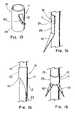
- FIG. 1depicts a perspective view of an illustrative embodiment of the present invention in which the anchoring member comprises a cannula;
- FIG. 2depicts a side view of an illustrative embodiment having fenestrations located about the basal portion to facilitate welding;
- FIG. 3depicts a partially sectioned top view of an illustrative embodiment in which the anchoring element is crimped to the strut;
- FIG. 4depicts a top view of an illustrative embodiment formed from a flat sheet of material
- FIG. 5depicts a perspective view of the embodiment of FIG. 4 that has been formed around and attached to a strut
- FIG. 6depicts a top view of an illustrative embodiment that includes a circumferential locking mechanism
- FIG. 7depicts a side view of an illustrative embodiment comprising a helix configuration
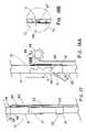
- FIG. 8depicts a perspective view of an illustrative embodiment in which the anchoring element is slidably disposed on the strut;
- FIGS. 10-11Adepict a partially sectioned top view of illustrative embodiments that include structure to restrict rotation of the anchoring element
- FIG. 11Bdepicts a lateral cross-sectional view of the embodiment of FIG. 11A .
- FIG. 17-20depict side and partially sectioned views of slidable anchoring element embodiments which are deployable from non-tissue engaging position into a configuration for penetrating and anchoring into tissue.
- the present inventioncomprises a an intraluminal medical prosthesis 10 that includes an anchoring element 11 having a barb 12 adapted for penetrating tissue to prevent migration of the prosthesis, the anchoring element 11 being formed from a thin layer of material 14 , such as a portion of metal cannula 16 or flat sheet of metal 28 (e.g., stainless steel or nitinol) or other suitable material and configured such that the anchoring element 11 at least partially surrounds or encloses at least one strut 13 of the framework of the prosthesis 10 , whereby the anchoring element 11 is either fixedly or slidably secured to a strut or elongate member 13 of the support structure or frame of the prosthesis.
- a thin layer of material 14such as a portion of metal cannula 16 or flat sheet of metal 28 (e.g., stainless steel or nitinol) or other suitable material and configured such that the anchoring element 11 at least partially surrounds or encloses at least one strut 13 of the framework of the prosthesis
- strut and prosthesis support structureis not particularly critical to the understanding of the invention. It should also be noted that the term ‘cannula’, used herein, is defined to encompass both an anchoring element that is originally formed from a piece of existing cannula as well as an anchoring element that is formed from a flat sheet and is shaped into a closed or partially open tubular configuration.
- FIGS. 1-3depict an embodiment of the present invention in which the anchoring element 11 is laser cut, machined or otherwise formed out of a piece of cannula, such as 304 stainless steel cannula (e.g., 0.006-0.012′′ wall), the preferred size and material of the cannula being determined by the dimensions of the strut to which it is attached and the medical application.
- the anchoring elementincludes an elongate barb 12 extending from the integral basal portion that extends around the strut.
- FIG. 3depicts a cross-sectional view of an anchoring element 11 that has been crimped over a round wire strut 13 with a crimping tool (not shown) that imparts a hexagonal cross-sectional shape to the cannula, a configuration 33 generally regarded as optimal for creating a secure attachment therebetween.
- the barb 12is typically, but not necessarily, plastically deformed or otherwise set into an angled configuration such that it is better able to penetrate and anchor into tissue when the prosthesis expands to contact the inside of a luminal surface.
- FIG. 2depicts the barb 12 set at an angle 23 with respect to the longitudinal axis 26 of the basal portion 25 of the anchoring element 11 (and therefore, the strut 13 ).
- the barb 12includes a bend 22 about the basal portion 20 thereof, it is usually desirable to include fillets 21 at the base 20 to decrease the stress concentrated at that point and reduce the likelihood of fracture.
- the cross-sectional profile of the barb 12is also a factor in producing an optimized anchoring element 11 that is resistant to fracture. It may be desirable to electropolish or otherwise modify its shape, particularly along the basal region, to make it stronger and/or more resistant to fracture.
- FIG. 16is similar to that of FIG. 1 , except that it includes multiple barbs 12 , 51 (two in this particular embodiment) that extend from a single basal portion 25 to provide for additional fixation and/or to improve the likelihood that at least one barb is able to adequately penetrate the adjacent luminal surface.
- FIG. 15depicts a similar embodiment formed from a cannula 16 except that the angle 23 of the barb 12 of the anchoring element 11 that angles away from the basal portion 25 is small or negligible to the point that the barb essentially extends parallel with the strut 13 .
- a barb 12 having an angle of 10° or less (more preferably 5° or less) with respect to the strut to which it is attachedis able to slowly work itself into adjacent tissue and can provide superior anchoring characteristics over typical angled barbs that are configured to more readily penetrate tissue upon contact. This observation applies to both cannula-based and traditional barb designs.
- FIG. 13depicts an embodiment in which the anchoring element 11 also comprises a section of cannula 16 in which the barb 12 is created by cutting or forming the outline 50 thereof completely through the cannula wall that comprises the basal portion 25 , leaving the base 20 uncut, then deforming the barb 12 outward from the base 20 by an amount to ensure penetration of adjacent tissue.
- FIG. 14depicts an embodiment formed from a cannula 16 in which the basal portion 25 is not configured to wrap or extend around a significant portion of the strut, but rather serves merely as a region to locate the weld 24 or otherwise attach the anchoring element 11 to the strut 13 .
- One of the primary advantages of forming an anchor or barb from a thin layer of materialis that the formation or manufacture of the anchoring element can be accomplished by several well-known methods, including laser cutting, EDM, high-pressure jet, chemical etching, machining, grinding, or stamping, thereby producing or attaching barbs more economically and of more consistent quality than is possible with standard barb fabrication techniques that involve soldering wire barbs to the strut.
- the technique of stamping barbs 12would be most appropriate when the source material (thin layer 14 ) comprises a flat metal sheet 28 or otherwise sheet material suitable for the formation of a barb 12 .
- an anchoring element 11that is stamped, laser cut, or otherwise formed from a flat sheet 28 , then reshaped/deformed to at least partially wrap around or enclose the strut 13 to which it is to be attached, as depicted in FIG. 5 .
- the basal portion 25can be configured such that it wraps or extends around more than half of the circumference of the strut while leaving an open area or channel at the back to insert the strut thereinto such that the anchoring element is able to ‘snap’ into place and frictionally engage the strut.
- the anchoring elementcan then be further secured to the strut using one of the aforementioned methods.
- relatively deep filletsprovide stress relief to the barb 12 , and essentially divide the basal portion 25 into a first 29 and a second 30 portion which include a pair of fenestrations 27 or apertures to facilitate the first and second portions 29 , 30 being separately attached to the strut.
- the first and second portions 29 , 30may be optionally configured to touch or overlap to be bonded along the seam created between the lateral edges 52 , 53 thereof as they extend completely around the strut to which they are attached such that the anchoring element 11 generally assumes a tubular configuration.
- tubularencompasses a closed cylinder, a partially open cylinder, or a spiral configuration having a generally cylindrical shape.
- the fillets 21may be smaller in size (depicted as a broken line) such that the base 20 of the barb is more generally located about the distal end 18 of the basal portion 25 (similar to the cannula embodiment of FIG. 1 ) rather than the base 20 of the barb being located more proximally within the basal portion 25 ( FIG. 4 ).
- the depth and configuration of the filletsdetermines the flexibility of the barb and related properties, such as resistance to fatigue, ability of the barb to penetrate and hold, etc.
- An embodiment with shallow filletsis depicted in FIG.
- the barb 12generally extends from the second (distal) end 18 and is located proximate the first lateral edge 52 , which also includes a slot 31 .
- the basal portion 25is configured such that it wraps completely around the strut such that a tab 32 located on the second lateral edge 53 locks into the slot, thereby allowing the anchoring element 11 to enclose the strut 13 .
- the anchoring element 11may be optionally welded, crimped, bonded or otherwise secured to the strut 13 .
- the width of the basal portion 25depends on the diameter of the strut around which it is attached.
- FIG. 7depicts a helix-shaped anchoring element 11 that can be formed from either a cannula or a flat sheet 28 which is then plastically deformed or heat-set into that configuration.
- the helix configuration 34allows it to be wrapped around the strut to which it is attached, especially if made of a highly resilient or shape memory material, rather than requiring it to be inserted over a free end of the strut 13 or support structure and positioned in that manner.
- the spaces 38 between windings 35 of the basal portion 25provide edges between anchoring element 11 and strut 13 to facilitate laser welding.
- the laser welding points 36are preferably located well proximal of the base 20 of the barb 12 , which is attached to the basal winding 37 , to prevent the localized annealing of the metal that can weaken the anchoring ability of the barb. By placing the welds between the windings 35 and away from the distal end 18 of the anchoring element 11 , less heat is transferred to the critical basal area 20 of the barb 12 .
- FIG. 8depicts a cannula-type anchoring element 11 that includes sufficient spacing 49 between the inner surface of strut 13 and the cannula 16 to allow the anchoring element 11 to slide longitudinally along the strut 13 .
- a pair of stops 39 , 40such as solder beads, bands, cured adhesive, etc., are attached or applied to the strut. The stops 39 , 40 limit the longitudinal movement and therefore, define a longitudinal zone 54 of movement for the anchoring element 11 .
- the longitudinal zone 54 of movementhas a length greater than that of the anchoring element so that a specific amount of ‘play’ is selected to allow a barb to move relative to the prosthesis to which it is slidably attached.
- crimps or kinks 43 and/or bends 41 in the strutshown respectively as stop 40 and stop 39 in FIG. 9 , may be used as well as any structure that limits longitudinal movement of the sliding anchoring element 11 .
- FIG. 8crimps or kinks 43 and/or bends 41 in the strut, shown respectively as stop 40 and stop 39 in FIG. 9 .
- the stops 39 , 40are incorporated into the framework pattern as enlarged regions 55 which together establish the longitudinal zone of movement 54 for the anchoring element 11 .
- the apex 42 of the bendserves as a stop 39 to limit movement of the anchoring element 11 .
- FIG. 12comprises an additional useful feature in that the anchoring element 11 can be configured to take advantage of the rectangular or squared profile of the strut to limit the ability of the anchoring element 11 to axially rotate, resulting in sub-optimal or improper orientation of the barb 12 for deployment.
- the corners or edges of the strut 13limit the ability of the anchoring element 11 to rotate and thus keep the barb 12 oriented outward within the desired axial plane with sufficient rigidity to penetrate tissue.
- Thisalso allows the space 49 between the anchoring element 11 and strut 13 to be increased for a ‘looser’ engagement to better facilitate longitudinal movement of the anchoring element 12 , which may be necessary or desirable after the prosthesis 10 has been deployed.
- FIG. 12depicts one potential solution to the problem of axial rotation of a slidably disposed barb; however, struts 13 formed from rounded wire or otherwise having a circular profile require a somewhat different approach.
- FIG. 10depicts an alternative embodiment to limit rotational movement of an anchoring element 11 in which opposite sides of the strut include a flattened area 44 that extends at least along the length of the longitudinal zone 54 that defines the extent of which the anchoring element 11 can travel.
- the anchoring element 11includes at least one flattened region 45 corresponding to the flattened area(s) 44 of the strut 13 which limits the ability of the barb 12 to axially rotate out of the predesignated plane 56 optimum for it to perform its intended function.
- FIGS. 11A-11BAnother alternative embodiment is depicted in FIGS. 11A-11B in which the anchoring element 11 includes a protuberance or tab 47 that is configured to ride or slide within a groove or channel 48 extending longitudinally along the strut 13 .
- the tab 47is integrally formed along the edge 15 of the proximal end 17 of the basal portion 25 of the anchoring element 11 and angled inward to engage the channel 48 that prevents rotational movement of the anchoring element 11 .
- tabs 47may be placed at both the proximal or distal end 17 , 18 or any suitable location along the basal portion 25 (e.g., only at the distal end 18 ).
- One skilled in the artwould recognize the existence of numerous other possible structural adaptations that would solve the problem of limiting axial rotation of the anchoring element 11 that is otherwise allowed to slide longitudinally along the strut 13 .
- FIG. 17depicts one embodiment of a deployable anchoring element 11 which includes a first position or configuration 65 along the strut in which the barb is oriented downward, generally parallel with the strut, rather than outward in its normal tissue-penetration orientation.
- This initial orientation 65advantageously permits the prosthesis 10 to be loaded within a delivery system without having the barbs embedding into the inside surface thereof.
- the first barb position 65can allow the prosthesis to be deployed and repositioned at the implantation site, while maintaining control over when the anchoring procedure is initiated to fix final placement.
- an actuating mechanism 58is used to urge the anchoring element 11 along the strut 13 from the first position to a second position or configuration 66 ( FIG. 18A ) in which the anchoring element contacts a deflecting element 61 , which in the illustrative embodiment comprises a band crimped over or otherwise attached to the strut 13 .
- the deflecting element 61includes a ramped portion 62 , whereby as the barb 12 slides over the ramped portion 62 , it is deflected outward into the desired angle 23 that allows it to more easily engage and embed into adjacent tissue.
- the deflecting element 61functions as the second stop 40 to limit longitudinal movement of the anchoring element 11 .
- the anchoring element 11can be configured with structure ( FIG.
- the illustrative protuberance 63e.g., a tab or lip
- compatible structure 67located along the strut (such as the illustrative recess) that allows the anchoring element 11 to lock in the second position 66 and not slide back proximally toward the first position 65 , thereby causing the barb to perhaps become disengaged from the tissue.
- a channel 70is formed in the inside of the anchoring element 11 cannula in which the protuberance 63 may slide distally until locking into the recess 67 .
- the tether 60can be configured to detach from the urging mechanism 59 or the urging mechanism 59 can be configured to break apart or detach in some other suitable manner.
- FIGS. 19-20depict two alternative embodiments in which the anchoring element 11 is rotated from a first position or configuration 65 in which the barb 12 is oriented away from the implantation surface, into a second position or configuration 66 in which the barb 12 is oriented outward into an anchoring position.
- the spiral guide 57causes the anchoring element 11 to rotate approximately 180° from the first position 65 to the second position 61 .
- the illustrative spiral guide 57comprises a thread or raised ridge formed on the surface of the strut.
- One or more guiding protuberances formed along the inner surface of the basal portion 25 of the anchoring element 11allow the anchoring element 11 to track the spiral ridge 57 which causes the anchoring element 11 and barb 12 to rotate about its axis.
- FIG. 20depicts an embodiment of the present invention in which the strut 13 comprises a twisted configuration 68 (comprising a single twist) that causes the anchoring element 11 , when sliding longitudinally in the distal direction (toward the second position 66 ), to rotate 180° with respect to the strut 13 so that the barb becomes reoriented toward the implantation surface or outer surface of the prosthesis.
- the squared cross-sectional profile of the illustrative strutallows the anchoring element 11 to track the twisted strut path without other guiding structure being necessary.
- a rounded, spiral-shaped strutmay be used, preferably with the guide structure, such as a groove or ridge, included to facilitate proper orientation of the barb 12 .
- the anchoring elementcan be biased using springs or another well-known mechanism, whereby the bias is released using tethers, sleeves, or other mechanisms to allow the barbs to resiliently rotate or reorient to embed into the adjacent tissue.
Landscapes
- Health & Medical Sciences (AREA)
- Engineering & Computer Science (AREA)
- Biomedical Technology (AREA)
- Cardiology (AREA)
- Oral & Maxillofacial Surgery (AREA)
- Transplantation (AREA)
- Heart & Thoracic Surgery (AREA)
- Vascular Medicine (AREA)
- Life Sciences & Earth Sciences (AREA)
- Animal Behavior & Ethology (AREA)
- General Health & Medical Sciences (AREA)
- Public Health (AREA)
- Veterinary Medicine (AREA)
- Gastroenterology & Hepatology (AREA)
- Pulmonology (AREA)
- Prostheses (AREA)
- Media Introduction/Drainage Providing Device (AREA)
- Materials For Medical Uses (AREA)
Abstract
Description
Claims (12)
Priority Applications (2)
| Application Number | Priority Date | Filing Date | Title |
|---|---|---|---|
| US11/044,522US7572289B2 (en) | 2004-01-27 | 2005-01-27 | Anchoring barb for attachment to a medical prosthesis |
| US12/506,012US8029559B2 (en) | 2004-01-27 | 2009-07-20 | Anchoring barb for attachment to a medical prosthesis |
Applications Claiming Priority (2)
| Application Number | Priority Date | Filing Date | Title |
|---|---|---|---|
| US53939104P | 2004-01-27 | 2004-01-27 | |
| US11/044,522US7572289B2 (en) | 2004-01-27 | 2005-01-27 | Anchoring barb for attachment to a medical prosthesis |
Related Child Applications (1)
| Application Number | Title | Priority Date | Filing Date |
|---|---|---|---|
| US12/506,012ContinuationUS8029559B2 (en) | 2004-01-27 | 2009-07-20 | Anchoring barb for attachment to a medical prosthesis |
Publications (2)
| Publication Number | Publication Date |
|---|---|
| US20050240259A1 US20050240259A1 (en) | 2005-10-27 |
| US7572289B2true US7572289B2 (en) | 2009-08-11 |
Family
ID=34826072
Family Applications (2)
| Application Number | Title | Priority Date | Filing Date |
|---|---|---|---|
| US11/044,522Active2026-05-04US7572289B2 (en) | 2004-01-27 | 2005-01-27 | Anchoring barb for attachment to a medical prosthesis |
| US12/506,012Expired - LifetimeUS8029559B2 (en) | 2004-01-27 | 2009-07-20 | Anchoring barb for attachment to a medical prosthesis |
Family Applications After (1)
| Application Number | Title | Priority Date | Filing Date |
|---|---|---|---|
| US12/506,012Expired - LifetimeUS8029559B2 (en) | 2004-01-27 | 2009-07-20 | Anchoring barb for attachment to a medical prosthesis |
Country Status (8)
| Country | Link |
|---|---|
| US (2) | US7572289B2 (en) |
| EP (1) | EP1713416B1 (en) |
| JP (1) | JP4651625B2 (en) |
| AT (1) | ATE455520T1 (en) |
| AU (1) | AU2005209274B2 (en) |
| CA (1) | CA2554574C (en) |
| DE (1) | DE602005019029D1 (en) |
| WO (1) | WO2005072652A1 (en) |
Cited By (55)
| Publication number | Priority date | Publication date | Assignee | Title |
|---|---|---|---|---|
| US20080033534A1 (en)* | 2002-05-16 | 2008-02-07 | Cook Incorporated | Flexible Barb for Anchoring a Prosthesis |
| US20080097518A1 (en)* | 2004-01-22 | 2008-04-24 | Thinnes John H Jr | Vein filter |
| US20080221609A1 (en)* | 2004-01-22 | 2008-09-11 | Mcguckin James F | Vein filter |
| US20090099596A1 (en)* | 2007-05-31 | 2009-04-16 | Rex Medical | Closure device for left atrial appendage |
| US20090198270A1 (en)* | 2008-01-11 | 2009-08-06 | Mcguckin Jr James F | Vein Filter |
| US20090240340A1 (en)* | 2002-12-02 | 2009-09-24 | Gi Dynamics, Inc. | Bariatric sleeve |
| US20090259298A1 (en)* | 2008-04-11 | 2009-10-15 | Kevin Mayberry | Bifurcated graft deployment systems and methods |
| US20100049239A1 (en)* | 2004-01-22 | 2010-02-25 | Rex Medical, Lp | Vein Filter |
| US20100057195A1 (en)* | 2008-08-29 | 2010-03-04 | Roeder Blayne A | Barbed anchors for wire stent |
| US7976562B2 (en) | 2004-01-22 | 2011-07-12 | Rex Medical, L.P. | Method of removing a vein filter |
| US20110208233A1 (en)* | 2004-01-22 | 2011-08-25 | Mcguckin Jr James F | Device for preventing clot migration from left atrial appendage |
| US8034100B2 (en) | 1999-03-11 | 2011-10-11 | Endologix, Inc. | Graft deployment system |
| US8118856B2 (en) | 2009-07-27 | 2012-02-21 | Endologix, Inc. | Stent graft |
| US8167925B2 (en) | 1999-03-11 | 2012-05-01 | Endologix, Inc. | Single puncture bifurcation graft deployment system |
| US20120184986A1 (en)* | 2004-01-22 | 2012-07-19 | Mcguckin Jr James F | Vein Filter |
| EP2481381A1 (en) | 2011-01-28 | 2012-08-01 | Cook Medical Technologies LLC | Barbed anchor |
| US8372109B2 (en) | 2004-08-04 | 2013-02-12 | C. R. Bard, Inc. | Non-entangling vena cava filter |
| US8430903B2 (en) | 2005-08-09 | 2013-04-30 | C. R. Bard, Inc. | Embolus blood clot filter and delivery system |
| US8491646B2 (en) | 2009-07-15 | 2013-07-23 | Endologix, Inc. | Stent graft |
| US8523931B2 (en) | 2007-01-12 | 2013-09-03 | Endologix, Inc. | Dual concentric guidewire and methods of bifurcated graft deployment |
| US8574261B2 (en) | 2005-05-12 | 2013-11-05 | C. R. Bard, Inc. | Removable embolus blood clot filter |
| US8613754B2 (en) | 2005-05-12 | 2013-12-24 | C. R. Bard, Inc. | Tubular filter |
| US20140039602A1 (en)* | 2012-07-31 | 2014-02-06 | Cook Medical Technologies Llc | Barbed anchors for attachment to endoluminal prosthesis |
| US8690906B2 (en) | 1998-09-25 | 2014-04-08 | C.R. Bard, Inc. | Removeable embolus blood clot filter and filter delivery unit |
| US8696700B2 (en) | 2004-01-22 | 2014-04-15 | Rex Medical L.P. | Vein filter |
| US8808350B2 (en) | 2011-03-01 | 2014-08-19 | Endologix, Inc. | Catheter system and methods of using same |
| US8821528B2 (en) | 2001-06-18 | 2014-09-02 | Rex Medical, L.P. | Removable vein filter |
| US8870947B2 (en) | 2011-09-16 | 2014-10-28 | W.L. Gore & Associates, Inc. | Medical device fixation anchors |
| US8920458B2 (en) | 2004-09-27 | 2014-12-30 | Rex Medical, L.P. | Vein filter |
| US8945202B2 (en) | 2009-04-28 | 2015-02-03 | Endologix, Inc. | Fenestrated prosthesis |
| US9131999B2 (en) | 2005-11-18 | 2015-09-15 | C.R. Bard Inc. | Vena cava filter with filament |
| US9204956B2 (en) | 2002-02-20 | 2015-12-08 | C. R. Bard, Inc. | IVC filter with translating hooks |
| US9326842B2 (en) | 2006-06-05 | 2016-05-03 | C. R . Bard, Inc. | Embolus blood clot filter utilizable with a single delivery system or a single retrieval system in one of a femoral or jugular access |
| US9393100B2 (en) | 2010-11-17 | 2016-07-19 | Endologix, Inc. | Devices and methods to treat vascular dissections |
| US9510929B2 (en) | 2004-01-22 | 2016-12-06 | Argon Medical Devices, Inc. | Vein filter |
| US9554806B2 (en) | 2011-09-16 | 2017-01-31 | W. L. Gore & Associates, Inc. | Occlusive devices |
| US9579103B2 (en) | 2009-05-01 | 2017-02-28 | Endologix, Inc. | Percutaneous method and device to treat dissections |
| US9700701B2 (en) | 2008-07-01 | 2017-07-11 | Endologix, Inc. | Catheter system and methods of using same |
| US10076401B2 (en) | 2006-08-29 | 2018-09-18 | Argon Medical Devices, Inc. | Vein filter |
| US10117765B2 (en) | 2011-06-14 | 2018-11-06 | W.L. Gore Associates, Inc | Apposition fiber for use in endoluminal deployment of expandable implants |
| US10188496B2 (en) | 2006-05-02 | 2019-01-29 | C. R. Bard, Inc. | Vena cava filter formed from a sheet |
| US10245166B2 (en) | 2008-02-22 | 2019-04-02 | Endologix, Inc. | Apparatus and method of placement of a graft or graft system |
| US10772717B2 (en) | 2009-05-01 | 2020-09-15 | Endologix, Inc. | Percutaneous method and device to treat dissections |
| US10993803B2 (en) | 2011-04-01 | 2021-05-04 | W. L. Gore & Associates, Inc. | Elastomeric leaflet for prosthetic heart valves |
| US11123174B2 (en) | 2012-03-13 | 2021-09-21 | W. L. Gore & Associates, Inc. | External steerable fiber for use in endoluminal deployment of expandable devices |
| US11129737B2 (en) | 2015-06-30 | 2021-09-28 | Endologix Llc | Locking assembly for coupling guidewire to delivery system |
| US11129622B2 (en) | 2015-05-14 | 2021-09-28 | W. L. Gore & Associates, Inc. | Devices and methods for occlusion of an atrial appendage |
| US11173023B2 (en) | 2017-10-16 | 2021-11-16 | W. L. Gore & Associates, Inc. | Medical devices and anchors therefor |
| US11324615B2 (en) | 2011-11-14 | 2022-05-10 | W. L. Gore & Associates, Inc. | External steerable fiber for use in endoluminal deployment of expandable devices |
| US11382781B2 (en) | 2011-11-14 | 2022-07-12 | W. L. Gore & Associates, Inc. | External steerable fiber for use in endoluminal deployment of expandable devices |
| US11406518B2 (en) | 2010-11-02 | 2022-08-09 | Endologix Llc | Apparatus and method of placement of a graft or graft system |
| US11911258B2 (en) | 2013-06-26 | 2024-02-27 | W. L. Gore & Associates, Inc. | Space filling devices |
| US12115057B2 (en) | 2005-05-12 | 2024-10-15 | C.R. Bard, Inc. | Tubular filter |
| US12310869B2 (en) | 2017-03-08 | 2025-05-27 | W. L. Gore & Associates, Inc. | Steering wire attach for angulation |
| US12409054B2 (en) | 2018-08-31 | 2025-09-09 | W. L. Gore & Associates, Inc. | Pivot delivery system for implantable medical device |
Families Citing this family (94)
| Publication number | Priority date | Publication date | Assignee | Title |
|---|---|---|---|---|
| US6440164B1 (en) | 1999-10-21 | 2002-08-27 | Scimed Life Systems, Inc. | Implantable prosthetic valve |
| GB0020491D0 (en) | 2000-08-18 | 2000-10-11 | Angiomed Ag | Stent with attached element and method of making such a stent |
| US6602286B1 (en) | 2000-10-26 | 2003-08-05 | Ernst Peter Strecker | Implantable valve system |
| US7201771B2 (en) | 2001-12-27 | 2007-04-10 | Arbor Surgical Technologies, Inc. | Bioprosthetic heart valve |
| US6752828B2 (en) | 2002-04-03 | 2004-06-22 | Scimed Life Systems, Inc. | Artificial valve |
| US7959674B2 (en) | 2002-07-16 | 2011-06-14 | Medtronic, Inc. | Suture locking assembly and method of use |
| AU2003285943B2 (en) | 2002-10-24 | 2008-08-21 | Boston Scientific Limited | Venous valve apparatus and method |
| US8551162B2 (en) | 2002-12-20 | 2013-10-08 | Medtronic, Inc. | Biologically implantable prosthesis |
| US6945957B2 (en) | 2002-12-30 | 2005-09-20 | Scimed Life Systems, Inc. | Valve treatment catheter and methods |
| US8021421B2 (en) | 2003-08-22 | 2011-09-20 | Medtronic, Inc. | Prosthesis heart valve fixturing device |
| US7556647B2 (en) | 2003-10-08 | 2009-07-07 | Arbor Surgical Technologies, Inc. | Attachment device and methods of using the same |
| US8128681B2 (en) | 2003-12-19 | 2012-03-06 | Boston Scientific Scimed, Inc. | Venous valve apparatus, system, and method |
| US7854761B2 (en) | 2003-12-19 | 2010-12-21 | Boston Scientific Scimed, Inc. | Methods for venous valve replacement with a catheter |
| US7566343B2 (en) | 2004-09-02 | 2009-07-28 | Boston Scientific Scimed, Inc. | Cardiac valve, system, and method |
| US7854755B2 (en) | 2005-02-01 | 2010-12-21 | Boston Scientific Scimed, Inc. | Vascular catheter, system, and method |
| US20060173490A1 (en) | 2005-02-01 | 2006-08-03 | Boston Scientific Scimed, Inc. | Filter system and method |
| US7670368B2 (en) | 2005-02-07 | 2010-03-02 | Boston Scientific Scimed, Inc. | Venous valve apparatus, system, and method |
| US7780722B2 (en) | 2005-02-07 | 2010-08-24 | Boston Scientific Scimed, Inc. | Venous valve apparatus, system, and method |
| US7867274B2 (en) | 2005-02-23 | 2011-01-11 | Boston Scientific Scimed, Inc. | Valve apparatus, system and method |
| US7513909B2 (en) | 2005-04-08 | 2009-04-07 | Arbor Surgical Technologies, Inc. | Two-piece prosthetic valves with snap-in connection and methods for use |
| US7722666B2 (en) | 2005-04-15 | 2010-05-25 | Boston Scientific Scimed, Inc. | Valve apparatus, system and method |
| JP4912395B2 (en) | 2005-05-24 | 2012-04-11 | エドワーズ ライフサイエンシーズ コーポレイション | Rapid placement prosthetic heart valve |
| US8211169B2 (en) | 2005-05-27 | 2012-07-03 | Medtronic, Inc. | Gasket with collar for prosthetic heart valves and methods for using them |
| US8012198B2 (en) | 2005-06-10 | 2011-09-06 | Boston Scientific Scimed, Inc. | Venous valve, system, and method |
| GB0512319D0 (en) | 2005-06-16 | 2005-07-27 | Angiomed Ag | Catheter device variable pusher |
| GB0512320D0 (en) | 2005-06-16 | 2005-07-27 | Angiomed Ag | Catheter device FLEXX tube |
| US20070027533A1 (en)* | 2005-07-28 | 2007-02-01 | Medtronic Vascular, Inc. | Cardiac valve annulus restraining device |
| US7569071B2 (en) | 2005-09-21 | 2009-08-04 | Boston Scientific Scimed, Inc. | Venous valve, system, and method with sinus pocket |
| US7799038B2 (en) | 2006-01-20 | 2010-09-21 | Boston Scientific Scimed, Inc. | Translumenal apparatus, system, and method |
| US7967857B2 (en) | 2006-01-27 | 2011-06-28 | Medtronic, Inc. | Gasket with spring collar for prosthetic heart valves and methods for making and using them |
| WO2007099448A2 (en)* | 2006-03-03 | 2007-09-07 | Vayro Ltd. | A fastening device |
| JP2009535128A (en) | 2006-04-29 | 2009-10-01 | アーバー・サージカル・テクノロジーズ・インコーポレイテッド | Multi-part prosthetic heart valve assembly and apparatus and method for delivering the same |
| GB0609841D0 (en) | 2006-05-17 | 2006-06-28 | Angiomed Ag | Bend-capable tubular prosthesis |
| GB0609911D0 (en) | 2006-05-18 | 2006-06-28 | Angiomed Ag | Bend-capable stent prosthesis |
| GB0613670D0 (en)* | 2006-07-10 | 2006-08-16 | Angiomed Ag | Tubular metal prosthesis and method of making it |
| US8298281B2 (en)* | 2006-07-18 | 2012-10-30 | Cordis Corporation | Twisted anchoring barb for stent of abdominal aortic aneurysm (AAA) device |
| GB0616729D0 (en) | 2006-08-23 | 2006-10-04 | Angiomed Ag | Method of welding a component to a shape memory alloy workpiece |
| GB0616999D0 (en) | 2006-08-29 | 2006-10-04 | Angiomed Ag | Annular mesh |
| EP2063824B1 (en) | 2006-09-07 | 2020-10-28 | Angiomed GmbH & Co. Medizintechnik KG | Helical implant having different ends |
| GB0622465D0 (en) | 2006-11-10 | 2006-12-20 | Angiomed Ag | Stent |
| GB0624419D0 (en) | 2006-12-06 | 2007-01-17 | Angiomed Ag | Stenting ring with marker |
| WO2008091493A1 (en) | 2007-01-08 | 2008-07-31 | California Institute Of Technology | In-situ formation of a valve |
| US7967853B2 (en) | 2007-02-05 | 2011-06-28 | Boston Scientific Scimed, Inc. | Percutaneous valve, system and method |
| GB0703379D0 (en) | 2007-02-21 | 2007-03-28 | Angiomed Ag | Stent with radiopaque marker |
| US8070802B2 (en)* | 2007-02-23 | 2011-12-06 | The Trustees Of The University Of Pennsylvania | Mitral valve system |
| GB0706499D0 (en) | 2007-04-03 | 2007-05-09 | Angiomed Ag | Bendable stent |
| US8828079B2 (en) | 2007-07-26 | 2014-09-09 | Boston Scientific Scimed, Inc. | Circulatory valve, system and method |
| US9237959B2 (en)* | 2007-08-17 | 2016-01-19 | Cook Medical Technologies Llc | Stent and barb |
| GB0717481D0 (en) | 2007-09-07 | 2007-10-17 | Angiomed Ag | Self-expansible stent with radiopaque markers |
| US8123876B2 (en)* | 2007-12-13 | 2012-02-28 | Cook Medical Technologies Llc | Method for bonding components of medical devices |
| US7892276B2 (en) | 2007-12-21 | 2011-02-22 | Boston Scientific Scimed, Inc. | Valve with delayed leaflet deployment |
| EP2370138B1 (en) | 2008-11-25 | 2020-12-30 | Edwards Lifesciences Corporation | Apparatus for in situ expansion of prosthetic device |
| GB0822106D0 (en) | 2008-12-03 | 2009-01-07 | Angiomed Ag | Retractable catheter |
| EP2358300B1 (en)* | 2008-12-17 | 2016-02-17 | Cook Medical Technologies LLC | Barb for anchoring an implantable medical device within a body vessel |
| US8308798B2 (en) | 2008-12-19 | 2012-11-13 | Edwards Lifesciences Corporation | Quick-connect prosthetic heart valve and methods |
| US8876883B2 (en)* | 2009-04-24 | 2014-11-04 | Medtronic Vascular, Inc. | Self-flaring active fixation element for a stent graft |
| WO2010126889A1 (en)* | 2009-04-27 | 2010-11-04 | Med Institute, Inc. | Stent with protected barbs |
| US8348998B2 (en) | 2009-06-26 | 2013-01-08 | Edwards Lifesciences Corporation | Unitary quick connect prosthetic heart valve and deployment system and methods |
| GB2472602B (en)* | 2009-08-11 | 2011-12-14 | Cook Medical Technologies Llc | Medical device and method of manufacturing same |
| US8568308B2 (en)* | 2009-08-14 | 2013-10-29 | Alan M. Reznik | Customizable, self holding, space retracting arthroscopic/endoscopic cannula system |
| US8834553B2 (en) | 2009-09-11 | 2014-09-16 | Gi Dynamics, Inc. | Anchors with biodegradable constraints |
| AU2010292118B9 (en) | 2009-09-11 | 2014-01-09 | Gi Dynamics, Inc. | Anchors with open heads |
| US8986374B2 (en) | 2010-05-10 | 2015-03-24 | Edwards Lifesciences Corporation | Prosthetic heart valve |
| US8641757B2 (en) | 2010-09-10 | 2014-02-04 | Edwards Lifesciences Corporation | Systems for rapidly deploying surgical heart valves |
| US9125741B2 (en) | 2010-09-10 | 2015-09-08 | Edwards Lifesciences Corporation | Systems and methods for ensuring safe and rapid deployment of prosthetic heart valves |
| US9370418B2 (en) | 2010-09-10 | 2016-06-21 | Edwards Lifesciences Corporation | Rapidly deployable surgical heart valves |
| US8845720B2 (en) | 2010-09-27 | 2014-09-30 | Edwards Lifesciences Corporation | Prosthetic heart valve frame with flexible commissures |
| US9668859B2 (en) | 2011-08-05 | 2017-06-06 | California Institute Of Technology | Percutaneous heart valve delivery systems |
| AU2012355433B2 (en)* | 2011-12-19 | 2016-10-20 | Rotation Medical, Inc. | Apparatus and method for forming pilot holes in bone and delivering fasteners therein for retaining an implant |
| US9078747B2 (en) | 2011-12-21 | 2015-07-14 | Edwards Lifesciences Corporation | Anchoring device for replacing or repairing a heart valve |
| WO2014144247A1 (en) | 2013-03-15 | 2014-09-18 | Arash Kheradvar | Handle mechanism and functionality for repositioning and retrieval of transcatheter heart valves |
| US9468527B2 (en) | 2013-06-12 | 2016-10-18 | Edwards Lifesciences Corporation | Cardiac implant with integrated suture fasteners |
| US9919137B2 (en) | 2013-08-28 | 2018-03-20 | Edwards Lifesciences Corporation | Integrated balloon catheter inflation system |
| JP6178012B2 (en)* | 2014-04-04 | 2017-08-09 | ジャイラス エーシーエムアイ インク | Ureteral stent with anti-migration features |
| US9585752B2 (en) | 2014-04-30 | 2017-03-07 | Edwards Lifesciences Corporation | Holder and deployment system for surgical heart valves |
| JP5986145B2 (en)* | 2014-07-02 | 2016-09-06 | レノボ・シンガポール・プライベート・リミテッド | Portable devices, cable assemblies and USB systems |
| WO2016022797A1 (en) | 2014-08-06 | 2016-02-11 | Edwards Lifesciences Corporation | Multi-lumen cannulae |
| US10231736B2 (en) | 2015-06-11 | 2019-03-19 | The Regents Of The University Of California | System and method for soft tissue gripping |
| CA2989437C (en) | 2015-07-02 | 2023-08-08 | Edwards Lifesciences Corporation | Hybrid heart valves adapted for post-implant expansion |
| CN107920894B (en) | 2015-07-02 | 2020-04-28 | 爱德华兹生命科学公司 | Integrated hybrid heart valve |
| CN108135592B (en) | 2015-09-02 | 2021-05-14 | 爱德华兹生命科学公司 | Spacer for securing a transcatheter valve to a bioprosthetic cardiac structure |
| US10456245B2 (en) | 2016-05-16 | 2019-10-29 | Edwards Lifesciences Corporation | System and method for applying material to a stent |
| GB201611910D0 (en)* | 2016-07-08 | 2016-08-24 | Valtech Cardio Ltd | Adjustable annuloplasty device with alternating peaks and troughs |
| USD846122S1 (en) | 2016-12-16 | 2019-04-16 | Edwards Lifesciences Corporation | Heart valve sizer |
| US10548731B2 (en) | 2017-02-10 | 2020-02-04 | Boston Scientific Scimed, Inc. | Implantable device and delivery system for reshaping a heart valve annulus |
| WO2018230435A1 (en)* | 2017-06-13 | 2018-12-20 | 株式会社カネカ | Indwelling tube in living body |
| WO2018230434A1 (en)* | 2017-06-13 | 2018-12-20 | 株式会社カネカ | In vivo indwelling tube and method for producing same |
| EP3743016B1 (en) | 2018-01-23 | 2024-10-02 | Edwards Lifesciences Corporation | Prosthetic valve holders, systems, and methods |
| US11331103B2 (en) | 2018-03-29 | 2022-05-17 | Boston Scientific Scimed, Inc. | Occlusive medical device with fixation members |
| EP3820412B1 (en) | 2018-07-11 | 2024-02-14 | Boston Scientific Scimed, Inc. | Motorized telescoping medical device delivery system with mechanical bailout feature |
| USD908874S1 (en) | 2018-07-11 | 2021-01-26 | Edwards Lifesciences Corporation | Collapsible heart valve sizer |
| US11497632B2 (en) | 2018-07-30 | 2022-11-15 | Cook Medical Technologies Llc | Spring barb for medical device |
| CN114145802B (en)* | 2021-12-06 | 2023-07-14 | 东南大学泰州生物医药与医疗器械研究院 | Left auricle plugging device forming tool and manufacturing process |
| CN115024782B (en)* | 2022-05-05 | 2025-02-28 | 上海形状记忆合金材料有限公司 | Hook and blocking device |
Citations (20)
| Publication number | Priority date | Publication date | Assignee | Title |
|---|---|---|---|---|
| US5375612A (en)* | 1992-04-07 | 1994-12-27 | B. Braun Celsa | Possibly absorbable blood filter |
| US5489295A (en) | 1991-04-11 | 1996-02-06 | Endovascular Technologies, Inc. | Endovascular graft having bifurcation and apparatus and method for deploying the same |
| US5693084A (en) | 1991-10-25 | 1997-12-02 | Cook Incorporated | Expandable transluminal graft prosthesis for repair of aneurysm |
| US5720776A (en) | 1991-10-25 | 1998-02-24 | Cook Incorporated | Barb and expandable transluminal graft prosthesis for repair of aneurysm |
| US5800526A (en) | 1995-03-17 | 1998-09-01 | Endotex Interventional Systems, Inc. | Multi-anchor stent |
| US5863164A (en) | 1998-01-23 | 1999-01-26 | Sigma Tool & Machine | Tee-nut with radiussed barrel end |
| US5961546A (en) | 1993-04-22 | 1999-10-05 | C.R. Bard, Inc. | Method and apparatus for recapture of hooked endoprosthesis |
| WO2000035352A1 (en) | 1998-12-16 | 2000-06-22 | Scimed Life Systems, Inc. | Implantable device anchors |
| US6113612A (en) | 1998-11-06 | 2000-09-05 | St. Jude Medical Cardiovascular Group, Inc. | Medical anastomosis apparatus |
| US6200336B1 (en) | 1998-06-02 | 2001-03-13 | Cook Incorporated | Multiple-sided intraluminal medical device |
| US6221102B1 (en) | 1983-12-09 | 2001-04-24 | Endovascular Technologies, Inc. | Intraluminal grafting system |
| WO2001076509A1 (en) | 2000-04-11 | 2001-10-18 | Endovascular Technologies, Inc. | Hook for attaching to a corporeal lumen and method of manufacturing |
| US6506190B1 (en) | 1998-05-21 | 2003-01-14 | Christopher J. Walshe | Tissue anchor system |
| US6517574B1 (en) | 2000-04-27 | 2003-02-11 | Endovascular Technologies, Inc. | System and method for endovascular aneurysm repair in conjunction with vascular stabilization |
| US20030120331A1 (en)* | 2001-12-20 | 2003-06-26 | Trivascular, Inc. | Advanced endovascular graft |
| US20030236570A1 (en)* | 2002-05-16 | 2003-12-25 | Cook Incorporated | Flexible barb for anchoring a prosthesis |
| US6676698B2 (en) | 2000-06-26 | 2004-01-13 | Rex Medicol, L.P. | Vascular device with valve for approximating vessel wall |
| US20040117004A1 (en) | 2002-05-16 | 2004-06-17 | Osborne Thomas A. | Stent and method of forming a stent with integral barbs |
| US6849087B1 (en) | 1999-10-06 | 2005-02-01 | Timothy A. M. Chuter | Device and method for staged implantation of a graft for vascular repair |
| US20050038497A1 (en)* | 2003-08-11 | 2005-02-17 | Scimed Life Systems, Inc. | Deformation medical device without material deformation |
- 2005
- 2005-01-27DEDE602005019029Tpatent/DE602005019029D1/ennot_activeExpired - Lifetime
- 2005-01-27ATAT05706090Tpatent/ATE455520T1/ennot_activeIP Right Cessation
- 2005-01-27USUS11/044,522patent/US7572289B2/enactiveActive
- 2005-01-27WOPCT/US2005/002360patent/WO2005072652A1/enactiveApplication Filing
- 2005-01-27EPEP05706090Apatent/EP1713416B1/ennot_activeExpired - Lifetime
- 2005-01-27JPJP2006551411Apatent/JP4651625B2/ennot_activeExpired - Fee Related
- 2005-01-27AUAU2005209274Apatent/AU2005209274B2/ennot_activeCeased
- 2005-01-27CACA2554574Apatent/CA2554574C/ennot_activeExpired - Lifetime
- 2009
- 2009-07-20USUS12/506,012patent/US8029559B2/ennot_activeExpired - Lifetime
Patent Citations (21)
| Publication number | Priority date | Publication date | Assignee | Title |
|---|---|---|---|---|
| US6221102B1 (en) | 1983-12-09 | 2001-04-24 | Endovascular Technologies, Inc. | Intraluminal grafting system |
| US5489295A (en) | 1991-04-11 | 1996-02-06 | Endovascular Technologies, Inc. | Endovascular graft having bifurcation and apparatus and method for deploying the same |
| US5693084A (en) | 1991-10-25 | 1997-12-02 | Cook Incorporated | Expandable transluminal graft prosthesis for repair of aneurysm |
| US5720776A (en) | 1991-10-25 | 1998-02-24 | Cook Incorporated | Barb and expandable transluminal graft prosthesis for repair of aneurysm |
| US5375612A (en)* | 1992-04-07 | 1994-12-27 | B. Braun Celsa | Possibly absorbable blood filter |
| US5961546A (en) | 1993-04-22 | 1999-10-05 | C.R. Bard, Inc. | Method and apparatus for recapture of hooked endoprosthesis |
| US5800526A (en) | 1995-03-17 | 1998-09-01 | Endotex Interventional Systems, Inc. | Multi-anchor stent |
| US5863164A (en) | 1998-01-23 | 1999-01-26 | Sigma Tool & Machine | Tee-nut with radiussed barrel end |
| US6506190B1 (en) | 1998-05-21 | 2003-01-14 | Christopher J. Walshe | Tissue anchor system |
| US6200336B1 (en) | 1998-06-02 | 2001-03-13 | Cook Incorporated | Multiple-sided intraluminal medical device |
| US6113612A (en) | 1998-11-06 | 2000-09-05 | St. Jude Medical Cardiovascular Group, Inc. | Medical anastomosis apparatus |
| WO2000035352A1 (en) | 1998-12-16 | 2000-06-22 | Scimed Life Systems, Inc. | Implantable device anchors |
| US6231581B1 (en)* | 1998-12-16 | 2001-05-15 | Boston Scientific Corporation | Implantable device anchors |
| US6849087B1 (en) | 1999-10-06 | 2005-02-01 | Timothy A. M. Chuter | Device and method for staged implantation of a graft for vascular repair |
| WO2001076509A1 (en) | 2000-04-11 | 2001-10-18 | Endovascular Technologies, Inc. | Hook for attaching to a corporeal lumen and method of manufacturing |
| US6517574B1 (en) | 2000-04-27 | 2003-02-11 | Endovascular Technologies, Inc. | System and method for endovascular aneurysm repair in conjunction with vascular stabilization |
| US6676698B2 (en) | 2000-06-26 | 2004-01-13 | Rex Medicol, L.P. | Vascular device with valve for approximating vessel wall |
| US20030120331A1 (en)* | 2001-12-20 | 2003-06-26 | Trivascular, Inc. | Advanced endovascular graft |
| US20030236570A1 (en)* | 2002-05-16 | 2003-12-25 | Cook Incorporated | Flexible barb for anchoring a prosthesis |
| US20040117004A1 (en) | 2002-05-16 | 2004-06-17 | Osborne Thomas A. | Stent and method of forming a stent with integral barbs |
| US20050038497A1 (en)* | 2003-08-11 | 2005-02-17 | Scimed Life Systems, Inc. | Deformation medical device without material deformation |
Cited By (116)
| Publication number | Priority date | Publication date | Assignee | Title |
|---|---|---|---|---|
| US8690906B2 (en) | 1998-09-25 | 2014-04-08 | C.R. Bard, Inc. | Removeable embolus blood clot filter and filter delivery unit |
| US9351821B2 (en) | 1998-09-25 | 2016-05-31 | C. R. Bard, Inc. | Removable embolus blood clot filter and filter delivery unit |
| US9615909B2 (en) | 1998-09-25 | 2017-04-11 | C.R. Bard, Inc. | Removable embolus blood clot filter and filter delivery unit |
| US8034100B2 (en) | 1999-03-11 | 2011-10-11 | Endologix, Inc. | Graft deployment system |
| US8167925B2 (en) | 1999-03-11 | 2012-05-01 | Endologix, Inc. | Single puncture bifurcation graft deployment system |
| US8821528B2 (en) | 2001-06-18 | 2014-09-02 | Rex Medical, L.P. | Removable vein filter |
| US9204956B2 (en) | 2002-02-20 | 2015-12-08 | C. R. Bard, Inc. | IVC filter with translating hooks |
| US20080033534A1 (en)* | 2002-05-16 | 2008-02-07 | Cook Incorporated | Flexible Barb for Anchoring a Prosthesis |
| US7828839B2 (en)* | 2002-05-16 | 2010-11-09 | Cook Incorporated | Flexible barb for anchoring a prosthesis |
| US20090240340A1 (en)* | 2002-12-02 | 2009-09-24 | Gi Dynamics, Inc. | Bariatric sleeve |
| US8162871B2 (en)* | 2002-12-02 | 2012-04-24 | Gi Dynamics, Inc. | Bariatric sleeve |
| US8137301B2 (en)* | 2002-12-02 | 2012-03-20 | Gi Dynamics, Inc. | Bariatric sleeve |
| US9526604B2 (en)* | 2004-01-22 | 2016-12-27 | Argon Medical Devices, Inc. | Vessel filter |
| US8377093B2 (en) | 2004-01-22 | 2013-02-19 | Rex Medical, L.P. | Method of removing a vein filter |
| US8062326B2 (en) | 2004-01-22 | 2011-11-22 | Rex Medical, L.P. | Vein filter |
| US7976562B2 (en) | 2004-01-22 | 2011-07-12 | Rex Medical, L.P. | Method of removing a vein filter |
| US7704266B2 (en)* | 2004-01-22 | 2010-04-27 | Rex Medical, L.P. | Vein filter |
| US9763766B2 (en) | 2004-01-22 | 2017-09-19 | Argon Medical Devices, Inc. | Vein filter |
| US20100049239A1 (en)* | 2004-01-22 | 2010-02-25 | Rex Medical, Lp | Vein Filter |
| US20120184986A1 (en)* | 2004-01-22 | 2012-07-19 | Mcguckin Jr James F | Vein Filter |
| US8696700B2 (en) | 2004-01-22 | 2014-04-15 | Rex Medical L.P. | Vein filter |
| US9510929B2 (en) | 2004-01-22 | 2016-12-06 | Argon Medical Devices, Inc. | Vein filter |
| US10639139B2 (en) | 2004-01-22 | 2020-05-05 | Argon Medical Devices, Inc. | Vein filter |
| US8366736B2 (en)* | 2004-01-22 | 2013-02-05 | Rex Medical, L.P. | Vein filter |
| US8715313B2 (en) | 2004-01-22 | 2014-05-06 | Rex Medical L.P. | Vessel filter |
| US20110208233A1 (en)* | 2004-01-22 | 2011-08-25 | Mcguckin Jr James F | Device for preventing clot migration from left atrial appendage |
| US9308075B2 (en) | 2004-01-22 | 2016-04-12 | Argon Medical Devices, Inc. | Vessel filter |
| US20080097518A1 (en)* | 2004-01-22 | 2008-04-24 | Thinnes John H Jr | Vein filter |
| US8469990B2 (en) | 2004-01-22 | 2013-06-25 | Rex Medical, L.P. | Vein filter |
| US9168121B2 (en) | 2004-01-22 | 2015-10-27 | Rex Medical, L.P. | Vein filter |
| US8500774B2 (en) | 2004-01-22 | 2013-08-06 | Rex Medical, L.P. | Vein filter |
| US20140066972A1 (en)* | 2004-01-22 | 2014-03-06 | Rex Medical, L.P. | Vessel filter |
| US20080221609A1 (en)* | 2004-01-22 | 2008-09-11 | Mcguckin James F | Vein filter |
| US8591541B2 (en)* | 2004-01-22 | 2013-11-26 | Rex Medical L.P. | Vein filter |
| US8864793B2 (en) | 2004-01-22 | 2014-10-21 | Rex Medical, L.P. | Vein filter |
| US8628556B2 (en) | 2004-08-04 | 2014-01-14 | C. R. Bard, Inc. | Non-entangling vena cava filter |
| US9144484B2 (en) | 2004-08-04 | 2015-09-29 | C. R. Bard, Inc. | Non-entangling vena cava filter |
| US11103339B2 (en) | 2004-08-04 | 2021-08-31 | C. R. Bard, Inc. | Non-entangling vena cava filter |
| US8372109B2 (en) | 2004-08-04 | 2013-02-12 | C. R. Bard, Inc. | Non-entangling vena cava filter |
| US8920458B2 (en) | 2004-09-27 | 2014-12-30 | Rex Medical, L.P. | Vein filter |
| US10813738B2 (en) | 2005-05-12 | 2020-10-27 | C.R. Bard, Inc. | Tubular filter |
| US11730583B2 (en) | 2005-05-12 | 2023-08-22 | C.R. Band. Inc. | Tubular filter |
| US9498318B2 (en) | 2005-05-12 | 2016-11-22 | C.R. Bard, Inc. | Removable embolus blood clot filter |
| US10729527B2 (en) | 2005-05-12 | 2020-08-04 | C.R. Bard, Inc. | Removable embolus blood clot filter |
| US9017367B2 (en) | 2005-05-12 | 2015-04-28 | C. R. Bard, Inc. | Tubular filter |
| US12115057B2 (en) | 2005-05-12 | 2024-10-15 | C.R. Bard, Inc. | Tubular filter |
| US11554006B2 (en) | 2005-05-12 | 2023-01-17 | C. R. Bard Inc. | Removable embolus blood clot filter |
| US8613754B2 (en) | 2005-05-12 | 2013-12-24 | C. R. Bard, Inc. | Tubular filter |
| US8574261B2 (en) | 2005-05-12 | 2013-11-05 | C. R. Bard, Inc. | Removable embolus blood clot filter |
| US11517415B2 (en) | 2005-08-09 | 2022-12-06 | C.R. Bard, Inc. | Embolus blood clot filter and delivery system |
| US10492898B2 (en) | 2005-08-09 | 2019-12-03 | C.R. Bard, Inc. | Embolus blood clot filter and delivery system |
| US9387063B2 (en) | 2005-08-09 | 2016-07-12 | C. R. Bard, Inc. | Embolus blood clot filter and delivery system |
| US8430903B2 (en) | 2005-08-09 | 2013-04-30 | C. R. Bard, Inc. | Embolus blood clot filter and delivery system |
| US12226302B2 (en) | 2005-11-18 | 2025-02-18 | C.R. Bard, Inc. | Vena cava filter with filament |
| US9131999B2 (en) | 2005-11-18 | 2015-09-15 | C.R. Bard Inc. | Vena cava filter with filament |
| US10842608B2 (en) | 2005-11-18 | 2020-11-24 | C.R. Bard, Inc. | Vena cava filter with filament |
| US10188496B2 (en) | 2006-05-02 | 2019-01-29 | C. R. Bard, Inc. | Vena cava filter formed from a sheet |
| US10980626B2 (en) | 2006-05-02 | 2021-04-20 | C. R. Bard, Inc. | Vena cava filter formed from a sheet |
| US11141257B2 (en) | 2006-06-05 | 2021-10-12 | C. R. Bard, Inc. | Embolus blood clot filter utilizable with a single delivery system or a single retrieval system in one of a femoral or jugular access |
| US9326842B2 (en) | 2006-06-05 | 2016-05-03 | C. R . Bard, Inc. | Embolus blood clot filter utilizable with a single delivery system or a single retrieval system in one of a femoral or jugular access |
| US10076401B2 (en) | 2006-08-29 | 2018-09-18 | Argon Medical Devices, Inc. | Vein filter |
| US8523931B2 (en) | 2007-01-12 | 2013-09-03 | Endologix, Inc. | Dual concentric guidewire and methods of bifurcated graft deployment |
| US20090099596A1 (en)* | 2007-05-31 | 2009-04-16 | Rex Medical | Closure device for left atrial appendage |
| US20090198270A1 (en)* | 2008-01-11 | 2009-08-06 | Mcguckin Jr James F | Vein Filter |
| US10245166B2 (en) | 2008-02-22 | 2019-04-02 | Endologix, Inc. | Apparatus and method of placement of a graft or graft system |
| US8764812B2 (en) | 2008-04-11 | 2014-07-01 | Endologix, Inc. | Bifurcated graft deployment systems and methods |
| US8236040B2 (en) | 2008-04-11 | 2012-08-07 | Endologix, Inc. | Bifurcated graft deployment systems and methods |
| US8357192B2 (en) | 2008-04-11 | 2013-01-22 | Endologix, Inc. | Bifurcated graft deployment systems and methods |
| US20090259298A1 (en)* | 2008-04-11 | 2009-10-15 | Kevin Mayberry | Bifurcated graft deployment systems and methods |
| US10512758B2 (en) | 2008-07-01 | 2019-12-24 | Endologix, Inc. | Catheter system and methods of using same |
| US9700701B2 (en) | 2008-07-01 | 2017-07-11 | Endologix, Inc. | Catheter system and methods of using same |
| US8858617B2 (en) | 2008-08-29 | 2014-10-14 | Cook Medical Technologies Llc | Barbed anchors for wire stent |
| US8394139B2 (en) | 2008-08-29 | 2013-03-12 | Cook Medical Technologies Llc | Barbed anchors for wire stent |
| US8696739B2 (en) | 2008-08-29 | 2014-04-15 | Cook Medical Technologies Llc | Barbed anchor |
| US20100057195A1 (en)* | 2008-08-29 | 2010-03-04 | Roeder Blayne A | Barbed anchors for wire stent |
| US8945202B2 (en) | 2009-04-28 | 2015-02-03 | Endologix, Inc. | Fenestrated prosthesis |
| US10603196B2 (en) | 2009-04-28 | 2020-03-31 | Endologix, Inc. | Fenestrated prosthesis |
| US10772717B2 (en) | 2009-05-01 | 2020-09-15 | Endologix, Inc. | Percutaneous method and device to treat dissections |
| US9579103B2 (en) | 2009-05-01 | 2017-02-28 | Endologix, Inc. | Percutaneous method and device to treat dissections |
| US9757262B2 (en) | 2009-07-15 | 2017-09-12 | Endologix, Inc. | Stent graft |
| US8491646B2 (en) | 2009-07-15 | 2013-07-23 | Endologix, Inc. | Stent graft |
| US8821564B2 (en) | 2009-07-27 | 2014-09-02 | Endologix, Inc. | Stent graft |
| US8118856B2 (en) | 2009-07-27 | 2012-02-21 | Endologix, Inc. | Stent graft |
| US9907642B2 (en) | 2009-07-27 | 2018-03-06 | Endologix, Inc. | Stent graft |
| US10874502B2 (en) | 2009-07-27 | 2020-12-29 | Endologix Llc | Stent graft |
| US11406518B2 (en) | 2010-11-02 | 2022-08-09 | Endologix Llc | Apparatus and method of placement of a graft or graft system |
| US9393100B2 (en) | 2010-11-17 | 2016-07-19 | Endologix, Inc. | Devices and methods to treat vascular dissections |
| EP2481381A1 (en) | 2011-01-28 | 2012-08-01 | Cook Medical Technologies LLC | Barbed anchor |
| US12239558B2 (en) | 2011-03-01 | 2025-03-04 | Endologix Llc | Catheter system and methods of using same |
| US10660775B2 (en) | 2011-03-01 | 2020-05-26 | Endologix, Inc. | Catheter system and methods of using same |
| US8808350B2 (en) | 2011-03-01 | 2014-08-19 | Endologix, Inc. | Catheter system and methods of using same |
| US9687374B2 (en) | 2011-03-01 | 2017-06-27 | Endologix, Inc. | Catheter system and methods of using same |
| US9549835B2 (en) | 2011-03-01 | 2017-01-24 | Endologix, Inc. | Catheter system and methods of using same |
| US10993803B2 (en) | 2011-04-01 | 2021-05-04 | W. L. Gore & Associates, Inc. | Elastomeric leaflet for prosthetic heart valves |
| US10117765B2 (en) | 2011-06-14 | 2018-11-06 | W.L. Gore Associates, Inc | Apposition fiber for use in endoluminal deployment of expandable implants |
| US11457925B2 (en) | 2011-09-16 | 2022-10-04 | W. L. Gore & Associates, Inc. | Occlusive devices |
| US8870947B2 (en) | 2011-09-16 | 2014-10-28 | W.L. Gore & Associates, Inc. | Medical device fixation anchors |
| US9333101B2 (en) | 2011-09-16 | 2016-05-10 | W. L. Gore & Associates Inc. | Medical device fixation anchors |
| US9554806B2 (en) | 2011-09-16 | 2017-01-31 | W. L. Gore & Associates, Inc. | Occlusive devices |
| US9597086B2 (en) | 2011-09-16 | 2017-03-21 | W. L. Gore & Associates, Inc. | Occlusive devices |
| US11382781B2 (en) | 2011-11-14 | 2022-07-12 | W. L. Gore & Associates, Inc. | External steerable fiber for use in endoluminal deployment of expandable devices |
| US12257166B2 (en) | 2011-11-14 | 2025-03-25 | W. L. Gore & Associates, Inc. | External steerable fiber for use in endoluminal deployment of expandable devices |
| US11324615B2 (en) | 2011-11-14 | 2022-05-10 | W. L. Gore & Associates, Inc. | External steerable fiber for use in endoluminal deployment of expandable devices |
| US12076227B2 (en) | 2012-03-13 | 2024-09-03 | W. L. Gore & Associates, Inc. | External steerable fiber for use in endoluminal deployment of expandable devices |
| US11123174B2 (en) | 2012-03-13 | 2021-09-21 | W. L. Gore & Associates, Inc. | External steerable fiber for use in endoluminal deployment of expandable devices |
| US9681965B2 (en)* | 2012-07-31 | 2017-06-20 | Cook Medical Technologies Llc | Barbed anchors for attachment to endoluminal prosthesis |
| US20140039602A1 (en)* | 2012-07-31 | 2014-02-06 | Cook Medical Technologies Llc | Barbed anchors for attachment to endoluminal prosthesis |
| US10149775B2 (en) | 2012-07-31 | 2018-12-11 | Cook Medical Technologies Llc | Barbed anchors for attachment to endoluminal prosthesis |
| US11911258B2 (en) | 2013-06-26 | 2024-02-27 | W. L. Gore & Associates, Inc. | Space filling devices |
| US11826052B2 (en) | 2015-05-14 | 2023-11-28 | W. L. Gore & Associates, Inc. | Devices and methods for occlusion of an atrial appendage |
| US11129622B2 (en) | 2015-05-14 | 2021-09-28 | W. L. Gore & Associates, Inc. | Devices and methods for occlusion of an atrial appendage |
| US12186215B2 (en) | 2015-06-30 | 2025-01-07 | Endologix Llc | Locking assembly for coupling guidewire to delivery system |
| US11129737B2 (en) | 2015-06-30 | 2021-09-28 | Endologix Llc | Locking assembly for coupling guidewire to delivery system |
| US12310869B2 (en) | 2017-03-08 | 2025-05-27 | W. L. Gore & Associates, Inc. | Steering wire attach for angulation |
| US11173023B2 (en) | 2017-10-16 | 2021-11-16 | W. L. Gore & Associates, Inc. | Medical devices and anchors therefor |
| US12409054B2 (en) | 2018-08-31 | 2025-09-09 | W. L. Gore & Associates, Inc. | Pivot delivery system for implantable medical device |
Also Published As
| Publication number | Publication date |
|---|---|
| EP1713416B1 (en) | 2010-01-20 |
| WO2005072652A1 (en) | 2005-08-11 |
| US8029559B2 (en) | 2011-10-04 |
| CA2554574A1 (en) | 2005-08-11 |
| AU2005209274B2 (en) | 2010-08-12 |
| AU2005209274A1 (en) | 2005-08-11 |
| ATE455520T1 (en) | 2010-02-15 |
| CA2554574C (en) | 2012-04-24 |
| US20050240259A1 (en) | 2005-10-27 |
| US20100016953A1 (en) | 2010-01-21 |
| JP4651625B2 (en) | 2011-03-16 |
| EP1713416A1 (en) | 2006-10-25 |
| JP2007519486A (en) | 2007-07-19 |
| DE602005019029D1 (en) | 2010-03-11 |
Similar Documents
| Publication | Publication Date | Title |
|---|---|---|
| US7572289B2 (en) | Anchoring barb for attachment to a medical prosthesis | |
| JP4381643B2 (en) | Device for repairing arteries | |
| US11529249B2 (en) | Braided stent with expansion ring and method of delivery | |
| JP4767292B2 (en) | Device for use in closing a septal defect | |
| US7862608B2 (en) | Vascular prosthesis and methods of use | |
| US20080033534A1 (en) | Flexible Barb for Anchoring a Prosthesis | |
| US9017395B2 (en) | Vascular prosthesis and methods of use | |
| US20040117004A1 (en) | Stent and method of forming a stent with integral barbs | |
| US20080221658A1 (en) | Vascular prosthesis and methods of use | |
| JP2006513010A5 (en) | ||
| AU2003265477A1 (en) | Stent and method of forming a stent with integral barbs | |
| WO2013171730A1 (en) | Stent-graft with fixation elements that are radially confined for delivery | |
| EP2842524A1 (en) | Stent with improved flexibility and method for making same | |
| US12070403B2 (en) | Covered stent | |
| JP2024521467A (en) | Support ring, aortic prosthesis and method of formation - Patents.com | |
| EP4129245A1 (en) | Medical device delivery devices, systems, and methods | |
| EP3606445B1 (en) | Delivery system for anchor | |
| CN117693326A (en) | Support ring, aortic prosthesis and method of forming | |
| CN116172641A (en) | Fixation wires that are subjected to forces during deployment of an implantable intravascular treatment device |
Legal Events
| Date | Code | Title | Description |
|---|---|---|---|
| AS | Assignment | Owner name:MED INSTITUTE, INC., INDIANA Free format text:ASSIGNMENT OF ASSIGNORS INTEREST;ASSIGNORS:SISKIN, RICHARD B.;CHOULES, BRIAN D.;NICKLESS, BENJAMIN;AND OTHERS;REEL/FRAME:016737/0365;SIGNING DATES FROM 20050324 TO 20050629 Owner name:COOK INCORPORATED, INDIANA Free format text:ASSIGNMENT OF ASSIGNORS INTEREST;ASSIGNORS:SISKIN, RICHARD B.;CHOULES, BRIAN D.;NICKLESS, BENJAMIN;AND OTHERS;REEL/FRAME:016737/0365;SIGNING DATES FROM 20050324 TO 20050629 | |
| STCF | Information on status: patent grant | Free format text:PATENTED CASE | |
| CC | Certificate of correction | ||
| CC | Certificate of correction | ||
| AS | Assignment | Owner name:COOK MEDICAL TECHNOLOGIES LLC, INDIANA Free format text:ASSIGNMENT OF ASSIGNORS INTEREST;ASSIGNORS:COOK INCORPORATED;WILSON-COOK MEDICAL INCORPORATED;VANCE PRODUCTS INCORPORATED;AND OTHERS;SIGNING DATES FROM 20110315 TO 20110322;REEL/FRAME:026287/0923 | |
| AS | Assignment | Owner name:COOK MEDICAL TECHNOLOGIES LLC, INDIANA Free format text:ASSIGNMENT OF ASSIGNORS INTEREST;ASSIGNOR:MEDICAL ENGINEERING AND DEVELOPMENT INSTITUTE, INC., (D/B/A MED INSTITUTE, INC.);REEL/FRAME:026444/0958 Effective date:20110314 | |
| FPAY | Fee payment | Year of fee payment:4 | |
| SULP | Surcharge for late payment | ||
| FPAY | Fee payment | Year of fee payment:8 | |
| SULP | Surcharge for late payment | Year of fee payment:7 | |
| MAFP | Maintenance fee payment | Free format text:PAYMENT OF MAINTENANCE FEE, 12TH YEAR, LARGE ENTITY (ORIGINAL EVENT CODE: M1553); ENTITY STATUS OF PATENT OWNER: LARGE ENTITY Year of fee payment:12 | |
| AS | Assignment | Owner name:WILMINGTON TRUST, NATIONAL ASSOCIATION, AS COLLATERAL AGENT, DELAWARE Free format text:SECURITY INTEREST;ASSIGNOR:COOK MEDICAL TECHNOLOGIES LLC;REEL/FRAME:066700/0277 Effective date:20240227 |