US7572276B2 - Minimally invasive instruments and methods for inserting implants - Google Patents
Minimally invasive instruments and methods for inserting implantsDownload PDFInfo
- Publication number
- US7572276B2 US7572276B2US10/202,918US20291802AUS7572276B2US 7572276 B2US7572276 B2US 7572276B2US 20291802 AUS20291802 AUS 20291802AUS 7572276 B2US7572276 B2US 7572276B2
- Authority
- US
- United States
- Prior art keywords
- implant
- insertion instrument
- pair
- holder
- implant holder
- Prior art date
- Legal status (The legal status is an assumption and is not a legal conclusion. Google has not performed a legal analysis and makes no representation as to the accuracy of the status listed.)
- Active, expires
Links
- 239000007943implantSubstances0.000titleclaimsabstractdescription339
- 238000000034methodMethods0.000titleabstractdescription11
- 238000003780insertionMethods0.000claimsabstractdescription157
- 230000037431insertionEffects0.000claimsabstractdescription157
- 230000007246mechanismEffects0.000claimsdescription27
- 210000000988bone and boneAnatomy0.000claimsdescription23
- 238000001356surgical procedureMethods0.000abstractdescription5
- 238000012978minimally invasive surgical procedureMethods0.000abstractdescription2
- 230000037361pathwayEffects0.000description23
- 210000001519tissueAnatomy0.000description19
- 210000003811fingerAnatomy0.000description12
- 230000004927fusionEffects0.000description6
- 238000002224dissectionMethods0.000description5
- 208000014674injuryDiseases0.000description3
- 210000003813thumbAnatomy0.000description3
- 230000008733traumaEffects0.000description3
- 210000003484anatomyAnatomy0.000description2
- 238000013459approachMethods0.000description2
- 238000012986modificationMethods0.000description2
- 230000004048modificationEffects0.000description2
- 241000321728Tritogonia verrucosaSpecies0.000description1
- 230000004075alterationEffects0.000description1
- 230000008901benefitEffects0.000description1
- 210000003205muscleAnatomy0.000description1
- 230000008569processEffects0.000description1
- 230000001737promoting effectEffects0.000description1
- 238000011084recoveryMethods0.000description1
- 231100000241scarToxicity0.000description1
- 239000002407tissue scaffoldSubstances0.000description1
- 238000013519translationMethods0.000description1
- 230000000472traumatic effectEffects0.000description1
- 210000005166vasculatureAnatomy0.000description1
- 210000002517zygapophyseal jointAnatomy0.000description1
Images


Classifications
- A—HUMAN NECESSITIES
- A61—MEDICAL OR VETERINARY SCIENCE; HYGIENE
- A61B—DIAGNOSIS; SURGERY; IDENTIFICATION
- A61B17/00—Surgical instruments, devices or methods
- A61B17/56—Surgical instruments or methods for treatment of bones or joints; Devices specially adapted therefor
- A61B17/58—Surgical instruments or methods for treatment of bones or joints; Devices specially adapted therefor for osteosynthesis, e.g. bone plates, screws or setting implements
- A61B17/68—Internal fixation devices, including fasteners and spinal fixators, even if a part thereof projects from the skin
- A61B17/70—Spinal positioners or stabilisers, e.g. stabilisers comprising fluid filler in an implant
- A61B17/7074—Tools specially adapted for spinal fixation operations other than for bone removal or filler handling
- A61B17/7083—Tools for guidance or insertion of tethers, rod-to-anchor connectors, rod-to-rod connectors, or longitudinal elements
- A—HUMAN NECESSITIES
- A61—MEDICAL OR VETERINARY SCIENCE; HYGIENE
- A61B—DIAGNOSIS; SURGERY; IDENTIFICATION
- A61B17/00—Surgical instruments, devices or methods
- A61B17/56—Surgical instruments or methods for treatment of bones or joints; Devices specially adapted therefor
- A61B17/58—Surgical instruments or methods for treatment of bones or joints; Devices specially adapted therefor for osteosynthesis, e.g. bone plates, screws or setting implements
- A61B17/88—Osteosynthesis instruments; Methods or means for implanting or extracting internal or external fixation devices
- A—HUMAN NECESSITIES
- A61—MEDICAL OR VETERINARY SCIENCE; HYGIENE
- A61B—DIAGNOSIS; SURGERY; IDENTIFICATION
- A61B17/00—Surgical instruments, devices or methods
- A61B17/56—Surgical instruments or methods for treatment of bones or joints; Devices specially adapted therefor
- A—HUMAN NECESSITIES
- A61—MEDICAL OR VETERINARY SCIENCE; HYGIENE
- A61B—DIAGNOSIS; SURGERY; IDENTIFICATION
- A61B17/00—Surgical instruments, devices or methods
- A61B17/56—Surgical instruments or methods for treatment of bones or joints; Devices specially adapted therefor
- A61B17/58—Surgical instruments or methods for treatment of bones or joints; Devices specially adapted therefor for osteosynthesis, e.g. bone plates, screws or setting implements
- A61B17/68—Internal fixation devices, including fasteners and spinal fixators, even if a part thereof projects from the skin
- A61B17/80—Cortical plates, i.e. bone plates; Instruments for holding or positioning cortical plates, or for compressing bones attached to cortical plates
- A61B17/808—Instruments for holding or positioning bone plates, or for adjusting screw-to-plate locking mechanisms
- A—HUMAN NECESSITIES
- A61—MEDICAL OR VETERINARY SCIENCE; HYGIENE
- A61B—DIAGNOSIS; SURGERY; IDENTIFICATION
- A61B17/00—Surgical instruments, devices or methods
- A61B17/02—Surgical instruments, devices or methods for holding wounds open, e.g. retractors; Tractors
- A61B17/0218—Surgical instruments, devices or methods for holding wounds open, e.g. retractors; Tractors for minimally invasive surgery
- A—HUMAN NECESSITIES
- A61—MEDICAL OR VETERINARY SCIENCE; HYGIENE
- A61B—DIAGNOSIS; SURGERY; IDENTIFICATION
- A61B17/00—Surgical instruments, devices or methods
- A61B17/56—Surgical instruments or methods for treatment of bones or joints; Devices specially adapted therefor
- A61B17/58—Surgical instruments or methods for treatment of bones or joints; Devices specially adapted therefor for osteosynthesis, e.g. bone plates, screws or setting implements
- A61B17/68—Internal fixation devices, including fasteners and spinal fixators, even if a part thereof projects from the skin
- A61B17/70—Spinal positioners or stabilisers, e.g. stabilisers comprising fluid filler in an implant
- A61B17/7059—Cortical plates
- A—HUMAN NECESSITIES
- A61—MEDICAL OR VETERINARY SCIENCE; HYGIENE
- A61B—DIAGNOSIS; SURGERY; IDENTIFICATION
- A61B17/00—Surgical instruments, devices or methods
- A61B17/56—Surgical instruments or methods for treatment of bones or joints; Devices specially adapted therefor
- A61B17/58—Surgical instruments or methods for treatment of bones or joints; Devices specially adapted therefor for osteosynthesis, e.g. bone plates, screws or setting implements
- A61B17/68—Internal fixation devices, including fasteners and spinal fixators, even if a part thereof projects from the skin
- A61B17/70—Spinal positioners or stabilisers, e.g. stabilisers comprising fluid filler in an implant
- A61B17/7062—Devices acting on, attached to, or simulating the effect of, vertebral processes, vertebral facets or ribs ; Tools for such devices
- A61B17/7065—Devices with changeable shape, e.g. collapsible or having retractable arms to aid implantation; Tools therefor
- A—HUMAN NECESSITIES
- A61—MEDICAL OR VETERINARY SCIENCE; HYGIENE
- A61B—DIAGNOSIS; SURGERY; IDENTIFICATION
- A61B17/00—Surgical instruments, devices or methods
- A61B17/00234—Surgical instruments, devices or methods for minimally invasive surgery
- A61B2017/00238—Type of minimally invasive operation
Definitions
- Surgery for a patientcan be painful and traumatic, particularly in the affected area of the patient's body.
- the dissection and retraction required to access the surgical site in the patientcan cause trauma to the dissected and retracted tissue as well as to the surrounding tissue.
- the tissuemust heal properly for satisfactory patient recovery, and scar tissue can even result when the affected tissue heals.
- Tissue dissection and retractioncan be required to insert an implant in a patient to a surgical site.
- Some proceduresinvolve mounting the implant on an instrument that holds the implant as it is inserted to the surgical site.
- the inventionrelates instruments and methods for inserting one or more implants to a surgical site in a patient in a surgical procedure, including minimally invasive surgical procedures.
- a systemincludes an implant positionable adjacent a surgical space associated with a spinal column of a patient and an insertion instrument.
- the insertion instrumentincludes an articulating implant holder adjacent a distal end thereof releasably engageable to the implant.
- the implantis moveable with the implant holder between a reduced profile orientation relative to the insertion instrument and an increased profile orientation relative to the insertion instrument.
- the implant holderis adapted to release the implant from the implant holder in the increased profile orientation when the implant is unconstrained relative to the surgical space.
- a systemthat includes an implant positionable adjacent a surgical space associated with a spinal column of a patient and an insertion instrument.
- the insertion instrumentincludes an articulating implant holder at a distal end thereof releasably engageable to the implant.
- the implant holderis movably biased to a first position where the implant has a reduced profile orientation relative to the insertion instrument.
- the implant holderis moveable from the biased first position to a second position where the implant has an increased profile relative to the insertion instrument.
- a systemin accordance with another aspect, includes an elongated implant having a first end and a second end and a central axis extending therebetween.
- the systemalso includes a control system, a connector system having a proximal end portion adjacent the control system and a distal end portion.
- An implant holderis positioned adjacent the distal end portion of the connector system and is releasably engageable with the implant between its first and second ends.
- the implant holderis movable between a reduced profile orientation where the central axis of the implant extends generally along a longitudinal axis of the connector system and a desired orientation where the central axis of the implant extends generally transverse to the longitudinal axis of the implant.
- a systemthat includes a bone plate having a receptacle therein and an insertion instrument.
- the insertion instrumentincludes an articulatable implant holder adjacent a distal end thereof releasably engageable in the receptacle of the bone plate.
- the implant holderis movable from a first position where the bone plate has a reduced profile orientation relative to the insertion instrument for insertion of the bone plate to a surgical space in a patient to a second position where the bone plate has an enlarged profile relative to the insertion instrument for engagement of the bone plate at the surgical space.
- a systemincludes an elongated spinal rod and an insertion instrument.
- the insertion instrumentincludes an articulatable implant holder adjacent a distal end thereof releasably clampable about the spinal rod.
- the implant holderis movable from a first position where the spinal rod has a reduced profile orientation relative to the insertion instrument for insertion of the spinal rod to a surgical space in a patient to a second position where the spinal rod has an enlarged profile relative to the insertion instrument for engagement of the spinal rod at the surgical space.
- an insertion instrumentfor positioning an implant at a surgical site in a patient.
- the insertion instrumentincludes a control system, a connector system extending distally from the control system, and an implant holder adjacent a distal end of the connector system.
- a locking systemassociated with the implant holder that is remotely actuatable between an unlocked position where the implant holder is released from the implant to a locked position where the implant holder is engaged with the implant.
- a manipulator system associated with themoves the implant holder between a first position where the implant has a reduced profile orientation for insertion to the surgical site and a second position providing an enlarged profile.
- an insertion instrumentfor positioning an implant at a surgical space in a patient.
- the insertion instrumentincludes a handle assembly and a shaft assembly extending distally from the handle assembly.
- the shaft assemblyincludes a first shaft axially translatable relative to a second shaft.
- An implant holderis positioned adjacent a distal end of one of the first and second shafts.
- the implant holderis releasably engageable with the implant.
- the implant holderhas a reduced profile orientation for insertion of the implant to the surgical site and is movable to an enlarged profile orientation for positioning the implant at the surgical space upon axial translation of the first and second shafts relative to one another.
- a method for positioning a bone plate along a spinal column of a patientincludes accessing the spinal column through a minimally invasive access path through skin and tissue of the patient; securing the bone plate on an insertion instrument with a longitudinal axis of the bone plate extending generally in the direction of the path through the skin and tissue; positioning the bone plate through the path with the insertion instrument to a location adjacent the spinal column; and remotely manipulating the bone plate relative to the insertion instrument to a desired orientation along the spinal column.
- an insertion instrumentfor positioning an implant at a surgical space in a patient.
- the insertion instrumentincludes a handle assembly and a shaft assembly extending distally from said handle assembly.
- An implant holderis positioned adjacent a distal end of the shaft assembly.
- the implant holderis releasably engageable to the implant and is moveable between a reduced profile orientation relative to the shaft assembly and an increased profile orientation relative to the shaft assembly.
- the implant holderis adapted to release the implant when the implant is positioned adjacent to and substantially unconstrained in the surgical space.
- a method for positioning a spinal rod along a spinal column of a patientincludes accessing the spinal column through a minimally invasive access path through skin and tissue of the patient; securing the spinal rod on an insertion instrument with a longitudinal axis of the spinal rod extending generally in the direction of the path through the skin and tissue; positioning the spinal rod through the path with the insertion instrument to a location adjacent the spinal column; and remotely manipulating the spinal rod relative to the insertion instrument to a desired orientation along the spinal column.
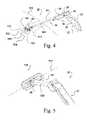
- FIG. 1is a diagrammatic illustration of an implant insertion system.
- FIG. 2is a perspective view showing an insertion instrument with an implant engaged thereto in a reduced profile orientation before insertion of the implant to a surgical space in a patient.
- FIG. 3is an enlarged perspective view of the distal end of the insertion instrument and the implant of FIG. 2 .
- FIG. 4is a perspective view showing the insertion instrument with the implant engaged thereto in an actuated orientation after insertion of the implant to the surgical space in the patient.
- FIG. 5is a perspective view looking at the proximal end of the insertion instrument and the implant with the thumb lever in a locked position.
- FIG. 6is an enlarged perspective view of the distal end portion of the insertion instrument the thumb lever in a locked position.
- FIG. 7is a perspective view looking at the proximal end of the insertion instrument and implant with the thumb lever in an unlocked position.
- FIG. 8is a perspective view of the distal end portion of the insertion instrument of FIG. 2 in an unlocked position and uncoupled from the implant of FIG. 2 .
- FIG. 9is a view of the bottom of the implant with the distal end portion of the insertion instrument positioned in a receptacle of the implant and unengaged thereto.
- FIG. 10is a view of the bottom of the implant with the distal end portion of the insertion instrument positioned therein and engaged thereto.
- FIG. 11is a perspective view showing another embodiment insertion instrument with an implant engaged thereto in a reduced profile orientation before insertion of the implant to a surgical space in a patient.
- FIG. 12is an enlarged perspective view of the distal end of the insertion instrument and the implant of FIG. 11 .
- FIG. 13is a perspective view showing the insertion instrument of FIG. 11 with the implant engaged thereto in an actuated orientation after insertion of the implant to the surgical space in the patient.
- FIG. 14is an enlarged perspective view of the distal end of the insertion instrument and the implant of FIG. 13 .
- FIG. 15is a perspective view of the distal end portion of the implant insertion instrument of FIG. 11 with the clamping members and articulating member removed therefrom.
- FIG. 16is a perspective view of the distal end portion of the insertion instrument of FIG. 11 with the clamping members removed therefrom and the cam member in the unlocked position.
- FIG. 17is a perspective view of the distal end portion of the insertion instrument of FIG. 11 with the clamping members removed therefrom and the cam member in the locked position.
- FIG. 18is a perspective view of the distal end portion of the insertion instrument of FIG. 11 with the clamping members in a disengaged position.
- FIG. 19is a perspective view of the distal end portion of the insertion instrument of FIG. 11 with the clamping members in an engaged position.
- an implant insertion instrument 10 for remotely holding, manipulating and releasing a surgical implant 11include an articulating implant holder 12 spaced apart along a connector system 13 from a control system 14 .
- Control system 14remotely allows direct positioning of implant holder 12 within a surgical space 15 , such as within a body cavity accessed in an open or minimally-invasive fashion.
- insertion instrument 10includes a manipulator system 16 for adjusting an orientation of implant holder 12 , and hence implant 11 , relative to the insertion instrument.
- insertion instrument 10may include a lock system 17 for releasably securing implant 11 relative to the insertion instrument.
- Manipulator system 16 and lock system 17may be remotely positioned relative to implant holder 12 , and may form a portion of control system 14 .
- insertion instrument 10secures implant 11 on implant holder 12 , such as through adjusting lock system 17 into a locked state, and control system 14 directs insertion of the implant into surgical space 15 .
- manipulator system 16positions implant holder 12 and implant 11 in a first orientation, which may be a rigidly fixed position.
- manipulator system 16may reposition implant holder 12 and implant 11 into at least a second orientation, which may be a rigidly fixed position, that facilitates fixation of the implant within the surgical space.
- Insertion instrument 10is disconnected from implant 11 by adjusting lock system 17 into an unlocked state, and the insertion instrument may be removed from surgical space 15 .
- Surgical implant 11may include any implantable device. Suitable examples of surgical implant 11 include a plate, a rod, a bone screw, a multi-axial bone screw, a fusion member, an artificial disc implant, an articulation member, an anchor, a staple, an interbody fusion device, and a tissue scaffold.
- Implant holder 12includes a structure configured to hold implant 11 .
- Implant holder 12may include expanding mechanisms, contracting mechanism, grasping mechanisms, screw mechanisms, wedge structures, dove-tail structures, and ball-detent mechanisms, for example.
- Implant holder 12may be integral with or separate from connector system 13 and also locking system 17 .
- Connector system 13includes a member connectable between manipulator system 16 and implant holder 12 . Additionally, connector system 13 may be rigid, flexible or a combination of both. Connector system 13 may include tubular elements, rod-like elements, linkages, elastically-deformable members, and articulating connectors, for example.
- Control system 14includes a member, such as a handle, for controlling the depth, angular orientation and rotational orientation of implant holder 12 .
- Other suitable examples of control system 14include t-bars, pistol-grips, hooks, circular finger controls, co-axial shafts, and side-by-side shafts.
- Manipulator system 16includes any device or mechanism capable of adjusting the position or orientation of implant holder 12 and/or implant 11 relative to insertion instrument 10 .
- Manipulator system 16may include linkage systems, wire systems, gear systems, flexible adjustment systems, etc.
- Manipulator system 16may include linear and/or rotationally moving elements.
- Manipulation system 16may rigidly fix the position of implant holder 12 relative to insertion instrument 10 throughout and/or only at predetermined portions along a range of orientations relative to insertion instrument 10 .
- Lock system 17includes any device or mechanism capable of releasably securing implant 11 to insertion instrument 10 . Suitable examples of lock system 17 include force-fit or wedge-type locking mechanisms, pivoting lock mechanisms, rotating lock mechanisms, geared lock mechanisms, etc. Lock system 17 may rigidly secure implant 11 to implant holder 12 throughout and/or only at predetermined portions along a range of orientations of the implant holder relative to insertion instrument 10 .
- Insertion instrument 20will be described with specific reference to an implant 100 in the form of a plate attachable to anchors 120 , 121 engaged to vertebrae 552 and 554 , respectively, of the spinal column of the patient.
- Insertion instrument 20has a control system that includes a proximal handle assembly 22 , and connector and manipulator systems that include a shaft assembly 24 extending distally from handle assembly 22 .
- Insertion instrument 20further includes an implant holder 26 at the distal end of shaft assembly 24 .
- Implant 100is releasably mountable to implant holder 26 .
- implant 100may be rigidly mounted on insertion instrument 20 in a first position having a low profile orientation for insertion of implant 100 to a surgical space in a patient through pathway 130 .
- longitudinal axis 510 of implant 100may be at any angle from 0 degrees to less than 90 degrees relative to longitudinal axis 500 of shaft assembly 24 .
- axis 510may be obliquely oriented to and in the general direction of longitudinal axis 500 of shaft assembly 24 .
- implant 100has a curved central axis 510 , although implants with linear central axes are also contemplated.
- central axis 510 of implant 100could be coaxial with or parallel to longitudinal axis 500 in the reduced profile orientation.
- This reduced profile orientationminimizes the footprint of implant 100 relative to insertion instrument 20 and transverse to its insertion path as implant 100 is inserted through pathway 130 to the surgical space. After insertion through pathway 130 , implant 100 is moved from its reduced profile insertion orientation to a desired orientation relative to anchors 120 , 121 for engagement of implant 100 thereto.
- handle assembly 22is manipulated by the surgeon to actuate implant holder 26 through shaft assembly 24 to move implant 100 to a second position or orientation with respect to insertion instrument 20 , and also with respect to anchors 120 , 121 .
- Implant 100may be rigidly fixed to implant holder 26 throughout the movement from the first position to the second position.
- longitudinal axis 510 of implant 100extends more transversely to longitudinal axis 500 of shaft assembly 24 than when in the reduced profile orientation. It is contemplated that the actuated implant 100 is placed in the desired orientation for engagement of implant 100 with anchors 120 , 121 .
- the footprint of implant 100 in the implant insertion direction through pathway 130can be greater than the opening of pathway 130 at least adjacent skin level 550 .
- the amount of tissue dissection and retraction required to accommodate insertion of implant 100 to the surgical spaceis minimized.
- Handle assembly 22may include a remote lock mechanism for remotely securing and releasing implant 100 relative to instrument 20 . Further instruments and implants such as set screws, nuts, sutures, anchors or other fastening elements can be inserted through pathway 130 to secure implant 100 at the surgical space.
- the surgical spaceis associated with the spine of the patient, and implant 100 is a plate attachable to anchors 120 and 121 engaged to vertebrae 552 and 554 , respectively, on each either side of disc space 556 .
- Pathway 130is a retractor sleeve that provides a protected working channel through skin 550 to the surgical space.
- the illustrated retractor sleeveis inserted in a cylindrical configuration through skin 550 and thereafter expandable to a frusto-conically shaped configuration to provide access to each of the anchors 120 , 121 at the distal end thereof through the working channel.
- the opening size of pathway 130 at skin 550 and to the surgical spaceis minimized to reduce the incision size and trauma to the surrounding tissue.
- Pathway 130can also be formed by non-expandable retractor sleeves or guide sleeve, or by a micro-incision or open incision without a retractor sleeve, or by tissue retractors that do not form a sleeve. It is also contemplated that the tissue through pathway 130 can be sequentially dilated to form the desired pathway size while minimizing trauma to the adjacent tissue. Endoscopic, microscopic or other viewing instruments and techniques are contemplated for viewing the surgical space.
- implant 100is a bone plate.
- implantssuch as a rod, strut, linking member, bone fusion member, articulating member, or other implant in which it is desirable to minimize its profile for insertion through a pathway and thereafter alter its orientation after insertion through the pathway.
- Anchors 120 , 121can be bone screws or bolts with proximal ends adapted to receive implant 100 thereover or therein.
- Anchors 120 , 121can also be bone screws that are multi-axial or uni-axial in form.
- Anchors 120 , 121can also be, for example, in the form of hooks, staples, spikes, clamps, interbody fusion devices, interbody implants, intravertebral fusion device, or other intravertebral or intervertebral implant.
- the proximal ends of anchors 120 , 121 to which implant 100 is engagedcan be a threaded or unthreaded stem, U-shaped yoke or other receptacle or bearing surface configured for engagement with an implant 100 . It is further contemplated that implant 100 can be placed against or adjacent to the bone or tissue to which it is to be engaged, and then engaged thereto with anchors positioned after implant placement.
- One specific applicationcontemplates positioning the implant at a surgical space on or near the spine. Any one of a number of approaches to the spine are contemplated, including anterior, posterior, lateral, poster-lateral, antero-lateral approaches, for example.
- the insertion instrumentcan be employed in endoscopic, laparoscopic, thorascopic or other minimally invasive or open procedures.
- the implantcan be attached to bony portions of the spine, including, for example, the vertebral bodies, vertebral endplates, pedicles, facet joints, or the various processes of the spine. Applications in areas other than spinal surgery are also contemplated.
- handle assembly 22includes distal handle portion 30 pivotally coupled via a pin 38 to an extension 34 of a proximal handle portion 32 .
- Shaft assembly 24includes an outer shaft 40 extending along axis 500 between handle assembly 22 and implant holder 26 .
- Distal handle portion 30is engaged to an outer shaft extension 42 ( FIG. 2 .)
- Outer shaft extension 42extends proximally from outer shaft 40 through extension 34 , where it is coupled with distal handle portion 30 with pin 36 .
- An intermediate shaft 46is coupled to and extends proximally from extension 34 of proximal handle portion 32 .
- Distal handle portion 30 and proximal handle portion 32can be biased via a spring or the like to the position shown in FIG.
- a lock system associated with insertion instrument 20includes a cam member 48 extending through intermediate shaft 44 , and a lever 50 at a proximal end of intermediate shaft 44 .
- Lever 50is manipulated by the surgeon to move cam member 48 between an unlocked position, as shown in FIGS. 7 , 8 and 9 , and a locked position, as shown in FIGS. 2 , 4 , 5 , 6 and 10 .
- cam member 48is engageable with engagement members that couple the implant to implant holder 26 of insertion instrument 20 .
- a linkage mechanism 52is coupled between the distal end of outer shaft 40 and implant holder 26 .
- Linkage mechanism 52includes a link 54 pivotally coupled to a bracket 56 extending laterally from the distal end of outer shaft 40 .
- the opposite end of link 54is pivotally coupled to a bracket 58 of implant holder 26 .
- Implant holder 26further includes an articulating member 60 pivotally mounted to a mounting portion 47 at the distal end of intermediate shaft 46 .
- Cam member 48extends through intermediate shaft 46 , including mounting portion 47 .
- a pair of fingers 61 , 62extend distally from articulating member 60 , forming a distal lip 63 therewith. Fingers 61 , 62 each include a hole 64 (only one shown) therethrough.
- a pair of engagement members 66 , 67are movably captured in mounting portion 47 of intermediate shaft 46 .
- engagement members 66 , 67can move into mounting portion 47 and recess below the outer surfaces of fingers 61 , 62 , as shown in FIGS. 7-9 .
- cam member 48contacts engagement members 66 , 67 and forces each outwardly relative to mounting portion 47 and through the aligned holes 64 of fingers 61 , 62 , as shown in FIGS. 4 , 5 , 6 and 10 .
- Engagement members 66 , 67may have a spherically shaped surface extending from fingers 61 , 62 to allow the implant to force the engagement members into the recessed position to facilitate mounting, dismounting and locking of the implant.
- Engagement members 66 , 67can be provided with an enlarged shoulder (not shown) within mounting portion 47 that abuts mounting portion 47 when engagement members 66 , 67 extend from fingers 61 , 62 to retain engagement members 66 , 67 therein.
- Implant 100may include a receptacle 102 defined by a pair of upper rails 104 , 105 and a pair of lower rails 106 , 107 . Slidably positioned between rails 104 , 105 and rails 106 , 107 are slide washers 108 , 109 . Washers 108 , 109 each have a hole therethrough sized to receive an anchor to couple implant 100 to a bony segment, such as adjacent vertebrae 552 and 554 .
- Washers 108 , 109can be slidably adjusted along the upper and lower rails and positioned at the desired location in the plate based on the anchor spacing. It is further contemplated that implant 100 can include more than two washers 108 , 109 . It should be understood that implant 100 can be any type of plate or implant which has a receptacle sized to receive implant holder 26 . Other embodiments contemplate that implant 100 does not include a receptacle, but rather the insertion instrument is coupled to the implant via other means. For example, the implant holder could be clamped around the implant or a portion of the implant, or the implant holder could be fastened to the implant.
- implant 100is mounted to insertion instrument 20 by inserting holding portion 26 into receptacle 102 of the implant.
- insertion instrumentTo mount implant 100 on holding portion 26 , it may be desirable for insertion instrument to be placed in its actuated condition.
- distal handle portion 30can be moved toward proximal handle portion 32 to translate outer shaft 40 proximally along intermediate shaft 46 .
- linkage mechanism 52to pivot so that link 54 extends along intermediate shaft 46 , pulling the side of articulating member 60 coupled to link 52 proximally as well.
- lever 50is moved to its unlocked position ( FIG.
- lever 50is moved to its locked position, thus rotating cam member 48 and pushing engagement members 66 , 67 out respective ones of the holes 64 , as shown in FIG. 10 .
- the outwardly biased engagement members 66 , 67form an expansion lock with the interior portion of implant 100 , such as by contacting the underside of upper rails 104 , 105 to prevent implant 100 from being removed from implant holder 26 .
- link 54pushes the side of articulating member 60 to which it is pivotally attached distally, causing articulating member 60 to pivot about mounting portion 47 .
- the pivoting of articulating member 60also pivots implant 100 so that its central axis 510 extends at any angle from 0 degrees to less than 90 degrees relative to axis 500 , such as extending obliquely to or in the general direction of longitudinal axis 500 of insertion instrument 20 , as shown in FIGS. 2 and 3 .
- implant 100In its unactuated position, implant 100 has a reduced profile such that its footprint transverse to longitudinal axis 500 is minimized. In this position, implant 100 can be inserted in a minimally invasive access pathway to the surgical site. Once inserted through the pathway to the surgical site, distal handle portion 30 of handle assembly 22 is moved toward proximal handle portion 32 , translating outer shaft 40 proximally along intermediate shaft 46 . This in turn actuates linkage mechanism 52 , which pulls the side of articulating member 60 to which it is attached proximally. This pivots articulating member 60 about mounting portion 47 to position implant 100 in its desired orientation relative to anchors 120 , 121 , as shown in FIGS. 4 and 5 , so that implant 10 can be engaged thereto.
- lever 50can be moved to its unlocked position, which remotely rotates cam member 48 to its orientation in FIGS. 8 and 9 .
- Engagement members 66 , 67can then easily slide through holes 64 and into mounting portion 47 so that implant holder 26 can be withdrawn from receptacle 102 .
- Implant 100can be released in the surgical space in a substantially unconstrained condition, and thereafter constrained or secured as desired. Insertion instrument 20 could also release implant 100 in a constrained condition provided by substantial contact between implant 100 and the anatomy, bone fastener or the like positioned in the surgical space.
- Insertion instrument 220includes components corresponding to those of insertion instrument 20 discussed above, and like components between instruments 20 and 220 are designated with the same reference numerals. Insertion instrument 220 includes a handle assembly 22 , a shaft assembly 24 and an implant holder 76 at the distal end of shaft assembly 24 . Implant holder 76 is configured to clamp or grip surfaces of the implant. In the illustrated embodiment, implant 200 is in the form of a spinal rod gripped by implant holder 76 . Other embodiments contemplate other types of implants, such as plates, fusion members, articulating members, or anchors for example, that could be gripped by implant holder 76 .
- Implant 200is releasably mounted to insertion instrument 220 with implant holder 76 .
- implant 200is positioned on insertion instrument 220 in a first position having a reduced profile orientation for insertion to a surgical space in a patient through a pathway, as discussed above.
- longitudinal axis 610 of implant 200extends at any angle, except perpendicular, such as obliquely to and in the general direction of longitudinal axis 500 of shaft assembly 24 . This minimizes the footprint of implant 200 relative to insertion instrument 220 for insertion implant 200 through the pathway.
- implant 200has a curved central axis 510 , although implants with linear central axes are also contemplated. Other embodiments contemplate that central axis 610 of implant 200 could be coaxial with or parallel to longitudinal axis 600 in the reduced profile orientation.
- implant 200can be moved from its low profile insertion orientation to an enlarged profile orientation that allows it to be coupled to anchors, such as spinal hooks, bone screws with an implant receptacle, or other implant engaging member.
- handle assembly 22is manipulated to actuate implant holder 76 through shaft assembly 24 to the enlarged profile orientation with respect to insertion instrument 220 .
- longitudinal axis 610 of implant 200extends transversely with respect to longitudinal axis 600 of shaft assembly 24 and also transversely to the direction of insertion of implant 200 .
- the actuated implant 200is placed in the desired orientation for engagement of implant 200 at the surgical space.
- implant 200can have a footprint in the implant insertion direction through the pathway that is greater than the transverse dimension defining the opening of the pathway at least adjacent skin level 550 .
- implant 200can pass through the pathway.
- insertion instrument 220can be detached from implant 200 and removed from the pathway.
- FIG. 15there is shown the distal end of shaft assembly 24 .
- Intermediate shaft 46includes a mounting portion 47 having a hole 49 formed therethrough.
- An engagement member 80extends through hole 49 , and has an enlarged shoulder (not shown) to retain engagement member 80 in mounting portion 47 .
- a similar second engagement member 81can be provided through a hole (not shown) on the opposite side of mounting portion 47 .
- Cam member 48shown in an unlocked position in FIG. 15 , extends through mounting portion 47 and is contactable with engagement members 80 , 81 .
- an articulating member 78is pivotally mounted on mounting portion 47 .
- Articulating member 78includes a bracket 79 pivotally coupled to the distal end of link 54 of linkage mechanism 52 .
- the opposite end of link 54is pivotally mounted to bracket 56 extending from the distal end of outer shaft 40 .
- Articulating member 78includes first and second fingers 82 , 83 extending distally therefrom.
- cam member 48(along with lever 50 ) is in its unlocked position.
- cam member 48 (along with lever 50 )has been moved to its locked position, wherein engagement members 80 , 81 extend through the holes 77 (only one shown in FIGS. 16 , 17 ) in articulating member 78 .
- first and second clamp members 84 , 85are pivotally mounted to fingers 82 , 83 of articulating member 78 .
- a hinge 86can be provided between clamp members 84 , 85 for movement of each clamp member either toward each other or away from each other as indicated by arrows 620 .
- Clamping surfaces 88 , 89 of respective ones of the clamp members 84 , 85may be moved toward one another to grip the implant by moving cam member 48 to its locked position so that cam member 48 acts on engagement members 80 , 81 . As shown in FIG.
- engagement members 80 , 81can recess into mounting portion 47 .
- Clamping surfaces 88 , 89 of clamp members 84 , 85can move away from one another to release the implant as insertion instrument 220 is withdrawn.
- cam member 48 and engagement members 80 , 81may be connected, such as by including corresponding gear teeth, so as to positively unlock clamp members 84 , 85 .
- Implant 200can be released in the surgical space in a substantially unconstrained condition, and thereafter constrained or secured as desired. Insertion instrument 220 could also release implant 200 in a constrained condition provided by substantial contact between implant 200 and the anatomy, bone fastener or the like positioned in the surgical space.
Landscapes
- Health & Medical Sciences (AREA)
- Orthopedic Medicine & Surgery (AREA)
- Surgery (AREA)
- Life Sciences & Earth Sciences (AREA)
- Neurology (AREA)
- Medical Informatics (AREA)
- Biomedical Technology (AREA)
- Heart & Thoracic Surgery (AREA)
- Engineering & Computer Science (AREA)
- Molecular Biology (AREA)
- Animal Behavior & Ethology (AREA)
- General Health & Medical Sciences (AREA)
- Public Health (AREA)
- Veterinary Medicine (AREA)
- Nuclear Medicine, Radiotherapy & Molecular Imaging (AREA)
- Prostheses (AREA)
- Surgical Instruments (AREA)
Abstract
Description
Claims (35)
Priority Applications (13)
| Application Number | Priority Date | Filing Date | Title |
|---|---|---|---|
| US10/202,918US7572276B2 (en) | 2002-05-06 | 2002-07-25 | Minimally invasive instruments and methods for inserting implants |
| KR1020047017894AKR101021707B1 (en) | 2002-05-06 | 2003-05-01 | Minimally Invasive Inserts and Insertion Methods for Implant Insertion |
| PCT/US2003/013292WO2003094741A2 (en) | 2002-05-06 | 2003-05-01 | Minimally invasive instruments and methods for inserting implants |
| HK05111290.9AHK1079075B (en) | 2002-05-06 | 2003-05-01 | Minimally invasive instruments and methods for inserting implants |
| EP03721931AEP1503684B1 (en) | 2002-05-06 | 2003-05-01 | Minimally invasive instruments for inserting implants |
| JP2004502837AJP2005524472A (en) | 2002-05-06 | 2003-05-01 | Minimally invasive instrument and method for graft insertion |
| DE60307453TDE60307453T2 (en) | 2002-05-06 | 2003-05-01 | Minimally invasive instruments and procedures for inserting implants |
| CA002485149ACA2485149A1 (en) | 2002-05-06 | 2003-05-01 | Minimally invasive instruments and methods for inserting implants |
| AT03721931TATE335439T1 (en) | 2002-05-06 | 2003-05-01 | DEVICES FOR MINIMALLY INVASIVE INSERTION OF IMPLANTS |
| ES03721931TES2270015T3 (en) | 2002-05-06 | 2003-05-01 | MINIMALLY INVASIVE INSTRUMENTS TO INSERT IMPLANTS. |
| CNB038134020ACN100515359C (en) | 2002-05-06 | 2003-05-01 | Apparatus and method for minimally invasive implantation of a graft |
| AU2003225215AAU2003225215B8 (en) | 2002-05-06 | 2003-05-01 | Minimally invasive instruments and methods for inserting implants |
| US12/462,573US8097027B2 (en) | 2002-05-06 | 2009-08-05 | Minimally invasive instruments and methods for inserting implants |
Applications Claiming Priority (2)
| Application Number | Priority Date | Filing Date | Title |
|---|---|---|---|
| US37856902P | 2002-05-06 | 2002-05-06 | |
| US10/202,918US7572276B2 (en) | 2002-05-06 | 2002-07-25 | Minimally invasive instruments and methods for inserting implants |
Related Child Applications (1)
| Application Number | Title | Priority Date | Filing Date |
|---|---|---|---|
| US12/462,573ContinuationUS8097027B2 (en) | 2002-05-06 | 2009-08-05 | Minimally invasive instruments and methods for inserting implants |
Publications (2)
| Publication Number | Publication Date |
|---|---|
| US20030208203A1 US20030208203A1 (en) | 2003-11-06 |
| US7572276B2true US7572276B2 (en) | 2009-08-11 |
Family
ID=29272777
Family Applications (2)
| Application Number | Title | Priority Date | Filing Date |
|---|---|---|---|
| US10/202,918Active2026-06-25US7572276B2 (en) | 2002-05-06 | 2002-07-25 | Minimally invasive instruments and methods for inserting implants |
| US12/462,573Expired - Fee RelatedUS8097027B2 (en) | 2002-05-06 | 2009-08-05 | Minimally invasive instruments and methods for inserting implants |
Family Applications After (1)
| Application Number | Title | Priority Date | Filing Date |
|---|---|---|---|
| US12/462,573Expired - Fee RelatedUS8097027B2 (en) | 2002-05-06 | 2009-08-05 | Minimally invasive instruments and methods for inserting implants |
Country Status (11)
| Country | Link |
|---|---|
| US (2) | US7572276B2 (en) |
| EP (1) | EP1503684B1 (en) |
| JP (1) | JP2005524472A (en) |
| KR (1) | KR101021707B1 (en) |
| CN (1) | CN100515359C (en) |
| AT (1) | ATE335439T1 (en) |
| AU (1) | AU2003225215B8 (en) |
| CA (1) | CA2485149A1 (en) |
| DE (1) | DE60307453T2 (en) |
| ES (1) | ES2270015T3 (en) |
| WO (1) | WO2003094741A2 (en) |
Cited By (102)
| Publication number | Priority date | Publication date | Assignee | Title |
|---|---|---|---|---|
| US20070270842A1 (en)* | 2006-04-11 | 2007-11-22 | Bankoski Brian R | Minimally invasive fixation sysyem |
| US20100016906A1 (en)* | 2008-07-21 | 2010-01-21 | Abdou M Samy | Device and method to access the anterior column of the spine |
| US20100069929A1 (en)* | 2004-05-03 | 2010-03-18 | Abdou M S | Devices and methods for the preservation of spinal prosthesis function |
| US20100082107A1 (en)* | 2004-02-17 | 2010-04-01 | Facet Solutions, Inc. | Facet Joint Replacement Instruments and Methods |
| US20100094346A1 (en)* | 2008-10-09 | 2010-04-15 | Total Connect Spine, Llc | Spinal connection assembly |
| US20100106250A1 (en)* | 2004-08-23 | 2010-04-29 | Abdou M Samy | Bone fixation and fusion device |
| US20100211177A1 (en)* | 2004-10-05 | 2010-08-19 | Abdou M Samy | Devices and methods for inter-vertebral orthopedic device placement |
| US20110004221A1 (en)* | 2009-06-04 | 2011-01-06 | Euteneuer Charles L | Methods and apparatus for deploying sheet-like materials |
| US20110196426A1 (en)* | 2010-02-09 | 2011-08-11 | Andrea Peukert | Percutaneous rod insertion system and method |
| US8123782B2 (en) | 2004-10-20 | 2012-02-28 | Vertiflex, Inc. | Interspinous spacer |
| US8142437B2 (en) | 2010-06-18 | 2012-03-27 | Spine Wave, Inc. | System for percutaneously fixing a connecting rod to a spine |
| US8172855B2 (en)* | 2004-11-24 | 2012-05-08 | Abdou M S | Devices and methods for inter-vertebral orthopedic device placement |
| US8257407B2 (en)* | 2008-04-23 | 2012-09-04 | Aryan Henry E | Bone plate system and method |
| US8273108B2 (en) | 2004-10-20 | 2012-09-25 | Vertiflex, Inc. | Interspinous spacer |
| US8277488B2 (en) | 2004-10-20 | 2012-10-02 | Vertiflex, Inc. | Interspinous spacer |
| US8292922B2 (en) | 2004-10-20 | 2012-10-23 | Vertiflex, Inc. | Interspinous spacer |
| US8303630B2 (en) | 2006-07-27 | 2012-11-06 | Samy Abdou | Devices and methods for the minimally invasive treatment of spinal stenosis |
| US8337532B1 (en) | 2011-12-08 | 2012-12-25 | Spine Wave, Inc. | Methods for percutaneously extending an existing spinal construct |
| US8394108B2 (en) | 2010-06-18 | 2013-03-12 | Spine Wave, Inc. | Screw driver for a multiaxial bone screw |
| US8454664B2 (en) | 2010-06-18 | 2013-06-04 | Spine Wave, Inc. | Method for fixing a connecting rod to a thoracic spine |
| US8512383B2 (en) | 2010-06-18 | 2013-08-20 | Spine Wave, Inc. | Method of percutaneously fixing a connecting rod to a spine |
| US8613747B2 (en) | 2004-10-20 | 2013-12-24 | Vertiflex, Inc. | Spacer insertion instrument |
| US8628574B2 (en) | 2004-10-20 | 2014-01-14 | Vertiflex, Inc. | Systems and methods for posterior dynamic stabilization of the spine |
| US8668718B2 (en) | 2009-06-04 | 2014-03-11 | Rotation Medical, Inc. | Methods and apparatus for fixing sheet-like materials to a target tissue |
| US8740948B2 (en) | 2009-12-15 | 2014-06-03 | Vertiflex, Inc. | Spinal spacer for cervical and other vertebra, and associated systems and methods |
| US8777954B2 (en) | 2010-06-18 | 2014-07-15 | Spine Wave, Inc. | Pedicle screw extension for use in percutaneous spinal fixation |
| US20140207191A1 (en)* | 2007-01-05 | 2014-07-24 | Ezriel Kornel | System and Method for Performing Spinal Stabilization |
| US8795335B1 (en) | 2009-11-06 | 2014-08-05 | Samy Abdou | Spinal fixation devices and methods of use |
| US8845726B2 (en) | 2006-10-18 | 2014-09-30 | Vertiflex, Inc. | Dilator |
| US8864828B2 (en) | 2004-10-20 | 2014-10-21 | Vertiflex, Inc. | Interspinous spacer |
| US8864780B2 (en) | 2011-02-15 | 2014-10-21 | Rotation Medical, Inc. | Methods and apparatus for delivering and positioning sheet-like materials |
| US8870920B2 (en) | 2005-10-07 | 2014-10-28 | M. Samy Abdou | Devices and methods for inter-vertebral orthopedic device placement |
| US8900271B2 (en) | 2004-10-20 | 2014-12-02 | The Board Of Trustees Of The Leland Stanford Junior University | Systems and methods for posterior dynamic stabilization of the spine |
| US8945183B2 (en) | 2004-10-20 | 2015-02-03 | Vertiflex, Inc. | Interspinous process spacer instrument system with deployment indicator |
| US20150051653A1 (en)* | 2009-03-27 | 2015-02-19 | Globus Medical, Inc. | Devices and Methods for Inserting a Vertebral Fixation Member |
| US20150057713A1 (en)* | 2009-03-27 | 2015-02-26 | Globus Medical, Inc. | Devices and methods for inserting a vertebral fixation member |
| US8986307B2 (en) | 2012-07-10 | 2015-03-24 | X-Spine Systems, Inc. | Surgical instrument with pivotable implant holder |
| US9011450B2 (en) | 2012-08-08 | 2015-04-21 | DePuy Synthes Products, LLC | Surgical instrument |
| US9033201B2 (en) | 2011-02-15 | 2015-05-19 | Rotation Medical, Inc. | Methods and apparatus for fixing sheet-like materials to a target tissue |
| US9039742B2 (en) | 2004-10-20 | 2015-05-26 | The Board Of Trustees Of The Leland Stanford Junior University | Systems and methods for posterior dynamic stabilization of the spine |
| US9095385B2 (en) | 2012-11-21 | 2015-08-04 | K2M, Inc. | Adjustable spinal implant insertion instrument |
| US9101460B2 (en) | 2009-01-08 | 2015-08-11 | Rotation Medical, Inc. | Implantable tendon protection systems and related kits and methods |
| US9107661B2 (en) | 2011-12-19 | 2015-08-18 | Rotation Medical, Inc. | Fasteners and fastener delivery devices for affixing sheet-like materials to bone or tissue |
| US9113977B2 (en) | 2011-02-15 | 2015-08-25 | Rotation Medical, Inc. | Guidewire having a distal fixation member for delivering and positioning sheet-like materials in surgery |
| US9119680B2 (en) | 2004-10-20 | 2015-09-01 | Vertiflex, Inc. | Interspinous spacer |
| US9125650B2 (en) | 2011-12-19 | 2015-09-08 | Rotation Medical, Inc. | Apparatus and method for forming pilot holes in bone and delivering fasteners therein for retaining an implant |
| US9125692B2 (en) | 2004-10-20 | 2015-09-08 | The Board Of Trustees Of The Leland Stanford Junior University | Systems and methods for posterior dynamic stabilization of the spine |
| US9155572B2 (en) | 2004-10-20 | 2015-10-13 | Vertiflex, Inc. | Minimally invasive tooling for delivery of interspinous spacer |
| US9161783B2 (en) | 2004-10-20 | 2015-10-20 | Vertiflex, Inc. | Interspinous spacer |
| US9179910B2 (en) | 2009-03-20 | 2015-11-10 | Rotation Medical, Inc. | Medical device delivery system and method |
| US9198751B2 (en) | 2011-02-15 | 2015-12-01 | Rotation Medical, Inc. | Methods and apparatus for delivering and positioning sheet-like materials in surgery |
| US9198750B2 (en) | 2010-03-11 | 2015-12-01 | Rotation Medical, Inc. | Tendon repair implant and method of arthroscopic implantation |
| US9204940B2 (en) | 2011-02-15 | 2015-12-08 | Rotation Medical, Inc. | Anatomical location markers and methods of use in positioning sheet-like materials during surgery |
| US9211146B2 (en) | 2004-10-20 | 2015-12-15 | The Board Of Trustees Of The Leland Stanford Junior University | Systems and methods for posterior dynamic stabilization of the spine |
| US9271726B2 (en) | 2011-12-19 | 2016-03-01 | Rotation Medical, Inc. | Fasteners and fastener delivery devices for affixing sheet-like materials to bone or tissue |
| US9283005B2 (en) | 2004-10-20 | 2016-03-15 | Vertiflex, Inc. | Systems and methods for posterior dynamic stabilization of the spine |
| US9295500B2 (en) | 2013-06-12 | 2016-03-29 | Spine Wave, Inc. | Screw driver with release for a multiaxial bone screw |
| US9314274B2 (en) | 2011-05-27 | 2016-04-19 | DePuy Synthes Products, Inc. | Minimally invasive spinal fixation system including vertebral alignment features |
| US9314279B2 (en) | 2004-10-20 | 2016-04-19 | The Board Of Trustees Of The Leland Stanford Junior University | Systems and methods for posterior dynamic stabilization of the spine |
| US9358122B2 (en) | 2011-01-07 | 2016-06-07 | K2M, Inc. | Interbody spacer |
| US9370356B2 (en) | 2011-12-19 | 2016-06-21 | Rotation Medical, Inc. | Fasteners and fastener delivery devices for affixing sheet-like materials to bone or tissue |
| US9387018B2 (en) | 2013-03-14 | 2016-07-12 | Warsaw Orthopedic, Inc. | Surgical implant system and method |
| US9393055B2 (en) | 2004-10-20 | 2016-07-19 | Vertiflex, Inc. | Spacer insertion instrument |
| US9402663B2 (en) | 2010-04-23 | 2016-08-02 | DePuy Synthes Products, Inc. | Minimally invasive instrument set, devices and related methods |
| US9439692B1 (en) | 2015-10-09 | 2016-09-13 | Spine Wave, Inc. | Minimally invasive spinal fixation system and method therefor |
| US9554835B2 (en) | 2013-03-14 | 2017-01-31 | Warsaw Orthopedic, Inc. | Surgical implant system and method |
| US9622735B2 (en) | 2000-08-01 | 2017-04-18 | Zimmer Spine, Inc. | Method for securing vertebrae |
| US9675303B2 (en) | 2013-03-15 | 2017-06-13 | Vertiflex, Inc. | Visualization systems, instruments and methods of using the same in spinal decompression procedures |
| US9750546B2 (en) | 2014-08-11 | 2017-09-05 | Spinal Elements, Inc. | Articulating rod inserter |
| US9808281B2 (en) | 2009-05-20 | 2017-11-07 | DePuy Synthes Products, Inc. | Patient-mounted retraction |
| US9867714B1 (en) | 2011-09-23 | 2018-01-16 | Samy Abdou | Spinal fixation devices and methods of use |
| US10085778B2 (en) | 2016-03-04 | 2018-10-02 | Spinal Elements, Inc. | Rod reducer instrument for spinal surgery |
| US10111757B2 (en) | 2012-10-22 | 2018-10-30 | Cogent Spine, LLC | Devices and methods for spinal stabilization and instrumentation |
| US10123796B2 (en) | 2014-11-04 | 2018-11-13 | Rotation Medical, Inc. | Medical implant delivery system and related methods |
| US10143499B2 (en) | 2013-10-09 | 2018-12-04 | Stryker European Holdings I, Llc | Pivoting vertebral plate |
| US10258459B2 (en) | 2014-05-09 | 2019-04-16 | Rotation Medical, Inc. | Medical implant delivery system and related methods |
| US10265156B2 (en) | 2015-06-15 | 2019-04-23 | Rotation Medical, Inc | Tendon repair implant and method of implantation |
| US10292738B2 (en) | 2004-10-20 | 2019-05-21 | The Board Of Trustees Of The Leland Stanford Junior University | Systems and methods for stabilizing the motion or adjusting the position of the spine |
| US10314689B2 (en) | 2015-12-31 | 2019-06-11 | Rotation Medical, Inc. | Medical implant delivery system and related methods |
| US10492781B2 (en) | 2015-12-23 | 2019-12-03 | Inovedis Gmbh | Tendon fixation plate |
| US10524772B2 (en) | 2014-05-07 | 2020-01-07 | Vertiflex, Inc. | Spinal nerve decompression systems, dilation systems, and methods of using the same |
| US10543107B2 (en) | 2009-12-07 | 2020-01-28 | Samy Abdou | Devices and methods for minimally invasive spinal stabilization and instrumentation |
| US10548740B1 (en) | 2016-10-25 | 2020-02-04 | Samy Abdou | Devices and methods for vertebral bone realignment |
| US10695105B2 (en) | 2012-08-28 | 2020-06-30 | Samy Abdou | Spinal fixation devices and methods of use |
| US10722269B2 (en) | 2017-06-30 | 2020-07-28 | DePuy Synthes Products, Inc. | Variable-angle bone plate placement tool, system, and method of using the same |
| US10758228B2 (en) | 2015-11-03 | 2020-09-01 | Rotation Medical, Inc. | Fastener delivery system and related methods |
| US10835368B2 (en) | 2017-12-07 | 2020-11-17 | Rotation Medical, Inc. | Medical implant delivery system and related methods |
| US10857003B1 (en) | 2015-10-14 | 2020-12-08 | Samy Abdou | Devices and methods for vertebral stabilization |
| US10898228B2 (en) | 2015-05-06 | 2021-01-26 | Rotation Medical, Inc. | Medical implant delivery system and related methods |
| US10973648B1 (en) | 2016-10-25 | 2021-04-13 | Samy Abdou | Devices and methods for vertebral bone realignment |
| US11000323B2 (en)* | 2018-06-01 | 2021-05-11 | Ortho Solutions Holdings Limited | Claw foot bone plate and plate inserter system with fixed and active compression, and method for its use |
| US11006982B2 (en) | 2012-02-22 | 2021-05-18 | Samy Abdou | Spinous process fixation devices and methods of use |
| US11076851B2 (en) | 2014-11-04 | 2021-08-03 | Rotation Medical, Inc. | Medical implant delivery system and related methods |
| US11123117B1 (en)* | 2011-11-01 | 2021-09-21 | Nuvasive, Inc. | Surgical fixation system and related methods |
| US11179248B2 (en) | 2018-10-02 | 2021-11-23 | Samy Abdou | Devices and methods for spinal implantation |
| US11457916B2 (en) | 2014-11-04 | 2022-10-04 | Rotation Medical, Inc. | Medical implant delivery system and related methods |
| US11642124B2 (en) | 2020-06-16 | 2023-05-09 | Ortho Solutions Holdings Limited | Reinforced bridge superelastic bone compression staple and inserter system |
| US12102542B2 (en) | 2022-02-15 | 2024-10-01 | Boston Scientific Neuromodulation Corporation | Interspinous spacer and methods and systems utilizing the interspinous spacer |
| US12324610B2 (en) | 2021-04-28 | 2025-06-10 | Spinal Elements, Inc. | Lever reducer |
| US12390340B2 (en) | 2023-03-15 | 2025-08-19 | Boston Scientific Neuromodulation Corporation | Interspinous spacer with a range of deployment positions and methods and systems |
| US12433646B2 (en) | 2023-02-21 | 2025-10-07 | Boston Scientific Neuromodulation Corporation | Interspinous spacer with actuator locking arrangements and methods and systems |
| US12440248B2 (en) | 2022-06-28 | 2025-10-14 | DePuy Synthes Products, Inc. | Minimally invasive instrument set, devices, and related methods |
Families Citing this family (201)
| Publication number | Priority date | Publication date | Assignee | Title |
|---|---|---|---|---|
| US6530929B1 (en) | 1999-10-20 | 2003-03-11 | Sdgi Holdings, Inc. | Instruments for stabilization of bony structures |
| US7985247B2 (en) | 2000-08-01 | 2011-07-26 | Zimmer Spine, Inc. | Methods and apparatuses for treating the spine through an access device |
| US10258382B2 (en) | 2007-01-18 | 2019-04-16 | Roger P. Jackson | Rod-cord dynamic connection assemblies with slidable bone anchor attachment members along the cord |
| US8292926B2 (en) | 2005-09-30 | 2012-10-23 | Jackson Roger P | Dynamic stabilization connecting member with elastic core and outer sleeve |
| US8353932B2 (en) | 2005-09-30 | 2013-01-15 | Jackson Roger P | Polyaxial bone anchor assembly with one-piece closure, pressure insert and plastic elongate member |
| US7862587B2 (en) | 2004-02-27 | 2011-01-04 | Jackson Roger P | Dynamic stabilization assemblies, tool set and method |
| US10729469B2 (en) | 2006-01-09 | 2020-08-04 | Roger P. Jackson | Flexible spinal stabilization assembly with spacer having off-axis core member |
| US7572276B2 (en) | 2002-05-06 | 2009-08-11 | Warsaw Orthopedic, Inc. | Minimally invasive instruments and methods for inserting implants |
| US8388684B2 (en)* | 2002-05-23 | 2013-03-05 | Pioneer Signal Technology, Inc. | Artificial disc device |
| US7618423B1 (en)* | 2002-06-15 | 2009-11-17 | Nuvasive, Inc. | System and method for performing spinal fusion |
| US9539012B2 (en) | 2002-10-30 | 2017-01-10 | Zimmer Spine, Inc. | Spinal stabilization systems with quick-connect sleeve assemblies for use in surgical procedures |
| AU2003287273C1 (en) | 2002-10-30 | 2010-01-07 | Zimmer Spine, Inc. | Spinal stabilization system insertion and methods |
| US7621918B2 (en) | 2004-11-23 | 2009-11-24 | Jackson Roger P | Spinal fixation tool set and method |
| US7645232B2 (en)* | 2003-05-16 | 2010-01-12 | Zimmer Spine, Inc. | Access device for minimally invasive surgery |
| US7776067B2 (en) | 2005-05-27 | 2010-08-17 | Jackson Roger P | Polyaxial bone screw with shank articulation pressure insert and method |
| US7766915B2 (en) | 2004-02-27 | 2010-08-03 | Jackson Roger P | Dynamic fixation assemblies with inner core and outer coil-like member |
| US6945975B2 (en)* | 2003-07-07 | 2005-09-20 | Aesculap, Inc. | Bone fixation assembly and method of securement |
| US6945974B2 (en)* | 2003-07-07 | 2005-09-20 | Aesculap Inc. | Spinal stabilization implant and method of application |
| US7909860B2 (en) | 2003-09-03 | 2011-03-22 | Synthes Usa, Llc | Bone plate with captive clips |
| US20050049595A1 (en) | 2003-09-03 | 2005-03-03 | Suh Sean S. | Track-plate carriage system |
| US7588588B2 (en)* | 2003-10-21 | 2009-09-15 | Innovative Spinal Technologies | System and method for stabilizing of internal structures |
| US7967826B2 (en)* | 2003-10-21 | 2011-06-28 | Theken Spine, Llc | Connector transfer tool for internal structure stabilization systems |
| US20050171551A1 (en)* | 2003-10-21 | 2005-08-04 | William Sukovich | Instrument and method for preparing a bone to receive an implant |
| US7588575B2 (en) | 2003-10-21 | 2009-09-15 | Innovative Spinal Technologies | Extension for use with stabilization systems for internal structures |
| WO2005039392A2 (en)* | 2003-10-22 | 2005-05-06 | Endius Incorporated | Method and surgical tool for inserting a longitudinal member |
| US7341587B2 (en)* | 2003-11-20 | 2008-03-11 | Warsaw Orthopedic, Inc. | Methods and devices for inserting and engaging vertebral implants in minimally invasive procedures |
| US7179261B2 (en) | 2003-12-16 | 2007-02-20 | Depuy Spine, Inc. | Percutaneous access devices and bone anchor assemblies |
| KR20070029650A (en)* | 2003-12-16 | 2007-03-14 | 디퍼이 스파인 인코포레이티드 | Methods and instruments for minimally invasive spinal cord fixation element placement |
| US7666188B2 (en) | 2003-12-16 | 2010-02-23 | Depuy Spine, Inc. | Methods and devices for spinal fixation element placement |
| US11419642B2 (en) | 2003-12-16 | 2022-08-23 | Medos International Sarl | Percutaneous access devices and bone anchor assemblies |
| US7648507B2 (en)* | 2003-12-16 | 2010-01-19 | Depuy Acromed, Inc. | Pivoting implant holder |
| US7648506B2 (en)* | 2003-12-16 | 2010-01-19 | Depuy Acromed, Inc. | Pivoting implant holder |
| US7527638B2 (en) | 2003-12-16 | 2009-05-05 | Depuy Spine, Inc. | Methods and devices for minimally invasive spinal fixation element placement |
| US7476240B2 (en)* | 2004-02-06 | 2009-01-13 | Depuy Spine, Inc. | Devices and methods for inserting a spinal fixation element |
| EP1713408B1 (en) | 2004-02-09 | 2010-09-15 | DePuy Spine, Inc. | Systems for spinal surgery |
| US7311712B2 (en)* | 2004-02-26 | 2007-12-25 | Aesculap Implant Systems, Inc. | Polyaxial locking screw plate assembly |
| US7160300B2 (en) | 2004-02-27 | 2007-01-09 | Jackson Roger P | Orthopedic implant rod reduction tool set and method |
| US11241261B2 (en) | 2005-09-30 | 2022-02-08 | Roger P Jackson | Apparatus and method for soft spinal stabilization using a tensionable cord and releasable end structure |
| US8152810B2 (en) | 2004-11-23 | 2012-04-10 | Jackson Roger P | Spinal fixation tool set and method |
| JP2007525274A (en) | 2004-02-27 | 2007-09-06 | ロジャー・ピー・ジャクソン | Orthopedic implant rod reduction instrument set and method |
| US7547318B2 (en)* | 2004-03-19 | 2009-06-16 | Depuy Spine, Inc. | Spinal fixation element and methods |
| EP1814472B1 (en)* | 2004-09-08 | 2018-10-24 | NuVasive, Inc. | Systems for performing spinal fixation |
| US7651502B2 (en) | 2004-09-24 | 2010-01-26 | Jackson Roger P | Spinal fixation tool set and method for rod reduction and fastener insertion |
| US7666189B2 (en)* | 2004-09-29 | 2010-02-23 | Synthes Usa, Llc | Less invasive surgical system and methods |
| US8025680B2 (en) | 2004-10-20 | 2011-09-27 | Exactech, Inc. | Systems and methods for posterior dynamic stabilization of the spine |
| US8012207B2 (en) | 2004-10-20 | 2011-09-06 | Vertiflex, Inc. | Systems and methods for posterior dynamic stabilization of the spine |
| US20090030465A1 (en)* | 2004-10-20 | 2009-01-29 | Moti Altarac | Dynamic rod |
| US20090228045A1 (en)* | 2004-10-20 | 2009-09-10 | Stanley Kyle Hayes | Dynamic rod |
| US8162985B2 (en) | 2004-10-20 | 2012-04-24 | The Board Of Trustees Of The Leland Stanford Junior University | Systems and methods for posterior dynamic stabilization of the spine |
| US7935134B2 (en) | 2004-10-20 | 2011-05-03 | Exactech, Inc. | Systems and methods for stabilization of bone structures |
| US8267969B2 (en) | 2004-10-20 | 2012-09-18 | Exactech, Inc. | Screw systems and methods for use in stabilization of bone structures |
| US8226690B2 (en) | 2005-07-22 | 2012-07-24 | The Board Of Trustees Of The Leland Stanford Junior University | Systems and methods for stabilization of bone structures |
| US20060089646A1 (en) | 2004-10-26 | 2006-04-27 | Bonutti Peter M | Devices and methods for stabilizing tissue and implants |
| US9463012B2 (en) | 2004-10-26 | 2016-10-11 | P Tech, Llc | Apparatus for guiding and positioning an implant |
| US9173647B2 (en) | 2004-10-26 | 2015-11-03 | P Tech, Llc | Tissue fixation system |
| US9271766B2 (en) | 2004-10-26 | 2016-03-01 | P Tech, Llc | Devices and methods for stabilizing tissue and implants |
| US8075591B2 (en)* | 2004-11-09 | 2011-12-13 | Depuy Spine, Inc. | Minimally invasive spinal fixation guide systems and methods |
| US7569061B2 (en) | 2004-11-16 | 2009-08-04 | Innovative Spinal Technologies, Inc. | Off-axis anchor guidance system |
| US9216041B2 (en) | 2009-06-15 | 2015-12-22 | Roger P. Jackson | Spinal connecting members with tensioned cords and rigid sleeves for engaging compression inserts |
| WO2006057837A1 (en)* | 2004-11-23 | 2006-06-01 | Jackson Roger P | Spinal fixation tool attachment structure |
| US7901437B2 (en) | 2007-01-26 | 2011-03-08 | Jackson Roger P | Dynamic stabilization member with molded connection |
| EP1858422A4 (en)* | 2005-02-23 | 2011-12-28 | Pioneer Surgical Technology Inc | Minimally invasive surgical system |
| WO2008024937A2 (en) | 2006-08-23 | 2008-02-28 | Pioneer Surgical Technology, Inc. | Minimally invasive surgical system |
| US7575580B2 (en)* | 2005-04-15 | 2009-08-18 | Warsaw Orthopedic, Inc. | Instruments, implants and methods for positioning implants into a spinal disc space |
| CA2614898C (en) | 2005-04-27 | 2014-04-22 | Trinity Orthopedics, Llc | Mono-planar pedilcle screw method, system, and kit |
| US9314273B2 (en) | 2005-04-27 | 2016-04-19 | Globus Medical, Inc. | Percutaneous vertebral stabilization system |
| US7758617B2 (en)* | 2005-04-27 | 2010-07-20 | Globus Medical, Inc. | Percutaneous vertebral stabilization system |
| US7708743B2 (en)* | 2005-04-29 | 2010-05-04 | Warsaw Orthopedic, Inc. | Apparatus and method for positioning an implant during surgery |
| US8523865B2 (en) | 2005-07-22 | 2013-09-03 | Exactech, Inc. | Tissue splitter |
| US7909830B2 (en) | 2005-08-25 | 2011-03-22 | Synthes Usa, Llc | Methods of spinal fixation and instrumentation |
| CN101272750A (en)* | 2005-09-26 | 2008-09-24 | 华沙整形外科股份有限公司 | Transforaminal hybrid implant |
| US20070093848A1 (en)* | 2005-09-29 | 2007-04-26 | Peter Harris | Cervical drill guide apparatus |
| US8105368B2 (en) | 2005-09-30 | 2012-01-31 | Jackson Roger P | Dynamic stabilization connecting member with slitted core and outer sleeve |
| US8449606B2 (en) | 2005-10-26 | 2013-05-28 | Cardiosolutions, Inc. | Balloon mitral spacer |
| US8092525B2 (en) | 2005-10-26 | 2012-01-10 | Cardiosolutions, Inc. | Heart valve implant |
| US8778017B2 (en)* | 2005-10-26 | 2014-07-15 | Cardiosolutions, Inc. | Safety for mitral valve implant |
| US8852270B2 (en)* | 2007-11-15 | 2014-10-07 | Cardiosolutions, Inc. | Implant delivery system and method |
| US8216302B2 (en) | 2005-10-26 | 2012-07-10 | Cardiosolutions, Inc. | Implant delivery and deployment system and method |
| US9259317B2 (en) | 2008-06-13 | 2016-02-16 | Cardiosolutions, Inc. | System and method for implanting a heart implant |
| US7785366B2 (en)* | 2005-10-26 | 2010-08-31 | Maurer Christopher W | Mitral spacer |
| US7704271B2 (en) | 2005-12-19 | 2010-04-27 | Abdou M Samy | Devices and methods for inter-vertebral orthopedic device placement |
| US7988695B2 (en) | 2005-12-21 | 2011-08-02 | Theken Spine, Llc | Articulated delivery instrument |
| US7824703B2 (en)* | 2006-02-01 | 2010-11-02 | Warsaw Orthopedics, Inc. | Medical implants with reservoir(s), and materials preparable from same |
| US7914562B2 (en)* | 2006-02-27 | 2011-03-29 | Zielinski Steven C | Method and apparatus for lateral reduction and fusion of the spine |
| US7976549B2 (en) | 2006-03-23 | 2011-07-12 | Theken Spine, Llc | Instruments for delivering spinal implants |
| US8696560B2 (en) | 2006-05-02 | 2014-04-15 | K2M, Inc. | Minimally open retraction device |
| US20080015601A1 (en)* | 2006-06-14 | 2008-01-17 | Michael Castro | Reduction device and method of use |
| US20080027544A1 (en)* | 2006-07-28 | 2008-01-31 | Warsaw Orthopedic Inc. | Instruments and techniques for engaging spinal implants for insertion into a spinal space |
| US8118872B2 (en) | 2006-08-10 | 2012-02-21 | Pioneer Surgical Technology, Inc. | System and methods for inserting a spinal disc device into an intervertebral space |
| US8409213B2 (en)* | 2006-08-10 | 2013-04-02 | Pioneer Surgical Technology, Inc. | Insertion instrument for artificial discs |
| US8506636B2 (en) | 2006-09-08 | 2013-08-13 | Theken Spine, Llc | Offset radius lordosis |
| US20080077150A1 (en)* | 2006-09-22 | 2008-03-27 | Linh Nguyen | Steerable rasp/trial member inserter and method of use |
| US7686809B2 (en) | 2006-09-25 | 2010-03-30 | Stryker Spine | Rod inserter and rod with reduced diameter end |
| US7918857B2 (en) | 2006-09-26 | 2011-04-05 | Depuy Spine, Inc. | Minimally invasive bone anchor extensions |
| US8038699B2 (en) | 2006-09-26 | 2011-10-18 | Ebi, Llc | Percutaneous instrument assembly |
| US8162952B2 (en) | 2006-09-26 | 2012-04-24 | Ebi, Llc | Percutaneous instrument assembly |
| US8096996B2 (en) | 2007-03-20 | 2012-01-17 | Exactech, Inc. | Rod reducer |
| WO2008070863A2 (en) | 2006-12-07 | 2008-06-12 | Interventional Spine, Inc. | Intervertebral implant |
| US20080139903A1 (en)* | 2006-12-08 | 2008-06-12 | Isense Corporation | Method and apparatus for insertion of a sensor using an introducer |
| CA2670988C (en) | 2006-12-08 | 2014-03-25 | Roger P. Jackson | Tool system for dynamic spinal implants |
| US9039768B2 (en) | 2006-12-22 | 2015-05-26 | Medos International Sarl | Composite vertebral spacers and instrument |
| US8366745B2 (en) | 2007-05-01 | 2013-02-05 | Jackson Roger P | Dynamic stabilization assembly having pre-compressed spacers with differential displacements |
| US8617185B2 (en) | 2007-02-13 | 2013-12-31 | P Tech, Llc. | Fixation device |
| US10383660B2 (en) | 2007-05-01 | 2019-08-20 | Roger P. Jackson | Soft stabilization assemblies with pretensioned cords |
| US8979904B2 (en) | 2007-05-01 | 2015-03-17 | Roger P Jackson | Connecting member with tensioned cord, low profile rigid sleeve and spacer with torsion control |
| US8480730B2 (en)* | 2007-05-14 | 2013-07-09 | Cardiosolutions, Inc. | Solid construct mitral spacer |
| WO2008153747A2 (en)* | 2007-05-25 | 2008-12-18 | Vertiflex, Inc. | Dynamic rod |
| US8900307B2 (en) | 2007-06-26 | 2014-12-02 | DePuy Synthes Products, LLC | Highly lordosed fusion cage |
| US8043343B2 (en)* | 2007-06-28 | 2011-10-25 | Zimmer Spine, Inc. | Stabilization system and method |
| US8623019B2 (en) | 2007-07-03 | 2014-01-07 | Pioneer Surgical Technology, Inc. | Bone plate system |
| US8361126B2 (en) | 2007-07-03 | 2013-01-29 | Pioneer Surgical Technology, Inc. | Bone plate system |
| US9039711B2 (en) | 2007-08-21 | 2015-05-26 | DePuy Synthes Products, Inc. | Instruments and methods for tensioning a spinal tether |
| US8414588B2 (en) | 2007-10-04 | 2013-04-09 | Depuy Spine, Inc. | Methods and devices for minimally invasive spinal connection element delivery |
| US8142441B2 (en)* | 2008-10-16 | 2012-03-27 | Aesculap Implant Systems, Llc | Surgical instrument and method of use for inserting an implant between two bones |
| US8591587B2 (en) | 2007-10-30 | 2013-11-26 | Aesculap Implant Systems, Llc | Vertebral body replacement device and method for use to maintain a space between two vertebral bodies within a spine |
| US8597347B2 (en)* | 2007-11-15 | 2013-12-03 | Cardiosolutions, Inc. | Heart regurgitation method and apparatus |
| EP2237748B1 (en) | 2008-01-17 | 2012-09-05 | Synthes GmbH | An expandable intervertebral implant |
| US7909874B2 (en) | 2008-01-30 | 2011-03-22 | Zielinski Steven C | Artificial spinal disk |
| US8439922B1 (en) | 2008-02-06 | 2013-05-14 | NiVasive, Inc. | Systems and methods for holding and implanting bone anchors |
| US8936641B2 (en) | 2008-04-05 | 2015-01-20 | DePuy Synthes Products, LLC | Expandable intervertebral implant |
| WO2009132302A1 (en) | 2008-04-25 | 2009-10-29 | Pioneer Surgical Technology, Inc. | Bone plate system |
| US8932332B2 (en)* | 2008-05-08 | 2015-01-13 | Aesculap Implant Systems, Llc | Minimally invasive spinal stabilization system |
| US8591460B2 (en) | 2008-06-13 | 2013-11-26 | Cardiosolutions, Inc. | Steerable catheter and dilator and system and method for implanting a heart implant |
| US8211012B2 (en)* | 2008-09-30 | 2012-07-03 | Aesculap Implant Systems, Llc | Tissue retractor system |
| CA2739431C (en) | 2008-10-01 | 2016-12-06 | Sherwin Hua | System and method for wire-guided pedicle screw stabilization of spinal vertebrae |
| WO2011123580A1 (en) | 2010-03-30 | 2011-10-06 | Sherwin Hua | Systems and methods for pedicle screw stabilization of spinal vertebrae |
| ES2477417T3 (en)* | 2008-10-23 | 2014-07-16 | Alphatec Spine, Inc. | Fixation systems for the spine |
| US9788869B2 (en)* | 2009-02-27 | 2017-10-17 | DePuy Synthes Products, Inc. | Spinal fixation element rotation instrument |
| US9526620B2 (en) | 2009-03-30 | 2016-12-27 | DePuy Synthes Products, Inc. | Zero profile spinal fusion cage |
| US9668771B2 (en) | 2009-06-15 | 2017-06-06 | Roger P Jackson | Soft stabilization assemblies with off-set connector |
| US9642722B2 (en) | 2009-07-02 | 2017-05-09 | Atlas Spine, Inc. | Intervertebral expandable spacer |
| US8529627B2 (en)* | 2009-07-02 | 2013-09-10 | Atlas Spine, Inc. | Intervertebral spacer |
| US8246624B2 (en)* | 2009-07-23 | 2012-08-21 | Zimmer Spine, Inc. | Spinal rod insertion tool and method |
| US8403988B2 (en) | 2009-09-11 | 2013-03-26 | Depuy Spine, Inc. | Minimally invasive intervertebral staple distraction devices |
| US9615933B2 (en)* | 2009-09-15 | 2017-04-11 | DePuy Synthes Products, Inc. | Expandable ring intervertebral fusion device |
| KR100942226B1 (en)* | 2009-09-30 | 2010-02-16 | 주식회사 지에스메디칼 | Rod holder and minimally invasive system for spinal surgical operation using the same |
| EP2485654B1 (en) | 2009-10-05 | 2021-05-05 | Jackson P. Roger | Polyaxial bone anchor with non-pivotable retainer and pop-on shank, some with friction fit |
| US9655658B2 (en)* | 2009-10-14 | 2017-05-23 | Ebi, Llc | Deformable device for minimally invasive fixation |
| US20110093014A1 (en)* | 2009-10-19 | 2011-04-21 | Zimmer Spine, Inc. | Rod with Removable End and Inserter Therefor |
| US9393129B2 (en) | 2009-12-10 | 2016-07-19 | DePuy Synthes Products, Inc. | Bellows-like expandable interbody fusion cage |
| WO2011119690A1 (en) | 2010-03-26 | 2011-09-29 | Echostar Technologies L.L.C. | Multiple input television receiver |
| WO2011129669A2 (en)* | 2010-04-16 | 2011-10-20 | 비엔엘바이오테크 주식회사 | Retractor for dental treatment |
| US8979860B2 (en) | 2010-06-24 | 2015-03-17 | DePuy Synthes Products. LLC | Enhanced cage insertion device |
| US9907560B2 (en) | 2010-06-24 | 2018-03-06 | DePuy Synthes Products, Inc. | Flexible vertebral body shavers |
| AU2011299558A1 (en) | 2010-09-08 | 2013-05-02 | Roger P. Jackson | Dynamic stabilization members with elastic and inelastic sections |
| DE102010060101A1 (en)* | 2010-09-20 | 2012-03-22 | Aesculap Ag | Spinal stabilization system and surgical device for temporarily stiffening a flexible intermediate portion of a spinal stabilization system connector |
| US20120078372A1 (en) | 2010-09-23 | 2012-03-29 | Thomas Gamache | Novel implant inserter having a laterally-extending dovetail engagement feature |
| US11529241B2 (en) | 2010-09-23 | 2022-12-20 | DePuy Synthes Products, Inc. | Fusion cage with in-line single piece fixation |
| US20120078373A1 (en) | 2010-09-23 | 2012-03-29 | Thomas Gamache | Stand alone intervertebral fusion device |
| US9402732B2 (en) | 2010-10-11 | 2016-08-02 | DePuy Synthes Products, Inc. | Expandable interspinous process spacer implant |
| US9198698B1 (en) | 2011-02-10 | 2015-12-01 | Nuvasive, Inc. | Minimally invasive spinal fixation system and related methods |
| US8900135B2 (en)* | 2011-03-29 | 2014-12-02 | Covidien Lp | Single incision deployable platform |
| US8500749B2 (en)* | 2011-04-19 | 2013-08-06 | Prescient Surgical Designs, Llc | Apparatus and method for inserting intervertebral implants |
| US9198769B2 (en)* | 2011-12-23 | 2015-12-01 | Pioneer Surgical Technology, Inc. | Bone anchor assembly, bone plate system, and method |
| US8936626B1 (en) | 2012-02-17 | 2015-01-20 | Nuvasive, Inc. | Bi-cortical screw fixation |
| US9271836B2 (en) | 2012-03-06 | 2016-03-01 | DePuy Synthes Products, Inc. | Nubbed plate |
| US9949744B2 (en)* | 2012-08-30 | 2018-04-24 | Wright Medical Technology, Inc. | Implant suitable for calcaneal osteotomy |
| US10182921B2 (en) | 2012-11-09 | 2019-01-22 | DePuy Synthes Products, Inc. | Interbody device with opening to allow packing graft and other biologics |
| WO2014085870A1 (en)* | 2012-12-08 | 2014-06-12 | Kevin Seex | Surgical tool |
| US10076377B2 (en) | 2013-01-05 | 2018-09-18 | P Tech, Llc | Fixation systems and methods |
| US9717601B2 (en) | 2013-02-28 | 2017-08-01 | DePuy Synthes Products, Inc. | Expandable intervertebral implant, system, kit and method |
| US9522070B2 (en) | 2013-03-07 | 2016-12-20 | Interventional Spine, Inc. | Intervertebral implant |
| US9232998B2 (en) | 2013-03-15 | 2016-01-12 | Cardiosolutions Inc. | Trans-apical implant systems, implants and methods |
| US9289297B2 (en) | 2013-03-15 | 2016-03-22 | Cardiosolutions, Inc. | Mitral valve spacer and system and method for implanting the same |
| WO2014201452A1 (en) | 2013-06-14 | 2014-12-18 | Cardiosolutions, Inc. | Mitral valve spacer and system and method for implanting the same |
| US9526536B2 (en)* | 2013-10-16 | 2016-12-27 | Spineology Inc. | Articulating rod holder |
| EP2881052A1 (en)* | 2013-12-09 | 2015-06-10 | Biedermann Technologies GmbH & Co. KG | Rod insertion device for inserting a rod into a bone anchor, in particular for minimally invasive surgery |
| EP2886074B1 (en)* | 2013-12-20 | 2016-09-14 | Biedermann Technologies GmbH & Co. KG | Rod insertion device |
| US10478313B1 (en) | 2014-01-10 | 2019-11-19 | Nuvasive, Inc. | Spinal fusion implant and related methods |
| US9730802B1 (en) | 2014-01-14 | 2017-08-15 | Nuvasive, Inc. | Spinal fusion implant and related methods |
| DE102014100362A1 (en)* | 2014-01-14 | 2015-07-16 | Aesculap Ag | Medical instrument, medical instrumentation and spine stabilization system |
| US9585650B2 (en)* | 2014-05-29 | 2017-03-07 | Warsaw Orthopedic, Inc. | Surgical spacer instrument and method |
| JP6644768B2 (en)* | 2014-08-21 | 2020-02-12 | コーニンクレッカ フィリップス エヌ ヴェKoninklijke Philips N.V. | Connecting rod for tongue operation system |
| US10149674B2 (en) | 2015-08-12 | 2018-12-11 | K2M, Inc. | Orthopedic surgical system including surgical access systems, distraction systems, and methods of using same |
| US10499894B2 (en) | 2015-08-12 | 2019-12-10 | K2M, Inc. | Orthopedic surgical system including surgical access systems, distraction systems, and methods of using same |
| WO2017035031A1 (en)* | 2015-08-21 | 2017-03-02 | Scott Meyer | Pedicle screw placement system and method for spinal surgery |
| WO2017075079A1 (en) | 2015-10-26 | 2017-05-04 | Atlas Spine, Inc. | Intervertebral expandable spacer |
| US9987053B2 (en) | 2016-03-29 | 2018-06-05 | Stryker European Holdings I, Llc | Surgical instruments and methods |
| US11510788B2 (en) | 2016-06-28 | 2022-11-29 | Eit Emerging Implant Technologies Gmbh | Expandable, angularly adjustable intervertebral cages |
| EP3474784A2 (en) | 2016-06-28 | 2019-05-01 | Eit Emerging Implant Technologies GmbH | Expandable and angularly adjustable intervertebral cages with articulating joint |
| US10398563B2 (en) | 2017-05-08 | 2019-09-03 | Medos International Sarl | Expandable cage |
| US10940016B2 (en) | 2017-07-05 | 2021-03-09 | Medos International Sarl | Expandable intervertebral fusion cage |
| US11931269B2 (en)* | 2017-07-10 | 2024-03-19 | Xtant Medical, Inc. | Delivery systems for interspinous, interlaminar stabilization devices and methods of use |
| WO2019051260A1 (en) | 2017-09-08 | 2019-03-14 | Pioneer Surgical Technology, Inc. | Intervertebral implants, instruments, and methods |
| USD907771S1 (en) | 2017-10-09 | 2021-01-12 | Pioneer Surgical Technology, Inc. | Intervertebral implant |
| CN111343935B (en)* | 2017-11-13 | 2021-12-14 | 捷迈拜欧米特Cmf和胸腔有限公司 | Chest plate implant and method of use |
| US10966762B2 (en) | 2017-12-15 | 2021-04-06 | Medos International Sarl | Unilateral implant holders and related methods |
| US11446156B2 (en) | 2018-10-25 | 2022-09-20 | Medos International Sarl | Expandable intervertebral implant, inserter instrument, and related methods |
| USD1004774S1 (en)* | 2019-03-21 | 2023-11-14 | Medos International Sarl | Kerrison rod reducer |
| US11160580B2 (en) | 2019-04-24 | 2021-11-02 | Spine23 Inc. | Systems and methods for pedicle screw stabilization of spinal vertebrae |
| EP4065016A1 (en) | 2019-11-27 | 2022-10-05 | Spine23 Inc. | Systems, devices and methods for treating a lateral curvature of a spine |
| US11426286B2 (en) | 2020-03-06 | 2022-08-30 | Eit Emerging Implant Technologies Gmbh | Expandable intervertebral implant |
| US11877779B2 (en) | 2020-03-26 | 2024-01-23 | Xtant Medical Holdings, Inc. | Bone plate system |
| EP4240262B1 (en) | 2020-11-09 | 2024-12-04 | Medos International Sàrl | Biplanar forceps reducers |
| US11850160B2 (en) | 2021-03-26 | 2023-12-26 | Medos International Sarl | Expandable lordotic intervertebral fusion cage |
| US11752009B2 (en) | 2021-04-06 | 2023-09-12 | Medos International Sarl | Expandable intervertebral fusion cage |
| WO2022241140A1 (en) | 2021-05-12 | 2022-11-17 | Spine23 Inc. | Systems and methods for pedicle screw stabilization of spinal vertebrae |
| CN113520680B (en)* | 2021-09-16 | 2022-01-21 | 上海凯利泰医疗科技股份有限公司 | Adjustable fusion cage holder |
| US12090064B2 (en) | 2022-03-01 | 2024-09-17 | Medos International Sarl | Stabilization members for expandable intervertebral implants, and related systems and methods |
| CN116531071A (en)* | 2023-06-02 | 2023-08-04 | 铜陵市人民医院 | Rib embracing device and method |
| CN116687633B (en)* | 2023-08-02 | 2023-10-27 | 北京爱康宜诚医疗器材有限公司 | Prosthetic implant device |
Citations (14)
| Publication number | Priority date | Publication date | Assignee | Title |
|---|---|---|---|---|
| US5688276A (en) | 1993-06-23 | 1997-11-18 | Shaffer; Benjamin | Adjustable implant holder instrument |
| US5735842A (en) | 1995-09-11 | 1998-04-07 | St. Jude Medical, Inc. | Low profile manipulators for heart valve prostheses |
| US5788713A (en) | 1994-07-22 | 1998-08-04 | University Of Washington | Method and apparatus for stereotactic implantation |
| US5910141A (en)* | 1997-02-12 | 1999-06-08 | Sdgi Holdings, Inc. | Rod introduction apparatus |
| DE19754869A1 (en) | 1997-12-10 | 1999-06-24 | Aesculap Ag & Co Kg | Holder for fixing plate used to join together two adjacent bones, e.g. vertebrae |
| US5947970A (en) | 1997-04-23 | 1999-09-07 | Synthes (Usa) | Endoscopic bone plate positioning device |
| US5957927A (en) | 1998-02-24 | 1999-09-28 | Synthes (Usa) | Bone fixation device introducer |
| US6036692A (en) | 1997-02-12 | 2000-03-14 | Sdgi Holdings, Inc. | Rod introducer forceps |
| US6102934A (en)* | 1998-06-02 | 2000-08-15 | Li; Lehmann K. | Anchor tool and method and apparatus for emplacing anchor in a borehole |
| US6113605A (en) | 1998-03-02 | 2000-09-05 | Benoist Girard & Cie | Prosthesis inserter |
| US6156037A (en) | 1998-10-28 | 2000-12-05 | Sdgi Holdings, Inc. | Anterior lateral spine cage-plate fixation device and technique |
| US20010021853A1 (en) | 2000-03-10 | 2001-09-13 | Richard Wolf Gmbh | Surgical instrument for applying implants |
| WO2002017823A1 (en) | 2000-08-28 | 2002-03-07 | Koo Ja Kyo | A prosthetic implant for spinal interbody fusion and a inserting apparatus thereof |
| US6530926B1 (en) | 2000-08-01 | 2003-03-11 | Endius Incorporated | Method of securing vertebrae |
Family Cites Families (3)
| Publication number | Priority date | Publication date | Assignee | Title |
|---|---|---|---|---|
| US5020519A (en)* | 1990-12-07 | 1991-06-04 | Zimmer, Inc. | Sagittal approximator |
| US6530929B1 (en) | 1999-10-20 | 2003-03-11 | Sdgi Holdings, Inc. | Instruments for stabilization of bony structures |
| US7572276B2 (en) | 2002-05-06 | 2009-08-11 | Warsaw Orthopedic, Inc. | Minimally invasive instruments and methods for inserting implants |
- 2002
- 2002-07-25USUS10/202,918patent/US7572276B2/enactiveActive
- 2003
- 2003-05-01ESES03721931Tpatent/ES2270015T3/ennot_activeExpired - Lifetime
- 2003-05-01CNCNB038134020Apatent/CN100515359C/ennot_activeExpired - Fee Related
- 2003-05-01CACA002485149Apatent/CA2485149A1/ennot_activeAbandoned
- 2003-05-01JPJP2004502837Apatent/JP2005524472A/enactivePending
- 2003-05-01DEDE60307453Tpatent/DE60307453T2/ennot_activeExpired - Lifetime
- 2003-05-01ATAT03721931Tpatent/ATE335439T1/ennot_activeIP Right Cessation
- 2003-05-01AUAU2003225215Apatent/AU2003225215B8/ennot_activeCeased
- 2003-05-01EPEP03721931Apatent/EP1503684B1/ennot_activeExpired - Lifetime
- 2003-05-01KRKR1020047017894Apatent/KR101021707B1/ennot_activeExpired - Fee Related
- 2003-05-01WOPCT/US2003/013292patent/WO2003094741A2/enactiveIP Right Grant
- 2009
- 2009-08-05USUS12/462,573patent/US8097027B2/ennot_activeExpired - Fee Related
Patent Citations (14)
| Publication number | Priority date | Publication date | Assignee | Title |
|---|---|---|---|---|
| US5688276A (en) | 1993-06-23 | 1997-11-18 | Shaffer; Benjamin | Adjustable implant holder instrument |
| US5788713A (en) | 1994-07-22 | 1998-08-04 | University Of Washington | Method and apparatus for stereotactic implantation |
| US5735842A (en) | 1995-09-11 | 1998-04-07 | St. Jude Medical, Inc. | Low profile manipulators for heart valve prostheses |
| US6036692A (en) | 1997-02-12 | 2000-03-14 | Sdgi Holdings, Inc. | Rod introducer forceps |
| US5910141A (en)* | 1997-02-12 | 1999-06-08 | Sdgi Holdings, Inc. | Rod introduction apparatus |
| US5947970A (en) | 1997-04-23 | 1999-09-07 | Synthes (Usa) | Endoscopic bone plate positioning device |
| DE19754869A1 (en) | 1997-12-10 | 1999-06-24 | Aesculap Ag & Co Kg | Holder for fixing plate used to join together two adjacent bones, e.g. vertebrae |
| US5957927A (en) | 1998-02-24 | 1999-09-28 | Synthes (Usa) | Bone fixation device introducer |
| US6113605A (en) | 1998-03-02 | 2000-09-05 | Benoist Girard & Cie | Prosthesis inserter |
| US6102934A (en)* | 1998-06-02 | 2000-08-15 | Li; Lehmann K. | Anchor tool and method and apparatus for emplacing anchor in a borehole |
| US6156037A (en) | 1998-10-28 | 2000-12-05 | Sdgi Holdings, Inc. | Anterior lateral spine cage-plate fixation device and technique |
| US20010021853A1 (en) | 2000-03-10 | 2001-09-13 | Richard Wolf Gmbh | Surgical instrument for applying implants |
| US6530926B1 (en) | 2000-08-01 | 2003-03-11 | Endius Incorporated | Method of securing vertebrae |
| WO2002017823A1 (en) | 2000-08-28 | 2002-03-07 | Koo Ja Kyo | A prosthetic implant for spinal interbody fusion and a inserting apparatus thereof |
Cited By (268)
| Publication number | Priority date | Publication date | Assignee | Title |
|---|---|---|---|---|
| US9622735B2 (en) | 2000-08-01 | 2017-04-18 | Zimmer Spine, Inc. | Method for securing vertebrae |
| US20100082107A1 (en)* | 2004-02-17 | 2010-04-01 | Facet Solutions, Inc. | Facet Joint Replacement Instruments and Methods |
| US8998952B2 (en)* | 2004-02-17 | 2015-04-07 | Globus Medical, Inc. | Facet joint replacement instruments and methods |
| US20170065306A1 (en)* | 2004-02-17 | 2017-03-09 | Globus Medical, Inc. | Facet joint replacement instruments and methods |
| US20100069929A1 (en)* | 2004-05-03 | 2010-03-18 | Abdou M S | Devices and methods for the preservation of spinal prosthesis function |
| US9060873B2 (en) | 2004-08-23 | 2015-06-23 | M. Samy Abdou | Bone fixation and fusion device |
| US20100106250A1 (en)* | 2004-08-23 | 2010-04-29 | Abdou M Samy | Bone fixation and fusion device |
| US10470892B2 (en) | 2004-08-23 | 2019-11-12 | Samy Abdou | Bone fixation and fusion device |
| US8292896B2 (en) | 2004-10-05 | 2012-10-23 | Abdou M Samy | Devices and methods for inter-vertebral orthopedic device placement |
| US8673013B2 (en) | 2004-10-05 | 2014-03-18 | Samy Abdou | Devices and methods for inter-vertebral orthopedic device placement |
| US20100211177A1 (en)* | 2004-10-05 | 2010-08-19 | Abdou M Samy | Devices and methods for inter-vertebral orthopedic device placement |
| US9211146B2 (en) | 2004-10-20 | 2015-12-15 | The Board Of Trustees Of The Leland Stanford Junior University | Systems and methods for posterior dynamic stabilization of the spine |
| US10835295B2 (en) | 2004-10-20 | 2020-11-17 | Vertiflex, Inc. | Interspinous spacer |
| US9119680B2 (en) | 2004-10-20 | 2015-09-01 | Vertiflex, Inc. | Interspinous spacer |
| US10039576B2 (en) | 2004-10-20 | 2018-08-07 | The Board Of Trustees Of The Leland Stanford Junior University | Systems and methods for posterior dynamic stabilization of the spine |
| US10258389B2 (en) | 2004-10-20 | 2019-04-16 | The Board Of Trustees Of The Leland Stanford Junior University | Systems and methods for posterior dynamic stabilization of the spine |
| US9125692B2 (en) | 2004-10-20 | 2015-09-08 | The Board Of Trustees Of The Leland Stanford Junior University | Systems and methods for posterior dynamic stabilization of the spine |
| US8273108B2 (en) | 2004-10-20 | 2012-09-25 | Vertiflex, Inc. | Interspinous spacer |
| US8277488B2 (en) | 2004-10-20 | 2012-10-02 | Vertiflex, Inc. | Interspinous spacer |
| US8292922B2 (en) | 2004-10-20 | 2012-10-23 | Vertiflex, Inc. | Interspinous spacer |
| US10080587B2 (en) | 2004-10-20 | 2018-09-25 | Vertiflex, Inc. | Methods for treating a patient's spine |
| US9155570B2 (en) | 2004-10-20 | 2015-10-13 | Vertiflex, Inc. | Interspinous spacer |
| US8123782B2 (en) | 2004-10-20 | 2012-02-28 | Vertiflex, Inc. | Interspinous spacer |
| US9956011B2 (en) | 2004-10-20 | 2018-05-01 | Vertiflex, Inc. | Interspinous spacer |
| US9877749B2 (en) | 2004-10-20 | 2018-01-30 | The Board Of Trustees Of The Leland Stanford Junior University | Systems and methods for posterior dynamic stabilization of the spine |
| US9861398B2 (en) | 2004-10-20 | 2018-01-09 | Vertiflex, Inc. | Interspinous spacer |
| US10610267B2 (en) | 2004-10-20 | 2020-04-07 | Vertiflex, Inc. | Spacer insertion instrument |
| US9155572B2 (en) | 2004-10-20 | 2015-10-13 | Vertiflex, Inc. | Minimally invasive tooling for delivery of interspinous spacer |
| US10709481B2 (en) | 2004-10-20 | 2020-07-14 | The Board Of Trustees Of The Leland Stanford Junior University | Systems and methods for posterior dynamic stabilization of the spine |
| US8613747B2 (en) | 2004-10-20 | 2013-12-24 | Vertiflex, Inc. | Spacer insertion instrument |
| US8628574B2 (en) | 2004-10-20 | 2014-01-14 | Vertiflex, Inc. | Systems and methods for posterior dynamic stabilization of the spine |
| US10292738B2 (en) | 2004-10-20 | 2019-05-21 | The Board Of Trustees Of The Leland Stanford Junior University | Systems and methods for stabilizing the motion or adjusting the position of the spine |
| US10278744B2 (en) | 2004-10-20 | 2019-05-07 | The Board Of Trustees Of The Leland Stanford Junior University | Systems and methods for posterior dynamic stabilization of the spine |
| US9572603B2 (en) | 2004-10-20 | 2017-02-21 | Vertiflex, Inc. | Interspinous spacer |
| US10166047B2 (en) | 2004-10-20 | 2019-01-01 | Vertiflex, Inc. | Interspinous spacer |
| US9161783B2 (en) | 2004-10-20 | 2015-10-20 | Vertiflex, Inc. | Interspinous spacer |
| US10058358B2 (en) | 2004-10-20 | 2018-08-28 | The Board Of Trustees Of The Leland Stanford Junior University | Systems and methods for posterior dynamic stabilization of the spine |
| US9532812B2 (en) | 2004-10-20 | 2017-01-03 | Vertiflex, Inc. | Interspinous spacer |
| US8945183B2 (en) | 2004-10-20 | 2015-02-03 | Vertiflex, Inc. | Interspinous process spacer instrument system with deployment indicator |
| US9445843B2 (en) | 2004-10-20 | 2016-09-20 | The Board Of Trustees Of The Leland Stanford Junior University | Systems and methods for posterior dynamic stabilization of the spine |
| US10835297B2 (en) | 2004-10-20 | 2020-11-17 | Vertiflex, Inc. | Interspinous spacer |
| US9393055B2 (en) | 2004-10-20 | 2016-07-19 | Vertiflex, Inc. | Spacer insertion instrument |
| US9314279B2 (en) | 2004-10-20 | 2016-04-19 | The Board Of Trustees Of The Leland Stanford Junior University | Systems and methods for posterior dynamic stabilization of the spine |
| US8900271B2 (en) | 2004-10-20 | 2014-12-02 | The Board Of Trustees Of The Leland Stanford Junior University | Systems and methods for posterior dynamic stabilization of the spine |
| US9283005B2 (en) | 2004-10-20 | 2016-03-15 | Vertiflex, Inc. | Systems and methods for posterior dynamic stabilization of the spine |
| US9039742B2 (en) | 2004-10-20 | 2015-05-26 | The Board Of Trustees Of The Leland Stanford Junior University | Systems and methods for posterior dynamic stabilization of the spine |
| US11076893B2 (en) | 2004-10-20 | 2021-08-03 | Vertiflex, Inc. | Methods for treating a patient's spine |
| US8864828B2 (en) | 2004-10-20 | 2014-10-21 | Vertiflex, Inc. | Interspinous spacer |
| US11992423B2 (en) | 2004-11-24 | 2024-05-28 | Samy Abdou | Devices and methods for inter-vertebral orthopedic device placement |
| US10188529B2 (en) | 2004-11-24 | 2019-01-29 | Samy Abdou | Devices and methods for inter-vertebral orthopedic device placement |
| US10918498B2 (en) | 2004-11-24 | 2021-02-16 | Samy Abdou | Devices and methods for inter-vertebral orthopedic device placement |
| US11096799B2 (en) | 2004-11-24 | 2021-08-24 | Samy Abdou | Devices and methods for inter-vertebral orthopedic device placement |
| US8172855B2 (en)* | 2004-11-24 | 2012-05-08 | Abdou M S | Devices and methods for inter-vertebral orthopedic device placement |
| US8974461B2 (en) | 2004-11-24 | 2015-03-10 | M. Samy Abdou | Devices and methods for inter-vertebral orthopedic device placement |
| US10653456B2 (en) | 2005-02-04 | 2020-05-19 | Vertiflex, Inc. | Interspinous spacer |
| US8870920B2 (en) | 2005-10-07 | 2014-10-28 | M. Samy Abdou | Devices and methods for inter-vertebral orthopedic device placement |
| US7758584B2 (en)* | 2006-04-11 | 2010-07-20 | Synthes Usa, Llc | Minimally invasive fixation system |
| US20070270842A1 (en)* | 2006-04-11 | 2007-11-22 | Bankoski Brian R | Minimally invasive fixation sysyem |
| US10441325B2 (en) | 2006-04-11 | 2019-10-15 | DePuy Synthes Products, Inc. | Minimally invasive fixation system |
| US9498262B2 (en) | 2006-04-11 | 2016-11-22 | DePuy Synthes Products, Inc. | Minimally invasive fixation system |
| US8303630B2 (en) | 2006-07-27 | 2012-11-06 | Samy Abdou | Devices and methods for the minimally invasive treatment of spinal stenosis |
| US9566086B2 (en) | 2006-10-18 | 2017-02-14 | VeriFlex, Inc. | Dilator |
| US8845726B2 (en) | 2006-10-18 | 2014-09-30 | Vertiflex, Inc. | Dilator |
| US11013539B2 (en) | 2006-10-18 | 2021-05-25 | Vertiflex, Inc. | Methods for treating a patient's spine |
| US10588663B2 (en) | 2006-10-18 | 2020-03-17 | Vertiflex, Inc. | Dilator |
| US12035946B2 (en) | 2006-10-18 | 2024-07-16 | Boston Scientific Neuromodulation Corporation | Interspinous spacer |
| US11986221B2 (en) | 2006-10-18 | 2024-05-21 | Vertiflex, Inc. | Interspinous spacer |
| US11229461B2 (en) | 2006-10-18 | 2022-01-25 | Vertiflex, Inc. | Interspinous spacer |
| US12035947B2 (en) | 2006-10-18 | 2024-07-16 | Boston Scientific Neuromodulation Corporation | Devices and methods for treating a patient's spine |
| US12226130B2 (en) | 2006-10-18 | 2025-02-18 | Vertiflex, Inc. | Interspinous spacer |
| US20140207191A1 (en)* | 2007-01-05 | 2014-07-24 | Ezriel Kornel | System and Method for Performing Spinal Stabilization |
| US8257407B2 (en)* | 2008-04-23 | 2012-09-04 | Aryan Henry E | Bone plate system and method |
| US20100016906A1 (en)* | 2008-07-21 | 2010-01-21 | Abdou M Samy | Device and method to access the anterior column of the spine |
| US8951289B2 (en)* | 2008-10-09 | 2015-02-10 | Total Connect Spine, Llc | Spinal connection assembly |
| US20100094346A1 (en)* | 2008-10-09 | 2010-04-15 | Total Connect Spine, Llc | Spinal connection assembly |
| US12016769B2 (en) | 2009-01-08 | 2024-06-25 | Rotation Medical, Inc. | Implantable tendon protection systems and related kits and methods |
| US11413133B2 (en) | 2009-01-08 | 2022-08-16 | Rotation Medical, Inc. | Implantable tendon protection systems and related kits and methods |
| US9101460B2 (en) | 2009-01-08 | 2015-08-11 | Rotation Medical, Inc. | Implantable tendon protection systems and related kits and methods |
| US10413397B2 (en) | 2009-01-08 | 2019-09-17 | Rotation Medical, Inc. | Implantable tendon protection systems and related kits and methods |
| US11116623B2 (en) | 2009-01-08 | 2021-09-14 | Rotation Medical, Inc. | Implantable tendon protection systems and related kits and methods |
| US10806565B2 (en) | 2009-03-20 | 2020-10-20 | Rotation Medical, Inc. | Medical device delivery system and method |
| US10226325B2 (en) | 2009-03-20 | 2019-03-12 | Rotation Medical, Inc. | Medical device delivery system and method |
| US9179910B2 (en) | 2009-03-20 | 2015-11-10 | Rotation Medical, Inc. | Medical device delivery system and method |
| US9486255B2 (en)* | 2009-03-27 | 2016-11-08 | Globus Medical, Inc. | Devices and methods for inserting a vertebral fixation member |
| US9750545B2 (en)* | 2009-03-27 | 2017-09-05 | Globus Medical, Inc. | Devices and methods for inserting a vertebral fixation member |
| US20150051653A1 (en)* | 2009-03-27 | 2015-02-19 | Globus Medical, Inc. | Devices and Methods for Inserting a Vertebral Fixation Member |
| US20150057713A1 (en)* | 2009-03-27 | 2015-02-26 | Globus Medical, Inc. | Devices and methods for inserting a vertebral fixation member |
| US9808281B2 (en) | 2009-05-20 | 2017-11-07 | DePuy Synthes Products, Inc. | Patient-mounted retraction |
| US12349936B2 (en) | 2009-05-20 | 2025-07-08 | DePuy Synthes Products, Inc. | Patient-mounted retraction |
| US10993739B2 (en) | 2009-05-20 | 2021-05-04 | DePuy Synthes Products, Inc. | Patient-mounted retraction |
| US20110004221A1 (en)* | 2009-06-04 | 2011-01-06 | Euteneuer Charles L | Methods and apparatus for deploying sheet-like materials |
| US8763878B2 (en) | 2009-06-04 | 2014-07-01 | Rotation Medical, Inc. | Methods and apparatus having bowstring-like staple delivery to a target tissue |
| US9027819B2 (en) | 2009-06-04 | 2015-05-12 | Rotation Medical, Inc. | Methods and apparatus having bowstring-like staple delivery to a target tissue |
| US8821536B2 (en) | 2009-06-04 | 2014-09-02 | Rotation Medical, Inc. | Methods and apparatus for delivering staples to a target tissue |
| US11793510B2 (en) | 2009-06-04 | 2023-10-24 | Rotation Medical, Inc. | Methods and apparatus for delivering staples to a target tissue |
| US10881441B2 (en) | 2009-06-04 | 2021-01-05 | Rotation Medical, Inc. | Methods and apparatus for deploying sheet-like materials |
| US9095337B2 (en) | 2009-06-04 | 2015-08-04 | Rotation Medical, Inc. | Methods and apparatus for delivering staples to a target issue |
| US10085785B2 (en) | 2009-06-04 | 2018-10-02 | Rotation Medical, Inc. | Methods and apparatus for deploying sheet-like materials |
| US9675346B2 (en) | 2009-06-04 | 2017-06-13 | Rotation Medical, Inc. | Methods and apparatus for fixing sheet-like materials to a target tissue |
| US8840642B2 (en) | 2009-06-04 | 2014-09-23 | Rotation Medical, Inc. | Methods and apparatus for fixing sheet-like materials to a target tissue |
| US10426464B2 (en) | 2009-06-04 | 2019-10-01 | Rotation Medical, Inc. | Methods and apparatus for fixing sheet-like materials to a target tissue |
| US9259220B2 (en) | 2009-06-04 | 2016-02-16 | Rotation Medical, Inc. | Methods and apparatus for fixing sheet-like materials to a target tissue |
| US10568622B2 (en) | 2009-06-04 | 2020-02-25 | Rotation Medical, Inc. | Methods and apparatus for delivering staples to a target tissue |
| US9931119B2 (en) | 2009-06-04 | 2018-04-03 | Rotation Medical, Inc. | Methods and apparatus having bowstring-like staple delivery to a target tissue |
| US11051808B2 (en) | 2009-06-04 | 2021-07-06 | Rotation Medical, Inc. | Methods and apparatus for fixing sheet-like materials to a target tissue |
| US10653415B2 (en) | 2009-06-04 | 2020-05-19 | Rotation Medical, Inc. | Methods and apparatus having bowstring-like staple delivery to a target tissue |
| US11723706B2 (en) | 2009-06-04 | 2023-08-15 | Rotation Medical, Inc. | Methods and apparatus for deploying sheet-like materials |
| US8821537B2 (en) | 2009-06-04 | 2014-09-02 | Rotation Medical, Inc. | Methods and apparatus for fixing sheet-like materials to a target tissue |
| US11413082B2 (en) | 2009-06-04 | 2022-08-16 | Rotation Medical, Inc. | Methods and apparatus for deploying sheet-like materials |
| US8920464B2 (en) | 2009-06-04 | 2014-12-30 | Rotation Medical, Inc. | Methods and apparatus for fixing sheet-like materials to a target tissue |
| US8668718B2 (en) | 2009-06-04 | 2014-03-11 | Rotation Medical, Inc. | Methods and apparatus for fixing sheet-like materials to a target tissue |
| US12059188B2 (en) | 2009-06-04 | 2024-08-13 | Rotation Medical, Inc. | Methods and apparatus for deploying sheet-like materials |
| US9179961B2 (en) | 2009-06-04 | 2015-11-10 | Rotation Medical, Inc. | Methods and apparatus for deploying sheet-like materials |
| US8795335B1 (en) | 2009-11-06 | 2014-08-05 | Samy Abdou | Spinal fixation devices and methods of use |
| US9375239B2 (en) | 2009-11-06 | 2016-06-28 | Samy Abdou | Spinal fixation devices and methods of use |
| US11918486B2 (en) | 2009-12-07 | 2024-03-05 | Samy Abdou | Devices and methods for minimally invasive spinal stabilization and instrumentation |
| US10543107B2 (en) | 2009-12-07 | 2020-01-28 | Samy Abdou | Devices and methods for minimally invasive spinal stabilization and instrumentation |
| US10857004B2 (en) | 2009-12-07 | 2020-12-08 | Samy Abdou | Devices and methods for minimally invasive spinal stabilization and instrumentation |
| US10610380B2 (en) | 2009-12-07 | 2020-04-07 | Samy Abdou | Devices and methods for minimally invasive spinal stabilization and instrumentation |
| US10945861B2 (en) | 2009-12-07 | 2021-03-16 | Samy Abdou | Devices and methods for minimally invasive spinal stabilization and instrumentation |
| US9186186B2 (en) | 2009-12-15 | 2015-11-17 | Vertiflex, Inc. | Spinal spacer for cervical and other vertebra, and associated systems and methods |
| US8740948B2 (en) | 2009-12-15 | 2014-06-03 | Vertiflex, Inc. | Spinal spacer for cervical and other vertebra, and associated systems and methods |
| US8540719B2 (en)* | 2010-02-09 | 2013-09-24 | Aesculap Implant Systems, Llc | Percutaneous rod insertion system and method |
| US20110196426A1 (en)* | 2010-02-09 | 2011-08-11 | Andrea Peukert | Percutaneous rod insertion system and method |
| US9198750B2 (en) | 2010-03-11 | 2015-12-01 | Rotation Medical, Inc. | Tendon repair implant and method of arthroscopic implantation |
| US9393104B2 (en) | 2010-03-11 | 2016-07-19 | Rotation Medical, Inc. | Tendon repair implant and method of arthroscopic implantation |
| US11717393B2 (en) | 2010-03-11 | 2023-08-08 | Rotation Medical, Inc. | Tendon repair implant and method of arthroscopic implantation |
| US10123866B2 (en) | 2010-03-11 | 2018-11-13 | Rotation Medical, Inc. | Tendon repair implant and method of arthroscopic implantation |
| US10105210B2 (en) | 2010-03-11 | 2018-10-23 | Rotation Medical, Inc. | Tendon repair implant and method of arthroscopic implantation |
| US12409027B2 (en) | 2010-03-11 | 2025-09-09 | Rotation Medical, Inc. | Tendon repair implant and method of arthroscopic implantation |
| US10864072B2 (en) | 2010-03-11 | 2020-12-15 | Rotation Medical, Inc. | Tendon repair implant and method of arthroscopic implantation |
| US9393103B2 (en) | 2010-03-11 | 2016-07-19 | Rotation Medical, Inc. | Tendon repair implant and method of arthroscopic implantation |
| US11389213B2 (en) | 2010-04-23 | 2022-07-19 | DePuy Synthes Products, Inc. | Minimally invasive instrument set, devices, and related methods |
| US10888360B2 (en) | 2010-04-23 | 2021-01-12 | DePuy Synthes Products, Inc. | Minimally invasive instrument set, devices, and related methods |
| US9402663B2 (en) | 2010-04-23 | 2016-08-02 | DePuy Synthes Products, Inc. | Minimally invasive instrument set, devices and related methods |
| US8394108B2 (en) | 2010-06-18 | 2013-03-12 | Spine Wave, Inc. | Screw driver for a multiaxial bone screw |
| US8202274B2 (en) | 2010-06-18 | 2012-06-19 | Spine Wave, Inc. | Apparatus and method for detecting a connecting rod during percutaneous surgery |
| US8167887B2 (en) | 2010-06-18 | 2012-05-01 | Spine Wave, Inc. | Introducer for inserting a connecting rod into a spine |
| US8142437B2 (en) | 2010-06-18 | 2012-03-27 | Spine Wave, Inc. | System for percutaneously fixing a connecting rod to a spine |
| US8206395B2 (en) | 2010-06-18 | 2012-06-26 | Spine Wave, Inc. | Surgical instrument and method for the distraction or compression of bones |
| US9962196B2 (en) | 2010-06-18 | 2018-05-08 | Spine Wave, Inc. | Pedicle screw extension for use in percutaneous spinal fixation |
| US8512383B2 (en) | 2010-06-18 | 2013-08-20 | Spine Wave, Inc. | Method of percutaneously fixing a connecting rod to a spine |
| US9433446B2 (en) | 2010-06-18 | 2016-09-06 | Spine Wave, Inc. | Pedicle screw extension for use in percutaneous spinal fixation |
| US8845640B2 (en) | 2010-06-18 | 2014-09-30 | Spine Wave, Inc. | Pedicle screw extension for use in percutaneous spinal fixation |
| US8777954B2 (en) | 2010-06-18 | 2014-07-15 | Spine Wave, Inc. | Pedicle screw extension for use in percutaneous spinal fixation |
| US8454664B2 (en) | 2010-06-18 | 2013-06-04 | Spine Wave, Inc. | Method for fixing a connecting rod to a thoracic spine |
| US10639081B2 (en) | 2010-06-18 | 2020-05-05 | Spine Wave, Inc. | Pedicle screw extension for use in percutaneous spinal fixation |
| US9358122B2 (en) | 2011-01-07 | 2016-06-07 | K2M, Inc. | Interbody spacer |
| US9993247B2 (en) | 2011-02-15 | 2018-06-12 | Rotation Medical, Inc. | Apparatus for fixing sheet-like materials to a target tissue |
| US8864780B2 (en) | 2011-02-15 | 2014-10-21 | Rotation Medical, Inc. | Methods and apparatus for delivering and positioning sheet-like materials |
| US10195016B2 (en) | 2011-02-15 | 2019-02-05 | Rotation Medical, Inc. | Methods and apparatus for delivering and positioning sheet-like materials in surgery |
| US9033201B2 (en) | 2011-02-15 | 2015-05-19 | Rotation Medical, Inc. | Methods and apparatus for fixing sheet-like materials to a target tissue |
| US10245138B2 (en) | 2011-02-15 | 2019-04-02 | Rotation Medical, Inc. | Methods and apparatus for delivering and positioning sheet-like materials in surgery |
| US9314331B2 (en) | 2011-02-15 | 2016-04-19 | Rotation Medical, Inc. | Methods and apparatus for delivering and positioning sheet-like materials in surgery |
| US9204940B2 (en) | 2011-02-15 | 2015-12-08 | Rotation Medical, Inc. | Anatomical location markers and methods of use in positioning sheet-like materials during surgery |
| US9005224B2 (en) | 2011-02-15 | 2015-04-14 | Rotation Medical, Inc. | Methods and apparatus for delivering and positioning sheet-like materials |
| US9198751B2 (en) | 2011-02-15 | 2015-12-01 | Rotation Medical, Inc. | Methods and apparatus for delivering and positioning sheet-like materials in surgery |
| US9743970B2 (en) | 2011-02-15 | 2017-08-29 | Rotation Medical, Inc. | Anatomical location markers and methods of use in positioning sheet-like materials during surgery |
| US9314314B2 (en) | 2011-02-15 | 2016-04-19 | Rotation Medical, Inc. | Anatomical location markers and methods of use in positioning sheet-like materials during surgery |
| US10449031B2 (en) | 2011-02-15 | 2019-10-22 | Rotation Medical, Inc. | Methods and apparatus for delivering and positioning sheet-like materials |
| US9113977B2 (en) | 2011-02-15 | 2015-08-25 | Rotation Medical, Inc. | Guidewire having a distal fixation member for delivering and positioning sheet-like materials in surgery |
| US10098666B2 (en) | 2011-05-27 | 2018-10-16 | DePuy Synthes Products, Inc. | Minimally invasive spinal fixation system including vertebral alignment features |
| US9314274B2 (en) | 2011-05-27 | 2016-04-19 | DePuy Synthes Products, Inc. | Minimally invasive spinal fixation system including vertebral alignment features |
| US11324608B2 (en) | 2011-09-23 | 2022-05-10 | Samy Abdou | Spinal fixation devices and methods of use |
| US10575961B1 (en) | 2011-09-23 | 2020-03-03 | Samy Abdou | Spinal fixation devices and methods of use |
| US12167973B2 (en) | 2011-09-23 | 2024-12-17 | Samy Abdou | Spinal fixation devices and methods of use |
| US9901458B1 (en) | 2011-09-23 | 2018-02-27 | Samy Abdou | Spinal fixation devices and methods of use |
| US11517449B2 (en) | 2011-09-23 | 2022-12-06 | Samy Abdou | Spinal fixation devices and methods of use |
| US9867714B1 (en) | 2011-09-23 | 2018-01-16 | Samy Abdou | Spinal fixation devices and methods of use |
| US11123117B1 (en)* | 2011-11-01 | 2021-09-21 | Nuvasive, Inc. | Surgical fixation system and related methods |
| US8657826B2 (en) | 2011-12-08 | 2014-02-25 | Spine Wave, Inc. | Apparatus and devices for percutaneously extending an existing spinal construct |
| US11696787B2 (en) | 2011-12-08 | 2023-07-11 | Spine Wave, Inc. | Apparatus and method for percutaneously extending an existing spinal construct |
| US9113962B2 (en) | 2011-12-08 | 2015-08-25 | Spine Wave, Inc. | Apparatus and devices for percutaneously extending an existing spinal construct |
| US10456176B2 (en) | 2011-12-08 | 2019-10-29 | Spine Wave, Inc. | Apparatus and devices for percutaneously extending an existing spinal construct |
| US10016227B2 (en) | 2011-12-08 | 2018-07-10 | Spine Wave, Inc. | Methods for percutaneously extending an existing spinal construct |
| US9655660B2 (en) | 2011-12-08 | 2017-05-23 | Spine Wave, Inc. | Methods for percutaneously extending an existing spinal construct |
| US9642655B2 (en) | 2011-12-08 | 2017-05-09 | Spine Wave, Inc. | Methods for percutaneously extending an existing spinal construct |
| US10667848B2 (en) | 2011-12-08 | 2020-06-02 | Spine Wave, Inc. | Apparatus and method for percutaneously extending an existing spinal construct |
| US8740950B2 (en) | 2011-12-08 | 2014-06-03 | Spine Wave, Inc. | Methods for percutaneously attaching a cross connector to contralateral spinal constructs |
| US11160587B2 (en) | 2011-12-08 | 2021-11-02 | Spine Wave, Inc. | Rod connector for attachment to an existing spinal rod |
| US9629668B2 (en) | 2011-12-08 | 2017-04-25 | Spine Wave, Inc. | Apparatus and devices for percutaneously extending an existing spinal construct |
| US8663281B2 (en) | 2011-12-08 | 2014-03-04 | Spine Wave, Inc. | Apparatus and instruments for percutaneously extending an existing spinal construct |
| US9149302B2 (en) | 2011-12-08 | 2015-10-06 | Spine Wave, Inc. | Apparatus and devices for percutaneously extending an existing spinal construct |
| US8641739B2 (en) | 2011-12-08 | 2014-02-04 | Spine Wave, Inc. | Methods for percutaneously extending an existing spinal construct |
| US8562654B2 (en) | 2011-12-08 | 2013-10-22 | Spine Wave, Inc. | Methods for percutaneously extending an existing spinal construct |
| US8523906B2 (en) | 2011-12-08 | 2013-09-03 | Spine Wave, Inc. | Apparatus and devices for percutaneously extending an existing spinal construct |
| US8337532B1 (en) | 2011-12-08 | 2012-12-25 | Spine Wave, Inc. | Methods for percutaneously extending an existing spinal construct |
| US11020111B2 (en) | 2011-12-19 | 2021-06-01 | Rotation Medical, Inc. | Fasteners and fastener delivery devices for affixing sheet-like materials to bone or tissue |
| US9247978B2 (en) | 2011-12-19 | 2016-02-02 | Rotation Medical, Inc. | Apparatus and method for forming pilot holes in bone and delivering fasteners therein for retaining an implant |
| US9414841B2 (en) | 2011-12-19 | 2016-08-16 | Rotation Medical, Inc. | Fasteners and fastener delivery devices for affixing sheet-like materials to bone or tissue |
| US9125650B2 (en) | 2011-12-19 | 2015-09-08 | Rotation Medical, Inc. | Apparatus and method for forming pilot holes in bone and delivering fasteners therein for retaining an implant |
| US9107661B2 (en) | 2011-12-19 | 2015-08-18 | Rotation Medical, Inc. | Fasteners and fastener delivery devices for affixing sheet-like materials to bone or tissue |
| US9370356B2 (en) | 2011-12-19 | 2016-06-21 | Rotation Medical, Inc. | Fasteners and fastener delivery devices for affixing sheet-like materials to bone or tissue |
| US10105211B2 (en) | 2011-12-19 | 2018-10-23 | Rotation Medical, Inc. | Apparatus and method for forming pilot holes in bone and delivering fasteners therein for retaining an implant |
| US10058414B2 (en) | 2011-12-19 | 2018-08-28 | Rotation Medical, Inc. | Apparatus and method for forming pilot holes in bone and delivering fasteners therein for retaining an implant |
| US9955968B2 (en) | 2011-12-19 | 2018-05-01 | Rotation Medical, Inc. | Fasteners and fastener delivery devices for affixing sheet-like materials to bone or tissue |
| US10912640B2 (en) | 2011-12-19 | 2021-02-09 | Rotation Medical, Inc. | Apparatus and method for forming pilot holes in bone and delivering fasteners therein for retaining an implant |
| US9566063B2 (en) | 2011-12-19 | 2017-02-14 | Rotation Medical, Inc. | Fasteners and fastener delivery devices for affixing sheet-like materials to bone or tissue |
| US9855037B2 (en) | 2011-12-19 | 2018-01-02 | Rotation Medical, Inc. | Fasteners and fastener delivery devices for affixing sheet-like materials to bone or tissue |
| US9271726B2 (en) | 2011-12-19 | 2016-03-01 | Rotation Medical, Inc. | Fasteners and fastener delivery devices for affixing sheet-like materials to bone or tissue |
| US10952783B2 (en) | 2011-12-29 | 2021-03-23 | Rotation Medical, Inc. | Guidewire having a distal fixation member for delivering and positioning sheet-like materials in surgery |
| US11051932B2 (en) | 2011-12-29 | 2021-07-06 | Rotation Medical, Inc. | Methods and apparatus for delivering and positioning sheet-like materials in surgery |
| US11839413B2 (en) | 2012-02-22 | 2023-12-12 | Samy Abdou | Spinous process fixation devices and methods of use |
| US11006982B2 (en) | 2012-02-22 | 2021-05-18 | Samy Abdou | Spinous process fixation devices and methods of use |
| US8986307B2 (en) | 2012-07-10 | 2015-03-24 | X-Spine Systems, Inc. | Surgical instrument with pivotable implant holder |
| US9011450B2 (en) | 2012-08-08 | 2015-04-21 | DePuy Synthes Products, LLC | Surgical instrument |
| US11559336B2 (en) | 2012-08-28 | 2023-01-24 | Samy Abdou | Spinal fixation devices and methods of use |
| US10695105B2 (en) | 2012-08-28 | 2020-06-30 | Samy Abdou | Spinal fixation devices and methods of use |
| US10111757B2 (en) | 2012-10-22 | 2018-10-30 | Cogent Spine, LLC | Devices and methods for spinal stabilization and instrumentation |
| US11918483B2 (en) | 2012-10-22 | 2024-03-05 | Cogent Spine Llc | Devices and methods for spinal stabilization and instrumentation |
| US11173040B2 (en) | 2012-10-22 | 2021-11-16 | Cogent Spine, LLC | Devices and methods for spinal stabilization and instrumentation |
| US9095385B2 (en) | 2012-11-21 | 2015-08-04 | K2M, Inc. | Adjustable spinal implant insertion instrument |
| US9554835B2 (en) | 2013-03-14 | 2017-01-31 | Warsaw Orthopedic, Inc. | Surgical implant system and method |
| US9387018B2 (en) | 2013-03-14 | 2016-07-12 | Warsaw Orthopedic, Inc. | Surgical implant system and method |
| US9675303B2 (en) | 2013-03-15 | 2017-06-13 | Vertiflex, Inc. | Visualization systems, instruments and methods of using the same in spinal decompression procedures |
| US9295500B2 (en) | 2013-06-12 | 2016-03-29 | Spine Wave, Inc. | Screw driver with release for a multiaxial bone screw |
| US11033302B2 (en) | 2013-10-09 | 2021-06-15 | Stryker European Holdings I, Llc | Pivoting vertebral plate |
| US10143499B2 (en) | 2013-10-09 | 2018-12-04 | Stryker European Holdings I, Llc | Pivoting vertebral plate |
| US12035884B2 (en) | 2014-05-07 | 2024-07-16 | Boston Scientific Neuromodulation Corporation | Spinal nerve decompression systems, dilation systems, and methods of using the same |
| US11357489B2 (en) | 2014-05-07 | 2022-06-14 | Vertiflex, Inc. | Spinal nerve decompression systems, dilation systems, and methods of using the same |
| US10524772B2 (en) | 2014-05-07 | 2020-01-07 | Vertiflex, Inc. | Spinal nerve decompression systems, dilation systems, and methods of using the same |
| US10258459B2 (en) | 2014-05-09 | 2019-04-16 | Rotation Medical, Inc. | Medical implant delivery system and related methods |
| US11331180B2 (en) | 2014-05-09 | 2022-05-17 | Rotation Medical, Inc. | Medical implant delivery system and related methods |
| US10925649B2 (en) | 2014-08-11 | 2021-02-23 | Spinal Elements, Inc. | Articulating rod inserter |
| US9750546B2 (en) | 2014-08-11 | 2017-09-05 | Spinal Elements, Inc. | Articulating rod inserter |
| US11076851B2 (en) | 2014-11-04 | 2021-08-03 | Rotation Medical, Inc. | Medical implant delivery system and related methods |
| US11806010B2 (en) | 2014-11-04 | 2023-11-07 | Rotation Medical, Inc. | Medical implant delivery system and related methods |
| US10675019B2 (en) | 2014-11-04 | 2020-06-09 | Rotation Medical, Inc. | Medical implant delivery system and related methods |
| US10123796B2 (en) | 2014-11-04 | 2018-11-13 | Rotation Medical, Inc. | Medical implant delivery system and related methods |
| US11457916B2 (en) | 2014-11-04 | 2022-10-04 | Rotation Medical, Inc. | Medical implant delivery system and related methods |
| US12226098B2 (en) | 2014-11-04 | 2025-02-18 | Rotation Medical, Inc. | Medical implant delivery system and related methods |
| US12096932B2 (en) | 2014-11-04 | 2024-09-24 | Rotation Medical, Inc. | Medical implant delivery system and related methods |
| US12185979B2 (en) | 2015-05-06 | 2025-01-07 | Rotation Medical, Inc. | Medical implant delivery system and related methods |
| US10898228B2 (en) | 2015-05-06 | 2021-01-26 | Rotation Medical, Inc. | Medical implant delivery system and related methods |
| US11510702B2 (en) | 2015-05-06 | 2022-11-29 | Rotation Medical, Inc. | Medical implant delivery system and related methods |
| US10888415B2 (en) | 2015-06-15 | 2021-01-12 | Rotation Medical, Inc. | Tendon repair implant and method of implantation |
| US10265156B2 (en) | 2015-06-15 | 2019-04-23 | Rotation Medical, Inc | Tendon repair implant and method of implantation |
| US12070385B2 (en) | 2015-06-15 | 2024-08-27 | Rotation Medical, Inc. | Tendon repair implant and method of implantation |
| US11607305B2 (en) | 2015-06-15 | 2023-03-21 | Rotation Medical, Inc. | Tendon repair implant and method of implantation |
| US9439692B1 (en) | 2015-10-09 | 2016-09-13 | Spine Wave, Inc. | Minimally invasive spinal fixation system and method therefor |
| US10857003B1 (en) | 2015-10-14 | 2020-12-08 | Samy Abdou | Devices and methods for vertebral stabilization |
| US11246718B2 (en) | 2015-10-14 | 2022-02-15 | Samy Abdou | Devices and methods for vertebral stabilization |
| US10758228B2 (en) | 2015-11-03 | 2020-09-01 | Rotation Medical, Inc. | Fastener delivery system and related methods |
| US10492781B2 (en) | 2015-12-23 | 2019-12-03 | Inovedis Gmbh | Tendon fixation plate |
| US10874503B2 (en) | 2015-12-31 | 2020-12-29 | Rotation Medical, Inc. | Medical implant delivery system and related methods |
| US11986181B2 (en) | 2015-12-31 | 2024-05-21 | Rotation Medical, Inc. | Fastener delivery system and related methods |
| US10314689B2 (en) | 2015-12-31 | 2019-06-11 | Rotation Medical, Inc. | Medical implant delivery system and related methods |
| US12414765B2 (en) | 2015-12-31 | 2025-09-16 | Rotation Medical, Inc. | Fastener delivery system and related methods |
| US12419735B2 (en) | 2015-12-31 | 2025-09-23 | Rotation Medical, Inc. | Medical implant delivery system and related methods |
| US10085778B2 (en) | 2016-03-04 | 2018-10-02 | Spinal Elements, Inc. | Rod reducer instrument for spinal surgery |
| US10973648B1 (en) | 2016-10-25 | 2021-04-13 | Samy Abdou | Devices and methods for vertebral bone realignment |
| US11058548B1 (en) | 2016-10-25 | 2021-07-13 | Samy Abdou | Devices and methods for vertebral bone realignment |
| US10548740B1 (en) | 2016-10-25 | 2020-02-04 | Samy Abdou | Devices and methods for vertebral bone realignment |
| US11259935B1 (en) | 2016-10-25 | 2022-03-01 | Samy Abdou | Devices and methods for vertebral bone realignment |
| US11752008B1 (en) | 2016-10-25 | 2023-09-12 | Samy Abdou | Devices and methods for vertebral bone realignment |
| US10744000B1 (en) | 2016-10-25 | 2020-08-18 | Samy Abdou | Devices and methods for vertebral bone realignment |
| US10722269B2 (en) | 2017-06-30 | 2020-07-28 | DePuy Synthes Products, Inc. | Variable-angle bone plate placement tool, system, and method of using the same |
| US12257142B2 (en) | 2017-12-07 | 2025-03-25 | Rotation Medical, Inc. | Medical implant delivery system and related methods |
| US10987210B2 (en) | 2017-12-07 | 2021-04-27 | Rotation Medical, Inc. | Medical implant delivery system and related methods |
| US10835368B2 (en) | 2017-12-07 | 2020-11-17 | Rotation Medical, Inc. | Medical implant delivery system and related methods |
| US11000323B2 (en)* | 2018-06-01 | 2021-05-11 | Ortho Solutions Holdings Limited | Claw foot bone plate and plate inserter system with fixed and active compression, and method for its use |
| US11179248B2 (en) | 2018-10-02 | 2021-11-23 | Samy Abdou | Devices and methods for spinal implantation |
| US11642124B2 (en) | 2020-06-16 | 2023-05-09 | Ortho Solutions Holdings Limited | Reinforced bridge superelastic bone compression staple and inserter system |
| US12324610B2 (en) | 2021-04-28 | 2025-06-10 | Spinal Elements, Inc. | Lever reducer |
| US12102542B2 (en) | 2022-02-15 | 2024-10-01 | Boston Scientific Neuromodulation Corporation | Interspinous spacer and methods and systems utilizing the interspinous spacer |
| US12440248B2 (en) | 2022-06-28 | 2025-10-14 | DePuy Synthes Products, Inc. | Minimally invasive instrument set, devices, and related methods |
| US12433646B2 (en) | 2023-02-21 | 2025-10-07 | Boston Scientific Neuromodulation Corporation | Interspinous spacer with actuator locking arrangements and methods and systems |
| US12390340B2 (en) | 2023-03-15 | 2025-08-19 | Boston Scientific Neuromodulation Corporation | Interspinous spacer with a range of deployment positions and methods and systems |
Also Published As
| Publication number | Publication date |
|---|---|
| CA2485149A1 (en) | 2003-11-20 |
| KR101021707B1 (en) | 2011-03-15 |
| US8097027B2 (en) | 2012-01-17 |
| ATE335439T1 (en) | 2006-09-15 |
| CN1658802A (en) | 2005-08-24 |
| US20090312797A1 (en) | 2009-12-17 |
| AU2003225215B8 (en) | 2009-06-18 |
| AU2003225215B2 (en) | 2007-10-25 |
| WO2003094741A2 (en) | 2003-11-20 |
| JP2005524472A (en) | 2005-08-18 |
| EP1503684A2 (en) | 2005-02-09 |
| DE60307453D1 (en) | 2006-09-21 |
| KR20040106489A (en) | 2004-12-17 |
| WO2003094741A3 (en) | 2004-04-01 |
| ES2270015T3 (en) | 2007-04-01 |
| DE60307453T2 (en) | 2007-03-08 |
| CN100515359C (en) | 2009-07-22 |
| EP1503684B1 (en) | 2006-08-09 |
| HK1079075A1 (en) | 2006-03-31 |
| AU2003225215A1 (en) | 2003-11-11 |
| US20030208203A1 (en) | 2003-11-06 |
Similar Documents
| Publication | Publication Date | Title |
|---|---|---|
| US7572276B2 (en) | Minimally invasive instruments and methods for inserting implants | |
| US11696786B2 (en) | Instrument for inserting a spinal device | |
| US11439380B2 (en) | Surgical instrument connectors and related methods | |
| US7188626B2 (en) | Instruments and methods for stabilization of bony structures | |
| US8070751B2 (en) | Instruments for minimally invasive stabilization of bony structures | |
| US20180110506A1 (en) | Surgical instrument connectors and related methods | |
| EP2460483B1 (en) | Surgical instrument | |
| EP3331421B1 (en) | Minimally disruptive retractor for spinal surgery | |
| GB2598671A (en) | Minimally disruptive retractor and associated methods for spinal surgery | |
| KR20080004444A (en) | Spinal Surgery Braces | |
| US12150636B2 (en) | Surgical instrument connectors and related methods | |
| US11712273B2 (en) | Surgical instruments and methods | |
| WO2018165378A1 (en) | Surgical instrument connectors and related methods | |
| HK1079075B (en) | Minimally invasive instruments and methods for inserting implants |
Legal Events
| Date | Code | Title | Description |
|---|---|---|---|
| AS | Assignment | Owner name:SDGI HOLDINGS, INC., DELAWARE Free format text:ASSIGNMENT OF ASSIGNORS INTEREST;ASSIGNORS:LIM, ROY;SHERMAN, MICHAEL C.;REEL/FRAME:013142/0156 Effective date:20020723 | |
| AS | Assignment | Owner name:WARSAW ORTHOPEDIC, INC.,INDIANA Free format text:MERGER;ASSIGNOR:SDGI HOLDINGS, INC.;REEL/FRAME:018573/0086 Effective date:20061201 Owner name:WARSAW ORTHOPEDIC, INC., INDIANA Free format text:MERGER;ASSIGNOR:SDGI HOLDINGS, INC.;REEL/FRAME:018573/0086 Effective date:20061201 | |
| STCF | Information on status: patent grant | Free format text:PATENTED CASE | |
| FPAY | Fee payment | Year of fee payment:4 | |
| AS | Assignment | Owner name:WARSAW ORTHOPEDIC, INC, INDIANA Free format text:CORRECTIVE ASSIGNMENT TO CORRECT T0 REMOVE APPLICATION NUMBER PREVIOUSLY RECORDED AT REEL: 018573 FRAME: 0086. ASSIGNOR(S) HEREBY CONFIRMS THE MERGER;ASSIGNOR:SDGI HOLDINGS, INC.;REEL/FRAME:033904/0891 Effective date:20061201 | |
| FPAY | Fee payment | Year of fee payment:8 | |
| MAFP | Maintenance fee payment | Free format text:PAYMENT OF MAINTENANCE FEE, 12TH YEAR, LARGE ENTITY (ORIGINAL EVENT CODE: M1553); ENTITY STATUS OF PATENT OWNER: LARGE ENTITY Year of fee payment:12 |