US7572274B2 - Self-tensioning vascular occlusion device and method for its use - Google Patents
Self-tensioning vascular occlusion device and method for its useDownload PDFInfo
- Publication number
- US7572274B2 US7572274B2US10/857,177US85717704AUS7572274B2US 7572274 B2US7572274 B2US 7572274B2US 85717704 AUS85717704 AUS 85717704AUS 7572274 B2US7572274 B2US 7572274B2
- Authority
- US
- United States
- Prior art keywords
- expansible
- tensioning
- sheath
- tubular member
- expansible member
- Prior art date
- Legal status (The legal status is an assumption and is not a legal conclusion. Google has not performed a legal analysis and makes no representation as to the accuracy of the status listed.)
- Active, expires
Links
- 238000000034methodMethods0.000titleabstractdescription28
- 206010053648Vascular occlusionDiseases0.000titledescription5
- 208000021331vascular occlusion diseaseDiseases0.000titledescription5
- 230000002792vascularEffects0.000claimsabstractdescription9
- 206010033675panniculitisDiseases0.000claimsabstractdescription3
- 210000004304subcutaneous tissueAnatomy0.000claimsabstractdescription3
- 230000023597hemostasisEffects0.000claimsdescription23
- 239000012528membraneSubstances0.000claimsdescription21
- 230000007246mechanismEffects0.000claimsdescription13
- 210000001519tissueAnatomy0.000claimsdescription11
- 229910001220stainless steelInorganic materials0.000claimsdescription7
- 239000010935stainless steelSubstances0.000claimsdescription7
- 229910052751metalInorganic materials0.000claimsdescription6
- 239000002184metalSubstances0.000claimsdescription6
- 238000000576coating methodMethods0.000claimsdescription3
- 238000003780insertionMethods0.000claimsdescription3
- 230000037431insertionEffects0.000claimsdescription3
- 239000011248coating agentSubstances0.000claimsdescription2
- 230000002209hydrophobic effectEffects0.000claimsdescription2
- 239000011148porous materialSubstances0.000claimsdescription2
- 229910001285shape-memory alloyInorganic materials0.000claimsdescription2
- 238000007789sealingMethods0.000abstractdescription5
- 210000004204blood vesselAnatomy0.000description10
- 210000003195fasciaAnatomy0.000description10
- 239000000463materialSubstances0.000description10
- 239000002861polymer materialSubstances0.000description8
- 239000004677NylonSubstances0.000description7
- 239000004696Poly ether ether ketoneSubstances0.000description7
- 229920002614Polyether block amidePolymers0.000description7
- 239000004642PolyimideSubstances0.000description7
- JUPQTSLXMOCDHR-UHFFFAOYSA-Nbenzene-1,4-diol;bis(4-fluorophenyl)methanoneChemical compoundOC1=CC=C(O)C=C1.C1=CC(F)=CC=C1C(=O)C1=CC=C(F)C=C1JUPQTSLXMOCDHR-UHFFFAOYSA-N0.000description7
- 229920001778nylonPolymers0.000description7
- 229920002530polyetherether ketonePolymers0.000description7
- 229920001721polyimidePolymers0.000description7
- 229920002635polyurethanePolymers0.000description7
- 239000004814polyurethaneSubstances0.000description7
- 230000008569processEffects0.000description7
- 208000032843HemorrhageDiseases0.000description4
- 208000034158bleedingDiseases0.000description4
- 230000000740bleeding effectEffects0.000description4
- 230000006835compressionEffects0.000description3
- 238000007906compressionMethods0.000description3
- 238000010276constructionMethods0.000description3
- 238000013152interventional procedureMethods0.000description3
- 238000005259measurementMethods0.000description3
- 150000002739metalsChemical class0.000description3
- 229910001000nickel titaniumInorganic materials0.000description3
- HLXZNVUGXRDIFK-UHFFFAOYSA-Nnickel titaniumChemical compound[Ti].[Ti].[Ti].[Ti].[Ti].[Ti].[Ti].[Ti].[Ti].[Ti].[Ti].[Ni].[Ni].[Ni].[Ni].[Ni].[Ni].[Ni].[Ni].[Ni].[Ni].[Ni].[Ni].[Ni].[Ni]HLXZNVUGXRDIFK-UHFFFAOYSA-N0.000description3
- 206010018852HaematomaDiseases0.000description2
- 239000000853adhesiveSubstances0.000description2
- 230000001070adhesive effectEffects0.000description2
- 230000008901benefitEffects0.000description2
- 230000015572biosynthetic processEffects0.000description2
- 239000008280bloodSubstances0.000description2
- 210000004369bloodAnatomy0.000description2
- 230000017531blood circulationEffects0.000description2
- 238000013461designMethods0.000description2
- 230000009442healing mechanismEffects0.000description2
- 208000015181infectious diseaseDiseases0.000description2
- 102000008186CollagenHuman genes0.000description1
- 108010035532CollagenProteins0.000description1
- HTTJABKRGRZYRN-UHFFFAOYSA-NHeparinChemical compoundOC1C(NC(=O)C)C(O)OC(COS(O)(=O)=O)C1OC1C(OS(O)(=O)=O)C(O)C(OC2C(C(OS(O)(=O)=O)C(OC3C(C(O)C(O)C(O3)C(O)=O)OS(O)(=O)=O)C(CO)O2)NS(O)(=O)=O)C(C(O)=O)O1HTTJABKRGRZYRN-UHFFFAOYSA-N0.000description1
- 206010061218InflammationDiseases0.000description1
- 201000008450Intracranial aneurysmDiseases0.000description1
- 208000006011StrokeDiseases0.000description1
- 229920006362Teflon®Polymers0.000description1
- 208000007536ThrombosisDiseases0.000description1
- 230000006978adaptationEffects0.000description1
- 238000004026adhesive bondingMethods0.000description1
- 230000003872anastomosisEffects0.000description1
- 238000004873anchoringMethods0.000description1
- 238000002583angiographyMethods0.000description1
- 238000002399angioplastyMethods0.000description1
- 239000003146anticoagulant agentSubstances0.000description1
- 229940127219anticoagulant drugDrugs0.000description1
- 230000004888barrier functionEffects0.000description1
- 230000009286beneficial effectEffects0.000description1
- 230000002490cerebral effectEffects0.000description1
- 229920001436collagenPolymers0.000description1
- 230000000694effectsEffects0.000description1
- 239000013536elastomeric materialSubstances0.000description1
- 230000010102embolizationEffects0.000description1
- 230000006870functionEffects0.000description1
- 239000003292glueSubstances0.000description1
- 238000010438heat treatmentMethods0.000description1
- 229960002897heparinDrugs0.000description1
- 229920000669heparinPolymers0.000description1
- 238000007373indentationMethods0.000description1
- 230000004054inflammatory processEffects0.000description1
- 230000010354integrationEffects0.000description1
- 230000003993interactionEffects0.000description1
- 210000003141lower extremityAnatomy0.000description1
- 238000012986modificationMethods0.000description1
- 230000004048modificationEffects0.000description1
- 238000000465mouldingMethods0.000description1
- 238000004806packaging method and processMethods0.000description1
- 230000002093peripheral effectEffects0.000description1
- 229920000728polyesterPolymers0.000description1
- 230000009467reductionEffects0.000description1
- 229920002725thermoplastic elastomerPolymers0.000description1
- 229960000103thrombolytic agentDrugs0.000description1
- 230000002537thrombolytic effectEffects0.000description1
- 210000005166vasculatureAnatomy0.000description1
- 230000000007visual effectEffects0.000description1
- 238000003466weldingMethods0.000description1
Images


Classifications
- A—HUMAN NECESSITIES
- A61—MEDICAL OR VETERINARY SCIENCE; HYGIENE
- A61B—DIAGNOSIS; SURGERY; IDENTIFICATION
- A61B17/00—Surgical instruments, devices or methods
- A61B17/0057—Implements for plugging an opening in the wall of a hollow or tubular organ, e.g. for sealing a vessel puncture or closing a cardiac septal defect
Definitions
- the present inventionrelates generally to devices, systems, and methods for percutaneous sealing of puncture sites in body lumens or tissue tracts. More specifically, the present invention relates to self-tensioning vascular occlusion devices, systems, and methods for its use for hemostasis of vascular puncture sites.
- Percutaneous access of blood vessels in the human bodyis routinely performed for diagnostics or interventional procedures such as coronary and peripheral angiography, angioplasty, atherectomies, placement of vascular stents, coronary retroperfusion and retroinfusion, cerebral angiograms, treatment of strokes, cerebral aneurysms, and the like.
- diagnostics or interventional proceduressuch as coronary and peripheral angiography, angioplasty, atherectomies, placement of vascular stents, coronary retroperfusion and retroinfusion, cerebral angiograms, treatment of strokes, cerebral aneurysms, and the like.
- patients undergoing these proceduresare often treated with anti-coagulants such as heparin, thrombolytics, and the like, which make the closure and hemostasis process of the puncture site in the vessel wall at the completion of such interventional procedures more difficult to achieve.
- Such devicestypically provide hemostasis by sealing the puncture site from the inside of the vessel wall wherein the device is left in place in the vessel lumen until hemostasis is reached and thereafter removed.
- These devicesgenerally comprises two separate and distinct components, namely a catheter and an external tensioning element.
- the external tensioning elementis typically connected to the catheter shaft and rests on an exterior surface of the skin after the catheter is positioned in the vessel. It provides tension to the catheter at the puncture site as well as anchors the applied tension so that a tip of the deployed catheter is maintained against the vessel wall at the puncture site.
- the external tensioning elementis kept in tension for a period of time.
- the external tensioning elementis not always easy and convenient in its application. Further, the external tensioning element may not always preserve the integrity of the catheter system. For example, manipulation of the catheter when the external tensioner is applied or removed may cause disruption of the seal at the vessel puncture site, resulting in bleeding or hematoma formation (i.e., leaking of blood into interstitial space). Also, the external tensioner may be subject to being dislodged accidentally while in use, which may result in complications, such as resumption of bleeding.
- the present inventionadvantageously provides self-tensioning occlusion devices, systems, and methods for percutaneous access and closure of puncture sites in a body lumen, particularly blood vessels of the human body. It will be appreciated however that application of the present invention is not limited to the blood vasculature, and as such may be applied to any of the vessels, even severely tortuous vessels, ducts, and cavities found in the body as well as tissue tracts. Such closure devices, systems, and methods utilize the body's own natural healing mechanism to achieve complete hemostasis without leaving any foreign objects behind.
- a device for hemostasis of a puncture site in a body lumen or tissue tractcomprises a catheter body having a proximal end and a distal end, an occlusion member, and a tensioning member.
- the occlusion membersuch as an expansible member, is disposed on a distal end of the body.
- the tensioning memberis slidably disposed over the body and proximal the expansion member.
- the tensioning memberwill be positionable against subcutaneous tissue so as to lodge and anchor the expansible member against the puncture site.
- the expansible memberallows for sealing of the puncture site while the tensioning member applies and maintains tension to the expansible occluder so that it is seated against the puncture site at a vascular surface (e.g., blood vessel wall).
- the present inventionintegrates the expansible occluder with the tensioning member to form a single unitary catheter construction.
- This simple construction and user interfaceallows for easy and convenient application of the device without numerous intermediary steps.
- the tensioning memberis not subject to interference due to catheter integration. This results in a more reliable, safe, and effective device which preserves the integrity of the system, which in turn reduces the risk of bleeding, hematoma formation, thrombosis, embolization, and/or infection, particularly in lengthy applications.
- the tensioning membertypically comprises a spring or coil of wire formed from a variety of medical grade materials including stainless steel, shape memory alloy, superelastic metal, and the like.
- the wiremay have a diameter in a range from about 0.02 mm to about 1 mm and form any number of loops, typically from 1 to 30 loops.
- the spring or coil diameterwill be in a range from about 1 mm to about 10 mm in a relaxed state. As discussed in more detail below, the relaxed spring diameter is sufficiently large to allow it to be slidably received over the catheter body and greater than an inner diameter of a delivery sheath.
- a tubular membermay additionally be slidably disposed over the catheter body and coupleable to a proximal end of the tensioning member. Such a tubular member may aid in loading and removal of the tensioning element as well as provide a mechanism for applying a predetermined amount or additional tension upon the expansible member.
- the expansible membermay comprise a variety of structures including a braided filament, mesh layer, spring, coil, slotted tube, or balloon. Generally, a deformable membrane will at least be partially disposed over the expansible member. However, in the case where the expansible member comprises a braided mesh, the braid may be sufficiently tight without the use of a membrane so that in a deployed state it can adequately occlude the puncture site in the vessel.
- the expansible membermay also be coated with a highly hydrophobic coating such as TEFLON® or HYDRO-SIL®. The combination of small pores in the braided mesh and high surface tension of the expansible member achieved by the use of such coatings may provide adequate barrier to blood flow through the puncture site.
- the deformable membranemay further comprise a membrane tip at the most distal end of the catheter body so as to provide a soft and blunt point for percutaneous access.
- a flexible tip deflectormay be coupleable to the catheter body distal the expansible member so as to prevent any damage to the surrounding vessel wall.
- the device of the present inventionfurther comprises deployment means, such as a two part handle assembly, coupleable to the proximal end of the catheter body.
- deployment meanssuch as a two part handle assembly, coupleable to the proximal end of the catheter body.
- a locking or latching mechanismmay be incorporated into the two part handle so as to securely and reliably lock the expansible member in an expanded configuration.
- a locking or latching mechanismmay also be incorporated into the tubular member of the tensioning element so as to provide a connection to the deployment means for easy loading into the sheath and removal of the tensioning element and the catheter from the body.
- a catheterhaving a proximal end, a distal end, an expansible member at the distal end thereof, and a tensioning member proximal the expansible member is provided.
- the catheteris inserted through an opening in a skin surface, typically through a seal of an existing sheath, so as to traverse a length of the sheath and expose the expansible member of the catheter in a lumen of the blood vessel.
- the expansible member of the catheteris then deployed in the blood vessel.
- the sheathis then slowly pulled out of the body, placing the expansible member of the catheter against the inner wall of the vessel at the puncture site.
- the tensioning member of the catheterwhich is slidably located on the catheter shaft is released from the sheath and into the fascia surrounding the tissue track.
- the tensioning memberis lodged against the fascia, providing for adequate tension on the expansible member to seal the puncture site.
- the expansible occluder of the devicemay be set by the removal of the sheath, therefore simplifying the procedure.
- the tensionermay be set by the removal of the sheath so as to provide for appropriate tension application. This may be achieved by the interference between the sheath and the tensioning coil as a result of the coil diameter, in a relaxed state, being larger than the sheath diameter.
- the devicemay be equipped with a loading element, a flexible elongated tube that contains the tensioning element and can be slidably received within the sheath. In such an embodiment, the tension is set by the interference between the tensioning coil and the loader as the sheath and the loader are removed.
- the tension produced and exerted on the expansible memberremains the same.
- the use of the loader or the sheath to set the tensionadvantageously eliminates user involvement in setting the tension, and consequently provides for more precise and consistent application of tension.
- the devices of the present inventiondo not require measurements, such as length measurements for the placement of the expansible member or force measurements for application of tension.
- removal of the catheteris simplified, as there is no external tensioner to be removed.
- the integrated design of the present inventiongreatly simplifies and automates operation of the device without any intermediary steps between its application and removal.
- the amount of tension applied to the expansible memberis in a range from about 0.5 ounce to 30 ounces, preferably in a range from about 5 ounces to 15 ounces.
- the expansible memberis further anchored against the puncture site. This is typically carried out by the tensioning member.
- an external clip seated against the skin surfacemay be utilized to anchor and/or provide additional tension upon the expansible member.
- tension on the expansible membermay be increased by pulling on the tubular member coupled to the tensioning spring in a proximal direction. It will be appreciated that a predetermined amount of tension may be applied to the expansible member.
- the tubular member coupled to the tensioning springmay be displaced a predetermined distance to effect a predetermined transitional tension onto the expansible member.
- Deployment of the expansible membertypically comprises pushing or pulling a two part handle assembly coupled to the expansible member.
- the parts of the handle assemblyare locked by conventional mechanical means, so that the expansible member securely remains in a deployed configuration.
- Methods of the present inventionmay further comprise interlocking the handle assembly with the tubular member coupled to the tensioning spring. As discussed above, this connection provides for easy loading and removal of the tensioning element and/or for re-introducing the sheath over the catheter if necessary.
- the expansible memberis deployed to an expanded configuration within the blood vessel having a diameter in a range from about 3 mm to about 10 mm.
- the expansible member and tensioning memberare deployed sequentially or simultaneously.
- Deployment of the tensioning membermay comprise of removing an elongated tubular member, such as a delivery sheath or loading element, disposed over the tensioning member in a proximal direction.
- the loading elementis preferably removed concurrently with the sheath.
- the diameter of the tensioning member in a relaxed stateis greater than the inner diameter of the delivery member so as to provide adequate positioning and tension upon the expansible member.
- kitscomprising a self-tensioning vascular occlusion device as described herein and instructions to use the device for hemostasis of a puncture site in a blood vessel.
- Instructions for usewill generally recite the steps for performing one or more of the above described methods.
- the instructionswill often be printed, optionally being at least in part disposed on packaging.
- the instructionsmay alternatively comprise a videotape, a CD-ROM or other machine readable code, a graphical representation, or the like showing any of the above described methods.
- the kitmay further include additional components of the system, such as a loading element, sheath, external clip, or the like.
- the kit componentswill be packaged in a conventional medical device package that is usually sterile, such as a pouch, tray, box, or the like.
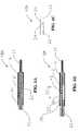
- FIG. 1illustrates an exemplary self-tensioning vascular occlusion device for hemostasis of vascular puncture sites constructed in accordance with the principles of the present invention.
- FIG. 2illustrates an alternative embodiment of the occlusion membrane that may be employed in any of the devices disclosed herein.
- FIGS. 3A and 3Billustrate another embodiment of the expansible member in a retracted configuration and an expanded configuration respectively that may be employed in any of the devices disclosed herein.
- FIGS. 4A and 4Billustrate yet another embodiment of the expansible member in a retracted configuration and an expanded configuration respectively that may be employed in any of the devices disclosed herein.
- FIGS. 5A through 5Cillustrate an alternative embodiment of the deployment means that may be employed in any of the device disclosed herein.
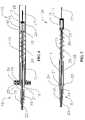
- FIG. 6illustrates a system for hemostasis of a puncture site in a body lumen employing the device of FIG. 1 in conjunction with a loading element.
- FIG. 7illustrates another device for hemostasis of a puncture site in a body lumen employing a locking mechanism.
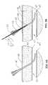
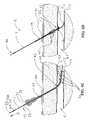
- FIGS. 8A though 8 Dillustrate a method for hemostasis of a puncture site in a body lumen employing the device of FIG. 1 .
- FIGS. 9A through 9Cillustrate another embodiment of the expansible member in a retracted configuration, expanded configuration, and retraction through unwinding process, respectively that may be employed in any of the devices disclosed herein.
- Device 10for hemostasis of vascular puncture sites constructed in accordance with the principles of the present invention is illustrated.
- Device 10comprises a first flexible elongated tubular member 11 having a distal end 12 and a proximal end 13 .
- Tubular member 11may be formed from coiled stainless steel tubing or polymer materials such as nylon, polyurethane, polyimide, PEEK®, PEBAX®, and the like.
- Tubular member 11may have a length in a range from about 10 cm to about 50 cm, preferably in the range from about 15 cm to about 30 cm and a diameter in the range from about 0.25 mm to about 5 mm, preferably in the range from about 0.5 mm to about 2 mm.
- An expansible occlusion member 14is disposed on the distal end 12 of tubular member 11 .
- a tensioning member 26is slidably disposed over the tubular member 11 and proximal the expansible member 14 .
- the expansible member 14may at least partially or preferably be fully covered with an elastomeric membrane material 36 .
- Membrane 36may be formed from a variety of medical grade materials, such as thermoplastic elastomers (e.g., CHRONOPRENE® or POLYBLEND®) having durometers in a range from 15 ⁇ to about 40 ⁇ .
- Membrane 36may be connected at a distal connection point 17 and a proximal connection point 15 .
- Adhesivessuch as LOCTITE® 4014 may be used to attach membrane 36 to the catheter 11 .
- membrane 36may take a form of a sock having its distal end sealed through a heat stake process or the like.
- membrane 36may not have to be attached distally.
- Membrane 36preferably has a diameter that is sufficient to cover the expansible member 14 .
- membrane 36may be designed and attached to facilitate expansible member 14 deployment as well as to reduce the amount of required elongation when the expansible member 14 is deployed. This may be achieved by molding the membrane 36 so that its midpoint diameter, where deployed expansible member 14 has its greatest diameter, is larger than its proximal and distal end diameters (e.g., a spherical shape).
- Membrane 36may also be formed like a tube with a larger diameter than needed (diameter of retracted expansible member 14 ), and then stretched over expansible member 14 and attached.
- the stretchshould be enough to reduce the diameter of the membrane 36 to that of the expansible member 14 . In such a case, when member 14 is deployed, there is less elongation and stress experienced by membrane 36 .
- the membrane 36may additionally form a membrane tip 37 at a distal end 12 A of the catheter 11 so as to provide a soft and blunt point for percutaneous access.
- expansible member 14may be formed from a variety of medical grade materials, including stainless steel, superelastic material such as NITINOL®, or polymer materials such as nylon, polyurethane, polyimide, PEEK®, PEBAX®, and the like.
- the expansible member 14 in a retracted or collapsed statehas a diameter of less than about 3 mm, preferably less than about 1.5 mm, as shown in FIGS. 3A and 4A .
- the expansible member 14 in an expanded statehas a diameter in a range from about 3 mm to about 10 mm, preferably from about 4 mm to about 7 mm, as shown in FIGS. 3B and 4B .
- the expansible member 14may comprise a push or a pull type deployment means as is described in detail co-pending U.S. patent application Ser. No. 10/821,633, assigned to the assignee of the present application and incorporated herein by reference.
- Exemplary expansible member structures 14are described in detail in co-pending U.S. patent application Ser. No. 10/718,504, assigned to the assignee of the present application and incorporated herein by reference.
- Still further embodiments of a braided mesh member 14are disclosed in U.S. Pat. No. 5,836,913, also incorporated herein by reference.
- the expansible member 14comprises a pull type, where the retracted state of the expansible member 14 is its natural, unconstrained free state. Deployment of the expansible member 14 requires that a member 16 be pulled proximally, as denoted by arrow 9 in FIGS. 3A and 4A .
- FIG. 3Aillustrates a malecot member 14 in its natural retracted state and FIG. 3B shows this expansible member 14 in its expanded state at a distal end 12 B of the catheter 11 .
- FIG. 4Aillustrates another embodiment that comprises a tubular braided mesh member 14 in its free retracted state at a distal end 12 C of the catheter.
- FIG. 4Billustrates this expansible member 14 in its deployed expanded configuration. The manner in which these expansible members 14 may be assembled onto the catheter 11 and the way in which these members 14 may interact with other components of the device 10 are similar.
- a proximal end of expansible member 14is connected to the distal end 12 of tubular member 11 at connection point 15 .
- the connectionmay be made with a crimp process, use of shrink tubing such as polyester tubing, adhesives such as glue, heat staking member 14 into member 11 , or a combination thereof.
- a distal end of expansible member 14is connected to the push/pull member 16 at connection point 17 .
- Push/pull member 16may be formed from metals (e.g., stainless steel or NITINOL®) or from polymer materials such as nylon, polyurethane, polyimide, PEEK®, PEBAX®, and the like.
- Member 16has a diameter small enough to go through the tubular member 11 and a length that is long enough to traverse the length of the tubular member 11 .
- the proximal end 13 of members 11 and 16incorporate a handle assembly 18 .
- a first part of the handle 19is connected to the proximal end 13 of member 11 .
- a second part of the handle 20is connected to proximal end of member 16 .
- Handle parts 19 and 20provide for an enhanced grip on members 11 and 16 , allowing the user to more conveniently move these members with respect to each other for the purpose of deploying and retracting the expansible member 14 . Moving parts 19 and 20 away from each other causes the deployment of expansible member 14 and moving them towards each other causes the retraction of expansible member 14 .
- handle assembly 18 Amay be designed to allow the deployed state of expansible member 14 to be held in position. This is because the lack of friction allows members 11 and 16 to move freely with respect to each other forcing the expansible member 14 back to its natural retracted state.
- locking features 21 and 22 of handle parts 19 and 20respectively may be locked to maintain the expansible member 14 in a deployed configuration.
- parts 19 and 20are moved apart until features 21 and 22 completely slide over each other.
- Handle part 20can then be twisted with respect to part 19 by approximately 180° degrees, allowing the proximal end 21 of handle part 19 to rest over the distal end 22 of handle part 20 , as shown in FIG.
- FIG. 5BA top view of this locking mechanism is illustrated in FIG. 5C showing the handle assembly in a deployed position.
- This locking mechanismmay be beneficial to greatly reduce the chances of parts 19 and 20 slipping relative to each other causing unintended retraction.
- a handle housing 35may at least be partially disposed over parts 19 or 20 .
- housing member 35is attached to the first part of the handle 19 and is long enough that when member 14 is deployed and features 23 and 24 are in contact, member 35 extends proximally beyond feature 22 .
- device 10also includes a second flexible tubular member 25 that is slidably disposed over the first tubular member 11 .
- Second member 25is formed from a variety of medical grade materials, including polymer materials such as nylon, polyurethane, polyimide, PEEK®, PEBAX®, and the like. Second member 25 is shorter than first member 11 and may have a length in range from about 5 cm to about 40 cm, preferably in the range from about 10 cm to about 20 cm.
- a distal end of member 25is connected to the tension coil spring 26 .
- Tension coil spring 26encompasses first member 11 , wherein its distal end is connected to member 11 proximal the expansible member 14 at connection point 15 .
- Tensioning member 26may be formed from a variety of medical grade materials, including suitable metals such as stainless steel or preferably shape memory or superelastic metals such as NITINOL®.
- suitable metalssuch as stainless steel or preferably shape memory or superelastic metals such as NITINOL®.
- the amount of force that expansible member 14 can exert against a vessel wall at the puncture siteprimarily depends on the diameter of the wire used, the diameter of the resulting coil, the pitch of the coil, and/or the total number of the loops in the coil of the tensioning member 26 .
- the number of loops in the coil spring 26may be in the range from about 1 loop to about 30 loops, preferably in the range from about 3 loops to about 20 loops.
- the coilsare preferably wound tightly with little or no pitch between the loops when the coil 26 is at its relaxed state.
- the wire diameter used to fabricate the coil 26may be in the range from about 0.02 mm to about 1 mm, preferably in the range from about 0.05 mm to about 0.5 mm.
- the fabricated coil 26may have a diameter in the range from about 1 mm to about 10 mm, preferably in the range from about 1.5 mm to about 5 mm in a relaxed state.
- the diameter of the tension coil spring 26 in the preferred embodiment of this inventionis chosen to be greater than the inside diameter of a delivery sheath. For example, when a 5 Fr sheath is used the diameter of coil 26 would be greater than 1.75 mm.
- the distal end 12 of device 10may include a tip deflector 27 .
- Deflector 27prevents element 17 from damaging the vessel wall on the opposite side of the puncture site. This may happen if the user excessively compresses the skin at or adjacent to the puncture site, which potentially could happen when the device 10 is being removed.
- Deflector 27may be formed from a variety of medical grade materials, including flexible metal coil materials or polymer materials such as nylon, polyurethane, polyimide, PEEK®, PEBAX®, and the like. In one embodiment, deflector 27 may be formed from a small diameter wire, possibly the extension of member 16 , coated with a soft polymer material.
- Deflector 27will generally have a diameter equal to or smaller than the catheter diameter at element 17 and a length in the range from about 1 cm to about 10 cm, preferably from about 2 cm to about 4 cm. A welding process may be utilized to provide for a short and strong connection point at element 17 . It will be appreciated however that the need for a deflector tip 27 may be alleviated if element 17 itself is made short and blunt.
- device 10may be equipped with a catheter loading element 28 when tensioning member 26 at its relaxed state is larger than the inner diameter of the delivery sheath in order to facilitate insertion of the device 10 through the sheath.
- Loading element 28generally comprises an elongated tubular member 29 .
- An outer diameter of member 29is smaller than the opening in a hub of the sheath and can penetrate a seal in the sheath.
- An inner diameter of loader 28is large enough to allow the catheter 11 to completely slide through.
- Loader 28has a length long enough to at least contain all the elements of the catheter 11 distal to and including the tensioning member 26 .
- Loader 28may include a feature 30 at a proximal end.
- This feature 30may be used as a stop against the hub of the introducer sheath, preventing the loading element 28 from completely sliding into a lumen of the sheath.
- Loading element 28may be formed from coiled stainless steel tubing or polymer materials such as nylon, polyurethane, polyimide, PEEK®, PEBAX®, and the like.
- introduction of the device 10 A into the sheath and removal of the device 10 A from the bodymay also be facilitated by incorporating a locking mechanism 33 at a proximal end of second tubular member 25 that may be interlocked with a feature 34 on a distal end of handle 19 .
- the locking mechanism 33 , 34allows tensioning member 26 to be maintained in a stretched state so as to reduce the coil diameter to below that of the inner diameter of the delivery sheath and thereby allowing the device 10 A to slide through the sheath without interference.
- locking features on the catheter 11may interlock with the locking mechanism 33 on member 25 . Even when member 25 is equipped with an interlocking mechanism 33 so that tensioning member 26 does not interfere with the sheath, loader 28 may still provide for enhanced introduction of the device 10 A into the sheath.
- tubular member 11has a visual mark 31 .
- alignment of mark 31 with the opening of the hub of the sheathindicates that catheter 10 has been advanced enough through the sheath to expose the expansible member 14 in the lumen of the vessel.
- element 30 of loading element 28is against the hub of the sheath
- alignment of mark 31 with the proximal end of feature 30may indicate appropriate advancement of the expansible member 14 in the vessel lumen.
- alignment of the distal end of handle 19 with the hub of the sheath or loading element 30may eliminate the need for mark 31 .
- mechanical meansmay be utilized for proper location of the expansible member 14 within the lumen of the vessel.
- FIG. 8Adepicts an existing delivery sheath 40 through an opening in a skin surface 46 , tissue tract in fascia 45 , and vessel wall 43 and seated in a vessel lumen 41 at the completion of an interventional procedure.
- Device 10 including loading element 28is then inserted through the hub of the sheath 40 so that loading element 28 at least penetrates the seal of sheath 40 or until feature 30 is against the hub of the sheath 40 , as shown in FIG. 8B .
- Loader 28may now be removed.
- device 10 with loader 28 presentcan be pushed into sheath 40 until the identifying mark 31 on member 11 is aligned with feature 30 of loading element 28 .
- expansible member 14is then deployed by holding part 19 of handle assembly 18 A stationary and moving member 20 proximally, as depicted by arrow 8 and described in detail with respect to FIGS. 5A through 5C .
- Second tubular member 25may then be pulled proximally until resistance is felt indicating that expansible member 14 is at the distal end of sheath 40 . If member 25 is equipped with a locking mechanism 33 in a locked position, member 11 or the handle assembly 18 A may be grasped to pull the device 10 proximally and seat member 14 against the tip of the sheath 40 .
- the sheath 40 at the hubmay be gently removed from the body so as to seat the expansible member 14 .
- sheath 40is removed from the body exposing the loops of the coil 26 and lodging them into the fascia 45 one loop at a time. Loader 28 along with sheath 40 are removed and may be discarded.
- the interference between the loops of the coil 26 and fascia 45provides the hold and retains expansible member 14 under tension against the vessel wall 43 at the puncture site 42 .
- the tension applied to the expansible member 14is sufficient for complete hemostasis, typically in a range from about 0.5 ounce to 30 ounces.
- the sheath 40 and/or loader 28are removed and the coil 26 gets embedded in the tissue 45 , the amount of the tension at the puncture site 42 may drop as the coil 26 recoils some to engage itself in the tissue 45 .
- the amount in the reduction of tensionis dependant on the tissue type 45 surrounding the puncture site 42 , the nature of the coil spring 26 , and the thickness of the fascia 45 . These factors have been considered in the proper design of the coil 26 of the present invention.
- second tubular member 25may be moved proximally and released increasing the amount of compression that expansible member 14 applies on the vessel wall 43 .
- the increase in the pull forcemay be limited by the amount of proximal movement of member 25 , which can be determined by the proper length of member 25 and the distance between the proximal end of member 25 and distal end of handle part 19 .
- the pull forcemay be limited by interference of members 25 and 19 .
- the pull forcemay also be limited by interference between the coil 26 and the first tubular member 11 . In particular, the closer the diameter of member 11 to the inside diameter of coil 26 , the less stretch member 26 can experience before the coil diameter is reduced enough to interfere with member 11 . In the above methodologies, when second member 25 stops moving respect to first member 11 , that may be an indication that the maximum allowable and safe pull force has been reached.
- Device 10remains in the body for an adequate period of time. Occlusive compression may be applied proximal to the puncture site 42 when the device 10 is to be removed. Expansible member 14 is retracted by manipulation of handle assembly 18 A and member 25 is grasped so as to pull the device 10 out of the body. Pulling on member 25 causes coil 26 to stretch, reducing the coil diameter, and consequently reducing the amount of interference between coil 26 and fascia 45 . If device 10 is equipped with locking features 33 and 34 , removal of device 10 may be accomplished by first pulling on member 25 proximally and interlocking features 33 and 34 . This easily disengages device 10 from the fascia 45 . Removal of the device 10 may be followed by a few minutes of manual compression at the skin surface 46 to achieve complete hemostasis.
- device 10may include an external clip 50 .
- Clip 50couples member 25 and rests on the patient's skin surface 46 .
- Clip 50may be used as a safety feature to further secure and keep expansible member 14 under tension. It may also be used when greater tension is desired than that provided by interaction of coil 26 with sheath 40 and fascia 45 alone.
- coil member 26may be intended to function only as a tensioning member.
- Coil 26 in this embodimentmay have a diameter smaller than the inner diameter of the sheath 40 and be formed from elastomeric material. This elastomeric member is preferably in a form of a tube which is attached to the first member 11 at point 15 and to the distal end of second member 25 .
- member 25is used to place expansible member 14 against the vessel wall 43 at the puncture site 42 and to apply the required tension to the device 10 .
- the substantial hold once the tension is appliedis then provided by external means, such as the external clip 50 .
- This device 10may have the advantage of being easier to load and insert through the sheath 40 as the external clip 50 provides anchoring.
- the expansible member 60preferably comprises coiled string constructed from small diameter tubing that is flexible.
- the tubular configurationmay have a suture or small diameter wire in its lumen to add to its tensile strength.
- Flexible member 60may be formed from medical grade materials, including polymer materials such as nylon, polyurethane, polyimide, PEEK®, PEBAX®, and the like. Flexible member 60 can be coiled into an expanded configuration comprising a disc or dome shape 61 . Adjacent loops of member 60 may be adhered lightly through a heating or a gluing process.
- FIG. 9AMember 60 at the center is fed through a tube 62 , wrapped around tube 62 , and is housed in a tubular member 63 , as shown in FIG. 9A .
- tube 62is pushed forward to expose the expansible member 61 .
- the expansible member 61unfolds into a disc or a dome configuration as illustrated in FIG. 9B .
- the sealing processis attained by pulling on tube 62 , allowing the expansible member 61 to press against the puncture site.
- Retractionis effected by pulling coil 60 through tube 62 , causing the loops of the expansible member 61 to unwind as depicted by FIG. 9C .
- Still further embodiments of such an expansible memberare disclosed in U.S. Patent Application No. 2003/0120291, which describes a temporary seal and method for facilitating anastomosis and is also incorporated herein by reference.
Landscapes
- Health & Medical Sciences (AREA)
- Surgery (AREA)
- Life Sciences & Earth Sciences (AREA)
- Biomedical Technology (AREA)
- Nuclear Medicine, Radiotherapy & Molecular Imaging (AREA)
- Engineering & Computer Science (AREA)
- Cardiology (AREA)
- Heart & Thoracic Surgery (AREA)
- Medical Informatics (AREA)
- Molecular Biology (AREA)
- Animal Behavior & Ethology (AREA)
- General Health & Medical Sciences (AREA)
- Public Health (AREA)
- Veterinary Medicine (AREA)
- Surgical Instruments (AREA)
Abstract
Description
Claims (14)
Priority Applications (7)
| Application Number | Priority Date | Filing Date | Title |
|---|---|---|---|
| US10/857,177US7572274B2 (en) | 2004-05-27 | 2004-05-27 | Self-tensioning vascular occlusion device and method for its use |
| US10/974,008US7993366B2 (en) | 2004-05-27 | 2004-10-25 | Self-tensioning vascular occlusion device and method for its use |
| EP05759503.5AEP1748733B1 (en) | 2004-05-27 | 2005-05-18 | Self-tensioning vascular occlusion device |
| PCT/US2005/017688WO2005117715A2 (en) | 2004-05-27 | 2005-05-18 | Self-tensioning vascular occlusion device and method for its use |
| JP2007515192AJP4954063B2 (en) | 2004-05-27 | 2005-05-18 | Hemostatic device |
| US12/498,278US8439944B2 (en) | 2004-05-27 | 2009-07-06 | Self-tensioning vascular occlusion device and method for its use |
| US13/868,775US9427221B2 (en) | 2004-04-09 | 2013-04-23 | Hemostasis-enhancing device and method for its use |
Applications Claiming Priority (1)
| Application Number | Priority Date | Filing Date | Title |
|---|---|---|---|
| US10/857,177US7572274B2 (en) | 2004-05-27 | 2004-05-27 | Self-tensioning vascular occlusion device and method for its use |
Related Child Applications (2)
| Application Number | Title | Priority Date | Filing Date |
|---|---|---|---|
| US10/974,008Continuation-In-PartUS7993366B2 (en) | 2004-04-09 | 2004-10-25 | Self-tensioning vascular occlusion device and method for its use |
| US12/498,278DivisionUS8439944B2 (en) | 2004-05-27 | 2009-07-06 | Self-tensioning vascular occlusion device and method for its use |
Publications (2)
| Publication Number | Publication Date |
|---|---|
| US20050277980A1 US20050277980A1 (en) | 2005-12-15 |
| US7572274B2true US7572274B2 (en) | 2009-08-11 |
Family
ID=35426404
Family Applications (2)
| Application Number | Title | Priority Date | Filing Date |
|---|---|---|---|
| US10/857,177Active2025-11-04US7572274B2 (en) | 2004-04-09 | 2004-05-27 | Self-tensioning vascular occlusion device and method for its use |
| US12/498,278Active2025-12-01US8439944B2 (en) | 2004-05-27 | 2009-07-06 | Self-tensioning vascular occlusion device and method for its use |
Family Applications After (1)
| Application Number | Title | Priority Date | Filing Date |
|---|---|---|---|
| US12/498,278Active2025-12-01US8439944B2 (en) | 2004-05-27 | 2009-07-06 | Self-tensioning vascular occlusion device and method for its use |
Country Status (1)
| Country | Link |
|---|---|
| US (2) | US7572274B2 (en) |
Cited By (23)
| Publication number | Priority date | Publication date | Assignee | Title |
|---|---|---|---|---|
| US20060271078A1 (en)* | 2005-05-12 | 2006-11-30 | Modesitt D B | Access and closure device and method |
| US20090254110A1 (en)* | 2008-04-04 | 2009-10-08 | Accessclosure, Inc. | Apparatus and Methods for Sealing a Vascular Puncture |
| US20090275978A1 (en)* | 2004-05-27 | 2009-11-05 | Cardiva Medical, Inc. | Self-tensioning vascular occlusion device and method for its use |
| US20100125296A1 (en)* | 2004-07-10 | 2010-05-20 | Modesitt D Bruce | Biological tissue closure device and method |
| US20100152748A1 (en)* | 2008-12-12 | 2010-06-17 | E-Pacing, Inc. | Devices, Systems, and Methods Providing Body Lumen Access |
| EP2292147A1 (en) | 2009-09-07 | 2011-03-09 | Jönsson, Anders | Device and kit for closure of a body lumen puncture |
| US8114054B2 (en)* | 2005-05-23 | 2012-02-14 | Venetec International, Inc. | Medical article anchoring system |
| EP2497426A1 (en) | 2011-03-09 | 2012-09-12 | Aeeg Ab | Device, kit and method for closure of a body lumen puncture |
| US8444671B2 (en) | 2006-12-21 | 2013-05-21 | Cardiva Medical, Inc. | Hemostasis-enhancing device and method for its use |
| US8506592B2 (en) | 2008-08-26 | 2013-08-13 | St. Jude Medical, Inc. | Method and system for sealing percutaneous punctures |
| US8562623B2 (en) | 2011-02-09 | 2013-10-22 | ROSS ALAN McDONALD | Vaginal occlusion device |
| US8845682B2 (en) | 2009-10-13 | 2014-09-30 | E-Pacing, Inc. | Vasculature closure devices and methods |
| US8979882B2 (en) | 2008-07-21 | 2015-03-17 | Arstasis, Inc. | Devices, methods, and kits for forming tracts in tissue |
| US9119948B2 (en) | 2013-02-20 | 2015-09-01 | Covidien Lp | Occlusive implants for hollow anatomical structures, delivery systems, and related methods |
| US9364206B2 (en) | 2008-04-04 | 2016-06-14 | Access Closure, Inc. | Apparatus and methods for sealing a vascular puncture |
| US10085731B2 (en) | 2013-07-15 | 2018-10-02 | E-Pacing, Inc. | Vasculature closure devices and methods |
| US10363021B2 (en) | 2005-12-13 | 2019-07-30 | Cardiva Medical, Inc. | Vascular closure devices and methods providing hemostatic enhancement |
| US10441753B2 (en) | 2012-05-25 | 2019-10-15 | Arstasis, Inc. | Vascular access configuration |
| US10675447B2 (en) | 2012-05-25 | 2020-06-09 | Arstasis, Inc. | Vascular access configuration |
| US10960100B2 (en) | 2012-06-22 | 2021-03-30 | Z-Medica, Llc | Hemostatic devices |
| US10960101B2 (en) | 2006-05-26 | 2021-03-30 | Z-Medica, Llc | Clay-based hemostatic agents |
| US11007218B2 (en) | 2010-09-22 | 2021-05-18 | Z-Medica, Llc | Hemostatic compositions, devices, and methods |
| US11167058B2 (en) | 2005-02-15 | 2021-11-09 | Virginia Commonwealth University | Hemostasis of wound having high pressure blood flow |
Families Citing this family (17)
| Publication number | Priority date | Publication date | Assignee | Title |
|---|---|---|---|---|
| US7223266B2 (en) | 2003-02-04 | 2007-05-29 | Cardiodex Ltd. | Methods and apparatus for hemostasis following arterial catheterization |
| US20050267520A1 (en) | 2004-05-12 | 2005-12-01 | Modesitt D B | Access and closure device and method |
| EP1814478A4 (en) | 2004-11-22 | 2011-05-18 | Cardiodex Ltd | Techniques for heat-treating varicose veins |
| US8911472B2 (en) | 2005-12-13 | 2014-12-16 | Cardiva Medical, Inc. | Apparatus and methods for delivering hemostatic materials for blood vessel closure |
| US7691127B2 (en)* | 2005-12-13 | 2010-04-06 | Cardiva Medical, Inc. | Drug eluting vascular closure devices and methods |
| US20070265658A1 (en)* | 2006-05-12 | 2007-11-15 | Aga Medical Corporation | Anchoring and tethering system |
| WO2008033964A2 (en) | 2006-09-13 | 2008-03-20 | Accessclosure, Inc. | Apparatus for sealing a vascular puncture |
| US8475489B2 (en)* | 2007-07-13 | 2013-07-02 | Percutaneous Systems, Inc. | Apparatus for occluding body lumens |
| EP2182875A4 (en) | 2007-08-15 | 2011-08-24 | Cardiodex Ltd | Systems and methods for puncture closure |
| WO2010056915A1 (en)* | 2008-11-12 | 2010-05-20 | Accessclosure, Inc. | Apparatus and methods for sealing a vascular puncture |
| WO2010065556A1 (en) | 2008-12-01 | 2010-06-10 | Percutaneous Systems, Inc. | Methods and systems for capturing and removing urinary stones from body cavities |
| WO2011005971A1 (en) | 2009-07-09 | 2011-01-13 | Cook Incorporated | Spring action medical device |
| US20110106012A1 (en)* | 2009-10-29 | 2011-05-05 | Velarde Franz E | Sheath Introducer with Self-Anchoring Mechanism |
| WO2013081905A1 (en)* | 2011-11-28 | 2013-06-06 | St. Jude Medical Puerto Rico Llc | Anchor device for large bore vascular closure |
| US9924903B2 (en)* | 2012-12-27 | 2018-03-27 | Volcano Corporation | Pressure-sensing guide wire with sliding pressure sensor |
| GB201307965D0 (en) | 2013-05-02 | 2013-06-12 | Cook Medical Technologies Llc | Vascular plug |
| CN118216965B (en)* | 2024-05-23 | 2024-09-17 | 鼎科医疗技术(苏州)有限公司 | Vascular occluder |
Citations (65)
| Publication number | Priority date | Publication date | Assignee | Title |
|---|---|---|---|---|
| US4744364A (en) | 1987-02-17 | 1988-05-17 | Intravascular Surgical Instruments, Inc. | Device for sealing percutaneous puncture in a vessel |
| US4850975A (en) | 1987-03-27 | 1989-07-25 | Yuichi Furukawa | Catheter introducer for angiography |
| US4852568A (en) | 1987-02-17 | 1989-08-01 | Kensey Nash Corporation | Method and apparatus for sealing an opening in tissue of a living being |
| US4890612A (en) | 1987-02-17 | 1990-01-02 | Kensey Nash Corporation | Device for sealing percutaneous puncture in a vessel |
| US5061274A (en) | 1989-12-04 | 1991-10-29 | Kensey Nash Corporation | Plug device for sealing openings and method of use |
| US5108421A (en) | 1990-10-01 | 1992-04-28 | Quinton Instrument Company | Insertion assembly and method of inserting a vessel plug into the body of a patient |
| US5108420A (en) | 1991-02-01 | 1992-04-28 | Temple University | Aperture occlusion device |
| US5171259A (en) | 1990-04-02 | 1992-12-15 | Kanji Inoue | Device for nonoperatively occluding a defect |
| WO1992022252A1 (en) | 1991-06-18 | 1992-12-23 | Ashridge Ag | Sealing device for a blood vessel or the like |
| US5197971A (en) | 1990-03-02 | 1993-03-30 | Bonutti Peter M | Arthroscopic retractor and method of using the same |
| US5258000A (en) | 1991-11-25 | 1993-11-02 | Cook Incorporated | Tissue aperture repair device |
| US5290552A (en) | 1988-05-02 | 1994-03-01 | Matrix Pharmaceutical, Inc./Project Hear | Surgical adhesive material |
| US5292332A (en) | 1992-07-27 | 1994-03-08 | Lee Benjamin I | Methods and device for percutanceous sealing of arterial puncture sites |
| US5383896A (en) | 1993-05-25 | 1995-01-24 | Gershony; Gary | Vascular sealing device |
| WO1995005121A1 (en) | 1993-08-12 | 1995-02-23 | Vascular Technologies, Inc. | Catheter introducer with suture capability |
| US5419765A (en) | 1990-12-27 | 1995-05-30 | Novoste Corporation | Wound treating device and method for treating wounds |
| US5437631A (en) | 1990-09-21 | 1995-08-01 | Datascope Investment Corp. | Percutaneous introducer set and method for sealing puncture wounds |
| US5454833A (en) | 1993-07-21 | 1995-10-03 | Laboratoire, Nycomed S.A. | System for temporarily obturating an orifice in a perforated organ, such as a vessel |
| US5456667A (en) | 1993-05-20 | 1995-10-10 | Advanced Cardiovascular Systems, Inc. | Temporary stenting catheter with one-piece expandable segment |
| US5486195A (en) | 1993-07-26 | 1996-01-23 | Myers; Gene | Method and apparatus for arteriotomy closure |
| US5507744A (en) | 1992-04-23 | 1996-04-16 | Scimed Life Systems, Inc. | Apparatus and method for sealing vascular punctures |
| WO1996024290A1 (en) | 1995-02-10 | 1996-08-15 | Sherwood Medical Company | Assembly for sealing a puncture in a vessel |
| US5626601A (en) | 1995-10-27 | 1997-05-06 | Gary Gershony | Vascular sealing apparatus and method |
| US5630833A (en) | 1992-07-16 | 1997-05-20 | Sherwood Medical Company | Device for sealing hemostatic incisions |
| US5634936A (en) | 1995-02-06 | 1997-06-03 | Scimed Life Systems, Inc. | Device for closing a septal defect |
| US5728134A (en) | 1996-09-17 | 1998-03-17 | Barak; Shlomo | Method and apparatus for hemostasis |
| US5782860A (en) | 1997-02-11 | 1998-07-21 | Biointerventional Corporation | Closure device for percutaneous occlusion of puncture sites and tracts in the human body and method |
| WO1998040017A2 (en) | 1997-03-12 | 1998-09-17 | Advanced Closure Systems, Inc. | Vascular sealing device |
| US5810810A (en) | 1992-04-23 | 1998-09-22 | Scimed Life Systems, Inc. | Apparatus and method for sealing vascular punctures |
| US5836913A (en) | 1997-05-02 | 1998-11-17 | Innerdyne, Inc. | Device and method for accessing a body cavity |
| US5851210A (en) | 1997-03-21 | 1998-12-22 | Torossian; Richard | Stent delivery system and method |
| US5861003A (en) | 1996-10-23 | 1999-01-19 | The Cleveland Clinic Foundation | Apparatus and method for occluding a defect or aperture within body surface |
| US5868778A (en) | 1995-10-27 | 1999-02-09 | Vascular Solutions, Inc. | Vascular sealing apparatus and method |
| US5895398A (en) | 1996-02-02 | 1999-04-20 | The Regents Of The University Of California | Method of using a clot capture coil |
| US5951583A (en) | 1993-05-25 | 1999-09-14 | Vascular Solutions, Inc. | Thrombin and collagen procoagulant and process for making the same |
| US5951589A (en) | 1997-02-11 | 1999-09-14 | Biointerventional Corporation | Expansile device for use in blood vessels and tracts in the body and tension application device for use therewith and method |
| US6012457A (en) | 1997-07-08 | 2000-01-11 | The Regents Of The University Of California | Device and method for forming a circumferential conduction block in a pulmonary vein |
| US6017359A (en) | 1993-05-25 | 2000-01-25 | Vascular Solutions, Inc. | Vascular sealing apparatus |
| WO2000006029A1 (en) | 1998-07-31 | 2000-02-10 | Biointerventional Corporation | Expansile device for use in blood vessels ans tracts in the body and method |
| US6048358A (en) | 1998-07-13 | 2000-04-11 | Barak; Shlomo | Method and apparatus for hemostasis following arterial catheterization |
| US6056770A (en) | 1997-02-11 | 2000-05-02 | Biointerventional Corporation | Expansile device for use in blood vessels and tracts in the body and method |
| US6080182A (en) | 1996-12-20 | 2000-06-27 | Gore Enterprise Holdings, Inc. | Self-expanding defect closure device and method of making and using |
| US6146396A (en) | 1999-03-05 | 2000-11-14 | Board Of Regents, The University Of Texas System | Declotting method and apparatus |
| US6179860B1 (en)* | 1998-08-19 | 2001-01-30 | Artemis Medical, Inc. | Target tissue localization device and method |
| US6213988B1 (en)* | 1998-02-10 | 2001-04-10 | Medtronic, Inc. | Introducer with external hemostasis clip |
| US6248124B1 (en) | 1999-02-22 | 2001-06-19 | Tyco Healthcare Group | Arterial hole closure apparatus |
| US6296657B1 (en) | 1998-10-07 | 2001-10-02 | Gregory G. Brucker | Vascular sealing device and method |
| US20010034537A1 (en)* | 1996-12-20 | 2001-10-25 | Shaw Edward E. | Self-expanding defect closure device and method of making and using |
| US20020065536A1 (en)* | 1999-08-30 | 2002-05-30 | Applied Medical Resources Corporation | Surgical clip |
| US20020072767A1 (en) | 2000-08-02 | 2002-06-13 | Zhu Yong Hua | Method and apparatus for closing vascular puncture using hemostatic material |
| US20020072768A1 (en)* | 2000-12-07 | 2002-06-13 | Ginn Richard S. | Apparatus and methods for providing tactile feedback while delivering a closure device |
| US20020133123A1 (en) | 2001-03-14 | 2002-09-19 | Cardiodex | Balloon method and apparatus for vascular closure following arterial catheterization |
| US6464712B1 (en)* | 1997-02-11 | 2002-10-15 | Biointerventional Corporation | Expansile device for use in blood vessels and tracts in the body and method |
| US20030120291A1 (en) | 2001-12-26 | 2003-06-26 | Chin Albert K. | Temporary seal and method for facilitating anastomosis |
| US20030176875A1 (en) | 2002-03-07 | 2003-09-18 | Anderson Kimberly A. | Transobturator surgical articles and methods |
| US20030191493A1 (en) | 2002-04-05 | 2003-10-09 | Epstein Gordon H. | Device for clot retrieval and distal protection |
| US20030225420A1 (en)* | 2002-03-11 | 2003-12-04 | Wardle John L. | Surgical coils and methods of deploying |
| US20040176798A1 (en) | 1997-02-11 | 2004-09-09 | Cardiva Medical, Inc. | Expansile device for use in blood vessels and tracts in the body and method |
| US20050038453A1 (en) | 2003-08-13 | 2005-02-17 | Medical Components, Inc. | Conduit retaining clip |
| US6913614B2 (en) | 2003-05-08 | 2005-07-05 | Cardia, Inc. | Delivery system with safety tether |
| US6994689B1 (en)* | 1995-06-05 | 2006-02-07 | Medtronic Vascular, Inc. | Occlusion of a vessel |
| US7025776B1 (en) | 2001-04-24 | 2006-04-11 | Advanced Catheter Engineering, Inc. | Arteriotomy closure devices and techniques |
| US7115127B2 (en) | 2003-02-04 | 2006-10-03 | Cardiodex, Ltd. | Methods and apparatus for hemostasis following arterial catheterization |
| US7220246B2 (en)* | 2004-07-14 | 2007-05-22 | Medical Components, Inc. | Catheter hub clip |
| US7223266B2 (en) | 2003-02-04 | 2007-05-29 | Cardiodex Ltd. | Methods and apparatus for hemostasis following arterial catheterization |
Family Cites Families (18)
| Publication number | Priority date | Publication date | Assignee | Title |
|---|---|---|---|---|
| US120291A (en)* | 1871-10-24 | Improvement in automatic circuit-closers for telegraph apparatus | ||
| US1333123A (en)* | 1917-02-13 | 1920-03-09 | Charles F Mcbee | Bookbinding-machine |
| US4721507A (en)* | 1986-06-05 | 1988-01-26 | Thomas J. Fogarty | Shear force gauge and method and apparatus for limiting embolectomy shear force |
| US5300073A (en)* | 1990-10-05 | 1994-04-05 | Salut, Ltd. | Sacral implant system |
| US5603713A (en)* | 1991-09-24 | 1997-02-18 | Aust; Gilbert M. | Anterior lumbar/cervical bicortical compression plate |
| US5222974A (en)* | 1991-11-08 | 1993-06-29 | Kensey Nash Corporation | Hemostatic puncture closure system and method of use |
| US5282827A (en)* | 1991-11-08 | 1994-02-01 | Kensey Nash Corporation | Hemostatic puncture closure system and method of use |
| US5645566A (en)* | 1995-09-15 | 1997-07-08 | Sub Q Inc. | Apparatus and method for percutaneous sealing of blood vessel punctures |
| US6071300A (en) | 1995-09-15 | 2000-06-06 | Sub-Q Inc. | Apparatus and method for percutaneous sealing of blood vessel punctures |
| US6371975B2 (en)* | 1998-11-06 | 2002-04-16 | Neomend, Inc. | Compositions, systems, and methods for creating in situ, chemically cross-linked, mechanical barriers |
| US7279001B2 (en) | 1998-11-06 | 2007-10-09 | Neomend, Inc. | Systems, methods, and compositions for achieving closure of vascular puncture sites |
| US6984219B2 (en)* | 1999-09-23 | 2006-01-10 | Mark Ashby | Depth and puncture control for blood vessel hemostasis system |
| CA2448900C (en)* | 2001-06-08 | 2011-05-17 | Morris Innovative Research, Inc. | Method and apparatus for sealing access |
| US7125821B2 (en)* | 2003-09-05 | 2006-10-24 | Exxonmobil Chemical Patents Inc. | Low metal content catalyst compositions and processes for making and using same |
| JP4955534B2 (en) | 2004-03-22 | 2012-06-20 | アクセスクロージャー,インク. | Device for sealing vascular perforations |
| US7572274B2 (en)* | 2004-05-27 | 2009-08-11 | Cardiva Medical, Inc. | Self-tensioning vascular occlusion device and method for its use |
| US7993366B2 (en)* | 2004-05-27 | 2011-08-09 | Cardiva Medical, Inc. | Self-tensioning vascular occlusion device and method for its use |
| US9017374B2 (en)* | 2004-04-09 | 2015-04-28 | Cardiva Medical, Inc. | Device and method for sealing blood vessels |
- 2004
- 2004-05-27USUS10/857,177patent/US7572274B2/enactiveActive
- 2009
- 2009-07-06USUS12/498,278patent/US8439944B2/enactiveActive
Patent Citations (72)
| Publication number | Priority date | Publication date | Assignee | Title |
|---|---|---|---|---|
| US4744364A (en) | 1987-02-17 | 1988-05-17 | Intravascular Surgical Instruments, Inc. | Device for sealing percutaneous puncture in a vessel |
| US4852568A (en) | 1987-02-17 | 1989-08-01 | Kensey Nash Corporation | Method and apparatus for sealing an opening in tissue of a living being |
| US4890612A (en) | 1987-02-17 | 1990-01-02 | Kensey Nash Corporation | Device for sealing percutaneous puncture in a vessel |
| US4850975A (en) | 1987-03-27 | 1989-07-25 | Yuichi Furukawa | Catheter introducer for angiography |
| US5290552A (en) | 1988-05-02 | 1994-03-01 | Matrix Pharmaceutical, Inc./Project Hear | Surgical adhesive material |
| US5061274A (en) | 1989-12-04 | 1991-10-29 | Kensey Nash Corporation | Plug device for sealing openings and method of use |
| US5197971A (en) | 1990-03-02 | 1993-03-30 | Bonutti Peter M | Arthroscopic retractor and method of using the same |
| US5171259A (en) | 1990-04-02 | 1992-12-15 | Kanji Inoue | Device for nonoperatively occluding a defect |
| US5437631A (en) | 1990-09-21 | 1995-08-01 | Datascope Investment Corp. | Percutaneous introducer set and method for sealing puncture wounds |
| US5108421A (en) | 1990-10-01 | 1992-04-28 | Quinton Instrument Company | Insertion assembly and method of inserting a vessel plug into the body of a patient |
| US5419765A (en) | 1990-12-27 | 1995-05-30 | Novoste Corporation | Wound treating device and method for treating wounds |
| US5108420A (en) | 1991-02-01 | 1992-04-28 | Temple University | Aperture occlusion device |
| WO1992022252A1 (en) | 1991-06-18 | 1992-12-23 | Ashridge Ag | Sealing device for a blood vessel or the like |
| US5258000A (en) | 1991-11-25 | 1993-11-02 | Cook Incorporated | Tissue aperture repair device |
| US5810810A (en) | 1992-04-23 | 1998-09-22 | Scimed Life Systems, Inc. | Apparatus and method for sealing vascular punctures |
| US5507744A (en) | 1992-04-23 | 1996-04-16 | Scimed Life Systems, Inc. | Apparatus and method for sealing vascular punctures |
| US5630833A (en) | 1992-07-16 | 1997-05-20 | Sherwood Medical Company | Device for sealing hemostatic incisions |
| US5292332A (en) | 1992-07-27 | 1994-03-08 | Lee Benjamin I | Methods and device for percutanceous sealing of arterial puncture sites |
| US5456667A (en) | 1993-05-20 | 1995-10-10 | Advanced Cardiovascular Systems, Inc. | Temporary stenting catheter with one-piece expandable segment |
| US6017359A (en) | 1993-05-25 | 2000-01-25 | Vascular Solutions, Inc. | Vascular sealing apparatus |
| US5951583A (en) | 1993-05-25 | 1999-09-14 | Vascular Solutions, Inc. | Thrombin and collagen procoagulant and process for making the same |
| US5383896A (en) | 1993-05-25 | 1995-01-24 | Gershony; Gary | Vascular sealing device |
| US5957952A (en) | 1993-05-25 | 1999-09-28 | Vascular Solutions, Inc. | Vascular sealing device |
| US5454833A (en) | 1993-07-21 | 1995-10-03 | Laboratoire, Nycomed S.A. | System for temporarily obturating an orifice in a perforated organ, such as a vessel |
| US5486195A (en) | 1993-07-26 | 1996-01-23 | Myers; Gene | Method and apparatus for arteriotomy closure |
| WO1995005121A1 (en) | 1993-08-12 | 1995-02-23 | Vascular Technologies, Inc. | Catheter introducer with suture capability |
| US5634936A (en) | 1995-02-06 | 1997-06-03 | Scimed Life Systems, Inc. | Device for closing a septal defect |
| WO1996024290A1 (en) | 1995-02-10 | 1996-08-15 | Sherwood Medical Company | Assembly for sealing a puncture in a vessel |
| US6994689B1 (en)* | 1995-06-05 | 2006-02-07 | Medtronic Vascular, Inc. | Occlusion of a vessel |
| US5626601A (en) | 1995-10-27 | 1997-05-06 | Gary Gershony | Vascular sealing apparatus and method |
| US5868778A (en) | 1995-10-27 | 1999-02-09 | Vascular Solutions, Inc. | Vascular sealing apparatus and method |
| US5895398A (en) | 1996-02-02 | 1999-04-20 | The Regents Of The University Of California | Method of using a clot capture coil |
| US5728134A (en) | 1996-09-17 | 1998-03-17 | Barak; Shlomo | Method and apparatus for hemostasis |
| US5861003A (en) | 1996-10-23 | 1999-01-19 | The Cleveland Clinic Foundation | Apparatus and method for occluding a defect or aperture within body surface |
| US20010034537A1 (en)* | 1996-12-20 | 2001-10-25 | Shaw Edward E. | Self-expanding defect closure device and method of making and using |
| US6080182A (en) | 1996-12-20 | 2000-06-27 | Gore Enterprise Holdings, Inc. | Self-expanding defect closure device and method of making and using |
| US5922009A (en) | 1997-02-11 | 1999-07-13 | Biointerventional Coporation | Expansile device for use in blood vessels and tracts in the body and tension application device for use therewith and method |
| US20040176798A1 (en) | 1997-02-11 | 2004-09-09 | Cardiva Medical, Inc. | Expansile device for use in blood vessels and tracts in the body and method |
| US5951589A (en) | 1997-02-11 | 1999-09-14 | Biointerventional Corporation | Expansile device for use in blood vessels and tracts in the body and tension application device for use therewith and method |
| WO1998034546A1 (en) | 1997-02-11 | 1998-08-13 | Biointerventional Corporation | Expansile device for use in blood vessels and tracts in the body and tension application device for use therewith and method |
| US6656207B2 (en) | 1997-02-11 | 2003-12-02 | Biointerventional Corporation | Expansile device for use in blood vessels and tracts in the body and method |
| US6464712B1 (en)* | 1997-02-11 | 2002-10-15 | Biointerventional Corporation | Expansile device for use in blood vessels and tracts in the body and method |
| US5782860A (en) | 1997-02-11 | 1998-07-21 | Biointerventional Corporation | Closure device for percutaneous occlusion of puncture sites and tracts in the human body and method |
| US6056770A (en) | 1997-02-11 | 2000-05-02 | Biointerventional Corporation | Expansile device for use in blood vessels and tracts in the body and method |
| US6056769A (en) | 1997-02-11 | 2000-05-02 | Biointerventional Corporation | Expansile device for use in blood vessels and tracts in the body and tension application device for use therewith and method |
| WO1998040017A2 (en) | 1997-03-12 | 1998-09-17 | Advanced Closure Systems, Inc. | Vascular sealing device |
| US5851210A (en) | 1997-03-21 | 1998-12-22 | Torossian; Richard | Stent delivery system and method |
| US5836913A (en) | 1997-05-02 | 1998-11-17 | Innerdyne, Inc. | Device and method for accessing a body cavity |
| US6012457A (en) | 1997-07-08 | 2000-01-11 | The Regents Of The University Of California | Device and method for forming a circumferential conduction block in a pulmonary vein |
| US6213988B1 (en)* | 1998-02-10 | 2001-04-10 | Medtronic, Inc. | Introducer with external hemostasis clip |
| US6048358A (en) | 1998-07-13 | 2000-04-11 | Barak; Shlomo | Method and apparatus for hemostasis following arterial catheterization |
| WO2000006031A1 (en) | 1998-07-31 | 2000-02-10 | Biointerventional Corporation | Expansile device for use in blood vessels and tracts in the body and method |
| WO2000006029A1 (en) | 1998-07-31 | 2000-02-10 | Biointerventional Corporation | Expansile device for use in blood vessels ans tracts in the body and method |
| US6179860B1 (en)* | 1998-08-19 | 2001-01-30 | Artemis Medical, Inc. | Target tissue localization device and method |
| US6296657B1 (en) | 1998-10-07 | 2001-10-02 | Gregory G. Brucker | Vascular sealing device and method |
| US6248124B1 (en) | 1999-02-22 | 2001-06-19 | Tyco Healthcare Group | Arterial hole closure apparatus |
| US6146396A (en) | 1999-03-05 | 2000-11-14 | Board Of Regents, The University Of Texas System | Declotting method and apparatus |
| US20020065536A1 (en)* | 1999-08-30 | 2002-05-30 | Applied Medical Resources Corporation | Surgical clip |
| US20020072767A1 (en) | 2000-08-02 | 2002-06-13 | Zhu Yong Hua | Method and apparatus for closing vascular puncture using hemostatic material |
| US20020072768A1 (en)* | 2000-12-07 | 2002-06-13 | Ginn Richard S. | Apparatus and methods for providing tactile feedback while delivering a closure device |
| US20020133123A1 (en) | 2001-03-14 | 2002-09-19 | Cardiodex | Balloon method and apparatus for vascular closure following arterial catheterization |
| US20030055454A1 (en) | 2001-03-14 | 2003-03-20 | Cardiodex Ltd. | Balloon method and apparatus for vascular closure following arterial catheterization |
| US7025776B1 (en) | 2001-04-24 | 2006-04-11 | Advanced Catheter Engineering, Inc. | Arteriotomy closure devices and techniques |
| US20030120291A1 (en) | 2001-12-26 | 2003-06-26 | Chin Albert K. | Temporary seal and method for facilitating anastomosis |
| US20030176875A1 (en) | 2002-03-07 | 2003-09-18 | Anderson Kimberly A. | Transobturator surgical articles and methods |
| US20030225420A1 (en)* | 2002-03-11 | 2003-12-04 | Wardle John L. | Surgical coils and methods of deploying |
| US20030191493A1 (en) | 2002-04-05 | 2003-10-09 | Epstein Gordon H. | Device for clot retrieval and distal protection |
| US7115127B2 (en) | 2003-02-04 | 2006-10-03 | Cardiodex, Ltd. | Methods and apparatus for hemostasis following arterial catheterization |
| US7223266B2 (en) | 2003-02-04 | 2007-05-29 | Cardiodex Ltd. | Methods and apparatus for hemostasis following arterial catheterization |
| US6913614B2 (en) | 2003-05-08 | 2005-07-05 | Cardia, Inc. | Delivery system with safety tether |
| US20050038453A1 (en) | 2003-08-13 | 2005-02-17 | Medical Components, Inc. | Conduit retaining clip |
| US7220246B2 (en)* | 2004-07-14 | 2007-05-22 | Medical Components, Inc. | Catheter hub clip |
Non-Patent Citations (4)
| Title |
|---|
| Datascope Corporation; "VasoSeal" product brochure; 1991. |
| Sherwood, Davies & Geck; "AngioSeal" product brochure; 1977. |
| U.S. Appl. No. 10/718,504, filed Nov. 19, 2003. |
| U.S. Appl. No. 10/821,633, filed Apr. 9, 2004. |
Cited By (45)
| Publication number | Priority date | Publication date | Assignee | Title |
|---|---|---|---|---|
| US9427221B2 (en) | 2004-04-09 | 2016-08-30 | Cardiva Medical, Inc. | Hemostasis-enhancing device and method for its use |
| US8439944B2 (en) | 2004-05-27 | 2013-05-14 | Cardiva Medical, Inc. | Self-tensioning vascular occlusion device and method for its use |
| US20090275978A1 (en)* | 2004-05-27 | 2009-11-05 | Cardiva Medical, Inc. | Self-tensioning vascular occlusion device and method for its use |
| US20100125296A1 (en)* | 2004-07-10 | 2010-05-20 | Modesitt D Bruce | Biological tissue closure device and method |
| US11167058B2 (en) | 2005-02-15 | 2021-11-09 | Virginia Commonwealth University | Hemostasis of wound having high pressure blood flow |
| US8002794B2 (en) | 2005-05-12 | 2011-08-23 | Arstasis, Inc. | Access and closure device and method |
| US20090318889A1 (en)* | 2005-05-12 | 2009-12-24 | Arstasis, Inc. | Access and closure device and method |
| US8083767B2 (en) | 2005-05-12 | 2011-12-27 | Arstasis, Inc. | Access and closure device and method |
| US8241325B2 (en) | 2005-05-12 | 2012-08-14 | Arstasis, Inc. | Access and closure device and method |
| US20060271078A1 (en)* | 2005-05-12 | 2006-11-30 | Modesitt D B | Access and closure device and method |
| US8114054B2 (en)* | 2005-05-23 | 2012-02-14 | Venetec International, Inc. | Medical article anchoring system |
| US11399815B2 (en) | 2005-12-13 | 2022-08-02 | Cardiva Medical, Inc. | Vascular closure devices and methods providing hemostatic enhancement |
| US10363021B2 (en) | 2005-12-13 | 2019-07-30 | Cardiva Medical, Inc. | Vascular closure devices and methods providing hemostatic enhancement |
| US11123451B2 (en) | 2006-05-26 | 2021-09-21 | Z-Medica, Llc | Hemostatic devices |
| US10960101B2 (en) | 2006-05-26 | 2021-03-30 | Z-Medica, Llc | Clay-based hemostatic agents |
| US12076448B2 (en) | 2006-05-26 | 2024-09-03 | Teleflex Life Sciences Ii Llc | Hemostatic devices |
| US8444671B2 (en) | 2006-12-21 | 2013-05-21 | Cardiva Medical, Inc. | Hemostasis-enhancing device and method for its use |
| US10130347B2 (en) | 2006-12-21 | 2018-11-20 | Cardiva Medical, Inc. | Hemostasis-enhancing device and method for its use |
| US10595838B2 (en)* | 2008-04-04 | 2020-03-24 | Accessclosure, Inc. | Apparatus and methods for sealing a vascular puncture |
| US10512455B2 (en) | 2008-04-04 | 2019-12-24 | Access Closure, Inc. | Apparatus and methods for sealing a vascular puncture |
| US20140180334A1 (en)* | 2008-04-04 | 2014-06-26 | Accessclosure, Inc. | Apparatus and methods for sealing a vascular puncture |
| US20090254110A1 (en)* | 2008-04-04 | 2009-10-08 | Accessclosure, Inc. | Apparatus and Methods for Sealing a Vascular Puncture |
| US11925337B2 (en) | 2008-04-04 | 2024-03-12 | Access Closure, Inc. | Apparatus and methods for sealing a vascular puncture |
| US11707265B2 (en) | 2008-04-04 | 2023-07-25 | Access Closure, Inc. | Apparatus and methods for sealing a vascular puncture |
| US8029533B2 (en)* | 2008-04-04 | 2011-10-04 | Accessclosure, Inc. | Apparatus and methods for sealing a vascular puncture |
| US9364206B2 (en) | 2008-04-04 | 2016-06-14 | Access Closure, Inc. | Apparatus and methods for sealing a vascular puncture |
| US8979882B2 (en) | 2008-07-21 | 2015-03-17 | Arstasis, Inc. | Devices, methods, and kits for forming tracts in tissue |
| US8506592B2 (en) | 2008-08-26 | 2013-08-13 | St. Jude Medical, Inc. | Method and system for sealing percutaneous punctures |
| US8845683B2 (en) | 2008-08-26 | 2014-09-30 | St. Jude Medical, Inc. | Method and system for sealing percutaneous punctures |
| US20100152748A1 (en)* | 2008-12-12 | 2010-06-17 | E-Pacing, Inc. | Devices, Systems, and Methods Providing Body Lumen Access |
| EP3607888A1 (en) | 2009-09-07 | 2020-02-12 | Aeeg Ab | Device and kit for closure of a body lumen puncture |
| EP2292147A1 (en) | 2009-09-07 | 2011-03-09 | Jönsson, Anders | Device and kit for closure of a body lumen puncture |
| EP2609873A1 (en) | 2009-09-07 | 2013-07-03 | Aeeg Ab | Device and kit for closure of a body lumen puncture |
| WO2011027003A1 (en) | 2009-09-07 | 2011-03-10 | Joensson Anders | Device, kit and method for closure of a body lumen puncture |
| US8845682B2 (en) | 2009-10-13 | 2014-09-30 | E-Pacing, Inc. | Vasculature closure devices and methods |
| US11007218B2 (en) | 2010-09-22 | 2021-05-18 | Z-Medica, Llc | Hemostatic compositions, devices, and methods |
| US8562623B2 (en) | 2011-02-09 | 2013-10-22 | ROSS ALAN McDONALD | Vaginal occlusion device |
| EP2497426A1 (en) | 2011-03-09 | 2012-09-12 | Aeeg Ab | Device, kit and method for closure of a body lumen puncture |
| WO2012120127A1 (en) | 2011-03-09 | 2012-09-13 | Aeeg Ab | Device and method for closure of a body lumen |
| US10441753B2 (en) | 2012-05-25 | 2019-10-15 | Arstasis, Inc. | Vascular access configuration |
| US10675447B2 (en) | 2012-05-25 | 2020-06-09 | Arstasis, Inc. | Vascular access configuration |
| US11559601B2 (en) | 2012-06-22 | 2023-01-24 | Teleflex Life Sciences Limited | Hemostatic devices |
| US10960100B2 (en) | 2012-06-22 | 2021-03-30 | Z-Medica, Llc | Hemostatic devices |
| US9119948B2 (en) | 2013-02-20 | 2015-09-01 | Covidien Lp | Occlusive implants for hollow anatomical structures, delivery systems, and related methods |
| US10085731B2 (en) | 2013-07-15 | 2018-10-02 | E-Pacing, Inc. | Vasculature closure devices and methods |
Also Published As
| Publication number | Publication date |
|---|---|
| US20090275978A1 (en) | 2009-11-05 |
| US8439944B2 (en) | 2013-05-14 |
| US20050277980A1 (en) | 2005-12-15 |
Similar Documents
| Publication | Publication Date | Title |
|---|---|---|
| US8439944B2 (en) | Self-tensioning vascular occlusion device and method for its use | |
| US7993366B2 (en) | Self-tensioning vascular occlusion device and method for its use | |
| US11589856B2 (en) | Clip applier and methods of use | |
| EP1976438B1 (en) | Systems for closing a vessel wound | |
| US10130347B2 (en) | Hemostasis-enhancing device and method for its use | |
| US6179863B1 (en) | Hemostatic puncture closure system and method of use | |
| US8758398B2 (en) | Apparatus and method for delivering a closure element | |
| US5861004A (en) | Hemostatic puncture closure system including closure locking means and method of use | |
| JP7522898B2 (en) | Devices and methods for delivering implants to vascular defects - Patents.com | |
| US5222974A (en) | Hemostatic puncture closure system and method of use | |
| CA2276731C (en) | Hemostatic puncture closure device | |
| US8821534B2 (en) | Clip applier having improved hemostasis and methods of use | |
| US20160242764A1 (en) | Suture Delivery Device | |
| US20060282088A1 (en) | Apparatus and methods for delivering sutures | |
| WO2008069816A1 (en) | Apparatus and methods for delivering sutures | |
| WO2000019912A1 (en) | Device for the occlusion of a puncture in a bodily duct | |
| CN116782834B (en) | Access site management system for percutaneous vascular access | |
| AU6244998A (en) | Hemostasis promoting device for sealing a puncture in a patient |
Legal Events
| Date | Code | Title | Description |
|---|---|---|---|
| AS | Assignment | Owner name:CARDIVA MEDICAL, INC., CALIFORNIA Free format text:ASSIGNMENT OF ASSIGNORS INTEREST;ASSIGNOR:YASSINZADEH, ZIA;REEL/FRAME:015115/0764 Effective date:20040809 | |
| STCF | Information on status: patent grant | Free format text:PATENTED CASE | |
| AS | Assignment | Owner name:COMERICA BANK, A TEXAS BANKING ASSOCIATION,MICHIGA Free format text:SECURITY AGREEMENT;ASSIGNOR:CARDIVA MEDICAL, INC.;REEL/FRAME:024329/0775 Effective date:20100405 Owner name:COMERICA BANK, A TEXAS BANKING ASSOCIATION, MICHIG Free format text:SECURITY AGREEMENT;ASSIGNOR:CARDIVA MEDICAL, INC.;REEL/FRAME:024329/0775 Effective date:20100405 | |
| AS | Assignment | Owner name:CARDIVA MEDICAL, INC., CALIFORNIA Free format text:ASSIGNMENT OF ASSIGNORS INTEREST;ASSIGNOR:YASSINZADEH, ZIA;REEL/FRAME:027820/0069 Effective date:20120306 | |
| FPAY | Fee payment | Year of fee payment:4 | |
| AS | Assignment | Owner name:GENERAL ELECTRIC CAPITAL CORPORATION, AS AGENT, MA Free format text:SECURITY INTEREST;ASSIGNOR:CARDIVA MEDICAL, INC.;REEL/FRAME:033449/0021 Effective date:20140724 | |
| AS | Assignment | Owner name:CARDIVA MEDICAL, INC., CALIFORNIA Free format text:RELEASE OF SECURITY INTEREST;ASSIGNOR:COMERICA BANK;REEL/FRAME:033531/0892 Effective date:20140805 | |
| AS | Assignment | Owner name:CARDIVA MEDICAL, INC., CALIFORNIA Free format text:RELEASE BY SECURED PARTY;ASSIGNOR:GENERAL ELECTRIC CAPITAL CORPORATION;REEL/FRAME:041388/0523 Effective date:20150819 | |
| FPAY | Fee payment | Year of fee payment:8 | |
| MAFP | Maintenance fee payment | Free format text:PAYMENT OF MAINTENANCE FEE, 12TH YR, SMALL ENTITY (ORIGINAL EVENT CODE: M2553); ENTITY STATUS OF PATENT OWNER: SMALL ENTITY Year of fee payment:12 | |
| FEPP | Fee payment procedure | Free format text:ENTITY STATUS SET TO UNDISCOUNTED (ORIGINAL EVENT CODE: BIG.); ENTITY STATUS OF PATENT OWNER: LARGE ENTITY | |
| MAFP | Maintenance fee payment | Free format text:PAYMENT OF MAINTENANCE FEE UNDER 1.28(C) (ORIGINAL EVENT CODE: M1559); ENTITY STATUS OF PATENT OWNER: LARGE ENTITY |