US7572263B2 - High pressure applicator - Google Patents
High pressure applicatorDownload PDFInfo
- Publication number
- US7572263B2 US7572263B2US10/301,454US30145402AUS7572263B2US 7572263 B2US7572263 B2US 7572263B2US 30145402 AUS30145402 AUS 30145402AUS 7572263 B2US7572263 B2US 7572263B2
- Authority
- US
- United States
- Prior art keywords
- column
- high pressure
- pressure applicator
- applicator
- implant material
- Prior art date
- Legal status (The legal status is an assumption and is not a legal conclusion. Google has not performed a legal analysis and makes no representation as to the accuracy of the status listed.)
- Expired - Fee Related
Links
- 0C1CC*CC1Chemical compoundC1CC*CC10.000description1
Images


Classifications
- A—HUMAN NECESSITIES
- A61—MEDICAL OR VETERINARY SCIENCE; HYGIENE
- A61B—DIAGNOSIS; SURGERY; IDENTIFICATION
- A61B17/00—Surgical instruments, devices or methods
- A61B17/56—Surgical instruments or methods for treatment of bones or joints; Devices specially adapted therefor
- A61B17/58—Surgical instruments or methods for treatment of bones or joints; Devices specially adapted therefor for osteosynthesis, e.g. bone plates, screws or setting implements
- A61B17/88—Osteosynthesis instruments; Methods or means for implanting or extracting internal or external fixation devices
- A61B17/8802—Equipment for handling bone cement or other fluid fillers
- A61B17/8805—Equipment for handling bone cement or other fluid fillers for introducing fluid filler into bone or extracting it
- A61B17/8819—Equipment for handling bone cement or other fluid fillers for introducing fluid filler into bone or extracting it characterised by the introducer proximal part, e.g. cannula handle, or by parts which are inserted inside each other, e.g. stylet and cannula
- A—HUMAN NECESSITIES
- A61—MEDICAL OR VETERINARY SCIENCE; HYGIENE
- A61B—DIAGNOSIS; SURGERY; IDENTIFICATION
- A61B17/00—Surgical instruments, devices or methods
- A61B17/56—Surgical instruments or methods for treatment of bones or joints; Devices specially adapted therefor
- A61B17/58—Surgical instruments or methods for treatment of bones or joints; Devices specially adapted therefor for osteosynthesis, e.g. bone plates, screws or setting implements
- A61B17/88—Osteosynthesis instruments; Methods or means for implanting or extracting internal or external fixation devices
- A61B17/8802—Equipment for handling bone cement or other fluid fillers
- A61B17/8805—Equipment for handling bone cement or other fluid fillers for introducing fluid filler into bone or extracting it
- A61B17/8822—Equipment for handling bone cement or other fluid fillers for introducing fluid filler into bone or extracting it characterised by means facilitating expulsion of fluid from the introducer, e.g. a screw pump plunger, hydraulic force transmissions, application of vibrations or a vacuum
- A—HUMAN NECESSITIES
- A61—MEDICAL OR VETERINARY SCIENCE; HYGIENE
- A61B—DIAGNOSIS; SURGERY; IDENTIFICATION
- A61B17/00—Surgical instruments, devices or methods
- A61B17/56—Surgical instruments or methods for treatment of bones or joints; Devices specially adapted therefor
- A61B17/58—Surgical instruments or methods for treatment of bones or joints; Devices specially adapted therefor for osteosynthesis, e.g. bone plates, screws or setting implements
- A61B17/88—Osteosynthesis instruments; Methods or means for implanting or extracting internal or external fixation devices
- A61B17/8802—Equipment for handling bone cement or other fluid fillers
- A61B17/8833—Osteosynthesis tools specially adapted for handling bone cement or fluid fillers; Means for supplying bone cement or fluid fillers to introducing tools, e.g. cartridge handling means
- A—HUMAN NECESSITIES
- A61—MEDICAL OR VETERINARY SCIENCE; HYGIENE
- A61F—FILTERS IMPLANTABLE INTO BLOOD VESSELS; PROSTHESES; DEVICES PROVIDING PATENCY TO, OR PREVENTING COLLAPSING OF, TUBULAR STRUCTURES OF THE BODY, e.g. STENTS; ORTHOPAEDIC, NURSING OR CONTRACEPTIVE DEVICES; FOMENTATION; TREATMENT OR PROTECTION OF EYES OR EARS; BANDAGES, DRESSINGS OR ABSORBENT PADS; FIRST-AID KITS
- A61F2/00—Filters implantable into blood vessels; Prostheses, i.e. artificial substitutes or replacements for parts of the body; Appliances for connecting them with the body; Devices providing patency to, or preventing collapsing of, tubular structures of the body, e.g. stents
- A61F2/02—Prostheses implantable into the body
- A61F2/30—Joints
- A61F2/46—Special tools for implanting artificial joints
- A61F2/4601—Special tools for implanting artificial joints for introducing bone substitute, for implanting bone graft implants or for compacting them in the bone cavity
- A—HUMAN NECESSITIES
- A61—MEDICAL OR VETERINARY SCIENCE; HYGIENE
- A61B—DIAGNOSIS; SURGERY; IDENTIFICATION
- A61B17/00—Surgical instruments, devices or methods
- A61B17/56—Surgical instruments or methods for treatment of bones or joints; Devices specially adapted therefor
- A61B17/58—Surgical instruments or methods for treatment of bones or joints; Devices specially adapted therefor for osteosynthesis, e.g. bone plates, screws or setting implements
- A61B17/88—Osteosynthesis instruments; Methods or means for implanting or extracting internal or external fixation devices
- A61B17/8802—Equipment for handling bone cement or other fluid fillers
- A61B17/8805—Equipment for handling bone cement or other fluid fillers for introducing fluid filler into bone or extracting it
- A61B17/8816—Equipment for handling bone cement or other fluid fillers for introducing fluid filler into bone or extracting it characterised by the conduit, e.g. tube, along which fluid flows into the body or by conduit connections
- A—HUMAN NECESSITIES
- A61—MEDICAL OR VETERINARY SCIENCE; HYGIENE
- A61F—FILTERS IMPLANTABLE INTO BLOOD VESSELS; PROSTHESES; DEVICES PROVIDING PATENCY TO, OR PREVENTING COLLAPSING OF, TUBULAR STRUCTURES OF THE BODY, e.g. STENTS; ORTHOPAEDIC, NURSING OR CONTRACEPTIVE DEVICES; FOMENTATION; TREATMENT OR PROTECTION OF EYES OR EARS; BANDAGES, DRESSINGS OR ABSORBENT PADS; FIRST-AID KITS
- A61F2/00—Filters implantable into blood vessels; Prostheses, i.e. artificial substitutes or replacements for parts of the body; Appliances for connecting them with the body; Devices providing patency to, or preventing collapsing of, tubular structures of the body, e.g. stents
- A61F2/02—Prostheses implantable into the body
- A61F2/30—Joints
- A61F2/44—Joints for the spine, e.g. vertebrae, spinal discs
- A—HUMAN NECESSITIES
- A61—MEDICAL OR VETERINARY SCIENCE; HYGIENE
- A61F—FILTERS IMPLANTABLE INTO BLOOD VESSELS; PROSTHESES; DEVICES PROVIDING PATENCY TO, OR PREVENTING COLLAPSING OF, TUBULAR STRUCTURES OF THE BODY, e.g. STENTS; ORTHOPAEDIC, NURSING OR CONTRACEPTIVE DEVICES; FOMENTATION; TREATMENT OR PROTECTION OF EYES OR EARS; BANDAGES, DRESSINGS OR ABSORBENT PADS; FIRST-AID KITS
- A61F2/00—Filters implantable into blood vessels; Prostheses, i.e. artificial substitutes or replacements for parts of the body; Appliances for connecting them with the body; Devices providing patency to, or preventing collapsing of, tubular structures of the body, e.g. stents
- A61F2/02—Prostheses implantable into the body
- A61F2/30—Joints
- A61F2/46—Special tools for implanting artificial joints
- A61F2/4603—Special tools for implanting artificial joints for insertion or extraction of endoprosthetic joints or of accessories thereof
- A—HUMAN NECESSITIES
- A61—MEDICAL OR VETERINARY SCIENCE; HYGIENE
- A61F—FILTERS IMPLANTABLE INTO BLOOD VESSELS; PROSTHESES; DEVICES PROVIDING PATENCY TO, OR PREVENTING COLLAPSING OF, TUBULAR STRUCTURES OF THE BODY, e.g. STENTS; ORTHOPAEDIC, NURSING OR CONTRACEPTIVE DEVICES; FOMENTATION; TREATMENT OR PROTECTION OF EYES OR EARS; BANDAGES, DRESSINGS OR ABSORBENT PADS; FIRST-AID KITS
- A61F2/00—Filters implantable into blood vessels; Prostheses, i.e. artificial substitutes or replacements for parts of the body; Appliances for connecting them with the body; Devices providing patency to, or preventing collapsing of, tubular structures of the body, e.g. stents
- A61F2/02—Prostheses implantable into the body
- A61F2/30—Joints
- A61F2/46—Special tools for implanting artificial joints
- A61F2002/4677—Special tools for implanting artificial joints using a guide wire
Definitions
- the present inventionrelates to instruments for more accurately controlling the placement of implant material thereof, during surgical procedures for the repair of hard tissue by injection of hard tissue implant materials. Procedures for such repair include hip augmentation, mandible augmentation, and particularly vertebroplasty, among others.
- PMMAPolymethylmethacrylate
- Percutaneous vertebroplastywith methyl-methacrylate: technique, method, results [abstract].” Radiology 1990;117 (suppl):352, among others, have described the percutaneous injection of PMMA into vertebral compression fractures by the transpedicular or paravertebral approach under CT and/or fluoroscopic guidance. Percutaneous vertebroplasty is desirable from the standpoint that it is minimally invasive, compared to the alternative of surgically exposing the hard tissue site to be supplemented with PMMA or other filler.
- the general procedure for performing percutaneous vertebroplastyinvolves the use of a standard 11 gauge Jamshidi needle.
- the needleincludes an 11 gauge cannula with an internal stylet.
- the cannula and styletare used in conjunction to pierce the cutaneous layers of a patient above the hard tissue to be supplemented, then to penetrate the hard cortical bone of the vertebra, and finally to traverse into the softer cancellous bone underlying the cortical bone.
- a large forcemust be applied by the user, axially through the Jamshidi needle to drive the stylet through the cortical bone. Once penetration of the cortical bone is achieved, additional downward axial force, but at a reduced magnitude compared to that required to penetrate the cortical bone, is required to position the stylet/tip of the cannula into the required position within the cancellous bone. When positioned in the cancerous bone, the stylet is then removed leaving the cannula in the appropriate position for delivery of a hard tissue implant material to reinforce and solidify the damaged hard tissue.
- a syringeis next loaded with polymethyl methacrylate (PMMA) and connected to the end of the cannula that is external of the patient's body. Pressure is applied to the plunger of the syringe to deliver the PMMA to the site of damaged bone at the distal end of the cannula. Because in general, 10 cc syringes are only capable of generating pressures of about 100-150 psi, this places a limitation on the viscosity of the PMMA that can be effectively “pushed through” the syringe and cannula and fully delivered to the implant site.
- PMMApolymethyl methacrylate
- a small barrel syringee.g., a 1 cc syringe
- pressures of 1000 psi and possibly as high as 1200-1500 psimay be generated using a 1 cc syringe.
- a serious limitation with the use of a 1 cc syringeis that it will not hold a large enough volume to complete the procedure in one step or “load” and must be reloaded several times to complete the procedure, since, on average, about 3.5 cc of implant material per side of the vertebral body are required for an implantation procedure.
- a viscous or paste-like consistency of PMMAis generally believed to be most advantageous for performing percutaneous vertebroplasty. Such a consistency insures that the implant material stays in place much better than a less viscous, more liquid material.
- Leakage or seepage of PMMA from the vertebral implant sitecan cause a host of complications some of which can be very serious and even result in death.
- Weil et al.reported cases of sciatica and difficulty in swallowing which were related to focal cement leakage, Radiology 1996;Vol 199, No. 1, 241-247.
- a leak toward the distal veinsposes an even more serious risk, since this can cause a pulmonary embolism which is often fatal.
- the present inventionincludes a high pressure applicator for driving the delivery of a flowable tissue implant material.
- a first columnhaving an inner wall, an outer wall, a first open end and a second substantially closed end is provided with an orifice through the substantially closed end for passage implant materials therethrough under high pressure.
- a second columnis drivably engageable with the first column to generate fluid pressure within at least the first column.
- a e wall portion of the second columnis drivably engageable with one of an inner and outer wall of the first column
- a handleis preferably fixedly attached or integral with the first column and may extend radially from the first column to provide a user a mechanical advantage upon grasping it.
- At least one sealing elementmay be provided to interface with the inner wall of the first column, to enhance the generation of pressure in the first column.
- a handleis also preferably integrally formed with or affixed to the second column and may extend radially therefrom to provide a user a mechanical advantage upon grasping it.
- threadingis provided on an outer wall of the first column.
- the second columnis substantially hollow, having an open first end, a closed second end and threading on an inner wall thereof.
- the threading on the second column in this embodimentis engageable with the threading on the first column to provide a driving force for driving the second column with respect to the first column.
- the second columnmay include an extension integrally formed with or affixed thereto and optionally having an end portion extending from the open end of the second column. The extension is adapted to be inserted through the open end of the first column and form a substantial pressure seal with the inner wall of the first column.
- At least one sealing elementmay be provided at or near the end portion of the extension to form or enhance a pressure seal with the inner wall of the first column.
- the sealing element(s)may be an Q-ring(s), a grommet(s) or the like.
- a plunger elementwhich is adapted to be inserted within the first and second columns.
- the plunger elementhas a first end portion and a second end portion, where the first end portion is adapted and configured to closely fit within the inner wall of the first column to form a pressure seal therewith.
- At least one sealing elementmay be provided for the first end portion to form and/or enhance a pressure seal between the inner wall and the plunger element
- a handlemay be integrally formed with or affixed to the second column, to optionally extend radially therefrom, to provide the user a mechanical advantage upon grasping it.
- the plunger elementmay further be provided with at least one frictional element mounted to the second end portion and adapted to form a disengageable friction fit with the second column at or near the closed end of the second column.
- a high pressure applicatormay include threading on at least a portion of the inner wall of the first column, and the second column may have threading on at least a portion of an external wall thereof such that the threading of the external wall is engageable with the threading on at least a portion of the inner wall of the first column to provide a driving mechanism for driving the second column with respect to the first column.
- the interengaging threadsmay be formed to closely fit to form a pressure seal therebetween upon their engagement.
- At least one sealing elementmay be mounted to an end portion of the second column and adapted to form or enhance a pressure seal with the inner wall thereby forming or enhancing the pressure seal between the first and second columns.
- the sealing element(s)may comprise an O-ring(s), a Teflon wrap(s), or the like.
- a handlemay be integrally formed with or affixed to the second column to extend radially therefrom, to provide a user a mechanical advantage upon grasping it.
- a pressure applicatormay be sized to provide sufficient mechanical advantage to enable the application of pressures up to about 3000 or 4000 psi by hand.
- the mechanical advantage of an applicatoris determined in large part by handle size, the bore size of the first column, and the mechanical advantage of the engagement mechanism.
- the engaging threads used as an engagement mechanismmanufacturing and material considerations, and the diameter on which to place the threads will determine the thread pitch which may be used. This in tam determines the mechanical advantage of this engagement mechanism. Where a greater mechanical advantage is desired, a finer thread pitch will provide the same. To achieve this, the diameter of threaded sections of the first and second columns may be decreased.
- a finer pitch threadmay be used on a relatively larger diameter section by changing material or manufacturing procedure (such as cutting the threads into the respective members rather than molding the pieces as is presently preferred).
- a pressure applicator produced according to the present inventionis a balancing of various design goals relating to performance and cost.
- the remainder of this wall of the second columnis left relatively smooth.
- only a portion of the inner wall of the first columnhas threads, and the remainder of the inner wall is left substantially smooth.
- the relatively smooth end portion of the second columnhas a reduced diameter section having an outside diameter less than an inside diameter of the threads on said inner wall, to allow assembly or interfitting of the two columns.
- An enlarged section extending from the reduced diameter portionclosely fits with the substantially smooth inner wall to form a pressure seal therewith.
- the first column in this arrangementadditionally includes a hinged or removable section adapted to swing open or be removed therefrom to allow insertion of the second column.
- At least one sealing elementwhich may be an O-ring or the like, may be mounted to the end portion of the second column to form or enhance a pressure seal therewith.
- the first columnis substantially hollow and comprises an inside wall, an open first end and a closed second end, and a barrel portion of a syringe is received therein.
- a plunger portion of the syringeis received within a second column.
- the applicatormay include threading on an outer wall of the first column and threading on an inner wall of the second column, where the threads are engageable with one another to provide a driving force for driving the plunger portion with respect to the barrel portion.
- a handlemay be integrally formed with or affixed to the second column and optionally extend radially therefrom and to provide the user a mechanical advantage upon grasping it.
- the barrel portion of the syringemay abut against the substantially closed end of the first column and an end of the plunger portion may abut against the closed end of said second column, such that driving of the second column with respect to the first column provides a driving force for advancing the plunger portion within the barrel portion.
- the barrel portionmay further include a wing or flanged portion adjacent an open end thereof.
- the first columnmay have a first portion adjacent the open end, a second portion adjacent the substantially closed end and a transitional portion joining the first and second portions, where the first portion has an inside diameter larger than an inside diameter of the second portion.
- the transitional portionmay be adapted to abut against the wing or flanged portion, to provide additional or alternative support for the barrel portion as the plunger portion is being advanced with respect thereto.
- a high pressure applicatormay include a syringe having a barrel portion and a plunger portion, where the syringe barrel is received within the first column where threading is provided on at least a portion of the inner wall of the first column and on at least a portion of an external wall of the second column.
- the second columnincludes an end adapted to abut an end of the plunger portion of the syringe and threading of the external wall is engageable with the threading on at least a portion of the inner wall to provide a driving force.
- a method of preparing a high pressure applicator for driving the delivery of a flowable tissue implant material for useincludes: providing an applicator having a first column having an inner wall, an outer wall, a first open end and a second substantially closed end having an orifice therethrough, and a second column drivably engageable with the first column to generate a pressure within the first column; loading the flowable tissue implant material into the first column; engaging the second column with the first column to enclose the tissue implant material; and advancing the second column toward the first column to generate a pressure for driving the flowable tissue material through the orifice.
- the second columnmay include a plunger adapted to form a pressure seal with the inner wall of the first column, in which case the engagement of the second column with the first column includes introducing the plunger into the tissue implant material in such a way to avoid the introduction of air bubbles or other compliant matter together with the implant material to be delivered to a patient.
- Advancement of the second column toward the first columngenerates a pressure for driving the flowable tissue material through the orifice, which may be at least 1000 psi.
- a substantially non-compliant tubemay be connected to the orifice prior to advancing the second column toward the first column to generate a pressure for driving the flowable tissue material through the orifice.
- a substantially non-compliant tubemay be connected to the orifice after advancing the second column toward the first column to generate a pressure for driving the flowable tissue material through the orifice, thereby purging the orifice prior to connecting the substantially noncompliant tube.
- the substantially noncompliant tubemay be, but is not necessarily prefilled (e.g., with saline or implant material) prior to connecting it to the orifice.
- Loading of the first column with implant materialmay be done in such a way as to slightly overfill the first column to form a meniscus created by surface tension of the implant material.
- the engagement of the first and second columnsthen may include introducing a plunger element into the implant material and then driving the plunger via the advancement of the second column.
- a method of preparing a high pressure applicator for driving the delivery of a flowable tissue implant material for useincludes: providing an applicator containing at least 5 cc of tissue implant material therein; and actuating the applicator to generate an internal pressure of at least 1000 psi which acts as a driving force to force a flow of the implant material from the applicator.
- the pressure generatedmay be at least 1500 psi, at least 2000 psi, at least 2500 psi or up to about 3000 psi.
- the applicatormay be provided to contain at least 7.5 cc of tissue implant material, up to 10 cc of tissue implant material, or even up to about 15 cc of tissue implant material therein. A preferred embodiment currently holds about 9 cc of implant material.
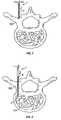
- FIG. 1shows of an initial phase of insertion of a stylet into an implant site
- FIG. 2shows the stylet having penetrated the cortical bone and approaching cancellous bone
- FIG. 3shows the stylet having reached the desired site of implantation
- FIG. 4shows the positioning of a cannula by guiding it along the stylet
- FIG. 5shows the cannula in position at the desired site of implantation, with the stylet still in position
- FIG. 6shows a stage after the stylet has been removed and a high pressure applicator has been mounted to the cannula
- FIG. 7shows the high pressure applicator used in FIG. 6 ;
- FIG. 8shows an alternative embodiment of a high pressure applicator according to the present invention.
- FIG. 9shows another embodiment of a high pressure applicator according to the present invention.
- FIG. 10shows an embodiment of a pressure applicator according to the present invention in which a portion of the column 74 has been cut away to show the relationship between the column or shaft 76 and column 74 ;
- FIG. 11shows a variation of the pressure applicator in FIG. 10 in which a portion of the column 74 ′ has been cut away to show the relationship between the column or shaft 76 ′ and column 74 ′;
- FIG. 12Ashows the column 74 ′ in FIG. 11 with an opening formed by removal of a hinged or removable section
- FIG. 12Bshows the removable section 82 of column 74 ′;
- FIG. 12Cshows the removable section taken along section line 12 C- 12 C in FIG. 12B .
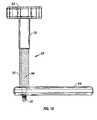
- FIG. 13shows another embodiment of a pressure applicator according to the present invention.
- FIG. 14shows still another embodiment of a pressure applicator according to the present invention.
- FIG. 15shows a high pressure applicator after being loaded with a hard tissue implant material and assembled
- FIG. 16shows an alternative embodiment of the high pressure applicator in FIG. 6 ;
- FIG. 17shows the high pressure applicator used in FIG. 16 ;
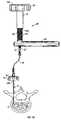
- FIG. 18shows an arrangement for high pressure, substantially noncompliant delivery of an implant material
- FIG. 19shows a cannula and two types of stylets useable with the present invention and indicates the manner in which they are assembled;
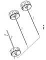
- FIG. 20shows a high pressure applicator having an enlarged introduction section, a substantially noncompliant tubing, a cannula and a stylet for use in performing a percutaneous implantation;
- FIG. 21shows the first column and a portion of the handle of the high pressure applicator in FIG. 20 ;
- FIG. 22shows alternate configurations of an end of the first column and an independent funnel useable with each
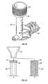
- FIG. 23Ashows a partially cut away view of a housing member, retainer member and plunger
- FIG. 23Bshows an end view of FIG. 23A ;
- FIG. 23Cis a sectional view of FIG. 23A showing the engagement of the plunger with the housing member.
- the present inventionsubstantially improves the delivery of hard tissue implant sites to the targeted zone of implantation, and is especially well suited for percutaneous deliveries.
- the present inventionsubstantially reduces several of the risk factors associated with the performance of percutaneous vertebroplasty. Additionally, the present invention enables an increase in an upper acceptable viscosity value of the implant to be delivered because of the increase in the amount of pressure available for controllably driving the delivery.
- FIGS. 1-6An example of a procedure for performing percutaneous vertebroplasty is illustrated in FIGS. 1-6 .
- FIG. 1An example of a procedure for performing percutaneous vertebroplasty is illustrated in FIGS. 1-6 .
- FIG. 1An example of a procedure for performing percutaneous vertebroplasty is illustrated in FIGS. 1-6 .
- FIG. 1An example of a procedure for performing percutaneous vertebroplasty is illustrated in FIGS. 1-6 .
- FIG. 1An example of a procedure for performing percutaneous vertebroplasty is illustrated in FIGS. 1-6 .
- FIGS. 1-6An example of a procedure for performing percutaneous vertebroplasty is illustrated in FIGS. 1-6 .
- FIGS. 1-6An example of a procedure for performing percutaneous vertebroplasty is illustrated in FIGS. 1-6 .
- FIGS. 1-6An example of a procedure for performing percutaneous vertebroplasty is illustrated in FIGS. 1-6 .
- 08/950,832 and 08/949,839are hereby incorporated by reference in their entireties.
- a currently preferred stylet 1 ′ and cannula 10 ′, and an optional direction guiding stylet 1 ′′are shown in FIG. 19 .
- a detailed description of these devices and their usesare disclosed in a co-owned application filed concurrently herewith, entitled “Precision Instruments for Use in Vertebroplasty”.
- the aforementioned application 09/409,948is hereby incorporated by reference in its entirety.
- a stylet 1which has a length that is more than sufficient to span the distance from the epidermis of a patient to the cancellous bone tissue in the vertebra, in the preferred configuration.
- the length of the styletwould be about three inches or greater, but lesser lengths may also be employed as well, depending on the size of the patient.
- the length of the styletcan be readily modified without departing from the inventive features of the present invention.
- the stylet 1is preferably made of a surgical grade of stainless steel, but other known equivalent biocompatible metals and materials may be used for the same purpose. Ideally, the stylet, or at least a distal end thereof, will be radiopaque so that it can be monitored using fluoroscopy, CT or other imaging techniques during the procedure to help determine the depth and location of the penetration.
- a first or distal end of the stylet 1ends in a point 2 which is sharp and adapted to penetrate hard tissue when axially loaded. Extending from the tip 2 are self-tapping threads 4 .
- the self-tapping threads 4provide an advantage in that once the tip 2 has penetrated the cortical bone (e.g., see FIG. 2 ), the operator of the stylet can then proceed to advance the stylet by torquing the stylet, which engages the self-tapping threads 4 in the cortical bone 103 and begins to screw the stylet 1 into the cortical bone 103 .
- Rotation of the stylet 1is continued, to advance the stylet into the bone, while monitoring the advancement with some type of imaging technique, e.g., fluoroscopy or equivalent.
- some type of imaging techniquee.g., fluoroscopy or equivalent.
- actual fluoroscopic viewsare generally from a perspective other than that shown in the Figures.
- the Figuresdepict a transverse sectional view of the vertebra as the instruments enter the vertebral body.
- Advancementis continued until the tip 2 reaches the site at which it is desired to deliver the implant material. Usually this site is in the cancellous bone as shown in FIG. 3 , but could be anywhere within the bone where there is osteoporosis, or a fracture or other defect or trauma.
- a cannula 10is provided which includes an elongated tubular structure 11 to be positioned in the cancellous bone or other implantation site for delivery of PMMA or other bone implant material therein.
- the tubular structure 11 of the cannula 10is preferably made of a surgical grade of stainless steel, but may be made of known equivalent materials, similarly to the stylet 1 discussed above.
- at least a distal end of the tubular structureis radiopaque.
- the tubular structure 11has an inside diameter which is only slightly larger than the outside diameter of the stylet 1 , so that the cannula may effortlessly pass axially over the stylet, while at the same time being supported and guided by the stylet.
- a first or distal end 12 of the cannulais preferably (but not necessarily) beveled or tapered to ease the penetration of the cannula through the cutaneous and soft tissues, and especially through the hard tissues.
- connector 18Surrounding the second end of the tubular structure 11 (or 11 ′ in FIG. 19 ) is a connector 18 ( FIGS. 6 , 19 ) for linking the cannula 10 , 10 ′ with a pressure applicator according to the present invention, for supplying the PMMA or other implantable material that is to be injected via tubular structure 11 , 11 ′.
- connector 18is a Luer-lock type of connector, but other known connecting mechanisms may be successfully interchanged, e.g., a flat bottom threaded hole, a conventional threaded hole, a threads and locking nut arrangement, etc.
- the cannula 10is advanced over the stylet, until visualization of the process indicates that the end of the cannula 12 is substantially even with the tip of the stylet 2 , whereby it is confirmed that the cannula is properly positioned for delivery of the implant material.
- the cannula 10 ′ and stylet 1 ′are advanced together, which is currently the preferred method of insertion.
- the stylet 1is removed from the site, either by reverse rotation or by simply withdrawing it.
- the cannula 10is maintained in position to be readied for delivery of the implant material.
- a pressure applicator 50 according to the present inventionis next mounted to the connector 18 at the end of cannula 10 , as shown in FIG. 6 .
- the pressure applicator 50is provided with a fitting 52 which is designed to form a pressure tight connection with the connector 18 .
- the preferred type of connectionis a Luer-lock type connection, but alternative, equivalent types of connectors may be employed.
- the pressure applicatorfurther includes a first column 54 for receiving and containing implant material.
- the first column 54is open at one end 54 a for receiving the material.
- At the other end 54 b of the first columnis a much smaller opening or orifice which ends with the connector or transfer fitting 52 or into which the connector or transfer fitting is mounted or placed (e.g., by threading, bonding, or the like).
- a second column 56is provided for overfitting first column 54 and providing a pressure seal therewith.
- the second column 56has interior threads 58 as shown in phantom in the exploded view of FIG. 7 .
- the interior threads 58mate or engage with exterior threads 60 provided on the first column 54 .
- other equivalent types of drivable engaging arrangementse.g., a ratchet and pawl arrangement, interior threading arrangement in the first column, or other equivalent arrangements could be used in place of the mating threads, so long as adequate force is able to be generated and maintained between the two columns for providing the driving pressure for the implant material.
- Column 56is open at end 56 a for receiving the first column 54 therein. At the opposite end 56 b , column 56 is closed to enable a generation of pressure within the two columns as they are moved toward one another and column 56 passes over column 54 .
- at least one sealing element 57e.g., a square, round or other type of O-ring, grommet, wrap of material or the like
- the sealing element(s) 57may also be provided integrally with the column 55 , e.g., by flaring out the column material to provide an interference fit, or the like. Since implant materials to be used in the invention (e.g. PMMA) are often very viscous, a high pressure capacity ensures that even thicker or more viscous mixes of implant material may be driven by the applicator 50 .
- An advantageous implant material that may be used with the high pressure applicator of the present inventionis a PMMA bone cement including contrast agents and/or tracer particles. Aspects of such a material are described in U.S. patent application Ser. No. 08/950,256, “Enhanced Visibility Materials For Implantation In Hard Tissue” by Preissman, filed Oct. 14, 1997. Contrast radiographic powder or particles of any typical material and of a size between 0.5 ⁇ to 1000 ⁇ may be included.
- a separate “sealing” elementneed not necessarily be provided.
- the O-ring or grommet optionally providedis preferred since it can move on the plunger rotationally and thus even if the plunger is turning with the handle, the seal can move independently.
- a plunger element 55is provided to be slidably driven by the first column 56 into the second column 54 .
- At least one O-ring 57 or equivalent sealing mechanismis mounted near a first end 55 a of the plunger element 55 to provide a friction fit between the plunger element 55 and the interior wall of the first column 54 .
- the plunger element 57is “started” in the end 54 b of the column 54 , by inserting a small length of the plunger element 57 to an extent which is at least enough to seat the O-ring 57 with the inner wall of the column 54 .
- the second column 56is initially connected with the column 54 by mating the threads 58 and 60 .
- a handle 62is mounted on the column 56 to provide additional leverage for driving the column 56 with respect to column 54 .
- the handle 62is provided at the closed end 56 b to provide a greater mechanical advantage for torquing column 56 about its longitudinal axis.
- the handlecould be provided anywhere along the column 56 so long as it extends the effective radius for torquing about the longitudinal axis.
- a handle 64is fixedly attached, molded, or otherwise mounted to the first column 54 . The handle 64 may be grasped by the operator and provides leverage against rotation of the first column 54 during driving of the second column 56 .
- the handle 64is in the form of a lever as shown in FIG. 6 , but alternative embodiments of the handle may include a circular handle, etc. so long as a sufficient mechanical advantage is provided to the user.
- a levermight extend from the column in an embodiment using a ratchet and pawl type of driving mechanism.
- the above described components of the pressure applicator 50are all preferably formed of amorphous nylon or ABS plastic, with at least column 54 being formed of clear or translucent amorphous nylon.
- any other materials which are durable, sterilizable, biofriendly and chemically compatible with the material to be implantede.g., stainless steel
- polycarbonateis not recommend for implanting PMMA, it may be fully acceptable for use in implanting other types of materials with which it has better chemical compatibility.
- the plunger element 55is shown as a separate component in the embodiment of FIG. 7 , it is noted that this element may be integrally formed with the column 56 ′, as shown in the embodiment of FIG. 8 , to form an extension 56 c ′ of the second column 56 ′.
- the extension 56 c ′is integrally formed or affixed to the closed end 56 b ′ of the column 56 ′ and extends the length thereof to emerge from the open end and extend therefrom to allow the sealing end and sealing element 57 to be inserted into the column 54 , prior to starting the interengagement of threads 58 and 60 .
- threads 58are not indicated in phantom, or at all, in FIG.
- extension 56 c ′does not have to take the form of the plunger 55 , but may have a much smaller cross section where it extends from the closed end.
- the extension 56 c ′may be formed as a much smaller rod with a first end having the same dimensions as that shown in FIG. 8 , to provide a proper seal with the column 54 .
- FIG. 9shows another embodiment of a pressure applicator 50 ′′ according to the present application.
- Pressure applicator 50 ′′is provided with a plunger element 55 ′′ which includes sealing element 57 and frictional element 59 , both preferably O-rings, at opposite ends thereof.
- the sealing and frictional arrangementsare not limited to the placement of one O-ring or equivalent but may use two or another multiple of sealing elements.
- Frictional element 59is provided to form a friction fit inside the closed end 56 b ′′ of the column 56 ′′.
- the plunger element 55 ′′is inserted into the column 56 ′′ initially until the end 55 b ′′ bottoms out against the closed end 56 b ′′ and the frictional element 59 forms a friction fit with the inner wall of the column 56 ′′ adjacent the closed end 56 b ′′.
- the friction fitis sufficient to maintain the plunger element 55 ′′ in position within the column 56 ′′ even when the column is held vertically, by the handle 62 , with the open end 56 a ′′ pointing downward.
- the friction fit between sealing element 57 and column 54in combination with the friction fit between the sealing element 59 and column 56 ′′ act to prevent rotation of the plunger element with respect to the column 54 as the plunger element is advanced into the column by the driving force of the column 56 ′′.
- the frictional forces between the sealing element 57 and the column 54are greater than those between the sealing element 59 and the column 56 ′′ so that the sealing element 59 slips against the inner wall of the column 56 ′′ as the column 56 ′′ is torqued to advance both the column 56 ′′ and the plunger element 55 ′′ with respect to the column 54 .
- the rotational movement of the closed end 56 b ′′ of the column 56 ′′is converted to a solely translational force against driving the plunger element 55 ′′.
- This featureis particularly important when the implant material comprises PMMA, as PMMA is somewhat abrasive if the plunger element 55 ′′ and sealing element 57 are allowed to rotate or are driven to, rotate with respect to the column 54 , this may allow some of the PMMA to work its way between a portion or all of the sealing element 57 and inner wall of the column 54 where it can act as an abrasive to prematurely degrade the sealing element 57 and/or the wall of the column 54 .
- the end 55 b ′′ and sealing element 59 as shownhave dimensions slightly larger than those of the end 55 a ′′ and sealing element 57 to account for the slightly larger inside diameter of the column 56 ′′ relative to the inside diameter of the column 54 . However, it is not necessary to use these dimensions, since a recess (not shown) having a smaller diameter can be formed (by boring, molding or otherwise) into the closed end 56 b ′′ so that a smaller end 55 b ′′ and sealing element 59 can be employed to form a friction fit therewith.
- FIGS. 23A-23CAnother variant of a frictional element useable to prevent rotation of the plunger or rod upon actuation of the applicator is pictured in FIGS. 23A-23C .
- the enlarged base 55 b ′′′ of the piston/plunger rod 55 ′′′includes and end 55 d having a spherical surface which is free to rotate with respect to the inner end surface 56 d of the second column 56 .
- the enlarged base 55 b ′′′is held ill position by the placement of one or more (preferably two) internal retaining rings 59 which engage within a recess in second column 56 and abut the enlarged base 55 b ′′′ to substantially prevent translational movement thereof with respect to the second column 56 .
- the rod 55 ′′′will not fall out of the second column 56 when inverted or otherwise jostled, but the rod 55 ′′′ is still allowed to turn relative to the column 56 .
- FIG. 10is a partial sectional view of an embodiment of a pressure applicator 70 , according to the present invention, in which a portion of the column 74 has been cut away to show the relationship between the column or shaft 76 and column 74 .
- column 74is interiorly threaded with threads 71 which mate with threads 78 on the exterior of column 76 .
- a sealing element 77e.g., an O-ring, Teflon wrap (formed by wrapping with Teflon tape, for example) or other equivalent
- a handleis also preferably mounted to the column 74 (e.g., similar to the handle 64 described above or to handles described below) to assist the user in developing the torque needed to generate high pressures.
- a handle 72is mounted to column 76 to further assist in generating torque.
- FIG. 11is a partial sectional view of a variation of an embodiment of a pressure applicator 70 ′, according to the present invention, in which a portion of the column 74 ′ has been cut away to show the relationship between the column or shaft 76 ′ and column 74 ′.
- the threads 71 ′are radially inset from the remainder of the inner wall 73 ′ of column 74 ′ which is left smooth.
- Threads 78 ′are exteriorly provided on column or shaft 76 ′ which mate with threads 71 ′.
- the distal end of shaft 76 ′is provided with an enlarged portion 79 which closely approximates or mates with the smooth inner wall 73 ′.
- a sealing element 77 ′(e.g., an O-ring, Teflon tape or other equivalent) may be mounted at or near the end of the enlarged portion 79 to enhance the pressure seal between the columns 76 ′ and 74 ′.
- a handle 75is also preferably mounted to the column 74 ′ to assist the user in developing the torque needed to generate high pressures. Although handle 75 is shown mounted to the proximal end of the column 74 ′, it is noted that the handle may also be mounted to the distal end, similar to that described with respect to handle 64 above, or at virtually any location along the length of the column that may be desirable, and still achieve the advantages of enhancing torque generation.
- the handle 75may be molded or otherwise formed integrally with the column 74 ′ or, alternatively, may be fixedly mounted to the column 74 ′ (e.g., by bonding, welding, splined or other mechanical arrangement) to provide torque to the column 74 ′ without slipping with respect thereto.
- a handle 72is mounted to column 76 ′ to further assist in generating torque.
- Section 82includes a hinge pin 84 which is insertable into a recess 86 in the wall of the remainder of the column 74 ′ for pivoting therewith, or allowing removal of the section altogether.
- Other types of hinges or movable attachmentsmay be readily substituted for the hinge pin 84 and recess 86 as would be apparent to those of ordinary skill in the art.
- One or preferably both edges of the section 82may be provided with flanges 88 or similar extensions to provide a snap or friction fit with the remainder of the column 74 ′ when the section 82 is installed. Further optionally, the inner wall of the remainder of the column may be provided with a recess or groove 87 to receive the flange or extension 88 to provide a more secure interlock. Additionally or alternatively, the column 74 ′ may be provided with a clamp or tying band (not shown) to surround the section 82 and column 74 ′ and compress the two pieces slightly to maintain them in a secure relationship.
- Insertion of the column 76 ′is performed by first removing or swinging open the section 82 away from the remainder of the column 74 ′.
- the proximal portion 76 a ′ of the column 76 ′has a smaller outside diameter than the threaded portion 78 ′ and is also sufficiently smaller than the inside diameter of the threads 71 ′, so that the enlarged portion 79 can be placed in the space 89 while the proximal portion 76 a ′ clears the threads 71 ′.
- the section 82is then replaced by snapping and/or clamping the same into position against the remainder of the column 74 ′, thereby surrounding the proximal portion 76 a ′ and enlarged portion 79 .
- Threads 78 ′can then be started with threads 71 ′ to ready the applicator 70 ′ for application of a pressurized driving force.
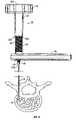
- FIG. 13is a plan view of another embodiment of a pressure applicator 90 according to the present invention.
- Column 94is configured and dimensioned to receive a disposable syringe 150 (shown in phantom lines) therein.
- this embodimentcan be used with a 10 cc syringe, thereby enabling much greater pressures to be generated than discussed above.
- the column 94can be formed as a two stage column, as shown, having a first inside diameter 94 c which is smaller than a second inside diameter 94 d . This design allows the barrel 152 of the syringe 150 to be received in the portion 94 c and abut against a tapered portion of the column 94 e .
- a transition collar 94 fwhich interconnects the varying diameter portions 94 c and 94 d of the column 94 , provides a surface against which the flange or “wings” of the syringe barrel 152 abut.
- An alternative arrangementcould have a column having a single stage or inner diameter which could rely on the tapered region 94 e solely for abutment of the syringe barrel 152 .
- the syringe plunger 154is received in the larger diameter portion 94 d of the column 94 (which, in the alternative arrangement described would be the single stage or diameter).
- a second column or shaft 96is externally threaded and external threads are designed to mate with internal threads (not shown) on the interior wall of the column portion 94 d .
- the distal end 96 a of column 96abuts against the end 158 of the syringe plunger 154 upon threading the column 96 into column 94 . Further torquing of the handle 92 with respect to the column 94 generates a driving force for translationally advancing the syringe plunger 154 to generate a high pressure driving force.
- a sealing element(not shown) is preferably mounted at or near the distal end of the syringe plunger 154 , as is known in the art, to enhance the pressure generation.
- a handleis also preferably mounted to the column 94 (e.g., similar to the handle 64 or 75 described above) to assist the user ill developing the torque needed to generate high pressures.
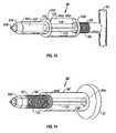
- FIG. 14is a plan view of another embodiment of a pressure applicator 90 ′ according to the present invention.
- Column 94 ′is configured and dimensioned to receive a disposable syringe 150 (shown in phantom lines) therein.
- the column 94 ′can be formed as a two stage column, similar to that described above with regard to FIG. 13 , but is formed as a single stage or single diameter column in FIG. 14 . This design allows the barrel 152 of the syringe 150 to be received in the column 94 ′ and abut against a tapered portion of the column 94 e ′.
- the syringe plunger 154extends from the proximal opening 94 a ′ of the column 94 and is received in the column 96 ′.
- Column 96 ′is internally threaded (threads not shown) and the internal threads are designed to mate with external threads 93 on column 94 ′.
- the closed proximal end 96 a ) of column 96 ′abuts against the end 158 of the syringe plunger 154 upon receiving the plunger 154 in column 96 ′ and beginning mating of the internal threads of the column 96 ′ with threads 93 .
- a sealing element(not shown) is preferably mounted at or near the distal end of the syringe plunger 154 , as is known in the art, to enhance the pressure generation.
- a handleis also preferably mounted to the column 94 , (e.g., similar to the handle 64 or 75 described above) to assist the user in developing the torque needed to generate high pressures.
- a tissue implant materialin this example, a hard tissue implant material 66 is loaded into the first column 54 and the second column 56 is connected with the first column 54 in preparation for implantation, see FIG. 15 .
- the pressure applicator 50is shown in FIGS. 6 , 15 and 18 , it is noted that the principles described with respect thereto are generally applicable to each of the embodiments described herein. Of course, minor variations in procedure may be necessary, e.g., loading the syringe 150 with implant material, rather than the pressure applicator column, when using the embodiments of FIGS. 13 and 14 , etc., but the general principles described herein may be applied to any embodiment by those of ordinary skill in the art.
- a tissue implant material 66is loaded into the first column 54 and the second column 56 is connected with the first column 54 in preparation for implantation.
- the introduction of air bubblescan be further substantially reduced or avoided by slightly overfilling the firs column to form a meniscus created by surface tension of the implant material and then introducing the plunger element into the material and driving the plunger into the first column.
- This optional techniquemay be used in all of the disclosed embodiments, but may be obviated by the features shown in the embodiments of FIGS. 20-22 , as discussed below.
- the first columnis then rotated slightly with respect to the second column until a minimal amount of tissue implant material is expressed from the fitting 52 end, to ensure that no air has been entrapped in the applicator.
- the cannula 10is backfilled with saline, tissue implant material 66 , or other biocompatible fluid in order to displace the air therefrom.
- the pressure applicator 50is then mounted onto the cannula 10 as described above and shown in FIG. 6 .
- the operatornext grasps the handle 62 in one hand and the handle 64 in the other and begins to torque the handle 62 while maintaining the handle 64 in its position.
- the pressure applicatoris capable of generating pressures of about 1000 to 3000 psi within the columns, which is a high driving force that is applied to the implantable material 66 .
- Torquing of the handle 62 with respect to the handle 64is continued until a sufficient amount of implant material 66 has been delivered to the implant site as verified by an appropriate imaging technique.
- endpointing techniquesare described in the application Ser. No. 09/409,948 entitled “Precision Instruments for Use in Vertebroplasty”, which was incorporated by reference above.
- the pressure applicator 50allows a first column 54 which is large enough in volume at least 5 cc, preferably at least 7.5 cc, and more preferably at least 10 cc and up to about 15 cc to contain sufficient implant material for an entire implantation process so that there is no need to refill the column 54 in the midst of a procedure.
- the designs disclosed hereincould be enlarged so as to have a capacity up to 25 cc and even upwards of 30 cc. It would further be apparent to those of ordinary skill in the art to modify the designs herein to have capacities even larger than that disclosed should an implantation procedure require larger volumes of material.
- cannula 10 ′includes a modified tubular structure design.
- the first or distal portion 11 a of the tubular structureis of the same dimensions as the embodiment of FIGS. 1-6 .
- the second or proximal portion 11 b of the cannula 10 ′has a substantially larger diameter than that of the first portion 11 a .
- the diameter of second portion 11 bis about twice the diameter of the first portion 11 a , although any increase in the diameter of the second portion 11 b over that of the first portion 11 a will decrease the pressure requirement for effective delivery of the material to be implanted.
- the first and second portions 11 a , 11 bhave approximately equal lengths, but this is governed by the anatomy of the site to be accessed. In the “average” percutaneous vertebroplasty situation, the first portion 11 a is required to be about 1.5′′ long, as this is the length that is needed for traversing the cortical bone of the pedicle. Thus, the first portion should not be significantly enlarged due to the size constraints of the pedicle, the safety risks to the spinal column and aorta which are increased when the cannula size is increased intravertebrally, and by the desire to remove as little bone as possible when entering with the stylet and cannula, among other factors.
- the portion of the cannula which will occupy the soft tissuescan be significantly expanded without substantially adversely effecting the patient. Given the benefits of reducing the required injection pressure and ensuring a better delivery of the bone implant material, such a modification becomes a viable option.
- the pressure applicator 50 ′′′is essentially the same as that in the embodiment 50 , with modifications as follows.
- the pressure applicator 50 ′′′is provided with a fitting 52 ′′′ ( FIG. 17 ) which is designed to form a pressure tight connection with the connector 18 ′ and is therefore of a significantly larger diameter than the connector 52 .
- the first column 54 ′is essentially open at both ends 54 a ′′′ and 54 b ′′′ as it does not taper or tapers much less than the previous embodiment at opening 54 b ′′′.
- the preferred type of connectionis a Luer-lock type connection, but alternative, equivalent types of connectors may be employed.
- the components of the pressure applicator 50 ′′′are all preferably formed of amorphous nylon.
- the housing or second column or any portions which do not contact the implant materialmay be formed of ABS plastic. Additionally, any other materials which are durable, sterilizable, biofriendly and nonreactive with the particular implant materials to be contained therein, e.g., stainless steel, polypropylene, could be readily substituted.
- a hard tissue implant material 66is loaded into the first column 54 and the second column 56 is connected with the first column 54 in preparation for implantation.
- the pressure applicator 50 ′is then mounted onto the cannula 10 ′ as shown in FIG. 16 .
- the operatornext grasps the handle 62 in one hand and the handle 64 in the other and begins to torque the handle 62 .
- the pressure applicatoris capable of generating controllable and sustainable pressures of up to about 3000 psi within the columns, which is a high driving force that is applied to the implantable material 66 .
- a high pressure tubing 70may be and preferably is interconnected between the pressure applicator 50 and the cannula 10 , as shown in FIG. 18 .
- the tubingbe a substantially non-compliant tubing, to obviate problems of “oozing” and overfilling that occur when there is too much compliance in a high pressure implantation system.
- high pressure, substantially non-compliant tubingsinclude PEEK tubing, and other polymers such as Nylon, PTFE, and FEP which may be radially reinforced with a no-stretch coil such as a flat wire spring of stainless steel, aramid fibers such as Kevlar, etc.
- a no-stretch coilsuch as a flat wire spring of stainless steel, aramid fibers such as Kevlar, etc.
- the tubing 70has mate 72 and female 74 connectors for forming pressure tight seals with, fitting 52 and connector 18 , respectively.
- the tubing 70enables both the applicator 50 , and thus the user's hands to be distanced from the radiographic field or other viewing field, which is advantageous both for safety purposes as well as improving the procedure.
- This embodimentis particularly advantageous for the most frequent set-ups where bi-planar viewing is performed and two imaging devices are oriented at 90° to one another about the implantation site.
- One of the advantages which is gained that improves the procedure,is that the viewing instrumentation can be moved closer to the actual implantation site, thereby providing a more magnified view.
- the tubing 70is mounted to the pressure applicator prior to mounting on the cannula fitting 13 . After filling the pressure applicator with implant material as described above, the tubing 70 is mounted to fitting 52 . A small amount of pressure is next applied to the implant material to express the implant material until a minimal amount exits the open end of the tubing (i.e., the end where connector 74 is located). The tubing 70 is then connected to the connector 18 of the cannula 10 for implantation of the implant material into the desired location.
- the foregoingis the desired order of connection so that the air space in the tubing can be prefilled with implant material, it is not the only possible progression for the procedure.
- the tubing 70can be connected to the fitting 13 of the cannula 10 and the tubing 70 and cannula 10 are then backfilled with saline, implant material, or other biocompatible fluid to displace any air residing in the structures.
- the tubingcan be connected to the fitting 52 and implantation of the implant material can be rapidly commenced thereafter.
- FIG. 20shows a high pressure applicator having an enlarged introduction section, a substantially noncompliant tubing, a cannula and a stylet for use in performing a percutaneous implantation.
- High pressure applicator having the feature of an enlarged introduction sectionare further disclosed and claimed in a co-owned application filed concurrently herewith, entitled “High Pressure Delivery System”.
- the application Ser. No. 11/369,662 filed concurrently herewith entitled “High Pressure Delivery System”is hereby incorporated by reference thereto in its entirety.
- FIG. 21is an enlarged detail showing of the first column 30 and a portion of the handle 40 of the high pressure applicator shown in FIG. 20 .
- the open end portion of the first column 30is formed as an introduction section 24 which has a slightly larger cross-sectional area than that of the portion of the first column 30 adjacent to it. Providing a larger size or diameter introduction section 24 enables the introduction of the plunger 44 into the implant material without simultaneously forming a seal where compliant bubbles may be trapped.
- the differential in sizesis provided so that when the smaller diameter portion of the first column 30 is fully filled and the introduction section 24 is at least partially filled, the end of the plunger 44 which might otherwise trap air bubbles resulting in system compliance will be dipped in the implant material thereby allowing for the exclusion of air bubbles prior to driving it into the smaller diameter portion.
- the introduction section 24may be relatively close in size to the adjoining smaller diameter portion to provide only a surrounding dam for a meniscus poured over the smaller diameter portion. Since the amount of material that needs to be provided in the introduction section need not be great to facilitate the venting or purging as described above, it is better to only introduce slightly more implant material than will fill the smaller diameter portion. Introduction of a larger amount of implant material is not only wasteful, but may result in material drainage out of the introduction section into other parts of the applicator—especially when the applicator is inverted or turned as will often be the case in preparing PMMA implant material for delivery.
- a larger size of the introduction section 24 than strictly required for the venting feature discussed abovemay be used to act as a catch basin for excess material. This will provide a larger margin of error in pouring implant material into the applicator before overflowing the introduction section 24 will occur. Further, the walls of such an enlarged catch basin may help to prevent contamination of the applicator by virtue of adherence of the implant material to the surface area provided during inversion or agitation of the applicator.
- the introduction sectionis provided with threads 32 which engage with threads (not shown) on the interior of the second column 36 , similar to the arrangements provided in the embodiments shown in FIGS. 6-9 .
- Handle 38is provided for torquing the second column 36 with respect to the first column 30 .
- the concept of the introduction sectioncould be applied to any of those embodiments, and could also be adapted to the embodiments having threading internally of an introduction section with external threading on a second column.
- the conceptis also generally applicable to the embodiments shown in FIGS. 13 and 14 , where an introduction section could be provided in the barrel 152 of the syringe.
- FIG. 22shows alternate configurations of an end of the first column 30 ′ and 30 ′′, and an independent funnel 54 useable with each.
- the funnel or increased-size target region 54may also be integrated into the introduction section 24 to aid in pouring implant material into the applicator.
- Drive threadsmay be placed on the exterior funnel 54 .
- a presently preferred thread sizeis 11 ⁇ 2-12 ACME 2.G 10° external.
- a smaller introduction section 24 ′, 24 ′′may be used to provide a greater mechanical advantage.
- the drive threads placed exterior theretomay be of a finer pitch or higher thread count than those previously described to provide for greater mechanical advantage for generating higher driving pressures more easily.
- a separate funnel element 54may be provided to interface with the introduction section 24 .
- the first columnis advantageously about 0.50 inches in diameter and of a length of about 4 inches in order to provide sufficient volume for implant material for efficiency in performing vertebroplasty and yet have a small enough bore so that the mechanical advantage in applying pressure to the implant material is not overly affected as would be the case with a much larger bore.
- the preferred size range for the first columnis between about 0.375 to about 0.75 inches with a length of between about 1.5 and 4.5 inches.
- the preferred capacitance of the first columnis at least 5 cc, up to about 15 cc, as described above.
Landscapes
- Health & Medical Sciences (AREA)
- Orthopedic Medicine & Surgery (AREA)
- Life Sciences & Earth Sciences (AREA)
- Surgery (AREA)
- Animal Behavior & Ethology (AREA)
- Veterinary Medicine (AREA)
- Public Health (AREA)
- Engineering & Computer Science (AREA)
- Biomedical Technology (AREA)
- Heart & Thoracic Surgery (AREA)
- General Health & Medical Sciences (AREA)
- Nuclear Medicine, Radiotherapy & Molecular Imaging (AREA)
- Medical Informatics (AREA)
- Molecular Biology (AREA)
- Transplantation (AREA)
- Vascular Medicine (AREA)
- Oral & Maxillofacial Surgery (AREA)
- Cardiology (AREA)
- Physical Education & Sports Medicine (AREA)
- Prostheses (AREA)
Abstract
Description
Claims (18)
Priority Applications (1)
| Application Number | Priority Date | Filing Date | Title |
|---|---|---|---|
| US10/301,454US7572263B2 (en) | 1998-04-01 | 2002-11-20 | High pressure applicator |
Applications Claiming Priority (4)
| Application Number | Priority Date | Filing Date | Title |
|---|---|---|---|
| US5310898A | 1998-04-01 | 1998-04-01 | |
| US09/409,934US6383190B1 (en) | 1998-04-01 | 1999-09-30 | High pressure applicator |
| US10/039,892US20040215202A1 (en) | 1998-04-01 | 2001-10-26 | High pressure applicator |
| US10/301,454US7572263B2 (en) | 1998-04-01 | 2002-11-20 | High pressure applicator |
Related Parent Applications (1)
| Application Number | Title | Priority Date | Filing Date |
|---|---|---|---|
| US10/039,892ContinuationUS20040215202A1 (en) | 1998-04-01 | 2001-10-26 | High pressure applicator |
Publications (2)
| Publication Number | Publication Date |
|---|---|
| US20030078589A1 US20030078589A1 (en) | 2003-04-24 |
| US7572263B2true US7572263B2 (en) | 2009-08-11 |
Family
ID=33302413
Family Applications (1)
| Application Number | Title | Priority Date | Filing Date |
|---|---|---|---|
| US10/301,454Expired - Fee RelatedUS7572263B2 (en) | 1998-04-01 | 2002-11-20 | High pressure applicator |
Country Status (1)
| Country | Link |
|---|---|
| US (1) | US7572263B2 (en) |
Cited By (51)
| Publication number | Priority date | Publication date | Assignee | Title |
|---|---|---|---|---|
| US20050113736A1 (en)* | 2003-11-26 | 2005-05-26 | Orr Keith M. | Arthroscopic tissue scaffold delivery device |
| US20050113843A1 (en)* | 2003-11-25 | 2005-05-26 | Arramon Yves P. | Remotely actuated system for bone cement delivery |
| US20060142779A1 (en)* | 2004-12-23 | 2006-06-29 | Arthrocare Corporation | Cannula having asymmetrically-shaped threads |
| US20060266372A1 (en)* | 1999-09-30 | 2006-11-30 | Arthrocare Corporation | High pressure delivery system |
| US20070043376A1 (en)* | 2003-02-21 | 2007-02-22 | Osteobiologics, Inc. | Bone and cartilage implant delivery device |
| US20070191858A1 (en)* | 2005-09-01 | 2007-08-16 | Csaba Truckai | Systems for delivering bone fill material |
| US20080154304A1 (en)* | 2006-12-21 | 2008-06-26 | Arthrocare Corporation | System and method for accessing a tissue structure |
| US20080172058A1 (en)* | 2007-01-12 | 2008-07-17 | Warsaw Orthopedic, Inc. | System and Method for Pressure Mixing Bone Filling Material |
| US20080172127A1 (en)* | 2007-01-16 | 2008-07-17 | Mi4Spine, Llc | Minimally Invasive Interbody Device |
| US20090093818A1 (en)* | 2006-04-07 | 2009-04-09 | Societe De Commercialisation Des Produits De La Recherche Appliquee Socpra Sciences Et Genie S.E.C | Intergrated cement delivery system for bone augmentation procedures and methods |
| US20090099410A1 (en)* | 2005-06-09 | 2009-04-16 | De Marchena Eduardo | Papillary Muscle Attachment for Left Ventricular Reduction |
| US20100023065A1 (en)* | 2008-07-25 | 2010-01-28 | Welch Andrea M | Tissue access device with alignment guide and methods of use |
| US20100114174A1 (en)* | 2008-10-30 | 2010-05-06 | Bryan Jones | Systems and Methods for Delivering Bone Cement to a Bone Anchor |
| US20100204611A1 (en)* | 2009-02-06 | 2010-08-12 | Roberto Zambelli | Bone biopsy device |
| US20100286616A1 (en)* | 2009-05-05 | 2010-11-11 | Gamal Baroud | Cannula assembly with detachable inner and outer cannulas |
| US8066713B2 (en) | 2003-03-31 | 2011-11-29 | Depuy Spine, Inc. | Remotely-activated vertebroplasty injection device |
| US8109933B2 (en) | 2007-04-03 | 2012-02-07 | Dfine, Inc. | Bone treatment systems and methods |
| US8142462B2 (en) | 2004-05-28 | 2012-03-27 | Cavitech, Llc | Instruments and methods for reducing and stabilizing bone fractures |
| US8221420B2 (en) | 2009-02-16 | 2012-07-17 | Aoi Medical, Inc. | Trauma nail accumulator |
| US8353911B2 (en) | 2007-05-21 | 2013-01-15 | Aoi Medical, Inc. | Extendable cutting member |
| US8361078B2 (en) | 2003-06-17 | 2013-01-29 | Depuy Spine, Inc. | Methods, materials and apparatus for treating bone and other tissue |
| US8360629B2 (en) | 2005-11-22 | 2013-01-29 | Depuy Spine, Inc. | Mixing apparatus having central and planetary mixing elements |
| US8415407B2 (en) | 2004-03-21 | 2013-04-09 | Depuy Spine, Inc. | Methods, materials, and apparatus for treating bone and other tissue |
| US8579908B2 (en) | 2003-09-26 | 2013-11-12 | DePuy Synthes Products, LLC. | Device for delivering viscous material |
| US8827981B2 (en) | 2007-11-16 | 2014-09-09 | Osseon Llc | Steerable vertebroplasty system with cavity creation element |
| US8950929B2 (en) | 2006-10-19 | 2015-02-10 | DePuy Synthes Products, LLC | Fluid delivery system |
| US8992541B2 (en) | 2003-03-14 | 2015-03-31 | DePuy Synthes Products, LLC | Hydraulic device for the injection of bone cement in percutaneous vertebroplasty |
| US9095392B2 (en) | 2009-11-06 | 2015-08-04 | Gamal Baroud | Bone cement delivery system |
| US9119639B2 (en) | 2011-08-09 | 2015-09-01 | DePuy Synthes Products, Inc. | Articulated cavity creator |
| US9155580B2 (en) | 2011-08-25 | 2015-10-13 | Medos International Sarl | Multi-threaded cannulated bone anchors |
| US9241729B2 (en) | 2012-12-14 | 2016-01-26 | DePuy Synthes Products, Inc. | Device to aid in the deployment of a shape memory instrument |
| US9381024B2 (en) | 2005-07-31 | 2016-07-05 | DePuy Synthes Products, Inc. | Marked tools |
| US9439693B2 (en) | 2013-02-01 | 2016-09-13 | DePuy Synthes Products, Inc. | Steerable needle assembly for use in vertebral body augmentation |
| US9445918B1 (en) | 2012-10-22 | 2016-09-20 | Nuvasive, Inc. | Expandable spinal fusion implants and related instruments and methods |
| US9510885B2 (en) | 2007-11-16 | 2016-12-06 | Osseon Llc | Steerable and curvable cavity creation system |
| US9642932B2 (en) | 2006-09-14 | 2017-05-09 | DePuy Synthes Products, Inc. | Bone cement and methods of use thereof |
| US9867646B2 (en) | 2006-04-07 | 2018-01-16 | Gamal Baroud | Integrated cement delivery system for bone augmentation procedures and methods |
| US9918767B2 (en) | 2005-08-01 | 2018-03-20 | DePuy Synthes Products, Inc. | Temperature control system |
| EP3075354B1 (en) | 2011-05-05 | 2018-11-21 | Symetis SA | Method and apparatus for compressing/loading stent-valves |
| US10136934B2 (en) | 2005-08-22 | 2018-11-27 | Dfine, Inc. | Bone treatment systems and methods |
| US10463380B2 (en) | 2016-12-09 | 2019-11-05 | Dfine, Inc. | Medical devices for treating hard tissues and related methods |
| US10478241B2 (en) | 2016-10-27 | 2019-11-19 | Merit Medical Systems, Inc. | Articulating osteotome with cement delivery channel |
| US10624652B2 (en) | 2010-04-29 | 2020-04-21 | Dfine, Inc. | System for use in treatment of vertebral fractures |
| US10660656B2 (en) | 2017-01-06 | 2020-05-26 | Dfine, Inc. | Osteotome with a distal portion for simultaneous advancement and articulation |
| US11026744B2 (en) | 2016-11-28 | 2021-06-08 | Dfine, Inc. | Tumor ablation devices and related methods |
| US11026734B2 (en) | 2004-12-06 | 2021-06-08 | Dfine, Inc. | Bone treatment systems and methods |
| USD937643S1 (en)* | 2020-07-22 | 2021-12-07 | Frank Vogel Llc | Dispensing syringe |
| US11197681B2 (en) | 2009-05-20 | 2021-12-14 | Merit Medical Systems, Inc. | Steerable curvable vertebroplasty drill |
| US11510723B2 (en) | 2018-11-08 | 2022-11-29 | Dfine, Inc. | Tumor ablation device and related systems and methods |
| US20230270436A1 (en)* | 2022-02-25 | 2023-08-31 | Life Spine, Inc. | Vertebral Disc Auger |
| US11986229B2 (en) | 2019-09-18 | 2024-05-21 | Merit Medical Systems, Inc. | Osteotome with inflatable portion and multiwire articulation |
Families Citing this family (27)
| Publication number | Priority date | Publication date | Assignee | Title |
|---|---|---|---|---|
| US6440138B1 (en)* | 1998-04-06 | 2002-08-27 | Kyphon Inc. | Structures and methods for creating cavities in interior body regions |
| WO2002013700A2 (en)* | 2000-08-11 | 2002-02-21 | Sdgi Holdings, Inc. | Surgical instrumentation and method for treatment of the spine |
| US8668698B2 (en) | 2002-05-31 | 2014-03-11 | Vidacare Corporation | Assembly for coupling powered driver with intraosseous device |
| US10973545B2 (en) | 2002-05-31 | 2021-04-13 | Teleflex Life Sciences Limited | Powered drivers, intraosseous devices and methods to access bone marrow |
| EP2039298B1 (en) | 2002-05-31 | 2017-10-25 | Vidacare LLC | Apparatus to access bone marrow |
| US8641715B2 (en) | 2002-05-31 | 2014-02-04 | Vidacare Corporation | Manual intraosseous device |
| US11337728B2 (en) | 2002-05-31 | 2022-05-24 | Teleflex Life Sciences Limited | Powered drivers, intraosseous devices and methods to access bone marrow |
| US9504477B2 (en) | 2003-05-30 | 2016-11-29 | Vidacare LLC | Powered driver |
| DE10339171A1 (en)* | 2003-08-22 | 2005-03-24 | Bizerba Gmbh & Co. Kg | Slicing machine |
| US7641664B2 (en)* | 2004-02-12 | 2010-01-05 | Warsaw Orthopedic, Inc. | Surgical instrumentation and method for treatment of a spinal structure |
| JP2008503275A (en)* | 2004-06-16 | 2008-02-07 | ウォーソー・オーソペディック・インコーポレーテッド | Surgical instruments and methods for treatment of spinal structures |
| JP2008539026A (en)* | 2005-04-29 | 2008-11-13 | ワイス | Drug delivery device and related components, systems, and methods |
| USD669168S1 (en) | 2005-11-18 | 2012-10-16 | Carefusion 2200, Inc. | Vertebral augmentation needle |
| US8690884B2 (en) | 2005-11-18 | 2014-04-08 | Carefusion 2200, Inc. | Multistate-curvature device and method for delivering a curable material into bone |
| US7799035B2 (en)* | 2005-11-18 | 2010-09-21 | Carefusion 2200, Inc. | Device, system and method for delivering a curable material into bone |
| US7713273B2 (en)* | 2005-11-18 | 2010-05-11 | Carefusion 2200, Inc. | Device, system and method for delivering a curable material into bone |
| US20070161962A1 (en)* | 2006-01-09 | 2007-07-12 | Edie Jason A | Device and method for moving fill material to an implant |
| US8361032B2 (en)* | 2006-02-22 | 2013-01-29 | Carefusion 2200 Inc. | Curable material delivery device with a rotatable supply section |
| US20100069786A1 (en)* | 2006-06-29 | 2010-03-18 | Depuy Spine, Inc. | Integrated bone biopsy and therapy apparatus |
| US20080045964A1 (en)* | 2006-08-16 | 2008-02-21 | Allan Mishra | Device for cartilage repair |
| MX2009002455A (en)* | 2006-09-07 | 2009-03-20 | Wyeth Corp | Bone cement mixing systems and related methods. |
| US8944069B2 (en) | 2006-09-12 | 2015-02-03 | Vidacare Corporation | Assemblies for coupling intraosseous (IO) devices to powered drivers |
| CA2928681C (en)* | 2007-08-29 | 2018-03-27 | Etex Corporation | Bone cement mixing and delivery system and methods of use thereof |
| US8277506B2 (en) | 2008-06-24 | 2012-10-02 | Carefusion 2200, Inc. | Method and structure for stabilizing a vertebral body |
| KR100950989B1 (en)* | 2008-07-03 | 2010-04-02 | (주)태연메디칼 | Device for transdermal delivery of bone filling material |
| US8894658B2 (en) | 2009-11-10 | 2014-11-25 | Carefusion 2200, Inc. | Apparatus and method for stylet-guided vertebral augmentation |
| US10098682B2 (en)* | 2014-06-16 | 2018-10-16 | Medtronic Holding Company Sárl | High pressure remote delivery system for cement and methods of use |
Citations (227)
| Publication number | Priority date | Publication date | Assignee | Title |
|---|---|---|---|---|
| US29083A (en) | 1860-07-10 | Benjamin irving | ||
| US115794A (en) | 1871-06-06 | Improvement in stop-valves | ||
| US951160A (en)* | 1908-10-16 | 1910-03-08 | John W Wainwright | Syringe. |
| US1128092A (en) | 1914-05-29 | 1915-02-09 | Ross J Barrett | Valve. |
| US1142210A (en) | 1912-02-29 | 1915-06-08 | Rayvio Water Company | Liquid-dispensing device. |
| US1328567A (en)* | 1919-07-23 | 1920-01-20 | Jones Edmund Vaughan | Apparatus for injecting fluids and semisolids |
| US1709691A (en)* | 1924-09-22 | 1929-04-16 | Cook Lab Inc | Hypodermic syringe |
| US2002610A (en) | 1931-09-18 | 1935-05-28 | Elmer L Nall | Fluid dispensing device |
| US2102591A (en)* | 1935-06-05 | 1937-12-21 | Hagemeier Heinrich | Dental syringe |
| US2176042A (en) | 1936-06-25 | 1939-10-10 | Sharp & Dohme Inc | Container for lyophilic biologically active substances |
| US2420102A (en) | 1945-07-27 | 1947-05-06 | Roy W Hunting | Syringe extension |
| US2426535A (en) | 1944-10-21 | 1947-08-26 | Turkel Henry | Infusion and biopsy needle |
| US2573547A (en) | 1946-04-10 | 1951-10-30 | White S Dental Mfg Co | Amalgam carrier |
| US2676475A (en) | 1951-10-12 | 1954-04-27 | Ronson Art Metal Works Inc | Cigar lighter structure |
| US2919692A (en) | 1956-02-23 | 1960-01-05 | Ackermann Wolfgang | Vertebral trephine biopsy instruments |
| US2973758A (en) | 1956-12-27 | 1961-03-07 | Invenex Pharmaceuticals | Apparatus for manufacturing parenteral solutions |
| US3384274A (en)* | 1966-06-07 | 1968-05-21 | Kenneth W. Lundvall | Ultrahigh pressure grease gun |
| US3581399A (en) | 1969-08-08 | 1971-06-01 | Centrix Inc | Composite resin filling syringe and technique |
| US3701771A (en) | 1969-06-27 | 1972-10-31 | Nyegaard & Co As | N-(2,4,6-triiodobenzoyl)-sugar amines |
| US3750667A (en) | 1972-01-31 | 1973-08-07 | N Pshenichny | Device for intraosseous injection of liquid substances |
| US3809297A (en)* | 1972-06-21 | 1974-05-07 | Poulten J Ltd | Piston and cylinder device |
| US3835860A (en) | 1973-06-21 | 1974-09-17 | H Garretson | Surgical bone punch |
| US3882858A (en) | 1973-04-21 | 1975-05-13 | Merck Patent Gmbh | Surgical synthetic-resin material and method of treating osteomyelitis |
| US3900954A (en) | 1974-07-10 | 1975-08-26 | William B Dragan | Dental filling gun and nozzle tip therefor |
| US3919773A (en) | 1973-12-20 | 1975-11-18 | Sybron Corp | Direct moldable implant material |
| US3929708A (en) | 1974-08-15 | 1975-12-30 | Phillips Petroleum Co | Arylene sulfide polymers comprising silicone fluids |
| US3993065A (en) | 1975-05-20 | 1976-11-23 | Szabo Anthony W | Fluid infusion apparatus |
| US4011685A (en) | 1974-06-24 | 1977-03-15 | Boyd William A | Plant injection method and apparatus |
| US4011869A (en) | 1975-08-01 | 1977-03-15 | David Kopf Instruments | Tubular cutting instrument |
| US4032118A (en) | 1975-10-21 | 1977-06-28 | Phillips Edwin D | Sealing means for stirring apparatus |
| GB1488975A (en) | 1974-03-29 | 1977-10-19 | Muanyagipari Kutato Intezet | Flexible hose of high pressure-bearing capability and process for the production thereof |
| US4079518A (en) | 1976-07-01 | 1978-03-21 | Odyssey Corporation For Research And Development | Amalgam mixing, mulling and dispensing syringe |
| US4091812A (en) | 1976-01-19 | 1978-05-30 | Alcon Laboratories, Inc. | Operator means for syringe cartridges |
| US4099518A (en) | 1976-05-10 | 1978-07-11 | Baylis Shelby M | Biopsy apparatus |
| US4155969A (en) | 1975-09-02 | 1979-05-22 | Ex-Cell-O Corporation | Method for injection foam molding |
| US4184490A (en)* | 1978-08-23 | 1980-01-22 | John Jacklich | Precision endodontic syringe |
| US4189065A (en) | 1976-02-04 | 1980-02-19 | Espe Fabrik Pharmazeutischer Praeparate Gmbh | Metering dispenser for high-viscosity compositions |
| US4232670A (en) | 1978-06-30 | 1980-11-11 | Howmedica International, Inc. Zweigniederlassung | Tube type supply container for medical syringe |
| US4274163A (en) | 1979-07-16 | 1981-06-23 | The Regents Of The University Of California | Prosthetic fixation technique |
| US4288355A (en) | 1978-05-22 | 1981-09-08 | Minnesota Mining And Manufacturing Company | Surgical cement composition |
| US4312343A (en) | 1979-07-30 | 1982-01-26 | Leveen Harry H | Syringe |
| US4338925A (en)* | 1979-12-20 | 1982-07-13 | Jo Miller | Pressure injection of bone cement apparatus and method |
| US4341691A (en) | 1980-02-20 | 1982-07-27 | Zimmer, Inc. | Low viscosity bone cement |
| US4346708A (en)* | 1981-04-20 | 1982-08-31 | Leveen Harry H | Syringe |
| US4364921A (en) | 1979-03-08 | 1982-12-21 | Schering, Aktiengesellschaft | Novel triiodinated isophthalic acid diamides as nonionic X-ray contrast media |
| US4374093A (en) | 1981-02-20 | 1983-02-15 | Mobil Oil Corporation | Continuous-stream upflow zeolite crystallization apparatus |
| US4373217A (en) | 1979-02-16 | 1983-02-15 | Merck Patent Gesellschaft Mit Beschrankter Haftung | Implantation materials and a process for the production thereof |
| US4404327A (en) | 1979-10-31 | 1983-09-13 | Crugnola Aldo M | Orthopaedic cement from acrylate polymers |
| US4448188A (en) | 1982-02-18 | 1984-05-15 | Laserscope, Inc. | Method for providing an oxygen bearing liquid to a blood vessel for the performance of a medical procedure |
| US4469109A (en) | 1981-12-24 | 1984-09-04 | Creative Research And Manufacturing Inc. | Bone marrow aspiration needle |
| US4551135A (en) | 1981-06-22 | 1985-11-05 | Sterling Drug Inc. | Syringe for extrusion of semi-plastic material |
| US4554686A (en) | 1984-02-29 | 1985-11-26 | Technical Research Associates, Inc. | Polymethylmethacrylate bone cements and methods for preparing such bone cements |
| US4568335A (en)* | 1981-08-28 | 1986-02-04 | Markwell Medical Institute, Inc. | Device for the controlled infusion of medications |
| US4576152A (en)* | 1982-10-21 | 1986-03-18 | Sulzer Brothers Limited | Injector for bone cement |
| US4585035A (en) | 1983-12-19 | 1986-04-29 | The Goodyear Tire & Rubber Company | Reinforced hose |
| DE3443167A1 (en) | 1984-11-27 | 1986-06-05 | orthoplant Endoprothetik GmbH, 2800 Bremen | Surgical cement syringe |
| US4595006A (en) | 1982-08-16 | 1986-06-17 | Burke Dennis W | Apparatus for cemented implantation of prostheses |
| US4610692A (en) | 1981-02-20 | 1986-09-09 | Mundipharma Gmbh | Implant for filling bone cavities and fixing bone fragments in a living body, method of producing the same, and bone implant system |
| US4614437A (en) | 1984-11-02 | 1986-09-30 | Dougherty Brothers Company | Mixing container and adapter |
| US4637931A (en) | 1984-10-09 | 1987-01-20 | The United States Of America As Represented By The Secretary Of The Army | Polyactic-polyglycolic acid copolymer combined with decalcified freeze-dried bone for use as a bone repair material |
| US4653487A (en) | 1986-01-29 | 1987-03-31 | Maale Gerhard E | Intramedullary rod assembly for cement injection system |
| US4653489A (en) | 1984-04-02 | 1987-03-31 | Tronzo Raymond G | Fenestrated hip screw and method of augmented fixation |
| US4670008A (en) | 1985-07-01 | 1987-06-02 | Albertini Beat | High flux threaded needle |
| US4671263A (en) | 1984-07-11 | 1987-06-09 | Klaus Draenert | Device and process for mixing and applying bone cement |
| US4699178A (en) | 1985-01-25 | 1987-10-13 | Parker Hannifin Corporation | Low volumetric expansion hose |
| US4710179A (en)* | 1986-10-27 | 1987-12-01 | Habley Medical Technology Corporation | Snap-on vernier syringe |
| US4728570A (en) | 1985-10-29 | 1988-03-01 | United States Surgical Corporation | Calcium-hydroxide-treated polymeric implant matrial |
| EP0261182A1 (en) | 1986-03-21 | 1988-03-30 | Klaus Draenert | Apparatus and process for transferring a viscous mixture of substances, especially bone cement. |
| US4769011A (en) | 1985-03-28 | 1988-09-06 | Interpore International, Inc. | Syringe apparatus and method for the surgical implantation of granular substances |
| US4776704A (en) | 1986-12-15 | 1988-10-11 | Dentsply Research & Development Corp. | Mixing and dispensing syringe |
| US4791150A (en) | 1985-10-01 | 1988-12-13 | Bonar Cole Polymers Limited | Composition for use in making bone cement |
| US4793363A (en) | 1986-09-11 | 1988-12-27 | Sherwood Medical Company | Biopsy needle |
| US4795444A (en) | 1986-05-02 | 1989-01-03 | Sunstar Kabushiki Kaisha | Syringe |
| US4798596A (en) | 1985-10-07 | 1989-01-17 | Muehlbauer Ernst | Applicator syringe for a dental compound |
| US4801263A (en) | 1986-05-27 | 1989-01-31 | Clark William C | Osseous implant syringe |
| US4808184A (en) | 1985-05-14 | 1989-02-28 | Laboratorium Fur Experimentelle Chirurgie Forschungsinstitut | Method and apparatus for preparing a self-curing two component powder/liquid cement |
| US4813871A (en) | 1987-09-25 | 1989-03-21 | Friedman Stephen J | Dental viscous material dispenser |
| US4815454A (en) | 1987-11-16 | 1989-03-28 | Dozier Jr John K | Apparatus and method for injecting bone cement |
| US4837279A (en) | 1988-02-22 | 1989-06-06 | Pfizer Hospital Products Corp, Inc. | Bone cement |
| US4838282A (en) | 1987-02-26 | 1989-06-13 | Manan Manufacturing Co., Inc. | Bone biopsy needle assembly |
| US4863072A (en) | 1987-08-18 | 1989-09-05 | Robert Perler | Single hand operable dental composite package |
| US4869403A (en)* | 1987-03-18 | 1989-09-26 | Alfred Fischbach Kg | Cartridge for pasty materials |
| US4874366A (en) | 1984-12-03 | 1989-10-17 | Baxter Internatiional Inc. | Housing enabling passive mixing of a beneficial agent with a diluent |
| US4900546A (en) | 1987-07-30 | 1990-02-13 | Pfizer Hospital Products Group, Inc. | Bone cement for sustained release of substances |
| US4915688A (en) | 1987-12-03 | 1990-04-10 | Baxter International Inc. | Apparatus for administering solution to a patient |
| US4921479A (en) | 1987-10-02 | 1990-05-01 | Joseph Grayzel | Catheter sheath with longitudinal seam |
| US4929238A (en) | 1988-11-23 | 1990-05-29 | Coeur Laboratories, Inc. | Multi-pressure injector device |
| US4969888A (en) | 1989-02-09 | 1990-11-13 | Arie Scholten | Surgical protocol for fixation of osteoporotic bone using inflatable device |
| US4986814A (en) | 1988-06-13 | 1991-01-22 | Indianapolis Center For Advanced Research | One-punch catheter |
| US4994029A (en) | 1989-09-12 | 1991-02-19 | David Bull Laboratories Pty. Ltd. | Syringe mixer and injector device |
| US5014717A (en) | 1989-02-10 | 1991-05-14 | Lohrmann Guenter | Punch-biopsy apparatus with cannula-aiming device |
| US5041120A (en) | 1990-01-19 | 1991-08-20 | Origin Medsystems, Inc. | Multipart kit and method of using the same to remove cement used to secure prosthetic joints |
| WO1992004924A1 (en) | 1990-09-13 | 1992-04-02 | Klaus Draenert | Multiple component material and process for producing the same |
| US5112354A (en) | 1989-11-16 | 1992-05-12 | Northwestern University | Bone allograft material and method |
| US5158561A (en) | 1992-03-23 | 1992-10-27 | Everest Medical Corporation | Monopolar polypectomy snare with coagulation electrode |
| US5195526A (en) | 1988-03-11 | 1993-03-23 | Michelson Gary K | Spinal marker needle |
| US5249716A (en)* | 1993-04-12 | 1993-10-05 | Sullivan Paul O | Caulking nozzle assembly |
| US5258028A (en) | 1988-12-12 | 1993-11-02 | Ersek Robert A | Textured micro implants |
| US5265956A (en) | 1991-09-30 | 1993-11-30 | Stryker Corporation | Bone cement mixing and loading apparatus |
| DE4219563A1 (en) | 1992-06-15 | 1993-12-16 | Draenert Klaus | Application system |
| US5282861A (en) | 1992-03-11 | 1994-02-01 | Ultramet | Open cell tantalum structures for cancellous bone implants and cell and tissue receptors |
| US5290260A (en)* | 1991-05-31 | 1994-03-01 | Vance Products Incorporated | Rotational pressure drive for a medical syringe |
| US5290291A (en) | 1992-03-16 | 1994-03-01 | Hall Surgical, Division Of Zimmer, Inc. | Method for implant removal |
| US5304586A (en) | 1989-01-30 | 1994-04-19 | Dentsply Research & Development Corp. | Radiopaque fluoride releasing VLC dental composites and the use of specific fillers therein |
| US5304141A (en) | 1989-12-11 | 1994-04-19 | Brigham And Women's Hospital | Method and apparatus for inducing anesthesia |
| US5336699A (en) | 1992-02-20 | 1994-08-09 | Orthopaedic Research Institute | Bone cement having chemically joined reinforcing fillers |
| US5336263A (en) | 1992-04-06 | 1994-08-09 | Robert A. Ersek | Treatment of urological and gastric fluid reflux disorders by injection of mmicro particles |
| US5341816A (en) | 1989-11-06 | 1994-08-30 | Allen William C | Biopsy device |
| US5346495A (en) | 1994-02-28 | 1994-09-13 | Vargas Iii Joseph H | Biomedical cement applicator |
| US5361806A (en) | 1992-07-07 | 1994-11-08 | Titeflex Corporation | Kevlar reinforced high pressure hose assembly with grip and environmental barrier |
| US5367002A (en) | 1992-02-06 | 1994-11-22 | Dentsply Research & Development Corp. | Dental composition and method |
| US5372583A (en) | 1992-11-25 | 1994-12-13 | Cardiopulmonary Specialities, Inc. | Bone marrow infuser and method of use |
| US5376094A (en) | 1993-08-19 | 1994-12-27 | Boston Scientific Corporation | Improved actuating handle with pulley system for providing mechanical advantage to a surgical working element |
| US5376123A (en)* | 1989-12-07 | 1994-12-27 | Ao-Forschungsinstitut Davos | Adaptable stem for endoprosthesis |
| US5398483A (en)* | 1993-01-29 | 1995-03-21 | Polymers Reconstructive A/S | Method and apparatus for packaging, mixing and delivering bone cement |
| US5431654A (en) | 1991-09-30 | 1995-07-11 | Stryker Corporation | Bone cement injector |
| US5451406A (en) | 1994-07-14 | 1995-09-19 | Advanced Uroscience, Inc. | Tissue injectable composition and method of use |
| US5456267A (en) | 1994-03-18 | 1995-10-10 | Stark; John G. | Bone marrow harvesting systems and methods and bone biopsy systems and methods |
| US5458579A (en) | 1991-12-31 | 1995-10-17 | Technalytics, Inc. | Mechanical trocar insertion apparatus |
| DE4413520A1 (en) | 1994-04-19 | 1995-10-26 | Ruesch Willy Ag | Device for the controlled placement of a trocar or a puncture cannula |
| US5476102A (en) | 1994-06-29 | 1995-12-19 | Baxter International Inc. | Biopsy needle assembly and guide |
| US5487725A (en) | 1994-05-12 | 1996-01-30 | Syntec, Inc. | Pneumatic vitrectomy for retinal attachment |
| US5496284A (en) | 1994-09-27 | 1996-03-05 | Waldenburg; Ottfried | Dual-chamber syringe & method |
| US5507813A (en) | 1993-12-09 | 1996-04-16 | Osteotech, Inc. | Shaped materials derived from elongate bone particles |
| US5514137A (en)* | 1993-12-06 | 1996-05-07 | Coutts; Richard D. | Fixation of orthopedic devices |
| US5527298A (en) | 1990-06-11 | 1996-06-18 | Schneider (Usa) Inc. | Tracking guidewire |
| US5558136A (en) | 1994-01-31 | 1996-09-24 | Stryker Corporation | Bone cement cartridge with secondary piston |
| US5571282A (en) | 1993-07-06 | 1996-11-05 | Earle; Michael L. | Automated bone cement mixing apparatus |
| US5574075A (en) | 1990-10-19 | 1996-11-12 | Draenert; Klaus | Material as a starting material for the preparation of bone cement, process for its preparation and process for the preparation of bone cement |
| US5591171A (en) | 1991-06-14 | 1997-01-07 | Brown; Byron L. | Adapter and method for measuring pressures of fluid materials |
| US5595186A (en) | 1992-04-06 | 1997-01-21 | Alan I. Rubinstein | Bone marrow biopsy needle |
| US5599305A (en) | 1994-10-24 | 1997-02-04 | Cardiovascular Concepts, Inc. | Large-diameter introducer sheath having hemostasis valve and removable steering mechanism |
| US5599315A (en) | 1995-12-01 | 1997-02-04 | Charles J. McPhee | Syringe actuation device |
| WO1997004657A1 (en) | 1995-07-27 | 1997-02-13 | Micro Therapeutics, Inc. | Novel embolizing compositions |
| US5603701A (en)* | 1995-03-27 | 1997-02-18 | Ultradent Products, Inc. | Syringe apparatus with threaded plunger for delivering tooth composites and other solid yet pliable materials |
| US5620414A (en) | 1992-06-30 | 1997-04-15 | Campbell, Jr.; Robert M. | Apparatus and method for effecting surgical incision through use of a fluid jet |
| US5637087A (en) | 1995-03-22 | 1997-06-10 | Abbott Laboratories | Prefilled, two-constituent syringe |
| US5647856A (en) | 1993-09-23 | 1997-07-15 | Heraeus Kulzer Gmbh | Syringe for the controlled discharge of viscous materials |
| US5650108A (en) | 1994-10-06 | 1997-07-22 | Merck Patent Gesellschaft Mit Beschrankter Haftung | Porous bone replacement materials |
| US5653730A (en) | 1993-09-28 | 1997-08-05 | Hemodynamics, Inc. | Surface opening adhesive sealer |
| US5658350A (en)* | 1991-10-16 | 1997-08-19 | Dennis W. Lennox | Apparatus for cementing intramedullary bone prosthesis |
| US5658332A (en) | 1994-06-30 | 1997-08-19 | Orthovita, Inc. | Bioactive granules for bone tissue formation |
| US5660210A (en) | 1992-03-05 | 1997-08-26 | Toyoda Gosei Co., Ltd. | Layered rubber hose with reinforcing |
| US5660186A (en) | 1995-06-07 | 1997-08-26 | Marshfield Clinic | Spiral biopsy stylet |
| US5676146A (en) | 1996-09-13 | 1997-10-14 | Osteotech, Inc. | Surgical implant containing a resorbable radiopaque marker and method of locating such within a body |
| US5681872A (en) | 1995-12-07 | 1997-10-28 | Orthovita, Inc. | Bioactive load bearing bone graft compositions |
| US5681317A (en) | 1996-06-12 | 1997-10-28 | Johnson & Johnson Professional, Inc. | Cement delivery system and method |
| US5697536A (en) | 1992-01-07 | 1997-12-16 | Arthrocare Corporation | System and method for electrosurgical cutting and ablation |
| US5702446A (en) | 1992-11-09 | 1997-12-30 | Board Of Regents, The University Of Texas System | Bone prosthesis |
| US5718707A (en) | 1997-01-22 | 1998-02-17 | Mikhail; W. E. Michael | Method and apparatus for positioning and compacting bone graft |
| US5788463A (en) | 1995-12-22 | 1998-08-04 | Chan; Kwan-Ho | Manual vacuum producing system having pressure indicator |
| US5792478A (en) | 1996-07-08 | 1998-08-11 | Advanced Uro Science | Tissue injectable composition and method of use |
| US5795922A (en) | 1995-06-06 | 1998-08-18 | Clemson University | Bone cement composistion containing microencapsulated radiopacifier and method of making same |
| US5797679A (en) | 1996-02-09 | 1998-08-25 | Stryker Corporation | Surgical cement mixer apparatus |
| US5800405A (en) | 1995-12-01 | 1998-09-01 | I-Flow Corporation | Syringe actuation device |
| US5824087A (en)* | 1994-04-11 | 1998-10-20 | Aberdeen University And Plasma Biotal Limited | Bone regeneration |
| US5827305A (en) | 1996-01-24 | 1998-10-27 | Gordon; Mark G. | Tissue sampling device |
| US5830188A (en) | 1996-12-11 | 1998-11-03 | Board Of Regents, The University Of Texas System | Curved cannula for continuous spinal anesthesia |
| US5857995A (en) | 1996-08-15 | 1999-01-12 | Surgical Dynamics, Inc. | Multiple bladed surgical cutting device removably connected to a rotary drive element |
| WO1999002214A1 (en) | 1997-07-09 | 1999-01-21 | Tegementa, L.L.C. | Interbody device and method for treatment of osteoporotic vertebral collapse |
| US5873855A (en) | 1992-01-07 | 1999-02-23 | Arthrocare Corporation | Systems and methods for electrosurgical myocardial revascularization |
| US5876116A (en) | 1996-11-15 | 1999-03-02 | Barker; Donald | Integrated bone cement mixing and dispensing system |
| WO1999013272A1 (en) | 1997-09-08 | 1999-03-18 | Bionic Geotherm Systeme Ag I.G. | Suction and filtering system to obtain and process fresh air |
| US5885238A (en) | 1991-07-16 | 1999-03-23 | Heartport, Inc. | System for cardiac procedures |
| WO1999018865A1 (en) | 1997-10-14 | 1999-04-22 | Parallax Medical, Inc. | Precision depth guided instruments for use in vertebroplasty |
| WO1999018866A1 (en) | 1997-10-14 | 1999-04-22 | Parallax Medical, Inc. | Precision instruments for use in vertebroplasty |
| US5902839A (en) | 1996-12-02 | 1999-05-11 | Northwestern University | Bone cement and method of preparation |
| US5925056A (en) | 1996-04-12 | 1999-07-20 | Surgical Dynamics, Inc. | Surgical cutting device removably connected to a rotary drive element |
| US5928468A (en)* | 1995-10-18 | 1999-07-27 | Tolson; John Thomas | High pressure glue injection device |
| US5951160A (en) | 1997-11-20 | 1999-09-14 | Biomet, Inc. | Method and apparatus for packaging, mixing and delivering bone cement |
| WO1999049819A1 (en) | 1998-04-01 | 1999-10-07 | Parallax Medical, Inc. | Pressure applicator for hard tissue implant placement |
| US5984897A (en) | 1993-04-01 | 1999-11-16 | Novo Nordisk A/S | Dispenser secured against reuse |
| US5997512A (en) | 1998-03-04 | 1999-12-07 | Shaw; Thomas J. | Retractable dental syringe |
| US6016845A (en) | 1995-09-28 | 2000-01-25 | Fiber Spar And Tube Corporation | Composite spoolable tube |
| US6019747A (en) | 1997-10-21 | 2000-02-01 | I-Flow Corporation | Spring-actuated infusion syringe |
| US6019765A (en)* | 1998-05-06 | 2000-02-01 | Johnson & Johnson Professional, Inc. | Morsellized bone allograft applicator device |
| US6024480A (en) | 1998-02-09 | 2000-02-15 | Immedica | Vial package for a bone cement mixer and dispenser |
| US6033105A (en) | 1996-11-15 | 2000-03-07 | Barker; Donald | Integrated bone cement mixing and dispensing system |
| US6039084A (en) | 1997-06-13 | 2000-03-21 | Teleflex, Inc. | Expanded fluoropolymer tubular structure, hose assembly and method for making same |
| US6042262A (en) | 1997-07-29 | 2000-03-28 | Stryker Technologies Corportion | Apparatus for storing, mixing, and dispensing two-component bone cement |
| US6080115A (en) | 1999-02-24 | 2000-06-27 | Rubinstein; Alan I. | Bone marrow biopsy needle |
| US6080801A (en) | 1990-09-13 | 2000-06-27 | Klaus Draenert | Multi-component material and process for its preparation |
| US6086569A (en) | 1999-05-04 | 2000-07-11 | Schweizer; Kenneth M. | Hypodermic syringe |
| US6086543A (en) | 1998-06-24 | 2000-07-11 | Rubicor Medical, Inc. | Fine needle and core biopsy devices and methods |
| US6200289B1 (en)* | 1998-04-10 | 2001-03-13 | Milestone Scientific, Inc. | Pressure/force computer controlled drug delivery system and the like |
| US6217581B1 (en) | 1995-10-18 | 2001-04-17 | John Thomas Tolson | High pressure cement injection device for bone repair |
| US6217566B1 (en)* | 1997-10-02 | 2001-04-17 | Target Therapeutics, Inc. | Peripheral vascular delivery catheter |
| US6241734B1 (en) | 1998-08-14 | 2001-06-05 | Kyphon, Inc. | Systems and methods for placing materials into bone |
| US6248110B1 (en) | 1994-01-26 | 2001-06-19 | Kyphon, Inc. | Systems and methods for treating fractured or diseased bone using expandable bodies |
| US6277112B1 (en) | 1996-07-16 | 2001-08-21 | Arthrocare Corporation | Methods for electrosurgical spine surgery |
| US6280456B1 (en) | 1997-08-15 | 2001-08-28 | Kyphon Inc | Methods for treating bone |
| US6309420B1 (en) | 1997-10-14 | 2001-10-30 | Parallax Medical, Inc. | Enhanced visibility materials for implantation in hard tissue |
| US6348055B1 (en) | 1999-03-24 | 2002-02-19 | Parallax Medical, Inc. | Non-compliant system for delivery of implant material |
| US6361504B1 (en) | 1997-03-31 | 2002-03-26 | Myoung Chul Shin | Biopsy needle, method for fabricating, and apparatus for operating the same |
| US6416484B1 (en) | 2000-03-24 | 2002-07-09 | Promex, Inc. | Biopsy extractor |
| US6425887B1 (en) | 1998-12-09 | 2002-07-30 | Cook Incorporated | Multi-directional needle medical device |
| US6468279B1 (en) | 1998-01-27 | 2002-10-22 | Kyphon Inc. | Slip-fit handle for hand-held instruments that access interior body regions |
| US20020188300A1 (en) | 2001-06-06 | 2002-12-12 | Arramon Yves P. | Cannula system for hard tissue implant delivery |
| US6554803B1 (en) | 1997-04-02 | 2003-04-29 | Arthur Ashman | Combination syringe and aspirator for bone regeneration material and method for using the syringe |
| US6572256B2 (en) | 2001-10-09 | 2003-06-03 | Immedica | Multi-component, product handling and delivering system |
| US6571992B2 (en)* | 2001-01-12 | 2003-06-03 | Dentsply Research & Development Corp. | Dispensing syringe |
| US6575919B1 (en) | 1999-10-19 | 2003-06-10 | Kyphon Inc. | Hand-held instruments that access interior body regions |
| US6582446B1 (en) | 1999-05-06 | 2003-06-24 | J. Alexander Marchosky | Method and apparatus for percutaneous osteoplasty |
| US6595958B1 (en) | 2000-08-08 | 2003-07-22 | Scimed Life Systems, Inc. | Tortuous path injection device and method |
| US6602248B1 (en) | 1995-06-07 | 2003-08-05 | Arthro Care Corp. | Methods for repairing damaged intervertebral discs |
| US6662969B2 (en) | 2001-12-14 | 2003-12-16 | Zaxis, Inc. | Hydraulically and volumetrically dispensing a target fluid |
| US20030236506A1 (en) | 2002-06-20 | 2003-12-25 | Eric Schofield | Dual outside diameter cannula for insertion into bone |
| US6676664B1 (en) | 1999-08-05 | 2004-01-13 | Grupo Grifols, S.A. | Device for metering hardenable mass for vertebroplastia and other similar bone treatments |
| US6679886B2 (en) | 2000-09-01 | 2004-01-20 | Synthes (Usa) | Tools and methods for creating cavities in bone |
| US6712794B2 (en) | 2001-08-21 | 2004-03-30 | Spinal Specialties, Inc. | Apparatus for delivering a viscous liquid to a surgical site |
| US20040073139A1 (en) | 2002-10-11 | 2004-04-15 | Hirsch Joshua A. | Cannula for extracting and implanting material |
| US6770079B2 (en) | 1999-03-16 | 2004-08-03 | American Osteomedix, Inc. | Apparatus and method for fixation of osteoporotic bone |
| US6780170B2 (en) | 2002-05-15 | 2004-08-24 | Liebel-Flarsheim Company | Hydraulic remote for a medical fluid injector |
| US6783515B1 (en) | 1999-09-30 | 2004-08-31 | Arthrocare Corporation | High pressure delivery system |
| US6793660B2 (en) | 2001-08-20 | 2004-09-21 | Synthes (U.S.A.) | Threaded syringe for delivery of a bone substitute material |
| US20040193171A1 (en) | 2003-03-31 | 2004-09-30 | Depuy Acromed, Inc. | Remotely-activated vertebroplasty injection device |
| WO2004073500A3 (en) | 2003-02-14 | 2005-01-27 | Arthrocare Corp | Bone access system |
| US20050070915A1 (en) | 2003-09-26 | 2005-03-31 | Depuy Spine, Inc. | Device for delivering viscous material |
| US20050119650A1 (en) | 2003-10-20 | 2005-06-02 | Arthrocare Corporation | Electrosurgical method and apparatus for removing tissue within a bone body |
| US7008433B2 (en) | 2001-02-15 | 2006-03-07 | Depuy Acromed, Inc. | Vertebroplasty injection device |
| US7018089B2 (en) | 2002-09-17 | 2006-03-28 | Kyphon Inc. | Apparatus and methods for mixing two components |
| WO2005053510A3 (en) | 2003-11-25 | 2006-05-18 | Arthrocare Corp | Remotely actuated system for bone cement delivery |
| US7077832B2 (en) | 1997-05-27 | 2006-07-18 | Kci Licensing, Inc. | Process and device for application of active substances to a wound surface |
| US7081122B1 (en) | 1999-10-19 | 2006-07-25 | Kyphon Inc. | Hand-held instruments that access interior body regions |
| US20060164913A1 (en) | 2005-01-21 | 2006-07-27 | Arthrocare Corporation | Multi-chamber integrated mixing and delivery system |
| WO2006066239A3 (en) | 2004-12-17 | 2006-12-07 | Arthrocare Corp | High pressure injection system for delivering therapeutic agents having fluid tight connector |
| WO2006071785A3 (en) | 2004-12-23 | 2007-02-01 | Arthrocare Corp | Cannula having asymmetrically-shaped threads |
Family Cites Families (1)
| Publication number | Priority date | Publication date | Assignee | Title |
|---|---|---|---|---|
| US5195525A (en)* | 1990-11-26 | 1993-03-23 | Pelc Norbert J | Noninvasive myocardial motion analysis using phase contrast mri maps of myocardial velocity |
- 2002
- 2002-11-20USUS10/301,454patent/US7572263B2/ennot_activeExpired - Fee Related
Patent Citations (253)
| Publication number | Priority date | Publication date | Assignee | Title |
|---|---|---|---|---|
| US29083A (en) | 1860-07-10 | Benjamin irving | ||
| US115794A (en) | 1871-06-06 | Improvement in stop-valves | ||
| US951160A (en)* | 1908-10-16 | 1910-03-08 | John W Wainwright | Syringe. |
| US1142210A (en) | 1912-02-29 | 1915-06-08 | Rayvio Water Company | Liquid-dispensing device. |
| US1128092A (en) | 1914-05-29 | 1915-02-09 | Ross J Barrett | Valve. |
| US1328567A (en)* | 1919-07-23 | 1920-01-20 | Jones Edmund Vaughan | Apparatus for injecting fluids and semisolids |
| US1709691A (en)* | 1924-09-22 | 1929-04-16 | Cook Lab Inc | Hypodermic syringe |
| US2002610A (en) | 1931-09-18 | 1935-05-28 | Elmer L Nall | Fluid dispensing device |
| US2102591A (en)* | 1935-06-05 | 1937-12-21 | Hagemeier Heinrich | Dental syringe |
| US2176042A (en) | 1936-06-25 | 1939-10-10 | Sharp & Dohme Inc | Container for lyophilic biologically active substances |
| US2426535A (en) | 1944-10-21 | 1947-08-26 | Turkel Henry | Infusion and biopsy needle |
| US2420102A (en) | 1945-07-27 | 1947-05-06 | Roy W Hunting | Syringe extension |
| US2573547A (en) | 1946-04-10 | 1951-10-30 | White S Dental Mfg Co | Amalgam carrier |
| US2676475A (en) | 1951-10-12 | 1954-04-27 | Ronson Art Metal Works Inc | Cigar lighter structure |
| US2919692A (en) | 1956-02-23 | 1960-01-05 | Ackermann Wolfgang | Vertebral trephine biopsy instruments |
| US2973758A (en) | 1956-12-27 | 1961-03-07 | Invenex Pharmaceuticals | Apparatus for manufacturing parenteral solutions |
| US3384274A (en)* | 1966-06-07 | 1968-05-21 | Kenneth W. Lundvall | Ultrahigh pressure grease gun |
| US3701771A (en) | 1969-06-27 | 1972-10-31 | Nyegaard & Co As | N-(2,4,6-triiodobenzoyl)-sugar amines |
| US3581399A (en) | 1969-08-08 | 1971-06-01 | Centrix Inc | Composite resin filling syringe and technique |
| US3750667A (en) | 1972-01-31 | 1973-08-07 | N Pshenichny | Device for intraosseous injection of liquid substances |
| US3809297A (en)* | 1972-06-21 | 1974-05-07 | Poulten J Ltd | Piston and cylinder device |
| US3882858A (en) | 1973-04-21 | 1975-05-13 | Merck Patent Gmbh | Surgical synthetic-resin material and method of treating osteomyelitis |
| US3835860A (en) | 1973-06-21 | 1974-09-17 | H Garretson | Surgical bone punch |
| US3919773A (en) | 1973-12-20 | 1975-11-18 | Sybron Corp | Direct moldable implant material |
| GB1488975A (en) | 1974-03-29 | 1977-10-19 | Muanyagipari Kutato Intezet | Flexible hose of high pressure-bearing capability and process for the production thereof |
| US4011685A (en) | 1974-06-24 | 1977-03-15 | Boyd William A | Plant injection method and apparatus |
| US3900954A (en) | 1974-07-10 | 1975-08-26 | William B Dragan | Dental filling gun and nozzle tip therefor |
| US3929708A (en) | 1974-08-15 | 1975-12-30 | Phillips Petroleum Co | Arylene sulfide polymers comprising silicone fluids |
| US3993065A (en) | 1975-05-20 | 1976-11-23 | Szabo Anthony W | Fluid infusion apparatus |
| US4011869A (en) | 1975-08-01 | 1977-03-15 | David Kopf Instruments | Tubular cutting instrument |
| US4155969A (en) | 1975-09-02 | 1979-05-22 | Ex-Cell-O Corporation | Method for injection foam molding |
| US4032118A (en) | 1975-10-21 | 1977-06-28 | Phillips Edwin D | Sealing means for stirring apparatus |
| US4091812A (en) | 1976-01-19 | 1978-05-30 | Alcon Laboratories, Inc. | Operator means for syringe cartridges |
| US4189065A (en) | 1976-02-04 | 1980-02-19 | Espe Fabrik Pharmazeutischer Praeparate Gmbh | Metering dispenser for high-viscosity compositions |
| US4099518A (en) | 1976-05-10 | 1978-07-11 | Baylis Shelby M | Biopsy apparatus |
| US4079518A (en) | 1976-07-01 | 1978-03-21 | Odyssey Corporation For Research And Development | Amalgam mixing, mulling and dispensing syringe |
| US4288355A (en) | 1978-05-22 | 1981-09-08 | Minnesota Mining And Manufacturing Company | Surgical cement composition |
| US4232670A (en) | 1978-06-30 | 1980-11-11 | Howmedica International, Inc. Zweigniederlassung | Tube type supply container for medical syringe |
| US4184490A (en)* | 1978-08-23 | 1980-01-22 | John Jacklich | Precision endodontic syringe |
| US4373217A (en) | 1979-02-16 | 1983-02-15 | Merck Patent Gesellschaft Mit Beschrankter Haftung | Implantation materials and a process for the production thereof |
| US4364921A (en) | 1979-03-08 | 1982-12-21 | Schering, Aktiengesellschaft | Novel triiodinated isophthalic acid diamides as nonionic X-ray contrast media |
| US4274163A (en) | 1979-07-16 | 1981-06-23 | The Regents Of The University Of California | Prosthetic fixation technique |
| US4312343A (en) | 1979-07-30 | 1982-01-26 | Leveen Harry H | Syringe |
| US4404327A (en) | 1979-10-31 | 1983-09-13 | Crugnola Aldo M | Orthopaedic cement from acrylate polymers |
| US4338925A (en)* | 1979-12-20 | 1982-07-13 | Jo Miller | Pressure injection of bone cement apparatus and method |
| US4341691A (en) | 1980-02-20 | 1982-07-27 | Zimmer, Inc. | Low viscosity bone cement |
| US4374093A (en) | 1981-02-20 | 1983-02-15 | Mobil Oil Corporation | Continuous-stream upflow zeolite crystallization apparatus |
| US4610692A (en) | 1981-02-20 | 1986-09-09 | Mundipharma Gmbh | Implant for filling bone cavities and fixing bone fragments in a living body, method of producing the same, and bone implant system |
| US4346708A (en)* | 1981-04-20 | 1982-08-31 | Leveen Harry H | Syringe |
| US4551135A (en) | 1981-06-22 | 1985-11-05 | Sterling Drug Inc. | Syringe for extrusion of semi-plastic material |
| US4568335A (en)* | 1981-08-28 | 1986-02-04 | Markwell Medical Institute, Inc. | Device for the controlled infusion of medications |
| US4469109A (en) | 1981-12-24 | 1984-09-04 | Creative Research And Manufacturing Inc. | Bone marrow aspiration needle |
| US4448188A (en) | 1982-02-18 | 1984-05-15 | Laserscope, Inc. | Method for providing an oxygen bearing liquid to a blood vessel for the performance of a medical procedure |
| US4595006A (en) | 1982-08-16 | 1986-06-17 | Burke Dennis W | Apparatus for cemented implantation of prostheses |
| US4576152A (en)* | 1982-10-21 | 1986-03-18 | Sulzer Brothers Limited | Injector for bone cement |
| US4585035A (en) | 1983-12-19 | 1986-04-29 | The Goodyear Tire & Rubber Company | Reinforced hose |
| US4554686A (en) | 1984-02-29 | 1985-11-26 | Technical Research Associates, Inc. | Polymethylmethacrylate bone cements and methods for preparing such bone cements |
| US4653489A (en) | 1984-04-02 | 1987-03-31 | Tronzo Raymond G | Fenestrated hip screw and method of augmented fixation |
| US4671263A (en) | 1984-07-11 | 1987-06-09 | Klaus Draenert | Device and process for mixing and applying bone cement |
| US4637931A (en) | 1984-10-09 | 1987-01-20 | The United States Of America As Represented By The Secretary Of The Army | Polyactic-polyglycolic acid copolymer combined with decalcified freeze-dried bone for use as a bone repair material |
| US4614437A (en) | 1984-11-02 | 1986-09-30 | Dougherty Brothers Company | Mixing container and adapter |
| DE3443167A1 (en) | 1984-11-27 | 1986-06-05 | orthoplant Endoprothetik GmbH, 2800 Bremen | Surgical cement syringe |
| US4874366A (en) | 1984-12-03 | 1989-10-17 | Baxter Internatiional Inc. | Housing enabling passive mixing of a beneficial agent with a diluent |
| US4699178A (en) | 1985-01-25 | 1987-10-13 | Parker Hannifin Corporation | Low volumetric expansion hose |
| US4769011A (en) | 1985-03-28 | 1988-09-06 | Interpore International, Inc. | Syringe apparatus and method for the surgical implantation of granular substances |
| US4808184A (en) | 1985-05-14 | 1989-02-28 | Laboratorium Fur Experimentelle Chirurgie Forschungsinstitut | Method and apparatus for preparing a self-curing two component powder/liquid cement |
| US4670008A (en) | 1985-07-01 | 1987-06-02 | Albertini Beat | High flux threaded needle |
| US4791150A (en) | 1985-10-01 | 1988-12-13 | Bonar Cole Polymers Limited | Composition for use in making bone cement |
| US4798596A (en) | 1985-10-07 | 1989-01-17 | Muehlbauer Ernst | Applicator syringe for a dental compound |
| US4728570A (en) | 1985-10-29 | 1988-03-01 | United States Surgical Corporation | Calcium-hydroxide-treated polymeric implant matrial |
| US4653487A (en) | 1986-01-29 | 1987-03-31 | Maale Gerhard E | Intramedullary rod assembly for cement injection system |
| US5015101A (en) | 1986-03-21 | 1991-05-14 | Klaus Draenert | Apparatus and process for mixing and filling |
| EP0261182A1 (en) | 1986-03-21 | 1988-03-30 | Klaus Draenert | Apparatus and process for transferring a viscous mixture of substances, especially bone cement. |
| US4966601A (en) | 1986-03-21 | 1990-10-30 | Klaus Draenert | Evacuatable bone cement syringe |
| US4795444A (en) | 1986-05-02 | 1989-01-03 | Sunstar Kabushiki Kaisha | Syringe |
| US4801263A (en) | 1986-05-27 | 1989-01-31 | Clark William C | Osseous implant syringe |
| US4793363A (en) | 1986-09-11 | 1988-12-27 | Sherwood Medical Company | Biopsy needle |
| US4710179A (en)* | 1986-10-27 | 1987-12-01 | Habley Medical Technology Corporation | Snap-on vernier syringe |
| US4776704A (en) | 1986-12-15 | 1988-10-11 | Dentsply Research & Development Corp. | Mixing and dispensing syringe |
| US4838282A (en) | 1987-02-26 | 1989-06-13 | Manan Manufacturing Co., Inc. | Bone biopsy needle assembly |
| US4869403A (en)* | 1987-03-18 | 1989-09-26 | Alfred Fischbach Kg | Cartridge for pasty materials |
| US4900546A (en) | 1987-07-30 | 1990-02-13 | Pfizer Hospital Products Group, Inc. | Bone cement for sustained release of substances |
| US4863072A (en) | 1987-08-18 | 1989-09-05 | Robert Perler | Single hand operable dental composite package |
| US4813871A (en) | 1987-09-25 | 1989-03-21 | Friedman Stephen J | Dental viscous material dispenser |
| US4921479A (en) | 1987-10-02 | 1990-05-01 | Joseph Grayzel | Catheter sheath with longitudinal seam |
| US4815454A (en) | 1987-11-16 | 1989-03-28 | Dozier Jr John K | Apparatus and method for injecting bone cement |
| US4915688A (en) | 1987-12-03 | 1990-04-10 | Baxter International Inc. | Apparatus for administering solution to a patient |
| US4837279A (en) | 1988-02-22 | 1989-06-06 | Pfizer Hospital Products Corp, Inc. | Bone cement |
| US5195526A (en) | 1988-03-11 | 1993-03-23 | Michelson Gary K | Spinal marker needle |
| US4986814A (en) | 1988-06-13 | 1991-01-22 | Indianapolis Center For Advanced Research | One-punch catheter |
| US4929238A (en) | 1988-11-23 | 1990-05-29 | Coeur Laboratories, Inc. | Multi-pressure injector device |
| US5571182A (en) | 1988-12-12 | 1996-11-05 | Ersek; Robert A. | Textured micro implants |
| US5258028A (en) | 1988-12-12 | 1993-11-02 | Ersek Robert A | Textured micro implants |
| US5304586A (en) | 1989-01-30 | 1994-04-19 | Dentsply Research & Development Corp. | Radiopaque fluoride releasing VLC dental composites and the use of specific fillers therein |
| US4969888A (en) | 1989-02-09 | 1990-11-13 | Arie Scholten | Surgical protocol for fixation of osteoporotic bone using inflatable device |
| US5108404A (en) | 1989-02-09 | 1992-04-28 | Arie Scholten | Surgical protocol for fixation of bone using inflatable device |
| US5014717A (en) | 1989-02-10 | 1991-05-14 | Lohrmann Guenter | Punch-biopsy apparatus with cannula-aiming device |
| US4994029A (en) | 1989-09-12 | 1991-02-19 | David Bull Laboratories Pty. Ltd. | Syringe mixer and injector device |
| US5341816A (en) | 1989-11-06 | 1994-08-30 | Allen William C | Biopsy device |
| US5112354A (en) | 1989-11-16 | 1992-05-12 | Northwestern University | Bone allograft material and method |
| US5376123A (en)* | 1989-12-07 | 1994-12-27 | Ao-Forschungsinstitut Davos | Adaptable stem for endoprosthesis |
| US5304141A (en) | 1989-12-11 | 1994-04-19 | Brigham And Women's Hospital | Method and apparatus for inducing anesthesia |
| US5041120A (en) | 1990-01-19 | 1991-08-20 | Origin Medsystems, Inc. | Multipart kit and method of using the same to remove cement used to secure prosthetic joints |
| US5527298A (en) | 1990-06-11 | 1996-06-18 | Schneider (Usa) Inc. | Tracking guidewire |
| WO1992004924A1 (en) | 1990-09-13 | 1992-04-02 | Klaus Draenert | Multiple component material and process for producing the same |
| US6080801A (en) | 1990-09-13 | 2000-06-27 | Klaus Draenert | Multi-component material and process for its preparation |
| US5574075A (en) | 1990-10-19 | 1996-11-12 | Draenert; Klaus | Material as a starting material for the preparation of bone cement, process for its preparation and process for the preparation of bone cement |
| US5290260A (en)* | 1991-05-31 | 1994-03-01 | Vance Products Incorporated | Rotational pressure drive for a medical syringe |
| US5591171A (en) | 1991-06-14 | 1997-01-07 | Brown; Byron L. | Adapter and method for measuring pressures of fluid materials |
| US5885238A (en) | 1991-07-16 | 1999-03-23 | Heartport, Inc. | System for cardiac procedures |
| US5265956A (en) | 1991-09-30 | 1993-11-30 | Stryker Corporation | Bone cement mixing and loading apparatus |
| US5344232A (en) | 1991-09-30 | 1994-09-06 | Stryker Corporation | Bone cement mixing and loading apparatus |
| US5415474A (en) | 1991-09-30 | 1995-05-16 | Stryker Corporation | Bone cement mixing and loading apparatus |
| US5431654A (en) | 1991-09-30 | 1995-07-11 | Stryker Corporation | Bone cement injector |
| US5658350A (en)* | 1991-10-16 | 1997-08-19 | Dennis W. Lennox | Apparatus for cementing intramedullary bone prosthesis |
| US5458579A (en) | 1991-12-31 | 1995-10-17 | Technalytics, Inc. | Mechanical trocar insertion apparatus |
| US5873855A (en) | 1992-01-07 | 1999-02-23 | Arthrocare Corporation | Systems and methods for electrosurgical myocardial revascularization |
| US5697536A (en) | 1992-01-07 | 1997-12-16 | Arthrocare Corporation | System and method for electrosurgical cutting and ablation |
| US5367002A (en) | 1992-02-06 | 1994-11-22 | Dentsply Research & Development Corp. | Dental composition and method |
| US5336699A (en) | 1992-02-20 | 1994-08-09 | Orthopaedic Research Institute | Bone cement having chemically joined reinforcing fillers |
| US5476880A (en) | 1992-02-20 | 1995-12-19 | Orthopaedic Research Institute, Inc., Of Wichita | Orthopaedic appliance and method of preparing |
| US5660210A (en) | 1992-03-05 | 1997-08-26 | Toyoda Gosei Co., Ltd. | Layered rubber hose with reinforcing |
| US5282861A (en) | 1992-03-11 | 1994-02-01 | Ultramet | Open cell tantalum structures for cancellous bone implants and cell and tissue receptors |
| US5290291A (en) | 1992-03-16 | 1994-03-01 | Hall Surgical, Division Of Zimmer, Inc. | Method for implant removal |
| US5158561A (en) | 1992-03-23 | 1992-10-27 | Everest Medical Corporation | Monopolar polypectomy snare with coagulation electrode |
| US5595186A (en) | 1992-04-06 | 1997-01-21 | Alan I. Rubinstein | Bone marrow biopsy needle |
| US5336263A (en) | 1992-04-06 | 1994-08-09 | Robert A. Ersek | Treatment of urological and gastric fluid reflux disorders by injection of mmicro particles |
| US5788702A (en) | 1992-06-15 | 1998-08-04 | Draenert; Klaus | Applicator system |
| DE4219563A1 (en) | 1992-06-15 | 1993-12-16 | Draenert Klaus | Application system |
| US5620414A (en) | 1992-06-30 | 1997-04-15 | Campbell, Jr.; Robert M. | Apparatus and method for effecting surgical incision through use of a fluid jet |
| US5361806A (en) | 1992-07-07 | 1994-11-08 | Titeflex Corporation | Kevlar reinforced high pressure hose assembly with grip and environmental barrier |
| US5702446A (en) | 1992-11-09 | 1997-12-30 | Board Of Regents, The University Of Texas System | Bone prosthesis |
| US5372583A (en) | 1992-11-25 | 1994-12-13 | Cardiopulmonary Specialities, Inc. | Bone marrow infuser and method of use |
| US5398483A (en)* | 1993-01-29 | 1995-03-21 | Polymers Reconstructive A/S | Method and apparatus for packaging, mixing and delivering bone cement |
| US5984897A (en) | 1993-04-01 | 1999-11-16 | Novo Nordisk A/S | Dispenser secured against reuse |
| US5249716A (en)* | 1993-04-12 | 1993-10-05 | Sullivan Paul O | Caulking nozzle assembly |
| US5571282A (en) | 1993-07-06 | 1996-11-05 | Earle; Michael L. | Automated bone cement mixing apparatus |
| US5376094A (en) | 1993-08-19 | 1994-12-27 | Boston Scientific Corporation | Improved actuating handle with pulley system for providing mechanical advantage to a surgical working element |
| US5647856A (en) | 1993-09-23 | 1997-07-15 | Heraeus Kulzer Gmbh | Syringe for the controlled discharge of viscous materials |
| US5653730A (en) | 1993-09-28 | 1997-08-05 | Hemodynamics, Inc. | Surface opening adhesive sealer |
| US5514137A (en)* | 1993-12-06 | 1996-05-07 | Coutts; Richard D. | Fixation of orthopedic devices |
| US5507813A (en) | 1993-12-09 | 1996-04-16 | Osteotech, Inc. | Shaped materials derived from elongate bone particles |
| US6248110B1 (en) | 1994-01-26 | 2001-06-19 | Kyphon, Inc. | Systems and methods for treating fractured or diseased bone using expandable bodies |
| US5558136A (en) | 1994-01-31 | 1996-09-24 | Stryker Corporation | Bone cement cartridge with secondary piston |
| US5346495A (en) | 1994-02-28 | 1994-09-13 | Vargas Iii Joseph H | Biomedical cement applicator |
| US5456267A (en) | 1994-03-18 | 1995-10-10 | Stark; John G. | Bone marrow harvesting systems and methods and bone biopsy systems and methods |
| US5824087A (en)* | 1994-04-11 | 1998-10-20 | Aberdeen University And Plasma Biotal Limited | Bone regeneration |
| US5997485A (en) | 1994-04-19 | 1999-12-07 | Ahmadzadeh; Massoud | Device for the controlled positioning of a trocar or a hollow puncturing needle |
| DE4413520A1 (en) | 1994-04-19 | 1995-10-26 | Ruesch Willy Ag | Device for the controlled placement of a trocar or a puncture cannula |
| US5487725A (en) | 1994-05-12 | 1996-01-30 | Syntec, Inc. | Pneumatic vitrectomy for retinal attachment |
| US5476102A (en) | 1994-06-29 | 1995-12-19 | Baxter International Inc. | Biopsy needle assembly and guide |
| US5658332A (en) | 1994-06-30 | 1997-08-19 | Orthovita, Inc. | Bioactive granules for bone tissue formation |
| US5451406A (en) | 1994-07-14 | 1995-09-19 | Advanced Uroscience, Inc. | Tissue injectable composition and method of use |
| US6132400A (en) | 1994-09-27 | 2000-10-17 | Waldenburg; Ottfried | Dual-chamber syringe and methods |
| US5496284A (en) | 1994-09-27 | 1996-03-05 | Waldenburg; Ottfried | Dual-chamber syringe & method |
| US5650108A (en) | 1994-10-06 | 1997-07-22 | Merck Patent Gesellschaft Mit Beschrankter Haftung | Porous bone replacement materials |
| US5599305A (en) | 1994-10-24 | 1997-02-04 | Cardiovascular Concepts, Inc. | Large-diameter introducer sheath having hemostasis valve and removable steering mechanism |
| US5637087A (en) | 1995-03-22 | 1997-06-10 | Abbott Laboratories | Prefilled, two-constituent syringe |
| US5603701A (en)* | 1995-03-27 | 1997-02-18 | Ultradent Products, Inc. | Syringe apparatus with threaded plunger for delivering tooth composites and other solid yet pliable materials |
| US5795922A (en) | 1995-06-06 | 1998-08-18 | Clemson University | Bone cement composistion containing microencapsulated radiopacifier and method of making same |
| US5660186A (en) | 1995-06-07 | 1997-08-26 | Marshfield Clinic | Spiral biopsy stylet |
| US6602248B1 (en) | 1995-06-07 | 2003-08-05 | Arthro Care Corp. | Methods for repairing damaged intervertebral discs |
| WO1997004657A1 (en) | 1995-07-27 | 1997-02-13 | Micro Therapeutics, Inc. | Novel embolizing compositions |
| US6016845A (en) | 1995-09-28 | 2000-01-25 | Fiber Spar And Tube Corporation | Composite spoolable tube |
| US5928468A (en)* | 1995-10-18 | 1999-07-27 | Tolson; John Thomas | High pressure glue injection device |
| US6217581B1 (en) | 1995-10-18 | 2001-04-17 | John Thomas Tolson | High pressure cement injection device for bone repair |
| US5800405A (en) | 1995-12-01 | 1998-09-01 | I-Flow Corporation | Syringe actuation device |
| US5599315A (en) | 1995-12-01 | 1997-02-04 | Charles J. McPhee | Syringe actuation device |
| US5681872A (en) | 1995-12-07 | 1997-10-28 | Orthovita, Inc. | Bioactive load bearing bone graft compositions |
| US5788463A (en) | 1995-12-22 | 1998-08-04 | Chan; Kwan-Ho | Manual vacuum producing system having pressure indicator |
| US5827305A (en) | 1996-01-24 | 1998-10-27 | Gordon; Mark G. | Tissue sampling device |
| US5797679A (en) | 1996-02-09 | 1998-08-25 | Stryker Corporation | Surgical cement mixer apparatus |
| US5925056A (en) | 1996-04-12 | 1999-07-20 | Surgical Dynamics, Inc. | Surgical cutting device removably connected to a rotary drive element |
| US5681317A (en) | 1996-06-12 | 1997-10-28 | Johnson & Johnson Professional, Inc. | Cement delivery system and method |
| US5792478A (en) | 1996-07-08 | 1998-08-11 | Advanced Uro Science | Tissue injectable composition and method of use |
| US6277112B1 (en) | 1996-07-16 | 2001-08-21 | Arthrocare Corporation | Methods for electrosurgical spine surgery |
| US5857995A (en) | 1996-08-15 | 1999-01-12 | Surgical Dynamics, Inc. | Multiple bladed surgical cutting device removably connected to a rotary drive element |
| US5676146B1 (en) | 1996-09-13 | 2000-04-18 | Osteotech Inc | Surgical implant containing a resorbable radiopaque marker and method of locating such within a body |
| US5676146A (en) | 1996-09-13 | 1997-10-14 | Osteotech, Inc. | Surgical implant containing a resorbable radiopaque marker and method of locating such within a body |
| EP0938368B1 (en) | 1996-11-15 | 2003-04-23 | Donald Barker | Integrated bone cement mixing and dispensing system |
| US5961211A (en) | 1996-11-15 | 1999-10-05 | Barker; Donald | Integrated bone cement mixing and dispensing system method |
| US5876116A (en) | 1996-11-15 | 1999-03-02 | Barker; Donald | Integrated bone cement mixing and dispensing system |
| US6033105A (en) | 1996-11-15 | 2000-03-07 | Barker; Donald | Integrated bone cement mixing and dispensing system |
| US5902839A (en) | 1996-12-02 | 1999-05-11 | Northwestern University | Bone cement and method of preparation |
| US5830188A (en) | 1996-12-11 | 1998-11-03 | Board Of Regents, The University Of Texas System | Curved cannula for continuous spinal anesthesia |
| US5718707A (en) | 1997-01-22 | 1998-02-17 | Mikhail; W. E. Michael | Method and apparatus for positioning and compacting bone graft |
| US5925051A (en) | 1997-01-22 | 1999-07-20 | Mikhail; W.E. Michael | Method and apparatus for positioning and compacting bone graft |
| US6361504B1 (en) | 1997-03-31 | 2002-03-26 | Myoung Chul Shin | Biopsy needle, method for fabricating, and apparatus for operating the same |
| US6554803B1 (en) | 1997-04-02 | 2003-04-29 | Arthur Ashman | Combination syringe and aspirator for bone regeneration material and method for using the syringe |
| US7077832B2 (en) | 1997-05-27 | 2006-07-18 | Kci Licensing, Inc. | Process and device for application of active substances to a wound surface |
| US6039084A (en) | 1997-06-13 | 2000-03-21 | Teleflex, Inc. | Expanded fluoropolymer tubular structure, hose assembly and method for making same |
| WO1999002214A1 (en) | 1997-07-09 | 1999-01-21 | Tegementa, L.L.C. | Interbody device and method for treatment of osteoporotic vertebral collapse |
| US6176607B1 (en) | 1997-07-29 | 2001-01-23 | Stryker Technologies Corporation | Apparatus for dispensing a liquid component of a two-component bone cement and for storing, mixing, and dispensing the cement |
| US6042262A (en) | 1997-07-29 | 2000-03-28 | Stryker Technologies Corportion | Apparatus for storing, mixing, and dispensing two-component bone cement |
| US6280456B1 (en) | 1997-08-15 | 2001-08-28 | Kyphon Inc | Methods for treating bone |
| WO1999013272A1 (en) | 1997-09-08 | 1999-03-18 | Bionic Geotherm Systeme Ag I.G. | Suction and filtering system to obtain and process fresh air |
| US6217566B1 (en)* | 1997-10-02 | 2001-04-17 | Target Therapeutics, Inc. | Peripheral vascular delivery catheter |
| WO1999018866A1 (en) | 1997-10-14 | 1999-04-22 | Parallax Medical, Inc. | Precision instruments for use in vertebroplasty |
| US6019776A (en) | 1997-10-14 | 2000-02-01 | Parallax Medical, Inc. | Precision depth guided instruments for use in vertebroplasty |
| WO1999018865A1 (en) | 1997-10-14 | 1999-04-22 | Parallax Medical, Inc. | Precision depth guided instruments for use in vertebroplasty |
| US6309420B1 (en) | 1997-10-14 | 2001-10-30 | Parallax Medical, Inc. | Enhanced visibility materials for implantation in hard tissue |
| US6033411A (en) | 1997-10-14 | 2000-03-07 | Parallax Medical Inc. | Precision depth guided instruments for use in vertebroplasty |
| US6019747A (en) | 1997-10-21 | 2000-02-01 | I-Flow Corporation | Spring-actuated infusion syringe |
| US5951160A (en) | 1997-11-20 | 1999-09-14 | Biomet, Inc. | Method and apparatus for packaging, mixing and delivering bone cement |
| US6468279B1 (en) | 1998-01-27 | 2002-10-22 | Kyphon Inc. | Slip-fit handle for hand-held instruments that access interior body regions |
| US6024480A (en) | 1998-02-09 | 2000-02-15 | Immedica | Vial package for a bone cement mixer and dispenser |
| US5997512A (en) | 1998-03-04 | 1999-12-07 | Shaw; Thomas J. | Retractable dental syringe |
| US20040215202A1 (en) | 1998-04-01 | 2004-10-28 | Preissman Howard E. | High pressure applicator |
| WO1999049819A1 (en) | 1998-04-01 | 1999-10-07 | Parallax Medical, Inc. | Pressure applicator for hard tissue implant placement |
| US6383190B1 (en) | 1998-04-01 | 2002-05-07 | Parallax Medical, Inc. | High pressure applicator |
| US6786885B2 (en)* | 1998-04-10 | 2004-09-07 | Milestone Scientific Inc | Pressure/force computer controlled drug delivery system with exit pressure control |
| US6200289B1 (en)* | 1998-04-10 | 2001-03-13 | Milestone Scientific, Inc. | Pressure/force computer controlled drug delivery system and the like |
| US6945954B2 (en)* | 1998-04-10 | 2005-09-20 | Milestone Scientific, Inc. | Drug delivery system with profiles |
| US6019765A (en)* | 1998-05-06 | 2000-02-01 | Johnson & Johnson Professional, Inc. | Morsellized bone allograft applicator device |
| US6086543A (en) | 1998-06-24 | 2000-07-11 | Rubicor Medical, Inc. | Fine needle and core biopsy devices and methods |
| US6613054B2 (en) | 1998-08-14 | 2003-09-02 | Kyphon Inc. | Systems and methods for placing materials into bone |
| US6241734B1 (en) | 1998-08-14 | 2001-06-05 | Kyphon, Inc. | Systems and methods for placing materials into bone |
| US20040068242A1 (en) | 1998-12-09 | 2004-04-08 | Mcguckin James F. | Hollow curved superelastic medical needle and method |
| US6425887B1 (en) | 1998-12-09 | 2002-07-30 | Cook Incorporated | Multi-directional needle medical device |
| US6080115A (en) | 1999-02-24 | 2000-06-27 | Rubinstein; Alan I. | Bone marrow biopsy needle |
| US6770079B2 (en) | 1999-03-16 | 2004-08-03 | American Osteomedix, Inc. | Apparatus and method for fixation of osteoporotic bone |
| US6348055B1 (en) | 1999-03-24 | 2002-02-19 | Parallax Medical, Inc. | Non-compliant system for delivery of implant material |
| US6086569A (en) | 1999-05-04 | 2000-07-11 | Schweizer; Kenneth M. | Hypodermic syringe |
| US6582446B1 (en) | 1999-05-06 | 2003-06-24 | J. Alexander Marchosky | Method and apparatus for percutaneous osteoplasty |
| US6676664B1 (en) | 1999-08-05 | 2004-01-13 | Grupo Grifols, S.A. | Device for metering hardenable mass for vertebroplastia and other similar bone treatments |
| US6783515B1 (en) | 1999-09-30 | 2004-08-31 | Arthrocare Corporation | High pressure delivery system |
| US20060266372A1 (en) | 1999-09-30 | 2006-11-30 | Arthrocare Corporation | High pressure delivery system |
| US7081122B1 (en) | 1999-10-19 | 2006-07-25 | Kyphon Inc. | Hand-held instruments that access interior body regions |
| US6575919B1 (en) | 1999-10-19 | 2003-06-10 | Kyphon Inc. | Hand-held instruments that access interior body regions |
| US6416484B1 (en) | 2000-03-24 | 2002-07-09 | Promex, Inc. | Biopsy extractor |
| US6595958B1 (en) | 2000-08-08 | 2003-07-22 | Scimed Life Systems, Inc. | Tortuous path injection device and method |
| US6679886B2 (en) | 2000-09-01 | 2004-01-20 | Synthes (Usa) | Tools and methods for creating cavities in bone |
| US6571992B2 (en)* | 2001-01-12 | 2003-06-03 | Dentsply Research & Development Corp. | Dispensing syringe |
| US7008433B2 (en) | 2001-02-15 | 2006-03-07 | Depuy Acromed, Inc. | Vertebroplasty injection device |
| US20020188300A1 (en) | 2001-06-06 | 2002-12-12 | Arramon Yves P. | Cannula system for hard tissue implant delivery |
| US6793660B2 (en) | 2001-08-20 | 2004-09-21 | Synthes (U.S.A.) | Threaded syringe for delivery of a bone substitute material |
| US6712794B2 (en) | 2001-08-21 | 2004-03-30 | Spinal Specialties, Inc. | Apparatus for delivering a viscous liquid to a surgical site |
| US6572256B2 (en) | 2001-10-09 | 2003-06-03 | Immedica | Multi-component, product handling and delivering system |
| US6662969B2 (en) | 2001-12-14 | 2003-12-16 | Zaxis, Inc. | Hydraulically and volumetrically dispensing a target fluid |
| US6780170B2 (en) | 2002-05-15 | 2004-08-24 | Liebel-Flarsheim Company | Hydraulic remote for a medical fluid injector |
| US20030236506A1 (en) | 2002-06-20 | 2003-12-25 | Eric Schofield | Dual outside diameter cannula for insertion into bone |
| US7018089B2 (en) | 2002-09-17 | 2006-03-28 | Kyphon Inc. | Apparatus and methods for mixing two components |
| US20040073139A1 (en) | 2002-10-11 | 2004-04-15 | Hirsch Joshua A. | Cannula for extracting and implanting material |
| US6875219B2 (en) | 2003-02-14 | 2005-04-05 | Yves P. Arramon | Bone access system |
| WO2004073500A3 (en) | 2003-02-14 | 2005-01-27 | Arthrocare Corp | Bone access system |
| US20040193171A1 (en) | 2003-03-31 | 2004-09-30 | Depuy Acromed, Inc. | Remotely-activated vertebroplasty injection device |
| US20050070915A1 (en) | 2003-09-26 | 2005-03-31 | Depuy Spine, Inc. | Device for delivering viscous material |
| US20050119650A1 (en) | 2003-10-20 | 2005-06-02 | Arthrocare Corporation | Electrosurgical method and apparatus for removing tissue within a bone body |
| WO2005053510A3 (en) | 2003-11-25 | 2006-05-18 | Arthrocare Corp | Remotely actuated system for bone cement delivery |
| WO2006066239A3 (en) | 2004-12-17 | 2006-12-07 | Arthrocare Corp | High pressure injection system for delivering therapeutic agents having fluid tight connector |
| WO2006071785A3 (en) | 2004-12-23 | 2007-02-01 | Arthrocare Corp | Cannula having asymmetrically-shaped threads |
| US20060164913A1 (en) | 2005-01-21 | 2006-07-27 | Arthrocare Corporation | Multi-chamber integrated mixing and delivery system |
| WO2006079106A2 (en) | 2005-01-21 | 2006-07-27 | Arthrocare Corporation | Multi-chamber integrated mixing and delivery system |
Non-Patent Citations (72)
| Title |
|---|
| "Acrylic glass". Wikipedia online, retrieved from the Internet <URL: www.wikipedia.com> retrieved on Jan. 28, 2007. |
| "Syringe". Merriam-Webster Online dictionary, retrieved from the internet <URL:www.m-w.com> retrieved on Jan. 28, 2007. |
| Al-Assir et al, "Percutaneous Vertebroplasty: A Special Syringe for Cement Injection", Am J. Neuroradiol., 21:159-61, Jan. 2000. |
| Cardinal Health 200, Inc.'s Invalidity Contentions, Filarski et al, pp. 1-65, Nov. 26, 2007. |
| Claims Chart: Al-Assir and Hasegawa Applied to U.S. Patent No. 6,383,190, pp. 1-25, Nov. 26, 2007. |
| Claims Chart: Al-Assir and Ju Applied to U.S. Patent No. 6,348,055, pp. 1-17, Nov. 26, 2007. |
| Claims Chart: Al-Assir Applied to U.S. Patent No. 7,048,743, pp. 1-28, Nov. 26, 2007. |
| Claims Chart: Coutts, Al-Assir and Ju Applied to U.S. Patent No. 6,348,055, pp. 1-17, Nov. 26, 2007. |
| Claims Chart: Fischer, Al-Assir and Hasegawa Applied to U.S. Patent No. 6,383,190, pp. 1-27, Nov. 26, 2007. |
| Claims Chart: Fischer, Al-Assir and Hasegawa Applied to U.S. Patent No. 7,048,743, pp. 1-29, Nov. 26, 2007. |
| Claims Chart: Jacklich, Al-Assir and Hasegawa Applied to U.S. Patent No. 6,383,190, pp. 1-25, Nov. 26, 2007. |
| Claims Chart: Jacklich, Al-Assir and Hasegawa Applied to U.S. Patent No. 7,048,743, pp. 1-30, Nov. 26, 2007. |
| Claims Chart: LeVeen, Al-Assir and Hasegawa Applied to U.S. Patent No. 6,383,190, pp, 1-25, Nov. 26, 2007. |
| Claims Chart: LeVeen, Al-Assir and Hasegawa Applied to U.S. Patent No. 7,048,743, pp. 1-28, Nov. 26, 2007. |
| Claims Chart: Nies and Al-Assir Applied to U.S. Patent No. 6,231,615, pp. 1-7, Nov. 26, 2007. |
| Claims Chart: Nies Applied to U.S. Patent No. 6,309,420, pp. 1-17, Nov. 26, 2007. |
| Claims Chart: Pulpdent Pressure Syringe, Al-Assir and Hasegawa Applied to U.S. Patent No. 6,383,190, pp. 1-26, Nov. 26, 2007. |
| Claims Chart: Pulpdent Pressure Syringe, Al-Assir and Hasegawa Applied to U.S. Patent No. 7,048,743, pp. 1-27, Nov. 26, 2007. |
| Claims Chart: Slooff, Al-Assir and Hasegawa Applied to U.S. Patent No. 6,383,190, pp. 1-25, Nov. 26, 2007. |
| Claims Chart: Slooff, Al-Assir and Hasegawa Applied to U.S. Patent No. 7,048,743, pp. 1-29, Nov. 26, 2007. |
| Claims Chart: Stines, Al-Assir and Hasegawa Applied to U.S. Patent No. 6,383,190, pp. 1-27, Nov. 26, 2007. |
| Claims Chart: Stines, Al-Assir and Hasegawa Applied to U.S. Patent No. 7,048,743, pp. 1-29, Nov. 26, 2007. |
| Convery et al. (1975) "The relative safety of polymethylmethacrylate," J. of Bone and Joint Surg, 57-A(1):57:64. |
| Cotten et al. (1996). "Preoperative percutaneour injection of methyl methacylate and N-butyl cyanoacrylate in vertebral hemangiomas," Am. J. Neuroradiol 17:137-142. |
| Cybulski. (1989) "Methods of surgical stabilization for metastatic disease of the spine," Neurosurgery 25(2):240-252. |
| Deramond et al. (1990) "Percutaneous vertebroplasty with methyl-methacrylate: technique, method, results," Radiology 117(supp.):352. |
| Dierks et al. (1992) "Treatment of an infected mandibular graft using tobramycin-impregnated methylmethacrylate beads: Report of a case," J. Oral Maxillofac Surg 50:1243-1245. |
| Galibert et al. (1987). "Note preliminaire sur le traitement des angiomes vertebraux par vertebroplastie acrylique percutanee," Neurochirurgie 33:166-168. (Partial summary translation included.). |
| Gangi et al, "Percutaneous Vertebroplasty Guided by a Combination of CT and Fluoroscopy", Am J. Neuroradiol., 15:83-86, Jan. 1994. |
| Goode and Reynolds. (1992). "Tobramycin-impergnated methylethacrylate for mandible reconstruction," Arch Otolaryngol Head Neck Surg 118:201-204. |
| Haas et al, "A Characterization of Polymethylmethacrylate Bone Cement", J. Bone and Joint Surg., 57-A(3):380-91, Apr. 1975. |
| Harrington. (1986). "Anterior decompression and stabilization of the spine as a treatment for vertebral collapse and spinal cord compression from metastatic malignancy," Clin. Orthopaedics and Related Research pp. 177-197. |
| Kaemmerlen et al. (1989). "Veertebroplastie percutanee dans le traitement des metastases," J. Radiol. 70(10):558-562. (Partial summary translation included.). |
| Krakow et al., "Efficient Endodontic Procedures with the Use of the Pressure Syringe", Dental Clinics of North America, 387-99, Jul. 1965. |
| KyphX(R) Express(TM) System, Kyphon Inc., 4 pgs, 2004. |
| KyphX(R) One-Step(TM) Osteo Introducer(R) System, Kyphon Inc., 2 pgs, 2004. |
| KyphX® Express™ System, Kyphon Inc., 4 pgs, 2004. |
| KyphX® One-Step™ Osteo Introducer® System, Kyphon Inc., 2 pgs, 2004. |
| McLaughlin et al. (1973). "Blood clearance and acute pulmonary toxicity of methylmethacrylate in dogs after simulated arthroplasty and intravenous injection," J. of Bone and Joint Surg 55-A(8):1621-1628. |
| Nicola and Lins. (1987). Vertebral hemangioma: Retrograde embolization-Stabilization with methyl methacrylate,: Surg Neurol 27:481-486. |
| O'Donnel et al. (1994). "Recurrence of giant-cell tumors of the long bones after curettage and packing with cement," J. of Bone and Joint Surg 76-A(12):1827-1833. |
| PCT International Search Report and Written Opinion for PCT/US06/02625, 8pgs, Mailed Dec. 13, 2007. |
| PCT International Search Report for PCT/US04/04538, 1 pg, Mailed Nov. 22, 2004. |
| PCT International Search Report for PCT/US04/39486, 1 pg, Mailed Feb. 22, 2006. |
| PCT International Search Report for PCT/US05/46070, 1 pg, Mailed Sep. 7, 2006. |
| PCT Notification of the Internatinal Search Report for PCT/US98/21572, 6 pgs, Mailed Feb. 18, 1999. |
| PCT Notification of the Internatinal Search Report for PCT/US98/21662, 8 pgs, Mailed Feb. 18, 1999. |
| PCT Notification of the International Preliminary Examination Report for PCT/US98/21572, 15gs, Mailed Mar. 13, 2000. |
| PCT Notification of the International Preliminary Examination Report for PCT/US98/21662, 8pgs, Mailed Nov. 30, 1999. |
| PCT Notification of the International Preliminary Examination Report for PCT/US99/06470, 4 pgs, Mailed Aug. 9, 2000. |
| PCT Notification of the International Search Report and Written Opinion for PCT/US05/46829, 6pgs, Mailed Oct. 18, 2006. |
| PCT Notification of the International Search Report for PCT/US99/06470, 6 pgs, Mailed Jul. 2, 1999. |
| PCT Notification of the International Search Report for PCT/US99/23006, 6 pgs, Mailed Feb. 11, 2000. |
| PCT Preliminary Report on Patentability for PCT/US05/46070, 3 pgs, Mailed Jun. 28, 2007. |
| PCT Written Opinion for PCT/US99/06470, 4 pgs, Mailed Feb. 1, 2000. |
| PCT Written Opinoin for PCT/US04/39486, 3 pgs, Mailed Feb. 22, 2006. |
| Persson et al. (1984). "Favourable results of acrylic cementation for giant cell tumors," Acta Orthop Scand 55:209-214. |
| Phillips et al. (1971). "Cardiovascular effects of implanted crylic bone cement," British Medical Journal 3:460-461. |
| Reusable Syringes and Application Systems, <http://www.henkesasswolf.de/e/main-rs.htm>, Aug. 21, 2002. |
| Saha et al., "Mechanical properties of bone cement: A review", J. Biomed. Materials Red. 18:435-62, 1984. |
| Shapiro. (1991) Cranioplasty, vertebral body replacement, and spinal fusion with tobramycin-impregnated methylemethacrylate, Neurosurgery 28(6):789-791. |
| Slooff, "A cement syringe", Acta Orthopaedica Belgica 35(1):1012-4, Feb. 1969. |
| Stringham et al. (1994). "Percutaneous transpedicular biopsy of the spine," Spine 19(17):1985-1991. |
| Sundaresen et al. (1985). Treatment of neoplastic epidural cord compression by vertebral body resection and stabilization,: J Neurosurg. 63:676-684. |
| U.S. Appl. No. 09/276,062, filed Mar. 24, 1999, Howard Preissman. |
| U.S. Appl. No. 10/310,354, filed Dec. 4, 2002, Scott Miller. |
| U.S. Appl. No. 11/369,662, filed Mar. 6, 2006, Scott Miller. |
| Unknown author, "Part Four-Pulpdent Root Canal Sealer and Pulpdent Pressure Syringe" 222-9, date unknown. |
| Unknown author, "Trocar Entry Control", Research Disclosure No. 38938, pp. 570-574, Sep. 1996. |
| Wang et al. (1984). "Safety of anterior cement fixation in the cervical spine: In vivo study of dog spine," So. Medical J. 77(2):178-179. |
| Weill, A. et al. (1996). "Spinal Metastases: Indications for and Results of Percutaneous Injection of Acrylic Surgical Cement," Radiology 199(1):241-247. |
| Written Opinion of the International Searching Authority for PCT/US04/04538, 3 pgs, Mailed Nov. 22, 2004. |
Cited By (109)
| Publication number | Priority date | Publication date | Assignee | Title |
|---|---|---|---|---|
| US8123756B2 (en) | 1999-09-30 | 2012-02-28 | Neurotherm, Inc. | High pressure delivery system |
| US20060266372A1 (en)* | 1999-09-30 | 2006-11-30 | Arthrocare Corporation | High pressure delivery system |
| US20070043376A1 (en)* | 2003-02-21 | 2007-02-22 | Osteobiologics, Inc. | Bone and cartilage implant delivery device |
| US9186194B2 (en) | 2003-03-14 | 2015-11-17 | DePuy Synthes Products, Inc. | Hydraulic device for the injection of bone cement in percutaneous vertebroplasty |
| US10799278B2 (en) | 2003-03-14 | 2020-10-13 | DePuy Synthes Products, Inc. | Hydraulic device for the injection of bone cement in percutaneous vertebroplasty |
| US8992541B2 (en) | 2003-03-14 | 2015-03-31 | DePuy Synthes Products, LLC | Hydraulic device for the injection of bone cement in percutaneous vertebroplasty |
| US8333773B2 (en) | 2003-03-31 | 2012-12-18 | Depuy Spine, Inc. | Remotely-activated vertebroplasty injection device |
| US10485597B2 (en) | 2003-03-31 | 2019-11-26 | DePuy Synthes Products, Inc. | Remotely-activated vertebroplasty injection device |
| US8066713B2 (en) | 2003-03-31 | 2011-11-29 | Depuy Spine, Inc. | Remotely-activated vertebroplasty injection device |
| US9839460B2 (en) | 2003-03-31 | 2017-12-12 | DePuy Synthes Products, Inc. | Remotely-activated vertebroplasty injection device |
| US10039585B2 (en) | 2003-06-17 | 2018-08-07 | DePuy Synthes Products, Inc. | Methods, materials and apparatus for treating bone and other tissue |
| US8956368B2 (en) | 2003-06-17 | 2015-02-17 | DePuy Synthes Products, LLC | Methods, materials and apparatus for treating bone and other tissue |
| US9504508B2 (en) | 2003-06-17 | 2016-11-29 | DePuy Synthes Products, Inc. | Methods, materials and apparatus for treating bone and other tissue |
| US8361078B2 (en) | 2003-06-17 | 2013-01-29 | Depuy Spine, Inc. | Methods, materials and apparatus for treating bone and other tissue |
| US8540722B2 (en) | 2003-06-17 | 2013-09-24 | DePuy Synthes Products, LLC | Methods, materials and apparatus for treating bone and other tissue |
| US10111697B2 (en) | 2003-09-26 | 2018-10-30 | DePuy Synthes Products, Inc. | Device for delivering viscous material |
| US8579908B2 (en) | 2003-09-26 | 2013-11-12 | DePuy Synthes Products, LLC. | Device for delivering viscous material |
| US20050113843A1 (en)* | 2003-11-25 | 2005-05-26 | Arramon Yves P. | Remotely actuated system for bone cement delivery |
| US20050113736A1 (en)* | 2003-11-26 | 2005-05-26 | Orr Keith M. | Arthroscopic tissue scaffold delivery device |
| US8673021B2 (en)* | 2003-11-26 | 2014-03-18 | Depuy Mitek, Llc | Arthroscopic tissue scaffold delivery device |
| US9827111B2 (en) | 2003-11-26 | 2017-11-28 | Depuy Mitek, Llc | Arthroscopic tissue scaffold delivery device |
| US8415407B2 (en) | 2004-03-21 | 2013-04-09 | Depuy Spine, Inc. | Methods, materials, and apparatus for treating bone and other tissue |
| US8809418B2 (en) | 2004-03-21 | 2014-08-19 | DePuy Synthes Products, LLC | Methods, materials and apparatus for treating bone and other tissue |
| US9750840B2 (en) | 2004-03-21 | 2017-09-05 | DePuy Synthes Products, Inc. | Methods, materials and apparatus for treating bone and other tissue |
| US8142462B2 (en) | 2004-05-28 | 2012-03-27 | Cavitech, Llc | Instruments and methods for reducing and stabilizing bone fractures |
| US8562634B2 (en) | 2004-05-28 | 2013-10-22 | Cavitech, Llc | Instruments and methods for reducing and stabilizing bone fractures |
| US11026734B2 (en) | 2004-12-06 | 2021-06-08 | Dfine, Inc. | Bone treatment systems and methods |
| US20110178526A1 (en)* | 2004-12-23 | 2011-07-21 | Arthrocare Corporation | Cannula having asymmetrically-shaped threads |
| US7935122B2 (en) | 2004-12-23 | 2011-05-03 | Arthrocare Corporation | Cannula having asymmetrically-shaped threads |
| US9259239B2 (en) | 2004-12-23 | 2016-02-16 | Yves P. Arramon | Cannula having asymmetrically-shaped threads |
| US20060142779A1 (en)* | 2004-12-23 | 2006-06-29 | Arthrocare Corporation | Cannula having asymmetrically-shaped threads |
| US20090099410A1 (en)* | 2005-06-09 | 2009-04-16 | De Marchena Eduardo | Papillary Muscle Attachment for Left Ventricular Reduction |
| US9381024B2 (en) | 2005-07-31 | 2016-07-05 | DePuy Synthes Products, Inc. | Marked tools |
| US9918767B2 (en) | 2005-08-01 | 2018-03-20 | DePuy Synthes Products, Inc. | Temperature control system |
| US10136934B2 (en) | 2005-08-22 | 2018-11-27 | Dfine, Inc. | Bone treatment systems and methods |
| US11672579B2 (en) | 2005-08-22 | 2023-06-13 | Dfine Inc. | Bone treatment systems and methods |
| US8066712B2 (en) | 2005-09-01 | 2011-11-29 | Dfine, Inc. | Systems for delivering bone fill material |
| US20070191858A1 (en)* | 2005-09-01 | 2007-08-16 | Csaba Truckai | Systems for delivering bone fill material |
| US8360629B2 (en) | 2005-11-22 | 2013-01-29 | Depuy Spine, Inc. | Mixing apparatus having central and planetary mixing elements |
| US9259696B2 (en) | 2005-11-22 | 2016-02-16 | DePuy Synthes Products, Inc. | Mixing apparatus having central and planetary mixing elements |
| US10631906B2 (en) | 2005-11-22 | 2020-04-28 | DePuy Synthes Products, Inc. | Apparatus for transferring a viscous material |
| US9204913B2 (en) | 2006-04-07 | 2015-12-08 | Sociéte de Commercialisation Des Produits de la Recherche Appliquée SOCPRA Sciences et Génie S.E.C. | Integrated cement delivery system for bone augmentation procedures and methods |
| US9867646B2 (en) | 2006-04-07 | 2018-01-16 | Gamal Baroud | Integrated cement delivery system for bone augmentation procedures and methods |
| US20090093818A1 (en)* | 2006-04-07 | 2009-04-09 | Societe De Commercialisation Des Produits De La Recherche Appliquee Socpra Sciences Et Genie S.E.C | Intergrated cement delivery system for bone augmentation procedures and methods |
| US10004549B2 (en) | 2006-04-07 | 2018-06-26 | Gamal Baroud | Integrated cement delivery system for bone augmentation procedures and methods |
| US8409211B2 (en) | 2006-04-07 | 2013-04-02 | Societe De Commercialisation Des Produits De La Recherche Appliquee Socpra Sciences Et Genie S.E.C. | Integrated cement delivery system for bone augmentation procedures and methods |
| US10272174B2 (en) | 2006-09-14 | 2019-04-30 | DePuy Synthes Products, Inc. | Bone cement and methods of use thereof |
| US9642932B2 (en) | 2006-09-14 | 2017-05-09 | DePuy Synthes Products, Inc. | Bone cement and methods of use thereof |
| US10494158B2 (en) | 2006-10-19 | 2019-12-03 | DePuy Synthes Products, Inc. | Fluid delivery system |
| US8950929B2 (en) | 2006-10-19 | 2015-02-10 | DePuy Synthes Products, LLC | Fluid delivery system |
| US20080154304A1 (en)* | 2006-12-21 | 2008-06-26 | Arthrocare Corporation | System and method for accessing a tissue structure |
| US8840618B2 (en)* | 2007-01-12 | 2014-09-23 | Warsaw Orthopedic, Inc. | System and method for pressure mixing bone filling material |
| US20080172058A1 (en)* | 2007-01-12 | 2008-07-17 | Warsaw Orthopedic, Inc. | System and Method for Pressure Mixing Bone Filling Material |
| US7846210B2 (en) | 2007-01-16 | 2010-12-07 | Perez-Cruet Miguelangelo J | Minimally invasive interbody device assembly |
| US7824427B2 (en) | 2007-01-16 | 2010-11-02 | Perez-Cruet Miquelangelo J | Minimally invasive interbody device |
| US20080172127A1 (en)* | 2007-01-16 | 2008-07-17 | Mi4Spine, Llc | Minimally Invasive Interbody Device |
| US8523871B2 (en) | 2007-04-03 | 2013-09-03 | Dfine, Inc. | Bone treatment systems and methods |
| US8556910B2 (en) | 2007-04-03 | 2013-10-15 | Dfine, Inc. | Bone treatment systems and methods |
| US8109933B2 (en) | 2007-04-03 | 2012-02-07 | Dfine, Inc. | Bone treatment systems and methods |
| US8353911B2 (en) | 2007-05-21 | 2013-01-15 | Aoi Medical, Inc. | Extendable cutting member |
| US9510885B2 (en) | 2007-11-16 | 2016-12-06 | Osseon Llc | Steerable and curvable cavity creation system |
| US8827981B2 (en) | 2007-11-16 | 2014-09-09 | Osseon Llc | Steerable vertebroplasty system with cavity creation element |
| US20100023065A1 (en)* | 2008-07-25 | 2010-01-28 | Welch Andrea M | Tissue access device with alignment guide and methods of use |
| US9265548B2 (en) | 2008-10-30 | 2016-02-23 | DePuy Synthes Products, Inc. | Systems and methods for delivering bone cement to a bone anchor |
| USRE47871E1 (en) | 2008-10-30 | 2020-02-25 | DePuy Synthes Products, Inc. | Systems and methods for delivering bone cement to a bone anchor |
| USRE50403E1 (en) | 2008-10-30 | 2025-04-29 | DePuy Synthes Products, Inc. | Systems and methods for delivering bone cement to a bone anchor |
| US20100114174A1 (en)* | 2008-10-30 | 2010-05-06 | Bryan Jones | Systems and Methods for Delivering Bone Cement to a Bone Anchor |
| USRE48870E1 (en) | 2008-10-30 | 2022-01-04 | DePuy Synthes Products, Inc. | Systems and methods for delivering bone cement to a bone anchor |
| US20100204611A1 (en)* | 2009-02-06 | 2010-08-12 | Roberto Zambelli | Bone biopsy device |
| US8439846B2 (en)* | 2009-02-06 | 2013-05-14 | Roberto Zambelli | Bone biopsy device |
| US8221420B2 (en) | 2009-02-16 | 2012-07-17 | Aoi Medical, Inc. | Trauma nail accumulator |
| US20100286616A1 (en)* | 2009-05-05 | 2010-11-11 | Gamal Baroud | Cannula assembly with detachable inner and outer cannulas |
| US8070728B2 (en) | 2009-05-05 | 2011-12-06 | Societe De Commercialisation Des Produits De La Recherche Appliquee Socpra Sciences Et Genie S.E.C | Cannula assembly with detachable inner and outer cannulas |
| US11197681B2 (en) | 2009-05-20 | 2021-12-14 | Merit Medical Systems, Inc. | Steerable curvable vertebroplasty drill |
| US9095392B2 (en) | 2009-11-06 | 2015-08-04 | Gamal Baroud | Bone cement delivery system |
| US10624652B2 (en) | 2010-04-29 | 2020-04-21 | Dfine, Inc. | System for use in treatment of vertebral fractures |
| EP3075354B1 (en) | 2011-05-05 | 2018-11-21 | Symetis SA | Method and apparatus for compressing/loading stent-valves |
| US11771544B2 (en) | 2011-05-05 | 2023-10-03 | Symetis Sa | Method and apparatus for compressing/loading stent-valves |
| US9610083B2 (en) | 2011-08-09 | 2017-04-04 | DePuy Synthes Products, Inc. | Articulated cavity creator |
| US9119639B2 (en) | 2011-08-09 | 2015-09-01 | DePuy Synthes Products, Inc. | Articulated cavity creator |
| US9155580B2 (en) | 2011-08-25 | 2015-10-13 | Medos International Sarl | Multi-threaded cannulated bone anchors |
| US10321937B2 (en) | 2011-08-25 | 2019-06-18 | Medos International Sarl | Bone anchors |
| US11202659B2 (en) | 2011-08-25 | 2021-12-21 | Medos International Sarl | Bone anchors |
| US12185999B2 (en) | 2011-08-25 | 2025-01-07 | Medos International Sàrl | Bone anchors |
| US12048635B2 (en) | 2012-10-22 | 2024-07-30 | Nuvasive, Inc. | Expandable spinal fusion implant, related instruments and methods |
| US11399954B2 (en) | 2012-10-22 | 2022-08-02 | Nuvasive, Inc. | Expandable spinal fusion implant, related instruments and methods |
| US9445918B1 (en) | 2012-10-22 | 2016-09-20 | Nuvasive, Inc. | Expandable spinal fusion implants and related instruments and methods |
| US10350084B1 (en) | 2012-10-22 | 2019-07-16 | Nuvasive, Inc. | Expandable spinal fusion implant, related instruments and methods |
| US10159497B2 (en) | 2012-12-14 | 2018-12-25 | DePuy Synthes Products, Inc. | Device to aid in the deployment of a shape memory instrument |
| US9241729B2 (en) | 2012-12-14 | 2016-01-26 | DePuy Synthes Products, Inc. | Device to aid in the deployment of a shape memory instrument |
| US9439693B2 (en) | 2013-02-01 | 2016-09-13 | DePuy Synthes Products, Inc. | Steerable needle assembly for use in vertebral body augmentation |
| US11344350B2 (en) | 2016-10-27 | 2022-05-31 | Dfine, Inc. | Articulating osteotome with cement delivery channel and method of use |
| US10478241B2 (en) | 2016-10-27 | 2019-11-19 | Merit Medical Systems, Inc. | Articulating osteotome with cement delivery channel |
| US11116570B2 (en) | 2016-11-28 | 2021-09-14 | Dfine, Inc. | Tumor ablation devices and related methods |
| US12433671B2 (en) | 2016-11-28 | 2025-10-07 | Dfine, Inc. | Tumor ablation devices and related methods |
| US11026744B2 (en) | 2016-11-28 | 2021-06-08 | Dfine, Inc. | Tumor ablation devices and related methods |
| US12011215B2 (en) | 2016-11-28 | 2024-06-18 | Dfine, Inc. | Tumor ablation devices and related methods |
| US11540842B2 (en) | 2016-12-09 | 2023-01-03 | Dfine, Inc. | Medical devices for treating hard tissues and related methods |
| US10470781B2 (en) | 2016-12-09 | 2019-11-12 | Dfine, Inc. | Medical devices for treating hard tissues and related methods |
| US10463380B2 (en) | 2016-12-09 | 2019-11-05 | Dfine, Inc. | Medical devices for treating hard tissues and related methods |
| US10660656B2 (en) | 2017-01-06 | 2020-05-26 | Dfine, Inc. | Osteotome with a distal portion for simultaneous advancement and articulation |
| US11607230B2 (en) | 2017-01-06 | 2023-03-21 | Dfine, Inc. | Osteotome with a distal portion for simultaneous advancement and articulation |
| US11510723B2 (en) | 2018-11-08 | 2022-11-29 | Dfine, Inc. | Tumor ablation device and related systems and methods |
| US11937864B2 (en) | 2018-11-08 | 2024-03-26 | Dfine, Inc. | Ablation systems with parameter-based modulation and related devices and methods |
| US11986229B2 (en) | 2019-09-18 | 2024-05-21 | Merit Medical Systems, Inc. | Osteotome with inflatable portion and multiwire articulation |
| USD937643S1 (en)* | 2020-07-22 | 2021-12-07 | Frank Vogel Llc | Dispensing syringe |
| US20240382195A1 (en)* | 2022-02-25 | 2024-11-21 | Life Spine, Inc. | Vertebral Disc Auger |
| US20230270436A1 (en)* | 2022-02-25 | 2023-08-31 | Life Spine, Inc. | Vertebral Disc Auger |
| US12318087B2 (en)* | 2022-02-25 | 2025-06-03 | Life Spine, Inc. | Vertebral disc auger |
Also Published As
| Publication number | Publication date |
|---|---|
| US20030078589A1 (en) | 2003-04-24 |
Similar Documents
| Publication | Publication Date | Title |
|---|---|---|
| US7572263B2 (en) | High pressure applicator | |
| US6383190B1 (en) | High pressure applicator | |
| US8123756B2 (en) | High pressure delivery system | |
| US6348055B1 (en) | Non-compliant system for delivery of implant material | |
| US20050113843A1 (en) | Remotely actuated system for bone cement delivery | |
| US7842041B2 (en) | Steerable vertebroplasty system | |
| US10426536B2 (en) | Method of delivering a plurality of elements and fluent material into a vertebral body | |
| US8038682B2 (en) | Apparatus and methods for delivering compounds into vertebrae for vertebroplasty | |
| US20090131950A1 (en) | Vertebroplasty method with enhanced control | |
| US20090149860A1 (en) | Device for delivery of bone void filling materials | |
| US20100100099A1 (en) | Curable material transfer and delivery device | |
| AU2007201153A1 (en) | Curable material mixing and delivery device | |
| CA2705762A1 (en) | Steerable vertebroplasty system with cavity creation element | |
| US20110004220A1 (en) | Curable material delivery device with a rotatable supply section | |
| AU2002236973B2 (en) | Delivery of Biocompatible Material | |
| AU2002236973A1 (en) | Delivery of Biocompatible Material | |
| AU2017204475A1 (en) | Steerable vertebroplasty system with cavity creation element | |
| MXPA06002452A (en) | System and kit for delivery of restorative materials |
Legal Events
| Date | Code | Title | Description |
|---|---|---|---|
| AS | Assignment | Owner name:PARALLAX MEDICAL, INC., CALIFORNIA Free format text:ASSIGNMENT OF ASSIGNORS INTEREST;ASSIGNOR:PREISSMAN, HOWARD;REEL/FRAME:013631/0079 Effective date:19991122 | |
| AS | Assignment | Owner name:ARTHROCARE CORPORATION, CALIFORNIA Free format text:ASSIGNMENT OF ASSIGNORS INTEREST;ASSIGNOR:PARALLAX MEDICAL, INC.;REEL/FRAME:014428/0674 Effective date:20040308 | |
| AS | Assignment | Owner name:BANK OF AMERICA, N.A.,WASHINGTON Free format text:PATENT SECURITY AGREEMENT;ASSIGNOR:ARTHROCARE CORPORATION;REEL/FRAME:017105/0855 Effective date:20060113 Owner name:BANK OF AMERICA, N.A., WASHINGTON Free format text:PATENT SECURITY AGREEMENT;ASSIGNOR:ARTHROCARE CORPORATION;REEL/FRAME:017105/0855 Effective date:20060113 | |
| AS | Assignment | Owner name:ARTHROCARE CORPORATION, TEXAS Free format text:RELEASE OF PATENT SECURITY AGREEMENT RECORDED AT REEL 017105 FRAME 0855;ASSIGNOR:BANK OF AMERICA, N.A.;REEL/FRAME:023180/0892 Effective date:20060113 Owner name:ARTHROCARE CORPORATION,TEXAS Free format text:RELEASE OF PATENT SECURITY AGREEMENT RECORDED AT REEL 017105 FRAME 0855;ASSIGNOR:BANK OF AMERICA, N.A.;REEL/FRAME:023180/0892 Effective date:20060113 | |
| FEPP | Fee payment procedure | Free format text:PAYOR NUMBER ASSIGNED (ORIGINAL EVENT CODE: ASPN); ENTITY STATUS OF PATENT OWNER: LARGE ENTITY | |
| AS | Assignment | Owner name:NEUROTHERM, INC., MASSACHUSETTS Free format text:ASSIGNMENT OF ASSIGNORS INTEREST;ASSIGNOR:ARTHROCARE CORPORATION;REEL/FRAME:026543/0297 Effective date:20110629 | |
| AS | Assignment | Owner name:MADISON CAPITAL FUNDING LLC, AS AGENT, ILLINOIS Free format text:SECURITY AGREEMENT;ASSIGNOR:NEUROTHERM, INC.;REEL/FRAME:026578/0153 Effective date:20110706 | |
| FPAY | Fee payment | Year of fee payment:4 | |
| AS | Assignment | Owner name:NEUROTHERM, INC., MASSACHUSETTS Free format text:RELEASE OF SECURITY INTEREST;ASSIGNOR:MADISON CAPITAL FUNDING LLC, AS ADMINISTRATIVE AGENT;REEL/FRAME:033481/0503 Effective date:20140806 | |
| REMI | Maintenance fee reminder mailed | ||
| LAPS | Lapse for failure to pay maintenance fees | Free format text:PATENT EXPIRED FOR FAILURE TO PAY MAINTENANCE FEES (ORIGINAL EVENT CODE: EXP.) | |
| STCH | Information on status: patent discontinuation | Free format text:PATENT EXPIRED DUE TO NONPAYMENT OF MAINTENANCE FEES UNDER 37 CFR 1.362 | |
| FP | Lapsed due to failure to pay maintenance fee | Effective date:20170811 |