US7572073B2 - Camera support mechanism - Google Patents
Camera support mechanismDownload PDFInfo
- Publication number
- US7572073B2 US7572073B2US11/252,222US25222205AUS7572073B2US 7572073 B2US7572073 B2US 7572073B2US 25222205 AUS25222205 AUS 25222205AUS 7572073 B2US7572073 B2US 7572073B2
- Authority
- US
- United States
- Prior art keywords
- rear leg
- mount
- display
- adjustable
- front lip
- Prior art date
- Legal status (The legal status is an assumption and is not a legal conclusion. Google has not performed a legal analysis and makes no representation as to the accuracy of the status listed.)
- Expired - Fee Related, expires
Links
- 230000007246mechanismEffects0.000titleabstractdescription16
- 238000000034methodMethods0.000claimsdescription11
- 230000003993interactionEffects0.000claimsdescription3
- 230000008878couplingEffects0.000claimsdescription2
- 238000010168coupling processMethods0.000claimsdescription2
- 238000005859coupling reactionMethods0.000claimsdescription2
- 229920001971elastomerPolymers0.000description7
- 239000000463materialSubstances0.000description4
- 230000004048modificationEffects0.000description3
- 238000012986modificationMethods0.000description3
- 239000006260foamSubstances0.000description2
- 230000013011matingEffects0.000description2
- 239000004033plasticSubstances0.000description2
- 239000000853adhesiveSubstances0.000description1
- 230000001070adhesive effectEffects0.000description1
- 230000008901benefitEffects0.000description1
- 238000004590computer programMethods0.000description1
- 238000009795derivationMethods0.000description1
- 229920001821foam rubberPolymers0.000description1
- 230000006870functionEffects0.000description1
- 238000010348incorporationMethods0.000description1
- 238000009434installationMethods0.000description1
- 239000004973liquid crystal related substanceSubstances0.000description1
- 230000003287optical effectEffects0.000description1
- 230000008569processEffects0.000description1
- 230000003068static effectEffects0.000description1
Images


Classifications
- F—MECHANICAL ENGINEERING; LIGHTING; HEATING; WEAPONS; BLASTING
- F16—ENGINEERING ELEMENTS AND UNITS; GENERAL MEASURES FOR PRODUCING AND MAINTAINING EFFECTIVE FUNCTIONING OF MACHINES OR INSTALLATIONS; THERMAL INSULATION IN GENERAL
- F16M—FRAMES, CASINGS OR BEDS OF ENGINES, MACHINES OR APPARATUS, NOT SPECIFIC TO ENGINES, MACHINES OR APPARATUS PROVIDED FOR ELSEWHERE; STANDS; SUPPORTS
- F16M13/00—Other supports for positioning apparatus or articles; Means for steadying hand-held apparatus or articles
- F16M13/02—Other supports for positioning apparatus or articles; Means for steadying hand-held apparatus or articles for supporting on, or attaching to, an object, e.g. tree, gate, window-frame, cycle
- F16M13/022—Other supports for positioning apparatus or articles; Means for steadying hand-held apparatus or articles for supporting on, or attaching to, an object, e.g. tree, gate, window-frame, cycle repositionable
Definitions
- the present inventionrelates generally to mounts and, more specifically, to camera mounts.
- Video conferencing systems for video conference callshave traditionally been of the set-top box format.
- the Polycom ViewStation and Tandberg 880are two examples. These may be in the range of 13-17′′ wide by 8-10′′ deep and 6-10′′ high.
- These set-top systemsmay be placed on a top surface of a display device (e.g., a cathode ray tube (CRT) based television).
- a camera in the video conferencing systemmay acquire video of the local participants during the video call to send to the remote conference sites.
- the local display devicemay in turn display video of the remote participants during the video call.
- HiDef televisionsAs large screen (32′′-65′′) HiDef televisions have become more popular, the television industry has been transitioning away from CRT based devices and moving toward plasma and liquid crystal displays (LCD) screens, which allow the display to be much thinner.
- Current plasma and LCD televisionsmay be as thin as 3-4′′.
- top and back surfaces of the displaysmay not have a consistent shape or depth making it very difficult to place a camera on top of the display without it being very unstable and likely to fall off.
- One solutionis to install a shelf above the display and place the camera on the shelf. However, that may mean the system cannot be moved around and may need to be permanently installed close to a wall that may be needed to mount the shelf.
- a camera support mechanismmay be used to couple a camera to a display.
- the CSMmay have a flat top that folds open to access a tripod mount screw capable of coupling the camera to the CSM. After attaching the camera to the top of the CSM, the CSM may be placed on the top of the display device (e.g., in the center).
- the CSMmay have an adjustable front lip that aligns to the top front edge of the display device.
- the front lipmay be attached to a lower deck through a mount screw. The front lip may have two separate offsets that may cushion the contact with the display.
- the CSMmay work with display devices that have either a concave or a convex front and/or back surface.
- the front lipmay be adjusted to one of a number of set positions so that the CSM can accommodate even extremely thin screens that may be wall mounted.
- a usermay tighten an adjustment knob on one side of the rear leg securing assembly at the rear of the CSM. This may rotate the adjustable rear leg towards the back of the display. In some embodiments, the rear leg may rotate until it contacts the rear of the display. When the rear leg has rotated to the point where it makes contact with the display, further tightening of the adjustment knobs may apply additional pressure. The rear leg may be tightened to lock the rear leg firmly against the back of the display at that position. In some embodiments, the rear leg may have a foam/rubber tip for better gripping. In some embodiments, the adjustable rear leg and compliant tip may allow the CSM to accommodate variable slope on the display from front to back. In some embodiments, the upper deck of the CSM may be adjustable through an adjustment knob to adjust the slant of the camera relative to the display.
- FIG. 1illustrates a side view of the camera support mechanism, according to an embodiment
- FIG. 2illustrates an exploded view of the camera support mechanism, according to an embodiment
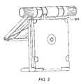
- FIG. 3illustrates a top view of the camera support mechanism with a cable slot, according to an embodiment
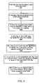
- FIG. 4illustrates a method for mounting a camera to a display using the camera support mechanism, according to an embodiment
- FIG. 5illustrates an exploded view of another embodiment of a camera support mechanism, according to an embodiment
- FIGS. 6 a and 6 billustrate cross sectional views of an embodiment of the camera support mechanism with an adjustment knob ( 6 a ) and a motor ( 6 b ), according to an embodiment
- FIG. 7illustrates an exploded view of rear leg securing assembly, according to an embodiment
- FIG. 8illustrates an exploded view of an upper deck adjustment assembly, according to an embodiment
- FIGS. 9 a - 9 cillustrate various views of the upper deck adjustment assembly, according to an embodiment.
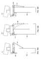
- FIGS. 10 a - 10 cillustrate various configurations for the camera support mechanism on different display types, according to an embodiment.
- a camera support mechanism (CSM) 101may be used as a mount to mount a camera on top of a display (e.g., a computer monitor or High Definition (HD) television).
- the CSM 101may be used with a HD video conferencing pan-tilt-zoom camera, or may be used for mounting any object on top of another object with a variable shape and thickness. This could be adapted, for example, to place a Digital Versatile Disc (DVD) player and/or a satellite receiver on top of the display.
- DVDDigital Versatile Disc
- the CSM 101may have an upper deck 103 (which may be flat) that folds open to access a tripod mount screw 115 that couples the camera to the CSM 101 . Other fasteners may also be used to couple the camera to the CSM 101 .
- the CSMmay not have a flat top that folds open. After attaching the camera to the top of the CSM 101 , the CSM 101 may be placed on the top of the display device (e.g., in the center).
- the CSM 101may have an adjustable front lip 105 that abuts (i.e., contacts for alignment to and/or is substantially flush with) the top front edge of the display device. Other adjustment ranges are also contemplated.
- the adjustable front lip 105may be adjusted to engage a front of the display.
- the front lipmay be fixed relative to the CSM 101 (i.e., not be adjustable).
- the front lip 105may be long enough to fit over the front part of a curved monitor.
- the front lip 105may be attached to the lower deck 119 through a mount screw 203 . Other fasteners between the front lip 105 and the lower deck 119 are also contemplated. In some embodiments, the front lip 105 may be attached to the lower deck 119 without a fastener. In some embodiments, the front lip 105 may have a foam rubber pad 107 . In some embodiments, the front lip 105 may have two separate pads that may cushion the contact with the display. Other numbers, shapes, and materials for the offsets are also contemplated. In some embodiments, multiple pads 107 may be used to engage the CSM 101 with display devices that have either a concave or a convex front surface.
- the CSM 101may also work with display devices that have either a concave or a convex surface if only a single pad is used.
- the front lip 105may be adjusted to one of a number of set positions (as determined by the mounting screw holes 251 in the lower deck 119 ) so that the CSM 101 can accommodate even extremely thin screens that may be wall mounted.
- a slotmay be used instead of mounting screw holes 251 .
- the CSM 101 and cameramay actually extend a couple of inches in front of the display in order for the back of the CSM 101 to not make contact with the wall.
- the CSMmay make contact with the wall.
- the CSMmay be mounted to the wall.
- the adjustment knob 109when the CSM 101 is placed on the display, a user may tighten adjustment knob 109 on one side of the pivot assembly 153 at the rear of the CSM 101 .
- the adjustment knob 109may be a large knurled plastic knob. Other materials and shapes for the adjustment knob 109 are also contemplated.
- a motormay be used in place of or in addition to the adjustment knob to adjust the adjustable rear leg 111 . Tightening the adjustment knob 109 may rotate the adjustable rear leg 111 towards the back of the display. In some embodiments, the rear leg 111 may rotate from flat and parallel to the top of the display to perpendicular to the top of the display.
- the rear leg 111may accommodate different shaped displays (e.g., monitor based displays, rear-projection LCD displays, and plasma screens).
- monitor based displayse.g., monitor based displays, rear-projection LCD displays, and plasma screens.
- further tightening of the adjustment knobs 109may apply additional pressure.
- the rear leg 111may be tightened to lock the rear leg 111 firmly against the back of the display at that position.
- the lower deck face gear 209 and leg face gear 211may be used to move and/or tighten the rear leg 111 .
- the two face gears 209 , 211may disengage to allow the rear leg 111 to swing against the back of the display. Then the face gears 209 , 211 may engage to lock the rear leg 111 in one position.
- conical mating surfacesmay be used in place of face gears 209 , 211 .
- conical mating surfaces(similar to a conical clutch) may be used to allow continuous stopping positions for the rear leg 111 .
- discrete stopping positionsmay be used.
- the rear leg 111may have a compliant tip (e.g., comprised of foam/rubber) 117 for better gripping.
- the CSM 101may accommodate variable slope on the display from front to back using the compliant tip 117 .
- the cameramay be relatively flat but may not be perfectly lined up with the top of the display device resulting in a tilt offset.
- the angle of the cameramay be adjusted up or down approximately in a range of plus or minus 10 degrees (other ranges are also contemplated).
- the lifter knob 201may interact with a lifter cam 205 to elevate or lower the upper deck 103 to adjust the angle of the camera.
- the lifter knob 201may be made of knurled plastic. Other materials and shapes are also contemplated.
- the upper deck 103may be pivotably coupled to the lower deck 119 on the opposing side of the lower deck 119 than the adjustment knobs.
- the back of the CSM 101may have a slot 301 (as seen in FIG. 3 ) in front of the adjustment knobs that may be used to route a camera cable without increasing the overall depth of the CSM 101 by having the camera cable wrap around the back of the CSM 101 .
- Other locations for the slot 301are also contemplated.
- the electronics from the camera in the video conferencing systemmay be split in order to use a smaller mount for fitting the camera on top of the display device.
- FIG. 4illustrates an embodiment of a method for mounting a camera to a display using the CSM 101 . It is noted that in various embodiments one or more of the method elements may be performed concurrently, in a different order, or be omitted. Additional elements may be performed as desired.
- the rear leg 111may be folded open from the CSM 101 .
- the rear leg 111may originally be folded on top or on the bottom of the CSM 101 to make the CSM more compact when not in use.
- a cameramay be coupled to the CSM 101 using a fastener.
- the cameramay be coupled to the CSM 101 with a tripod mount screw 115 .
- the upper deckmay be pivoted open to access the tripod mount screw 115 .
- other fastenersmay be used (e.g., the camera may be mounted to the CSM through adhesive or the CSM may be built into the camera).
- a front lip 105 coupled to the CSM 101may be adjusted to abut a front edge of a display.
- the front lip 105may be mounted toward the center of the CSM 101 to reduce the amount of space need behind the display for the rear leg 111 and pivot assembly 109 .
- a rear leg 111 on the CSM 101may be tightened onto the rear of the display.
- the adjustment knob 109may be tightened to tighten the adjustable rear leg 111 against a back of the display.
- the tightening of the adjustment knob 109may apply a tightening force once the rear leg 111 makes contact with the back of the display.
- a motormay tighten the CSM 101 onto the display.
- the front lip 105 and rear leg 111may secure the CSM 101 to the display.
- a compliant tip 117 on the adjustable rear leg 111may engage the back of a display to inhibit slipping of the adjustable rear leg 111 .
- a substantially similar user interaction with the adjustment knobmay rotate the adjustable rear leg, tighten the adjustable rear leg onto the display, and lock the adjustable rear leg onto the display.
- Other substantially similar user interactionsare also contemplated (e.g., pressing a button to activate a motor to tighten the adjustable rear leg).
- a compliant tip on the adjustable rear legmay be engaged with a back of a display to inhibit slipping of the adjustable rear leg.
- the CSM 101may be aligned with a top of the display using a lifter knob 201 coupled to the CSM 101 .
- FIG. 5illustrates an exploded view of another embodiment of the CSM.
- FIG. 6illustrates a cross sectional view of the embodiment of the CSM shown in FIG. 5 .
- FIGS. 5 and 6illustrate various different embodiments of configurations for different components within the CSM.
- the rear leg securing assembly(as further seen in FIG. 7 ) and upper deck adjustment assembly may have different configurations.
- FIGS. 5-7illustrate an embodiment of an exploded view of a rear leg securing assembly.
- the adjustment knob 509may screw onto a threaded rod 513 .
- the tapered member 523has offset features on its outer surface that engage with offset features on the inner edge of the upper adjustable rear leg housing 544 .
- the barrel 525may have offset features on its outer surface that engage with offset features on the inside surface of the lower deck 529 .
- the adjustment knob 509may engage the rubber washer 510 , which, in turn, may rotate the tapered member 523 .
- a motor 699may perform the described functions of the adjustment knob 509 .
- a motor 699may be activated by a button to engage the rubber washer and rotate the tapered member 523 .
- the adjustment knob 509may engage a rubber washer 510 that may in turn twist the tapered member 523 .
- the tapered member 523may engage barrel 525 through friction between the sides of the tapered member 523 and the barrel 525 .
- the barrel 525may engage and rotate the rear leg 543 through the offset outer edges of the barrel engaging the offset inner edge of the upper adjustable rear leg housing 544 . After the rear leg 543 comes to rest against the back of a display and stops rotating, the barrel 525 may stop rotating relative to the tapered member 523 .
- the friction between the adjustment knob 509 and the rubber washer 510may not be sufficient to turn the rubber washer and/or tapered member 523 once the rear leg 543 has made contact with the back of the display.
- the friction between the tapered member 523 and the barrel 525may not be sufficient to turn the barrel 525 relative to the tapered member 523 .
- the tapered member 523may be forced inward against the barrel 525 increasing the friction between the sides of the tapered member 523 and the barrel 525 . The increased friction may result in a better hold on the rear leg 543 .
- the front lip 545may be continuously adjustable on the lower deck 599 through screw 503 and slot 504 .
- guide markings 575may be provided to guide the placement of the front lip 545 .
- Placement holesmay be provided to give additional support to the front lip at certain locations along the slot (e.g., other fasteners may be used with the additional holes). In some embodiments, placement holes may also be used for more specific placements of the upper deck in place of the slot.
- the adjustable front lip 545may be adjusted for the thickness of the display the camera is to be mounted on.
- FIGS. 8 and 9illustrate various views of the upper deck leveler, according to an embodiment.
- the lifter insert 537 and the lifter nut 538are bonded together and act as one part.
- the spring 520may load the lifter insert/nut 537 / 538 against the friction washer 531 which in turn is loaded against the lower deck 599 . This may provide friction to support the weight of the upper deck 501 and camera.
- a lifter insert 537may rotate inside of a lifter nut 538 configured to lift (or lower) the upper deck 501 by applying an upward force on the upper deck extension tab 532 .
- the lifter insert 537may fit inside the lifter nut 538 to engage the lifter nut 538 and turn it.
- a lip of the lifter nut 538may engage the upper deck extension tab 532 to lift or lower it.
- spring 520may apply pressure to the lifter insert 537 to keep it in contact with the lifter nut 538 .
- FIG. 9 cis a cross sectional view illustrating an embodiment of how the lifter nut 538 may engage the upper deck extension tab 532 to lift or lower the upper deck 501 .
- FIGS. 10 a - 10 cillustrate various configurations for the camera support mechanism on different display types, according to an embodiment.
- FIG. 10 aillustrates a configuration for the CSM supporting a camera 1011 on top of a flat screen display 1001 .
- the rear leg 543may be in contact with the back of the display 1001 .
- the rear leg 543 together with the front lip 545may secure the camera 1011 to the top of the display.
- the upper deck 501may be adjustable to slant the camera 1011 relative to the CSM.
- FIG. 10 billustrates an embodiment of a CSM supporting a camera 1011 on a display 1003 with a contour back.
- the rear leg 543may be at a greater angle relative to the rest of the CSM because the rear leg 543 may make contact with the contour of the back of the display at a greater angle than if the CSM was mounting to a flat screen display.
- FIG. 10 cillustrates an embodiment of the CSM with an adjusted front lip.
- the front lip 545may be adjusted forward (e.g., by moving a fastener in a slot as discussed above). Bringing the front lip 545 forward may bring the rear leg 543 and rear leg securing assembly 1051 closer to the rear of the display 1005 . This may allow the CSM to be used on a flat screen display that is mounted to a wall. If mounted to a wall, there may be less space available for the rear leg 543 and rear leg securing assembly 1051 behind the display 1005 .
- Embodiments of these methodsmay be implemented by program instructions stored in a memory medium or carrier medium.
- a memory mediummay include any of various types of memory devices or storage devices.
- the term “memory medium”is intended to include an installation medium, e.g., a Compact Disc Read Only Memory (CD-ROM), floppy disks, or tape device; a computer system memory or random access memory such as Dynamic Random Access Memory (DRAM), Double Data Rate Random Access Memory (DDR RAM), Static Random Access Memory (SRAM), Extended Data Out Random Access Memory (EDO RAM), Rambus Random Access Memory (RAM), etc.; or a non-volatile memory such as a magnetic media, e.g., a hard drive, or optical storage.
- DRAMDynamic Random Access Memory
- DDR RAMDouble Data Rate Random Access Memory
- SRAMStatic Random Access Memory
- EEO RAMExtended Data Out Random Access Memory
- RAMRambus Random Access Memory
- non-volatile memorysuch as a magnetic media, e.g., a hard drive
- the memory mediummay comprise other types of memory as well, or combinations thereof.
- the memory mediummay be located in a first computer in which the programs are executed, or may be located in a second different computer that connects to the first computer over a network, such as the Internet. In the latter instance, the second computer may provide program instructions to the first computer for execution.
- the term “memory medium”may include two or more memory mediums that may reside in different locations, e.g., in different computers that are connected over a network.
- the computer systemmay include a memory medium(s) on which one or more computer programs or software components according to one embodiment of the present invention may be stored.
- the memory mediummay store one or more programs that are executable to perform the methods described herein.
- the memory mediummay also store operating system software, as well as other software for operation of the computer system.
Landscapes
- Engineering & Computer Science (AREA)
- General Engineering & Computer Science (AREA)
- Mechanical Engineering (AREA)
- Studio Devices (AREA)
- Devices For Indicating Variable Information By Combining Individual Elements (AREA)
Abstract
Description
- U.S. Provisional Patent Application titled “Speakerphone”, Ser. No. 60/619,303, which was filed Oct. 15, 2004, whose inventors are William V. Oxford, Michael L. Kenoyer, and Simon Dudley is hereby incorporated by reference in its entirety as though fully and completely set forth herein.
- U.S. Provisional Patent Application titled “Speakerphone”, Ser. No. 60/634,315 which was filed Dec. 8, 2004, whose inventors are William V. Oxford, Michael L. Kenoyer and Simon Dudley which is hereby incorporated by reference in its entirety as though fully and completely set forth herein.
- U.S. Provisional Patent Application titled “Video Conferencing Speakerphone”, Ser. No. 60/619,212, which was filed Oct. 15, 2004, whose inventors are Michael L. Kenoyer, Craig B. Malloy, and Wayne E. Mock is hereby incorporated by reference in its entirety as though fully and completely set forth herein.
- U.S. Provisional Patent Application titled “Video Conference Call System”, Ser. No. 60/619,210, which was filed Oct. 15, 2004, whose inventors are Jonathan W. Tracey, Craig B. Malloy, Michael L. Kenoyer, Michael V. Jenkins, Ashish Goyal, and Michael J. Burkett, is hereby incorporated by reference in its entirety as though fully and completely set forth herein.
Claims (20)
Priority Applications (1)
| Application Number | Priority Date | Filing Date | Title |
|---|---|---|---|
| US11/252,222US7572073B2 (en) | 2004-10-15 | 2005-10-17 | Camera support mechanism |
Applications Claiming Priority (3)
| Application Number | Priority Date | Filing Date | Title |
|---|---|---|---|
| US61922704P | 2004-10-15 | 2004-10-15 | |
| US67596405P | 2005-04-29 | 2005-04-29 | |
| US11/252,222US7572073B2 (en) | 2004-10-15 | 2005-10-17 | Camera support mechanism |
Publications (2)
| Publication Number | Publication Date |
|---|---|
| US20060088308A1 US20060088308A1 (en) | 2006-04-27 |
| US7572073B2true US7572073B2 (en) | 2009-08-11 |
Family
ID=36206287
Family Applications (1)
| Application Number | Title | Priority Date | Filing Date |
|---|---|---|---|
| US11/252,222Expired - Fee RelatedUS7572073B2 (en) | 2004-10-15 | 2005-10-17 | Camera support mechanism |
Country Status (1)
| Country | Link |
|---|---|
| US (1) | US7572073B2 (en) |
Cited By (24)
| Publication number | Priority date | Publication date | Assignee | Title |
|---|---|---|---|---|
| US20080035815A1 (en)* | 2006-04-07 | 2008-02-14 | David Yim | Speaker With Monitor Mountable Stand |
| US20100039552A1 (en)* | 2008-08-12 | 2010-02-18 | Kuo-Hua Kao | Webcam module having a clamping device |
| US20110208905A1 (en)* | 2008-12-09 | 2011-08-25 | Rambus Inc. | Non-Volatile Memory Device For Concurrent And Pipelined Memory Operations |
| US8091844B1 (en)* | 2008-11-26 | 2012-01-10 | Bragg Dana C | Air conditioner support device |
| US20120137499A1 (en)* | 2010-12-04 | 2012-06-07 | Pawan Agnihotri | Universal adjustable bracket apparatus for supporting air conditioners and other devices |
| US20130048817A1 (en)* | 2011-08-24 | 2013-02-28 | Logitech Europe S.A. | Multi-linkage clip for camera and other devices |
| US9179794B2 (en)* | 2013-08-02 | 2015-11-10 | Nation Wide Products, Llc | Supporting an object at a window of a building by applying opposing forces to an interior surface and an exterior surface of the building |
| US9323135B1 (en) | 2014-05-22 | 2016-04-26 | Carlos J. Veloso | Multi-function foldable support arm |
| US9909712B1 (en) | 2013-08-02 | 2018-03-06 | Nation Wide Products Llc | Supporting an object at a window of a building by applying opposing forces to an interior surface and an exterior surface of the building with a first member and second member joined about their intermediate sections |
| US10436383B1 (en) | 2013-08-02 | 2019-10-08 | Nation Wide Products, Inc. | Supporting an object at a window of a building using an adjustable support apparatus |
| USD902971S1 (en) | 2018-03-07 | 2020-11-24 | Dolby Laboratories Licensing Corporation | Camera system |
| USD907089S1 (en) | 2018-08-23 | 2021-01-05 | Dolby Laboratories Licensing Corporation | Video camera |
| USD909445S1 (en) | 2018-03-07 | 2021-02-02 | Dolby Laboratories Licensing Corporation | Camera system |
| US11039049B2 (en) | 2018-03-07 | 2021-06-15 | Dolby Laboratories Licensing Corporation | Configurable and adjustable video conferencing apparatus |
| USD929482S1 (en) | 2019-05-18 | 2021-08-31 | Dolby Laboratories Licensing Corporation | Camera |
| US20220043477A1 (en)* | 2020-08-10 | 2022-02-10 | Razer (Asia-Pacific) Pte. Ltd. | Mount for a peripheral device |
| US11391449B1 (en) | 2021-06-23 | 2022-07-19 | Logitech Europe S.A. | Adjustable mounted portable light |
| US11506956B1 (en)* | 2021-05-28 | 2022-11-22 | Dell Products L.P. | Cylindrical camera with integrated tilt stand |
| US20230021107A1 (en)* | 2021-07-19 | 2023-01-19 | Qisda Corporation | Fixing frame and auxiliary device using the same |
| US20230136884A1 (en)* | 2021-10-29 | 2023-05-04 | Logitech Europe S.A. | Mount for a computer peripheral device |
| US20230189456A1 (en)* | 2021-12-13 | 2023-06-15 | Qisda Corporation | Display device and fixing module thereof |
| USD1014809S1 (en) | 2021-06-21 | 2024-02-13 | Logitech Europe S.A. | Light assembly |
| USD1023386S1 (en) | 2022-08-10 | 2024-04-16 | Logitech Europe S.A. | Mountable light |
| USD1083193S1 (en) | 2023-05-11 | 2025-07-08 | Logitech Europe S.A. | Light bar |
Families Citing this family (44)
| Publication number | Priority date | Publication date | Assignee | Title |
|---|---|---|---|---|
| US7789574B2 (en)* | 2007-11-16 | 2010-09-07 | Du-Bro Products, Inc. | Camera mount |
| USD589996S1 (en) | 2008-02-07 | 2009-04-07 | Lifesize Communications, Inc. | Flat mounted camera |
| USD589995S1 (en) | 2008-02-07 | 2009-04-07 | Lifesize Communications, Inc. | Mountable camera |
| USD590000S1 (en) | 2008-02-07 | 2009-04-07 | Lifesize Communications, Inc. | Camera stand |
| CN102162573B (en)* | 2011-04-15 | 2013-05-15 | 湖南省有线电视网络(集团)股份有限公司 | Bracket of television set top box |
| US10791257B2 (en)* | 2011-11-14 | 2020-09-29 | Gopro, Inc. | Positioning apparatus for photographic and video imaging and recording and system utilizing the same |
| BR102012004645A2 (en)* | 2012-03-01 | 2013-10-22 | Ibope Pesquisa De Midia E Participacoes Ltda | Hearing Aid Apparatus, Process and System |
| US8858098B1 (en)* | 2013-06-07 | 2014-10-14 | Rhino Camera Gear, LLC | Slide-able mount for an image device |
| CN104581295A (en)* | 2014-12-23 | 2015-04-29 | 贵州省广播电视信息网络股份有限公司 | Intelligent all-service terminal, facing to tri-network integration, hung on separate machine |
| CN104581300A (en)* | 2014-12-23 | 2015-04-29 | 贵州省广播电视信息网络股份有限公司 | Intelligent all-service terminal, facing to tri-network integration, hung on separate machine |
| CN104602065A (en)* | 2014-12-23 | 2015-05-06 | 贵州省广播电视信息网络股份有限公司 | Hanging type Chinese character Mi type radiating three-network integration-oriented all-service intelligent terminal |
| CN104683840A (en)* | 2014-12-23 | 2015-06-03 | 贵州省广播电视信息网络股份有限公司 | Honeycomb heat emission tri-networks integration-oriented machine-mounted full-service intelligent terminal |
| CN104581257A (en)* | 2014-12-23 | 2015-04-29 | 贵州省广播电视信息网络股份有限公司 | Machine-hung three-network integration-oriented full-service intelligent terminal |
| CN104602085A (en)* | 2014-12-23 | 2015-05-06 | 贵州省广播电视信息网络股份有限公司 | Separated hanging type three-network integration-oriented all-service intelligent terminal |
| CN104581256A (en)* | 2014-12-23 | 2015-04-29 | 贵州省广播电视信息网络股份有限公司 | Wall-hung type tri-network integration-oriented full-service intelligent terminal with *-type radiating function |
| CN104602066A (en)* | 2014-12-23 | 2015-05-06 | 贵州省广播电视信息网络股份有限公司 | Hanging type Chinese character Mi type radiating three-network integration-oriented all-service intelligent terminal |
| CN104581253A (en)* | 2014-12-23 | 2015-04-29 | 贵州省广播电视信息网络股份有限公司 | Wall-hung type tri-network integration-oriented full-service intelligent terminal with *-type radiating function |
| CN104581252A (en)* | 2014-12-23 | 2015-04-29 | 贵州省广播电视信息网络股份有限公司 | Machine-hung three-network integration-oriented full-service intelligent terminal |
| CN104581298A (en)* | 2014-12-23 | 2015-04-29 | 贵州省广播电视信息网络股份有限公司 | Intelligent all-service terminal, facing to tri-network integration, hung on separate machine |
| CN104581294A (en)* | 2014-12-23 | 2015-04-29 | 贵州省广播电视信息网络股份有限公司 | Machine-hung three-network integration-oriented full-service intelligent terminal |
| CN104581297A (en)* | 2014-12-23 | 2015-04-29 | 贵州省广播电视信息网络股份有限公司 | Machine-hung three-network integration-oriented full-service intelligent terminal |
| CN104581255A (en)* | 2014-12-23 | 2015-04-29 | 贵州省广播电视信息网络股份有限公司 | Wall-hung type tri-network integration-oriented full-service intelligent terminal with honeycomb radiating function |
| CN104602079A (en)* | 2014-12-23 | 2015-05-06 | 贵州省广播电视信息网络股份有限公司 | Separated hanging type three-network integration-oriented all-service intelligent terminal |
| CN104581296A (en)* | 2014-12-23 | 2015-04-29 | 贵州省广播电视信息网络股份有限公司 | Intelligent all-service terminal, facing to tri-network integration, hung on separate machine |
| CN104618747A (en)* | 2014-12-23 | 2015-05-13 | 贵州省广播电视信息网络股份有限公司 | Wall-mounted full-service intelligent terminal integrated with three networks |
| CN104581299A (en)* | 2014-12-23 | 2015-04-29 | 贵州省广播电视信息网络股份有限公司 | Machine-hung circular radiating three-network integration-oriented full-service intelligent terminal |
| CN104581251A (en)* | 2014-12-23 | 2015-04-29 | 贵州省广播电视信息网络股份有限公司 | Wall-hung type tri-network integration-oriented full-service intelligent terminal with honeycomb radiating function |
| CN104602075A (en)* | 2014-12-23 | 2015-05-06 | 贵州省广播电视信息网络股份有限公司 | Hanging type three-network integration-oriented all-service intelligent terminal |
| CN104581245A (en)* | 2014-12-23 | 2015-04-29 | 贵州省广播电视信息网络股份有限公司 | Machine-hung three-network integration-oriented full-service intelligent terminal |
| CN104602058A (en)* | 2014-12-23 | 2015-05-06 | 贵州省广播电视信息网络股份有限公司 | Hanging type three-network integration-oriented all-service intelligent terminal |
| CN104602084A (en)* | 2014-12-23 | 2015-05-06 | 贵州省广播电视信息网络股份有限公司 | Separated hanging type three-network integration-oriented all-service intelligent terminal |
| CN104602063A (en)* | 2014-12-23 | 2015-05-06 | 贵州省广播电视信息网络股份有限公司 | Separated hanging type three-network integration-oriented all-service intelligent terminal |
| CN104581302A (en)* | 2014-12-23 | 2015-04-29 | 贵州省广播电视信息网络股份有限公司 | Machine-mounted type triple-network-convergence-oriented full-service intelligent terminal with *-shaped heat dissipation holes |
| CN104581254A (en)* | 2014-12-23 | 2015-04-29 | 贵州省广播电视信息网络股份有限公司 | Wall-hung type tri-network integration-oriented full-service intelligent terminal |
| CN104602072A (en)* | 2014-12-23 | 2015-05-06 | 贵州省广播电视信息网络股份有限公司 | Hanging type honeycomb radiating three-network integration-oriented all-service intelligent terminal |
| CN104683838A (en)* | 2014-12-23 | 2015-06-03 | 贵州省广播电视信息网络股份有限公司 | Wall hanging type asterisk-shaped heat radiation three-network-integration-oriented full-service intelligent terminal |
| FR3031161A1 (en)* | 2014-12-24 | 2016-07-01 | Bobino Bv | TABLET FOR WEARING OBJECTS ABOVE A TELEVISION SCREEN TYPE MEDIA OR COMPUTER |
| CN104581310A (en)* | 2014-12-30 | 2015-04-29 | 贵州省广播电视信息网络股份有限公司 | Machine-hung circular radiating all-service intelligent terminal using integration of three networks as orientation |
| CN104581308A (en)* | 2014-12-30 | 2015-04-29 | 贵州省广播电视信息网络股份有限公司 | Machine-hung all-service intelligent terminal radiating in shape of Chinese character 'mi' and using integration of three networks as orientation |
| CN104602090A (en)* | 2014-12-30 | 2015-05-06 | 贵州省广播电视信息网络股份有限公司 | Hanging type round radiating three-network integration-oriented all-service intelligent terminal |
| CN104581309A (en)* | 2014-12-30 | 2015-04-29 | 贵州省广播电视信息网络股份有限公司 | Machine-hung rectangular radiating all-service intelligent terminal using integration of three networks as orientation |
| CN104581312A (en)* | 2014-12-30 | 2015-04-29 | 贵州省广播电视信息网络股份有限公司 | Machine-hung circular radiating all-service intelligent terminal using integration of three networks as orientation |
| CN104581311A (en)* | 2014-12-31 | 2015-04-29 | 贵州省广播电视信息网络股份有限公司 | Machine-hung rectangular radiating all-service intelligent terminal using integration of three networks as orientation |
| US10250783B2 (en) | 2016-07-07 | 2019-04-02 | Google Llc | Magnetic mount assembly of a camera |
Citations (41)
| Publication number | Priority date | Publication date | Assignee | Title |
|---|---|---|---|---|
| US4264928A (en) | 1979-11-05 | 1981-04-28 | Schober Gary W | Conference video system |
| US5322255A (en) | 1991-03-23 | 1994-06-21 | International Business Machines Corporation | Mounting bracket |
| US5374971A (en) | 1993-03-12 | 1994-12-20 | Picturetel Corporation | Two-view video camera stand and support method |
| US5486853A (en) | 1994-12-13 | 1996-01-23 | Picturetel Corporation | Electrical cable interface for electronic camera |
| US5515099A (en) | 1993-10-20 | 1996-05-07 | Video Conferencing Systems, Inc. | Video conferencing system controlled by menu and pointer |
| US5537157A (en) | 1993-04-21 | 1996-07-16 | Kinya Washino | Multi-format audio/video production system |
| US5612733A (en) | 1994-07-18 | 1997-03-18 | C-Phone Corporation | Optics orienting arrangement for videoconferencing system |
| US5617539A (en) | 1993-10-01 | 1997-04-01 | Vicor, Inc. | Multimedia collaboration system with separate data network and A/V network controlled by information transmitting on the data network |
| US5633681A (en) | 1995-03-06 | 1997-05-27 | Picturetel Corporation | Electrically controlled camera positioning system |
| US5692159A (en) | 1995-05-19 | 1997-11-25 | Digital Equipment Corporation | Configurable digital signal interface using field programmable gate array to reformat data |
| US5751338A (en) | 1994-12-30 | 1998-05-12 | Visionary Corporate Technologies | Methods and systems for multimedia communications via public telephone networks |
| US5821987A (en) | 1992-06-23 | 1998-10-13 | Larson; Craig R. | Videophone for simultaneous audio and video communication via a standard telephone line |
| US5855343A (en)* | 1997-03-07 | 1999-01-05 | Irez Research, Corporation | Camera clip |
| US6072522A (en) | 1997-06-04 | 2000-06-06 | Cgc Designs | Video conferencing apparatus for group video conferencing |
| US6239841B1 (en) | 1999-09-20 | 2001-05-29 | Primax Electronics Ltd. | Clamping apparatus for fixing a small electronic camera on an LCD panel |
| US6356308B1 (en) | 1998-06-11 | 2002-03-12 | Polycom, Inc. | Device for rotatably positioning a camera or similar article about two orthogonal axes |
| US6431507B2 (en)* | 2000-03-01 | 2002-08-13 | Logitech Europe S.A. | Video camera support device |
| US6481681B1 (en)* | 2000-08-30 | 2002-11-19 | 3Com Corporation | Clip apparatus for a laptop computer |
| US6594688B2 (en) | 1993-10-01 | 2003-07-15 | Collaboration Properties, Inc. | Dedicated echo canceler for a workstation |
| US6643462B2 (en) | 2001-03-14 | 2003-11-04 | Leica Camera Ag | Variable viewfinder for wide angle shots |
| US6663066B1 (en)* | 2002-10-22 | 2003-12-16 | Kye Systems Corp. | Multi-function support |
| US20040001137A1 (en) | 2002-06-27 | 2004-01-01 | Ross Cutler | Integrated design for omni-directional camera and microphone array |
| US6679463B1 (en)* | 2003-06-11 | 2004-01-20 | Kye Systems Corp. | Support with multi-stage clamping mechanism |
| US6724619B2 (en) | 2002-06-19 | 2004-04-20 | Bill Kwong | Console drive |
| US6731340B1 (en) | 1999-09-03 | 2004-05-04 | Mitac International Corp. | Surface-mount video camera adapted to be mounted on and used with a personal computer |
| US6731334B1 (en) | 1995-07-31 | 2004-05-04 | Forgent Networks, Inc. | Automatic voice tracking camera system and method of operation |
| US6738094B1 (en)* | 1998-11-09 | 2004-05-18 | Sharp Kabushiki Kaisha | Video camera |
| US20040130655A1 (en)* | 2003-01-06 | 2004-07-08 | Kooigi Yanakawa | Network camera |
| US20040183897A1 (en) | 2001-08-07 | 2004-09-23 | Michael Kenoyer | System and method for high resolution videoconferencing |
| US6809358B2 (en) | 2002-02-05 | 2004-10-26 | E-Phocus, Inc. | Photoconductor on active pixel image sensor |
| US6816904B1 (en) | 1997-11-04 | 2004-11-09 | Collaboration Properties, Inc. | Networked video multimedia storage server environment |
| US6845954B1 (en)* | 2003-08-29 | 2005-01-25 | Logitech Europe S.A. | Kinematically reconfigurable camera mount |
| US6850265B1 (en) | 2000-04-13 | 2005-02-01 | Koninklijke Philips Electronics N.V. | Method and apparatus for tracking moving objects using combined video and audio information in video conferencing and other applications |
| US6970202B1 (en) | 2000-06-27 | 2005-11-29 | Eastman Kodak Company | Device for mounting a camera on a computer |
| US20050265712A1 (en)* | 2004-05-28 | 2005-12-01 | Creative Technology Ltd. | Three way video camera base |
| US6980485B2 (en) | 2001-10-25 | 2005-12-27 | Polycom, Inc. | Automatic camera tracking using beamforming |
| US7038709B1 (en) | 2000-11-01 | 2006-05-02 | Gilbert Verghese | System and method for tracking a subject |
| US20060170817A1 (en)* | 2005-02-03 | 2006-08-03 | Behavior Tech Computer Corp. | Camera assembly structure |
| US7202904B2 (en) | 2003-10-22 | 2007-04-10 | E-Benk Tech Co., Ltd. | Video monitoring device |
| US7202903B2 (en)* | 2003-09-25 | 2007-04-10 | Inventec Multimedia & Telecom Corporation | Clipping dock for network video cameras |
| US7219866B2 (en)* | 2005-07-13 | 2007-05-22 | Hewlett-Packard Development Company, L.P. | Spring loaded clamping mechanism |
- 2005
- 2005-10-17USUS11/252,222patent/US7572073B2/ennot_activeExpired - Fee Related
Patent Citations (47)
| Publication number | Priority date | Publication date | Assignee | Title |
|---|---|---|---|---|
| US4264928A (en) | 1979-11-05 | 1981-04-28 | Schober Gary W | Conference video system |
| US5322255A (en) | 1991-03-23 | 1994-06-21 | International Business Machines Corporation | Mounting bracket |
| US5821987A (en) | 1992-06-23 | 1998-10-13 | Larson; Craig R. | Videophone for simultaneous audio and video communication via a standard telephone line |
| US5374971A (en) | 1993-03-12 | 1994-12-20 | Picturetel Corporation | Two-view video camera stand and support method |
| US5537157A (en) | 1993-04-21 | 1996-07-16 | Kinya Washino | Multi-format audio/video production system |
| US5689641A (en) | 1993-10-01 | 1997-11-18 | Vicor, Inc. | Multimedia collaboration system arrangement for routing compressed AV signal through a participant site without decompressing the AV signal |
| US6594688B2 (en) | 1993-10-01 | 2003-07-15 | Collaboration Properties, Inc. | Dedicated echo canceler for a workstation |
| US5617539A (en) | 1993-10-01 | 1997-04-01 | Vicor, Inc. | Multimedia collaboration system with separate data network and A/V network controlled by information transmitting on the data network |
| US5515099A (en) | 1993-10-20 | 1996-05-07 | Video Conferencing Systems, Inc. | Video conferencing system controlled by menu and pointer |
| US5528289A (en) | 1993-10-20 | 1996-06-18 | Videoconferencing Systems, Inc. | Method for automatically adjusting a videoconferencing system camera to center an object |
| US5598209A (en) | 1993-10-20 | 1997-01-28 | Videoconferencing Systems, Inc. | Method for automatically adjusting a video conferencing system camera |
| US5612733A (en) | 1994-07-18 | 1997-03-18 | C-Phone Corporation | Optics orienting arrangement for videoconferencing system |
| US5486853A (en) | 1994-12-13 | 1996-01-23 | Picturetel Corporation | Electrical cable interface for electronic camera |
| US5751338A (en) | 1994-12-30 | 1998-05-12 | Visionary Corporate Technologies | Methods and systems for multimedia communications via public telephone networks |
| US5633681A (en) | 1995-03-06 | 1997-05-27 | Picturetel Corporation | Electrically controlled camera positioning system |
| US5692159A (en) | 1995-05-19 | 1997-11-25 | Digital Equipment Corporation | Configurable digital signal interface using field programmable gate array to reformat data |
| US6731334B1 (en) | 1995-07-31 | 2004-05-04 | Forgent Networks, Inc. | Automatic voice tracking camera system and method of operation |
| US5855343A (en)* | 1997-03-07 | 1999-01-05 | Irez Research, Corporation | Camera clip |
| US6072522A (en) | 1997-06-04 | 2000-06-06 | Cgc Designs | Video conferencing apparatus for group video conferencing |
| US6816904B1 (en) | 1997-11-04 | 2004-11-09 | Collaboration Properties, Inc. | Networked video multimedia storage server environment |
| US7046295B2 (en) | 1998-06-11 | 2006-05-16 | Polycom, Inc. | System and method for rotatably positioning a camera or similar article about two orthogonal axes |
| US6356308B1 (en) | 1998-06-11 | 2002-03-12 | Polycom, Inc. | Device for rotatably positioning a camera or similar article about two orthogonal axes |
| US6738094B1 (en)* | 1998-11-09 | 2004-05-18 | Sharp Kabushiki Kaisha | Video camera |
| US6731340B1 (en) | 1999-09-03 | 2004-05-04 | Mitac International Corp. | Surface-mount video camera adapted to be mounted on and used with a personal computer |
| US6239841B1 (en) | 1999-09-20 | 2001-05-29 | Primax Electronics Ltd. | Clamping apparatus for fixing a small electronic camera on an LCD panel |
| US6431507B2 (en)* | 2000-03-01 | 2002-08-13 | Logitech Europe S.A. | Video camera support device |
| US6850265B1 (en) | 2000-04-13 | 2005-02-01 | Koninklijke Philips Electronics N.V. | Method and apparatus for tracking moving objects using combined video and audio information in video conferencing and other applications |
| US6970202B1 (en) | 2000-06-27 | 2005-11-29 | Eastman Kodak Company | Device for mounting a camera on a computer |
| US6481681B1 (en)* | 2000-08-30 | 2002-11-19 | 3Com Corporation | Clip apparatus for a laptop computer |
| US7038709B1 (en) | 2000-11-01 | 2006-05-02 | Gilbert Verghese | System and method for tracking a subject |
| US6643462B2 (en) | 2001-03-14 | 2003-11-04 | Leica Camera Ag | Variable viewfinder for wide angle shots |
| US20040183897A1 (en) | 2001-08-07 | 2004-09-23 | Michael Kenoyer | System and method for high resolution videoconferencing |
| US6980485B2 (en) | 2001-10-25 | 2005-12-27 | Polycom, Inc. | Automatic camera tracking using beamforming |
| US6809358B2 (en) | 2002-02-05 | 2004-10-26 | E-Phocus, Inc. | Photoconductor on active pixel image sensor |
| US6724619B2 (en) | 2002-06-19 | 2004-04-20 | Bill Kwong | Console drive |
| US20040001137A1 (en) | 2002-06-27 | 2004-01-01 | Ross Cutler | Integrated design for omni-directional camera and microphone array |
| US6663066B1 (en)* | 2002-10-22 | 2003-12-16 | Kye Systems Corp. | Multi-function support |
| US20040130655A1 (en)* | 2003-01-06 | 2004-07-08 | Kooigi Yanakawa | Network camera |
| US6679463B1 (en)* | 2003-06-11 | 2004-01-20 | Kye Systems Corp. | Support with multi-stage clamping mechanism |
| US6845954B1 (en)* | 2003-08-29 | 2005-01-25 | Logitech Europe S.A. | Kinematically reconfigurable camera mount |
| US7202903B2 (en)* | 2003-09-25 | 2007-04-10 | Inventec Multimedia & Telecom Corporation | Clipping dock for network video cameras |
| US7202904B2 (en) | 2003-10-22 | 2007-04-10 | E-Benk Tech Co., Ltd. | Video monitoring device |
| US20050265712A1 (en)* | 2004-05-28 | 2005-12-01 | Creative Technology Ltd. | Three way video camera base |
| US7066664B1 (en) | 2004-05-28 | 2006-06-27 | Creative Technology Ltd | Three way video camera base |
| US7048454B2 (en) | 2004-05-28 | 2006-05-23 | Creative Technology Ltd | Three way video camera base |
| US20060170817A1 (en)* | 2005-02-03 | 2006-08-03 | Behavior Tech Computer Corp. | Camera assembly structure |
| US7219866B2 (en)* | 2005-07-13 | 2007-05-22 | Hewlett-Packard Development Company, L.P. | Spring loaded clamping mechanism |
Non-Patent Citations (6)
| Title |
|---|
| "A history of video conferencing (VC) technology" http://web.archive.org/web/20030622161425/http://myhome.hanafos.com/~soonjp/vchx.html (web archive dated Jun. 22, 2003); 5 pages. |
| "MediaMax Operations Manual"; May 1992; 342 pages; VideoTelecom; Austin, TX. |
| "MultiMax Operations Manual"; Nov. 1992; 135 pages; VideoTelecom; Austin, TX. |
| "Polycom Executive Collection"; Jun. 2003; 4 pages; Polycom, Inc.; Pleasanton, CA. |
| Peter Meyers; "Adding Eye Contact to Your Web Chats"; The New York Times; Sep. 4, 2003; 5 pages. |
| Ross Cutler, Yong Rui, Anoop Gupta, JJ Cadiz, Ivan Tashev, Li-Wei He, Alex Colburn, Zhengyou Zhang, Zicheng Liu and Steve Silverberg; "Distributed Meetings: A Meeting Capture and Broadcasting System"; Multimedia '02; Dec. 2002; 10 pages; Microsoft Research; Redmond, WA. |
Cited By (40)
| Publication number | Priority date | Publication date | Assignee | Title |
|---|---|---|---|---|
| US7931243B2 (en)* | 2006-04-07 | 2011-04-26 | Logitech Europe S.A. | Speaker with monitor mountable stand |
| US8313069B2 (en)* | 2006-04-07 | 2012-11-20 | Logitech Europe S.A. | Speaker with monitor mountable stand |
| US20080035815A1 (en)* | 2006-04-07 | 2008-02-14 | David Yim | Speaker With Monitor Mountable Stand |
| US20100039552A1 (en)* | 2008-08-12 | 2010-02-18 | Kuo-Hua Kao | Webcam module having a clamping device |
| US8054378B2 (en)* | 2008-08-12 | 2011-11-08 | Silitek Electronic (Guangzhou) Co., Ltd. | Webcam module having a clamping device |
| US8091844B1 (en)* | 2008-11-26 | 2012-01-10 | Bragg Dana C | Air conditioner support device |
| US20110208905A1 (en)* | 2008-12-09 | 2011-08-25 | Rambus Inc. | Non-Volatile Memory Device For Concurrent And Pipelined Memory Operations |
| US8533955B2 (en)* | 2010-12-04 | 2013-09-17 | Pawan Agnihotri | Universal adjustable bracket apparatus for supporting air conditioners and other devices |
| US20120137499A1 (en)* | 2010-12-04 | 2012-06-07 | Pawan Agnihotri | Universal adjustable bracket apparatus for supporting air conditioners and other devices |
| US20130048817A1 (en)* | 2011-08-24 | 2013-02-28 | Logitech Europe S.A. | Multi-linkage clip for camera and other devices |
| US9169962B2 (en)* | 2011-08-24 | 2015-10-27 | Logitech Europe S.A. | Multi-linkage clip for camera and other devices |
| US9179794B2 (en)* | 2013-08-02 | 2015-11-10 | Nation Wide Products, Llc | Supporting an object at a window of a building by applying opposing forces to an interior surface and an exterior surface of the building |
| US9909712B1 (en) | 2013-08-02 | 2018-03-06 | Nation Wide Products Llc | Supporting an object at a window of a building by applying opposing forces to an interior surface and an exterior surface of the building with a first member and second member joined about their intermediate sections |
| US10104964B2 (en) | 2013-08-02 | 2018-10-23 | Nation Wide Products Llc | Supporting an object at a window of a building by applying opposing forces to an interior surface and an exterior surface of the building |
| US10436383B1 (en) | 2013-08-02 | 2019-10-08 | Nation Wide Products, Inc. | Supporting an object at a window of a building using an adjustable support apparatus |
| US10743664B2 (en) | 2013-08-02 | 2020-08-18 | Nation Wide Products Llc | Supporting an object at a window of a building by applying opposing forces to an interior surface and an exterior surface of the building |
| US9323135B1 (en) | 2014-05-22 | 2016-04-26 | Carlos J. Veloso | Multi-function foldable support arm |
| US11039049B2 (en) | 2018-03-07 | 2021-06-15 | Dolby Laboratories Licensing Corporation | Configurable and adjustable video conferencing apparatus |
| USD909445S1 (en) | 2018-03-07 | 2021-02-02 | Dolby Laboratories Licensing Corporation | Camera system |
| USD902971S1 (en) | 2018-03-07 | 2020-11-24 | Dolby Laboratories Licensing Corporation | Camera system |
| USD939605S1 (en) | 2018-03-07 | 2021-12-28 | Dolby Laboratories Licensing Corporation | Camera system |
| USD907089S1 (en) | 2018-08-23 | 2021-01-05 | Dolby Laboratories Licensing Corporation | Video camera |
| USD929482S1 (en) | 2019-05-18 | 2021-08-31 | Dolby Laboratories Licensing Corporation | Camera |
| US20220043477A1 (en)* | 2020-08-10 | 2022-02-10 | Razer (Asia-Pacific) Pte. Ltd. | Mount for a peripheral device |
| US11556147B2 (en)* | 2020-08-10 | 2023-01-17 | Razer (Asia-Pacific) Pte. Ltd. | Mount for a peripheral device |
| US11506956B1 (en)* | 2021-05-28 | 2022-11-22 | Dell Products L.P. | Cylindrical camera with integrated tilt stand |
| US20220382133A1 (en)* | 2021-05-28 | 2022-12-01 | Dell Products L.P. | Cylyindrical camera with integrated tilt stand |
| USD1014809S1 (en) | 2021-06-21 | 2024-02-13 | Logitech Europe S.A. | Light assembly |
| US11391449B1 (en) | 2021-06-23 | 2022-07-19 | Logitech Europe S.A. | Adjustable mounted portable light |
| US20230021107A1 (en)* | 2021-07-19 | 2023-01-19 | Qisda Corporation | Fixing frame and auxiliary device using the same |
| US11774072B2 (en)* | 2021-07-19 | 2023-10-03 | Qisda Corporation | Fixing frame and auxiliary device using the same |
| CN116069124A (en)* | 2021-10-29 | 2023-05-05 | 罗技欧洲公司 | Mounting for computer peripheral device |
| US11789490B2 (en)* | 2021-10-29 | 2023-10-17 | Logitech Europe S.A. | Mount for a computer peripheral device |
| US20230136884A1 (en)* | 2021-10-29 | 2023-05-04 | Logitech Europe S.A. | Mount for a computer peripheral device |
| CN116069124B (en)* | 2021-10-29 | 2024-03-19 | 罗技欧洲公司 | Mounting for computer peripheral device |
| US20230189456A1 (en)* | 2021-12-13 | 2023-06-15 | Qisda Corporation | Display device and fixing module thereof |
| US11889641B2 (en)* | 2021-12-13 | 2024-01-30 | Qisda Corporation | Display device and fixing module thereof |
| USD1023386S1 (en) | 2022-08-10 | 2024-04-16 | Logitech Europe S.A. | Mountable light |
| USD1032048S1 (en) | 2022-08-10 | 2024-06-18 | Logitech Europe S.A. | Mountable light |
| USD1083193S1 (en) | 2023-05-11 | 2025-07-08 | Logitech Europe S.A. | Light bar |
Also Published As
| Publication number | Publication date |
|---|---|
| US20060088308A1 (en) | 2006-04-27 |
Similar Documents
| Publication | Publication Date | Title |
|---|---|---|
| US7572073B2 (en) | Camera support mechanism | |
| US7473040B2 (en) | High definition camera pan tilt mechanism | |
| US7237755B2 (en) | Display apparatus | |
| CN100446543C (en) | Hinge Assemblies for Flat Panel Displays | |
| CN101676592B (en) | Rotation structure | |
| US7798460B2 (en) | Apparatus to support a display device | |
| US7869202B2 (en) | Detachable base | |
| US7717629B2 (en) | Coordinated camera pan tilt mechanism | |
| US11766122B1 (en) | Mount for clamping on a display | |
| US7384021B2 (en) | Rotation mechanism for televisions | |
| JP2002031469A (en) | Structure for installing display in refrigerator | |
| US10591107B2 (en) | Tilt mechanism | |
| US20060038092A1 (en) | Monitor | |
| US8622354B2 (en) | Display | |
| US7636984B2 (en) | Hinge unit and an electronic apparatus having the same | |
| US20070215761A1 (en) | Display support mechanism | |
| JP2006173846A (en) | Stand for liquid crystal television and stand for display device | |
| US20090304377A1 (en) | Rotary joint device, support frame and camera apparatus | |
| CN217762844U (en) | Word-prompting equipment | |
| US20090268106A1 (en) | Display Screen Support Mechanism and Television Set | |
| KR101693298B1 (en) | Hoder for mobile device | |
| CN214248946U (en) | Display device installation assembly and display device installation device | |
| GB2621850A (en) | Mount for clamping on a display | |
| JPH0194049A (en) | Television set for vehicle | |
| JPH09329294A (en) | Support device for plane display device |
Legal Events
| Date | Code | Title | Description |
|---|---|---|---|
| AS | Assignment | Owner name:LIFESIZE COMMUNICATIONS, INC., TEXAS Free format text:ASSIGNMENT OF ASSIGNORS INTEREST;ASSIGNORS:KENOYER, MICHAEL L.;KAPLAN, JONATHAN I.;FREY, PAUL D.;AND OTHERS;REEL/FRAME:017450/0897;SIGNING DATES FROM 20051215 TO 20060106 | |
| STCF | Information on status: patent grant | Free format text:PATENTED CASE | |
| FEPP | Fee payment procedure | Free format text:PAT HOLDER NO LONGER CLAIMS SMALL ENTITY STATUS, ENTITY STATUS SET TO UNDISCOUNTED (ORIGINAL EVENT CODE: STOL); ENTITY STATUS OF PATENT OWNER: LARGE ENTITY | |
| CC | Certificate of correction | ||
| FPAY | Fee payment | Year of fee payment:4 | |
| AS | Assignment | Owner name:LIFESIZE, INC., TEXAS Free format text:ASSIGNMENT OF ASSIGNORS INTEREST;ASSIGNOR:LIFESIZE COMMUNICATIONS, INC.;REEL/FRAME:037900/0054 Effective date:20160225 | |
| FPAY | Fee payment | Year of fee payment:8 | |
| AS | Assignment | Owner name:SILICON VALLEY BANK, AS ADMINISTRATIVE AGENT AND COLLATERAL AGENT, CALIFORNIA Free format text:SECURITY INTEREST;ASSIGNORS:SERENOVA, LLC;LIFESIZE, INC.;LO PLATFORM MIDCO, INC.;REEL/FRAME:052066/0126 Effective date:20200302 | |
| AS | Assignment | Owner name:WESTRIVER INNOVATION LENDING FUND VIII, L.P., WASHINGTON Free format text:SECURITY INTEREST;ASSIGNOR:LIFESIZE, INC.;REEL/FRAME:052179/0063 Effective date:20200302 | |
| FEPP | Fee payment procedure | Free format text:MAINTENANCE FEE REMINDER MAILED (ORIGINAL EVENT CODE: REM.); ENTITY STATUS OF PATENT OWNER: LARGE ENTITY | |
| LAPS | Lapse for failure to pay maintenance fees | Free format text:PATENT EXPIRED FOR FAILURE TO PAY MAINTENANCE FEES (ORIGINAL EVENT CODE: EXP.); ENTITY STATUS OF PATENT OWNER: LARGE ENTITY | |
| STCH | Information on status: patent discontinuation | Free format text:PATENT EXPIRED DUE TO NONPAYMENT OF MAINTENANCE FEES UNDER 37 CFR 1.362 | |
| FP | Lapsed due to failure to pay maintenance fee | Effective date:20210811 |