US7571782B2 - Stiffened blade for shear-type drill bit - Google Patents
Stiffened blade for shear-type drill bitDownload PDFInfo
- Publication number
- US7571782B2 US7571782B2US11/767,044US76704407AUS7571782B2US 7571782 B2US7571782 B2US 7571782B2US 76704407 AUS76704407 AUS 76704407AUS 7571782 B2US7571782 B2US 7571782B2
- Authority
- US
- United States
- Prior art keywords
- steel
- blade
- drill bit
- carbide
- disposed
- Prior art date
- Legal status (The legal status is an assumption and is not a legal conclusion. Google has not performed a legal analysis and makes no representation as to the accuracy of the status listed.)
- Expired - Fee Related
Links
- 229910000831SteelInorganic materials0.000claimsabstractdescription64
- 239000010959steelSubstances0.000claimsabstractdescription64
- 239000010432diamondSubstances0.000claimsdescription23
- 229910003460diamondInorganic materials0.000claimsdescription23
- 229910052751metalInorganic materials0.000claimsdescription15
- 239000002184metalSubstances0.000claimsdescription15
- 238000005520cutting processMethods0.000claimsdescription10
- 239000000758substrateSubstances0.000claimsdescription4
- 230000015572biosynthetic processEffects0.000description13
- 238000005755formation reactionMethods0.000description13
- 238000010586diagramMethods0.000description10
- 238000005553drillingMethods0.000description8
- 239000000463materialSubstances0.000description7
- 239000012530fluidSubstances0.000description5
- 239000002245particleSubstances0.000description5
- UONOETXJSWQNOL-UHFFFAOYSA-Ntungsten carbideChemical compound[W+]#[C-]UONOETXJSWQNOL-UHFFFAOYSA-N0.000description5
- 239000011159matrix materialSubstances0.000description4
- 238000000034methodMethods0.000description4
- 239000002131composite materialSubstances0.000description3
- 230000035515penetrationEffects0.000description3
- 229910052582BNInorganic materials0.000description2
- PZNSFCLAULLKQX-UHFFFAOYSA-NBoron nitrideChemical compoundN#BPZNSFCLAULLKQX-UHFFFAOYSA-N0.000description2
- VYZAMTAEIAYCRO-UHFFFAOYSA-NChromiumChemical compound[Cr]VYZAMTAEIAYCRO-UHFFFAOYSA-N0.000description2
- PXHVJJICTQNCMI-UHFFFAOYSA-NNickelChemical compound[Ni]PXHVJJICTQNCMI-UHFFFAOYSA-N0.000description2
- RTAQQCXQSZGOHL-UHFFFAOYSA-NTitaniumChemical compound[Ti]RTAQQCXQSZGOHL-UHFFFAOYSA-N0.000description2
- 229910052804chromiumInorganic materials0.000description2
- 239000011651chromiumSubstances0.000description2
- 239000010941cobaltSubstances0.000description2
- 229910017052cobaltInorganic materials0.000description2
- GUTLYIVDDKVIGB-UHFFFAOYSA-Ncobalt atomChemical compound[Co]GUTLYIVDDKVIGB-UHFFFAOYSA-N0.000description2
- 230000037361pathwayEffects0.000description2
- 239000010936titaniumSubstances0.000description2
- 229910052719titaniumInorganic materials0.000description2
- 229910000760Hardened steelInorganic materials0.000description1
- XUIMIQQOPSSXEZ-UHFFFAOYSA-NSiliconChemical group[Si]XUIMIQQOPSSXEZ-UHFFFAOYSA-N0.000description1
- 230000001154acute effectEffects0.000description1
- 229910052782aluminiumInorganic materials0.000description1
- XAGFODPZIPBFFR-UHFFFAOYSA-NaluminiumChemical compound[Al]XAGFODPZIPBFFR-UHFFFAOYSA-N0.000description1
- 230000000712assemblyEffects0.000description1
- 238000000429assemblyMethods0.000description1
- 239000011230binding agentSubstances0.000description1
- 230000005540biological transmissionEffects0.000description1
- 238000005219brazingMethods0.000description1
- 238000004891communicationMethods0.000description1
- 230000000295complement effectEffects0.000description1
- 230000003247decreasing effectEffects0.000description1
- 230000013011matingEffects0.000description1
- 150000001247metal acetylidesChemical class0.000description1
- UNASZPQZIFZUSI-UHFFFAOYSA-NmethylidyneniobiumChemical compound[Nb]#CUNASZPQZIFZUSI-UHFFFAOYSA-N0.000description1
- 239000000203mixtureSubstances0.000description1
- 238000012986modificationMethods0.000description1
- 230000004048modificationEffects0.000description1
- 229910052759nickelInorganic materials0.000description1
- 229910052758niobiumInorganic materials0.000description1
- 239000010955niobiumSubstances0.000description1
- GUCVJGMIXFAOAE-UHFFFAOYSA-Nniobium atomChemical compound[Nb]GUCVJGMIXFAOAE-UHFFFAOYSA-N0.000description1
- 239000003921oilSubstances0.000description1
- 238000012545processingMethods0.000description1
- 239000011435rockSubstances0.000description1
- 229910052710siliconInorganic materials0.000description1
- 239000010703siliconSubstances0.000description1
- 238000012360testing methodMethods0.000description1
- WFKWXMTUELFFGS-UHFFFAOYSA-NtungstenChemical compound[W]WFKWXMTUELFFGS-UHFFFAOYSA-N0.000description1
- 229910052721tungstenInorganic materials0.000description1
- 239000010937tungstenSubstances0.000description1
Images


Classifications
- E—FIXED CONSTRUCTIONS
- E21—EARTH OR ROCK DRILLING; MINING
- E21B—EARTH OR ROCK DRILLING; OBTAINING OIL, GAS, WATER, SOLUBLE OR MELTABLE MATERIALS OR A SLURRY OF MINERALS FROM WELLS
- E21B10/00—Drill bits
- E21B10/46—Drill bits characterised by wear resisting parts, e.g. diamond inserts
- E21B10/54—Drill bits characterised by wear resisting parts, e.g. diamond inserts the bit being of the rotary drag type, e.g. fork-type bits
- E21B10/55—Drill bits characterised by wear resisting parts, e.g. diamond inserts the bit being of the rotary drag type, e.g. fork-type bits with preformed cutting elements
- E—FIXED CONSTRUCTIONS
- E21—EARTH OR ROCK DRILLING; MINING
- E21B—EARTH OR ROCK DRILLING; OBTAINING OIL, GAS, WATER, SOLUBLE OR MELTABLE MATERIALS OR A SLURRY OF MINERALS FROM WELLS
- E21B10/00—Drill bits
- E21B10/42—Rotary drag type drill bits with teeth, blades or like cutting elements, e.g. fork-type bits, fish tail bits
- E21B10/43—Rotary drag type drill bits with teeth, blades or like cutting elements, e.g. fork-type bits, fish tail bits characterised by the arrangement of teeth or other cutting elements
- E—FIXED CONSTRUCTIONS
- E21—EARTH OR ROCK DRILLING; MINING
- E21B—EARTH OR ROCK DRILLING; OBTAINING OIL, GAS, WATER, SOLUBLE OR MELTABLE MATERIALS OR A SLURRY OF MINERALS FROM WELLS
- E21B10/00—Drill bits
- E21B10/46—Drill bits characterised by wear resisting parts, e.g. diamond inserts
- E—FIXED CONSTRUCTIONS
- E21—EARTH OR ROCK DRILLING; MINING
- E21B—EARTH OR ROCK DRILLING; OBTAINING OIL, GAS, WATER, SOLUBLE OR MELTABLE MATERIALS OR A SLURRY OF MINERALS FROM WELLS
- E21B10/00—Drill bits
- E21B10/46—Drill bits characterised by wear resisting parts, e.g. diamond inserts
- E21B10/56—Button-type inserts
- E21B10/567—Button-type inserts with preformed cutting elements mounted on a distinct support, e.g. polycrystalline inserts
- E21B10/573—Button-type inserts with preformed cutting elements mounted on a distinct support, e.g. polycrystalline inserts characterised by support details, e.g. the substrate construction or the interface between the substrate and the cutting element
Definitions
- This inventionrelates to drill bits, specifically drill bit assemblies for use in oil, gas and geothermal drilling.
- drill bitsare subjected to harsh conditions when drilling below the earth's surface.
- Replacing damaged drill bits in the fieldis often costly and time consuming since the entire downhole tool string must typically be removed from the borehole before the drill bit can be reached.
- Bit balling in soft formations and bit whirl in hard formationsmay reduce penetration rates and may result in damage to the drill bit. Further, loading too much weight on the drill bit when drilling through a hard formation may exceed the bit's capabilities and also result in damage. Too often unexpected hard formations are encountered suddenly and damage to the drill bit occurs before the weight on the drill bit may be adjusted.
- factors such as formation hardness, bit load and bit compositionmay impact the rate of penetration (ROP) of the drill bit into the formation.
- ROPrate of penetration
- U.S. Pat. No. 5,947,215which is herein incorporated by reference for all that it contains, discloses a rock drill bit for percussive drilling including a steel body in which six gauge buttons and a single front button are mounted.
- the gauge buttonsare arranged symmetrically and equally spaced about a central axis of the bit.
- the front buttonis arranged along the central axis.
- the front buttonis of larger diameter than the gauge buttons are diamond-enhanced, and the front button may be diamond enhanced.
- a drill bitcomprises a steel body disposed intermediate a threaded end and a working face.
- the steel bodycomprises a plurality of steel blades disposed along an outer diameter of the body and extending radially away from an axis of rotation of the bit.
- a plurality of cutter elementsis disposed on the plurality of steel blades and the blades each comprise a steel stiffness and a steel elastic modulus.
- At least one of the plurality of steel bladescomprises a stiffening element and an overall stiffness at least 3.5 times greater than the steel stiffness.
- at least one blademay comprise an overall stiffness at least 5 times greater than the steel stiffness.
- the steel elastic modulusmay comprises at least 25 million pounds per square inch.
- the stiffening elementmay be disposed on the at least one blade on a gauge portion, flank portion, nose portion, cone portion, or combinations thereof.
- the stiffening elementmay comprise a cemented metal carbide. It may be disposed on at least one blade's back surface that is opposite one of the plurality of cutter elements.
- the stiffening elementmay be a generally cylindrical metal carbide segment that is disposed behind and substantially coaxial with at least one of the cutter elements. A plurality of generally cylindrical metal carbide segments may be disposed along substantially an entire length of the at least one blade.
- the stiffening elementmay be a backing plate, a bracket, a carbide segment, a carbide rod, or combinations thereof.
- the stiffening elementmay be disposed intermediate at least one of the cutter elements and the at least one blade. At least one of the cutter elements may be attached to the at least one blade by the stiffening element.
- the stiffening elementmay comprise an elastic modulus of at least 100 million pounds per square inch.
- At least one of the cutter elementsmay comprise a superhard material disposed on a cutting surface. At least one of the plurality of cutter elements may be brazed to the stiffening element. The stiffening element may be brazed to the blade. At least one of the plurality of steel blades may comprise a plurality of stiffening elements.
- a drill bitcomprises a steel body disposed intermediate a threaded end and a working face.
- the steel bodycomprises a plurality of steel blades disposed along an outer diameter of the body and extending radially away from an axis of rotation of the bit.
- a plurality of cutter elementsis disposed on the plurality of steel blades. At least a portion of at least one blade comprises a plurality of materials creating an overall composite elastic modulus of at least 100 million pounds per square inch.
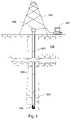
- FIG. 1is a cross-sectional diagram of an embodiment of a drill string suspended in a bore hole.
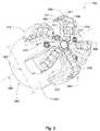
- FIG. 2is a perspective diagram of an embodiment of a drill bit.
- FIG. 3is a perspective diagram of another embodiment of a drill bit.
- FIG. 4is a cross-sectional diagram of another embodiment of a drill bit.
- FIG. 5is a perspective diagram of another embodiment of a drill bit.
- FIG. 6is a perspective diagram of another embodiment of a drill bit.
- FIG. 7is an orthogonal diagram of a working face of drill bit.
- FIG. 8is a perspective cross-sectional diagram of a drill bit.
- FIG. 9is a flowchart illustrating a method of stiffening a drill bit.
- FIG. 1is a cross-sectional diagram of an embodiment of a drill string 100 suspended in a borehole 101 by a derrick 102 .
- a bottom-hole assembly 103is located at the bottom of the borehole 101 and comprises a drill bit 104 .
- the drill string 100may penetrate soft or hard subterranean formations 105 .
- the bottom-hole assembly 103 and/or downhole componentsmay comprise data acquisition devices which may gather data.
- the datamay be sent to the surface via a transmission system to a data swivel 106 .
- the data swivel 106may send the data to surface equipment 107 .
- the surface equipmentmay send data and/or power to downhole tools and/or the bottom-hole assembly 103 .
- U.S. Pat. No. 6,670,880which is herein incorporated by reference for all that it contains, discloses a telemetry system that may be compatible with the present invention; however, other forms of telemetry may also be compatible such as systems that include mud pulse systems, electromagnetic waves, radio waves, and/or short hop. In some embodiments, no telemetry system is incorporated into the drill string. Mud pulse, short hop, or EM telemetry systems may also be used with the present invention.
- the drill bit 104may be a shear bit.
- the bit 104comprises a steel body 201 disposed intermediate a threaded end 202 and a working face 203 .
- a plurality of fixed cutter elements 204is disposed on the working face 203 . These cutter elements 204 degrade the formation when the bit rotates around an axis of rotation 205 .
- the cutter elements 204may be 13 to 19 mm in diameter.
- the bit 104comprises a plurality of steel blades 206 disposed along an outer diameter 207 of the body 201 and extending radially away from the axis of rotation 205 . At least some of the plurality of cutter elements 204 are disposed on the blades 206 .
- Each of the plurality of steel blades 206comprises a steel stiffness and a steel elastic modulus.
- the steel elastic modulusmay be at least 25 million pounds per square inch.
- the steel elastic modulusmay be between 27 and 33 million pounds per square inch.
- the steel stiffnessmay be determined by the elastic modulus of the steel and by the shape of the steel.
- At least one of the plurality of steel blades 206comprises at least one stiffening element 208 .
- a stiffening element 208may comprise an elastic modulus of at least 100 million pounds per square inch.
- the blade 206 comprising a stiffening element 208also comprises an overall stiffness at least 3.5 times greater than the steel stiffness.
- the blade 206may comprise an overall stiffness at least 5 times greater than the steel stiffness. It is believed that the greater stiffness of the steel blade 206 may optimize the impact impulse generated by cutter elements 204 on the formation when the cutter elements 204 contact the formation. This may optimize the rate of penetration (ROP) of the drill bit 104 , while minimizing the cost of the blade 206 . Optimized impact impulse may also reduce wear on the cutter elements 204 or on the bit 104 .
- ROPrate of penetration
- the working face 203comprises five blades 206 , though the working face 203 may comprise any number of blades 206 .
- Each bladecomprises a plurality of cutter elements 204 .
- the cutter elements 204each comprise a cutting surface 209 and may be arrayed along substantially an entire length 210 of a blade 206 .
- the cutting surface 209 of the cutter elements 204preferably comprises a superhard material 211 with a hardness of at least 63 HRc.
- the superhard material 211may comprise diamond, polycrystalline diamond, cubic boron nitride, cobalt, or combinations thereof.
- each blade 206comprises a plurality of stiffening elements 208 .
- the stiffening elements 208may comprise tungsten carbide, other types of cemented metal carbides, or combinations thereof.
- a stiffening element 208may be a backing plate, a bracket, a carbide segment, a carbide rod, or combinations thereof.
- the bit 104may comprise a variety of types of stiffening elements 208 .
- stiffening elements 208are metal carbide segments 216 and each segment 216 comprises a generally cylindrical geometry.
- the segments 216 in the embodiment of FIG. 2are each disposed behind and substantially coaxial with at least one cutter element 204 . Segments 216 may be disposed along substantially the entire length 210 of a blade 206 .
- a segment 216may be brazed together with a cutter element 204 with a high-strength braze 217 .
- the cutter element 204 and the segment 216may then be brazed to the blade 206 .
- only the stiffening element 208may be brazed to the blade 206 .
- Brazing the cutter element 204 to a segment 216may allow for cutter elements 204 to be more shallowly imbedded into the blade 206 than may be common in the art without decreasing the surface area of the blade 206 that is connected to the cutter element 204 directly or indirectly by a braze.
- the blades 206form a plurality of junk slots 212 which converge proximate the axis of rotation 205 on the working face 203 and diverge radially towards a gauge 213 of the bit 104 .
- a jack element 215 coaxial with the axis of rotation 205 of the bit 104may be disposed within and extend from the working face 203 .
- the shape of the working face 203 and the arrangement of the cutter elements 204may be such that as the bit rotates, a raised portion is formed in the formation 105 by a conical portion of the blades.
- the jack element 215compresses the center of the raised portion, creating an indention.
- the indentionmay help stabilize the drill bit 104 and may reduce bit whirl by maintaining the jack element 215 centered about the indention.
- the jack element 215may be a hard, metal insert which may be brazed or press fit into a recess in the working face 203 .
- the hard metalmay comprise a tungsten carbide, niobium carbide, a cemented metal carbide, hardened steel, titanium, tungsten, aluminum, chromium, nickel, or combinations thereof.
- the jack element 215may comprise a surface comprising a hard material with a hardness of at least 63 HRc, which may lengthen the lifetime of the jack element 215 and may aid in compressing harder formations.
- the hard materialmay comprise a polycrystalline diamond, natural diamond, synthetic diamond, vapor deposited diamond, silicon bonded diamond, cobalt bonded diamond, thermally stable diamond, polycrystalline diamond with a binder concentration of 1 to 40 weight percent, infiltrated diamond, layered diamond, polished diamond, course diamond, fine diamond, cubic boron nitride, chromium, titanium, matrix, diamond impregnated matrix, diamond impregnated carbide, a cemented metal carbide, tungsten carbide, niobium, or combinations thereof.
- the jack element 215may oscillate.
- one or more cutter elements 204may be like those disclosed in U.S. patent application Ser. No. 11/734,675 by Hall et al., which is herein incorporated by reference for all that it contains.
- the cutter element 301comprises a sintered body 302 of diamond or diamond-like particles in a metal matrix bonded to a cemented metal carbide substrate 303 at a non-planar interface 304 .
- the sintered body 302comprises a flat working surface 305 .
- At least one region of the working surface 305may be far enough away from the non-planar interface 304 that during high pressure, high temperature (HPHT) processing a restricted amount of metal from the substrate reaches the region, the amount comprising 5 to 0.1 percent of the region by volume, resulting in the region comprising a high density of superhard particles.
- the regionmay comprise the characteristic of being able to withstand an impact of at least 80 joules, and in some embodiments more than 120 joules according to the testing parameters described in U.S. patent application Ser. No. 11/766,975.
- the regionmay be substantially non-electrically conductive.
- the diamond in the sintered body 302may comprise an average particle size of 5 to 60 microns.
- FIG. 3also discloses cutter elements 204 placed on the blade 206 with varying densities at different positions of the blade 206 .
- Adjacent cutter elements 308comprise an intermediate distance 309 .
- the intermediate distance 309 between adjacent cutter elements 308may vary at different positions along the blade 206 .
- adjacent cutter elements 308 disposed on the gauge 213 of the bit 104have a longer intermediate distance 309 than adjacent cutter elements 308 that are disposed near a nose portion 403 of the blade 206 .
- cutter elements 204may each comprise a central axis 306 .
- Adjacent cutter elements 308may be coaxial.
- central axes 306 of adjacent cutter elements 308may be perpendicular or may intersect at an acute or obtuse angle.
- blade 206comprises a gauge portion 401 , a flank portion 402 , a nose portion 403 , and a cone portion 404 .
- Stiffening elements 208may be disposed on the gauge portion, flank portion, nose portion, cone portion, or on combinations thereof. In some embodiments of the invention all portions 401 , 402 , 403 , 404 of the blade 206 may comprise stiffening elements 208 .
- FIG. 4also discloses a stiffening element 208 that is a carbide insert 405 . Carbide inserts 405 may be press fit into a cavity 407 in the steel blade 206 .
- Carbide inserts 405may comprise an outer rounded surface 406 complementary for mating with a generally cylindrical cutter element 204 .
- a cutter element 204may be brazed to the rounded surface 406 of a carbide insert 405 .
- the cutter element 204may also be brazed to the steel blade 206 .
- Blades 206may comprise a plurality of materials that create an overall composite elastic modulus of at least 100 million pounds per square inch.
- the blademay comprise a steel elastic modulus of approximately 29 million pounds per square inch.
- Stiffening elements 208may comprise an elastic modulus much greater than that.
- the overall elastic modulus of the blademay increase to at least 100 million pounds per square inch.
- the overall elastic modulus of the blade 206may be larger than a proportional sum of both the steel elastic modulus and the elastic modulus of the carbide inserts 405 .
- only one portion 401 , 402 , 403 , 404 of the blade 206may comprise an overall composite elastic modulus of at least 100 million pounds per square inch.
- the stiffening element 208may be disposed on a back surface 501 of a blade 206 .
- Back surface 501may be on an end 502 of the blade 206 that is opposite the cutting surface 209 of at least one cutter element 204 .
- a backing plate 503is shown disposed on the back surface 501 .
- the backing plate 503may comprise tungsten carbide and may be brazed to the back surface 501 .
- Backing plate 503may be brazed or press fit into the body 201 of the bit 104 at a base 504 of the blade 206 .
- the backing plate 503may comprise protrusions (not shown) that extend into the blade 206 or the body 201 . Brackets (not shown) may also be disposed adjacent the blade base 504 and may stiffen the blade 206 .
- FIG. 6discloses a bit 104 with steel blades 601 that each comprise a recess 602 .
- a stiffening element 208is disposed within the recess 602 and is attached to the blade 206 .
- the stiffening element 208may comprise tungsten carbide. It may be brazed to the blade 206 at a non-planar interface 603 .
- a plurality of cutter elements 204may be attached to the blade 206 by the stiffening element 208 .
- the cutter elements 204may be brazed to the stiffening element 208 .
- the stiffening element 208is disposed intermediate the cutter elements 204 and the blade 206 .
- a plurality of high pressure jets 605is disposed within the junk slots 212 in the working face 203 .
- a jet 605may be proximate each blade 206 .
- the jets 605may be connected to a bore of the drill bit 104 through fluid pathways formed in the bit body.
- the jets 605may comprise replaceable nozzles disposed within the working face 203 . Fluid may pass through the fluid pathways from the bore and be emitted from the jets 605 at a high velocity. The high velocity fluid may then pass through the junk slots 212 in the working face 203 and gauge 213 of the bit 104 and clear the cuttings away from the working face 203 .
- each blade 206 of FIG. 7comprises a plurality of carbide segments 216 that are brazed to both the blade 206 and to a cutter element 204 .
- the embodiment of FIG. 7also discloses a blade 206 that is narrower at the nose portion 403 than at the gauge portion 401 , hence a shorter carbide segment 216 may be incorporated near the nose portion 403 of the blade 206 .
- a carbide insert 405may be press fit into the blade 206 on the nose portion 403 .
- a cutter element 204may then be brazed to the insert 405 .
- the use of multiple types of stiffening elements 208 on a single blade 206may allow for maximal stiffening of blades 206 despite difficulties posed by various blade geometries.
- a perspective cross-sectional diagramdiscloses a drill bit 104 comprising a channel 801 disposed within a jack element 215 .
- the drill bit 104may comprise a plurality of channels 801 .
- Channel 801 and nozzle 605may both be in fluid communication with a central bore 802 of the tool string 100 .
- Drilling mud(not shown) may be pumped downhole from the surface through the central bore 802 . When the mud reaches the bit 104 much of the mud may pass through nozzles 605 . Small particles of the mud may pass through a filter wall 803 to its inner region 804 and then through one or more channels 801 formed in the jack element 215 , thus preventing large particles from clogging the channels. It is commonly believed that extruding drilling mud as closely as possible to the jack element 215 may increase the efficiency of the drill bit 104 by quickly clearing away drilling debris.
- FIG. 9discloses a method 900 of stiffening a steel blade 206 on a drill bit 104 .
- the method 900comprises a step 901 of providing a drill bit 104 comprising a plurality of steel blades 206 disposed along an outer diameter 207 of a steel body 201 of the bit 104 and a plurality of cutter elements 204 disposed on the plurality of steel blades 206 , wherein each of the plurality of steel blades 206 comprise a steel stiffness and a steel elastic modulus.
- the method 900further comprises a step of increasing an overall stiffness of the blade 206 to at least 3.5 times the steel stiffness by attaching at least one stiffening element 208 to the blade 206 .
Landscapes
- Engineering & Computer Science (AREA)
- Geology (AREA)
- Life Sciences & Earth Sciences (AREA)
- Mining & Mineral Resources (AREA)
- Physics & Mathematics (AREA)
- Environmental & Geological Engineering (AREA)
- Fluid Mechanics (AREA)
- Mechanical Engineering (AREA)
- General Life Sciences & Earth Sciences (AREA)
- Geochemistry & Mineralogy (AREA)
- Chemical & Material Sciences (AREA)
- Crystallography & Structural Chemistry (AREA)
- Earth Drilling (AREA)
Abstract
Description
Claims (10)
Priority Applications (1)
| Application Number | Priority Date | Filing Date | Title |
|---|---|---|---|
| US11/767,044US7571782B2 (en) | 2007-06-22 | 2007-06-22 | Stiffened blade for shear-type drill bit |
Applications Claiming Priority (1)
| Application Number | Priority Date | Filing Date | Title |
|---|---|---|---|
| US11/767,044US7571782B2 (en) | 2007-06-22 | 2007-06-22 | Stiffened blade for shear-type drill bit |
Publications (2)
| Publication Number | Publication Date |
|---|---|
| US20080314645A1 US20080314645A1 (en) | 2008-12-25 |
| US7571782B2true US7571782B2 (en) | 2009-08-11 |
Family
ID=40135302
Family Applications (1)
| Application Number | Title | Priority Date | Filing Date |
|---|---|---|---|
| US11/767,044Expired - Fee RelatedUS7571782B2 (en) | 2007-06-22 | 2007-06-22 | Stiffened blade for shear-type drill bit |
Country Status (1)
| Country | Link |
|---|---|
| US (1) | US7571782B2 (en) |
Cited By (61)
| Publication number | Priority date | Publication date | Assignee | Title |
|---|---|---|---|---|
| US20090158897A1 (en)* | 2005-11-21 | 2009-06-25 | Hall David R | Jack Element with a Stop-off |
| US20100230177A1 (en)* | 2009-03-10 | 2010-09-16 | Baker Hughes Incorporated | Earth-boring tools with thermally conductive regions and related methods |
| US20100230176A1 (en)* | 2009-03-10 | 2010-09-16 | Baker Hughes Incorporated | Earth-boring tools with stiff insert support regions and related methods |
| US20110127087A1 (en)* | 2009-12-01 | 2011-06-02 | Geir Hareland | Pdc drill bit with flute design for better bit cleaning |
| US20120247840A1 (en)* | 2011-03-30 | 2012-10-04 | Baker Hughes Incorporated | Methods of forming earth boring tools and related structures |
| US8281882B2 (en) | 2005-11-21 | 2012-10-09 | Schlumberger Technology Corporation | Jack element for a drill bit |
| US8360174B2 (en) | 2006-03-23 | 2013-01-29 | Schlumberger Technology Corporation | Lead the bit rotary steerable tool |
| US20130092453A1 (en)* | 2011-10-14 | 2013-04-18 | Charles Daniel Johnson | Use of tungsten carbide tube rod to hard-face pdc matrix |
| US8522897B2 (en) | 2005-11-21 | 2013-09-03 | Schlumberger Technology Corporation | Lead the bit rotary steerable tool |
| US8701799B2 (en) | 2009-04-29 | 2014-04-22 | Schlumberger Technology Corporation | Drill bit cutter pocket restitution |
| US8720610B2 (en)* | 2008-11-06 | 2014-05-13 | National Oilwell Varco, L.P. | Resilient bit systems and methods |
| US8925654B2 (en) | 2011-12-08 | 2015-01-06 | Baker Hughes Incorporated | Earth-boring tools and methods of forming earth-boring tools |
| US9518464B2 (en) | 2012-10-19 | 2016-12-13 | The Sollami Company | Combination polycrystalline diamond bit and bit holder |
| US20170211333A1 (en)* | 2014-07-21 | 2017-07-27 | Schlumberger Technology Corporation | Downhole rotary cutting tool |
| US20170211334A1 (en)* | 2014-07-21 | 2017-07-27 | Schlumberger Technology Corporation | Reamer |
| US20170211335A1 (en)* | 2014-07-21 | 2017-07-27 | Schlumberger Technology Corporation | Reamer |
| US20170218707A1 (en)* | 2014-07-21 | 2017-08-03 | Schlumberger Technology Corporation | Reamer |
| US9879531B2 (en) | 2014-02-26 | 2018-01-30 | The Sollami Company | Bit holder shank and differential interference between the shank distal portion and the bit holder block bore |
| US9909416B1 (en) | 2013-09-18 | 2018-03-06 | The Sollami Company | Diamond tipped unitary holder/bit |
| US9976418B2 (en) | 2014-04-02 | 2018-05-22 | The Sollami Company | Bit/holder with enlarged ballistic tip insert |
| US9988903B2 (en) | 2012-10-19 | 2018-06-05 | The Sollami Company | Combination polycrystalline diamond bit and bit holder |
| US10047565B2 (en)* | 2012-02-03 | 2018-08-14 | Baker Hughes Incorporated | Cutting element retention for high exposure cutting elements on earth-boring tools |
| US10072501B2 (en) | 2010-08-27 | 2018-09-11 | The Sollami Company | Bit holder |
| US10107097B1 (en) | 2012-10-19 | 2018-10-23 | The Sollami Company | Combination polycrystalline diamond bit and bit holder |
| US10105870B1 (en) | 2012-10-19 | 2018-10-23 | The Sollami Company | Combination polycrystalline diamond bit and bit holder |
| US10107098B2 (en) | 2016-03-15 | 2018-10-23 | The Sollami Company | Bore wear compensating bit holder and bit holder block |
| US10180065B1 (en) | 2015-10-05 | 2019-01-15 | The Sollami Company | Material removing tool for road milling mining and trenching operations |
| US10260342B1 (en) | 2012-10-19 | 2019-04-16 | The Sollami Company | Combination polycrystalline diamond bit and bit holder |
| US10323515B1 (en) | 2012-10-19 | 2019-06-18 | The Sollami Company | Tool with steel sleeve member |
| US10337324B2 (en) | 2015-01-07 | 2019-07-02 | The Sollami Company | Various bit holders and unitary bit/holders for use with shortened depth bit holder blocks |
| US10370966B1 (en) | 2014-04-23 | 2019-08-06 | The Sollami Company | Rear of base block |
| US10385689B1 (en) | 2010-08-27 | 2019-08-20 | The Sollami Company | Bit holder |
| US10415386B1 (en) | 2013-09-18 | 2019-09-17 | The Sollami Company | Insertion-removal tool for holder/bit |
| US10502056B2 (en) | 2015-09-30 | 2019-12-10 | The Sollami Company | Reverse taper shanks and complementary base block bores for bit assemblies |
| US10508499B2 (en)* | 2014-07-21 | 2019-12-17 | Schlumberger Technology Corporation | Reamer |
| US10577931B2 (en) | 2016-03-05 | 2020-03-03 | The Sollami Company | Bit holder (pick) with shortened shank and angular differential between the shank and base block bore |
| US10598013B2 (en) | 2010-08-27 | 2020-03-24 | The Sollami Company | Bit holder with shortened nose portion |
| US10612375B2 (en) | 2016-04-01 | 2020-04-07 | The Sollami Company | Bit retainer |
| US10612376B1 (en) | 2016-03-15 | 2020-04-07 | The Sollami Company | Bore wear compensating retainer and washer |
| US10633971B2 (en) | 2016-03-07 | 2020-04-28 | The Sollami Company | Bit holder with enlarged tire portion and narrowed bit holder block |
| US10767478B2 (en) | 2013-09-18 | 2020-09-08 | The Sollami Company | Diamond tipped unitary holder/bit |
| US10794181B2 (en) | 2014-04-02 | 2020-10-06 | The Sollami Company | Bit/holder with enlarged ballistic tip insert |
| US10876402B2 (en) | 2014-04-02 | 2020-12-29 | The Sollami Company | Bit tip insert |
| US10876401B1 (en) | 2016-07-26 | 2020-12-29 | The Sollami Company | Rotational style tool bit assembly |
| US10947844B1 (en) | 2013-09-18 | 2021-03-16 | The Sollami Company | Diamond Tipped Unitary Holder/Bit |
| US10968739B1 (en) | 2013-09-18 | 2021-04-06 | The Sollami Company | Diamond tipped unitary holder/bit |
| US10968738B1 (en) | 2017-03-24 | 2021-04-06 | The Sollami Company | Remanufactured conical bit |
| US10995613B1 (en) | 2013-09-18 | 2021-05-04 | The Sollami Company | Diamond tipped unitary holder/bit |
| US11103939B2 (en) | 2018-07-18 | 2021-08-31 | The Sollami Company | Rotatable bit cartridge |
| US11168563B1 (en) | 2013-10-16 | 2021-11-09 | The Sollami Company | Bit holder with differential interference |
| US11187080B2 (en) | 2018-04-24 | 2021-11-30 | The Sollami Company | Conical bit with diamond insert |
| WO2022035452A1 (en)* | 2020-08-12 | 2022-02-17 | Saudi Arabian Oil Company | Rotatable multi-head ball bits |
| US11261731B1 (en) | 2014-04-23 | 2022-03-01 | The Sollami Company | Bit holder and unitary bit/holder for use in shortened depth base blocks |
| US11279012B1 (en) | 2017-09-15 | 2022-03-22 | The Sollami Company | Retainer insertion and extraction tool |
| US11339656B1 (en) | 2014-02-26 | 2022-05-24 | The Sollami Company | Rear of base block |
| US11339654B2 (en) | 2014-04-02 | 2022-05-24 | The Sollami Company | Insert with heat transfer bore |
| US11591857B2 (en)* | 2017-05-31 | 2023-02-28 | Schlumberger Technology Corporation | Cutting tool with pre-formed hardfacing segments |
| US11891895B1 (en) | 2014-04-23 | 2024-02-06 | The Sollami Company | Bit holder with annular rings |
| US12018556B2 (en) | 2018-08-29 | 2024-06-25 | Schlumberger Technology Corporation | Systems and methods of controlling downhole behavior |
| US12031386B2 (en) | 2020-08-27 | 2024-07-09 | Schlumberger Technology Corporation | Blade cover |
| US12345158B1 (en) | 2019-06-20 | 2025-07-01 | The Sollami Company | Bit tip insert |
Families Citing this family (9)
| Publication number | Priority date | Publication date | Assignee | Title |
|---|---|---|---|---|
| WO2009058808A1 (en)* | 2007-10-29 | 2009-05-07 | Baker Hughes Incorporated | Drill bits and tools for subterranean drilling |
| US8079430B2 (en)* | 2009-04-22 | 2011-12-20 | Baker Hughes Incorporated | Drill bits and tools for subterranean drilling, methods of manufacturing such drill bits and tools and methods of off-center drilling |
| US8459357B2 (en)* | 2009-05-04 | 2013-06-11 | Smith International, Inc. | Milling system and method of milling |
| BE1019132A3 (en)* | 2010-01-05 | 2012-03-06 | Diamant Drilling Services S A | ROTARY TREPAN AND METHOD FOR MANUFACTURING THE SAME |
| GB2520998B (en) | 2013-12-06 | 2016-06-29 | Schlumberger Holdings | Expandable Reamer |
| WO2016014283A1 (en) | 2014-07-21 | 2016-01-28 | Schlumberger Canada Limited | Reamer |
| CN107109903A (en)* | 2015-03-05 | 2017-08-29 | 哈利伯顿能源服务公司 | Macroscopical drill bit reinforcer |
| US10357776B2 (en)* | 2016-09-09 | 2019-07-23 | Comcorp, Inc. | Impact cutter blade and holder system and method |
| CN108612480B (en)* | 2018-06-29 | 2024-06-18 | 中国石油天然气集团有限公司 | Vortex pulse impact drill bit |
Citations (21)
| Publication number | Priority date | Publication date | Assignee | Title |
|---|---|---|---|---|
| US4109737A (en) | 1976-06-24 | 1978-08-29 | General Electric Company | Rotary drill bit |
| US4499958A (en)* | 1983-04-29 | 1985-02-19 | Strata Bit Corporation | Drag blade bit with diamond cutting elements |
| US5101692A (en) | 1989-09-16 | 1992-04-07 | Astec Developments Limited | Drill bit or corehead manufacturing process |
| US5333699A (en) | 1992-12-23 | 1994-08-02 | Baroid Technology, Inc. | Drill bit having polycrystalline diamond compact cutter with spherical first end opposite cutting end |
| US5435403A (en) | 1993-12-09 | 1995-07-25 | Baker Hughes Incorporated | Cutting elements with enhanced stiffness and arrangements thereof on earth boring drill bits |
| US5441121A (en) | 1993-12-22 | 1995-08-15 | Baker Hughes, Inc. | Earth boring drill bit with shell supporting an external drilling surface |
| US5449048A (en) | 1992-12-23 | 1995-09-12 | Baroid Technology, Inc. | Drill bit having chip breaker polycrystalline diamond compact and hard metal insert at gauge surface |
| US5558170A (en) | 1992-12-23 | 1996-09-24 | Baroid Technology, Inc. | Method and apparatus for improving drill bit stability |
| US5560440A (en) | 1993-02-12 | 1996-10-01 | Baker Hughes Incorporated | Bit for subterranean drilling fabricated from separately-formed major components |
| US5848657A (en) | 1996-12-27 | 1998-12-15 | General Electric Company | Polycrystalline diamond cutting element |
| US6021859A (en) | 1993-12-09 | 2000-02-08 | Baker Hughes Incorporated | Stress related placement of engineered superabrasive cutting elements on rotary drag bits |
| US20010004946A1 (en)* | 1997-11-28 | 2001-06-28 | Kenneth M. Jensen | Enhanced non-planar drill insert |
| US6302224B1 (en) | 1999-05-13 | 2001-10-16 | Halliburton Energy Services, Inc. | Drag-bit drilling with multi-axial tooth inserts |
| US6332503B1 (en) | 1992-01-31 | 2001-12-25 | Baker Hughes Incorporated | Fixed cutter bit with chisel or vertical cutting elements |
| US6408959B2 (en) | 1998-09-18 | 2002-06-25 | Kenneth E. Bertagnolli | Polycrystalline diamond compact cutter having a stress mitigating hoop at the periphery |
| US6408958B1 (en) | 2000-10-23 | 2002-06-25 | Baker Hughes Incorporated | Superabrasive cutting assemblies including cutters of varying orientations and drill bits so equipped |
| US6484826B1 (en) | 1998-02-13 | 2002-11-26 | Smith International, Inc. | Engineered enhanced inserts for rock drilling bits |
| US6651756B1 (en) | 2000-11-17 | 2003-11-25 | Baker Hughes Incorporated | Steel body drill bits with tailored hardfacing structural elements |
| US6672406B2 (en) | 1997-09-08 | 2004-01-06 | Baker Hughes Incorporated | Multi-aggressiveness cuttting face on PDC cutters and method of drilling subterranean formations |
| US20050103533A1 (en)* | 2003-11-17 | 2005-05-19 | Sherwood William H.Jr. | Cutting element retention apparatus for use in steel body rotary drill bits, steel body rotary drill bits so equipped, and method of manufacture and repair therefor |
| US20070251732A1 (en)* | 2006-04-27 | 2007-11-01 | Tdy Industries, Inc. | Modular Fixed Cutter Earth-Boring Bits, Modular Fixed Cutter Earth-Boring Bit Bodies, and Related Methods |
Family Cites Families (1)
| Publication number | Priority date | Publication date | Assignee | Title |
|---|---|---|---|---|
| US5333599A (en)* | 1993-07-13 | 1994-08-02 | Jang Sun Sing | External body of smoke exhauster |
- 2007
- 2007-06-22USUS11/767,044patent/US7571782B2/ennot_activeExpired - Fee Related
Patent Citations (23)
| Publication number | Priority date | Publication date | Assignee | Title |
|---|---|---|---|---|
| US4109737A (en) | 1976-06-24 | 1978-08-29 | General Electric Company | Rotary drill bit |
| US4499958A (en)* | 1983-04-29 | 1985-02-19 | Strata Bit Corporation | Drag blade bit with diamond cutting elements |
| US5101692A (en) | 1989-09-16 | 1992-04-07 | Astec Developments Limited | Drill bit or corehead manufacturing process |
| US6332503B1 (en) | 1992-01-31 | 2001-12-25 | Baker Hughes Incorporated | Fixed cutter bit with chisel or vertical cutting elements |
| US5333699A (en) | 1992-12-23 | 1994-08-02 | Baroid Technology, Inc. | Drill bit having polycrystalline diamond compact cutter with spherical first end opposite cutting end |
| US5449048A (en) | 1992-12-23 | 1995-09-12 | Baroid Technology, Inc. | Drill bit having chip breaker polycrystalline diamond compact and hard metal insert at gauge surface |
| US5558170A (en) | 1992-12-23 | 1996-09-24 | Baroid Technology, Inc. | Method and apparatus for improving drill bit stability |
| US5560440A (en) | 1993-02-12 | 1996-10-01 | Baker Hughes Incorporated | Bit for subterranean drilling fabricated from separately-formed major components |
| US6021859A (en) | 1993-12-09 | 2000-02-08 | Baker Hughes Incorporated | Stress related placement of engineered superabrasive cutting elements on rotary drag bits |
| US5435403A (en) | 1993-12-09 | 1995-07-25 | Baker Hughes Incorporated | Cutting elements with enhanced stiffness and arrangements thereof on earth boring drill bits |
| US5441121A (en) | 1993-12-22 | 1995-08-15 | Baker Hughes, Inc. | Earth boring drill bit with shell supporting an external drilling surface |
| US5848657A (en) | 1996-12-27 | 1998-12-15 | General Electric Company | Polycrystalline diamond cutting element |
| US6672406B2 (en) | 1997-09-08 | 2004-01-06 | Baker Hughes Incorporated | Multi-aggressiveness cuttting face on PDC cutters and method of drilling subterranean formations |
| US20010004946A1 (en)* | 1997-11-28 | 2001-06-28 | Kenneth M. Jensen | Enhanced non-planar drill insert |
| US6484826B1 (en) | 1998-02-13 | 2002-11-26 | Smith International, Inc. | Engineered enhanced inserts for rock drilling bits |
| US6408959B2 (en) | 1998-09-18 | 2002-06-25 | Kenneth E. Bertagnolli | Polycrystalline diamond compact cutter having a stress mitigating hoop at the periphery |
| US6302224B1 (en) | 1999-05-13 | 2001-10-16 | Halliburton Energy Services, Inc. | Drag-bit drilling with multi-axial tooth inserts |
| US6408958B1 (en) | 2000-10-23 | 2002-06-25 | Baker Hughes Incorporated | Superabrasive cutting assemblies including cutters of varying orientations and drill bits so equipped |
| US6651756B1 (en) | 2000-11-17 | 2003-11-25 | Baker Hughes Incorporated | Steel body drill bits with tailored hardfacing structural elements |
| US20050103533A1 (en)* | 2003-11-17 | 2005-05-19 | Sherwood William H.Jr. | Cutting element retention apparatus for use in steel body rotary drill bits, steel body rotary drill bits so equipped, and method of manufacture and repair therefor |
| US7070011B2 (en) | 2003-11-17 | 2006-07-04 | Baker Hughes Incorporated | Steel body rotary drill bits including support elements affixed to the bit body at least partially defining cutter pocket recesses |
| US7216565B2 (en) | 2003-11-17 | 2007-05-15 | Baker Hughes Incorporated | Methods of manufacturing and repairing steel body rotary drill bits including support elements affixed to the bit body at least partially defining cutter pocket recesses |
| US20070251732A1 (en)* | 2006-04-27 | 2007-11-01 | Tdy Industries, Inc. | Modular Fixed Cutter Earth-Boring Bits, Modular Fixed Cutter Earth-Boring Bit Bodies, and Related Methods |
Cited By (77)
| Publication number | Priority date | Publication date | Assignee | Title |
|---|---|---|---|---|
| US8522897B2 (en) | 2005-11-21 | 2013-09-03 | Schlumberger Technology Corporation | Lead the bit rotary steerable tool |
| US20090158897A1 (en)* | 2005-11-21 | 2009-06-25 | Hall David R | Jack Element with a Stop-off |
| US8020471B2 (en)* | 2005-11-21 | 2011-09-20 | Schlumberger Technology Corporation | Method for manufacturing a drill bit |
| US8281882B2 (en) | 2005-11-21 | 2012-10-09 | Schlumberger Technology Corporation | Jack element for a drill bit |
| US8360174B2 (en) | 2006-03-23 | 2013-01-29 | Schlumberger Technology Corporation | Lead the bit rotary steerable tool |
| US8720610B2 (en)* | 2008-11-06 | 2014-05-13 | National Oilwell Varco, L.P. | Resilient bit systems and methods |
| US20100230177A1 (en)* | 2009-03-10 | 2010-09-16 | Baker Hughes Incorporated | Earth-boring tools with thermally conductive regions and related methods |
| US20100230176A1 (en)* | 2009-03-10 | 2010-09-16 | Baker Hughes Incorporated | Earth-boring tools with stiff insert support regions and related methods |
| US8701799B2 (en) | 2009-04-29 | 2014-04-22 | Schlumberger Technology Corporation | Drill bit cutter pocket restitution |
| US20110127087A1 (en)* | 2009-12-01 | 2011-06-02 | Geir Hareland | Pdc drill bit with flute design for better bit cleaning |
| US8517124B2 (en) | 2009-12-01 | 2013-08-27 | Northbasin Energy Services Inc. | PDC drill bit with flute design for better bit cleaning |
| US8899355B2 (en) | 2009-12-01 | 2014-12-02 | Northbasin Energy Services Inc. | PDC drill bit with flute design for better bit cleaning |
| US10072501B2 (en) | 2010-08-27 | 2018-09-11 | The Sollami Company | Bit holder |
| US10385689B1 (en) | 2010-08-27 | 2019-08-20 | The Sollami Company | Bit holder |
| US10598013B2 (en) | 2010-08-27 | 2020-03-24 | The Sollami Company | Bit holder with shortened nose portion |
| US9579717B2 (en) | 2011-03-30 | 2017-02-28 | Baker Hughes Incorporated | Methods of forming earth-boring tools including blade frame segments |
| US20120247840A1 (en)* | 2011-03-30 | 2012-10-04 | Baker Hughes Incorporated | Methods of forming earth boring tools and related structures |
| US9068408B2 (en)* | 2011-03-30 | 2015-06-30 | Baker Hughes Incorporated | Methods of forming earth-boring tools and related structures |
| US9435158B2 (en)* | 2011-10-14 | 2016-09-06 | Varel International Ind., L.P | Use of tungsten carbide tube rod to hard-face PDC matrix |
| US20130092453A1 (en)* | 2011-10-14 | 2013-04-18 | Charles Daniel Johnson | Use of tungsten carbide tube rod to hard-face pdc matrix |
| US9810026B2 (en) | 2011-12-08 | 2017-11-07 | Baker Hughes Incorporated | Earth-boring tools and methods of forming earth-boring tools |
| US8925654B2 (en) | 2011-12-08 | 2015-01-06 | Baker Hughes Incorporated | Earth-boring tools and methods of forming earth-boring tools |
| US10047565B2 (en)* | 2012-02-03 | 2018-08-14 | Baker Hughes Incorporated | Cutting element retention for high exposure cutting elements on earth-boring tools |
| US10105870B1 (en) | 2012-10-19 | 2018-10-23 | The Sollami Company | Combination polycrystalline diamond bit and bit holder |
| US9988903B2 (en) | 2012-10-19 | 2018-06-05 | The Sollami Company | Combination polycrystalline diamond bit and bit holder |
| US10746021B1 (en) | 2012-10-19 | 2020-08-18 | The Sollami Company | Combination polycrystalline diamond bit and bit holder |
| US10107097B1 (en) | 2012-10-19 | 2018-10-23 | The Sollami Company | Combination polycrystalline diamond bit and bit holder |
| US9518464B2 (en) | 2012-10-19 | 2016-12-13 | The Sollami Company | Combination polycrystalline diamond bit and bit holder |
| US10260342B1 (en) | 2012-10-19 | 2019-04-16 | The Sollami Company | Combination polycrystalline diamond bit and bit holder |
| US10323515B1 (en) | 2012-10-19 | 2019-06-18 | The Sollami Company | Tool with steel sleeve member |
| US10947844B1 (en) | 2013-09-18 | 2021-03-16 | The Sollami Company | Diamond Tipped Unitary Holder/Bit |
| US9909416B1 (en) | 2013-09-18 | 2018-03-06 | The Sollami Company | Diamond tipped unitary holder/bit |
| US10968739B1 (en) | 2013-09-18 | 2021-04-06 | The Sollami Company | Diamond tipped unitary holder/bit |
| US10767478B2 (en) | 2013-09-18 | 2020-09-08 | The Sollami Company | Diamond tipped unitary holder/bit |
| US10995613B1 (en) | 2013-09-18 | 2021-05-04 | The Sollami Company | Diamond tipped unitary holder/bit |
| US10415386B1 (en) | 2013-09-18 | 2019-09-17 | The Sollami Company | Insertion-removal tool for holder/bit |
| US11168563B1 (en) | 2013-10-16 | 2021-11-09 | The Sollami Company | Bit holder with differential interference |
| US10683752B2 (en) | 2014-02-26 | 2020-06-16 | The Sollami Company | Bit holder shank and differential interference between the shank distal portion and the bit holder block bore |
| US9879531B2 (en) | 2014-02-26 | 2018-01-30 | The Sollami Company | Bit holder shank and differential interference between the shank distal portion and the bit holder block bore |
| US11339656B1 (en) | 2014-02-26 | 2022-05-24 | The Sollami Company | Rear of base block |
| US9976418B2 (en) | 2014-04-02 | 2018-05-22 | The Sollami Company | Bit/holder with enlarged ballistic tip insert |
| US10876402B2 (en) | 2014-04-02 | 2020-12-29 | The Sollami Company | Bit tip insert |
| US10794181B2 (en) | 2014-04-02 | 2020-10-06 | The Sollami Company | Bit/holder with enlarged ballistic tip insert |
| US11339654B2 (en) | 2014-04-02 | 2022-05-24 | The Sollami Company | Insert with heat transfer bore |
| US10370966B1 (en) | 2014-04-23 | 2019-08-06 | The Sollami Company | Rear of base block |
| US11261731B1 (en) | 2014-04-23 | 2022-03-01 | The Sollami Company | Bit holder and unitary bit/holder for use in shortened depth base blocks |
| US11891895B1 (en) | 2014-04-23 | 2024-02-06 | The Sollami Company | Bit holder with annular rings |
| US20170211333A1 (en)* | 2014-07-21 | 2017-07-27 | Schlumberger Technology Corporation | Downhole rotary cutting tool |
| US20170211335A1 (en)* | 2014-07-21 | 2017-07-27 | Schlumberger Technology Corporation | Reamer |
| US20170211334A1 (en)* | 2014-07-21 | 2017-07-27 | Schlumberger Technology Corporation | Reamer |
| US20170218707A1 (en)* | 2014-07-21 | 2017-08-03 | Schlumberger Technology Corporation | Reamer |
| US10704332B2 (en)* | 2014-07-21 | 2020-07-07 | Schlumberger Technology Corporation | Downhole rotary cutting tool |
| US10612309B2 (en)* | 2014-07-21 | 2020-04-07 | Schlumberger Technology Corporation | Reamer |
| US10584538B2 (en)* | 2014-07-21 | 2020-03-10 | Schlumberger Technology Corporation | Reamer |
| US10501995B2 (en)* | 2014-07-21 | 2019-12-10 | Schlumberger Technology Corporation | Reamer |
| US10508499B2 (en)* | 2014-07-21 | 2019-12-17 | Schlumberger Technology Corporation | Reamer |
| US10337324B2 (en) | 2015-01-07 | 2019-07-02 | The Sollami Company | Various bit holders and unitary bit/holders for use with shortened depth bit holder blocks |
| US10502056B2 (en) | 2015-09-30 | 2019-12-10 | The Sollami Company | Reverse taper shanks and complementary base block bores for bit assemblies |
| US10180065B1 (en) | 2015-10-05 | 2019-01-15 | The Sollami Company | Material removing tool for road milling mining and trenching operations |
| US10577931B2 (en) | 2016-03-05 | 2020-03-03 | The Sollami Company | Bit holder (pick) with shortened shank and angular differential between the shank and base block bore |
| US10954785B2 (en) | 2016-03-07 | 2021-03-23 | The Sollami Company | Bit holder with enlarged tire portion and narrowed bit holder block |
| US10633971B2 (en) | 2016-03-07 | 2020-04-28 | The Sollami Company | Bit holder with enlarged tire portion and narrowed bit holder block |
| US10107098B2 (en) | 2016-03-15 | 2018-10-23 | The Sollami Company | Bore wear compensating bit holder and bit holder block |
| US10612376B1 (en) | 2016-03-15 | 2020-04-07 | The Sollami Company | Bore wear compensating retainer and washer |
| US10612375B2 (en) | 2016-04-01 | 2020-04-07 | The Sollami Company | Bit retainer |
| US10876401B1 (en) | 2016-07-26 | 2020-12-29 | The Sollami Company | Rotational style tool bit assembly |
| US10968738B1 (en) | 2017-03-24 | 2021-04-06 | The Sollami Company | Remanufactured conical bit |
| US11591857B2 (en)* | 2017-05-31 | 2023-02-28 | Schlumberger Technology Corporation | Cutting tool with pre-formed hardfacing segments |
| US12241312B2 (en) | 2017-05-31 | 2025-03-04 | Schlumberger Technology Corporation | Cutting tool with pre-formed segment |
| US11279012B1 (en) | 2017-09-15 | 2022-03-22 | The Sollami Company | Retainer insertion and extraction tool |
| US11187080B2 (en) | 2018-04-24 | 2021-11-30 | The Sollami Company | Conical bit with diamond insert |
| US11103939B2 (en) | 2018-07-18 | 2021-08-31 | The Sollami Company | Rotatable bit cartridge |
| US12018556B2 (en) | 2018-08-29 | 2024-06-25 | Schlumberger Technology Corporation | Systems and methods of controlling downhole behavior |
| US12345158B1 (en) | 2019-06-20 | 2025-07-01 | The Sollami Company | Bit tip insert |
| WO2022035452A1 (en)* | 2020-08-12 | 2022-02-17 | Saudi Arabian Oil Company | Rotatable multi-head ball bits |
| US11608689B2 (en) | 2020-08-12 | 2023-03-21 | Saudi Arabian Oil Company | Rotatable multi-head ball bits |
| US12031386B2 (en) | 2020-08-27 | 2024-07-09 | Schlumberger Technology Corporation | Blade cover |
Also Published As
| Publication number | Publication date |
|---|---|
| US20080314645A1 (en) | 2008-12-25 |
Similar Documents
| Publication | Publication Date | Title |
|---|---|---|
| US7571782B2 (en) | Stiffened blade for shear-type drill bit | |
| US7527110B2 (en) | Percussive drill bit | |
| US7533737B2 (en) | Jet arrangement for a downhole drill bit | |
| US6009963A (en) | Superabrasive cutting element with enhanced stiffness, thermal conductivity and cutting efficiency | |
| US10378288B2 (en) | Downhole drill bit incorporating cutting elements of different geometries | |
| US9915102B2 (en) | Pointed working ends on a bit | |
| US7641002B2 (en) | Drill bit | |
| US9322219B2 (en) | Rolling cutter using pin, ball or extrusion on the bit body as attachment methods | |
| US7753144B2 (en) | Drill bit with a retained jack element | |
| US8434573B2 (en) | Degradation assembly | |
| US7963617B2 (en) | Degradation assembly | |
| US20080035387A1 (en) | Downhole Drill Bit | |
| US5303785A (en) | Diamond back-up for PDC cutters | |
| EP0687799A1 (en) | Improvements in or relating to elements faced with superhard material | |
| US7506706B2 (en) | Retaining element for a jack element | |
| US20080035380A1 (en) | Pointed Diamond Working Ends on a Shear Bit | |
| US9038752B2 (en) | Rotary drag bit | |
| WO2015013354A1 (en) | Cutter support element | |
| US20200362640A1 (en) | Drill bit with cutting gauge pad | |
| US10900292B2 (en) | Fixed cutter drill bit having high exposure cutters for increased depth of cut | |
| WO2024151715A1 (en) | Cutters with reduced chamfer angle |
Legal Events
| Date | Code | Title | Description |
|---|---|---|---|
| AS | Assignment | Owner name:HALL, DAVID R., MR., UTAH Free format text:ASSIGNMENT OF ASSIGNORS INTEREST;ASSIGNOR:BAILEY, JOHN, MR.;REEL/FRAME:019469/0466 Effective date:20070622 | |
| STCF | Information on status: patent grant | Free format text:PATENTED CASE | |
| FEPP | Fee payment procedure | Free format text:PAT HOLDER NO LONGER CLAIMS SMALL ENTITY STATUS, ENTITY STATUS SET TO UNDISCOUNTED (ORIGINAL EVENT CODE: STOL); ENTITY STATUS OF PATENT OWNER: LARGE ENTITY | |
| AS | Assignment | Owner name:SCHLUMBERGER TECHNOLOGY CORPORATION,TEXAS Free format text:ASSIGNMENT OF ASSIGNORS INTEREST;ASSIGNOR:HALL, DAVID R., MR.;REEL/FRAME:023973/0849 Effective date:20100122 Owner name:SCHLUMBERGER TECHNOLOGY CORPORATION, TEXAS Free format text:ASSIGNMENT OF ASSIGNORS INTEREST;ASSIGNOR:HALL, DAVID R., MR.;REEL/FRAME:023973/0849 Effective date:20100122 | |
| FPAY | Fee payment | Year of fee payment:4 | |
| FPAY | Fee payment | Year of fee payment:8 | |
| FEPP | Fee payment procedure | Free format text:MAINTENANCE FEE REMINDER MAILED (ORIGINAL EVENT CODE: REM.); ENTITY STATUS OF PATENT OWNER: LARGE ENTITY | |
| LAPS | Lapse for failure to pay maintenance fees | Free format text:PATENT EXPIRED FOR FAILURE TO PAY MAINTENANCE FEES (ORIGINAL EVENT CODE: EXP.); ENTITY STATUS OF PATENT OWNER: LARGE ENTITY | |
| STCH | Information on status: patent discontinuation | Free format text:PATENT EXPIRED DUE TO NONPAYMENT OF MAINTENANCE FEES UNDER 37 CFR 1.362 | |
| FP | Lapsed due to failure to pay maintenance fee | Effective date:20210811 |