US7571392B2 - User definable task based interface - Google Patents
User definable task based interfaceDownload PDFInfo
- Publication number
- US7571392B2 US7571392B2US11/429,431US42943106AUS7571392B2US 7571392 B2US7571392 B2US 7571392B2US 42943106 AUS42943106 AUS 42943106AUS 7571392 B2US7571392 B2US 7571392B2
- Authority
- US
- United States
- Prior art keywords
- task
- tools
- user
- user interface
- file
- Prior art date
- Legal status (The legal status is an assumption and is not a legal conclusion. Google has not performed a legal analysis and makes no representation as to the accuracy of the status listed.)
- Expired - Lifetime, expires
Links
Images


Classifications
- G—PHYSICS
- G06—COMPUTING OR CALCULATING; COUNTING
- G06F—ELECTRIC DIGITAL DATA PROCESSING
- G06F30/00—Computer-aided design [CAD]
- G—PHYSICS
- G06—COMPUTING OR CALCULATING; COUNTING
- G06F—ELECTRIC DIGITAL DATA PROCESSING
- G06F2111/00—Details relating to CAD techniques
- G06F2111/02—CAD in a network environment, e.g. collaborative CAD or distributed simulation
Definitions
- the present inventionrelates generally to systems and methods for customizing user interfaces of software programs and more particularly for providing user customization based on tasks.
- CADComputer-aided design
- CAD softwareincludes an API to access the large quantities of data.
- Applicationssuch as, e.g., MicroStation® products, which are developed by Bentley Systems, Inc., Exton, Pa. U.S.A., and AutoCAD® products, which are developed by Autodesk, Inc., San Rafael, Calif., U.S.A. are typical of such CAD software, which may be used in the Engineering, Construction, and Operations (ECO) marketplace.
- GUIsgraphical user interfaces
- Existing GUIsare similar to those of common office productivity software, such as word-processing programs, in that they provide a large central window showing whatever is being worked on, surrounded by pull-down menus and tool icons.
- GUIsgraphical user interfaces
- Such functionality controlsoften include selectable buttons with such names as “file,” “edit,” “view,” “insert,” “format,” and the like.
- selection of one of these top-level functionality buttonsfor example “format,” causes a drop-down menu to be deployed to expose one or more selectable functionality controls associated with the top-level functionality, for example “font” under a top-level functionality of “format.”
- the drop-down menutypically disappears. If the user determines that functionality of the first drop-down menu was the desired functionality, the user must remember which top-level functionality was selected, reselect that functionality and then find the desired functionality control all over again. Accordingly, in order to use the functionality of a given software application, the user must know the desired functionality is available under one of the selectable buttons, or the user must select different top-level functionalities until the desired specific functionality is located.
- a usermay be performing a task that requires many different types of tools provided by the software program.
- the tools used in completing the taskmay not be generally related to each other, except for being used to perform the task.
- a taskmay require one tool in the “insert” category and another tool in the “format” category. Therefore, the user must search in different categories for the various tools needed to accomplish the task.
- a method of distributing data used in creating CAD design filescomprises receiving input defining attributes of elements to be used in a CAD design file; storing the predefined attributes in a resource library at a central location; attaching the resource library to the design file; presenting a graphical user interface (GUI) displaying the contents of the resource library to a user; receiving input from the user selecting contents of the resource library; associating the selected contents with the element being created; and applying the attributes of the selected contents to the element being created.
- GUIgraphical user interface
- a method of distributing data used in creating CAD design filescomprises: receiving input defining a task to be used in creating or editing a CAD design file; storing the task as part of a user interface definition in a library at a central location; attaching the library to the design file; and presenting a graphical user interface (GUI) displaying the contents of the resource library to a user.
- GUIgraphical user interface
- a method of customizing a user interfacecomprises: presenting a listing of software tools provided by a software program to a user; receiving user input placing selected tools in a task; associating the selected tools with the respective task; storing the association in the task; storing the task in a first format in a library at a central location; associating the task with a file in the first format; and presenting a user interface including tasks from the library associated with the file when the file is opened using the software program.
- a methodcomprises: presenting a user a set of software tools used in a software program; receiving user input defining a task; storing the task definition as part of a user interface definition in a library accessible to multiple users; receiving input associating the library with a file; creating a user interface for the software program based at least in part on the user interface definition from the library when the associated file is opened.
- a computer useable information storage mediumstores computer readable program code for causing a computer to perform the steps of: providing an administrator function allowing the creation of a library defining user interface data including tasks to be applied to a CAD design file; storing the library at a central location; and applying the selected user interface data the software program at runtime.
- a systemcomprises: a software program including a plurality of tools for editing regular data files, the regular data files having format; a library storing a user interface definition including a task, the library being associated with at least one regular data file and having the same format as the regular data file and being editable using the tools; a user interface for the software program that includes the tasks in the library when the associated file is opened.
- FIG. 1is a flow diagram of a method according to an embodiment of the invention
- FIG. 2is a diagram of user interface according to an embodiment of the invention.
- FIG. 3is a diagram of user interface according to an embodiment of the invention.
- FIG. 4is a diagram of user interface according to an embodiment of the invention.
- a system and method providing a user definable task based interfaceis described.
- a software programtypically includes a number of tools.
- the toolsmay be utilized to perform operations on data, such as creating or editing a file using the software program.
- a user of the software programmay organize the tools into tasks, based on the what the tools are used for.
- a taskmay be defined as a set of tools grouped to facilitate a particular work item.
- the task and associated toolsare then presented together in the user interface.
- the userthus may have quick and easy access to the tools needed to complete a task.
- a taskmay be to “draw a foundation.”
- the tools necessary for drawing a foundationmay include measuring, drawing boundaries, etc.
- the tools for these steps in drawing the foundationmay be grouped together into a task.
- the task and associated toolsmay then presented to a user via a user interface for the software program.
- a user interface for the software programFor example, an icon representing the task “draw a foundation” may be presented in the user interface. The user may select the icon or the name of the task and be presented with the tools necessary to accomplish the task.
- Users of the software programmay be given the ability to customize the user interface and define the tasks and tools presented in the user interface.
- the definitionsmay be stored in a central location and be used by multiples users and files.
- FIG. 1illustrates a flow chart of an exemplary method of customizing a task based user interface according to an embodiment of the invention.
- a software programsuch as a CAD program, modeling program etc., provides a number of different tools. The tools are used to manipulate data stored in regular data files having a format used by the software program. The user may group together the tools needed to perform a particular task. The task and associated tools are included in the user interface.
- a listing of software tools available in the software programmay be presented to a user, step 10 . Some or all of the tools available in the software program may be presented. The user may select the tools necessary to perform a task, User input associating the selected tools with a task is received by the system, step 12 .
- the selected toolsare associated with the appropriate task and this information is stored, steps 14 - 16 .
- the informationmay be stored as part of a user interface definition file storing a definition for the user interface.
- the user interface definition filemay have the same format as the regular data file.
- the taskmay be associated with a particular regular data file(s) used with the software program, step 18 .
- the appropriate user interface definition fileis accessed and the defined tasks and tools are presented in the user interface, step 20 .
- a software developermay not know the details of how an end user utilizes the software.
- CAD programis used for designing.
- designThere are many different types on design and many smaller tasks that go into creating a design, with different designs requiring very different tasks.
- Embodiments of the inventionleverage the end users intimate and sometimes proprietary knowledge of the design process, allowing users to customize the user interface and create workflows that fit their needs.
- a typical CAD project employed in the engineering contextis stored in numerous files.
- Each filetypically contains one or more engineering models, each of which represents an engineering domain (e.g., structural, electrical, mechanical, plumbing).
- Related files and models for a projectmay be stored in a project folder. Every CAD data file or group of data files, such as a project, can have its own set of user interface definition files.
- a user interface including different tasksmay be associated with different files, projects, project folders, models etc.
- a usermay associate a task with a particular project, design file, etc.
- the systemaccesses the associated file including the user interface definition (UID) and presents a user interface including the task and associated tools defined by the library file. The user can then select the appropriate task and have easy access to the tools necessary to perform that task.
- UIDuser interface definition
- the system and methodprovide the ability to store user interface data in a library.
- a libraryincludes user interface definition files that can be associated with or attached to a regular data file either automatically or manually.
- the UID filesare collections of user interface data.
- the UID filedefines properties of a user interface for a regular data file, such as a CAD design file.
- the libraryincludes resources, such as tools and tasks, that are to be standardized across a project, file, or model.
- the library and the regular data fileshould be in the same format.
- the libraryshould be accessible by multiple users.
- the method according to an embodiment of the inventionmay be implemented via a software program operating in a client-server environment.
- the software programmay be part of a CAD software program or a separate program.
- the software programmay include portions running on the client, the server, or both.
- the CAD software programmay be used for CAD design files.
- the software program implementing a method according to an embodiment of the inventionmay provide different functionality for administrators and for regular users. For example, an administrator may be given permission to control the creation and management of a library through an administrator function. A user may be given permission to access and use the library in creating a UID file through a user function.
- the libraryshould be stored at a central location such as a data store, data base, etc. to allow various users access to the library.
- the libraryis preferably accessed as the CAD design is being created.
- the user interface defined in the libraryis then applied to the user interface presented by the software program for creating and editing the CAD design file.
- the tasks defined in the librarycan be applied across a project to help standardize workflow and improve efficiency.
- the UID filecan be set with permissions to allow only certain users access to the file. Permission to make changes to the UID file is typically limited to a CAD administrator. Thus, the resource file is essentially made accessible to regular users as a read-only file, where the UI data can be utilized, but the making of any modification to the UI data is prevented.
- the librarymay include resources, such as icons, tools and tasks.
- resourcessuch as icons, tools and tasks.
- Embodiments of the inventionare described in more detail below using tools and tasks as an example of data stored in the library, but the description is equally applicable to other definitions of data and libraries.
- a software programpresents a number of tools that can be used, for example, to create and edit regular data files.
- the software programmay include a set of standard tools.
- the ability for a user to create custom tools and toolboxesmay also be provided.
- Custom toolsmay be copies of the standard tools modified to fit a user's needs or they may be new tools created by the user.
- the custom toolsmay be set up to help the user perform numerous tasks. For example, in the CAD environment, the custom tools may be used to help the user draw elements, run key-in commands, run other computer programs, link to websites, and more.
- Toolsmay be placed in toolboxes, which are used to organize tools.
- the toolboxescan include copies of standard tools, custom tools or combinations of different types of tools.
- Each toolshould only be in one toolbox. That is, each tool should only have one physical location.
- the software providercan not supply tools in multiple toolboxes. Doing so would make the real location of the tool unclear, that is, which tool is the original. Users may be able to place copies of standard tools into user created toolboxes.
- the tools and/or toolboxescan be grouped into tasks.
- a taskmay be a set of tools grouped together to facilitate a particular work flow.
- a usercan create a task based user interface.
- the software programmay be provided with a set of standard workflows that a user may customize. Tasks allow the software developer to provide for customization of the user interface without the need to duplicate tools.
- toolboxesare like the drawers of a tool chest.
- One drawermay contain screwdrivers, another drawer may contain pliers, another drawer may contain wrenches, and another drawer may contain hammers.
- a taskmay be “work on the lawn mower.” Another task may be “hang a picture.” Each task defines what tools are needed from what drawers to complete the task. A screwdriver may be needed for both tasks. When a task is selected, the task is automatically populated with the proper tools from each drawer. Each drawer need not be accessed to find the appropriate tool, nor is the entire tool chest needed to complete the task.
- the task based user interface datais stored in the library which is then accessed by multiple users.
- a libraryis a file that stores resources, such as the user interface definition, that is used over multiple regular data files.
- the tools grouped into a taskcan be standard tools, custom tools, or a combination of both types. Tools may be organized with a task into standard toolboxes, custom toolboxes or a combination of both types.
- the user interface for the software programmay contain all or some of the tools and toolboxes needed by a user to complete their work, grouped the way the user defines the tasks.
- the librarymay be stored in the same format that is used by the software program to edit and create design files. Therefore, the same software program may be used to edit and create both the user interface definition files and design files.
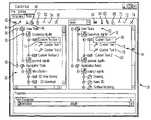
- a GUImay be provided to create custom tools and toolboxes and tasks.
- FIG. 2illustrates an exemplary GUI. The GUI illustrated includes two dialog boxes, 32 , 34 . Dialog box 32 is used to create and organize tools. The standard tools provided with the software program may be shown separate from customized tools created by the user. In the example shown, a directory 36 having a tree structure lists the available tools. Only a selection or a portion of all available tools may be shown in the dialog box 32 . The directory 36 includes two main headings, one for the customized tools 38 and another for the standard tools 40 .
- Icons 42 - 56 on tab 58are respectively used to add, cut, copy, paste, move up, move down, and delete toolboxes and tools. Tools can be moved between toolboxes by dragging and dropping the corresponding tool icon to the desired toolbox in a known manner. Icons 52 and 54 are used to move a tool up or down within a order of the tools within a toolbox.
- the add tool icon 42can be used to create new tools, such macros, etc.
- Dialog box 34is used to create and edit tasks.
- the tasksare shown in a directory 60 having a tree structure.
- Icons 62 - 74are respectively used to add, cut, copy, paste, move up or down, and delete tasks.
- Tasksmay also be added by clicking or dragging a tool or toolbox from the dialog box 32 into an open library file in the dialog box 34 .
- Toolsmay be added to tasks by clicking and dragging the tools from the dialog box 32 into a task listed in dialog box 34 .
- the icons 64 - 72may be used to operate on the task.
- the customize .DGNLIB file 70is selected.
- File 70is a library.
- Custom Task 1 within the customized .DGNLIB libraryis selected.
- the new task icon 62is clicked.
- a new taskappears in the directory with the name “new task”.
- a name for the taskmay then be keyed in by the user.
- Custom Task 1includes Custom Tool 1 and Custom Tool 2 .
- Custom Tool 1 and Custom Tool 2may be added to Task 1 by clicking toolbox 74 in dialog box 32 and dragging the toolbox into Custom Task 1 in dialog box 34 .
- Icons 76 , 78 for Custom Tool 1 and Custom Tool 2are then added to Task 1 .
- the tools within a taskcan be arranged in any order desired by the user. Typically, the user arranges the task in a suggested order of use for performing the task. For example, tool one may be used to perform the first step of the task, tool two the next step etc.
- Icons 70 and 72may be used to reorder the tools within a task. This may be done by selecting the icon for a tool and then clicking the corresponding move up or move down icon.
- the toolsare listed in the desired order. The tools may be used in an order different from the order presented in the user interface.
- Tasksshould not contain the copies of the tools but only references to the tools and toolboxes.
- the taskstores a path, for example, the name of the toolbox and tool, within the task. Therefore, the tasks can contain overlapping sets of tools.
- one custom drawing tool and two tasks, task one and task twocan be created. Each task may refer to the same custom drawing tool.
- task oneis being worked on, task one is selected and the custom drawing tool appears automatically in the user interface, along with the other tools that are needed for task one.
- task twois being worked on, task two is selected from the user interface and the custom drawing tool appears automatically along with a different set of tools that are needed for task two. If the custom drawing tool needs to be modified, it may be modified only once.
- Each task that references the custom toolthen has the updated custom tool.
- a series of tasksmay be created to define a workflow.
- task 80may be first task in the workflow followed by task 82 , etc.
- the order of the tasksmay be changed by selecting the desired task and the corresponding icon 70 , 72 to move up or move down the task within the workflow.
- a usermay be designing a house. The user may have discovered the creation a house design flows best by first designing the foundation, followed, in order, by the framing, walls and roof. The user can create tasks for each of designing the foundation, framing, walls, and roof and then order the tasks to create an efficient work flow.
- the libraryis then associated with a project, or design file(s).
- the librarystores the user interface definition including the tasks and associated tools.
- Once a library is createdit needs to be made available to users.
- the libraryshould be stored at a central location that is accessible to all users who need access.
- the resource librarymay be stored in database that communicates with servers.
- Many libraries containing numerous UID filesmay be created and stored on database. Only some of these resource libraries and UID files may be applicable to a particular project, design file, or model. Therefore, a mechanism for making the relevant UID files available to a user should be provided. In an exemplary embodiment, this is accomplished by attaching a resource library to a design file.
- the resource librariescan be processed at run time to account for any changes to the resource library and distributed to users through a graphical user interface (GUI).
- GUIgraphical user interface
- a resource filehas a type and a name that is used to distribute it to the correct locations in the software program's GUI.
- resource librariesmay be defined with an *.dgnlib extension.
- Tasksmay appear in a task list 90 , as shown FIG. 3 .
- the task listmay be displayed when a task icon 92 is clicked.
- the task listshould include all tasks specified in the libraries specified by the project, design file, etc.
- Task list 92includes the tasks construct chess board 94 , place chess pieces 96 , and annotate chess diagram 98 , with the task 94 selected.
- a task from the task list 90When a task from the task list 90 is selected it becomes the active task.
- the active task's toolsappear in a task navigation tool bar.
- the icons 100 - 103are presented. Icons 100 - 103 represent the tools for drawing a chess diagram.
- an icon 100 - 103is selected, the corresponding tool is retrieved and presented to the user.
- a standard CAD toolcan be used to create and edit UID files. No special tool is required for either the administrator or the regular user.
- feedback information provided to the userFor example, information regarding the file may be displayed on the user interface when a cursor is positioned on the display. Different information may be useful depending on the task being performed. Information provided to the user may be varied based on the active task. For example, assume a visualization task is the active task. As the cursor is moved over a surface of the design, feedback information regarding the material characteristics, amount of light hitting the surface, etc. may be provided to the user. If a modeling task is the active task, the feedback information may include level, color, line style, line weight, surface area, etc. Different information may be provided depending of the specific implementation.
Landscapes
- Engineering & Computer Science (AREA)
- Physics & Mathematics (AREA)
- Theoretical Computer Science (AREA)
- Computer Hardware Design (AREA)
- Evolutionary Computation (AREA)
- Geometry (AREA)
- General Engineering & Computer Science (AREA)
- General Physics & Mathematics (AREA)
- Information Retrieval, Db Structures And Fs Structures Therefor (AREA)
- User Interface Of Digital Computer (AREA)
- Stored Programmes (AREA)
Abstract
Description
Claims (5)
Priority Applications (1)
| Application Number | Priority Date | Filing Date | Title |
|---|---|---|---|
| US11/429,431US7571392B2 (en) | 2002-10-21 | 2006-05-08 | User definable task based interface |
Applications Claiming Priority (2)
| Application Number | Priority Date | Filing Date | Title |
|---|---|---|---|
| US10/274,117US7418666B2 (en) | 2002-10-21 | 2002-10-21 | System, method and computer program product for managing CAD data |
| US11/429,431US7571392B2 (en) | 2002-10-21 | 2006-05-08 | User definable task based interface |
Related Parent Applications (1)
| Application Number | Title | Priority Date | Filing Date |
|---|---|---|---|
| US10/274,117ContinuationUS7418666B2 (en) | 2002-10-21 | 2002-10-21 | System, method and computer program product for managing CAD data |
Publications (2)
| Publication Number | Publication Date |
|---|---|
| US20060271863A1 US20060271863A1 (en) | 2006-11-30 |
| US7571392B2true US7571392B2 (en) | 2009-08-04 |
Family
ID=32092965
Family Applications (2)
| Application Number | Title | Priority Date | Filing Date |
|---|---|---|---|
| US10/274,117Expired - LifetimeUS7418666B2 (en) | 2002-10-21 | 2002-10-21 | System, method and computer program product for managing CAD data |
| US11/429,431Expired - LifetimeUS7571392B2 (en) | 2002-10-21 | 2006-05-08 | User definable task based interface |
Family Applications Before (1)
| Application Number | Title | Priority Date | Filing Date |
|---|---|---|---|
| US10/274,117Expired - LifetimeUS7418666B2 (en) | 2002-10-21 | 2002-10-21 | System, method and computer program product for managing CAD data |
Country Status (1)
| Country | Link |
|---|---|
| US (2) | US7418666B2 (en) |
Cited By (11)
| Publication number | Priority date | Publication date | Assignee | Title |
|---|---|---|---|---|
| US20070120576A1 (en)* | 2005-11-28 | 2007-05-31 | Autodesk, Inc. | Look-Up Table Action |
| US20070120714A1 (en)* | 2005-11-28 | 2007-05-31 | John Beltran | Dynamic blocks |
| US20070120870A1 (en)* | 2005-11-28 | 2007-05-31 | Ford John G | Method and system for generating dynamic blocks |
| US20110276908A1 (en)* | 2010-05-06 | 2011-11-10 | Cadence Design Systems, Inc. | System and method for management of controls in a graphical user interface |
| US20120066642A1 (en)* | 2009-06-15 | 2012-03-15 | Zte Corporation | Method and system for realizing dynamic adjustment of toolbar button display |
| US20120232875A1 (en)* | 2011-03-08 | 2012-09-13 | Honeywell International Inc. | System and method for simulating operation of substructures of a chemical processing plant |
| US20130073994A1 (en)* | 2011-09-19 | 2013-03-21 | Microsoft Corporation | Web-based workflow service visualization and navigation |
| US9454623B1 (en) | 2010-12-16 | 2016-09-27 | Bentley Systems, Incorporated | Social computer-aided engineering design projects |
| US10338959B2 (en) | 2015-07-13 | 2019-07-02 | Microsoft Technology Licensing, Llc | Task state tracking in systems and services |
| US10635281B2 (en) | 2016-02-12 | 2020-04-28 | Microsoft Technology Licensing, Llc | Natural language task completion platform authoring for third party experiences |
| US10754495B1 (en) | 2016-04-05 | 2020-08-25 | Bentley Systems, Incorporated | 3-D screen menus |
Families Citing this family (31)
| Publication number | Priority date | Publication date | Assignee | Title |
|---|---|---|---|---|
| US7280123B2 (en)* | 2004-01-13 | 2007-10-09 | Bentley Systems, Inc. | Display priority for 2D CAD documents |
| JP4676784B2 (en)* | 2004-03-02 | 2011-04-27 | 株式会社リコー | Process management apparatus, process management method, and process management program |
| US9324239B2 (en)* | 2004-03-19 | 2016-04-26 | Sap Se | Authoring tool to structure and create a computer-based training course, and having role-specific functions |
| WO2006034218A2 (en)* | 2004-09-20 | 2006-03-30 | On A Chart, Llc | Electronic file system graphical user interface |
| US20060101076A1 (en)* | 2004-11-10 | 2006-05-11 | Parag Patel | Electronic file system graphic user interface including user defined relationship symbology between folders |
| US20060075326A1 (en)* | 2004-09-20 | 2006-04-06 | Parag Patel | Research software tool with flowchart graphic user interface |
| EP1672533B1 (en)* | 2004-12-20 | 2013-02-27 | Dassault Systèmes | Method and computer system for interacting with a database |
| EP1675045A1 (en)* | 2004-12-21 | 2006-06-28 | Siemens Aktiengesellschaft | Exchange of description data between projects using inter-project-interfaces |
| US20070198588A1 (en)* | 2005-10-17 | 2007-08-23 | Siemens Corporate Research Inc | Automatic Qualification of Plant Equipment |
| US7644363B2 (en)* | 2006-04-10 | 2010-01-05 | Autodesk, Inc. | “For-each” label components in CAD drawings |
| US20080189627A1 (en)* | 2007-02-07 | 2008-08-07 | Microsoft Corporation | Execution of application based on task selection |
| JP2009218711A (en)* | 2008-03-07 | 2009-09-24 | Canon Inc | Information processor, image processor, control method of information processor, control method of image processor and program |
| US20090328028A1 (en)* | 2008-06-25 | 2009-12-31 | O'rourke Connor | Electronic documents and methods for updating resource files for an application |
| US20100241477A1 (en)* | 2009-03-19 | 2010-09-23 | Scenario Design, Llc | Dimensioned modeling system |
| US20100241471A1 (en)* | 2009-03-19 | 2010-09-23 | Scenario Design, Llc | Integration system supporting dimensioned modeling system |
| US20110016421A1 (en)* | 2009-07-20 | 2011-01-20 | Microsoft Corporation | Task oriented user interface platform |
| JP2011124957A (en)* | 2009-12-14 | 2011-06-23 | Canon Inc | Information processor, method to control the same, program, and memory medium |
| US8290900B2 (en)* | 2010-04-24 | 2012-10-16 | Research In Motion Limited | Apparatus, and associated method, for synchronizing directory services |
| KR101833581B1 (en)* | 2011-03-17 | 2018-02-28 | 아디타즈, 인크. | System and method for realizing a building system |
| US20120331407A1 (en)* | 2011-06-21 | 2012-12-27 | Google Inc. | Temporal Task-Based Tab Management |
| WO2013013216A1 (en)* | 2011-07-20 | 2013-01-24 | Fauklner Adrienne | System and method for designing accessible and usable spaces having built-in furnishings in a multi-unit environment |
| US20130339078A1 (en) | 2012-06-18 | 2013-12-19 | Coaxis, Inc. | System and method linking building information modeling and enterprise resource planning |
| US9971592B2 (en)* | 2013-02-27 | 2018-05-15 | Adobe Systems Incorporated | Method and apparatus for a workflow-based software purchase |
| WO2014142990A1 (en)* | 2013-03-15 | 2014-09-18 | Brigham Young University | Scalable multi-user cad system and apparatus |
| DE102014104060B4 (en) | 2014-03-25 | 2024-09-12 | Dr. Ing. H.C. F. Porsche Aktiengesellschaft | Procedure for processing a file |
| US20150324068A1 (en)* | 2014-05-08 | 2015-11-12 | Rolta India Ltd | User interface structure (uis) for geographic information system applications |
| US9946894B2 (en)* | 2014-06-27 | 2018-04-17 | Panasonic Intellectual Property Management Co., Ltd. | Data processing method and data processing device |
| US10061872B1 (en) | 2016-09-01 | 2018-08-28 | Bentley Systems, Incorporated | Techniques for suppressing unwanted clashes |
| US10796266B2 (en)* | 2018-05-08 | 2020-10-06 | The Boeing Company | Automated context driven build plan lifecycle |
| CN110826185B (en)* | 2019-10-11 | 2023-10-24 | 西安工程大学 | Method for establishing secondary development bearing part library based on CAD |
| CN113626908A (en)* | 2021-07-14 | 2021-11-09 | 机械工业第九设计研究院有限公司 | Planning and designing method for automobile factory coating process |
Citations (33)
| Publication number | Priority date | Publication date | Assignee | Title |
|---|---|---|---|---|
| US5361871A (en)* | 1991-08-20 | 1994-11-08 | Digicomp Research Corporation | Product information system for shoppers |
| US5467444A (en)* | 1990-11-07 | 1995-11-14 | Hitachi, Ltd. | Method of three-dimensional display of object-oriented figure information and system thereof |
| WO1998000768A2 (en) | 1996-06-21 | 1998-01-08 | Paul, Hastings, Janofsky & Walker | Task-based classification and analysis system |
| WO2001039409A1 (en) | 1999-11-29 | 2001-05-31 | Acterna, Llc | A task oriented graphical user interface for a communication test set |
| US20010035882A1 (en) | 2000-04-06 | 2001-11-01 | Microsoft Corporation | Method and system for clustering and grouping taskbar buttons |
| US6366782B1 (en) | 1999-10-08 | 2002-04-02 | Motorola, Inc. | Method and apparatus for allowing a user of a display-based terminal to communicate with communication units in a communication system |
| US20030012344A1 (en) | 2001-07-10 | 2003-01-16 | Rita Agarwal | System and a method for emergency services |
| US6538623B1 (en) | 1999-05-13 | 2003-03-25 | Pirooz Parnian | Multi-media data collection tool kit having an electronic multi-media “case” file and method of use |
| US20040085363A1 (en) | 2002-11-06 | 2004-05-06 | Lawrence Casey J. | System and method for enabling access to a data source through a graphical interface |
| US20040103431A1 (en) | 2001-06-21 | 2004-05-27 | Crisis Technologies, Inc. | Method and system for emergency planning and management of a facility |
| US20040119752A1 (en) | 2002-12-23 | 2004-06-24 | Joerg Beringer | Guided procedure framework |
| WO2004055641A2 (en) | 2002-12-13 | 2004-07-01 | Business Performance Group, Llc | Collaboration framework |
| JP2004220390A (en) | 2003-01-16 | 2004-08-05 | Hitachi Ltd | Method and apparatus for automatically generating screen control definition |
| US20040210386A1 (en) | 2002-07-03 | 2004-10-21 | Terragraphix, Inc. | System for communicating and associating information with a geographic location |
| US6857105B1 (en) | 2002-02-19 | 2005-02-15 | Adobe Systems Incorporated | Method and apparatus for expanding and contracting graphical function displays |
| US20050055330A1 (en) | 2001-05-15 | 2005-03-10 | Britton Colin P. | Surveillance, monitoring and real-time events platform |
| US6868340B2 (en) | 2001-03-30 | 2005-03-15 | John Franklin Alexander | Emergency management system |
| US6895373B2 (en)* | 1999-04-09 | 2005-05-17 | Public Service Company Of New Mexico | Utility station automated design system and method |
| US20050138631A1 (en) | 2003-12-17 | 2005-06-23 | Victoria Bellotti | System and method for providing metadata interaction and visualization with task-related objects |
| US20050138559A1 (en) | 2003-12-19 | 2005-06-23 | International Business Machines Corporation | Method, system and computer program for providing interactive assistance in a computer application program |
| US20050160371A1 (en) | 1999-08-23 | 2005-07-21 | Sentillion, Inc. | Application launchpad |
| US6925609B1 (en) | 2000-01-31 | 2005-08-02 | International Business Machines Corporation | Hybrid task and file oriented user interface |
| US6959421B1 (en) | 2001-11-09 | 2005-10-25 | Cypress Semiconductor Corporation | Quick click icons for workspace flow between views for major subsystems and views within a design tool |
| US6966033B1 (en) | 2001-09-28 | 2005-11-15 | Emc Corporation | Methods and apparatus for graphically managing resources |
| US6970791B1 (en) | 2003-05-23 | 2005-11-29 | Verachem, Llc | Tailored user interfaces for molecular modeling |
| US20050278655A1 (en) | 2004-06-14 | 2005-12-15 | Sims Lisa K | Multiple application viewing |
| US20050289479A1 (en) | 2004-06-23 | 2005-12-29 | Broadcom Corporation | Method and system for providing text information in an application framework for a wireless device |
| US20060005132A1 (en) | 2004-06-30 | 2006-01-05 | Microsoft Corporation | Smart UI recording and playback framework |
| US20060010422A1 (en) | 2000-03-16 | 2006-01-12 | Silicon Graphics, Inc. | Common user interface development toolkit for a system administration program |
| US20060026519A1 (en) | 2004-07-01 | 2006-02-02 | Alexander Vaindiner | Providing programmatic access to an application's user interface elements |
| US20060031849A1 (en) | 2004-04-06 | 2006-02-09 | International Business Machines Corporation | User task interface in a Web application |
| US20060036964A1 (en) | 2004-08-16 | 2006-02-16 | Microsoft Corporation | User interface for displaying selectable software functionality controls that are relevant to a selected object |
| US20060053376A1 (en) | 2002-10-04 | 2006-03-09 | Joanna Ng | Method and apparatus for managing a collection of portlets in a portal server |
Family Cites Families (15)
| Publication number | Priority date | Publication date | Assignee | Title |
|---|---|---|---|---|
| US5019961A (en)* | 1989-04-05 | 1991-05-28 | Cadware, Inc. | Computer apparatus and method for logical modelling |
| US5293479A (en)* | 1991-07-08 | 1994-03-08 | Quintero Smith Incorporated | Design tool and method for preparing parametric assemblies |
| US5634016A (en)* | 1993-01-21 | 1997-05-27 | Blade Software, Inc. | Event management system |
| US5838965A (en)* | 1994-11-10 | 1998-11-17 | Cadis, Inc. | Object oriented database management system |
| US5950201A (en)* | 1996-12-06 | 1999-09-07 | International Business Machines Corporation | Computerized design automation method using a single logical PFVL paradigm |
| JP3959150B2 (en)* | 1997-04-02 | 2007-08-15 | 株式会社沖データ | Heater control method for facsimile machine |
| US6850946B1 (en)* | 1999-05-26 | 2005-02-01 | Wireless Valley Communications, Inc. | Method and system for a building database manipulator |
| WO2002025596A2 (en)* | 2000-09-19 | 2002-03-28 | Draftlogic System Inc, | System for client-driven automated computer-aided drafting |
| WO2002037394A2 (en)* | 2000-10-30 | 2002-05-10 | Tririga, Inc. | sUSINESS ASSET MANAGEMENT SYSTEM |
| US20020129001A1 (en)* | 2000-12-12 | 2002-09-12 | Levkoff Jonathan S. | Method and system for assimilation, integration and deployment of architectural, engineering and construction information technology |
| US6823342B2 (en)* | 2001-05-15 | 2004-11-23 | Vykor, Inc. | Method and system for capturing, managing, and disseminating manufacturing knowledge |
| US6868297B1 (en)* | 2001-09-17 | 2005-03-15 | Impactxoft | Method and system for designing objects using functional modeling |
| WO2003077124A1 (en)* | 2002-03-07 | 2003-09-18 | Honeywell Inc. | Interaction design system |
| AU2003223746A1 (en)* | 2002-04-25 | 2003-11-10 | Arc International | Apparatus and method for managing integrated circuit designs |
| US20040024624A1 (en)* | 2002-07-31 | 2004-02-05 | Ciscon Lawrence A. | Method and system for leveraging functional knowledge using a requirement and space planning tool in an engineering project |
- 2002
- 2002-10-21USUS10/274,117patent/US7418666B2/ennot_activeExpired - Lifetime
- 2006
- 2006-05-08USUS11/429,431patent/US7571392B2/ennot_activeExpired - Lifetime
Patent Citations (34)
| Publication number | Priority date | Publication date | Assignee | Title |
|---|---|---|---|---|
| US5467444A (en)* | 1990-11-07 | 1995-11-14 | Hitachi, Ltd. | Method of three-dimensional display of object-oriented figure information and system thereof |
| US5361871A (en)* | 1991-08-20 | 1994-11-08 | Digicomp Research Corporation | Product information system for shoppers |
| WO1998000768A2 (en) | 1996-06-21 | 1998-01-08 | Paul, Hastings, Janofsky & Walker | Task-based classification and analysis system |
| US6289317B1 (en) | 1996-06-21 | 2001-09-11 | Paul Hastings, Janofsky & Walker | Task-based classification and analysis system |
| US6895373B2 (en)* | 1999-04-09 | 2005-05-17 | Public Service Company Of New Mexico | Utility station automated design system and method |
| US6538623B1 (en) | 1999-05-13 | 2003-03-25 | Pirooz Parnian | Multi-media data collection tool kit having an electronic multi-media “case” file and method of use |
| US20050160371A1 (en) | 1999-08-23 | 2005-07-21 | Sentillion, Inc. | Application launchpad |
| US6366782B1 (en) | 1999-10-08 | 2002-04-02 | Motorola, Inc. | Method and apparatus for allowing a user of a display-based terminal to communicate with communication units in a communication system |
| WO2001039409A1 (en) | 1999-11-29 | 2001-05-31 | Acterna, Llc | A task oriented graphical user interface for a communication test set |
| US6925609B1 (en) | 2000-01-31 | 2005-08-02 | International Business Machines Corporation | Hybrid task and file oriented user interface |
| US20060010422A1 (en) | 2000-03-16 | 2006-01-12 | Silicon Graphics, Inc. | Common user interface development toolkit for a system administration program |
| US20010035882A1 (en) | 2000-04-06 | 2001-11-01 | Microsoft Corporation | Method and system for clustering and grouping taskbar buttons |
| US6868340B2 (en) | 2001-03-30 | 2005-03-15 | John Franklin Alexander | Emergency management system |
| US20050055330A1 (en) | 2001-05-15 | 2005-03-10 | Britton Colin P. | Surveillance, monitoring and real-time events platform |
| US20040103431A1 (en) | 2001-06-21 | 2004-05-27 | Crisis Technologies, Inc. | Method and system for emergency planning and management of a facility |
| US20030012344A1 (en) | 2001-07-10 | 2003-01-16 | Rita Agarwal | System and a method for emergency services |
| US6966033B1 (en) | 2001-09-28 | 2005-11-15 | Emc Corporation | Methods and apparatus for graphically managing resources |
| US6959421B1 (en) | 2001-11-09 | 2005-10-25 | Cypress Semiconductor Corporation | Quick click icons for workspace flow between views for major subsystems and views within a design tool |
| US6857105B1 (en) | 2002-02-19 | 2005-02-15 | Adobe Systems Incorporated | Method and apparatus for expanding and contracting graphical function displays |
| US20040210386A1 (en) | 2002-07-03 | 2004-10-21 | Terragraphix, Inc. | System for communicating and associating information with a geographic location |
| US20060053376A1 (en) | 2002-10-04 | 2006-03-09 | Joanna Ng | Method and apparatus for managing a collection of portlets in a portal server |
| US20040085363A1 (en) | 2002-11-06 | 2004-05-06 | Lawrence Casey J. | System and method for enabling access to a data source through a graphical interface |
| WO2004055641A2 (en) | 2002-12-13 | 2004-07-01 | Business Performance Group, Llc | Collaboration framework |
| US20040119752A1 (en) | 2002-12-23 | 2004-06-24 | Joerg Beringer | Guided procedure framework |
| JP2004220390A (en) | 2003-01-16 | 2004-08-05 | Hitachi Ltd | Method and apparatus for automatically generating screen control definition |
| US6970791B1 (en) | 2003-05-23 | 2005-11-29 | Verachem, Llc | Tailored user interfaces for molecular modeling |
| US20050138631A1 (en) | 2003-12-17 | 2005-06-23 | Victoria Bellotti | System and method for providing metadata interaction and visualization with task-related objects |
| US20050138559A1 (en) | 2003-12-19 | 2005-06-23 | International Business Machines Corporation | Method, system and computer program for providing interactive assistance in a computer application program |
| US20060031849A1 (en) | 2004-04-06 | 2006-02-09 | International Business Machines Corporation | User task interface in a Web application |
| US20050278655A1 (en) | 2004-06-14 | 2005-12-15 | Sims Lisa K | Multiple application viewing |
| US20050289479A1 (en) | 2004-06-23 | 2005-12-29 | Broadcom Corporation | Method and system for providing text information in an application framework for a wireless device |
| US20060005132A1 (en) | 2004-06-30 | 2006-01-05 | Microsoft Corporation | Smart UI recording and playback framework |
| US20060026519A1 (en) | 2004-07-01 | 2006-02-02 | Alexander Vaindiner | Providing programmatic access to an application's user interface elements |
| US20060036964A1 (en) | 2004-08-16 | 2006-02-16 | Microsoft Corporation | User interface for displaying selectable software functionality controls that are relevant to a selected object |
Cited By (17)
| Publication number | Priority date | Publication date | Assignee | Title |
|---|---|---|---|---|
| US20070120714A1 (en)* | 2005-11-28 | 2007-05-31 | John Beltran | Dynamic blocks |
| US20070120870A1 (en)* | 2005-11-28 | 2007-05-31 | Ford John G | Method and system for generating dynamic blocks |
| US7860691B2 (en) | 2005-11-28 | 2010-12-28 | Autodesk, Inc. | Dynamic blocks |
| US7978206B2 (en)* | 2005-11-28 | 2011-07-12 | Autodesk, Inc. | Look-up table action |
| US7999827B2 (en) | 2005-11-28 | 2011-08-16 | Autodesk, Inc. | Method and system for generating dynamic blocks |
| US20070120576A1 (en)* | 2005-11-28 | 2007-05-31 | Autodesk, Inc. | Look-Up Table Action |
| US20120066642A1 (en)* | 2009-06-15 | 2012-03-15 | Zte Corporation | Method and system for realizing dynamic adjustment of toolbar button display |
| US8689121B2 (en)* | 2010-05-06 | 2014-04-01 | Cadence Design Systems, Inc. | System and method for management of controls in a graphical user interface |
| US20110276908A1 (en)* | 2010-05-06 | 2011-11-10 | Cadence Design Systems, Inc. | System and method for management of controls in a graphical user interface |
| US9454623B1 (en) | 2010-12-16 | 2016-09-27 | Bentley Systems, Incorporated | Social computer-aided engineering design projects |
| US20120232875A1 (en)* | 2011-03-08 | 2012-09-13 | Honeywell International Inc. | System and method for simulating operation of substructures of a chemical processing plant |
| US9002686B2 (en)* | 2011-03-08 | 2015-04-07 | Honeywell International Inc. | System and method for simulating operation of substructures of a chemical processing plant |
| US8862975B2 (en)* | 2011-09-19 | 2014-10-14 | Microsoft Corporation | Web-based workflow service visualization and navigation |
| US20130073994A1 (en)* | 2011-09-19 | 2013-03-21 | Microsoft Corporation | Web-based workflow service visualization and navigation |
| US10338959B2 (en) | 2015-07-13 | 2019-07-02 | Microsoft Technology Licensing, Llc | Task state tracking in systems and services |
| US10635281B2 (en) | 2016-02-12 | 2020-04-28 | Microsoft Technology Licensing, Llc | Natural language task completion platform authoring for third party experiences |
| US10754495B1 (en) | 2016-04-05 | 2020-08-25 | Bentley Systems, Incorporated | 3-D screen menus |
Also Published As
| Publication number | Publication date |
|---|---|
| US20040075688A1 (en) | 2004-04-22 |
| US7418666B2 (en) | 2008-08-26 |
| US20060271863A1 (en) | 2006-11-30 |
Similar Documents
| Publication | Publication Date | Title |
|---|---|---|
| US7571392B2 (en) | User definable task based interface | |
| EP1922604B1 (en) | Command user interface for displaying selectable functionality controls in a database application | |
| US7610258B2 (en) | System and method for exposing a child list | |
| US6182095B1 (en) | Document generator | |
| US6418428B1 (en) | Object oriented data access and analysis system | |
| US7581189B2 (en) | Dynamically generating a database report during a report building process | |
| US20110098985A1 (en) | System and method for managing information | |
| US9547409B2 (en) | Navigable graph of a service level management document | |
| US8578262B2 (en) | Cad-interfaced, automated system for assisting the architectural process | |
| JP2009064469A (en) | Method of providing access to object parameter within simulation model | |
| US20090094271A1 (en) | Variable driven method and system for the management and display of information | |
| US20020054155A1 (en) | Data module design system | |
| US6898474B2 (en) | Method and system for creating and managing engineered time standards | |
| US20030151632A1 (en) | User interface system for applying decision values to objects | |
| US20050246212A1 (en) | Process navigator | |
| WO2008145981A2 (en) | Information management systems | |
| KR20030009643A (en) | Project EDMS(electronic document management system) | |
| JP2004118354A (en) | Document management system and document management program | |
| JP2002288186A (en) | Method and system for classification and management of electronic data | |
| EP1577751B1 (en) | Method, computer program product and data processing system for entering assignments of a first object of a first object hierarchy to objects of a second object hierarchy | |
| Munro | Forming Relationships | |
| KR101802284B1 (en) | Method and system hiding the storage location for file in computer | |
| AU2014204514A1 (en) | System and method for managing information | |
| Series | Model Navigation | |
| Vesterli | Drag-and-Drop Building |
Legal Events
| Date | Code | Title | Description |
|---|---|---|---|
| AS | Assignment | Owner name:BENTLEY SYSTEMS, INC., PENNSYLVANIA Free format text:ASSIGNMENT OF ASSIGNORS INTEREST;ASSIGNOR:CORTESI, GINO;REEL/FRAME:018155/0761 Effective date:20060726 | |
| STCF | Information on status: patent grant | Free format text:PATENTED CASE | |
| FEPP | Fee payment procedure | Free format text:PAYOR NUMBER ASSIGNED (ORIGINAL EVENT CODE: ASPN); ENTITY STATUS OF PATENT OWNER: LARGE ENTITY | |
| CC | Certificate of correction | ||
| AS | Assignment | Owner name:JPMORGAN CHASE BANK, N.A., AS ADMINISTRATIVE AGENT Free format text:SECURITY AGREEMENT;ASSIGNOR:BENTLEY SYSTEMS INCORPORATED;REEL/FRAME:025902/0806 Effective date:20110211 | |
| AS | Assignment | Owner name:BENTLEY SYSTEMS, INCORPORATED, PENNSYLVANIA Free format text:RELEASE OF SECURITY INTERESTS;ASSIGNOR:JPMORGAN CHASE BANK, N.A.;REEL/FRAME:027682/0012 Effective date:20120202 | |
| AS | Assignment | Owner name:PNC BANK, NATIONAL ASSOCIATION, PENNSYLVANIA Free format text:SECURITY AGREEMENT;ASSIGNOR:BENTLEY SYSTEMS, INCORPORATED;REEL/FRAME:027794/0026 Effective date:20120202 | |
| FPAY | Fee payment | Year of fee payment:4 | |
| FPAY | Fee payment | Year of fee payment:8 | |
| MAFP | Maintenance fee payment | Free format text:PAYMENT OF MAINTENANCE FEE, 12TH YEAR, LARGE ENTITY (ORIGINAL EVENT CODE: M1553); ENTITY STATUS OF PATENT OWNER: LARGE ENTITY Year of fee payment:12 |