US7570994B2 - Apparatus and method for maintaining a defibrillator battery charge and optionally communicating - Google Patents
Apparatus and method for maintaining a defibrillator battery charge and optionally communicatingDownload PDFInfo
- Publication number
- US7570994B2 US7570994B2US10/423,805US42380503AUS7570994B2US 7570994 B2US7570994 B2US 7570994B2US 42380503 AUS42380503 AUS 42380503AUS 7570994 B2US7570994 B2US 7570994B2
- Authority
- US
- United States
- Prior art keywords
- defibrillator
- aed
- docking station
- housing
- energy
- Prior art date
- Legal status (The legal status is an assumption and is not a legal conclusion. Google has not performed a legal analysis and makes no representation as to the accuracy of the status listed.)
- Expired - Lifetime, expires
Links
Images


Classifications
- A—HUMAN NECESSITIES
- A61—MEDICAL OR VETERINARY SCIENCE; HYGIENE
- A61N—ELECTROTHERAPY; MAGNETOTHERAPY; RADIATION THERAPY; ULTRASOUND THERAPY
- A61N1/00—Electrotherapy; Circuits therefor
- A61N1/18—Applying electric currents by contact electrodes
- A61N1/32—Applying electric currents by contact electrodes alternating or intermittent currents
- A61N1/38—Applying electric currents by contact electrodes alternating or intermittent currents for producing shock effects
- A61N1/39—Heart defibrillators
- A61N1/3975—Power supply
- H—ELECTRICITY
- H02—GENERATION; CONVERSION OR DISTRIBUTION OF ELECTRIC POWER
- H02J—CIRCUIT ARRANGEMENTS OR SYSTEMS FOR SUPPLYING OR DISTRIBUTING ELECTRIC POWER; SYSTEMS FOR STORING ELECTRIC ENERGY
- H02J50/00—Circuit arrangements or systems for wireless supply or distribution of electric power
- H02J50/05—Circuit arrangements or systems for wireless supply or distribution of electric power using capacitive coupling
- H—ELECTRICITY
- H02—GENERATION; CONVERSION OR DISTRIBUTION OF ELECTRIC POWER
- H02J—CIRCUIT ARRANGEMENTS OR SYSTEMS FOR SUPPLYING OR DISTRIBUTING ELECTRIC POWER; SYSTEMS FOR STORING ELECTRIC ENERGY
- H02J7/00—Circuit arrangements for charging or depolarising batteries or for supplying loads from batteries
- H02J7/00032—Circuit arrangements for charging or depolarising batteries or for supplying loads from batteries characterised by data exchange
- H02J7/00034—Charger exchanging data with an electronic device, i.e. telephone, whose internal battery is under charge
- H—ELECTRICITY
- H02—GENERATION; CONVERSION OR DISTRIBUTION OF ELECTRIC POWER
- H02J—CIRCUIT ARRANGEMENTS OR SYSTEMS FOR SUPPLYING OR DISTRIBUTING ELECTRIC POWER; SYSTEMS FOR STORING ELECTRIC ENERGY
- H02J7/00—Circuit arrangements for charging or depolarising batteries or for supplying loads from batteries
- H02J7/0042—Circuit arrangements for charging or depolarising batteries or for supplying loads from batteries characterised by the mechanical construction
- H02J7/0044—Circuit arrangements for charging or depolarising batteries or for supplying loads from batteries characterised by the mechanical construction specially adapted for holding portable devices containing batteries
- A—HUMAN NECESSITIES
- A61—MEDICAL OR VETERINARY SCIENCE; HYGIENE
- A61N—ELECTROTHERAPY; MAGNETOTHERAPY; RADIATION THERAPY; ULTRASOUND THERAPY
- A61N1/00—Electrotherapy; Circuits therefor
- A61N1/18—Applying electric currents by contact electrodes
- A61N1/32—Applying electric currents by contact electrodes alternating or intermittent currents
- A61N1/36—Applying electric currents by contact electrodes alternating or intermittent currents for stimulation
- A61N1/372—Arrangements in connection with the implantation of stimulators
- A61N1/378—Electrical supply
- A61N1/3787—Electrical supply from an external energy source
- H—ELECTRICITY
- H02—GENERATION; CONVERSION OR DISTRIBUTION OF ELECTRIC POWER
- H02J—CIRCUIT ARRANGEMENTS OR SYSTEMS FOR SUPPLYING OR DISTRIBUTING ELECTRIC POWER; SYSTEMS FOR STORING ELECTRIC ENERGY
- H02J2310/00—The network for supplying or distributing electric power characterised by its spatial reach or by the load
- H02J2310/10—The network having a local or delimited stationary reach
- H02J2310/20—The network being internal to a load
- H02J2310/23—The load being a medical device, a medical implant, or a life supporting device
- H—ELECTRICITY
- H02—GENERATION; CONVERSION OR DISTRIBUTION OF ELECTRIC POWER
- H02J—CIRCUIT ARRANGEMENTS OR SYSTEMS FOR SUPPLYING OR DISTRIBUTING ELECTRIC POWER; SYSTEMS FOR STORING ELECTRIC ENERGY
- H02J50/00—Circuit arrangements or systems for wireless supply or distribution of electric power
- H02J50/10—Circuit arrangements or systems for wireless supply or distribution of electric power using inductive coupling
- H—ELECTRICITY
- H02—GENERATION; CONVERSION OR DISTRIBUTION OF ELECTRIC POWER
- H02J—CIRCUIT ARRANGEMENTS OR SYSTEMS FOR SUPPLYING OR DISTRIBUTING ELECTRIC POWER; SYSTEMS FOR STORING ELECTRIC ENERGY
- H02J50/00—Circuit arrangements or systems for wireless supply or distribution of electric power
- H02J50/30—Circuit arrangements or systems for wireless supply or distribution of electric power using light, e.g. lasers
Definitions
- the inventionrelates to medical devices, and in particular, to wirelessly charging a battery within a defibrillator.
- Cardiac arrestis a life-threatening medical condition that may be treated with external defibrillation.
- External defibrillationincludes applying electrodes to the patient's chest and delivering an electric shock to the patient to depolarize the patient's heart and restore normal sinus rhythm. The chance that a patient's heart can be successfully defibrillated increases significantly if a defibrillation pulse is applied quickly.
- AEDsautomated external defibrillators
- An AEDmay be used infrequently, whether it is placed in a commercial setting or in a private household.
- the battery within the AEDwill gradually discharge because of self-discharge and automated self-testing that is conducted on a periodic basis (daily, weekly, etc.). Since the AED is used infrequently, the battery status may not be checked on a regular basis. As a result, when the AED is brought into use, possibly years after purchase, the battery may not have sufficient energy to allow the AED to perform its intended function (ECG analysis and defibrillation).
- AEDs deployedmay be periodically checked.
- a personsuch as a security worker, may be assigned to make an inspection of each AED and confirm that the device is operational.
- the inspectionmay be relatively simple, because many AEDs perform one or more automatic self-diagnostic routines and provide one or more status indications that the device is operational or in need of service.
- the responsible personregularly reviews each AED and checks its associated status indicators.
- the responsible personmay also be required to prepare and maintain records showing that the inspections have been performed, as well as log the status and repair history of the AEDs.
- the cost of inspectionmay be significant.
- a deployed AEDmay be unprepared to provide defibrillation therapy if the responsible person fails to make an inspection, forgets to make an inspection, or makes an inspection error.
- AEDsdisposable batteries power most AEDs.
- AEDswhich have an option for using rechargeable batteries. In these AEDs, removing them from the unit and connecting an AC-powered charger charge the batteries.
- a problem associated with using these AEDs using AC poweris that the leakage current to the patient must be kept below the limits set by industry standards, which require the use of large isolation components, typically transformers. These devices, while they have proved effective as AEDs, are also larger and heavier and thus make the AEDs more difficult to use and transport.
- defibrillatorsAnother challenge with defibrillators is providing for user safety from the high voltages generated by the AED.
- safetyis provided by having no exposed, user-accessible contacts other than the defibrillation electrodes (pads).
- these AEDsutilize removable batteries that are inserted into the AED and removed when the battery is depleted. Having a traditional battery charger that is powered by the AC line power typically has user-accessible contacts that would have to be electrically isolated within the AED. This isolation would increase the cost and size of the AED.
- the inventionovercomes the problems of the prior art.
- the inventionprovides medical device systems and methods to wirelessly transfer energy from an external source to a battery within the medical device.
- the inventiontransfers the energy through a non-contact interface through a cradle means or a docking station means.
- the rate of energy transferis generally equal to the energy drain caused by self-discharge and automated self-testing. Accordingly, since the rate of energy transfer is lower than that required to run the medical device continuously, several wireless methods of energy transfer may be used.
- the present inventionprovides wireless energy transfer methods, such as inductively, capacitively, acoustically, optically, and electromagnetically transferring energy from an external source to a medical device.
- the inventionmay optionally provide the capability for the medical device to communicate diagnostic and non-diagnostic data to the external source.
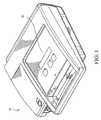
- FIG. 1is a perspective view of a portable defibrillator in accordance with the present invention
- FIG. 2is a perspective drawing of an automated external defibrillator in a cabinet docking station according to an embodiment of the invention.
- FIG. 3is a perspective drawing of an automated external defibrillator in a bracket docking station according to another embodiment of the invention.
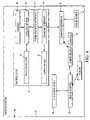
- FIG. 4is a block diagram illustrating a system for wirelessly charging an automated external defibrillator and optionally transmitting data from an automated external defibrillator, according to an embodiment of the invention.
- FIG. 5is a schematic representation illustrating an embodiment for wirelessly charging an automated defibrillator, according to the present invention
- FIG. 6is a schematic representation illustrating another embodiment for wirelessly charging an automated defibrillator, according to the present invention.
- FIG. 7is a flow diagram illustrating a technique for wirelessly charging a medical device such as an AED according to an embodiment of the invention.
- FIG. 8is a flow diagram illustrating a technique for wirelessly charging a medical device such as an AED according to another embodiment of the invention.
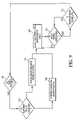
- FIG. 9is a flow diagram illustrating a technique for wirelessly charging and communicating with a medical device such as an AED according to an embodiment of the invention.
- the present inventionis not limited to automatic external defibrillators and may be employed in many various types of electronic and mechanical devices for treating patient medical conditions such as external defibrillators, implantable defibrillators, pacemakers, cardioverter defibrillators, and neurostimulators.
- external defibrillatorsimplantable defibrillators
- pacemakerspacemakers
- cardioverter defibrillatorsand neurostimulators.
- neurostimulatorsfor purposes of illustration only, however, the present invention is below described in the context of automatic external defibrillators.
- AED 10is capable of administering defibrillation therapy to a patient.
- AED 10includes an electrical source (not shown) that can generate one or more shocks to defibrillate the heart of a patient.
- the shocksmay be delivered to the patient via two electrodes (not shown), which may be hand-held electrode paddles or adhesive electrode pads placed externally on the skin of the patient.
- the electrodesmay be packaged in a sealed pouch (not shown), such as an airtight foil bag, which protects the electrodes from the environment.
- the electrodesmay include substances that may degrade or dry out when exposed to air.
- the electrodesmay include a hydrogel layer that hydrates the patient's skin, forms an interface with the patient, promotes adhesion of the electrodes to the skin and reduces the risk of burns.
- the electrodesmay be stored in a pouch to prevent the hydrogel from drying out and losing its desirable properties.
- the pouchmay be stowed inside AED 10 or inside cabinet 12 ( FIG. 2 & FIG. 3 ).
- An operator using AED 10typically opens the pouch, retrieves the electrodes and places the electrodes in the correct positions on the patient's chest. In some models of AED 10 , the operator may also couple the electrodes to AED 10 by plugging an electrical connector into a receptacle on AED 10 .
- Electrodes of the kind described aboveare intended for use on one occasion. Following use, the electrodes are discarded, and AED 10 may be supplied with a fresh pouch. Even if the electrodes are not used, however, the electrodes may have a shelf life. The pouch should be replaced when the shelf life expires.
- AED 10includes an internal power source 62 ( FIG. 4 ).
- Power source 62 for many models of AED 10is a battery. Battery power is advantageous in many respects.
- the patientmay be far from an electrical outlet. In those situations, AED 10 may rely upon a battery to supply the energy for the defibrillation shocks.
- a power supply in the form of a batterymakes AED 10 portable and useful in a wider variety of emergency situations.
- AED 10also comprises an energy storage device (not shown), such as one or more capacitors, and a charging circuit (not shown), such as a flyback charger.
- an energy storage devicesuch as one or more capacitors
- a charging circuitsuch as a flyback charger.
- the charging circuittransfers energy from the power supply to the energy storage device.
- the energy stored in the energy storage devicereaches a desired level, AED 10 is ready to deliver defibrillation therapy.
- the therapymay be delivered automatically or manually.
- AED 10may further include a microprocessor (not shown) that controls various functions of AED 10 .
- the microprocessormay govern charging of the energy storage device, for example, or may evaluate heart rhythms of the patient sensed via the electrodes, or may deliver the defibrillation shocks automatically.
- the microprocessormay further execute a routine that performs a self-diagnostic test of AED 10 and acquire status information as a function of performing the self-diagnostic routine.
- the microprocessormay further acquire ECG data collected during a use of AED 10 on a patient and/or scene audio information recorded during use on a patient.
- Status informationpertains to the operating status of AED 10 and its attendant components. Status information may include, for example, data indicative of AED 10 being in good working order. Status information may also include data indicative of a fault or potential problem with AED 10 , such as data indicative of a failed or damaged component. Data indicating that the battery is low, or that the battery is failing to hold a charge, are additional examples of AED status information. Status information may also include data indicating that the electrodes or other components are nearing the end of their shelf life, ECG data collected during use of AED 10 on a patient, and scene audio information recorded during use on a patient.
- AED 10may include one or more output elements 20 that convey status information to a person.
- output elements 20include visual annunciators, such as light-emitting diodes (LEDs) that illuminate or darken to convey status information.
- LEDslight-emitting diodes
- Output elements 20may, for example, indicate whether AED 10 is in good working order, whether the battery is ready, or whether AED 10 needs service.
- Output elements 20may include other or additional annunciators, such as a liquid crystal display (LCD), a cathode ray tube (CRT) display, a strobe, or a speaker that is capable of delivering an audible signal or a spoken message.
- LCDliquid crystal display
- CRTcathode ray tube
- FIG. 2is a perspective drawing of an automated external defibrillator (AED) 10 in an exemplary docking station 12 .
- AED 10 and docking station 12are illustrative of the practice of the invention, and for simplicity, the invention will be described in terms of AEDs and docking stations.
- the inventionis not limited to docking stations and AEDs, however, but may include other devices, including a cradling device and other types of emergency medical devices.
- docking station 12is a cabinet, comprising a compartment 14 that receives AED 10 and a hinged door 16 that closes to secure AED 10 inside compartment 14 .
- AED 10is portable. When an operator needs to use AED 10 , the operator may open door 16 and lift AED 10 from compartment 14 .
- Cabinet 12also includes a base 18 .
- Hinged door 16 of cabinet 12includes a window 22 . When AED 10 rests in compartment 14 and door 16 is closed, output elements 20 may be visible through window 22 .
- Base 18 of cabinet 12also includes AED status output elements 24 that may be redundant of output elements 20 on AED 10 . In other words, output elements 24 of cabinet 12 may convey the same status information as output elements 20 of AED 10 . Output elements 24 may also convey AED status information in a different way than that conveyed by AED 10 .
- Cabinet 12may, for example, employ a simplified “OK—NOT OK” indicator system, while AED output elements 20 may be more specific about the nature of any problems.
- the redundant presentation of status informationmay be advantageous in several respects.
- window 22may impede observation of output elements 20 .
- AED 10may be recessed in compartment 14 , for example, output elements 20 may not be visible through window 22 from all angles.
- window 22may be cracked or dirty or reflective of light sources that wash out the visual annunciators.
- Output elements 24may also be larger or brighter than output elements 20 , allowing the status information to be perceived from a greater distance or from a wider angle of view.
- a person wishing to perform a routine visual check on the status of AED 10may obtain status information about AED 10 more readily.
- Cabinet 12presents status information via output elements 24 upon receiving the status information from AED 10 .
- AED 10may establish a communication link with cabinet 12 , and may communicate status information to cabinet 12 wirelessly.
- base 18includes docking station status output elements 26 .
- Docking station status output elements 26may include visual annunciators 28 , a speaker 30 and a display screen 32 .
- Visual annunciators 28may comprise, for example, LEDs.
- Display screen 32may comprise, for example, an LCD or CRT display.
- Docking station status output elements 26convey status information that is not redundant of status information conveyed by AED status output elements 24 .
- the status information conveyed by docking station status output elements 26may include status information pertaining to AED 10 , or status information pertaining to cabinet 12 . Further, as will be described below, AED 10 , or cabinet 12 , or both, may be connected to a network and the status information is conveyed to health care providers responsible for the care of a patient on which the AED was used or to service personnel responsible for maintaining the AED.
- Visual annunciators 28may convey, for example, that cabinet 12 is in good working order, or that the communication interfaces of cabinet 12 are working properly.
- Speaker 30may convey, for example, an alarm signaling that door 16 is open or ajar, or verbal instructions concerning use of AED 10 or cabinet 12 .
- Display screen 32may convey any information in text or visual form, such as a pictorial instruction for opening door 16 , or a text warning that AED 10 is out of service.
- FIG. 3is a perspective drawing of another AED 40 in a cradling station 42 .
- cradling station 42is a wall-mounted bracket, rather than a cabinet.
- Bracket 42includes a shaped base 44 that receives AED 40 and supports AED 40 .
- Bracket 42also includes clasps 46 , which, in cooperation with base 44 , retain AED 40 and secure AED 40 to bracket 42 .
- Clasps 46may be flexible. When an operator needs to use AED 40 , the operator may pull AED 40 from clasps 46 and lift AED 40 out of base 44 .
- AED 40may include one or more output elements 48 that convey status information about AED 40 , and base 44 may include AED status output elements 50 that may be redundant of output elements 48 . As will be described in more detail below, AED 40 may establish a communication link with bracket 42 . AED 40 may communicate status information to bracket 42 , which bracket 42 may present via output elements 50 on base 44 .
- Output elements 48 and 50may be similar to output elements 20 and 24 shown in FIG. 2 . Although output elements 48 are not recessed in a compartment or obscured by a window, output elements 48 may be small or difficult to read at a distance. Output elements 50 may be more easily perceived from a greater distance or from a wider angle of view, allowing a person to readily obtain status information about AED 40 .
- Base 42includes cradling station status output elements 52 .
- cradling station status output elements 52may include visual annunciators 54 , a speaker 56 and a display screen 58 .
- FIGS. 1 , 2 , and 3are for purposes of illustration.
- the inventionis not limited to the arrangements depicted.
- the inventionencompasses embodiments in which the docking station output elements are positioned above the AED, or on multiple sides of the AED.
- the inventionencompasses embodiments that include more or fewer output elements than are shown.
- the inventionalso encompasses embodiments that include docking elements to retain the AED other than clasps, shaped bases, cabinets, and doors. Docking elements may include clamps, lids, covers, trays, shelves, drawers, latches, and the like.
- FIG. 4is a block diagram illustrating an example defibrillator assembly 60 in which a docking station 66 wirelessly transfers energy from an external source to a battery 109 ( FIG. 5 ).
- Assembly 60may also optionally provide the capability for AED 64 to communicate diagnostic and non-diagnostic data to docking station 66 .
- Assembly 60provides an energy transfer rate (typically power) by at least an amount that offsets the power drain caused by self-discharge and periodic automatic testing of the AED in order to adequately maintain the charge of battery 109 . Since this energy rate is lower than that required to continuously run AED 64 , assembly 60 may transfer power between docking station 66 and AED 64 wirelessly without any user-accessible contacts.
- the present inventionutilizes an electrostatic or electromagnetic field coupled between charging interface 70 in docking station 66 and charging interface 68 in AED 64 to wirelessly transfer energy.
- AED 64 and docking station 66may be either of the embodiments depicted in FIGS. 1 , 2 , and 3 , but are not limited to those embodiments.
- battery 109is a rechargeable battery, however, it is fully contemplated battery 109 could include any type of power storage device such as a non-rechargeable battery or a large capacitor.
- AED 64wirelessly communicates with docking station 66 through communication interface 67 and communication interface 69 , respectively.
- AED 64includes a communication interface 67 that establishes a communication link with a communication interface 69 in docking station 66 through charging interface 68 and charging interface 70 respectively. The method of communication through charging interfaces 68 and 70 is discussed in more detail below.
- Communication interface 69may further be connected to a network.
- the networkmay comprise, for example, a public switched telephone network, a cellular telephone network, a local area network, a wide area network, a global computer network such as the Internet, an integrated services digital network, or the like.
- the venuemay include a dedicated security network or a private building maintenance network.
- the networkmay include hard-wired electrical or optical communication links, wireless links, or a combination thereof.
- AED 64includes a data collection module 84 that monitors the status of AED 64 , collects ECG data during use of AED 64 , and records scene audio information during AED 64 use on a patient.
- Data collection module 84is a processor that executes one or more self-diagnostic routines. The self-diagnostic routines may be initiated by data collection module 84 , or may be initiated in response to a change in the condition of AED 64 , such as a component malfunction. By execution of a self-diagnostic routine, data collection module 84 performs one or more internal self-tests to acquire status information about the state of readiness of AED 64 .
- Data collection module 84may evaluate and identify matters that can be customer serviceable, such as battery or electrode replacement, and matters that may require a professional service call.
- AED 64may record the status information, patient ECG data, and patient scene audio data in memory 86 , and may transfer some or all of the data via communication interface 67 and charging interface 68 .
- status indicators 88may provide a visible or audible indication of readiness.
- Status indicators 88may comprise any of output elements 20 or 48 described in connection with FIGS. 2 and 3 .
- AED 64may further communicate the collected data to docking station 66 via communication interfaces 67 and 69 . Communication between AED 64 and docking station 66 may be made by a plurality of communication techniques through charging interfaces 68 and 70 . In the embodiment shown in FIG. 4 , AED 64 and docking station 66 may engage in two-way communication. The methods of data transfer are discussed in further detail below.
- AED 64 and docking station 66communicate via the wireless links provided by charging interfaces 68 and 70 . These wireless links are implemented so that AED 64 may be quickly and easily removed from docking station 66 without hindrance. Communication between AED 64 and docking station 66 may also communicate via a physical communication link. When docking station 66 receives AED 64 , mating acoustic or optical components in docking station 66 and AED 64 may engage, thereby enabling communication.
- Docking station 66includes a self-diagnostic module 90 that monitors the status of docking station 66 .
- Self-diagnostic module 90is a processor that executes a self-diagnostic routine to perform internal self-tests and to acquire status information about docking station 66 .
- the self-diagnostic routinesmay be initiated by self-diagnostic module 90 or may be initiated in response to a change in the condition of docking station 66 .
- Self-diagnostic module 90may evaluate and identify matters that can be customer serviceable and matters that may require a professional service call.
- self-diagnostic module 90may collect, aggregate or interpret data received from AED 64 . In some circumstances, self-diagnostic module 90 may use status information from AED 64 and from self-tests to pinpoint the source of a problem. Self-diagnostic module 90 may record the status information in memory 92 , and may present some or all of the status information via one or more status indicators 94 .
- Status indicators 94may include AED status output elements, such as AED status output elements 24 and 50 in FIGS. 2 and 3 , which convey AED status information redundantly. Status indicators 94 may also include output elements such as docking station status output elements 26 and 52 in FIGS. 2 and 3 . Status indicators 94 may convey status information pertaining to AED 64 , status information pertaining to docking station 66 .
- Docking station 66further includes a power source 91 .
- AED 64which is portable and is usually battery-powered
- docking station 66typically is stationary and may be line-powered.
- the inventionis not limited to a line-powered docking station, however, but includes a docking station having a power source such as batteries or solar cells.
- the present inventionutilizes an electromagnetic or electrostatic field coupled between docking station 66 and AED 64 to transfer energy wirelessly.
- the energyis coupled inductively.
- docking station 66is preferably connected to AC line power, this embodiment preferably does not use line frequency to transfer the energy. This is to avoid large inductors and relatively low rates of data transfer during communications between docking station 66 and AED 64 .
- the energyis modulated at a higher frequency, which allows for smaller magnetic components and quicker transfer of data during communications. For example, at 600 KHz the magnetic components can be extremely small and allow for a data transfer of 10,000 times faster than that of line power.
- Charging interfaces 68 and 70may comprise an internal and external charging circuit respectively. Charging interfaces 68 and 70 may provide inductive coupling accomplished by applying an AC signal at docking station 66 through inductor 100 and resistor 102 , creating magnetic fields about inductor 100 . When AED 64 is docked to docking station 66 , the magnetic field is coupled into inductor 104 , which produces a corresponding current. When AED 64 indicates that all tests have passed and AED 64 is ready for use, transistor 106 allows current to pass through to battery 109 . This allows AED 64 to recharge.
- charging interfaces 68 and 70may comprise an internal and external charging circuit respectively.
- proper alignment of a first pair of plates 120 connected to a power source 122 within docking station 66 and a second pair of plates 124 within AED 64provides for capacitive coupling.
- the defibrillation electrodes, if connected to AED 64could be used as the second pair of plates.
- Another embodimentincludes acoustically coupling docking station 66 to AED 64 , preferably at a frequency outside of the audible range.
- Another embodimentincludes optically coupling docking station 66 and AED 64 using a light source illuminating photovoltaic cells mounted on AED 64 .
- the embodiment to transfer energy discussed abovemay be combined with methods for transferring data between AED 64 and docking station 66 through modulation of the energy.
- the datacould be stored by docking station 66 in a removable memory medium such as a floppy disk or flash memory card, or it could be transmitted to a receiving station through a telephone line or cellular telephone link or a network.
- one embodimentmay be to utilize resistor 102 to set both the current flowing through inductor 100 and to create a voltage sensed by integrator 110 and a comparator 112 .
- Integrator 110 and comparator 112may be operational amplifiers configured to implement the integration and comparing function respectively.
- AED 64is not present at docking station 66 , a specific voltage drop will be detected across resistor 102 and integrator 110 . If AED 64 is docked in docking station 66 and is receiving current from inductor 104 , the voltage detected across resistor 102 and integrator 110 will be lower since AED 64 presents a load to the circuit. Thus, a simple piece of data, the presence or absence of AED 64 is transmitted.
- AED 64can alert the user of the need for refurbishment of AED 64 after it has been used on a patient. If AED 64 determines it is not “ready” (e.g., it has been used and needs refurbishing or has failed a self test), then data collection module 84 will turn off transistor 106 to block current flow. This transmits additional data, however, docking station 66 cannot distinguish between the absence of AED 64 or when AED 64 is not “ready”. Therefore, AED 64 is fitted with magnet 114 , which produces a magnetic field. At docking station 66 voltage is applied to resistor 116 , which is connected to a hall-effect switch 118 .
- switch 118could also be a reed switch or any other magnetic sensor without departing from the spirit of the invention. If AED 64 is docked to docking station 66 , hall effect switch 118 detects the magnetic field produced by magnet 114 and produces a signal. This signal may be used to instruct docking station 66 to begin interfacing with AED 64 . Additionally, the signal may be utilized in conjunction with comparator 112 to distinguish from a no-load situation when AED 64 is not docked and a no-load situation when AED 64 is docked, but not ready to interface. Alternatively, magnet 114 could be used to activate hall effect switch 118 wired to a conventional alarm monitoring system such that the alarm monitoring service would be alerted to the removal of AED 64 from docking station 66 .
- AED 64may provide different current loads to docking station 66 based on varying AED status. The resulting voltages are sensed by docking station 66 with distinct voltages equating to different device information (e.g., battery low, service requested, etc.).
- a variable load devicewould be included on AED 64 and by replacing comparator 112 with an analog-digital converter or incorporating multiple comparators. These different current loads could be used to distinguish between the absence of AED 64 , the presence of AED 64 that has been used on a patient, the presence of an AED 64 that has failed a self test, or other useful information. The number of levels of current that can be reliably distinguished limits the number of different status messages.
- AED 64could vary the load on a cycle-by-cycle basis to transmit digital information, one bit per cycle. Alternately in another embodiment, AED 64 could modulate the load at a frequency higher than that used to transmit the power. This carrier frequency could be frequency modulated, phase modulated, or amplitude modulated to transmit digital information.
- FIG. 7a flow diagram illustrating a technique for wirelessly charging a medical device such as an AED is shown.
- AED 64has been docked and is in physical contact with docking station 66 .
- Thiscan happen in a variety of methods some of which are discussed above, such as hall effect switch 118 detecting a magnetic field produced by magnet 114 and producing a signal used to instruct docking station 66 to begin interfacing with AED 64 .
- detection methodsare fully contemplated, such as optical detection, user input at the docking station indicating whether AED 64 is docked, and using a proximity sensor, without departing from the spirit of the invention.
- AED 64is detected as being docked then docking station 66 begins transferring energy to AED 64 as shown in state 142 .
- the energy transfercan occur using many methods such as inductive, capacitive, acoustic, optical, and electromagnetic.
- the energy rate of transfer(typically power) is generally equal to or greater than the drain to battery 109 caused by self discharge and periodic automatic testing to maintain the charge of battery 109 . Therefore, if AED 64 remains docked for a long period of time, the energy rate of transfer will eventually charge battery 109 .
- docking station 66detects that AED 64 has been removed. For example, AED 64 is needed for use on a patient.
- docking station 66stops transferring energy as shown at state 146 . The process then begins again when it is detected that AED is docked at docking station 66 shown at state 140 .
- FIG. 8a flow diagram illustrating another embodiment for wirelessly charging a medical device such as an AED is shown. Similar to state 140 , state 150 detects when AED 64 is docked in docking station 66 . In contrast to the embodiment of FIG. 7 , when AED 64 is docked, it begins to communicate to docking station 66 whether battery 109 is fully charged or not at state 152 . AED 64 can communicate this status in any of the methods discussed above. If battery 109 is fully charged or charged to within 90% of capacity, then docking station 66 will transfer energy at a level that maintains the battery consumption of AED 64 at state 154 .
- state 160detects when AED 64 is docked in docking station 66 .
- AED 64When AED 64 is docked, it begins to communicate to docking station 66 whether battery 109 is fully charged or not at state 162 .
- AED 64can communicate this status in any of the methods discussed above. If battery 109 is fully charged or charged to within 90% of capacity, then docking station 66 will transfer energy at a level that maintains the battery power consumption of AED 64 at state 164 .
- AED 64begins to transmit AED status data and patient ECG and scene audio data to docking station 66 using any of the methods discussed above at state 168 .
- Docking station 66determines whether it is receiving the data at state 170 . If no data is being received, docking station 66 interrogates AED 64 and instructs it to start sending the data. If data is being received, docking station 66 then waits for data indicating that the data transmission is complete at state 172 .
Landscapes
- Engineering & Computer Science (AREA)
- Health & Medical Sciences (AREA)
- Power Engineering (AREA)
- Nuclear Medicine, Radiotherapy & Molecular Imaging (AREA)
- Heart & Thoracic Surgery (AREA)
- Biomedical Technology (AREA)
- Cardiology (AREA)
- Radiology & Medical Imaging (AREA)
- Life Sciences & Earth Sciences (AREA)
- Animal Behavior & Ethology (AREA)
- General Health & Medical Sciences (AREA)
- Public Health (AREA)
- Veterinary Medicine (AREA)
- Computer Networks & Wireless Communication (AREA)
- Electrotherapy Devices (AREA)
Abstract
Description
Claims (13)
Priority Applications (3)
| Application Number | Priority Date | Filing Date | Title |
|---|---|---|---|
| US10/423,805US7570994B2 (en) | 2003-04-25 | 2003-04-25 | Apparatus and method for maintaining a defibrillator battery charge and optionally communicating |
| PCT/US2004/012202WO2004096360A1 (en) | 2003-04-25 | 2004-04-19 | Apparatus for maintaining a defibrillator battery charge and optionally communicating |
| US12/496,416US20090264948A1 (en) | 2003-04-25 | 2009-07-01 | Apparatus and method for maintaining a defibrillator battery charge and optionally communicating |
Applications Claiming Priority (1)
| Application Number | Priority Date | Filing Date | Title |
|---|---|---|---|
| US10/423,805US7570994B2 (en) | 2003-04-25 | 2003-04-25 | Apparatus and method for maintaining a defibrillator battery charge and optionally communicating |
Related Child Applications (1)
| Application Number | Title | Priority Date | Filing Date |
|---|---|---|---|
| US12/496,416DivisionUS20090264948A1 (en) | 2003-04-25 | 2009-07-01 | Apparatus and method for maintaining a defibrillator battery charge and optionally communicating |
Publications (2)
| Publication Number | Publication Date |
|---|---|
| US20040212344A1 US20040212344A1 (en) | 2004-10-28 |
| US7570994B2true US7570994B2 (en) | 2009-08-04 |
Family
ID=33299213
Family Applications (2)
| Application Number | Title | Priority Date | Filing Date |
|---|---|---|---|
| US10/423,805Expired - LifetimeUS7570994B2 (en) | 2003-04-25 | 2003-04-25 | Apparatus and method for maintaining a defibrillator battery charge and optionally communicating |
| US12/496,416AbandonedUS20090264948A1 (en) | 2003-04-25 | 2009-07-01 | Apparatus and method for maintaining a defibrillator battery charge and optionally communicating |
Family Applications After (1)
| Application Number | Title | Priority Date | Filing Date |
|---|---|---|---|
| US12/496,416AbandonedUS20090264948A1 (en) | 2003-04-25 | 2009-07-01 | Apparatus and method for maintaining a defibrillator battery charge and optionally communicating |
Country Status (2)
| Country | Link |
|---|---|
| US (2) | US7570994B2 (en) |
| WO (1) | WO2004096360A1 (en) |
Cited By (34)
| Publication number | Priority date | Publication date | Assignee | Title |
|---|---|---|---|---|
| US20080221397A1 (en)* | 2003-12-17 | 2008-09-11 | Mcmahon Michael D | Defibrillator Patient Monitoring Pod |
| US20090163820A1 (en)* | 2006-05-25 | 2009-06-25 | Koninklijke Philips Electronics N. V. | Cordless charger for a wearable patient monitor |
| US20090270951A1 (en)* | 2008-04-23 | 2009-10-29 | Medtronic, Inc. | Recharge system and method for deep or angled devices |
| USD611899S1 (en) | 2009-07-31 | 2010-03-16 | Lin Wei Yang | Induction charger |
| USD611898S1 (en) | 2009-07-17 | 2010-03-16 | Lin Wei Yang | Induction charger |
| USD611900S1 (en) | 2009-07-31 | 2010-03-16 | Lin Wei Yang | Induction charger |
| US20100174331A1 (en)* | 2003-06-25 | 2010-07-08 | Zoll Medical Corporation | Energy delivery apparatus and method |
| US20110084659A1 (en)* | 2009-10-08 | 2011-04-14 | Power*Otg Incorporated | Mobile cart docking and communication system |
| US8081071B1 (en)* | 2008-08-25 | 2011-12-20 | Vaisnys Gintavas A | System and method for monitoring external portable medical devices |
| US20120081230A1 (en)* | 2010-10-04 | 2012-04-05 | Physio-Control, Inc. | Power conserving alert for medical devices |
| US20140354211A1 (en)* | 2013-06-03 | 2014-12-04 | Boston Scientific Neuromodulation Corporation | Solar-Powered External Charger and Solar-Powered External Charger Cradle for Medical Implantable Device Systems |
| US20160166349A1 (en)* | 2014-12-11 | 2016-06-16 | Hd1Py, Inc. | Defibrillator storage device |
| US9597143B2 (en) | 2010-11-05 | 2017-03-21 | Ethicon Endo-Surgery, Llc | Sterile medical instrument charging device |
| US20180001097A1 (en)* | 2014-12-30 | 2018-01-04 | Koninklijke Philips N.V. | Advanced warning indicator for emergency medical devices |
| US9872998B2 (en) | 2012-05-08 | 2018-01-23 | Physio-Control, Inc. | Defibrillator communication system |
| US10029109B2 (en) | 2016-12-12 | 2018-07-24 | Revive Solutions, Inc. | Defibrillator |
| US10124184B2 (en) | 2003-12-17 | 2018-11-13 | Physio-Control, Inc. | Defibrillator/monitor system having a pod with leads capable of wirelessly communicating |
| US10303852B2 (en) | 2012-07-02 | 2019-05-28 | Physio-Control, Inc. | Decision support tool for use with a medical monitor-defibrillator |
| US10413742B2 (en) | 2008-03-05 | 2019-09-17 | Physio-Control, Inc. | Defibrillator patient monitoring pod |
| US10449380B2 (en) | 2016-12-12 | 2019-10-22 | Revive Solutions, Inc. | Defibrillator |
| US10537380B2 (en) | 2010-11-05 | 2020-01-21 | Ethicon Llc | Surgical instrument with charging station and wireless communication |
| US10660695B2 (en) | 2010-11-05 | 2020-05-26 | Ethicon Llc | Sterile medical instrument charging device |
| US10737105B2 (en) | 2017-10-02 | 2020-08-11 | Avive Solutions, Inc. | Modular defibrillator architecture |
| US10903675B2 (en) | 2016-12-12 | 2021-01-26 | Avive Solutions, Inc. | Medical device draw current regulation |
| US10953234B2 (en) | 2015-08-26 | 2021-03-23 | Element Science, Inc. | Wearable devices |
| US10973563B2 (en) | 2010-11-05 | 2021-04-13 | Ethicon Llc | Surgical instrument with charging devices |
| US11166628B2 (en) | 2016-02-02 | 2021-11-09 | Physio-Control, Inc. | Laryngoscope with handle-grip activated recording |
| US11185708B2 (en) | 2017-10-18 | 2021-11-30 | Rescuestat Llc | Heartstation remote monitor system |
| US11185709B2 (en) | 2014-02-24 | 2021-11-30 | Element Science, Inc. | External defibrillator |
| US11253715B2 (en) | 2018-10-10 | 2022-02-22 | Element Science, Inc. | Wearable medical device with disposable and reusable components |
| US20220241600A1 (en)* | 2018-09-26 | 2022-08-04 | Avive Solutions, Inc. | Electrode pad cartridge for defibrillators |
| US11596801B2 (en) | 2019-03-28 | 2023-03-07 | Zoll Medical Corporation | Medical device integrated with portable display and functionality |
| US11607555B2 (en) | 2016-12-12 | 2023-03-21 | Avive Solutions, Inc. | Defibrillator discharge control |
| US11865352B2 (en) | 2020-09-30 | 2024-01-09 | Zoll Medical Corporation | Remote monitoring devices and related methods and systems with audible AED signal listening |
Families Citing this family (60)
| Publication number | Priority date | Publication date | Assignee | Title |
|---|---|---|---|---|
| US20050059858A1 (en)* | 2003-09-16 | 2005-03-17 | Frith Martin A. | Endoscope magnetic rocker switch |
| FR2872695B1 (en)* | 2004-07-09 | 2007-10-05 | Hartmann Thierry | ALARM DEVICE FOR PREVENTING SUDDEN INFANT DEATH |
| US20060149321A1 (en)* | 2004-12-30 | 2006-07-06 | Merry Randy L | Medical device information system |
| EP1689062B1 (en)* | 2005-02-04 | 2009-04-01 | Research In Motion Limited | Apparatus and method for charging a battery through capacitive coupling |
| CN101176099B (en)* | 2005-05-17 | 2010-10-13 | 霍夫曼-拉罗奇有限公司 | Host device and method for providing calibration and reagent information to a measurement device using a consumable reagent during a measurement process |
| US8380126B1 (en) | 2005-10-13 | 2013-02-19 | Abbott Medical Optics Inc. | Reliable communications for wireless devices |
| US8565839B2 (en)* | 2005-10-13 | 2013-10-22 | Abbott Medical Optics Inc. | Power management for wireless devices |
| US7650192B2 (en) | 2005-12-02 | 2010-01-19 | Medtronic, Inc. | Passive charge of implantable medical device utilizing external power source and method |
| EP1793307B1 (en) | 2005-12-05 | 2013-10-02 | BlackBerry Limited | A portable electronic device and capacitive charger providing data transfer and associated methods |
| US20070185545A1 (en)* | 2006-02-06 | 2007-08-09 | Medtronic Emergency Response Systems, Inc. | Post-download patient data protection in a medical device |
| US8666488B2 (en) | 2006-02-06 | 2014-03-04 | Physio-Control, Inc. | Post-download patient data protection in a medical device |
| DE102006058359A1 (en)* | 2006-12-05 | 2008-06-12 | Carl Zeiss Surgical Gmbh | Remote control system for medical devices |
| US10959881B2 (en) | 2006-11-09 | 2021-03-30 | Johnson & Johnson Surgical Vision, Inc. | Fluidics cassette for ocular surgical system |
| US8491528B2 (en) | 2006-11-09 | 2013-07-23 | Abbott Medical Optics Inc. | Critical alignment of fluidics cassettes |
| US9295765B2 (en) | 2006-11-09 | 2016-03-29 | Abbott Medical Optics Inc. | Surgical fluidics cassette supporting multiple pumps |
| US8414534B2 (en) | 2006-11-09 | 2013-04-09 | Abbott Medical Optics Inc. | Holding tank devices, systems, and methods for surgical fluidics cassette |
| US9522221B2 (en) | 2006-11-09 | 2016-12-20 | Abbott Medical Optics Inc. | Fluidics cassette for ocular surgical system |
| US10596032B2 (en) | 2007-05-24 | 2020-03-24 | Johnson & Johnson Surgical Vision, Inc. | System and method for controlling a transverse phacoemulsification system with a footpedal |
| US10485699B2 (en) | 2007-05-24 | 2019-11-26 | Johnson & Johnson Surgical Vision, Inc. | Systems and methods for transverse phacoemulsification |
| US10363166B2 (en) | 2007-05-24 | 2019-07-30 | Johnson & Johnson Surgical Vision, Inc. | System and method for controlling a transverse phacoemulsification system using sensed data |
| US20080311795A1 (en)* | 2007-06-15 | 2008-12-18 | Brotto Daniele C | Adapter for cordless power tools |
| US10342701B2 (en) | 2007-08-13 | 2019-07-09 | Johnson & Johnson Surgical Vision, Inc. | Systems and methods for phacoemulsification with vacuum based pumps |
| US8244367B2 (en)* | 2007-10-26 | 2012-08-14 | Medtronic, Inc. | Closed loop long range recharging |
| US8229567B2 (en)* | 2008-04-30 | 2012-07-24 | Medtronic, Inc. | Concentric primary coils for inductively charging an implantable medical device, external power source and method |
| CN104539027A (en)* | 2008-07-09 | 2015-04-22 | 捷通国际有限公司 | Wireless charging system |
| US20100072956A1 (en)* | 2008-09-24 | 2010-03-25 | Fiebrich Greg R | Low Power and Accurate Adapter-Current Detection Scheme for Dynamic Load Balancing |
| WO2010054145A1 (en) | 2008-11-07 | 2010-05-14 | Abbott Medical Optics Inc. | Surgical cassette apparatus |
| EP3156012B1 (en)* | 2008-11-07 | 2021-10-20 | Johnson & Johnson Surgical Vision, Inc. | Adjustable foot pedal control for ophthalmic surgery |
| AU2009313402C1 (en) | 2008-11-07 | 2015-10-15 | Johnson & Johnson Surgical Vision, Inc. | Automatically switching different aspiration levels and/or pumps to an ocular probe |
| US9795507B2 (en) | 2008-11-07 | 2017-10-24 | Abbott Medical Optics Inc. | Multifunction foot pedal |
| EP2373265B1 (en) | 2008-11-07 | 2016-03-09 | Abbott Medical Optics Inc. | Controlling of multiple pumps |
| US10349925B2 (en) | 2008-11-07 | 2019-07-16 | Johnson & Johnson Surgical Vision, Inc. | Method for programming foot pedal settings and controlling performance through foot pedal variation |
| CA2743086C (en) | 2008-11-07 | 2017-12-05 | Abbott Medical Optics Inc. | Automatically pulsing different aspiration levels to an ocular probe |
| US8629646B2 (en)* | 2009-01-09 | 2014-01-14 | Solar Components Llc | Generation of renewable energy certificates from distributed procedures |
| US20100176760A1 (en)* | 2009-01-09 | 2010-07-15 | Bullen M James | System for photovoltaic power and charge management |
| US9492317B2 (en) | 2009-03-31 | 2016-11-15 | Abbott Medical Optics Inc. | Cassette capture mechanism |
| WO2012052895A1 (en)* | 2010-10-18 | 2012-04-26 | Koninklijke Philips Electronics N.V. | System comprising a docking station and a handheld device |
| US9381058B2 (en)* | 2010-11-05 | 2016-07-05 | Ethicon Endo-Surgery, Llc | Recharge system for medical devices |
| EP2638511A4 (en)* | 2010-11-11 | 2014-09-03 | Zoll Medical Corp | DASHBOARD OF SHORT-TERM CARE TREATMENT SYSTEM |
| DE102011001678A1 (en)* | 2011-03-30 | 2012-10-04 | Medic Assist Gmbh & Co. Kg | monitoring system |
| EP2773423B1 (en) | 2011-11-04 | 2024-01-10 | Nevro Corporation | Medical device communication and charding assemblies for use with implantable signal generators |
| JP5541422B2 (en)* | 2011-11-24 | 2014-07-09 | 株式会社村田製作所 | Power transmission device and power transmission control method |
| WO2013142009A1 (en) | 2012-03-17 | 2013-09-26 | Abbott Medical Optics, Inc. | Surgical cassette |
| US8929980B2 (en) | 2012-05-03 | 2015-01-06 | Physio-Control, Inc. | External defibrillator electrode, method and system for reducing ECG artifact |
| US9628946B2 (en)* | 2012-06-29 | 2017-04-18 | Zoll Medical Corporation | Rescue services activation |
| US10099063B2 (en)* | 2012-07-02 | 2018-10-16 | Physio-Control, Inc. | Medical monitor-defibrillator with defibrillator and data operations processors |
| US9026147B2 (en) | 2012-09-24 | 2015-05-05 | Physio-Control, Inc. | Defibrillator location tracking device |
| US9282911B2 (en) | 2012-11-27 | 2016-03-15 | Physio-Control, Inc. | Linear display of ECG signals |
| USD724219S1 (en) | 2012-11-30 | 2015-03-10 | Physio-Control, Inc. | Utility module with a bridge back for receiving a defibrillator |
| USD724218S1 (en) | 2012-11-30 | 2015-03-10 | Physio-Control, Inc. | Defibrillator with bridge back and utility module |
| US9768644B2 (en)* | 2013-03-29 | 2017-09-19 | Zoll Medical Corporation | System and method for wireless AED docking |
| BR112015031865A2 (en) | 2013-06-19 | 2017-07-25 | Zoll Medical Corp | systems and methods of determining location using a medical device |
| CN105900277A (en)* | 2013-11-08 | 2016-08-24 | 世界太阳能面板公司 | Solar charger energy management and monitoring system |
| US10376169B2 (en) | 2015-03-24 | 2019-08-13 | Zoll Medical Corporation | Systems and methods of determining location using a medical device |
| US9931515B2 (en)* | 2015-12-17 | 2018-04-03 | Novartis Ag | Powered case for electro-active medical device battery management |
| RU2636862C1 (en)* | 2016-10-28 | 2017-11-28 | Общество с ограниченной ответственностью (ООО) "Альтомедика" | System for remote testing of automatic external defibrillators stock |
| WO2019070516A1 (en)* | 2017-10-02 | 2019-04-11 | Revive Solutions, Inc. | Modular defibrillator architecture |
| WO2022051672A1 (en) | 2020-09-04 | 2022-03-10 | Zoll Medical Corporation | Medical treatment system with companion device |
| DE102021124421A1 (en) | 2021-09-21 | 2023-03-23 | Carl Zeiss Meditec Ag | Console and foot control unit for a medical treatment system and medical treatment system therefor |
| US12395015B1 (en)* | 2025-02-07 | 2025-08-19 | Wireless Photonics, Llc | Optical power delivery to implanted medical devices |
Citations (26)
| Publication number | Priority date | Publication date | Assignee | Title |
|---|---|---|---|---|
| US4082097A (en) | 1976-05-20 | 1978-04-04 | Pacesetter Systems Inc. | Multimode recharging system for living tissue stimulators |
| US4590943A (en) | 1985-04-19 | 1986-05-27 | Physio-Control Corporation | System for providing power to portable defibrillator |
| US4654573A (en) | 1985-05-17 | 1987-03-31 | Flexible Manufacturing Systems, Inc. | Power transfer device |
| US5224870A (en) | 1991-01-11 | 1993-07-06 | Physio-Control Corporation | Battery pack |
| US5536979A (en) | 1994-06-30 | 1996-07-16 | Mceachern; Alexander | Charger for hand-held rechargeable electric apparatus with switch for reduced magnetic field |
| US5575807A (en)* | 1994-06-10 | 1996-11-19 | Zmd Corporation | Medical device power supply with AC disconnect alarm and method of supplying power to a medical device |
| US5630836A (en)* | 1995-01-19 | 1997-05-20 | Vascor, Inc. | Transcutaneous energy and information transmission apparatus |
| US5640078A (en) | 1994-01-26 | 1997-06-17 | Physio-Control Corporation | Method and apparatus for automatically switching and charging multiple batteries |
| US5702431A (en)* | 1995-06-07 | 1997-12-30 | Sulzer Intermedics Inc. | Enhanced transcutaneous recharging system for battery powered implantable medical device |
| US5723969A (en) | 1996-06-07 | 1998-03-03 | Pacesetter, Inc. | High voltage charger |
| US5741305A (en) | 1996-05-06 | 1998-04-21 | Physio-Control Corporation | Keyed self-latching battery pack for a portable defibrillator |
| US5773961A (en) | 1996-06-06 | 1998-06-30 | Heartstream, Inc. | Dynamic load controller for a battery |
| US5991665A (en) | 1997-09-18 | 1999-11-23 | Sulzer Intermedics Inc. | Self-cooling transcutaneous energy transfer system for battery powered implantable device |
| US6008622A (en) | 1997-09-29 | 1999-12-28 | Nec Moli Energy Corp. | Non-contact battery charging equipment using a soft magnetic plate |
| US6016046A (en) | 1997-07-22 | 2000-01-18 | Sanyo Electric Co., Ltd. | Battery pack |
| US6035235A (en) | 1998-03-30 | 2000-03-07 | Angeion Corp. | Amplified voltage output switching network for a self-powered defibrillator |
| US6072299A (en) | 1998-01-26 | 2000-06-06 | Medtronic Physio-Control Manufacturing Corp. | Smart battery with maintenance and testing functions |
| US6127063A (en) | 1998-01-26 | 2000-10-03 | Physio-Control Manufacturing Corporation | Intelligent battery and well interface |
| US6137261A (en) | 1998-01-26 | 2000-10-24 | Physio-Control Manufacturing Corporation | Rechargeable battery maintenance and testing system |
| WO2001097908A2 (en) | 2000-06-16 | 2001-12-27 | Medtronic, Inc. | An implantable medical device with aregarding coil magnetic shield |
| US6456883B1 (en) | 2000-04-26 | 2002-09-24 | Medtronic, Inc. | Apparatus and method for allowing immediate retrieval for information and identification from an implantable medical device having a depleted power source |
| US20030014090A1 (en) | 2000-02-07 | 2003-01-16 | Hans Abrahamson | Wireless communication system for implamtable medical devices |
| US6524240B1 (en) | 2000-11-22 | 2003-02-25 | Medwave, Inc. | Docking station for portable medical devices |
| US20030080712A1 (en) | 2001-10-26 | 2003-05-01 | Tamura Paul S. | Defibrillator power source with replaceable and rechargeable power packs |
| US20040078061A1 (en) | 2002-04-05 | 2004-04-22 | Biotronik Mess-Und Therapiegeraete Gmbh & Co. | Arrangement for and method of monitoring, calibrating and optimizing a control of an electromedical implant |
| US6928322B2 (en)* | 2002-06-26 | 2005-08-09 | Medtronic Physio-Control Manufacturing Corporation | Defibrillator power management systems and corresponding defibrillator storage methods |
Family Cites Families (2)
| Publication number | Priority date | Publication date | Assignee | Title |
|---|---|---|---|---|
| US20020103508A1 (en)* | 2001-01-29 | 2002-08-01 | Prabodh Mathur | Remotely operated defibrillator |
| US7149581B2 (en)* | 2003-01-31 | 2006-12-12 | Medtronic, Inc. | Patient monitoring device with multi-antenna receiver |
- 2003
- 2003-04-25USUS10/423,805patent/US7570994B2/ennot_activeExpired - Lifetime
- 2004
- 2004-04-19WOPCT/US2004/012202patent/WO2004096360A1/enactiveApplication Filing
- 2009
- 2009-07-01USUS12/496,416patent/US20090264948A1/ennot_activeAbandoned
Patent Citations (27)
| Publication number | Priority date | Publication date | Assignee | Title |
|---|---|---|---|---|
| US4082097A (en) | 1976-05-20 | 1978-04-04 | Pacesetter Systems Inc. | Multimode recharging system for living tissue stimulators |
| US4590943A (en) | 1985-04-19 | 1986-05-27 | Physio-Control Corporation | System for providing power to portable defibrillator |
| US4654573A (en) | 1985-05-17 | 1987-03-31 | Flexible Manufacturing Systems, Inc. | Power transfer device |
| US5224870A (en) | 1991-01-11 | 1993-07-06 | Physio-Control Corporation | Battery pack |
| US5640078A (en) | 1994-01-26 | 1997-06-17 | Physio-Control Corporation | Method and apparatus for automatically switching and charging multiple batteries |
| US5575807A (en)* | 1994-06-10 | 1996-11-19 | Zmd Corporation | Medical device power supply with AC disconnect alarm and method of supplying power to a medical device |
| US5536979A (en) | 1994-06-30 | 1996-07-16 | Mceachern; Alexander | Charger for hand-held rechargeable electric apparatus with switch for reduced magnetic field |
| US5630836A (en)* | 1995-01-19 | 1997-05-20 | Vascor, Inc. | Transcutaneous energy and information transmission apparatus |
| US5702431A (en)* | 1995-06-07 | 1997-12-30 | Sulzer Intermedics Inc. | Enhanced transcutaneous recharging system for battery powered implantable medical device |
| US5741305A (en) | 1996-05-06 | 1998-04-21 | Physio-Control Corporation | Keyed self-latching battery pack for a portable defibrillator |
| US5773961A (en) | 1996-06-06 | 1998-06-30 | Heartstream, Inc. | Dynamic load controller for a battery |
| US5723969A (en) | 1996-06-07 | 1998-03-03 | Pacesetter, Inc. | High voltage charger |
| US6016046A (en) | 1997-07-22 | 2000-01-18 | Sanyo Electric Co., Ltd. | Battery pack |
| US5991665A (en) | 1997-09-18 | 1999-11-23 | Sulzer Intermedics Inc. | Self-cooling transcutaneous energy transfer system for battery powered implantable device |
| US6008622A (en) | 1997-09-29 | 1999-12-28 | Nec Moli Energy Corp. | Non-contact battery charging equipment using a soft magnetic plate |
| US6072299A (en) | 1998-01-26 | 2000-06-06 | Medtronic Physio-Control Manufacturing Corp. | Smart battery with maintenance and testing functions |
| US6127063A (en) | 1998-01-26 | 2000-10-03 | Physio-Control Manufacturing Corporation | Intelligent battery and well interface |
| US6137261A (en) | 1998-01-26 | 2000-10-24 | Physio-Control Manufacturing Corporation | Rechargeable battery maintenance and testing system |
| US6198253B1 (en) | 1998-01-26 | 2001-03-06 | Medtronic Physio-Control Manufacturing Corp. | Smart battery with maintenance and testing functions, communications, and display |
| US6035235A (en) | 1998-03-30 | 2000-03-07 | Angeion Corp. | Amplified voltage output switching network for a self-powered defibrillator |
| US20030014090A1 (en) | 2000-02-07 | 2003-01-16 | Hans Abrahamson | Wireless communication system for implamtable medical devices |
| US6456883B1 (en) | 2000-04-26 | 2002-09-24 | Medtronic, Inc. | Apparatus and method for allowing immediate retrieval for information and identification from an implantable medical device having a depleted power source |
| WO2001097908A2 (en) | 2000-06-16 | 2001-12-27 | Medtronic, Inc. | An implantable medical device with aregarding coil magnetic shield |
| US6524240B1 (en) | 2000-11-22 | 2003-02-25 | Medwave, Inc. | Docking station for portable medical devices |
| US20030080712A1 (en) | 2001-10-26 | 2003-05-01 | Tamura Paul S. | Defibrillator power source with replaceable and rechargeable power packs |
| US20040078061A1 (en) | 2002-04-05 | 2004-04-22 | Biotronik Mess-Und Therapiegeraete Gmbh & Co. | Arrangement for and method of monitoring, calibrating and optimizing a control of an electromedical implant |
| US6928322B2 (en)* | 2002-06-26 | 2005-08-09 | Medtronic Physio-Control Manufacturing Corporation | Defibrillator power management systems and corresponding defibrillator storage methods |
Cited By (75)
| Publication number | Priority date | Publication date | Assignee | Title |
|---|---|---|---|---|
| US20100174331A1 (en)* | 2003-06-25 | 2010-07-08 | Zoll Medical Corporation | Energy delivery apparatus and method |
| US9387337B2 (en) | 2003-06-25 | 2016-07-12 | Zoll Medical Corporation | Energy delivery apparatus and method |
| US8301245B2 (en)* | 2003-06-25 | 2012-10-30 | Zoll Medical Corporation | Energy delivery apparatus and method |
| US8983599B2 (en) | 2003-06-25 | 2015-03-17 | Zoll Medical Corporation | Energy delivery apparatus and method |
| US20080221397A1 (en)* | 2003-12-17 | 2008-09-11 | Mcmahon Michael D | Defibrillator Patient Monitoring Pod |
| US8600491B2 (en)* | 2003-12-17 | 2013-12-03 | Physio-Control, Inc. | Defibrillator patient monitoring pod |
| US10124184B2 (en) | 2003-12-17 | 2018-11-13 | Physio-Control, Inc. | Defibrillator/monitor system having a pod with leads capable of wirelessly communicating |
| US20090163820A1 (en)* | 2006-05-25 | 2009-06-25 | Koninklijke Philips Electronics N. V. | Cordless charger for a wearable patient monitor |
| US8419644B2 (en)* | 2006-05-25 | 2013-04-16 | Koninklijke Philips Electronics N.V. | Cordless charger for a wearable patient monitor |
| US10413742B2 (en) | 2008-03-05 | 2019-09-17 | Physio-Control, Inc. | Defibrillator patient monitoring pod |
| US20090270951A1 (en)* | 2008-04-23 | 2009-10-29 | Medtronic, Inc. | Recharge system and method for deep or angled devices |
| US8676337B2 (en) | 2008-04-23 | 2014-03-18 | Medtronic, Inc. | Recharge system and method for deep or angled devices |
| US8204602B2 (en) | 2008-04-23 | 2012-06-19 | Medtronic, Inc. | Recharge system and method for deep or angled devices |
| US8319632B1 (en)* | 2008-08-25 | 2012-11-27 | Vaisnys Gintaras A | System and method for monitoring external portable medical devices |
| US8081071B1 (en)* | 2008-08-25 | 2011-12-20 | Vaisnys Gintavas A | System and method for monitoring external portable medical devices |
| USD611898S1 (en) | 2009-07-17 | 2010-03-16 | Lin Wei Yang | Induction charger |
| USD611900S1 (en) | 2009-07-31 | 2010-03-16 | Lin Wei Yang | Induction charger |
| USD611899S1 (en) | 2009-07-31 | 2010-03-16 | Lin Wei Yang | Induction charger |
| US20110084659A1 (en)* | 2009-10-08 | 2011-04-14 | Power*Otg Incorporated | Mobile cart docking and communication system |
| US8669879B2 (en)* | 2010-10-04 | 2014-03-11 | Physio-Control, Inc. | Medical device readiness alert including power conservation |
| US8344899B2 (en)* | 2010-10-04 | 2013-01-01 | Physio-Control, Inc. | Power conserving alert for medical devices |
| US20120081230A1 (en)* | 2010-10-04 | 2012-04-05 | Physio-Control, Inc. | Power conserving alert for medical devices |
| US10660695B2 (en) | 2010-11-05 | 2020-05-26 | Ethicon Llc | Sterile medical instrument charging device |
| US9597143B2 (en) | 2010-11-05 | 2017-03-21 | Ethicon Endo-Surgery, Llc | Sterile medical instrument charging device |
| US11690605B2 (en) | 2010-11-05 | 2023-07-04 | Cilag Gmbh International | Surgical instrument with charging station and wireless communication |
| US10537380B2 (en) | 2010-11-05 | 2020-01-21 | Ethicon Llc | Surgical instrument with charging station and wireless communication |
| US10973563B2 (en) | 2010-11-05 | 2021-04-13 | Ethicon Llc | Surgical instrument with charging devices |
| US11744635B2 (en) | 2010-11-05 | 2023-09-05 | Cilag Gmbh International | Sterile medical instrument charging device |
| US10926099B2 (en) | 2012-05-08 | 2021-02-23 | Physio-Control, Inc. | Utility module interface |
| US9872998B2 (en) | 2012-05-08 | 2018-01-23 | Physio-Control, Inc. | Defibrillator communication system |
| US10159846B2 (en) | 2012-05-08 | 2018-12-25 | Physio-Control, Inc. | Utility module interface |
| US10105546B2 (en) | 2012-05-08 | 2018-10-23 | Physio-Control, Inc. | Utility module |
| US10118048B2 (en) | 2012-05-08 | 2018-11-06 | Physio-Control, Inc. | Utility module system |
| US10124181B2 (en) | 2012-05-08 | 2018-11-13 | Physio-Control., Inc. | Defibrillator network system |
| US10303852B2 (en) | 2012-07-02 | 2019-05-28 | Physio-Control, Inc. | Decision support tool for use with a medical monitor-defibrillator |
| US20140354211A1 (en)* | 2013-06-03 | 2014-12-04 | Boston Scientific Neuromodulation Corporation | Solar-Powered External Charger and Solar-Powered External Charger Cradle for Medical Implantable Device Systems |
| US9401625B2 (en)* | 2013-06-03 | 2016-07-26 | Boston Scientific Neuromodulation Corporation | Solar-powered external charger and solar-powered external charger cradle for medical implantable device systems |
| US11975209B2 (en) | 2014-02-24 | 2024-05-07 | Element Science, Inc. | External defibrillator |
| US11185709B2 (en) | 2014-02-24 | 2021-11-30 | Element Science, Inc. | External defibrillator |
| US12427329B2 (en) | 2014-02-24 | 2025-09-30 | Element Science, Inc. | External defibrillator |
| US20160166349A1 (en)* | 2014-12-11 | 2016-06-16 | Hd1Py, Inc. | Defibrillator storage device |
| US10485622B2 (en) | 2014-12-11 | 2019-11-26 | Hdipy, Inc. | Defibrillator storage device |
| US10080619B2 (en)* | 2014-12-11 | 2018-09-25 | Hd1Py, Inc. | Defibrillator storage device |
| US10201714B2 (en)* | 2014-12-30 | 2019-02-12 | Koninklijke Philips N.V. | Advanced warning indicator for emergency medical devices |
| US20180001097A1 (en)* | 2014-12-30 | 2018-01-04 | Koninklijke Philips N.V. | Advanced warning indicator for emergency medical devices |
| US11701521B2 (en) | 2015-08-26 | 2023-07-18 | Element Science, Inc. | Wearable devices |
| US12350508B2 (en) | 2015-08-26 | 2025-07-08 | Element Science, Inc. | Wearable devices |
| US10953234B2 (en) | 2015-08-26 | 2021-03-23 | Element Science, Inc. | Wearable devices |
| US12102301B2 (en) | 2016-02-02 | 2024-10-01 | Physio-Control, Inc. | Laryngoscope with handle-grip activated recording |
| US11166628B2 (en) | 2016-02-02 | 2021-11-09 | Physio-Control, Inc. | Laryngoscope with handle-grip activated recording |
| US10543376B2 (en) | 2016-12-12 | 2020-01-28 | Avive Solutions, Inc. | Defibrillator |
| US10946209B2 (en) | 2016-12-12 | 2021-03-16 | Avive Solutions, Inc. | Tubular, portable automated external defibrillator |
| US10903675B2 (en) | 2016-12-12 | 2021-01-26 | Avive Solutions, Inc. | Medical device draw current regulation |
| US10029109B2 (en) | 2016-12-12 | 2018-07-24 | Revive Solutions, Inc. | Defibrillator |
| US11607555B2 (en) | 2016-12-12 | 2023-03-21 | Avive Solutions, Inc. | Defibrillator discharge control |
| US10071256B2 (en) | 2016-12-12 | 2018-09-11 | Revive Solutions, Inc. | Defibrillator |
| US11318322B2 (en) | 2016-12-12 | 2022-05-03 | Avive Solutions, Inc. | Defibrillator |
| US10449380B2 (en) | 2016-12-12 | 2019-10-22 | Revive Solutions, Inc. | Defibrillator |
| US10112054B2 (en) | 2016-12-12 | 2018-10-30 | Revive Solutions, Inc. | Defibrillator |
| US10737105B2 (en) | 2017-10-02 | 2020-08-11 | Avive Solutions, Inc. | Modular defibrillator architecture |
| US11691021B2 (en) | 2017-10-02 | 2023-07-04 | Avive Solutions, Inc. | Modular defibrillator architecture |
| US11097121B2 (en) | 2017-10-02 | 2021-08-24 | Avive Solutions, Inc. | Modular defibrillator architecture |
| US11077311B2 (en) | 2017-10-02 | 2021-08-03 | Avive Solutions, Inc. | Modular defibrillator architecture |
| US10773091B2 (en) | 2017-10-02 | 2020-09-15 | Avive Solutions, Inc. | Modular defibrillator architecture |
| US12290696B2 (en) | 2017-10-02 | 2025-05-06 | Avive Solutions, Inc. | Modular defibrillator architecture |
| US11185708B2 (en) | 2017-10-18 | 2021-11-30 | Rescuestat Llc | Heartstation remote monitor system |
| US11801392B2 (en) | 2017-10-18 | 2023-10-31 | Rescuestat Llc | Heartstation remote monitor system |
| US20220241600A1 (en)* | 2018-09-26 | 2022-08-04 | Avive Solutions, Inc. | Electrode pad cartridge for defibrillators |
| US12194305B2 (en)* | 2018-09-26 | 2025-01-14 | Avive Solutions, Inc. | Electrode pad cartridge for defibrillators |
| US11253715B2 (en) | 2018-10-10 | 2022-02-22 | Element Science, Inc. | Wearable medical device with disposable and reusable components |
| US12186573B2 (en) | 2018-10-10 | 2025-01-07 | Element Science, Inc. | Wearable medical device with disposable and reusable components |
| US12239841B2 (en) | 2019-03-28 | 2025-03-04 | Zoll Medical Corporation | Medical device integrated with portable display and functionality |
| US11596801B2 (en) | 2019-03-28 | 2023-03-07 | Zoll Medical Corporation | Medical device integrated with portable display and functionality |
| US11865352B2 (en) | 2020-09-30 | 2024-01-09 | Zoll Medical Corporation | Remote monitoring devices and related methods and systems with audible AED signal listening |
| US12357839B2 (en) | 2020-09-30 | 2025-07-15 | Zoll Medical Corporation | Remote monitoring devices and related methods and systems with audible AED signal listening |
Also Published As
| Publication number | Publication date |
|---|---|
| WO2004096360A1 (en) | 2004-11-11 |
| US20090264948A1 (en) | 2009-10-22 |
| US20040212344A1 (en) | 2004-10-28 |
Similar Documents
| Publication | Publication Date | Title |
|---|---|---|
| US7570994B2 (en) | Apparatus and method for maintaining a defibrillator battery charge and optionally communicating | |
| US20040049233A1 (en) | Medical device status information system | |
| US7510526B2 (en) | Medical device information system | |
| US11145409B2 (en) | Single use AED | |
| US20060149321A1 (en) | Medical device information system | |
| US9067080B2 (en) | Method and apparatus of remotely-operated automated external defribrallator incorporated into a handheld device | |
| RU2191042C2 (en) | Electronic physiologic device and method for selecting operation mode | |
| US20040267322A1 (en) | Portable defibrillator with bypass line power emergency charging of capacitor | |
| US20060149322A1 (en) | Medical device tracking system | |
| US9737723B2 (en) | Method and apparatus of remotely-operated automated external defribrallator incorporated into a handheld device | |
| US5792190A (en) | Automated external defibrillator operator interface | |
| US20090240297A1 (en) | Method and apparatus for remote-operated automated external defibrillator incorporated into a hand-held device | |
| WO2002060529A2 (en) | A remotely operated defibrillator | |
| US12311163B2 (en) | Modular electrical therapy device | |
| US20240390692A1 (en) | Battery Management for Medical Device | |
| Pro | Manuale | |
| WO2006097923A1 (en) | A defibrillation system and method for generating a predetermined voltage pulse for defibrillation |
Legal Events
| Date | Code | Title | Description |
|---|---|---|---|
| AS | Assignment | Owner name:MEDTRONIC PHYSIO-CONTROL CORP., WASHINGTON Free format text:ASSIGNMENT OF ASSIGNORS INTEREST;ASSIGNORS:TAMURA, PAUL S.;YERKOVICH, DANIEL;KELLY, PATRICK F.;AND OTHERS;REEL/FRAME:014308/0861;SIGNING DATES FROM 20030624 TO 20030625 | |
| STCF | Information on status: patent grant | Free format text:PATENTED CASE | |
| CC | Certificate of correction | ||
| AS | Assignment | Owner name:MEDTRONIC EMERGENCY RESPONSE SYSTEMS, INC., WASHIN Free format text:CHANGE OF NAME;ASSIGNOR:MEDTRONIC PHYSIO-CONTROL CORP.;REEL/FRAME:027009/0050 Effective date:20040415 Owner name:PHYSIO-CONTROL, INC., WASHINGTON Free format text:CHANGE OF NAME;ASSIGNOR:MEDTRONIC EMERGENCY RESPONSE SYSTEMS, INC.;REEL/FRAME:027009/0086 Effective date:20061201 | |
| AS | Assignment | Owner name:BANK OF NEW YORK MELLON TRUST COMPANY, N.A., AS *C Free format text:SECURITY AGREEMENT;ASSIGNOR:PHYSIO-CONTROL, INC.;REEL/FRAME:027765/0861 Effective date:20120130 | |
| AS | Assignment | Owner name:CITIBANK, N.A., AS COLLATERAL AGENT, NEW YORK Free format text:SECURITY AGREEMENT;ASSIGNOR:PHYSIO-CONTROL, INC.;REEL/FRAME:027763/0881 Effective date:20120130 | |
| FPAY | Fee payment | Year of fee payment:4 | |
| AS | Assignment | Owner name:PHYSIO-CONTROL, INC., WASHINGTON Free format text:RELEASE BY SECURED PARTY;ASSIGNOR:THE BANK OF NEW YORK MELLON TRUST COMPANY, N.A.;REEL/FRAME:037519/0240 Effective date:20150605 | |
| AS | Assignment | Owner name:CITIBANK, N.A., AS COLLATERAL AGENT, NEW YORK Free format text:FIRST LIEN SECURITY AGREEMENT;ASSIGNORS:PHYSIO-CONTROL, INC.;PHYSIO-CONTROL INTERNATIONAL, INC.;REEL/FRAME:037532/0828 Effective date:20150605 | |
| AS | Assignment | Owner name:CITIBANK, N.A., AS COLLATERAL AGENT, NEW YORK Free format text:SECOND LIEN SECURITY AGREEMENT;ASSIGNORS:PHYSIO-CONTROL, INC.;PHYSIO-CONTROL INTERNATIONAL, INC.;REEL/FRAME:037559/0601 Effective date:20150605 | |
| AS | Assignment | Owner name:PHYSIO-CONTROL, INC., WASHINGTON Free format text:RELEASE BY SECURED PARTY;ASSIGNOR:CITIBANK, N.A.;REEL/FRAME:038376/0806 Effective date:20160405 Owner name:PHYSIO-CONTROL INTERNATIONAL, INC., WASHINGTON Free format text:RELEASE BY SECURED PARTY;ASSIGNOR:CITIBANK, N.A.;REEL/FRAME:038378/0028 Effective date:20160405 Owner name:PHYSIO-CONTROL, INC., WASHINGTON Free format text:RELEASE BY SECURED PARTY;ASSIGNOR:CITIBANK, N.A.;REEL/FRAME:038379/0001 Effective date:20160405 Owner name:PHYSIO-CONTROL INTERNATIONAL, INC., WASHINGTON Free format text:RELEASE BY SECURED PARTY;ASSIGNOR:CITIBANK, N.A.;REEL/FRAME:038379/0001 Effective date:20160405 Owner name:PHYSIO-CONTROL, INC., WASHINGTON Free format text:RELEASE BY SECURED PARTY;ASSIGNOR:CITIBANK, N.A.;REEL/FRAME:038378/0028 Effective date:20160405 | |
| FPAY | Fee payment | Year of fee payment:8 | |
| MAFP | Maintenance fee payment | Free format text:PAYMENT OF MAINTENANCE FEE, 12TH YEAR, LARGE ENTITY (ORIGINAL EVENT CODE: M1553); ENTITY STATUS OF PATENT OWNER: LARGE ENTITY Year of fee payment:12 |